Embed Size (px)
Citation preview
van Veggel, Anna-Maria A., and Killow, Christian J. (2014) Hydroxide catalysis bonding for astronomical instruments. Advanced Optical Technologies, 3 (3). pp. 293-307. ISSN 2192-8576 Copyright © 2014 The Authors http://eprints.gla.ac.uk/94619 Deposited on: 20 June 2014
Enlighten – Research publications by members of the University of Glasgow
http://eprints.gla.ac.uk
Adv. Opt. Techn. 2014; 3(3): 293–307
© 2014 THOSS Media and De Gruyter
www.degruyter.com/aot
©2014, Anna-Maria A. van Veggel and Christian J. Killow, published by De Gruyter. This work is licensed under the Creative Commons Attribution-NonCommercial-NoDerivatives 3.0 License.
Review Article Open Access
Anna-Maria A. van Veggel* and Christian J. Killow*
Hydroxide catalysis bonding for astronomical instruments
Abstract: Hydroxide catalysis bonding (HCB) as a jointing technique has been under development for astronomi-cal applications since ∼1998 (patented by D.-H. Gwo). It uses an aqueous hydroxide solution to form a chemical bond between oxide or oxidisable materials (e.g., SiO2, sapphire, silicon and SiC). It forms strong, extremely thin bonds, and is suitable for room temperature bond-ing, precision alignment, operation in ultra-low vacuum and down to temperatures of 2.5 K. It has been applied in the NASA satellite mission Gravity Probe B and in the ground-based gravitational wave (GW) detector GEO600. It will soon fly again on the ESA LISA Pathfinder mission and is currently being implemented in the Advanced LIGO and Virgo ground-based GW detectors. This technique is also of considerable interest for use in other astronomical fields and indeed more broadly, due to its desirable, and adjustable, combination of properties. This paper gives an overview of how HCB has been and can be applied in astronomical instruments, including an overview of the current literature on the properties of hydroxide catalysis bonds.
Keywords: gravitational wave detectors; hydroxide cataly-sis bonding (HCB); jointing; optical materials; telescopes.
OCIS codes: 350.1260; 120.4610; 160.4670; 120.4640; 120.6085.
DOI 10.1515/aot-2014-0022Received March 17, 2014; accepted April 30, 2014
1 Introduction
Astronomical instrumentation, in particular when joint-ing optical materials, employs a wide range of jointing technologies (e.g., optical contacting [1–3], frit bonding [1], diffusion (or direct) bonding [2, 4, 5], adhesive bonding [1, 6], etc.) to fulfil the myriad of requirements placed on the bonds. The choice of a particular jointing technique is dependent on the specific instrumental requirements, such as mechanical strength, optical properties, required accuracy of alignment, operating temperature range, etc.
This article focuses on the use of one bonding tech-nique that has a unique combination of useful properties: hydroxide catalysis bonding (HCB) – a generic name for bonds made between materials using an alkali aqueous hydroxide solution. It was originally developed and pat-ented for the Gravity Probe B space mission to assemble the fused silica star tracking telescope at Stanford Univer-sity [7–9] and has since found its application in adapted form in gravitational wave (GW) detectors (both ground-based [10–12] and space-based [13, 14]) as well as being considered for other applications in the field of astronomy [15–24] and beyond [25–29].
In these astronomical applications, HCB has been selected as the jointing technique of choice, as the bonding procedure can be performed at room tem-perature and produces bonds that are very strong, can be applied in cryogenic systems down to 2.5 K, can be achieved with high alignment precision and are very thin (thus producing very low levels of mechanical distortion and noise) [7, 8].
This article aims to give an overview of the applica-tions of HCB for use in astronomical instrumentation, followed by an overview of the status of the research into the relevant properties of HCB. After an explanation of how HCB works, the application of HCB in Gravity Probe B is discussed in Section 2. HCB as applied in space- and ground-based GW detectors is discussed in Section 3. HCB for other astronomical applications is discussed in Section 4. Following the broad overview of applications, Section 5 then reviews the status of research on the different
*Corresponding authors: Anna-Maria A. van Veggel and Christian J. Killow, Institute for Gravitational Research, School of Physics and Astronomy, Scottish Universities Physics Alliance, University of Glasgow, Glasgow, G12 8QQ, UK, e-mail: [email protected]; [email protected]
Brought to you by | University of Glasgow LibraryAuthenticated | 130.209.6.41
Download Date | 6/20/14 12:51 PM
294 A.-M.A. van Veggel and C.J. Killow: HCB for astronomical instruments
properties of HCBs. The paper is concluded with Section 6 on the current focus of the research.
1.1 HCB
Hydroxide catalysis bonds can be formed between any materials that can form silicate-like networks or attach covalently to a silicate-like network [7, 8] (or aluminate-like network [25]) through hydroxide-catalysed hydration and dehydration.
The chemical process in producing an HCB is described as consisting of three steps [9]; hydration (and etching), polymerisation and dehydration. For silica-based materials, the chemistry of this can be described as follows:
Hydration and etching: in which the OH- ions in the bonding solution act as a catalyst and etch the surfaces in contact. This causes the liberation of silicate ions:
2 2 5SiO OH 2H O Si( OH )− −+ + → (1)
Polymerisation: due to the hydration, the active number of OH- ions reduces and the pH of the solution decreases. If the pH < 11, the silicate ions dissociate [30]:
5 4Si( OH ) Si( OH ) OH− −→ + (2)
and siloxane chains and water are formed:
2 4 3 3 2Si( OH ) ( HO) SiOSi( OH ) H O→ +
(3)
Once the siloxane chains are formed the bond is rigid.Dehydration: in which the water migrates or evapo-
rates. During this time the bond reduces in thickness and increases in strength [26].
The hydroxide ions will tend to bond to many oxide materials (e.g., sapphire) or materials that readily have oxide layers [e.g., silicon carbide (SiC), lead-zirconium-titanate (PZT), aluminium].
By varying the type and concentration of hydroxide solution and the temperature and humidity of the envi-ronment (in which bonds are made), the settling time can be varied from 10 s to 60 min [13, 21, 27, 31]. For typical bonding solutions, the reported settling time is between 40 s and a few min. Some settling time in this range is desirable to allow precision alignment of any components to be bonded.
Materials reported in the literature as substrate material for bonding are fused silica [7–9, 13, 28, 32–37], Zerodur® [13, 21], ULE® [21, 22], SiC [15–20], silicon [32,
38–41], sapphire [25, 34, 40, 42], BK7 [18, 26], glass and aluminium [26], soda lime glass [27] and PZT [23, 24].
Examples of hydroxide solutions commonly used for bonding are potassium hydroxide (KOH) [9, 13, 21, 25, 33, 36, 40, 41], sodium hydroxide (NaOH) [13, 21, 22, 25] and sodium silicate solution [13, 16–21, 23–26, 28, 32, 34–39], which is a sodium hydroxide solution with a colloidal silicate (typically 10–14% NaOH, 27% SiO2) dissolved in water. Other hydroxides that have been used in published research are caesium, lithium and rubidium hydroxide solution [13, 21], sodium aluminate solution [25] and KOH with silica nanoparticles [27].
For the astronomical applications discussed in this paper, the bonding is usually performed using highly aqueous solutions on very flat (better than 100 nm peak-to-valley) and smooth (Ra better than 5 nm) surfaces. The bonding is performed at room temperature in clean room conditions.
2 Gravity Probe BGravity Probe B was a satellite-based mission launched in April 2004, with the aim of measuring the space-time cur-vature near the Earth [43] by measuring minute changes in relative spin orientation of four gyroscopes in polar orbit around the earth [44]. Gravity Probe B took measurement data for 1 year (August 2004 to August 2005) and the data analysis of the mission was finally completed in 2011 [43].
The mission was funded by NASA with some support for data analysis from King Abdulaziz City for Science and Technology (KACST); the research and development effort for building the hardware was led by the Stanford Univer-sity physics department.
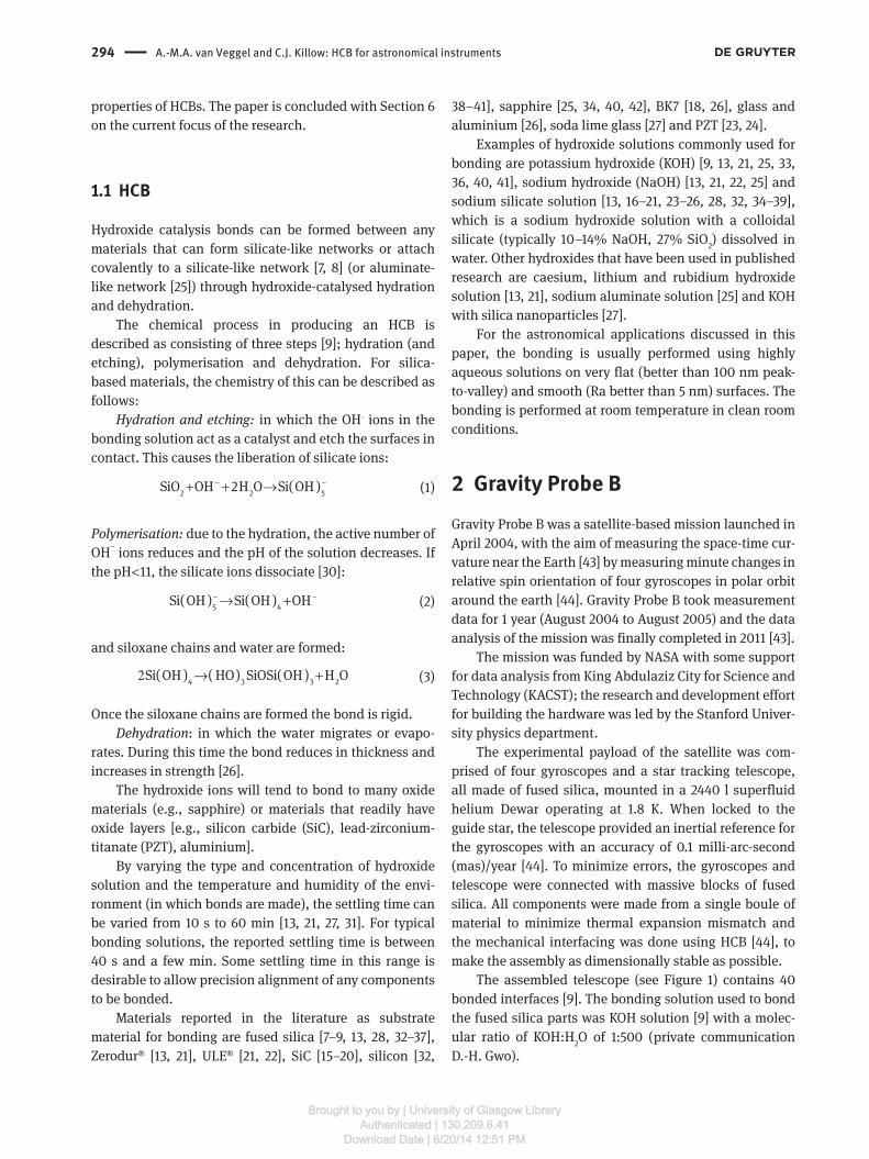
The experimental payload of the satellite was com-prised of four gyroscopes and a star tracking telescope, all made of fused silica, mounted in a 2440 l superfluid helium Dewar operating at 1.8 K. When locked to the guide star, the telescope provided an inertial reference for the gyroscopes with an accuracy of 0.1 milli-arc-second (mas)/year [44]. To minimize errors, the gyroscopes and telescope were connected with massive blocks of fused silica. All components were made from a single boule of material to minimize thermal expansion mismatch and the mechanical interfacing was done using HCB [44], to make the assembly as dimensionally stable as possible.
The assembled telescope (see Figure 1) contains 40 bonded interfaces [9]. The bonding solution used to bond the fused silica parts was KOH solution [9] with a molec-ular ratio of KOH:H2O of 1:500 (private communication D.-H. Gwo).
Brought to you by | University of Glasgow LibraryAuthenticated | 130.209.6.41
Download Date | 6/20/14 12:51 PM
A.-M.A. van Veggel and C.J. Killow: HCB for astronomical instruments 295
The noise performance of the telescope sensor assembly was measured to be well below the required < 10 mas/√Hz in a 0.15 Hz pointing control bandwidth [44].
Space qualification tests for the HCB technique for Gravity Probe B involved experiments on ∅25 mm × 6 mm fused silica discs with bonding surfaces polished to 50–100 nm peak-to-valley flatness using between 0.3 and 1.0 μl of KOH bonding solution with a molecular ratio KOH:H2O 1:500 [7]. Shear strength tests, thermal cycling tests and outgassing tests performed showed average shear strengths of 30 MPa, that samples survived multiple thermal shocks by dipping in liquid helium and that out-gassing was negligible.
3 GW detectorsGWs are a prediction of the theory of general relativity and they propagate through the universe by distorting the medium of space-time [45]. There is a concentrated worldwide effort to directly observe GWs, as this will bring a step-change in our understanding of the universe. The analogue that is often used is that if observing electro-magnetic radiation is akin to seeing the universe, then GW observation will be like hearing it: the sensing methodolo-gies are fundamentally different, and complementary. GW observatories will explore the electromagnetically dark universe, where we can currently only theorise and specu-late on the underlying physics.
The astrophysical sources of GWs are many and varied, and include events such as the inspiral and
Figure 1 Side view of the pre-flight prototype GP-B telescope made from fused silica. The actual flight version has clear sides. The overall cylindrical section is ∼43 cm long. Free of mechanical fasten-ers, the optics construction has over 40 bonding interfaces, which survive 2.5 K thermal cycling. Courtesy: Stanford University (http://einstein.stanford.edu/content/tech_stories/ts_11-telescope.html).
eventual merger of two black holes or neutron stars and the collapse of a star to form a neutron star or black hole [46, 47]. Long baseline laser interferometers targeted at the detection of GWs form the basis of a set of ground-based observatories operating in the frequency range from ∼10 Hz to 1 kHz, and are planned for use in a space-based observatory to operate between 0.1 and 100 mHz. In both cases, the relative positions of ‘test masses’ are monitored and GW information inferred from changes in their separation. It is expected that strain sensitivity of the order 10-22 needs to be measured to detect GWs, and this results in technological challenges requiring novel measurement techniques.
3.1 Space-based GW detectors
In November 2013, the European Space Agency (ESA) selected ‘The Gravitational Universe’ [48] as the science theme for its ‘L3’ mission, to be launched in 2034. This theme will study GWs in the low-frequency spectrum between 0.1 and 100 mHz. The ‘strawman’ mission to deliver the Gravitational Universe science theme is eLISA [47], a triangular arrangement of three drag-free spacecraft with million-kilometre arm lengths. Changes to the proper distance between test masses caused by GWs passing through the 109 m arms will be monitored to 10-12 m. There are many technological and scientific challenges to be overcome to achieve these goals; one in particular being the need to provide a stable and precise optical sensing scheme. The approach has been to benefit from HCB to create composite precision-aligned optical assemblies. The majority of the optical sensing required for eLISA is being verified in a smaller technology-demonstration mission, called LISA Pathfinder [49].
3.1.1 LISA Pathfinder
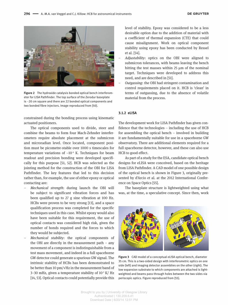
The LISA Pathfinder mission is due to launch in 2015, to demonstrate critical technologies for eLISA that can only be tested in microgravity [49]. It comprises two test masses, gold-platinum alloy cubes of 4.6 cm on a side, surrounded by a drag-free spacecraft. The optical bench interferome-ter (OBI) [50] is housed between the test masses and reads out their critical positions and attitudes with a precision of 10 pm and 20 nrad. The OBI is a quasi-monolithic, hydroxide catalysis bonded interferometer and is shown in Figure 2. The OBI bonds were made between fused silica and Zerodur surfaces using 1:6 volumetric ratio of sodium silicate solution to water. The component locations were
Brought to you by | University of Glasgow LibraryAuthenticated | 130.209.6.41
Download Date | 6/20/14 12:51 PM
296 A.-M.A. van Veggel and C.J. Killow: HCB for astronomical instruments
constrained during the bonding process using kinematic actuated positioners.
The optical components used to divide, steer and combine the beams to form four Mach-Zehnder interfer-ometers require absolute placement at the submicron and microradian level. Once located, component posi-tion must be picometre-stable over 1000 s timescales for temperature variations of ∼10-4 K. Techniques for beam readout and precision bonding were developed specifi-cally for this purpose [51, 52]. HCB was selected as the jointing method for the construction of the OBI for LISA Pathfinder. The key features that led to this decision rather than, for example, the use of either epoxy or optical contacting are:
– Mechanical strength: during launch the OBI will be subject to significant vibration forces and has been qualified up to 27 g sine vibration at 100 Hz. HCBs were proven to be very strong [13], and a space qualification process was completed for the specific techniques used in this case. Whilst epoxy would also have been suitable for this requirement, the use of optical contacts was considered high risk, given the number of bonds required and the forces to which they would be subjected.
– Mechanical stability: the optical components of the OBI are directly in the measurement path – any movement of a component is indistinguishable from a test mass movement, and indeed in a full spaceborne GW detector could generate a spurious GW signal. The intrinsic stability of HCBs has been demonstrated to be better than 10 pm/√Hz in the measurement band of 3–30 mHz, given a temperature stability of 10-3 K/ Hz [14, 53]. Optical contacts could potentially provide this
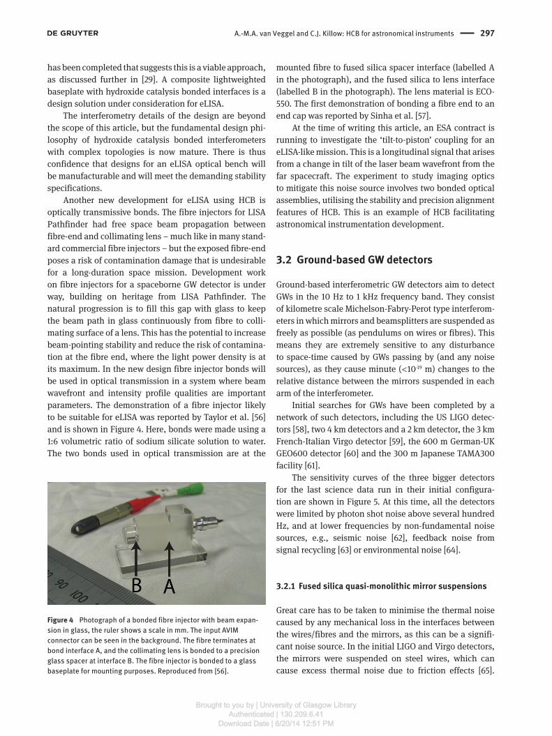
Figure 3 CAD model of a conceptual eLISA optical bench, diameter 35 cm. This is a two-sided design with interferometric optics on one side (left) and imaging detector assemblies on the other (right). The low expansion substrate to which components are attached is light-weighted and beams pass through holes between the two sides via periscopic optics. Figure reproduced from [55].
Figure 2 The hydroxide catalysis bonded optical bench interferom-eter for LISA Pathfinder. The top surface of the Zerodur baseplate is ∼20 cm square and there are 22 bonded optical components and two bonded fibre injectors. Image reproduced from [50].
level of stability. Epoxy was considered to be a less desirable option due to the addition of material with a coefficient of thermal expansion (CTE) that could cause misalignment. Work on optical component stability using epoxy has been conducted by Ressel et al. [54].
– Adjustability: optics on the OBI were aligned to submicron tolerances, with beams leaving the bench hitting the test masses within 25 μm of the nominal target. Techniques were developed to address this need, and are described in [51].
– Outgassing: the OBI had stringent contamination and control requirements placed on it. HCB is ‘clean’ in terms of outgassing, due to the absence of volatile material from the process.
3.1.2 eLISA
The development work for LISA Pathfinder has given con-fidence that the technologies – including the use of HCB for assembling the optical bench – involved in building it are fundamentally suitable for use in a spaceborne GW observatory. There are additional elements required for a full spaceborne detector, however, and these can also use HCB to good effect.
As part of a study for the ESA, candidate optical bench designs for eLISA were conceived, based on the heritage from LISA Pathfinder. A CAD model of one possible design of the optical bench is shown in Figure 3, originally pre-sented by d’Arcio et al. at the 2012 International Confer-ence on Space Optics [55].
The baseplate structure is lightweighted using what was, at the time, a speculative concept. Since then, work
Brought to you by | University of Glasgow LibraryAuthenticated | 130.209.6.41
Download Date | 6/20/14 12:51 PM
A.-M.A. van Veggel and C.J. Killow: HCB for astronomical instruments 297
has been completed that suggests this is a viable approach, as discussed further in [29]. A composite lightweighted baseplate with hydroxide catalysis bonded interfaces is a design solution under consideration for eLISA.
The interferometry details of the design are beyond the scope of this article, but the fundamental design phi-losophy of hydroxide catalysis bonded interferometers with complex topologies is now mature. There is thus confidence that designs for an eLISA optical bench will be manufacturable and will meet the demanding stability specifications.
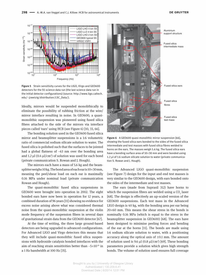
Another new development for eLISA using HCB is optically transmissive bonds. The fibre injectors for LISA Pathfinder had free space beam propagation between fibre-end and collimating lens – much like in many stand-ard commercial fibre injectors – but the exposed fibre-end poses a risk of contamination damage that is undesirable for a long-duration space mission. Development work on fibre injectors for a spaceborne GW detector is under way, building on heritage from LISA Pathfinder. The natural progression is to fill this gap with glass to keep the beam path in glass continuously from fibre to colli-mating surface of a lens. This has the potential to increase beam-pointing stability and reduce the risk of contamina-tion at the fibre end, where the light power density is at its maximum. In the new design fibre injector bonds will be used in optical transmission in a system where beam wavefront and intensity profile qualities are important parameters. The demonstration of a fibre injector likely to be suitable for eLISA was reported by Taylor et al. [56] and is shown in Figure 4. Here, bonds were made using a 1:6 volumetric ratio of sodium silicate solution to water. The two bonds used in optical transmission are at the
Figure 4 Photograph of a bonded fibre injector with beam expan-sion in glass, the ruler shows a scale in mm. The input AVIM connector can be seen in the background. The fibre terminates at bond interface A, and the collimating lens is bonded to a precision glass spacer at interface B. The fibre injector is bonded to a glass baseplate for mounting purposes. Reproduced from [56].
mounted fibre to fused silica spacer interface (labelled A in the photograph), and the fused silica to lens interface (labelled B in the photograph). The lens material is ECO-550. The first demonstration of bonding a fibre end to an end cap was reported by Sinha et al. [57].
At the time of writing this article, an ESA contract is running to investigate the ‘tilt-to-piston’ coupling for an eLISA-like mission. This is a longitudinal signal that arises from a change in tilt of the laser beam wavefront from the far spacecraft. The experiment to study imaging optics to mitigate this noise source involves two bonded optical assemblies, utilising the stability and precision alignment features of HCB. This is an example of HCB facilitating astronomical instrumentation development.
3.2 Ground-based GW detectors
Ground-based interferometric GW detectors aim to detect GWs in the 10 Hz to 1 kHz frequency band. They consist of kilometre scale Michelson-Fabry-Perot type interferom-eters in which mirrors and beamsplitters are suspended as freely as possible (as pendulums on wires or fibres). This means they are extremely sensitive to any disturbance to space-time caused by GWs passing by (and any noise sources), as they cause minute ( < 10-19 m) changes to the relative distance between the mirrors suspended in each arm of the interferometer.
Initial searches for GWs have been completed by a network of such detectors, including the US LIGO detec-tors [58], two 4 km detectors and a 2 km detector, the 3 km French-Italian Virgo detector [59], the 600 m German-UK GEO600 detector [60] and the 300 m Japanese TAMA300 facility [61].
The sensitivity curves of the three bigger detectors for the last science data run in their initial configura-tion are shown in Figure 5. At this time, all the detectors were limited by photon shot noise above several hundred Hz, and at lower frequencies by non-fundamental noise sources, e.g., seismic noise [62], feedback noise from signal recycling [63] or environmental noise [64].
3.2.1 Fused silica quasi-monolithic mirror suspensions
Great care has to be taken to minimise the thermal noise caused by any mechanical loss in the interfaces between the wires/fibres and the mirrors, as this can be a signifi-cant noise source. In the initial LIGO and Virgo detectors, the mirrors were suspended on steel wires, which can cause excess thermal noise due to friction effects [65].
Brought to you by | University of Glasgow LibraryAuthenticated | 130.209.6.41
Download Date | 6/20/14 12:51 PM
298 A.-M.A. van Veggel and C.J. Killow: HCB for astronomical instruments
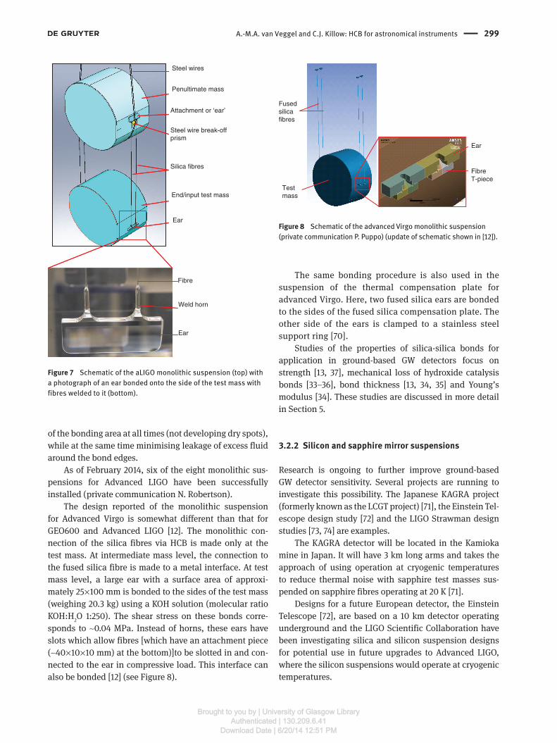
Ideally, mirrors would be suspended monolithically to eliminate the possibility of rubbing friction at the wire/mirror interface resulting in noise. In GEO600, a quasi-monolithic suspension was pioneered using fused silica fibres attached to the side of the mirrors via interface pieces called ‘ears’ using HCB (see Figure 6) [10, 33, 66].
The bonding solution used in the GEO600 fused silica mirror and beamsplitter suspensions is a 1:6 volumetric ratio of commercial sodium silicate solution to water. The fused silica is polished such that the surfaces to be jointed had a global flatness of ∼63 nm over the bonding area and 1.2 μl (0.4 μl/cm2) of solution was used for each bond (private communication S. Rowan and J. Hough).
The mirrors each have a mass of 5.6 kg and the beam-splitter weighs 10 kg. The bond area of each ear is 10 × 30 mm, meaning the peel/shear load on each ear is maximally 0.16 MPa under nominal load (private communication Rowan and Hough).
The quasi-monolithic fused silica suspensions in GEO600 were brought into operation in 2002. The eight bonded ears have now been in operation for 12 years, a combined duration of 96 years [11] showing no evidence for excess noise arising above what was considered thermal noise from the quasi-monolithic suspension at the violin mode frequency of the suspension fibres in several days of gravitational strain data from the GEO600 detector [67].
At the time of writing, the three large ground-based detectors are being upgraded to advanced configurations. For Advanced LIGO and Virgo detectors this means that they will include quasi-monolithic fused silica suspen-sions with hydroxide catalysis bonded interfaces with the aim of reaching strain sensitivities better than ∼5 × 10-24 in a 1 Hz bandwidth at 100 Hz [35].
Fused silica
fibres
Fused silica ears
Fused silicaintermediate mass
Fused silicatest mass
Aluminiumsupport structure
Figure 6 A GEO600 quasi-monolithic mirror suspension [66], showing the fused silica ears bonded to the sides of the fused silica intermediate and test masses with fused silica fibres welded to horns on the ears. The masses weigh 5.6 kg. The fused silica ears have a bonding surface area of 10 × 30 mm and were bonded using 1.2 μl of 1:6 sodium silicate solution to water (private communica-tion S. Rowan and J. Hough).
101 102 103 10410-23
10-22
10-21
10-20
10-19
10-18
10-17
Frequency (Hz)
Str
ain
sens
itivi
ty (
Hz-1
/2)
LIGO LHO 4 km S5LIGO LLO 4 km S5LIGO LHO 2 km S5GEO600 typical S5VIRGO VSR1
Figure 5 Strain sensitivity curves for the LIGO, Virgo and GEO600 detectors for the S5 science data run (the last science data run in the initial detector configurations) (source: http://www.ligo.caltech.edu/∼jzweizig/distribution/LSC_Data/).
The Advanced LIGO quasi-monolithic suspension (see Figure 7) design for the input and end test masses is very similar to the GEO600 design, with ears bonded onto the sides of the intermediate and test masses.
The ears (made from Suprasil 312) have horns to which the suspension fibres are welded using a CO2 laser [68]. The design is effectively an up-scaled version of the GEO600 suspensions. Each test mass in the Advanced LIGO design is 40 kg, with the bonding area per ear being 20 × 60 mm. This means the shear stress in the bonds is nominally 0.16 MPa (which is equal to the stress in the beamsplitter suspension in GEO600) [68]. The ears have been designed to minimise peeling forces and bending of the ear at the horns [11]. The bonds are made using 1:6 sodium silicate solution to water, with a positioning accuracy along the optical axis of ± 0.1 mm. The amount of solution used is 9.6 μl (0.8 μl/cm2) [69]. These bonding parameters provide a solution which gives high strength bonds. The volume of solution used ensures full coverage
Brought to you by | University of Glasgow LibraryAuthenticated | 130.209.6.41
Download Date | 6/20/14 12:51 PM
A.-M.A. van Veggel and C.J. Killow: HCB for astronomical instruments 299
of the bonding area at all times (not developing dry spots), while at the same time minimising leakage of excess fluid around the bond edges.
As of February 2014, six of the eight monolithic sus-pensions for Advanced LIGO have been successfully installed (private communication N. Robertson).
The design reported of the monolithic suspension for Advanced Virgo is somewhat different than that for GEO600 and Advanced LIGO [12]. The monolithic con-nection of the silica fibres via HCB is made only at the test mass. At intermediate mass level, the connection to the fused silica fibre is made to a metal interface. At test mass level, a large ear with a surface area of approxi-mately 25 × 100 mm is bonded to the sides of the test mass (weighing 20.3 kg) using a KOH solution (molecular ratio KOH:H2O 1:250). The shear stress on these bonds corre-sponds to ∼0.04 MPa. Instead of horns, these ears have slots which allow fibres [which have an attachment piece (∼40 × 10 × 10 mm) at the bottom)]to be slotted in and con-nected to the ear in compressive load. This interface can also be bonded [12] (see Figure 8).
Fusedsilicafibres
Testmass
FibreT-piece
Ear
Figure 8 Schematic of the advanced Virgo monolithic suspension (private communication P. Puppo) (update of schematic shown in [12]).
Steel wires
Penultimate mass
Silica fibres
End/input test mass
Ear
Attachment or ‘ear’
Steel wire break-offprism
Ear
Weld horn
Fibre
Figure 7 Schematic of the aLIGO monolithic suspension (top) with a photograph of an ear bonded onto the side of the test mass with fibres welded to it (bottom).
The same bonding procedure is also used in the suspension of the thermal compensation plate for advanced Virgo. Here, two fused silica ears are bonded to the sides of the fused silica compensation plate. The other side of the ears is clamped to a stainless steel support ring [70].
Studies of the properties of silica-silica bonds for application in ground-based GW detectors focus on strength [13, 37], mechanical loss of hydroxide catalysis bonds [33–36], bond thickness [13, 34, 35] and Young’s modulus [34]. These studies are discussed in more detail in Section 5.
3.2.2 Silicon and sapphire mirror suspensions
Research is ongoing to further improve ground-based GW detector sensitivity. Several projects are running to investigate this possibility. The Japanese KAGRA project (formerly known as the LCGT project) [71], the Einstein Tel-escope design study [72] and the LIGO Strawman design studies [73, 74] are examples.
The KAGRA detector will be located in the Kamioka mine in Japan. It will have 3 km long arms and takes the approach of using operation at cryogenic temperatures to reduce thermal noise with sapphire test masses sus-pended on sapphire fibres operating at 20 K [71].
Designs for a future European detector, the Einstein Telescope [72], are based on a 10 km detector operating underground and the LIGO Scientific Collaboration have been investigating silica and silicon suspension designs for potential use in future upgrades to Advanced LIGO, where the silicon suspensions would operate at cryogenic temperatures.
Brought to you by | University of Glasgow LibraryAuthenticated | 130.209.6.41
Download Date | 6/20/14 12:51 PM
300 A.-M.A. van Veggel and C.J. Killow: HCB for astronomical instruments
First results of studies of the properties of hydroxide catalysis sapphire-sapphire bonds have been reported by Douglas et al. [25], Dari et al. [40] and Suzuki et al. [42]. Studies of HCBs of silicon to silicon have been reported by van Veggel et al. [32], Dari et al. [40], Lorenzini et al. [41], and Beveridge et al. [38, 39]. Most of the work reported in the literature focussed on the shear and tensile strength of bonds between silicon and sapphire, along with initial studies of the thermal conductance of bonds and scanning electron microscopy imaging of bonded interfaces. An overview of the results is given in Section 5.1 of this paper.
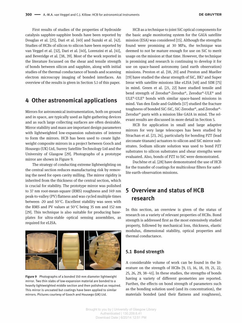
4 Other astronomical applicationsMirrors for astronomical instrumentation, both on ground and in space, are typically used as light-gathering devices and as such large collecting surfaces are often desirable. Mirror stability and mass are important design parameters with lightweighted low-expansion substrates of interest to form the mirrors. HCB has been used to create light-weight composite mirrors in a project between Gooch and Housego (UK) Ltd, Surrey Satellite Technology Ltd and the University of Glasgow [29]. Photographs of a prototype mirror are shown in Figure 9.
The strategy of conducting extreme lightweighting on the central section reduces manufacturing risk by remov-ing the need for open cavity milling. The mirror rigidity is inherited from the thickness of the central section, which is crucial for stability. The prototype mirror was polished to 37 nm root-mean-square (RMS) roughness and 149 nm peak-to-valley (PV) flatness and was cycled multiple times between -20 and 50°C. Excellent stability was seen with the RMS and PV values at 50°C being 35 nm and 152 nm [29]. This technique is also suitable for producing base-plates for ultra-stable optical sensing assemblies, as required for eLISA.
Figure 9 Photographs of a bonded 150 mm diameter lightweight mirror. Two thin slabs of low-expansion material are bonded to a heavily lightweighted middle section and then polished as required. This mirror is uncoated but coatings have been applied to similar mirrors. Pictures courtesy of Gooch and Housego (UK) Ltd.
HCB as a technique to joint SiC optical components for the basic angle monitoring system for the GAIA satellite mission (ESA) was considered [15]. Although the strengths found were promising at 30 MPa, the technique was deemed to not be mature enough for use on SiC to merit usage on the mission at that time. However, the technique is promising and research is continuing to develop it for use on space-based astronomy (and earth observation) missions. Preston et al. [18, 20] and Preston and Mueller [19] have studied the shear strength of SiC, BK7 and Super Invar with satellite missions like eLISA [48] and SIM [75] in mind. Green et al. [21, 22] have studied tensile and bend strength of Zerodur®-Zerodur®, Zerodur®-ULE® and ULE®-ULE® bonds with similar space-based missions in mind. Van den Ende and Gubbels [17] studied the fracture toughness of bonded SiC-SiC, SiC-Zerodur®, and Zerodur®-Zerodur® parts with a mission like GAIA in mind. The rel-evant results are discussed in more detail in Section 5.
HCB for application in small and large adaptive mirrors for very large telescopes has been studied by Strachan et al. [23, 24], particularly for bonding PZT (lead zirconate titanate) actuators to silicon and SiC mirror sub-strates. Sodium silicate solution was used to bond PZT substrates to silicon substrates and shear strengths were evaluated. Also, bonds of PZT to SiC were demonstrated.
Duchêne et al. [28] have demonstrated the use of HCB for the transfer of coatings for multicolour filters for satel-lite earth-observation missions.
5 Overview and status of HCB research
In this section, an overview is given of the status of research on a variety of relevant properties of HCBs. Bond strength is addressed first as the most extensively studied property, followed by mechanical loss, thickness, elastic modulus, dimensional stability, optical properties and thermal conductance.
5.1 Bond strength
A considerable volume of work can be found in the lit-erature on the strength of HCBs [9, 13, 16, 18, 19, 21, 22, 25, 26, 29, 38–41]. In these studies, the strengths of bonds having a variety of different geometries are reported. Further, the effects on bond strength of parameters such as the bonding solution used (and its concentration), the materials bonded (and their flatness and roughness),
Brought to you by | University of Glasgow LibraryAuthenticated | 130.209.6.41
Download Date | 6/20/14 12:51 PM
A.-M.A. van Veggel and C.J. Killow: HCB for astronomical instruments 301
the cleaning technique used to prepare the surfaces to be jointed and the curing time and method have been investigated.
Table 1 shows a summary of some of the strength results reported in the literature, in an attempt to give the reader an overview of the status of this research. It should be noted that this table is not exhaustive due to the large number of individual results. However, the table shows some comparative results on like-for-like bonded substrates categorised by material: fused silica, sapphire, silicon, SiC, ULE, Zerodur and BK7. Only results from sub-strates bonded with either NaOH, KOH or sodium silicate are included. Cleaning method, flatness and roughness of bonding surfaces and curing time and method are not explicitly considered in this table, even though they have been shown to have influence on the strength reached. However, all tests shown in this table used samples with flatnesses better than 160 nm, were smooth, and the sur-faces of which were cleaned thoroughly. The tests listed involved curing for at least 1 week at room temperature, or had an elevated temperature bake, which accelerates the curing as described below, apart from those reported in [18, 19] which were cured for 18 h at room temperature.
On inspection of Table 1, one can see that there is a large variation in average strengths found, 1.19–70 MPa, and the factors influencing this are clearly of interest. Bond strength is highly sensitive to edge conditions. Therefore, particularly in shear strength tests, great care has to be taken to not introduce peeling stresses. In a study by Elliffe et al. [13], a significant peeling force was created, most probably leading to the low strengths of 1.19–2.70 MPa shown in Table 1. Some peeling force is also introduced in the measurement technique used by Preston et al. [18] and Preston and Mueller [19], which may explain the relatively low bond strengths found for SiC and BK7 bonds. It should be noted that in the application of HCB in, e.g., optical benches, telescopes or mirror suspen-sions, some level of peeling forces may be unavoidable and therefore the results showing these lower strengths are valuable.
Van den Ende and Gubbels [17] address the stress con-centration issue by measuring the fracture toughness of HCBs between SiC and Zerodur instead of strength, and deliberately introduce high stress concentrations into the edge of the bonds. They found the fracture toughness of HCBs to be higher than 1 MPa m-1/2. For SiC fracture, values of toughness reported are 2.3–3.5 MPa m-1/2 [76]. The frac-ture toughness reported for Zerodur is 0.8–1.1 MPa m-1/2 [77].
For bonding silicon, Beveridge et al. [38] showed that the bonds between silicon substrates are strongest and most reliable when applying an oxide layer with a
minimum thickness of 50 nm (when using a wet thermal oxide) to the substrates, indicating the native oxide layer on the silicon is not enough to create reliably strong bonds. One possible cause is hydrogen formation [32] due to the hydroxide reaching the bare silicon if the oxide layer is too thin (see Section 5.2 for more information). The strength also depends on the type of oxide layer applied [39]. Dari et al. [40] did not oxidise the surfaces, but cleaned the substrates using 5:1 volumetric ratio H2SO4 (96%):K2Cr2O7. The rate of success in creating good bonds was somewhat lower than for Beveridge et al. [38], supporting the relia-bility finding. Nevertheless, they created successful bonds using this technique with some shear strength. The shear strengths they reported are lower than the tensile strength found by Beveridge et al. However, because the strength test methods applied are different, no comparative con-clusions can be drawn.
One could expect a similar result for bonding SiC, which is why Van Veggel et al. [16] oxidized their SiC samples. Preston and Mueller [19] showed, however, that successful bonds can be created between SiC substrates without the use of an additional oxide layer. Van den Ende and Gubbels [17] showed that the fracture toughness of SiC-SiC bonds cleaned with 0.1 M NaOH solution (pH 13) in demineralized water, heated to 35°C for 4 h, is the same within error as SiC-SiC bonds with thermally oxidised sur-faces (78 nm thick), which suggests hydrogen formation is not a problem for SiC-SiC bonds.
Table 1 shows consistently lower shear strength results than tensile results. A systematic test of any ani-sotropy in the mechanical behaviour of HCBs would be of interest to determine if this observation is an artifact of the individual measurement techniques used, or if HCBs are, in fact, anisotropic.
Studies reported in [25, 37–39] find higher strengths using the 4-point bending technique for silica, silicon and sapphire than are found elsewhere using other geometries of strength testing techniques. This is possibly because the high stress intensity is confined to a 10 mm long edge at the bottom of the sample and the strength found is not sensitive to precise alignment of the sample. This tech-nique has been used to evaluate bond strengths down to 77 K for silicon and sapphire samples. This experimental technique also suggests that the strength and/or stiffness of the bulk material influences the total bond strength found, with the highest bond strengths found for sap-phire, followed by silicon and then silica (which is the weakest and has the lowest Young’s modulus of the three materials). Of note, is that higher strengths are found for measurements taken at 77 K than at room temperature, which requires investigation.
Brought to you by | University of Glasgow LibraryAuthenticated | 130.209.6.41
Download Date | 6/20/14 12:51 PM

302 A.-M.A. van Veggel and C.J. Killow: HCB for astronomical instruments
Table 1 Overview of some strength results in the literature.
Reference Details material bonded
Bond area Bonding solution Average strength (MPa)
No. of samples
Type of strength test
Temperature of strength test [K]
Source in reference
Fused silica [9] – ∅25 mm KOH:H2O 1:500 30 ( ± ?) ? Shear test Not stated p. 138 [13] – 10 × 5 mm NaOH:H2O 1:500 2.70 ( ± 0.23) 5 Peel/shear test R.T. table 6 [13] – 10 × 5 mm KOH:H2O 1:500 1.19 ( ± 0.14) 5 Peel/shear test R.T. table 6 [13] – 10 × 5 mm Sodium silicate 1:4 2.14 ± 0.54 5? Peel/shear test R.T. table 3 [13] – 10 × 5 mm Sodium silicate 1:6 1.45 ± 0.08 5? Peel/shear test R.T. table 3 [32] – ∅25.4 mm Sodium silicate 1:6 4.1 (1.8–7.5) 5 Shear test R.T. figure 5 [37] Corning 7980 5 × 10 mm Sodium silicate 1:6 14 ( ± 1) 10 Tensile (in 4-point bend) R.T. figure 3.14 [37] Suprasil 312 5 × 10 mm Sodium silicate 1:6 20 ( ± 1) 10 Tensile (in 4-point bend) R.T. figure 3.20Sapphire [42] //c-axis ∅10 mm KOH:H2O 1:? 6.5 1 Shear (in torque) R.T. table 3 [40] c-axis ∅5 mm 1:250 KOH:H2O 2 (1–2) 12 Shear test R.T. figure 8 [25] M-axis 5 × 10 mm Sodium silicate 1:6
(pH 12) 70 (38–89) 10 Tensile (in 4-point bend) 77 K p. 7
[25] M-axis 5 × 10 mm Sodium silicate 1:6 (pH 12)
65 (38–91) 10 Tensile (in 4-point bend) R.T p. 7
[25] M-axis 5 × 10 mm NaOH:H2O 1:100 (pH 12)
12 (7–16) 10 Tensile (in 4-point bend) R.T p. 7
[25] M-axis 5 × 10 mm KOH:H2O 1:190 (pH 12)
16 (7–58) 10 Tensile (in 4-point bend) R.T p. 7
Silicon [32] (111) with dry
thermal oxide ∅25.4 mm Sodium silicate 1:6 4.8 (2.6–6.9) 6 Shear test R.T. figure 5
[32] (100) with dry thermal oxide
∅25.4 mm Sodium silicate 1:6 3.6 (2.8–4.7) 3 Shear test R.T. figure 5
[40] (100) ∅5 mm 1:250 KOH:H2O 8 (6–10) 15 Shear test R.T. figure 8 [40] (111) ∅5 mm 1:250 KOH:H2O 9 (6–12) 15 Shear test R.T. figure 8 [38] Random wet
thermal oxide 5 × 10 mm Sodium silicate 1:6 35 (9–54) 37 Tensile (4-point bend) R.T. figure 6
[38] Random with wet thermal
5 × 10 mm Sodium silicate 1:6 41 (6–57) 33 Tensile (4-point bend) 77 K figure 6
[39] (111)+IBS SiO2 5 × 10 mm Sodium silicate 1:6 34 ( ± 2) 13 Tensile (in 4-point bend) 77 K p. 12 [39] (111)+IBS SiO2 5 × 10 mm Sodium silicate 1:6 24 ( ± 3) 12 Tensile (in 4-point bend) R.T. p. 12SiC [16] C/SiC and
Hexoloy SiC 3.2 × 10.5
mm Sodium silicate 1:6 5.4–31.5 11 Tensile (in 4-point bend) R.T. table 5
[19] Saint-Gobain Hexoloy SiC
9 × 6 mm Sodium silicate 1:4 6 1 Shear strength (with some peel force)
R.T. table 1
[19] Poco Super SiC 10 × 10 mm Sodium silicate 1:4 2.45 1 Shear strength (with some peel force)
R.T. table 1
[19] Coorstek Ultra SiC
10 × 10 mm Sodium silicate 1:4 4.5 (2.2–7.1) 5 Shear strength (with some peel force)
R.T. table 1
ULE [22] ULE ∅25.4 mm 1:1000 NaOH:H2O 10.1 35 Tensile R.T. figure 7 [21] ULE 12 × 25 mm 1:500 NaOH:H2O 12.2 (4–16) 6 Tensile R.T. figure 15 [21] ULE 12 × 25 mm 1:500 KOH:H2O 6.7 (4–9) 6 Tensile R.T. figure 15Zerodur [21] Zerodur 12 × 25 mm 1:500 NaOH:H2O 4.4 (3.0–6.5) 11 Tensile R.T. figure 9 [21] Zerodur 12 × 25 mm 1:500 KOH:H2O 1.7 (1.2–2.8) 11 Tensile R.T. figure 9 [21] Zerodur 12 × 25 mm Sodium silicate 1:4 10.3 (9–12) 4 Tensile R.T. figure 12BK7 [18] BK7 ∅12.7 mm Sodium silicate 1:4 3.2 (1.7–7.6) 21 Shear test (with small
peel effect) R.T. p.370
[26] BK7 12.5 × 8 mm Sodium silicate 1:4 31.8 (?) 7 Shear R.T. p. 30
Brought to you by | University of Glasgow LibraryAuthenticated | 130.209.6.41
Download Date | 6/20/14 12:51 PM

A.-M.A. van Veggel and C.J. Killow: HCB for astronomical instruments 303
Two independent research groups have found, for dif-ferent substrate materials, that bonds made with sodium silicate solution are stronger than bonds made with a pure sodium or KOH solution, see Douglas et al. [25] (studying sapphire bonds) and Green et al. [21] (studying Zerodur bonds). Results reported by Elliffe et al. [13] do not show this difference, but this could well be caused by the strong peeling force in their experiments and therefore sensitiv-ity to edge conditions at the bond interface.
In almost all of the studies in the literature, the sub-strate material is reported to fail before the bond, suggest-ing that the bond material (being so thin) is stronger than the substrate material.
Maximum bond strength is reached in approximately 4 weeks when curing at room temperature. A 4-week curing time to reach final bond strength has been in common use for many years, and was comprehensively demonstrated by Kim and Schmitz [26].
Curing at elevated temperatures or under reduced pressure for some period during the curing period has been shown to have either no effect, or a positive effect on strength, as reported by Kim and Schmitz [26] and Green et al. [21]. Several authors report on the effects of thermal shock on bonded samples, by submerging them in liquid nitrogen or helium to investigate if they will survive extreme thermal cycling. Elliffe et al. [13] reported that they saw no visual degradation of bonds between different materials that had been cycled between 77 and 350 K. Gwo [9] tested the strength of silica-silica bonds after thermal cycling between 2.5 and 300 K and found no degradation.
5.2 Bond thickness
Gwo states in his patents [7, 8] that by adapting the chem-istry of the bonding solution used along with the figure of the surfaces to be bonded, bond thicknesses of anywhere between 10 nm and 10 μm can be achieved. For Gravity Probe B, a bond thickness of ∼200 nm was measured, which corresponded to the surface figure mismatch of the two bonding surfaces [9]. Other bond thickness measure-ments of HCBs can primarily be found in research directed at ground-based GW detectors [13, 21, 34, 35, 38].
For this application, the bond thickness is ideally as low as possible, because it is postulated that the lower the bond thickness the smaller the amount of strain energy that can be stored in the bond and therefore, the smaller the thermal noise associated with the bond. To enable appropriate alignment accuracy for high precision optical components in systems such as the LISA pathfinder
optical bench, very thin ( < 200 nm) bonds are important to minimize the tilt of the laser beam [51].
Elliffe et al. [13], Sneddon et al. [34] and Cunningham et al. [35] all report on bond thickness for bonds between fused silica substrates with nominal flatness of λ/10 (λ = 633 nm) made using sodium silicate solution (1:4 and 1:6 volumetric ratio). Numbers reported are 81 ± 4, 100 ± 7 and 81 ± 3 (for 1:4 and 1:6 sodium silicate solution), and 61 ± 4 nm, respectively, for the different authors. Elliffe et al. also reported a bond thickness of 26 ± 6 nm for bonds made using KOH (1:500 molecular ratio). The latter result appears to suggest that it is not just surface figure mis-match that dictates bond thickness. Measurement tech-niques used were atomic force microscopy and scanning electron microscopy.
Van Veggel et al. [32] and Beveridge et al. [38] report on bond thickness measurements of silicon-silicon bonds using 1:6 sodium silicate solution and the samples were nominally flat to λ/10 (λ = 633 nm). These samples also had a thermal oxide layer on either side of the bond. Both do not see a reduction (within error) in the oxide layer thickness, due to the etching of the oxide during the bonding process. Beveridge et al. [38] found bond thicknesses of between 30 and 45 nm for five silicon samples with different oxide layer thicknesses, using scanning electron microscopy. Van Veggel et al. [32] had earlier reported highly wedged bonds with the most extreme slice running from 50 nm to 6 μm. The postulated reason for the wedge was hydrogen forma-tion due to the bonding solution making direct contact with the silicon, as some of the oxide was removed before bonding for oxide thickness measurements. This was con-firmed when Beveridge et al. [38] ensured the bonding solution did not make contact with exposed silicon for their bond thickness measurement and found indeed no wedge.
5.3 Mechanical loss
As described above, the mechanical loss of mirror sus-pension elements in ground-based GW detectors is of importance, including the HCBs used in quasi-monolithic suspensions. Rowan et al. [33] studied the mechanical loss of a fused silica test mass (0.5 kg) suspended on a bonded (using 1:500 KOH:H2O) attachment piece with the prospect of building quasi-monolithic fused silica suspensions for GEO600 in 1998. The excess mechanical loss from the bonded area of ∼0.8 cm2 was found to be (3 ± 1) × 10-8. When scaled to the GEO600 test masses, the excess loss arising from the bonds was expected to be approximately 2 × 10⁻¹⁰, which was negligible compared to the intrinsic loss of the fused silica test masses themselves.
Brought to you by | University of Glasgow LibraryAuthenticated | 130.209.6.41
Download Date | 6/20/14 12:51 PM
304 A.-M.A. van Veggel and C.J. Killow: HCB for astronomical instruments
At that stage, no measurements existed of the Young’s modulus or bond thickness of hydroxide catalysis bonds, so the intrinsic loss of the bond could not be determined. This was first done by Sneddon et al. [34] in 2003 for three hydroxide catalysis bonds made with sodium silicate solution.
Using mechanical loss measurements from three dif-ferent fused silica and sapphire substrates with bonded interfaces, they determined intrinsic loss values of the bonds to be between 0.18 and 0.54. All measurements were suspension limited, which means the intrinsic bond loss found can be treated as an upper limit. Smith et al. [36] published loss measurements of bonds in long thin Suprasil 1 half cylinders (∅5 mm) bonded with KOH and sodium silicate solution. They report much higher values of the bond loss (ranging from 1.3 to 190). It was postulated that, because these bonds had unbonded regions, friction losses also occurred, which was not taken into account in the analysis. However, using these higher intrinsic bond losses, the excess loss from bonds in a potential quasi-monolithic fused silica suspension for LIGO was still expected to be of the order 106 smaller than the intrinsic loss of the test masses.
Cunningham et al. [35] reported an intrinsic bond loss of 0.11 ± 0.02 measured on two fused silica cylinders of dif-ferent length, bonded using 1:6 sodium silicate solution. The asymmetric design allowed the suspension limit to be pushed down, thus setting a new upper limit for the intrinsic bond loss using the same Young’s modulus and bond thickness as used by Sneddon et al. [34]. Using this information and newly developed finite element analysis (FEA) techniques, the thermal noise arising from 61 nm thick bond in the advanced LIGO suspension mirror sus-pension at 100 Hz was determined to be 5.4 × 10⁻²² ± 10%.
5.4 Elastic modulus
There is just one measurement of the elastic modulus of a silica-silica sodium silicate bond (1:4 volumet-ric ratio) available in literature. Sneddon et al. [34] reports on making a bond with bond thickness 1 μm, to allow for the use of a nano-indentation technique to determine a Young’s modulus of 7.9 GPa (∼1/10 of the Young’s modulus of fused silica). The elastic modulus is an important parameter for the determination of the amount of elastic energy entering an HCB in a GW detec-tor test mass suspension, to determine the thermal noise introduced by HCBs. For more accurate predictions of thermal noise introduced by bonds in these systems,
more measurements of bonds made using the actual procedure used in building the test mass suspensions is needed.
5.5 Dimensional stability
Dimensionally stable materials are of interest for many astronomical instruments – low CTE materials in par-ticular have been studied, see, e.g., [78, 79]. Hydroxide catalysis bonded optical assemblies have been shown to possess high positional stability. The work described in Robertson et al. [53] involved bonding multiple optical components to a low CTE substrate and monitoring their positional stability, which was measurement limited at 8 pm/√Hz at 10 mHz. This provided an upper limit to the dimensional stability of a bonded optical assembly, with thermally driven effects the limiting factor. The optical assembly discussed by Robertson et al. was also meas-ured using different readout equipment as described by Heinzel et al. [14], showing an improved measurement of the stability of ∼2 pm/√Hz. Also described in this paper, is the testing of another bonded optical bench, the LISA Technology Package Engineering Model, which showed similar stability. A further demonstration of ultra-stable optical benches made using hydroxide catalysis bonded optics to a low CTE substrate can be found in Dehne et al. [80].
It is evident from the above work that HCB provides a means of forming composite assemblies from low CTE materials, whilst maintaining the overall stability. This property has been utilised in the work of Fox [81], where mirrors were bonded to a spacer to assist in determining the temperature dependence of surface-mounted optical cavities, with no apparent instability contribution from the bonded parts. Preston et al. [20] report on related work that is ongoing to set up an experiment to test the stability of cavities using bonded mirrors.
5.6 Optical properties
It is qualitatively apparent from viewing bonded interfaces in transparent materials of the same refractive index that HCBs are transparent to visible light. Transparent inter-faces are of use in applications that require light transmis-sion through an interface, particularly if the absorption is low, which enables higher light power density to be trans-mitted without damaging the interface.
Sinha et al. [57] studied bonded interfaces between optical fibre ends and fused silica, a situation where high
Brought to you by | University of Glasgow LibraryAuthenticated | 130.209.6.41
Download Date | 6/20/14 12:51 PM
A.-M.A. van Veggel and C.J. Killow: HCB for astronomical instruments 305
light power density can be needed. The investigations were conducted using 1064 nm light. No damage was seen when bonds were irradiated with 40 W of continuous wave light focussed to 20 μm. Pulsed light of duration 25 ns and 1/e2 spot diameter of 250 μm was found to damage the most resilient bonded interfaces at levels > 70 J/cm2, and the authors comment that this is approaching the level expected for a well-prepared fused silica surface. Measure-ments of the reflection of light from a selection of bonded interfaces that had been bonded using different parame-ters were seen to be very low – as much as 63 dB below the incoming light levels, which was the measurement limit. No scattering was observed from the bond layers.
The work of Sinha et al. shows that HCBs can exhibit good optical properties, and as high-powered lasers become more commonplace, it is likely that this will become increasingly relevant to optical systems and astro-nomical instrumentation.
The development work on the fibre injectors for eLISA as reported in Taylor et al. [56] and discussed in section 3.1.3 has shown that this bonded fibre injector assembly exhibits a transmitted beam with wavefront flatness better than 63 nm over the central portion of the beam. Investiga-tions into the optical properties of the bonds for this type of application and other applications, like high power laser crystals assembled using HCB, are ongoing.
5.7 Thermal conductance
As mentioned in Section 3.2.2, the thermal conductance of HCBs is an important property for understanding the development of cryogenically operating quasi-monolithic test mass suspensions for future generation ground-based GW detectors, in order to extract the heat deposited into the test masses by the illuminating laser beam. Initial studies of this property have been made by Lorenzini et al. [41], who have measured the thermal conductance of silicon samples ∅25 mm × 80 mm with an HC bond 30 mm from one end. They reported that the thermal conduct-ance appeared to not be significantly changed by the HCB bond as compared to the bulk material in the temperature range 77–300 K. This is an active area of current research.
6 Current focus of the researchHCB of glass like materials (e.g., fused silica and Zerodur®) has been shown to be a highly suitable jointing tech-nique for ultra-high vacuum, ultra-low temperature, high
mechanical load, extremely dimensionally stable systems like the star-tracking telescope in Gravity Probe B, and LISA Pathfinder.
For space-based GW detectors and other applications (like high power laser applications) an important current focus is to develop and tailor HCB of, e.g., fused silica and sapphire for use in optical assemblies in which light is transmitted through the bond.
HCB of fused silica parts has now been successfully used and developed for several room temperature inter-ferometric ground-based GW detectors operating at room temperature. However, with an eye on future generation detectors operating at cryogenic temperatures down to 20 K, with mirror suspensions made of silicon and sap-phire, research is in full swing to investigate the feasibility of quasi-monolithic suspension designs using sapphire and silicon, possibly using HCB to aid assembly. Impor-tant questions to answer in this research are:
– What strength of these bonds can be achieved? The bonds need to be strong and reliable both at room temperature and cryogenic temperature.
– What thermal conductance can be achieved? As the thermal conductance needs to be highly efficient to allow extraction of heat in the mirrors resulting from residual laser light being absorbed
– What is the mechanical loss associated with these bonds at these low temperatures? As, discussed in Section 5.3, the mechanical loss associated with bonds can be a source of thermal noise and thus should be minimised.
Another important current research focus is the use of HCB in assemblies made of SiC for use in satellites like SIM and GAIA (and military applications). SiC is very strong, has low density and is very thermally stable due to a favour-able combination of thermal properties (being low CTE, high thermal conductivity). Missions considered in the past required highly stable lightweight optical assemblies in their payload. Further development of HCB for these mate-rials providing extremely stable, space-qualified joints that can operate at cryogenic temperatures is of high priority.
Acknowledgments: The authors would like to thank the UK Science and Technology Facilities Council (grant num-bers ST/I001085/1, ST/J000361/1 and ST/L000946/1), the University of Glasgow, the Scottish Funding Council, the Royal Society (grant number DH120021) and the Scottish Universities Physics Alliance for financial support. We also wish to thank our colleagues in the LIGO Scientific, Virgo, KAGRA and LISA collaborations for their interest in this work.
Brought to you by | University of Glasgow LibraryAuthenticated | 130.209.6.41
Download Date | 6/20/14 12:51 PM
306 A.-M.A. van Veggel and C.J. Killow: HCB for astronomical instruments
References[1] F. Twyman, Prism and Lens Making, 2nd ed. (Hilger & Watts,
London, 1952).[2] J. Haisma and G. A. C. M. Spierings, Mater. Sci. Eng. 37, 1–60
(2002).[3] V. Greco, F. Marchesini and G.J. Molesini, Opt. A: Pure Appl.
Opt. 3, 85–88 (2001).[4] O. M. J. Akselsen, Mater. Sci. 27, 569–579 (1992).[5] A. Plossl and G. Krauter, Mater. Sci. Eng. 25, 1–88 (1999).[6] J. R. Wimperis and S. F. Johnston, Appl. Opt. 23, 1145–1147 (1984).[7] D.-H. Gwo, US Patent no. US 6 284 085 B1 (2001).[8] D.-H. Gwo, US Patent no. US6548176 (2003).[9] D.-H. Gwo, SPIE Proc. 3435, 136–42 (1998).
[10] B. Willke, P. Aufmuth, C. Aulbert, S. Babak, R. Balasubrama-nian, et al., Classical Quant. Grav. 19, 1377 (2002).
[11] S. M. Aston, M. A. Barton, A. S. Bell, N. Beveridge, B. Bland, et al., Classical Quant. Grav. 29, 235004 (2012).
[12] M. Lorenzini on behalf of Virgo Collaboration, Classical Quant. Grav. 27, 084021 (2010).
[13] E. J. Elliffe, J. Bogenstahl, A. Deshpande, J. Hough, C. Killow, et al., Classical Quant. Grav. 22, S257–S267 (2005).
[14] G. Heinzel, C. Braxmaier, M. Caldwell, K. Danzmann, F. Draa-isma, et al., Classical Quant. Grav. 22, S149–S154 (2005).
[15] S. Rowan, J. Hough, E. Elliffe, UK Patent no. 040 7953.9 (2004).[16] A. A. van Veggel, D. van den Ende, J. Bogenstahl, S. Rowan, W.
Cunningham, et al., J. Eur. Ceram. Soc. 28, 303–310 (2008).[17] D. A. van den Ende and G. H. M. Gubbels, Mater. Chem. Phys.
143, 1236–1242 (2014).[18] A. Preston, B. Balaban and G. Mueller, Int. J. Appl. Ceram. Tec.
5, 365–372 (2008).[19] A. Preston and G. Mueller, Int. J. Appl. Ceram. Tec. 9, 764–771
(2012).[20] A. Preston, R. Cruz, J. I. Thorpe, G. Mueller and R. Delgadillo,
Proc. of SPIE 6273, 627321 (2006).[21] K. Green, J. Burke and B. Oreb, Opt. Eng. 50, 023401 (2011).[22] K. Green, J. Burke and B. Oreb, Mater. Chem. Phys. 130,
577–582 (2011).[23] M. Strachan, D. Montgomery, R. Myers, K. Cooke, J. Hampshire,
et al., Proc. SPIE 7736, 773664 (2010).[24] M. Strachan, R. Myers, K. Cooke, J. Hampshire, J. Hough, et al.,
Proc. SPIE 7736, 773661 (2010).[25] R. Douglas, A. A. van Veggel, L. Cunningham, K. Haughian, J.
Hough, et al., Classical Quant. Grav. 31, 045001 (2014).[26] H. S. Kim and T. L. Schmitz, Precis. Eng. 37, 23–32 (2013).[27] S. Sivasankar and S. Chu, Nano Lett. 7, 3031–3034 (2007).[28] M. Duchêne, A. A. van Veggel, F. Lemarquis, C. Grèzes-Besset,
S. Rowan, et al., Opt. Commun. 285, 128–132 (2011).[29] P. E. MacKay, N. L. Beveridge and T. Wood, Proc. SPIE 8884,
Optifab 2013, 88841N (2013).[30] R. K. Iler, The Chemistry of Silica (Wiley, New York, 1979).[31] S. Reid, G. Cagnoli, E. Elliffe, J. Faller, J. Hough, et al., Phys.
Lett. A 363, 341–345 (2007).[32] A. A. van Veggel, J. Scott, D. A. Skinner, B. Bezensek, W. Cun-
ningham, et al., Classical Quant. Grav. 26, 175007 (2009).[33] S. Rowan, S. M. Twyford, J. Hough, D.-H. Gwo and R. Route,
Phys. Lett. A 246, 471–478 (1998).[34] P. Sneddon, S. Bull, G. Cagnoli, D.R.M. Crooks, E.J. Elliffe,
et al., Classical Quant. Grav. 20, 5025–5037 (2003).
[35] L. Cunningham, P. G. Murray, A. Cumming, E. J. Elliffe, G. D. Hammond, et al., Phys. Lett. A 374, 3993–3998 (2010).
[36] J. R. Smith, G. M. Harry, J. C. Betzwieser, A. M. Gretarsson, D. A. Guild, et al., Classical. Quant. Grav. 20, 5039–5047 (2003).
[37] K. A. Haughian, PhD thesis, University of Glasgow, 2011.[38] N. L. Beveridge, A. A. van Veggel, M. Hendry, P. Murray, R. A.
Montgomery, et al., Classical Quant. Grav. 28, 085014 (2011).[39] N. L. Beveridge, A. A. van Veggel, L. Cunningham, J. Hough,
I. W. Martin, et al., Classical Quant. Grav. 30, 025003 (2013).[40] A. Dari, F. Travasso, H. Vocca and L. Gammaitoni, Classical
Quant. Grav. 27, 045010 (2010).[41] M. Lorenzini, E. Cesarini, G. Cagnoli, E. Campagna, K. Haugh-
ian, et al., J. Phys. Conf. Ser. 228, 012019 (2010).[42] T. Suzuki, T. Tomaru, N. Sato, T. Haruyama, T. Shintomi, et al.,
J. Phys. Conf. Ser. 32, 309–314 (2006).[43] C. Everitt, D. B. DeBra, B. W. Parkinson, J. P. Turneaure, J. W.
Conklin, et al., Phys. Rev. Lett. 106, 221101 (2011).[44] D.-H. Gwo, S. Wang, K. A. Bower, D. E. Davidson, P. Ehren-
berger, et al., Adv. Space Res. 32, 1401–1405 (2003).[45] A. Einstein. Naherungsweise Integration der Feldgleichungen
der Gravitation. Sitzungsber Preuss. Akad. Wiss, 688, 1916.[46] A. J. Weinstein for the LIGO Scientific Collaboration and the
Virgo Collaboration, J. Phys. Conf. Ser. 375, 062001 (2012).[47] P. Amaro-Seoane, S. Aoudia, S. Babak, P. Binétruy, E. Berti
et al., Class. Quantum Grav. 29, 124016 (2012).[48] The Gravitational Universe white paper arXiv:1305.5720 or
https://www.elisascience.org/whitepaper/.[49] F. Antonucci, M. Armano, H. Audley, G. Auger, M. Benedetti,
et al., Class. Quantum Grav. 29, 124014 (2012).[50] D. I. Robertson, E. D. Fitzsimons, C. J. Killow, M. Perreur-Lloyd,
H. Ward, et al., Class. Quantum Grav. 30, 085006 (2013).[51] C. J. Killow, E. D. Fitzsimons, J. Hough, M. Perreur-Lloyd, D. I.
Robertson, et al., Appl. Optics 52, 177–181 (2013).[52] E. D. Fitzsimons, J. Bogenstahl, J. Hough, C. J. Killow,
M. Perreur-Lloyd, et al., Appl. Optics 52, 2527–2530 (2013).[53] D. Robertson, C. Killow, H. Ward, J. Hough, G. Heinzel, et al.,
Class. Quantum Grav. 22, S155 (2005).[54] S. Ressel, M. Gohlke, D. Rauen, T. Schuldt, W. Kronast, et al.,
Appl. Optics 49, 4296–4303 (2010).[55] L. d’Arcio, J. Bogenstahl, C. Diekmann, E. D. Fitzsimons,
G. Heinzel, et al., An Elegant Breadboard of the Optical Bench for eLISA/NGO, Proceedings of ICSO 2012, 116 (2012).
[56] A. Taylor, L. d’Arcio, J. Bogenstahl, K. Danzmann, C. Diekmann, et al., ASP Conference Series, 998 (2012).
[57] S. Sinha, K. E. Urbanek, A. Krzywicki and R. L. Byer, Opt. Express 15, 13003 (2007).
[58] B. P. Abbott, R. Abbott, R. Adhikari, P. Ajith, B. Allen, et al., Rep. Prog. Phys. 72, 076901 (2009).
[59] T. Accadia and B. L. Swinkels (for the VIRGO Collaboration), Classical Quant. Grav. 27, 084002 (2010).
[60] H. Grote (for the LIGO Scientific Collaboration), Classical Quant. Grav. 27, 084003 (2010).
[61] R. Takahashi, K. Arai, D. Tatsumi, M. Fukushima, T. Yamazaki, et al., Classical Quant. Grav. 25, 114036 (2008).
[62] The LIGO Scientific Collaboration, Rep. Prog. Phys. 72, 076901 (2009).
[63] H. Grote (for the LIGO Scientific Collaboration) Class. Quantum Grav. 25, 114043 (2008).
[64] F. Acernese, M. Alshourbagy, P. Amico, F. Antonucci, S. Aoudia, et al., Class. Quantum Grav. 25, 114045 (2008).
Brought to you by | University of Glasgow LibraryAuthenticated | 130.209.6.41
Download Date | 6/20/14 12:51 PM
A.-M.A. van Veggel and C.J. Killow: HCB for astronomical instruments 307
[65] G. Cagnoli, L. Gammaitoni, J. Hough, J. Kovalik, S. McIntosh, et al., Phys. Rev. Lett. 85, 2442–2445 (2000).
[66] B. W. Barr, G. Cagnoli, M. M. Casey, D. Clubley, D. R. M. Crooks, et al., Classical Quant. Grav. 19, 1655–1662 (2002).
[67] B. Sorazu, K. A. Strain, I. S. Heng and R. Kumar, Classical Quant. Grav. 27, 155017 (2010).
[68] A. V. Cumming, A. S. Bell, L. Barsotti, M. A. Barton, G. Cagnoli, et al., Classical Quant. Grav. 29, 035003 (2012).
[69] M. van Veggel, H. Armandula, N. Beveridge, W. Cunningham, R. Jones, et al., LIGO Document E1000278-v7 (2012). https://dcc.ligo.org/public/0010/E1000278/007/E1000278-v7%20-%20Preparation%20of%20an%20end%20or%20input%20test%20mass%20_ETMITM_.pdf.
[70] A. Conte, P. Puppo, P. Rapagnani, Virgo Document VIR-0469A-13 (2013).
[71] K. Somiya (for the KAGRA collaboration), Classical Quant. Grav. 29, 124007 (2012).
[72] M. Punturo, M. Abernathy, F. Acernese, B. Allen, N. Andersson, et al., Classical Quant. Grav. 27, 194002 (2010).
[73] G. Hammond, S. Hild, M. Pitkin, submitted to J. Mod. Opt. (peer reviewed by LIGO Scientific Collaboration), arXiv:1402.4616, 2014.
[74] R. Adhikari, K. Arai, S. Ballmer, E. Gustafson, S. Hild, LIGO document T1200031-v3 https://dcc.ligo.org/DocDB/0085/T1200031/003/T1200031-v3.pdf.
[75] R. A. Laskin, Proc. SPIE 5491, Glasgow 334–352 (2004).
[76] A. A. van Veggel, PhD thesis, Eindhoven University of Technol-ogy, 2007.
[77] M. Viens, NASA Technical Memorandum 4185, 1990, http://handle.dtic.mil/100.2/ADA309969.
[78] S. F. Jacobs, D. Shough and C. Connors, Appl. Optics 23, 4237–4244 (1984).
[79] D. B. Hall, Appl. Optics 35, 1673–1678 (1996).[80] M. Dehne, M. Troebs, G. Heinzel and K. Danzmann, Opt.
Express 20, 27273–27287 (2012).[81] R. W. Fox, Proc. SPIE 7099, Photonics North, available as
arXiv:0807.0656 [physics.optics] (2008).
Mariëlle van Veggel is a Royal Society Dorothy Hodgkin Research Fellow at the University of Glasgow. She received her MSc in Mechanical Engineering in 2003 from Eindhoven University of Tech-nology. She remained at Eindhoven University of Technology for her PhD research project, working in collaboration with TNO Space in Delft on the basic angle monitoring system for ESA satellite mission GAIA. She completed her PhD in 2007. The title of Marielle’s thesis was ‘The Basic Angle Monitoring System: Picometer Stabil-ity with Silicon Carbide Optics’. After her PhD, Marielle joined the Institute for Gravitational Research at the University of Glasgow as a Research Associate. Mariëlle is responsible for the research focusing on studies of the properties of hydroxide-catalysis bonds for application in ground-based gravitational wave detectors and on studies to tailor the hydroxide catalysis bonding process for other applications like high-power laser crystals.
Christian J. Killow is a Scottish Universities Physics Alliance Advanced Research Fellow at the University of Glasgow. He received a BSc in Physics with Astrophysics in 1998 and an MSc in Optoelec-tronics and Optical Information Processing in 1999 from Queens’ University, Belfast. After a period working on holographic correction of spherically aberrated mirrors in the Optics Group at the Univer-sity of Adelaide, he completed a PhD in the Institute for Gravita-tional Research at the University of Glasgow. Christian’s thesis title was ‘Interferometry Developments for Spaceborne Gravitational Wave Detectors’ and he graduated in 2006. Following his PhD work, Christian was part of the team at the University of Glasgow that developed enabling techniques for precision sensing relevant to spaceborne gravitational wave detectors, and was responsible for the bonding aspects of the LISA Pathfinder optical bench interfer-ometer. Christian now works on interferometric sensing develop-ment to fly a spaceborne gravitational wave detector, as well as seeking to apply the techniques developed for LISA Pathfinder to other projects and transferring knowledge to industrial partners.
Brought to you by | University of Glasgow LibraryAuthenticated | 130.209.6.41
Download Date | 6/20/14 12:51 PM