Embed Size (px)
Citation preview
1 … 6
Prin
ted
in G
erm
any
• Edi
tion
11.1
7 • N
r. 21
4 76
8
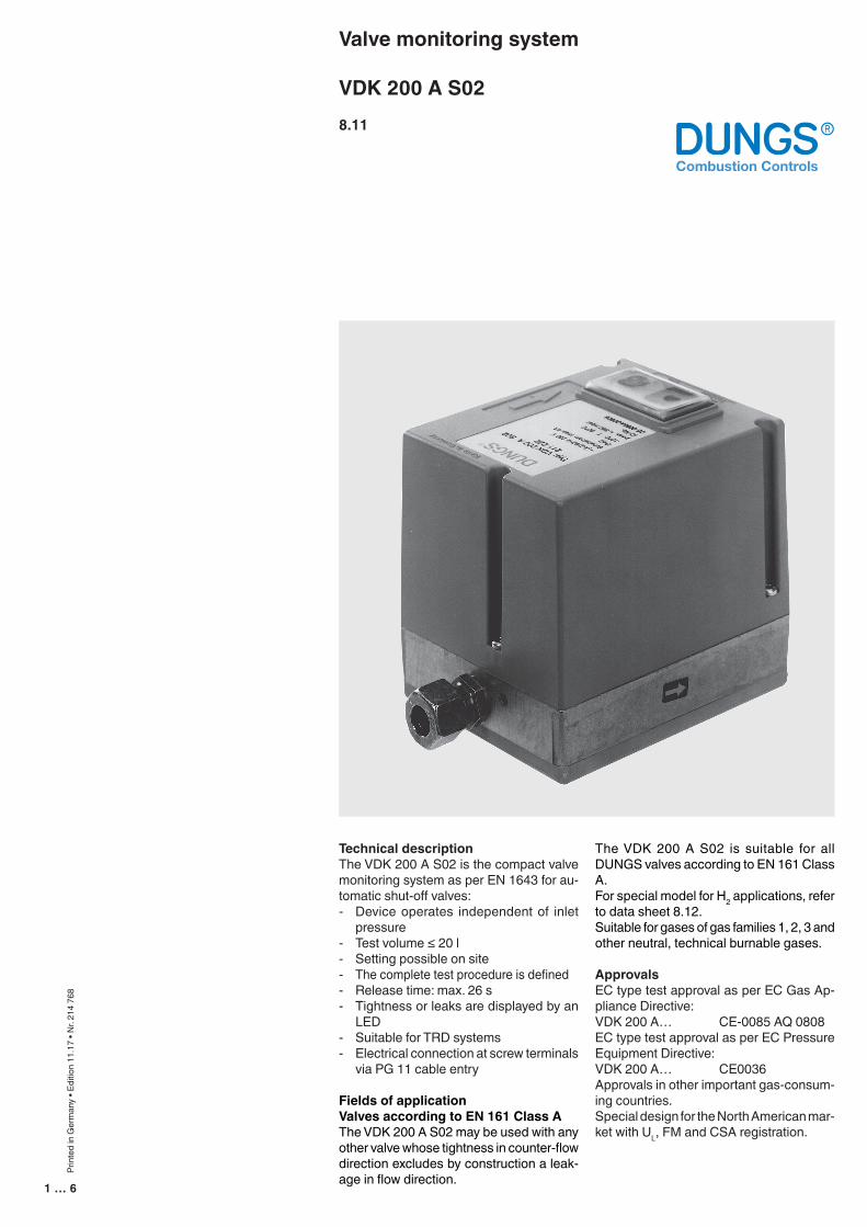
Valve monitoring system
VDK 200 A S028.11
The VDK 200 A S02 is suitable for all DUNGS valves according to EN 161 Class A.For special model for H2 applications, refer to data sheet 8.12.Suitable for gases of gas families 1, 2, 3 and other neutral, technical burnable gases.
ApprovalsEC type test approval as per EC Gas Ap-pliance Directive:VDK 200 A… CE-0085 AQ 0808EC type test approval as per EC Pressure Equipment Directive:VDK 200 A… CE0036Approvals in other important gas-consum-ing countries.Special design for the North American mar-ket with UL, FM and CSA registration.
Technical descriptionThe VDK 200 A S02 is the compact valve monitoring system as per EN 1643 for au-tomatic shut-off valves:- Device operates independent of inlet
pressure- Test volume ≤ 20 l- Setting possible on site- The complete test procedure is defined- Release time: max. 26 s- Tightness or leaks are displayed by an
LED- Suitable for TRD systems- Electrical connection at screw terminals
via PG 11 cable entry
Fields of applicationValves according to EN 161 Class AThe VDK 200 A S02 may be used with any other valve whose tightness in counter-flow direction excludes by construction a leak-age in flow direction.
2 … 6
Specifications
Operating pressure
Test volume
Pressure increase by motor pump
Rated voltage / frequency(admissible voltage range)
Power requirements
Back-up fuse (provided by customer)
Fuse installed in housing cover, re-placeable
Switching currentObserve the starting current of the motor!
Degree of protection
Ambient temperature
Release time
Interference time
Sensitivity limit
Switch-on duration of control
Max. number of test cycles
Installation position
max. 360 mbar (36 kPa)
≥ 0,4 l≤ 20,0 l
35 - 40 mbar
230 V AC -15% to -240 V +6% 50 HzFor further voltages, refer to type overview
During pumping time approx. 80 VA, in operation 20 VA
10 A fast-blow fuse or 6.3 A slow-blow fuse
Microfuse T 6.3 L 250 V; IEC-127-2/III (DIN 41 662)
Operation output Terminal 13: max. 4 AFault output Terminal 14: max. 1 A
IP 40
-10 °C to +60 °C
10…26 s, depending on test volume and inlet pressure
32 ± 3 s
50 dm3/h or 0.1 % of the burner heat load (> 500 kW)The VDK 200 A S02 can always be used with systems with a burner capacity
< 500 kW or a test volume < 6 l. If the system has a burner capacity > 500 kW or a test volume > 6 l, the VDK 200 A S02 can be used only if the burner capacity is higher than the minimum burner capacity specified in the diagram.
100 %
15/h. Wait for at least 2 minutes after carrying out more than 3 consecutive test cycles.
vertical to horizontal, not upside down
VDK 200 A S02 Valve proving system for automatic shut-off valves as per EN 161, Class A
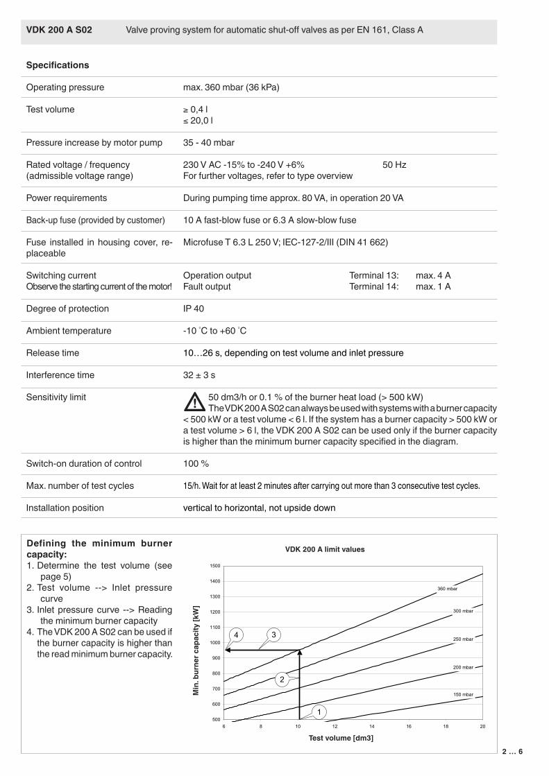
Defining the minimum burner capacity:1. Determine the test volume (see
page 5)2. Test volume --> Inlet pressure
curve3. Inlet pressure curve --> Reading
the minimum burner capacity4. The VDK 200 A S02 can be used if
the burner capacity is higher than the read minimum burner capacity.
500
600
700
800
900
1000
1100
1200
1300
1400
1500
6 8 10 12 14 16 18 20
3
2
360 mbar
250 mbar
150 mbar
4
1
300 mbar
200 mbar
Test volume [dm3]
Min
. bur
ner c
apac
ity [k
W]
VDK 200 A limit values
3 … 6
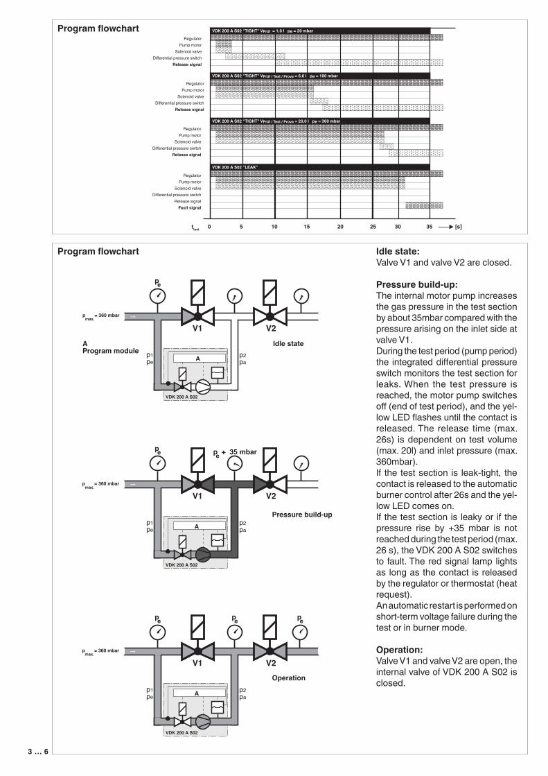
Program flowchart Idle state:Valve V1 and valve V2 are closed.
Pressure build-up:The internal motor pump increases the gas pressure in the test section by about 35mbar compared with the pressure arising on the inlet side at valve V1.During the test period (pump period) the integrated differential pressure switch monitors the test section for leaks. When the test pressure is reached, the motor pump switches off (end of test period), and the yel-low LED flashes until the contact is released. The release time (max. 26s) is dependent on test volume (max. 20l) and inlet pressure (max. 360mbar).If the test section is leak-tight, the contact is released to the automatic burner control after 26s and the yel-low LED comes on.If the test section is leaky or if the pressure rise by +35 mbar is not reached during the test period (max. 26 s), the VDK 200 A S02 switches to fault. The red signal lamp lights as long as the contact is released by the regulator or thermostat (heat request).An automatic restart is performed on short-term voltage failure during the test or in burner mode.
Operation:Valve V1 and valve V2 are open, the internal valve of VDK 200 A S02 is closed.
Program flowchart
RegulatorPump motor
Solenoid valveDifferential pressure switch
Release signal
RegulatorPump motor
Solenoid valveDifferential pressure switch
Release signalFault signal
VDK 200 A S02 "LEAK"
VDK 200 A S02 "TIGHT" VPrüf = 1,0 l pe = 20 mbar
VDK 200 A S02 "TIGHT" VPrüf / Test / Prova = 6,0 l pe = 100 mbar
VDK 200 A S02 "TIGHT" VPrüf / Test / Prova = 20,0 l pe = 360 mbar
RegulatorPump motor
Solenoid valveDifferential pressure switch
Release signal
RegulatorPump motor
Solenoid valveDifferential pressure switch
Release signal
0 5 10 15 20 25 [s]30 35ttest
4 … 6
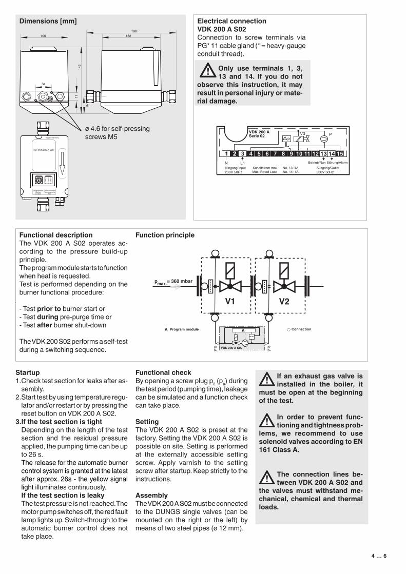
Dimensions [mm]
DérangementBloccoLockout
FonctionnementFunzionamento
Run
Störung Betrieb
Typ: VDK 200 A S02
106196
132
142
11
3734
Made in Germany
Startup1. Check test section for leaks after as-
sembly.2. Start test by using temperature regu-
lator and/or restart or by pressing the reset button on VDK 200 A S02.
3.If the test section is tight Depending on the length of the test
section and the residual pressure applied, the pumping time can be up to 26 s.
The release for the automatic burner control system is granted at the latest after approx. 26s - the yellow signal light illuminates continuously.
If the test section is leaky The test pressure is not reached. The
motor pump switches off, the red fault lamp lights up. Switch-through to the automatic burner control does not take place.
Functional checkBy opening a screw plug p2 (pa) during the test period (pumping time), leakage can be simulated and a function check can take place.
SettingThe VDK 200 A S02 is preset at the factory. Setting the VDK 200 A S02 is possible on site. Setting is performed at the externally accessible setting screw. Apply varnish to the setting screw after startup. Keep strictly to the instructions.
AssemblyThe VDK 200 A S02 must be connected to the DUNGS single valves (can be mounted on the right or the left) by means of two steel pipes (ø 12 mm).
If an exhaust gas valve is installed in the boiler, it
must be open at the beginning of the test.
In order to prevent func-tioning and tightness prob-
lems, we recommend to use solenoid valves according to EN 161 Class A.
The connection lines be-tween VDK 200 A S02 and
the valves must withstand me-chanical, chemical and thermal loads.
Electrical connectionVDK 200 A S02Connection to screw terminals via PG* 11 cable gland (* = heavy-gauge conduit thread).
Only use terminals 1, 3, 13 and 14. If you do not
observe this instruction, it may result in personal injury or mate-rial damage.
Function principleFunctional descriptionThe VDK 200 A S02 operates ac-cording to the pressure build-up principle.The program module starts to function when heat is requested.Test is performed depending on the burner functional procedure:
- Test prior to burner start or- Test during pre-purge time or- Test after burner shut-down
The VDK 200 S02 performs a self-test during a switching sequence.
ø 4.6 for self-pressing screws M5
5 … 6
Using the VDK 200 A S02 at DUNGS individual solenoid valves .../5We recommend the use of the connec-tion kit, Order No. 231 776, for mounting the VDK 200 A S02 on the valves Rp 1 1/2 to Rp 2 and or/ DN 40 to DN 50.We recommend the use of the connec-tion kit, Order No. 231 777, for mounting the VDK 200 A S02 on the valves DN 65 to DN 150.
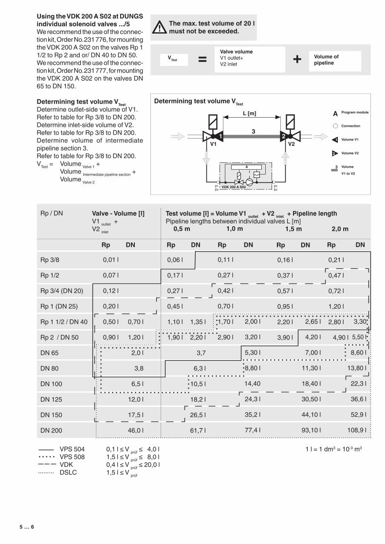
Determining test volume VTestDetermine outlet-side volume of V1.Refer to table for Rp 3/8 to DN 200.Determine inlet-side volume of V2.Refer to table for Rp 3/8 to DN 200.Determine volume of intermediate pipeline section 3.Refer to table for Rp 3/8 to DN 200.VTest = Volume Valve 1 + Volume Intermediate pipeline section + Volume Valve 2
VTest = Valve volumeV1 outlet+V2 inlet + Volume of
pipeline
Determining test volume VTest
The max. test volume of 20 l must not be exceeded.
Valve - Volume [l]V1 outlet +V2 inlet
Test volume [l] = Volume V1 outlet + V2 inlet + Pipeline lengthPipeline lengths between individual valves L [m]
Rp / DN
Rp 3/8
Rp 1/2
Rp 3/4 (DN 20)
Rp 1 (DN 25)
Rp 1 1/2 / DN 40
Rp 2 / DN 50
DN 65
DN 80
DN 100
DN 125
DN 150
DN 200
0,5 m
0,06 l
0,17 l
0,27 l
0,45 l
1,10 l
1,90 l
0,01 l
0,07 l
0,12 l
0,20 l
0,50 l
0,90 l
Rp DN Rp DN
1,5 m
0,16 l
0,37 l
0,57 l
0,95 l
2,20 l
3,90 l
Rp DN
1,0 m
0,11 l
0,27 l
0,42 l
0,70 l
1,70 l
2,90 l
Rp DN Rp DN
2,00 l
3,20 l
5,30 l
8,80 l
14,40
24,3 l
35,2 l
77,4 l
2,65 l
4,20 l
7,00 l
11,30 l
18,40 l
30,50 l
44,10 l
93,10 l
3,30
5,50 l
8,60 l
13,80 l
22,3 l
36,6 l
52,9 l
108,9 l
2,0 m
0,21 l
0,47 l
0,72 l
1,20 l
2,80 l
4,90 l
1,35 l
2,20 l
3,7
6,3 l
10,5 l
18,2 l
26,5 l
61,7 l
0,70 l
1,20 l
2,0 l
3,8
6,5 l
12,0 l
17,5 l
46,0 l
VPS 504 0,1 l ≤ V prüf ≤ 4,0 l 1 l = 1 dm3 = 10-3 m3
VPS 508 1,5 l ≤ V prüf ≤ 8,0 l VDK 0,4 l ≤ V prüf ≤ 20,0 l ········· DSLC 1,5 l ≤ V prüf
6 … 6
Valve monitoring system
VDK 200 A S02
We reserve the right to make any changes in the interest of technical progress.
Head Offices and FactoryKarl Dungs GmbH & Co. KGKarl-Dungs-Platz 1 D-73660 Urbach, GermanyTelephone +49 (0)7181-804-0Fax +49 (0)7181-804-166
Postal addressKarl Dungs GmbH & Co. KGPostfach 12 29D-73602 Schorndorf, Germanye-mail [email protected] www.dungs.com
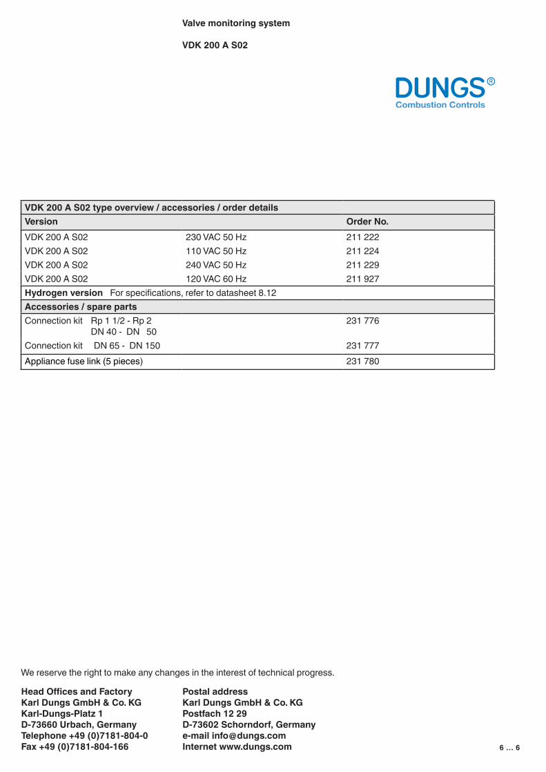
VDK 200 A S02 type overview / accessories / order detailsVersion Order No.VDK 200 A S02 230 VAC 50 Hz 211 222VDK 200 A S02 110 VAC 50 Hz 211 224VDK 200 A S02 240 VAC 50 Hz 211 229VDK 200 A S02 120 VAC 60 Hz 211 927Hydrogen version For specifications, refer to datasheet 8.12Accessories / spare partsConnection kit Rp 1 1/2 - Rp 2 DN 40 - DN 50
231 776
Connection kit DN 65 - DN 150 231 777Appliance fuse link (5 pieces) 231 780
![E u d u / u l l DK í õ r í & o µ ] v v vDK í õ r í ] & o ... · d u À ] v l vDK í õ r í > ] Ì } o u vDK í õ r í / u l l DK í õ r í & o µ ] v v vDK í õ r í](https://img.pdfslide.us/doc/110x75/5f7bc92517496b0fbb1c67af/e-u-d-u-u-l-l-dk-r-o-v-v-vdk-r-o-d-u.jpg)