Embed Size (px)
Citation preview
Computers and Geotechnics xxx (2011) xxx–xxx
Contents lists available at ScienceDirect
Computers and Geotechnics
journal homepage: www.elsevier .com/locate /compgeo
Technical Communication
Validation study of the distinct lattice spring model (DLSM) on P-wavepropagation across multiple parallel joints
J.B. Zhu a,⇑, G.F. Zhao b,c, X.B. Zhao d, J. Zhao a
a Ecole Polytechnique Fédérale de Lausanne (EPFL), Laboratory for Rock Mechanics (LMR), EPFL–ENAC–IIC–LMR, Station 18, CH-1015 Lausanne, Switzerlandb School of Civil and Environmental Engineering, The University of New South Wales, Sydney, NSW 2052, Australiac State Key Laboratory for Geomechanics and Deep Underground Engineering, China University of Mining and Technology, Xuzhou, Jiangsu 221116, Chinad NJU-ECE Institute for Underground Space and Geo-environment, School of Earth Sciences and Engineering, Nanjing University, Nanjing 210093, China
a r t i c l e i n f o
Article history:Received 16 August 2010Received in revised form 10 December 2010Accepted 10 December 2010Available online xxxx
Keywords:Distinct lattice spring modelUDECVirtual wave sourceWave propagationRock joint
0266-352X/$ - see front matter � 2010 Elsevier Ltd. Adoi:10.1016/j.compgeo.2010.12.002
⇑ Corresponding author. Tel.: +41 21 693 5387; faxE-mail address: [email protected] (J.B. Zhu).
Please cite this article in press as: Zhu JB et al. Vjoints. Comput Geotech (2011), doi:10.1016/j.co
a b s t r a c t
A validation study of the distinct lattice spring model (DLSM) for wave propagation problems is per-formed. DLSM is a microstructure-based numerical model, which is meshless and has advantages in mod-elling dynamic problems where stress wave propagation is important. To verify the applicability of DLSMto modelling wave propagation through a discontinuous medium, the virtual wave source (VWS) methodis used to obtain analytical solutions for wave propagation across a jointed rock mass. Numerical mod-elling results of the commercial code UDEC are selected as the reference. The effects of particle sizeand lattice rotation angle on wave propagation are first studied. Then, the results of wave transmissionacross a single joint with a different joint stiffness and across multiple parallel joints with different jointspacings are derived with DLSM, UDEC and VWS. These results are in good agreement with each other.Therefore, the capability of DLSM to model P-wave propagation across jointed rock mass is verified,which provides confidence for the further application of DLSM to modelling more complex problems.
� 2010 Elsevier Ltd. All rights reserved.
1. Introduction
Joints can significantly influence wave propagation through arock mass. Analytical and experimental studies on wave propaga-tion across one joint set have been extensively studied [1–4], byfocusing on the effects of joint stiffness, incident angle, numberof joints and joint spacing on wave propagation. Recently, com-bined with the equivalent medium model, Li et al. [5] introduceda new concept of virtual wave source (VWS) to study wave propa-gation across a joint set, where multiple wave reflections amongjoints were taken into account.
Compared with theoretical and experimental studies, numericalmodelling provides a convenient, economical approach to studywave propagation across a jointed rock mass, especially for compli-cated cases where theoretical solutions are impossible to obtainand experiments are difficult to conduct. The representation ofjoints is a key difficulty in numerical modelling. In the finite ele-ment method (FEM), joints are often treated as individual elementscalled joint elements [6,7]. Boundary interfaces are often used tomodel joints with the FEM and boundary element method (BEM)[8] or between BEMs [9,10]. Joints are treated as slide lines in thefinite difference method (FDM) [11]. These treatments are applica-
ll rights reserved.
: +41 21 693 4153.
alidation study of the distinct lampgeo.2010.12.002
ble only when the number of joints and their displacement aresmall. In the discrete element method (DEM), a rock mass is repre-sented as an assembly of discrete blocks and joints as interfaces be-tween the blocks [12]. The universal distinct element code (UDEC),which is a 2D DEM-based numerical program, has been widelyadopted to study wave propagation across jointed rock masses. Le-mos [13] performed a study on S-wave attenuation across a singlejoint with Coulomb slip behaviour using UDEC. Brady et al. [14]performed UDEC modelling on the slip of a single joint under anexplosive line source. Chen [15] verified the capability of UDECto model the responses of jointed rock masses under explosionloading. Zhao et al. [16] carried out numerical studies of P-wavepropagation across multiple non-linearly deformable joints withUDEC.
In the present study, a newly developed numerical code, thedistinct lattice spring model (DLSM), was used to study normallyincident wave propagation across a joint set. DLSM is a microstruc-ture-based numerical model. Compared with traditional numericalmethods, DLSM has the following advantages in modelling wavepropagation problems:
(1) discontinuities are easy to implement for both the weakmaterial layer and virtual joint plane method;
(2) the computational model is easy to generate due to theadvantage of the meshless properties of DLSM;
ttice spring model (DLSM) on P-wave propagation across multiple parallel
2 J.B. Zhu et al. / Computers and Geotechnics xxx (2011) xxx–xxx
(3) DLSM has potential to model continuum–discontinuumwave propagation problems, e.g., wave induced damageand the influence of fracturing on the wave propagationprocess.
The DLSM can be viewed as a meshless method like EFG andFPM, but with similarities to DEM. Compared with the particlebased DEM, the DLSM can directly use macroscopic parameterswithout calibration process, which is regarded as the main advan-tage over other discrete element based methods. Moreover, DLSMalso has advantages over existing meshless methods, e.g., EFG, FPMand SPH, on stability, integration requirement and convenience todeal with heterogeneity problems. Due to the meshless and naturaldiscrete properties of DLSM, it is suitable for dynamic fracturingsimulation.
In this paper, the virtual wave source, which is originated butdifferent from the method used by Li et al. [5], was used to obtainthe analytical solutions. The commercial code UDEC was used toobtain the reference numerical solutions. The objective of the pa-per is to compare the results of DLSM with corresponding resultsfrom UDEC and analytical solutions and therefore to verify theapplicability of DLSM in modelling wave propagation acrossjointed rock masses.
2. The distinct lattice spring model (DLSM)
2.1. The model
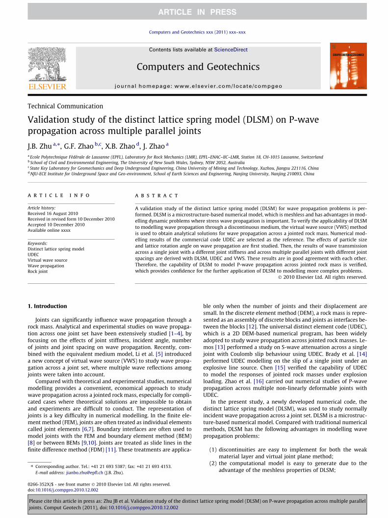
The DLSM [17,18] is a microstructure-based numerical modelbased on the Realistic Multidimensional Inter Bond (RMIB) model[19], which is an extension of the Virtual Multidimensional InterBond (VMIB) model [20]. In DLSM, materials are discretised intomass particles linked through distributed bonds (see Fig. 1a).Whenever two particles are detected in contact, they are linked to-gether through bonds between their centre points. Due to the ex-plicit considerations of the material microstructure, the modelhas the potential to generate more realistic modelling of material
Fig. 1. (a) Physical model and (b) calculation cycle of DLSM.
Please cite this article in press as: Zhu JB et al. Validation study of the distinct lajoints. Comput Geotech (2011), doi:10.1016/j.compgeo.2010.12.002
failure behaviour than a phenomenological model does. Based onCauchy–Born rules and the hyper-elastic theory, the relationshipbetween the micromechanical parameters and the macro materialconstants can be obtained as follows [21]:
kn ¼3E
a3Dð1� 2vÞ ð1Þ
ks ¼3ð1� 4vÞE
a3Dð1þ vÞð1� 2vÞ ð2Þ
where kn is the spring normal stiffness, ks is the shear stiffness, E isthe Young’s modulus, v is the Poisson ratio and a3D is the micro-structure geometry coefficient, which is obtained from
a3D ¼P
l2i
Vð3Þ
where li is the original length of the ith bond and V is the volume ofthe geometry model.
The particles and springs comprise a whole system, which rep-resents the material. For this system, the equation of motion is ex-pressed as
½K�uþ ½C� _uþ ½M�€u ¼ FðtÞ ð4Þ
where u represents the particle displacement vector, [M] is thediagonal mass matrix, [C] is the damping matrix and F(t) is the vec-tor of external forces on particles. The motion equations of the par-ticle system are solved through an explicit central finite differencesscheme. The calculation cycle is illustrated in Fig. 1b. The details ofthe implementation and verification of DLSM can be found in[17,18].
2.2. Representation of discontinuities in DLSM
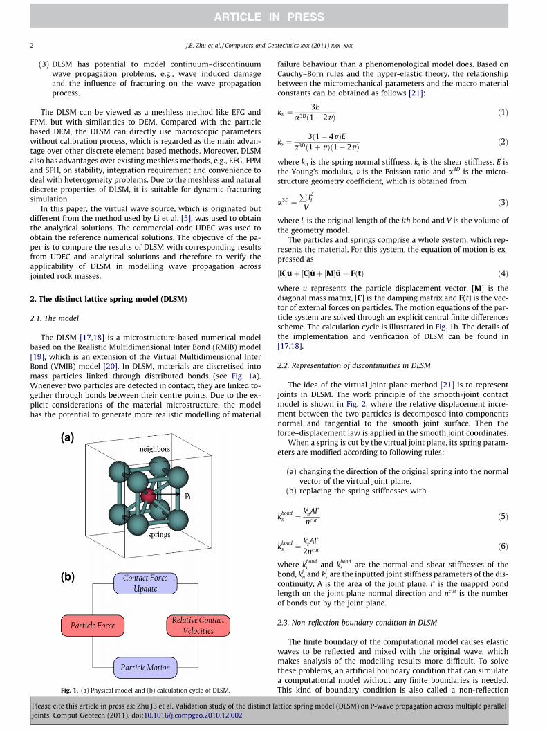
The idea of the virtual joint plane method [21] is to representjoints in DLSM. The work principle of the smooth-joint contactmodel is shown in Fig. 2, where the relative displacement incre-ment between the two particles is decomposed into componentsnormal and tangential to the smooth joint surface. Then theforce–displacement law is applied in the smooth joint coordinates.
When a spring is cut by the virtual joint plane, its spring param-eters are modified according to following rules:
(a) changing the direction of the original spring into the normalvector of the virtual joint plane,
(b) replacing the spring stiffnesses with
kbondn ¼ kj
nAl�
ncutð5Þ
kbonds ¼ kj
sAl�
2ncutð6Þ
where kbondn and kbond
s are the normal and shear stiffnesses of thebond, kj
n and kjs are the inputted joint stiffness parameters of the dis-
continuity, A is the area of the joint plane, l� is the mapped bondlength on the joint plane normal direction and ncut is the numberof bonds cut by the joint plane.
2.3. Non-reflection boundary condition in DLSM
The finite boundary of the computational model causes elasticwaves to be reflected and mixed with the original wave, whichmakes analysis of the modelling results more difficult. To solvethese problems, an artificial boundary condition that can simulatea computational model without any finite boundaries is needed.This kind of boundary condition is also called a non-reflection
ttice spring model (DLSM) on P-wave propagation across multiple parallel
Macro joint plane
n
A
x
zy
x
y
Fig. 2. Virtual joint plane method in DLSM to represent discontinuity.
J.B. Zhu et al. / Computers and Geotechnics xxx (2011) xxx–xxx 3
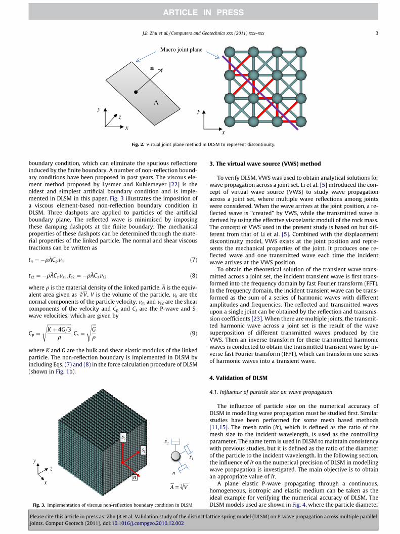
boundary condition, which can eliminate the spurious reflectionsinduced by the finite boundary. A number of non-reflection bound-ary conditions have been proposed in past years. The viscous ele-ment method proposed by Lysmer and Kuhlemeyer [22] is theoldest and simplest artificial boundary condition and is imple-mented in DLSM in this paper. Fig. 3 illustrates the imposition ofa viscous element-based non-reflection boundary condition inDLSM. Three dashpots are applied to particles of the artificialboundary plane. The reflected wave is minimised by imposingthese damping dashpots at the finite boundary. The mechanicalproperties of these dashpots can be determined through the mate-rial properties of the linked particle. The normal and shear viscoustractions can be written as
tn ¼ �q�ACpvn ð7Þ
ts2 ¼ �q�ACsvs1; ts2 ¼ �q�ACsv s2 ð8Þ
where q is the material density of the linked particle, �A is the equiv-alent area given as
ffiffiffiffiV3p
, V is the volume of the particle, vn are thenormal components of the particle velocity, vs1 and vs2 are the shearcomponents of the velocity and Cp and Cs are the P-wave and S-wave velocities, which are given by
Cp ¼
ffiffiffiffiffiffiffiffiffiffiffiffiffiffiffiffiffiffiffiffiffiK þ 4G=3
q
s;Cs ¼
ffiffiffiffiGq
sð9Þ
where K and G are the bulk and shear elastic modulus of the linkedparticle. The non-reflection boundary is implemented in DLSM byincluding Eqs. (7) and (8) in the force calculation procedure of DLSM(shown in Fig. 1b).
1s
2s
n3A V=
n
1s
2s
x
zy
Fig. 3. Implementation of viscous non-reflection boundary condition in DLSM.
Please cite this article in press as: Zhu JB et al. Validation study of the distinct lajoints. Comput Geotech (2011), doi:10.1016/j.compgeo.2010.12.002
3. The virtual wave source (VWS) method
To verify DLSM, VWS was used to obtain analytical solutions forwave propagation across a joint set. Li et al. [5] introduced the con-cept of virtual wave source (VWS) to study wave propagationacross a joint set, where multiple wave reflections among jointswere considered. When the wave arrives at the joint position, a re-flected wave is ‘‘created’’ by VWS, while the transmitted wave isderived by using the effective viscoelastic moduli of the rock mass.The concept of VWS used in the present study is based on but dif-ferent from that of Li et al. [5]. Combined with the displacementdiscontinuity model, VWS exists at the joint position and repre-sents the mechanical properties of the joint. It produces one re-flected wave and one transmitted wave each time the incidentwave arrives at the VWS position.
To obtain the theoretical solution of the transient wave trans-mitted across a joint set, the incident transient wave is first trans-formed into the frequency domain by fast Fourier transform (FFT).In the frequency domain, the incident transient wave can be trans-formed as the sum of a series of harmonic waves with differentamplitudes and frequencies. The reflected and transmitted wavesupon a single joint can be obtained by the reflection and transmis-sion coefficients [23]. When there are multiple joints, the transmit-ted harmonic wave across a joint set is the result of the wavesuperposition of different transmitted waves produced by theVWS. Then an inverse transform for these transmitted harmonicwaves is conducted to obtain the transmitted transient wave by in-verse fast Fourier transform (IFFT), which can transform one seriesof harmonic waves into a transient wave.
4. Validation of DLSM
4.1. Influence of particle size on wave propagation
The influence of particle size on the numerical accuracy ofDLSM in modelling wave propagation must be studied first. Similarstudies have been performed for some mesh based methods[11,15]. The mesh ratio (lr), which is defined as the ratio of themesh size to the incident wavelength, is used as the controllingparameter. The same term is used in DLSM to maintain consistencywith previous studies, but it is defined as the ratio of the diameterof the particle to the incident wavelength. In the following section,the influence of lr on the numerical precision of DLSM in modellingwave propagation is investigated. The main objective is to obtainan appropriate value of lr.
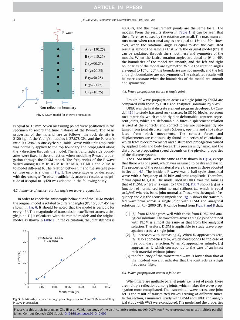
A plane elastic P-wave propagating through a continuous,homogeneous, isotropic and elastic medium can be taken as theideal example for verifying the numerical accuracy of DLSM. TheDLSM models used are shown in Fig. 4, where the particle diameter
ttice spring model (DLSM) on P-wave propagation across multiple parallel
x
y
z
P-wave
Non-reflection boundary
A (y=130.25)
B (y=110.25)
C (y=90.25)
D (y=70.25)
E (y=50.25)
F (y=30.25)
G (y=10.25)
Fig. 4. DLSM model for P-wave propagation.
4 J.B. Zhu et al. / Computers and Geotechnics xxx (2011) xxx–xxx
is equal to 0.5 mm. Seven measuring points were positioned in thespecimen to record the time histories of the P-wave. The basicproperties of the material are as follows: the rock density is2120 kg/m3, the Young’s modulus is 27.878 GPa, and the Poisson’sratio is 0.2987. A one-cycle sinusoidal wave with unit amplitudewas normally applied to the top boundary and propagated alongthe y direction through the model. The left and right side bound-aries were fixed in the x-direction when modelling P-wave propa-gation through the DLSM model. The frequencies of the P-wavevaried among 0.1 MHz, 0.2 MHz, 0.5 MHz, 1.0 MHz and 2.0 MHzto model different lr. The relation between lr and the average per-centage error is shown in Fig. 5. The percentage error decreasedwith decreasing lr. To obtain sufficiently accurate results, a magni-tude of lr equal to 1/420 was adopted in the following study.
4.2. Influence of lattice rotation angle on wave propagation
In order to check the anisotropic behaviour of the DLSM model,the original model is rotated to different angles (0�, 15�, 30�, 45�) asshown in Fig. 6. It should be noted that the model is periodic forevery 45�. The magnitude of transmission coefficient across a sin-gle joint |T1| is calculated with the rotated models and the originalmodel, as shown in Table 1. In the calculation, the joint stiffness is
Erro
r (%
)
Mesh ratio (lr)
Fig. 5. Relationship between average percentage error and lr for DLSM in modellingP-wave propagation.
Please cite this article in press as: Zhu JB et al. Validation study of the distinct lajoints. Comput Geotech (2011), doi:10.1016/j.compgeo.2010.12.002
400 GPa, and the measurement points are the same for all themodels. From the results shown in Table 1, it can be seen thatthe differences caused by the rotation are small. The maximum er-rors occur when rotational angles are equal to 15� and 30�. How-ever, when the rotational angle is equal to 45�, the calculatedresult is almost the same as that with the original model (0�). Itcan be explained through the smoothness and symmetry of themodels. When the lattice rotation angles are equal to 0� or 45�,the boundaries of the model are smooth, and the left and rightboundaries of the model are symmetric. While the rotation anglesare equal to 15� or 30�, the boundaries are not smooth, and the leftand right boundaries are not symmetric. The calculated results willbe more accurate when the boundaries of the model are smoothand symmetric.
4.3. Wave propagation across a single joint
Results of wave propagation across a single joint by DLSM arecompared with those by UDEC and analytical solutions by VWS.
UDEC was the first discrete element program developed by Cun-dall [24] to study fractured rock masses. In UDEC, blocks representrock materials, which can be rigid or deformable; contacts repre-sent joints, which are deformable. A force–displacement relationis used at the contacts, and contact forces are subsequently ob-tained from joint displacements (closure, opening and slip) calcu-lated from block movements. The contact forces anddisplacements are continuously found in a series of calculations,which trace block movements and disturbance propagation causedby applied loads and body forces. This process is dynamic, and thedisturbance propagation speed depends on the physical propertiesof the discrete system.
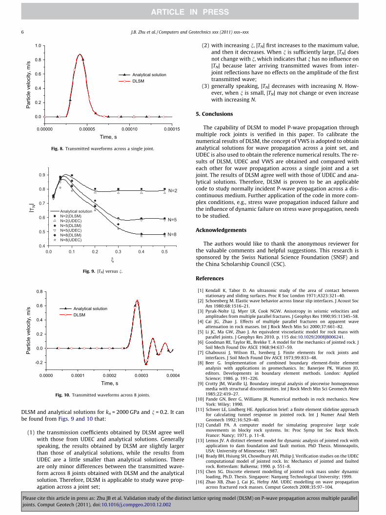
The DLSM model was the same as that shown in Fig. 4, exceptthat there was one joint, which was assumed to be dry and elastic.The properties of the rock material were the same as those adoptedin Section 4.1. The incident P-wave was a half-cycle sinusoidalwave with a frequency of 20 kHz and unit amplitude. Therefore,lr was equal to 1/420. The model used in UDEC was the same asthat of DLSM, where lr is equal to 1/24 [15]. Fig. 7 shows |T1| as afunction of normalised joint normal stiffness Kn, which is equalto kn/xZ, where kn is the joint normal stiffness, x is the angular fre-quency and Z is the acoustic impedance. Fig. 8 shows the transmit-ted waveforms across a single joint with DLSM and analyticalsolutions for kn = 2000 GPa. It can be found from Figs. 7 and 8 that:
(1) |T1| from DLSM agrees well with those from UDEC and ana-lytical solutions. The waveform across a single joint obtainedwith DLSM is almost the same as that from the analyticalsolution. Therefore, DLSM is applicable to study wave prop-agation across a single joint;
(2) |T1| increases with increasing Kn. When Kn approaches zero,|T1| also approaches zero, which corresponds to the case offree boundary reflection. When Kn approaches infinity, |T1|approaches 1, which corresponds to the case of an intactrock material without joints;
(3) the frequency of the transmitted wave is lower than that ofthe incident wave. It indicates that the joint acts as a highfrequency filter.
4.4. Wave propagation across a joint set
When there are multiple parallel joints, i.e., a set of joints, thereare multiple reflections among joints, which makes the wave prop-agation more complicated. The transmitted wave across one jointset is the result of transmitted waves arriving at different times.In this section, a numerical study with DLSM and UDEC and analyt-ical study with VWS were conducted. The model and the properties
ttice spring model (DLSM) on P-wave propagation across multiple parallel
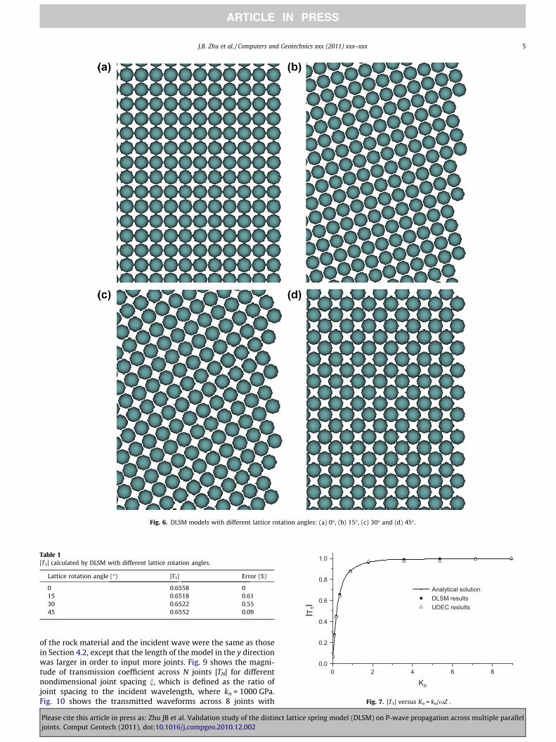
Fig. 6. DLSM models with different lattice rotation angles: (a) 0�, (b) 15�, (c) 30� and (d) 45�.
Table 1|T1| calculated by DLSM with different lattice rotation angles.
Lattice rotation angle (�) |T1| Error (%)
0 0.6558 015 0.6518 0.6130 0.6522 0.5545 0.6552 0.09
0 2 4 6 80.0
0.2
0.4
0.6
0.8
1.0
lT1l
Kn
Analytical solution DLSM results UDEC reslults
Fig. 7. |T1| versus Kn = kn/xZ .
J.B. Zhu et al. / Computers and Geotechnics xxx (2011) xxx–xxx 5
of the rock material and the incident wave were the same as thosein Section 4.2, except that the length of the model in the y directionwas larger in order to input more joints. Fig. 9 shows the magni-tude of transmission coefficient across N joints |TN| for differentnondimensional joint spacing n, which is defined as the ratio ofjoint spacing to the incident wavelength, where kn = 1000 GPa.Fig. 10 shows the transmitted waveforms across 8 joints with
Please cite this article in press as: Zhu JB et al. Validation study of the distinct lattice spring model (DLSM) on P-wave propagation across multiple paralleljoints. Comput Geotech (2011), doi:10.1016/j.compgeo.2010.12.002
0.00000 0.00005 0.00010 0.00015
0.0
0.2
0.4
0.6
0.8
1.0
Parti
cle
velo
city
, m/s
Time, s
Analytical solution DLSM
Fig. 8. Transmitted waveforms across a single joint.
Analytical solution N=2(DLSM) N=2(UDEC) N=5(DLSM) N=5(UDEC) N=8(DLSM) N=8(UDEC)
0.0 0.1 0.2 0.3 0.4 0.50.4
0.5
0.6
0.7
0.8
0.9
N=2
lTNl
ξ
N=5
N=8
Fig. 9. |TN| versus n.
0.0000 0.0001 0.0002 0.0003 0.0004
-0.2
0.0
0.2
0.4
0.6
0.8
Parti
cle
velo
city
, m/s
Time, s
Analytical solution DLSM
Fig. 10. Transmitted waveforms across 8 joints.
6 J.B. Zhu et al. / Computers and Geotechnics xxx (2011) xxx–xxx
DLSM and analytical solutions for kn = 2000 GPa and n = 0.2. It canbe found from Figs. 9 and 10 that:
(1) the transmission coefficients obtained by DLSM agree wellwith those from UDEC and analytical solutions. Generallyspeaking, the results obtained by DLSM are slightly largerthan those of analytical solutions, while the results fromUDEC are a little smaller than analytical solutions. Thereare only minor differences between the transmitted wave-form across 8 joints obtained with DLSM and the analyticalsolution. Therefore, DLSM is applicable to study wave prop-agation across a joint set;
Please cite this article in press as: Zhu JB et al. Validation study of the distinct lajoints. Comput Geotech (2011), doi:10.1016/j.compgeo.2010.12.002
(2) with increasing n, |TN| first increases to the maximum value,and then it decreases. When n is sufficiently large, |TN| doesnot change with n, which indicates that n has no influence on|TN| because later arriving transmitted waves from inter-joint reflections have no effects on the amplitude of the firsttransmitted wave;
(3) generally speaking, |TN| decreases with increasing N. How-ever, when n is small, |TN| may not change or even increasewith increasing N.
5. Conclusions
The capability of DLSM to model P-wave propagation throughmultiple rock joints is verified in this paper. To calibrate thenumerical results of DLSM, the concept of VWS is adopted to obtainanalytical solutions for wave propagation across a joint set, andUDEC is also used to obtain the reference numerical results. The re-sults of DLSM, UDEC and VWS are obtained and compared witheach other for wave propagation across a single joint and a setjoint. The results of DLSM agree well with those of UDEC and ana-lytical solutions. Therefore, DLSM is proven to be an applicablecode to study normally incident P-wave propagation across a dis-continuous medium. Further application of the code in more com-plex conditions, e.g., stress wave propagation induced failure andthe influence of dynamic failure on stress wave propagation, needsto be studied.
Acknowledgements
The authors would like to thank the anonymous reviewer forthe valuable comments and helpful suggestions. This research issponsored by the Swiss National Science Foundation (SNSF) andthe China Scholarship Council (CSC).
References
[1] Kendall K, Tabor D. An ultrasonic study of the area of contact betweenstationary and sliding surfaces. Proc R Soc London 1971;A323:321–40.
[2] Schoenberg M. Elastic wave behavior across linear slip interfaces. J Acoust SocAm 1980;68:1516–21.
[3] Pyrak-Nolte LJ, Myer LR, Cook NGW. Anisotropy in seismic velocities andamplitudes from multiple parallel fractures. J Geophys Res 1990;95:11345–58.
[4] Cai JG, Zhao J. Effects of multiple parallel fractures on apparent waveattenuation in rock masses. Int J Rock Mech Min Sci 2000;37:661–82.
[5] Li JC, Ma GW, Zhao J. An equivalent viscoelastic model for rock mass withparallel joints. J Geophys Res 2010. p. 115 doi:10.1029/2008JB006241.
[6] Goodman RE, Taylor RL, Brekke T. A model for the mechanics of jointed rock. JSoil Mech Found Div ASCE 1968;94:637–59.
[7] Ghaboussi J, Wilson EL, Isenberg J. Finite elements for rock joints andinterfaces. J Soil Mech Found Div ASCE 1973;99:833–48.
[8] Beer G. Implementation of combined boundary element-finite elementanalysis with applications in geomechanics. In: Banerjee PK, Watson JO,editors. Developments in boundary element methods. London: AppliedScience; 1986. p. 191–226.
[9] Crotty JM, Wardle LJ. Boundary integral analysis of piecewise homogeneousmedia with structural discontinuities. Int J Rock Mech Min Sci Geomech Abstr1985;22:419–27.
[10] Pande GN, Beer G, Williams JR. Numerical methods in rock mechanics. NewYork: Wiley; 1990.
[11] Schwer LE, Lindberg HE. Application brief: a finite element slideline approachfor calculating tunnel response in jointed rock. Int J Numer Anal MethGeomech 1992;16:529–40.
[12] Cundall PA. A computer model for simulating progressive large scalemovements in blocky rock systems. In: Proc Symp Int Soc Rock Mech.France: Nancy; 1971. p. 11–8.
[13] Lemos JV. A distinct element model for dynamic analysis of jointed rock withapplication to dam foundation and fault motion. PhD Thesis. Minneapolis,USA: University of Minnesota; 1987.
[14] Brady BH, Hsiung SH, Chowdhury AH, Philip J. Verification studies on the UDECcomputational model of jointed rock. In: Mechanics of jointed and faultedrock. Rotterdam: Balkema; 1990. p. 551–8.
[15] Chen SG. Discrete element modelling of jointed rock mass under dynamicloading, Ph.D. Thesis. Singapore: Nanyang Technological University; 1999.
[16] Zhao XB, Zhao J, Cai JG, Hefny AM. UDEC modelling on wave propagationacross fractured rock masses. Comput Geotech 2008;35:97–104.
ttice spring model (DLSM) on P-wave propagation across multiple parallel

J.B. Zhu et al. / Computers and Geotechnics xxx (2011) xxx–xxx 7
[17] Zhao GF, Fang J, Zhao J. A 3D distinct lattice spring model for elasticity anddynamic failure. Int J Numer Anal Meth Geomech 2010 doi:10.1002/nag.930.
[18] Zhao GF, Zhao J. Microscopic numerical modelling of the dynamic strength ofbrittle rock. In: Ma GW, Zhou YX, editors. Analysis of discontinuousdeformation: new developments and applications. Singapore: ResearchPublishing; 2009. p. 633–40.
[19] Zhao GF, Fang J, Zhao J. A new microstructure-based constitutive model forfailure modelling of elastic continuum. Eur J Mech Solid 2009 (submitted).
[20] Zhang ZN, Ge XR. Micromechanical consideration of tensile crack behaviorbased on virtual internal bond in contrast to cohesive stress. Theor Appl FractMech 2005;43:342–59.
Please cite this article in press as: Zhu JB et al. Validation study of the distinct lajoints. Comput Geotech (2011), doi:10.1016/j.compgeo.2010.12.002
[21] Zhao GF Development of micro–macro continuum–discontinuum couplednumerical method. PhD thesis. Ecole Polytechnique Fédérale de Lausanne(EPFL). Switzerland: Lausanne; 2010.
[22] Lysmer J, Kuhlemeyer RL. Finite dynamic model for infinite media. J Eng MechDiv ASCE 1969;95:859–77.
[23] Pyrak-Nolte LJ, Myer LR, Cook NGW. Transmission of seismic waves acrosssingle natural fractures. J Geophys Res 1990;95:8617–38.
[24] Cundall PA. UDEC�a generalized distinct element program for modellingjointed rock. Report PCAR-1-80, Peter Cundall Associates, US Army, EuropeanResearch Office, London, Contract DAJA37-79-C-0548; 1980.
ttice spring model (DLSM) on P-wave propagation across multiple parallel