Embed Size (px)
Citation preview

USER'S GUIDE
Vaisala Structural Humidity Measurement Kit
SHM40
M211423EN-C
PUBLISHED BY
Vaisala Oyj Phone (int.): +358 9 8949 1 P.O. Box 26 Fax: +358 9 8949 2227 FI-00421 Helsinki Finland
Visit our Internet pages at www.vaisala.com.
© Vaisala 2015
No part of this manual may be reproduced in any form or by any means, electronic or mechanical (including photocopying), nor may its contents be communicated to a third party without prior written permission of the copyright holder.
The contents are subject to change without prior notice.
Local rules and regulations may vary and they shall take precedence over the information contained in this manual. Vaisala makes no representations on this manual’s compliance with the local rules and regulations applicable at any given time, and hereby disclaims any and all responsibilities related thereto.
Please observe that this manual does not create any legally binding obligations for Vaisala towards the customer or end user. All legally binding commitments and agreements are included exclusively in the applicable supply contract or Conditions of Sale.
_________________________________________________________________________________
VAISALA _________________________________________________________________________ 1
Table of Contents
CHAPTER 1 GENERAL INFORMATION ............................................................................ 5
About This Manual ................................................................... 5 Contents of This Manual ....................................................... 5 Version Information ............................................................... 6 Related Manuals ................................................................... 6 Documentation Conventions ................................................. 6
Safety ......................................................................................... 7 ESD Protection ...................................................................... 7
Recycling .................................................................................. 8 Regulatory Compliances ......................................................... 8 Trademarks ............................................................................... 8 Warranty .................................................................................... 9
CHAPTER 2 PRODUCT OVERVIEW ................................................................................ 11
Introduction to SHM40 Kit ..................................................... 11 SHM40 Kit Contents ............................................................... 12
CHAPTER 3 HUMIDITY MEASUREMENT IN CONCRETE ............................................. 15
Humidity Measurements in a Borehole ................................ 15 Measurement Depth ............................................................ 16 Humidity Profile ................................................................... 16
Maximum Humidity Levels for Coating ................................ 18 Importance of Temperature Differences .............................. 19 Preparations for Measurement ............................................. 20
Preparations for Solid Concrete .......................................... 21 Preparations for Freshly Cast Concrete .............................. 22 Inserting the Probe and Sealing the Hole ........................... 24 Alternate Sealing Materials ................................................. 27
Plastic Tubes .................................................................. 27 Rubber Plugs ................................................................. 27 Protective Covers ........................................................... 27
Performing the Measurement ............................................... 28 Ending the Measurements..................................................... 29
CHAPTER 4 USING THE HM40 INDICATOR ................................................................... 31
HM40 Indicator ........................................................................ 31 Batteries .................................................................................. 32
Battery Life .......................................................................... 33 Charging .............................................................................. 33
USER'S GUIDE ____________________________________________________________________
2 ____________________________________________________________________ M211423EN-C
Connecting the Probe ............................................................ 34 First Startup ............................................................................ 35
Initial Settings ...................................................................... 35 Quantities Explained .............................................................. 36 Screen Layout and Controls .................................................. 37
Indicators ............................................................................. 38 Numeric View ...................................................................... 38 Statistics View ..................................................................... 39 Graph View .......................................................................... 39
Hold and Tag ........................................................................... 40 Main Menu ............................................................................... 42
Tagged Points ..................................................................... 42 Graph Duration .................................................................... 43 Settings ................................................................................ 43 Calibration ........................................................................... 44 Help ..................................................................................... 44
Settings Submenu .................................................................. 45 Language ............................................................................. 45 Units..................................................................................... 45 Time & Date ......................................................................... 46 Pressure .............................................................................. 47 Reminder ............................................................................. 47 Backlight .............................................................................. 48 Battery ................................................................................. 48 Power off ............................................................................. 48 Navigation ............................................................................ 49 Rounding ............................................................................. 49 Factory Settings ................................................................... 49
CHAPTER 5 MAINTENANCE ............................................................................................ 51
Periodic Maintenance ............................................................. 51 Cleaning .............................................................................. 51 Changing the Filter .............................................................. 52 Calibration ........................................................................... 52 Calibrating the HMP40S Probe Using HMK15 Humidity Calibrator ............................................................................. 53
Repair Maintenance ................................................................ 56
CHAPTER 6 TROUBLESHOOTING .................................................................................. 57
Avoid Condensation and Rain .............................................. 57 Problem Situations ................................................................. 58 Technical Support .................................................................. 59
CHAPTER 7 TECHNICAL DATA ...................................................................................... 61
Specifications ......................................................................... 61 Spare Parts and Accessories ................................................ 63 Dimensions in mm .................................................................. 64
APPENDIX A

_________________________________________________________________________________
VAISALA _________________________________________________________________________ 3
HUMIDITY REPORT FORM ......................................................................... 65
USER'S GUIDE ____________________________________________________________________
4 ____________________________________________________________________ M211423EN-C
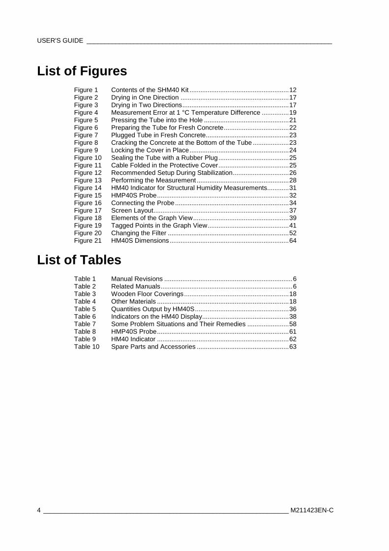
List of Figures Figure 1 Contents of the SHM40 Kit ....................................................... 12 Figure 2 Drying in One Direction ............................................................ 17 Figure 3 Drying in Two Directions ........................................................... 17 Figure 4 Measurement Error at 1 °C Temperature Difference ............... 19 Figure 5 Pressing the Tube into the Hole ............................................... 21 Figure 6 Preparing the Tube for Fresh Concrete .................................... 22 Figure 7 Plugged Tube in Fresh Concrete .............................................. 23 Figure 8 Cracking the Concrete at the Bottom of the Tube .................... 23 Figure 9 Locking the Cover in Place ....................................................... 24 Figure 10 Sealing the Tube with a Rubber Plug ....................................... 25 Figure 11 Cable Folded in the Protective Cover ....................................... 25 Figure 12 Recommended Setup During Stabilization ............................... 26 Figure 13 Performing the Measurement ................................................... 28 Figure 14 HM40 Indicator for Structural Humidity Measurements............ 31 Figure 15 HMP40S Probe ......................................................................... 32 Figure 16 Connecting the Probe ............................................................... 34 Figure 17 Screen Layout ........................................................................... 37 Figure 18 Elements of the Graph View ..................................................... 39 Figure 19 Tagged Points in the Graph View ............................................. 41 Figure 20 Changing the Filter ................................................................... 52 Figure 21 HM40S Dimensions .................................................................. 64
List of Tables Table 1 Manual Revisions ....................................................................... 6 Table 2 Related Manuals ......................................................................... 6 Table 3 Wooden Floor Coverings .......................................................... 18 Table 4 Other Materials ......................................................................... 18 Table 5 Quantities Output by HM40S .................................................... 36 Table 6 Indicators on the HM40 Display ................................................ 38 Table 7 Some Problem Situations and Their Remedies ....................... 58 Table 8 HMP40S Probe ......................................................................... 61 Table 9 HM40 Indicator ......................................................................... 62 Table 10 Spare Parts and Accessories ................................................... 63
Chapter 1 _________________________________________________________ General Information
VAISALA _________________________________________________________________________ 5
CHAPTER 1
GENERAL INFORMATION
This chapter provides general notes for the manual and the SHM40 kit.
About This Manual This manual provides information for operating, and maintaining the Vaisala Structural Humidity Measurement Kit SHM40. The manual also instructs in performing structural humidity measurements using the borehole method.
Contents of This Manual This manual consists of the following chapters:
- Chapter 1, General Information, provides general notes for the manual and the SHM40 kit.
- Chapter 2, Product Overview, introduces the features, advantages, and the product nomenclature.
- Chapter 3, Humidity Measurement in Concrete, describes the borehole method of concrete humidity measurement.
- Chapter 4, Using the HM40 Indicator, introduces the functions of the HM40 indicator and the HMP40S probe.
- Chapter 5, Maintenance, provides information that is needed in basic maintenance of the SHM40 kit.
- Chapter 6, Troubleshooting, describes common problems, their probable causes and remedies, and provides contact information for technical support.
- Chapter 7, Technical Data, provides the technical data of the SHM40 kit.
- Appendix A, Humidity Report Form, contains an example report form that can be used to record humidity measurement results.
USER'S GUIDE ____________________________________________________________________
6 ____________________________________________________________________ M211423EN-C
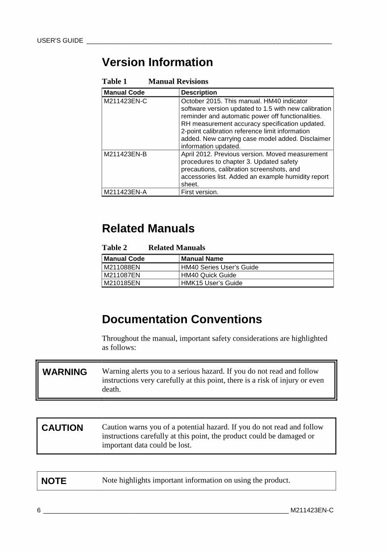
Version Information Table 1 Manual Revisions Manual Code Description M211423EN-C October 2015. This manual. HM40 indicator
software version updated to 1.5 with new calibration reminder and automatic power off functionalities. RH measurement accuracy specification updated. 2-point calibration reference limit information added. New carrying case model added. Disclaimer information updated.
M211423EN-B April 2012. Previous version. Moved measurement procedures to chapter 3. Updated safety precautions, calibration screenshots, and accessories list. Added an example humidity report sheet.
M211423EN-A First version.
Related Manuals Table 2 Related Manuals Manual Code Manual Name M211088EN HM40 Series User’s Guide M211087EN HM40 Quick Guide M210185EN HMK15 User’s Guide
Documentation Conventions Throughout the manual, important safety considerations are highlighted as follows:
WARNING Warning alerts you to a serious hazard. If you do not read and follow instructions very carefully at this point, there is a risk of injury or even death.
CAUTION Caution warns you of a potential hazard. If you do not read and follow instructions carefully at this point, the product could be damaged or important data could be lost.
NOTE Note highlights important information on using the product.
Chapter 1 _________________________________________________________ General Information
VAISALA _________________________________________________________________________ 7
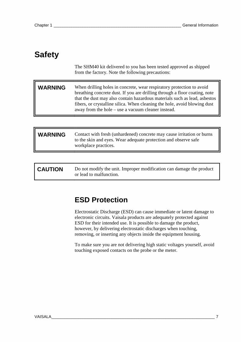
Safety The SHM40 kit delivered to you has been tested approved as shipped from the factory. Note the following precautions:
WARNING When drilling holes in concrete, wear respiratory protection to avoid breathing concrete dust. If you are drilling through a floor coating, note that the dust may also contain hazardous materials such as lead, asbestos fibers, or crystalline silica. When cleaning the hole, avoid blowing dust away from the hole – use a vacuum cleaner instead.
WARNING Contact with fresh (unhardened) concrete may cause irritation or burns to the skin and eyes. Wear adequate protection and observe safe workplace practices.
CAUTION Do not modify the unit. Improper modification can damage the product or lead to malfunction.
ESD Protection Electrostatic Discharge (ESD) can cause immediate or latent damage to electronic circuits. Vaisala products are adequately protected against ESD for their intended use. It is possible to damage the product, however, by delivering electrostatic discharges when touching, removing, or inserting any objects inside the equipment housing.
To make sure you are not delivering high static voltages yourself, avoid touching exposed contacts on the probe or the meter.

USER'S GUIDE ____________________________________________________________________
8 ____________________________________________________________________ M211423EN-C
Recycling
Recycle all applicable material.
Dispose of batteries and the unit according to statutory regulations. Do not dispose of with regular household refuse.
Regulatory Compliances The Vaisala Structural Humidity Measurement Kit SHM40 is in conformity with the provisions of the following EU directive(s):
- EMC-Directive
Conformity is shown by compliance with the following standards:
- EN 61326-1: Electrical equipment for measurement, control, and laboratory use – EMC requirements – for portable equipment.
- EN 550022: Information technology equipment – Radio disturbance characteristics – Limits and methods of measurement.
Trademarks HUMICAP® is a registered trademark of Vaisala Oyj.
Chapter 1 _________________________________________________________ General Information
VAISALA _________________________________________________________________________ 9
Warranty Visit our Internet pages for more information and our standard warranty terms and conditions: www.vaisala.com/warranty.
Please observe that any such warranty may not be valid in case of damage due to normal wear and tear, exceptional operating conditions, negligent handling or installation, or unauthorized modifications. Please see the applicable supply contract or Conditions of Sale for details of the warranty for each product.

USER'S GUIDE ____________________________________________________________________
10 ___________________________________________________________________ M211423EN-C
This page intentionally left blank.

Chapter 2 ___________________________________________________________ Product Overview
VAISALA ________________________________________________________________________ 11
CHAPTER 2
PRODUCT OVERVIEW
This chapter introduces the features, advantages, and the product nomenclature.
Introduction to SHM40 Kit Vaisala Structural Humidity Measurement Kit SHM40 is a practical tool for humidity measurement of concrete and other structures. The kit has been designed for use with the borehole method.
Main features:
- HM40 indicator - HM40 indicator with connection adapter for HMP40S probes. - Large graphical display with graphs for selected quantity and
temperature. - Outputs a wide range of quantities: RH, Td, Tw, a, x, h, T. See
section Quantities Explained on page 36. - Powered by standard AA size batteries (2 pcs). - Belt clip.
- Interchangeable HMP40S humidity and temperature probe - HMP110 probe and cable with integrated rubber plug. - Can be calibrated by a Vaisala Service Center or user calibrated
using the HMK15 humidity calibrator, for example. - Various accessories for ensuring accurate humidity measurement
using the borehole method. - Durable weatherproof case. - Conforms to ASTM standard F2170.
NOTE The HM40 indicator and HMP40S probe are also sold separately as the HM40S.
USER'S GUIDE ____________________________________________________________________
12 ___________________________________________________________________ M211423EN-C
SHM40 Kit Contents
1508-113
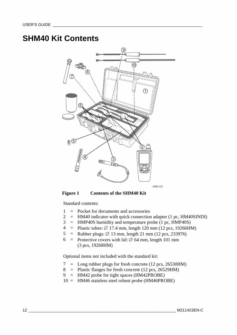
Figure 1 Contents of the SHM40 Kit
Standard contents:
1 = Pocket for documents and accessories 2 = HM40 indicator with quick connection adapter (1 pc, HM40SINDI) 3 = HMP40S humidity and temperature probe (1 pc, HMP40S) 4 = Plastic tubes: ∅ 17.4 mm, length 120 mm (12 pcs, 19266HM) 5 = Rubber plugs: ∅ 13 mm, length 21 mm (12 pcs, 233976) 6 = Protective covers with lid: ∅ 64 mm, length 101 mm
(3 pcs, 19268HM) Optional items not included with the standard kit:
7 = Long rubber plugs for fresh concrete (12 pcs, 26530HM) 8 = Plastic flanges for fresh concrete (12 pcs, 26529HM) 9 = HM42 probe for tight spaces (HM42PROBE) 10 = HM46 stainless steel robust probe (HM46PROBE)

Chapter 2 ___________________________________________________________ Product Overview
VAISALA ________________________________________________________________________ 13
You can order standard items and optional accessories from Vaisala. For the full list of accessories, see section Spare Parts and Accessories on page 63.
NOTE Vaisala recommends using multiple HMP40S probes so that they can be inserted in all measurement points and left to equalize concurrently.

USER'S GUIDE ____________________________________________________________________
14 ___________________________________________________________________ M211423EN-C
This page intentionally left blank.
Chapter 3 _____________________________________________ Humidity Measurement in Concrete
VAISALA ________________________________________________________________________ 15
CHAPTER 3
HUMIDITY MEASUREMENT IN CONCRETE
This chapter describes the borehole method of concrete humidity measurement.
Humidity Measurements in a Borehole SHM40 kit is designed for measuring humidity in concrete using the borehole method. In the borehole method, a hole is drilled to a suitable depth in the concrete structure to be measured. After the drilling, the hole is cleaned and covered, and air humidity in the hole is allowed to equalize with the humidity in the concrete. The airspace humidity will reach humidity equilibrium with the concrete in about three days. After this, the humidity measurement is made.
For successful humidity measurement using the borehole method and the SHM40 kit, the following points are vital when preparing the hole:
- The hole must be ∅ 16 mm and reach to proper depth. See section Measurement Depth on page 16.
- After drilling, the hole must be cleaned from the drilling debris. - The hole must be allowed to cool down from the drilling, and the
humidity in the concrete must be allowed to equalize with the air in the hole.
- The hole must be sealed during the equalization time. The plastic tube and rubber plug in the SHM40 kit are used for this purpose. Ideally, the probe should be inside the plastic tube during this time.
NOTE For reliable results, it is recommended to have several measurement points.
USER'S GUIDE ____________________________________________________________________
16 ___________________________________________________________________ M211423EN-C
Measurement Depth The borehole must reach deep enough into the concrete structure to provide a representative humidity condition. The correct depth of the borehole is affected by the drying conditions of the concrete structure:
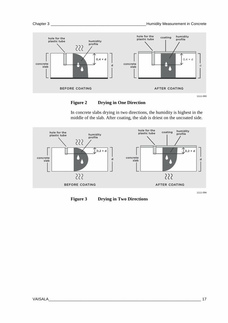
- When drying occurs from one side only, the measurement depth (d) is 40 % of the depth of a slab. See Figure 2 on page 17.
- For a concrete slab that is exposed to air on both sides, the minimum depth of measurement (d) is 20 % of the depth of the slab. See Figure 3 on page 17.
The minimum measurement depth using standard SHM40 accessories is 30 mm, maximum is 90 mm.
Humidity Profile The humidity profile of the slab depends on the drying conditions of the concrete: whether the concrete dries in one or in two directions. In concrete slabs that dry in two directions, the humidity is highest in the middle. If a floor coating is applied, the humidity spreads evenly throughout the slab until it corresponds to readings measured at the depth of approximately 20% of the slab.
In concrete slabs that dry in one direction only, the humidity is highest at the bottom. If a floor coating is applied, the humidity spreads evenly throughout the slab until it corresponds to readings measured at the depth of approximately 40% of the slab.
Chapter 3 _____________________________________________ Humidity Measurement in Concrete
VAISALA ________________________________________________________________________ 17
d
hole for theplastic tube humidity
profile
0,4 × d
concreteslab
BEFORE COATING AFTER COATING
concreteslab
hole for theplastic tube
humidityprofile
coating
d
0,4 × d
1111-093
Figure 2 Drying in One Direction
In concrete slabs drying in two directions, the humidity is highest in the middle of the slab. After coating, the slab is driest on the uncoated side.
concreteslab
hole for theplastic tube humidity
profile
d
0,2 × d
BEFORE COATING
humidityprofile
hole for theplastic tube coating
d
0,2 × d
concreteslab
AFTER COATING
1111-094
Figure 3 Drying in Two Directions
USER'S GUIDE ____________________________________________________________________
18 ___________________________________________________________________ M211423EN-C
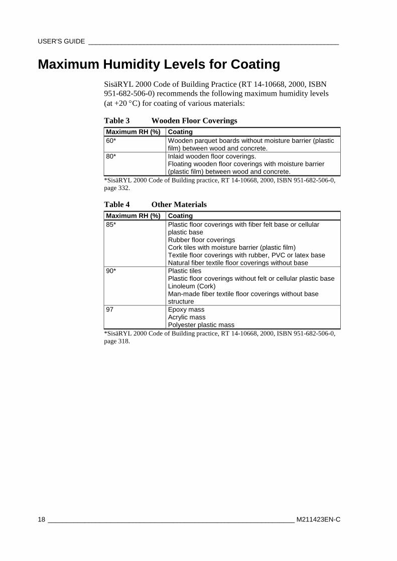
Maximum Humidity Levels for Coating SisäRYL 2000 Code of Building Practice (RT 14-10668, 2000, ISBN 951-682-506-0) recommends the following maximum humidity levels (at +20 °C) for coating of various materials:
Table 3 Wooden Floor Coverings Maximum RH (%) Coating 60* Wooden parquet boards without moisture barrier (plastic
film) between wood and concrete. 80* Inlaid wooden floor coverings.
Floating wooden floor coverings with moisture barrier (plastic film) between wood and concrete.
*SisäRYL 2000 Code of Building practice, RT 14-10668, 2000, ISBN 951-682-506-0, page 332.
Table 4 Other Materials Maximum RH (%) Coating 85* Plastic floor coverings with fiber felt base or cellular
plastic base Rubber floor coverings Cork tiles with moisture barrier (plastic film) Textile floor coverings with rubber, PVC or latex base Natural fiber textile floor coverings without base
90* Plastic tiles Plastic floor coverings without felt or cellular plastic base Linoleum (Cork) Man-made fiber textile floor coverings without base structure
97 Epoxy mass Acrylic mass Polyester plastic mass
*SisäRYL 2000 Code of Building practice, RT 14-10668, 2000, ISBN 951-682-506-0, page 318.
Chapter 3 _____________________________________________ Humidity Measurement in Concrete
VAISALA ________________________________________________________________________ 19
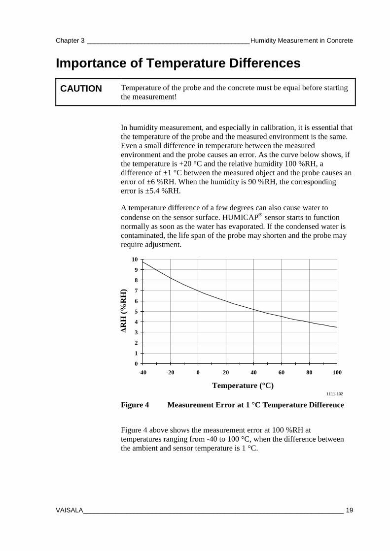
Importance of Temperature Differences
CAUTION Temperature of the probe and the concrete must be equal before starting the measurement!
In humidity measurement, and especially in calibration, it is essential that the temperature of the probe and the measured environment is the same. Even a small difference in temperature between the measured environment and the probe causes an error. As the curve below shows, if the temperature is +20 °C and the relative humidity 100 %RH, a difference of ±1 °C between the measured object and the probe causes an error of ±6 %RH. When the humidity is 90 %RH, the corresponding error is ±5.4 %RH.
A temperature difference of a few degrees can also cause water to condense on the sensor surface. HUMICAP sensor starts to function normally as soon as the water has evaporated. If the condensed water is contaminated, the life span of the probe may shorten and the probe may require adjustment.
Temperature (°C)
ΔRH
(%R
H)
0
1
2
3
4
5
6
7
8
9
10
-40 -20 0 20 40 60 80 100
1111-102
Figure 4 Measurement Error at 1 °C Temperature Difference
Figure 4 above shows the measurement error at 100 %RH at temperatures ranging from -40 to 100 °C, when the difference between the ambient and sensor temperature is 1 °C.
USER'S GUIDE ____________________________________________________________________
20 ___________________________________________________________________ M211423EN-C
Preparations for Measurement Before you can measure the humidity of concrete using the borehole method, you must prepare the borehole and wait for humidity to stabilize. The preparations can be started on a freshly cast concrete if desired.
CAUTION Before starting, read section Measurement Depth on page 16. Appropriate depth of the borehole is critical for accuracy.
NOTE For best results, insert the probe to the plastic tube immediately after you are finished preparing the borehole, and leave it to stabilize for three days.
NOTE Make sure that the tube and the probe are not colder than the concrete when inserting them: this might cause condensation on the probe and the readings can be incorrect.
Chapter 3 _____________________________________________ Humidity Measurement in Concrete
VAISALA ________________________________________________________________________ 21
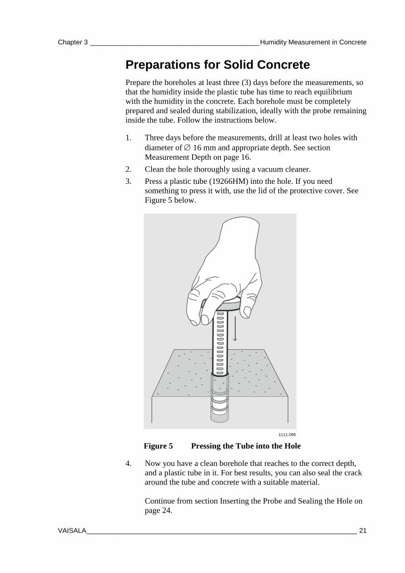
Preparations for Solid Concrete
Prepare the boreholes at least three (3) days before the measurements, so that the humidity inside the plastic tube has time to reach equilibrium with the humidity in the concrete. Each borehole must be completely prepared and sealed during stabilization, ideally with the probe remaining inside the tube. Follow the instructions below.
1. Three days before the measurements, drill at least two holes with diameter of ∅ 16 mm and appropriate depth. See section Measurement Depth on page 16.
2. Clean the hole thoroughly using a vacuum cleaner. 3. Press a plastic tube (19266HM) into the hole. If you need
something to press it with, use the lid of the protective cover. See Figure 5 below.
1111-095
Figure 5 Pressing the Tube into the Hole
4. Now you have a clean borehole that reaches to the correct depth, and a plastic tube in it. For best results, you can also seal the crack around the tube and concrete with a suitable material. Continue from section Inserting the Probe and Sealing the Hole on page 24.
USER'S GUIDE ____________________________________________________________________
22 ___________________________________________________________________ M211423EN-C
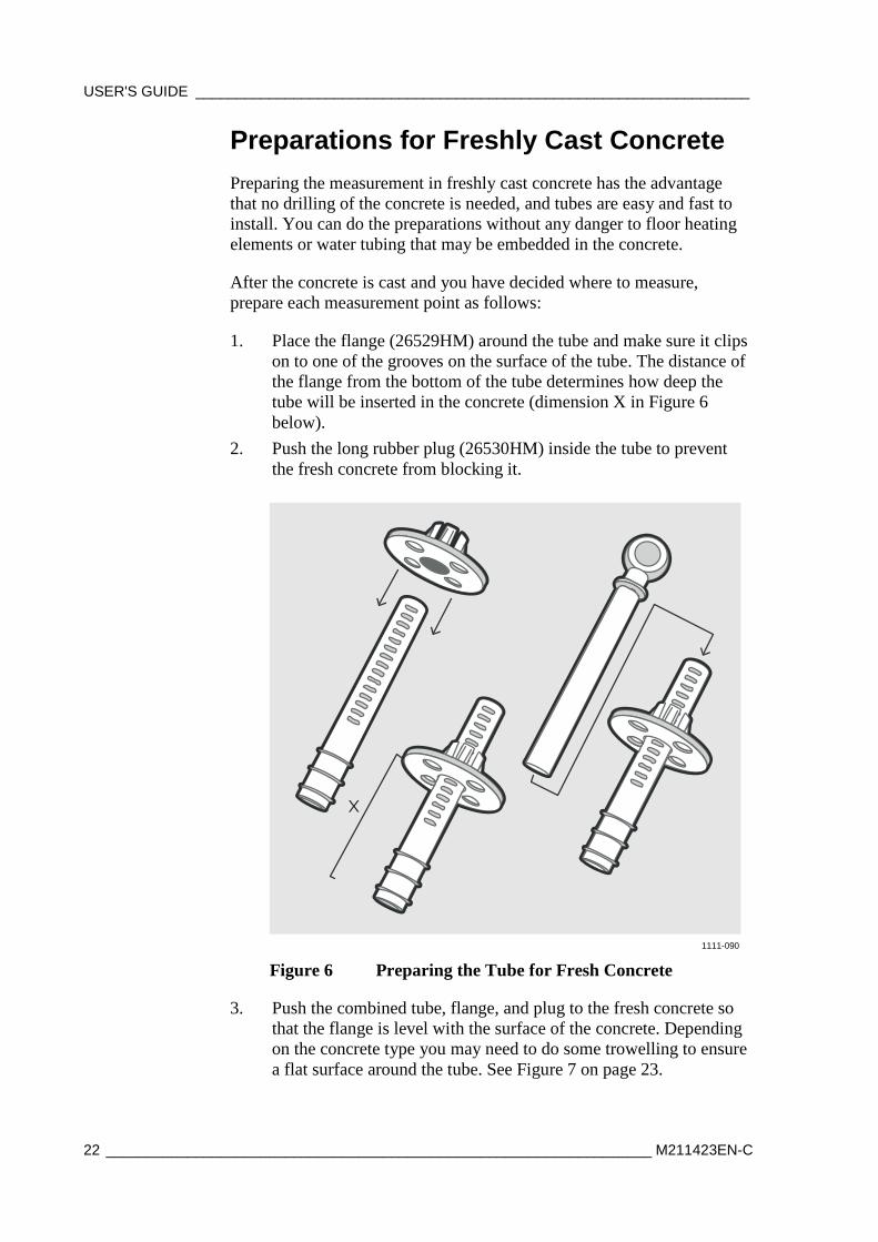
Preparations for Freshly Cast Concrete Preparing the measurement in freshly cast concrete has the advantage that no drilling of the concrete is needed, and tubes are easy and fast to install. You can do the preparations without any danger to floor heating elements or water tubing that may be embedded in the concrete.
After the concrete is cast and you have decided where to measure, prepare each measurement point as follows:
1. Place the flange (26529HM) around the tube and make sure it clips on to one of the grooves on the surface of the tube. The distance of the flange from the bottom of the tube determines how deep the tube will be inserted in the concrete (dimension X in Figure 6 below).
2. Push the long rubber plug (26530HM) inside the tube to prevent the fresh concrete from blocking it.
X
1111-090
Figure 6 Preparing the Tube for Fresh Concrete
3. Push the combined tube, flange, and plug to the fresh concrete so that the flange is level with the surface of the concrete. Depending on the concrete type you may need to do some trowelling to ensure a flat surface around the tube. See Figure 7 on page 23.
Chapter 3 _____________________________________________ Humidity Measurement in Concrete
VAISALA ________________________________________________________________________ 23
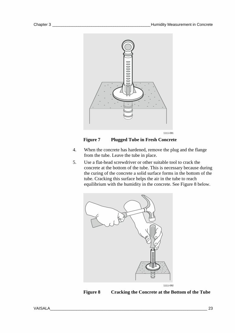
1111-091
Figure 7 Plugged Tube in Fresh Concrete
4. When the concrete has hardened, remove the plug and the flange from the tube. Leave the tube in place.
5. Use a flat-head screwdriver or other suitable tool to crack the concrete at the bottom of the tube. This is necessary because during the curing of the concrete a solid surface forms in the bottom of the tube. Cracking this surface helps the air in the tube to reach equilibrium with the humidity in the concrete. See Figure 8 below.
1111-092
Figure 8 Cracking the Concrete at the Bottom of the Tube
USER'S GUIDE ____________________________________________________________________
24 ___________________________________________________________________ M211423EN-C
6. Clean the concrete dust at the bottom of the tube using a vacuum cleaner.
7. Now you have a clean borehole that reaches to the correct depth, and a plastic tube in it. Continue from section Inserting the Probe and Sealing the Hole on page 24.
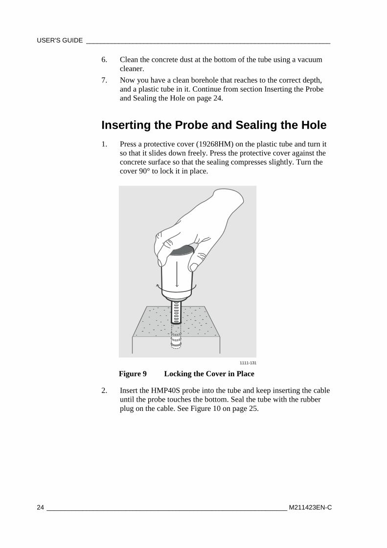
Inserting the Probe and Sealing the Hole 1. Press a protective cover (19268HM) on the plastic tube and turn it
so that it slides down freely. Press the protective cover against the concrete surface so that the sealing compresses slightly. Turn the cover 90° to lock it in place.
1111-131
Figure 9 Locking the Cover in Place
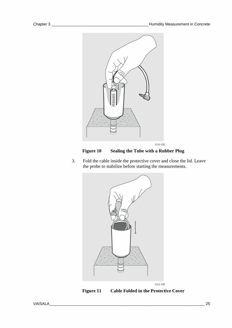
2. Insert the HMP40S probe into the tube and keep inserting the cable until the probe touches the bottom. Seal the tube with the rubber plug on the cable. See Figure 10 on page 25.
Chapter 3 _____________________________________________ Humidity Measurement in Concrete
VAISALA ________________________________________________________________________ 25
1111-132
Figure 10 Sealing the Tube with a Rubber Plug
3. Fold the cable inside the protective cover and close the lid. Leave the probe to stabilize before starting the measurements.
1111-133
Figure 11 Cable Folded in the Protective Cover
USER'S GUIDE ____________________________________________________________________
26 ___________________________________________________________________ M211423EN-C
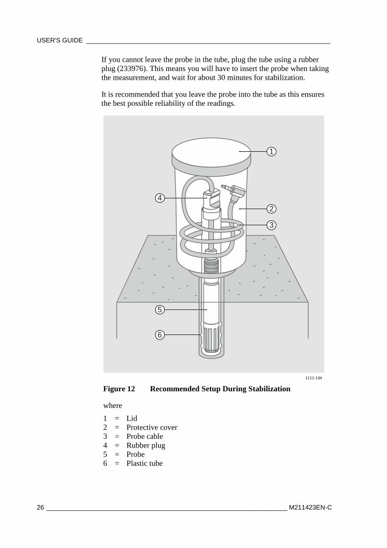
If you cannot leave the probe in the tube, plug the tube using a rubber plug (233976). This means you will have to insert the probe when taking the measurement, and wait for about 30 minutes for stabilization.
It is recommended that you leave the probe into the tube as this ensures the best possible reliability of the readings.
1
2
3
4
5
6
1111-134
Figure 12 Recommended Setup During Stabilization
where
1 = Lid 2 = Protective cover 3 = Probe cable 4 = Rubber plug 5 = Probe 6 = Plastic tube
Chapter 3 _____________________________________________ Humidity Measurement in Concrete
VAISALA ________________________________________________________________________ 27
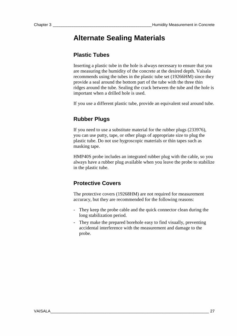
Alternate Sealing Materials
Plastic Tubes
Inserting a plastic tube in the hole is always necessary to ensure that you are measuring the humidity of the concrete at the desired depth. Vaisala recommends using the tubes in the plastic tube set (19266HM) since they provide a seal around the bottom part of the tube with the three thin ridges around the tube. Sealing the crack between the tube and the hole is important when a drilled hole is used.
If you use a different plastic tube, provide an equivalent seal around tube.
Rubber Plugs
If you need to use a substitute material for the rubber plugs (233976), you can use putty, tape, or other plugs of appropriate size to plug the plastic tube. Do not use hygroscopic materials or thin tapes such as masking tape.
HMP40S probe includes an integrated rubber plug with the cable, so you always have a rubber plug available when you leave the probe to stabilize in the plastic tube.
Protective Covers
The protective covers (19268HM) are not required for measurement accuracy, but they are recommended for the following reasons:
- They keep the probe cable and the quick connector clean during the long stabilization period.
- They make the prepared borehole easy to find visually, preventing accidental interference with the measurement and damage to the probe.
USER'S GUIDE ____________________________________________________________________
28 ___________________________________________________________________ M211423EN-C
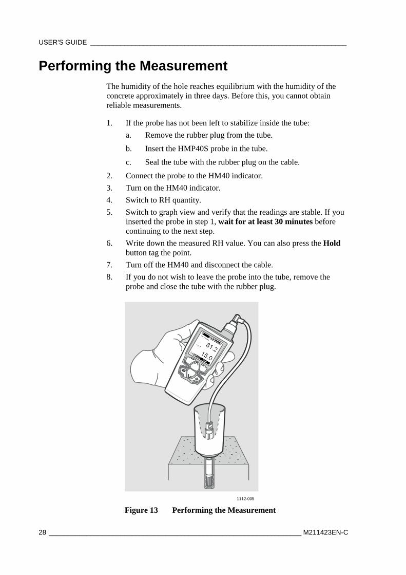
Performing the Measurement The humidity of the hole reaches equilibrium with the humidity of the concrete approximately in three days. Before this, you cannot obtain reliable measurements.
1. If the probe has not been left to stabilize inside the tube: a. Remove the rubber plug from the tube.
b. Insert the HMP40S probe in the tube.
c. Seal the tube with the rubber plug on the cable.
2. Connect the probe to the HM40 indicator. 3. Turn on the HM40 indicator. 4. Switch to RH quantity. 5. Switch to graph view and verify that the readings are stable. If you
inserted the probe in step 1, wait for at least 30 minutes before continuing to the next step.
6. Write down the measured RH value. You can also press the Hold button tag the point.
7. Turn off the HM40 and disconnect the cable. 8. If you do not wish to leave the probe into the tube, remove the
probe and close the tube with the rubber plug.
1112-005
Figure 13 Performing the Measurement
Chapter 3 _____________________________________________ Humidity Measurement in Concrete
VAISALA ________________________________________________________________________ 29
Ending the Measurements When the concrete is dry enough and measurements are no longer necessary, remove the probe and the protective cover. Pull out the plastic tube.

USER'S GUIDE ____________________________________________________________________
30 ___________________________________________________________________ M211423EN-C
This page intentionally left blank.
Chapter 4 _____________________________________________________ Using the HM40 Indicator
VAISALA ________________________________________________________________________ 31
CHAPTER 4
USING THE HM40 INDICATOR
This chapter introduces the functions of the HM40 indicator and the HMP40S probe.
HM40 Indicator
67
8
1
2
34
5
1111-136
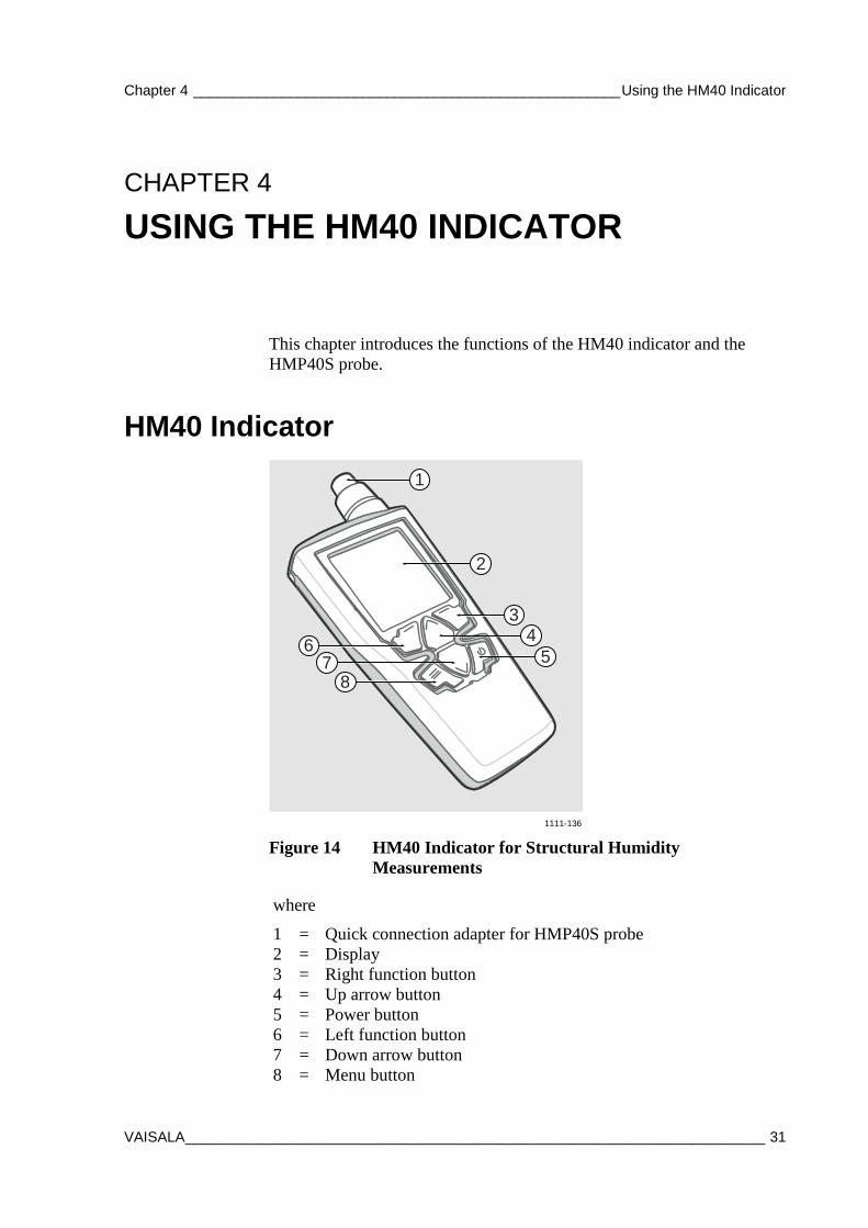
Figure 14 HM40 Indicator for Structural Humidity Measurements
where
1 = Quick connection adapter for HMP40S probe 2 = Display 3 = Right function button 4 = Up arrow button 5 = Power button 6 = Left function button 7 = Down arrow button 8 = Menu button
USER'S GUIDE ____________________________________________________________________
32 ___________________________________________________________________ M211423EN-C
1
4
3
2
1112-008
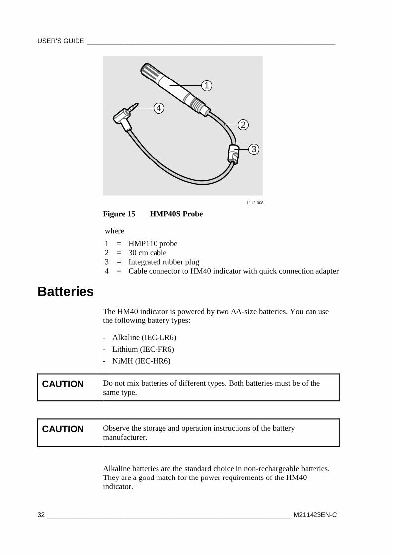
Figure 15 HMP40S Probe
where
1 = HMP110 probe 2 = 30 cm cable 3 = Integrated rubber plug 4 = Cable connector to HM40 indicator with quick connection adapter
Batteries The HM40 indicator is powered by two AA-size batteries. You can use the following battery types:
- Alkaline (IEC-LR6) - Lithium (IEC-FR6) - NiMH (IEC-HR6)
CAUTION Do not mix batteries of different types. Both batteries must be of the same type.
CAUTION Observe the storage and operation instructions of the battery manufacturer.
Alkaline batteries are the standard choice in non-rechargeable batteries. They are a good match for the power requirements of the HM40 indicator.
Chapter 4 _____________________________________________________ Using the HM40 Indicator
VAISALA ________________________________________________________________________ 33
Lithium batteries are a good choice if you need the longest battery life or best capacity in low temperatures. Lithium batteries are not rechargeable. Do not confuse them with rechargeable lithium-ion batteries, which cannot be used in HM40.
NiMH batteries are rechargeable. Two NiMH batteries are included with the USB recharger that is available from Vaisala as an option. For order codes, see section Spare Parts and Accessories on page 63.
Battery Life Typical operation time that is achieved with alkaline batteries is 100 hours. The operation time will be shorter if the display backlight is used, and if the operation environment is cold.
NOTE HM40 does not automatically power off when it is not used. To conserve batteries, turn the meter off when you are not using it or configure a suitable automatic power off delay (see Power off on page 48).
Charging The optional USB charger (Vaisala order code 229249SP) provides a convenient way to charge two NiMH batteries from any powered USB port (for example, from a laptop computer).
1. Place the rechargeable batteries in the charger and plug it into a USB port. The blue LED on top of the charger starts to blink.
2. When the LED stops blinking and stays on, the batteries are charged. The charging time is several hours for two fully discharged NiMH batteries.
If you are not using a Vaisala-supplied charger and rechargeable batteries, read and follow the manufacturer’s own charging instructions.
WARNING Do not attempt to charge non-rechargeable (alkaline or lithium) batteries! Doing so leads to a risk of battery leakage, equipment damage, and risk of explosion and/or fire.
USER'S GUIDE ____________________________________________________________________
34 ___________________________________________________________________ M211423EN-C
Connecting the Probe
NOTE It is recommended that you turn off the HM40 indicator before connecting or disconnecting the probe.
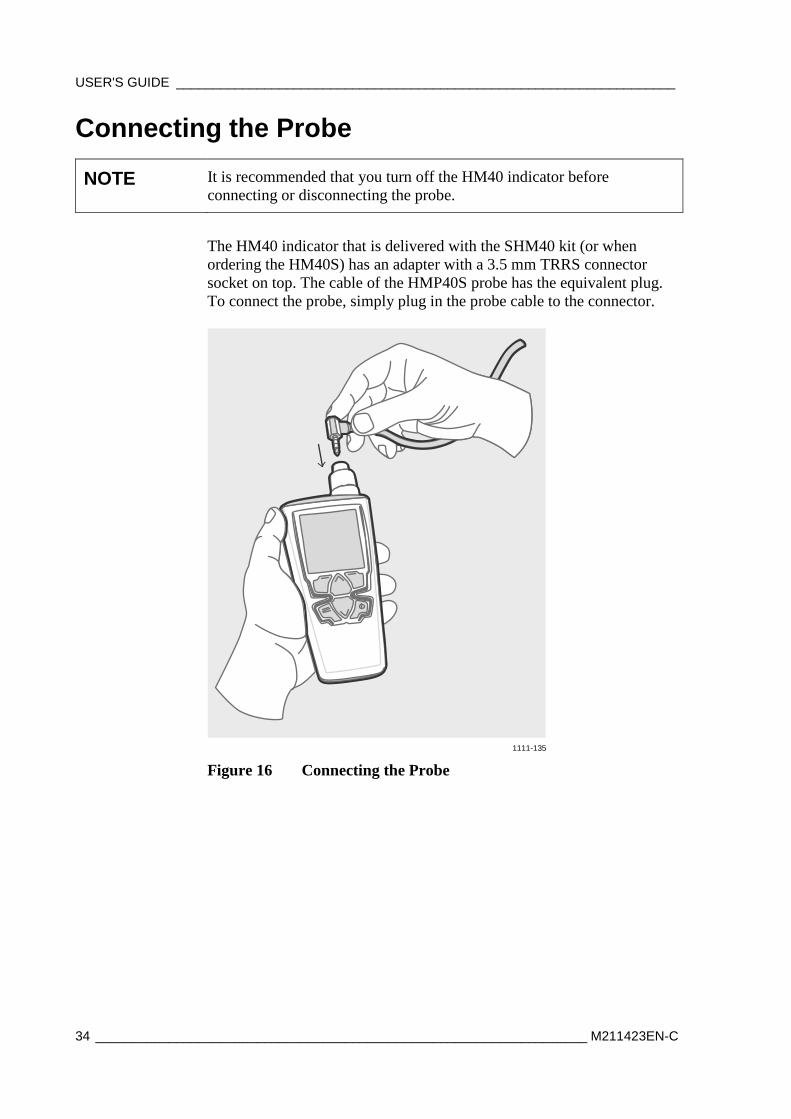
The HM40 indicator that is delivered with the SHM40 kit (or when ordering the HM40S) has an adapter with a 3.5 mm TRRS connector socket on top. The cable of the HMP40S probe has the equivalent plug. To connect the probe, simply plug in the probe cable to the connector.
1111-135
Figure 16 Connecting the Probe
Chapter 4 _____________________________________________________ Using the HM40 Indicator
VAISALA ________________________________________________________________________ 35
First Startup 1. Remove the yellow transport protection cap from the HMP40S
probe, and connect the probe to the HM40 indicator. 2. Open the battery cover and insert two AA-size batteries. 3. Close the battery cover and turn on the HM40 by pressing the
Power button. If the HM40 does not turn on, check the battery orientation. Replace the batteries with fresh/recharged ones if needed.
Initial Settings When you power on the HM40 indicator for the first time (or after a factory reset of the settings), you must first select the operation language. You will then be asked if you want to change the following settings:
- Units - Date - Time
If you answer Yes to the question (recommended), the HM40 will show the settings screens before showing the measurement view. Use the arrow and function buttons to select. For more information, see section Settings Submenu on page 45.
NOTE HM40 indicator will retain the date and time even during battery changes. The clock will have to be set again only if the indicator is without battery power for several hours.
USER'S GUIDE ____________________________________________________________________
36 ___________________________________________________________________ M211423EN-C
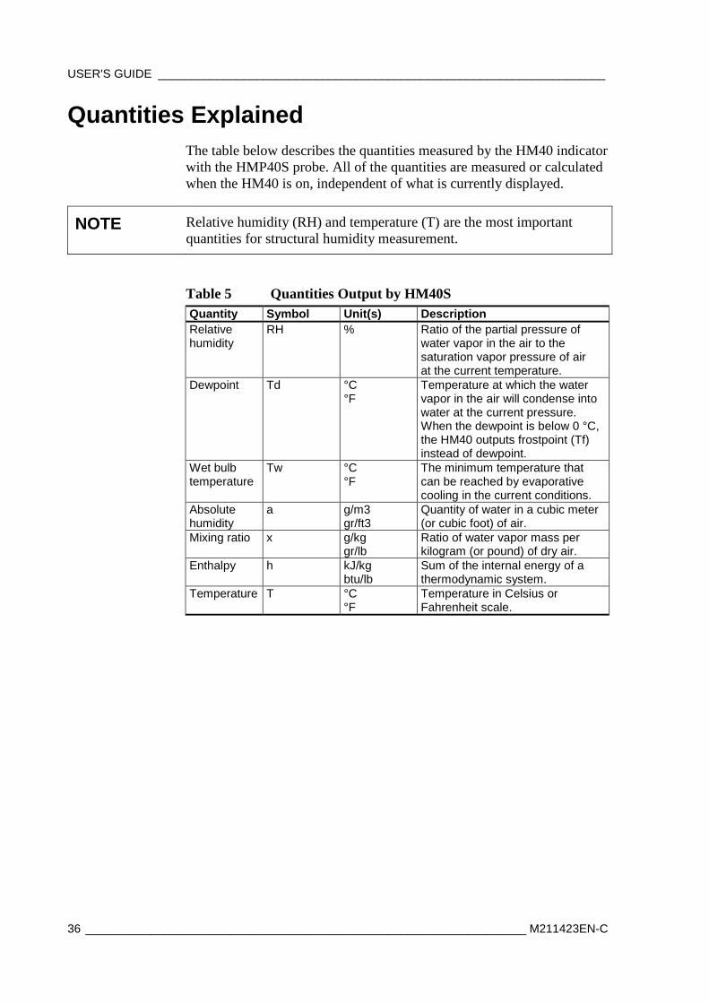
Quantities Explained The table below describes the quantities measured by the HM40 indicator with the HMP40S probe. All of the quantities are measured or calculated when the HM40 is on, independent of what is currently displayed.
NOTE Relative humidity (RH) and temperature (T) are the most important quantities for structural humidity measurement.
Table 5 Quantities Output by HM40S Quantity Symbol Unit(s) Description Relative humidity
RH % Ratio of the partial pressure of water vapor in the air to the saturation vapor pressure of air at the current temperature.
Dewpoint Td °C °F
Temperature at which the water vapor in the air will condense into water at the current pressure. When the dewpoint is below 0 °C, the HM40 outputs frostpoint (Tf) instead of dewpoint.
Wet bulb temperature
Tw °C °F
The minimum temperature that can be reached by evaporative cooling in the current conditions.
Absolute humidity
a g/m3 gr/ft3
Quantity of water in a cubic meter (or cubic foot) of air.
Mixing ratio x g/kg gr/lb
Ratio of water vapor mass per kilogram (or pound) of dry air.
Enthalpy h kJ/kg btu/lb
Sum of the internal energy of a thermodynamic system.
Temperature T °C °F
Temperature in Celsius or Fahrenheit scale.
Chapter 4 _____________________________________________________ Using the HM40 Indicator
VAISALA ________________________________________________________________________ 37
Screen Layout and Controls
1 2
10
8
9
3
5
4
6
7
1112-004
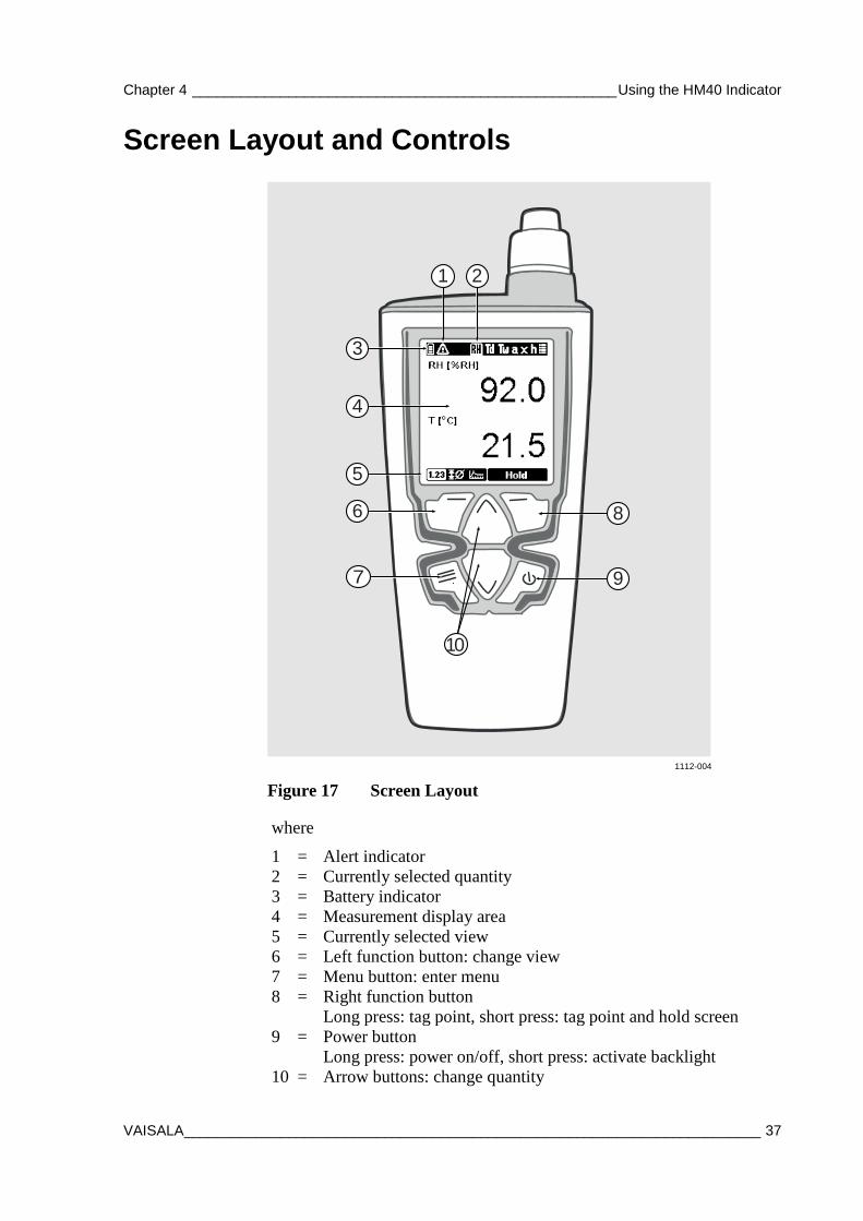
Figure 17 Screen Layout
where
1 = Alert indicator 2 = Currently selected quantity 3 = Battery indicator 4 = Measurement display area 5 = Currently selected view 6 = Left function button: change view 7 = Menu button: enter menu 8 = Right function button
Long press: tag point, short press: tag point and hold screen 9 = Power button
Long press: power on/off, short press: activate backlight 10 = Arrow buttons: change quantity
USER'S GUIDE ____________________________________________________________________
38 ___________________________________________________________________ M211423EN-C
NOTE Pressing the right function button holds the screen and tags the current measurement point. See section Hold and Tag on page 40.
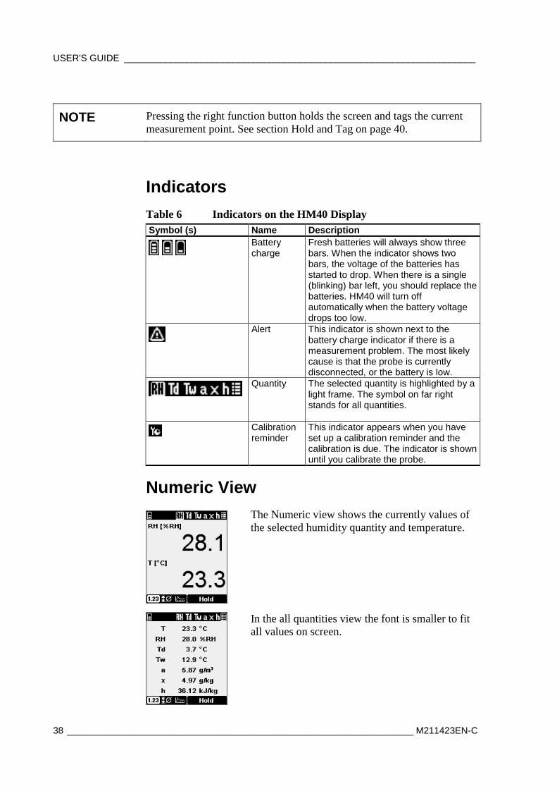
Indicators Table 6 Indicators on the HM40 Display Symbol (s) Name Description
Battery charge
Fresh batteries will always show three bars. When the indicator shows two bars, the voltage of the batteries has started to drop. When there is a single (blinking) bar left, you should replace the batteries. HM40 will turn off automatically when the battery voltage drops too low.
Alert
This indicator is shown next to the battery charge indicator if there is a measurement problem. The most likely cause is that the probe is currently disconnected, or the battery is low.
Quantity
The selected quantity is highlighted by a light frame. The symbol on far right stands for all quantities.
Calibration reminder
This indicator appears when you have set up a calibration reminder and the calibration is due. The indicator is shown until you calibrate the probe.
Numeric View
The Numeric view shows the currently values of the selected humidity quantity and temperature.
In the all quantities view the font is smaller to fit all values on screen.
Chapter 4 _____________________________________________________ Using the HM40 Indicator
VAISALA ________________________________________________________________________ 39
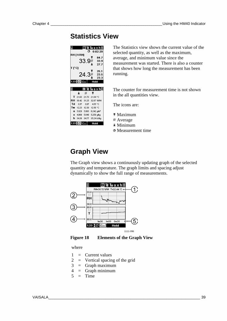
Statistics View
The Statistics view shows the current value of the selected quantity, as well as the maximum, average, and minimum value since the measurement was started. There is also a counter that shows how long the measurement has been running.
The counter for measurement time is not shown in the all quantities view.
The icons are:
Maximum Average Minimum Measurement time
Graph View The Graph view shows a continuously updating graph of the selected quantity and temperature. The graph limits and spacing adjust dynamically to show the full range of measurements.
1111-096
Figure 18 Elements of the Graph View
where
1 = Current values 2 = Vertical spacing of the grid 3 = Graph maximum 4 = Graph minimum 5 = Time
USER'S GUIDE ____________________________________________________________________
40 ___________________________________________________________________ M211423EN-C
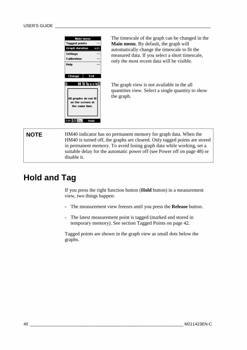
The timescale of the graph can be changed in the Main menu. By default, the graph will automatically change the timescale to fit the measured data. If you select a short timescale, only the most recent data will be visible.
The graph view is not available in the all quantities view. Select a single quantity to show the graph.
NOTE HM40 indicator has no permanent memory for graph data. When the HM40 is turned off, the graphs are cleared. Only tagged points are stored in permanent memory. To avoid losing graph data while working, set a suitable delay for the automatic power off (see Power off on page 48) or disable it.
Hold and Tag If you press the right function button (Hold button) in a measurement view, two things happen:
- The measurement view freezes until you press the Release button.
- The latest measurement point is tagged (marked and stored in temporary memory). See section Tagged Points on page 42.
Tagged points are shown in the graph view as small dots below the graphs.
Chapter 4 _____________________________________________________ Using the HM40 Indicator
VAISALA ________________________________________________________________________ 41
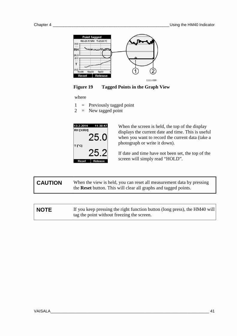
1111-099
Figure 19 Tagged Points in the Graph View
where
1 = Previously tagged point 2 = New tagged point
When the screen is held, the top of the display displays the current date and time. This is useful when you want to record the current data (take a photograph or write it down).
If date and time have not been set, the top of the screen will simply read “HOLD”.
CAUTION When the view is held, you can reset all measurement data by pressing the Reset button. This will clear all graphs and tagged points.
NOTE If you keep pressing the right function button (long press), the HM40 will tag the point without freezing the screen.
USER'S GUIDE ____________________________________________________________________
42 ___________________________________________________________________ M211423EN-C
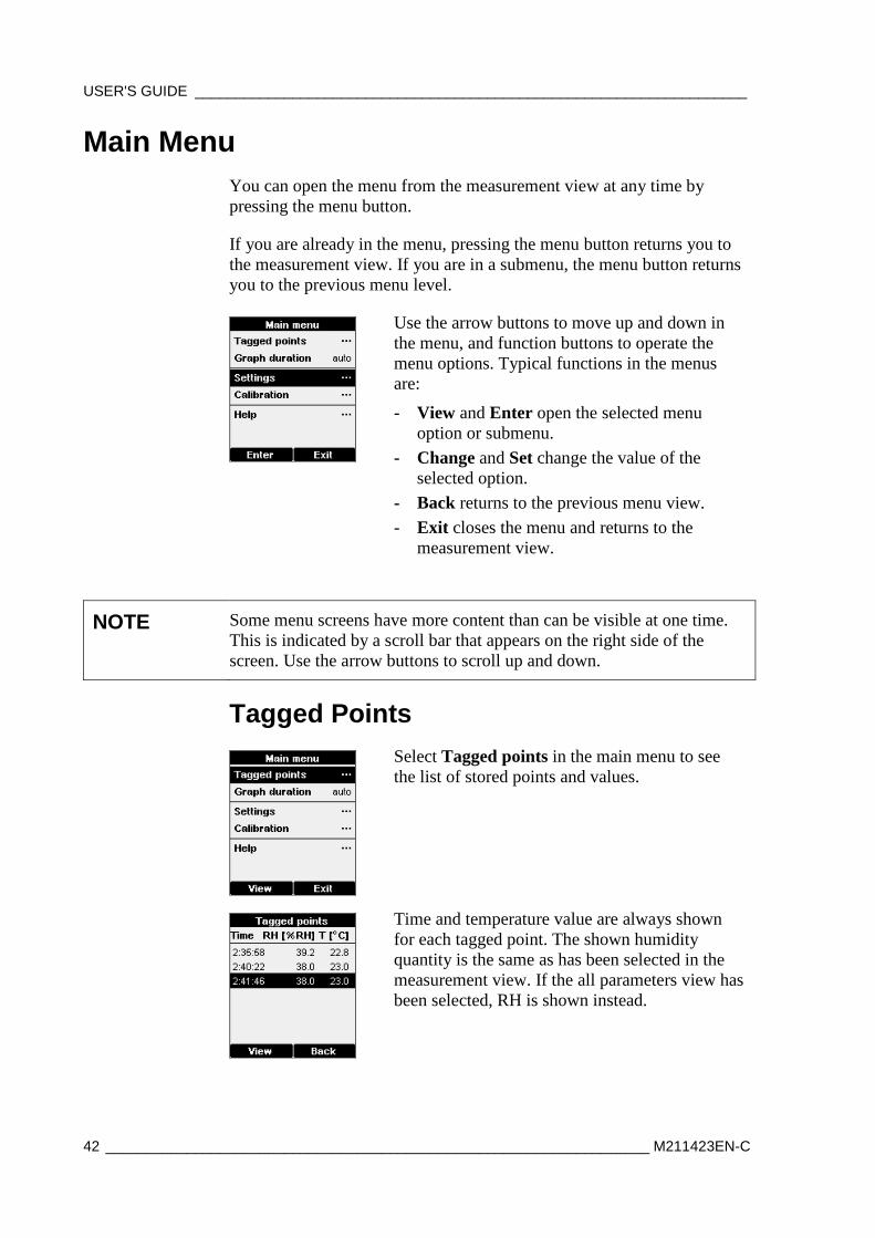
Main Menu You can open the menu from the measurement view at any time by pressing the menu button.
If you are already in the menu, pressing the menu button returns you to the measurement view. If you are in a submenu, the menu button returns you to the previous menu level.
Use the arrow buttons to move up and down in the menu, and function buttons to operate the menu options. Typical functions in the menus are:
- View and Enter open the selected menu option or submenu.
- Change and Set change the value of the selected option.
- Back returns to the previous menu view. - Exit closes the menu and returns to the
measurement view.
NOTE Some menu screens have more content than can be visible at one time. This is indicated by a scroll bar that appears on the right side of the screen. Use the arrow buttons to scroll up and down.
Tagged Points
Select Tagged points in the main menu to see the list of stored points and values.
Time and temperature value are always shown for each tagged point. The shown humidity quantity is the same as has been selected in the measurement view. If the all parameters view has been selected, RH is shown instead.
Chapter 4 _____________________________________________________ Using the HM40 Indicator
VAISALA ________________________________________________________________________ 43
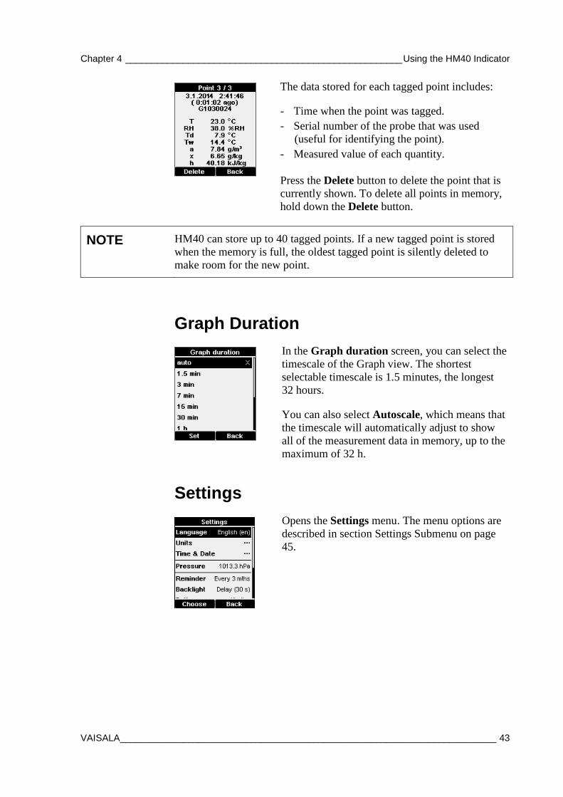
The data stored for each tagged point includes:
- Time when the point was tagged. - Serial number of the probe that was used
(useful for identifying the point). - Measured value of each quantity.
Press the Delete button to delete the point that is currently shown. To delete all points in memory, hold down the Delete button.
NOTE HM40 can store up to 40 tagged points. If a new tagged point is stored when the memory is full, the oldest tagged point is silently deleted to make room for the new point.
Graph Duration
In the Graph duration screen, you can select the timescale of the Graph view. The shortest selectable timescale is 1.5 minutes, the longest 32 hours.
You can also select Autoscale, which means that the timescale will automatically adjust to show all of the measurement data in memory, up to the maximum of 32 h.
Settings
Opens the Settings menu. The menu options are described in section Settings Submenu on page 45.
USER'S GUIDE ____________________________________________________________________
44 ___________________________________________________________________ M211423EN-C
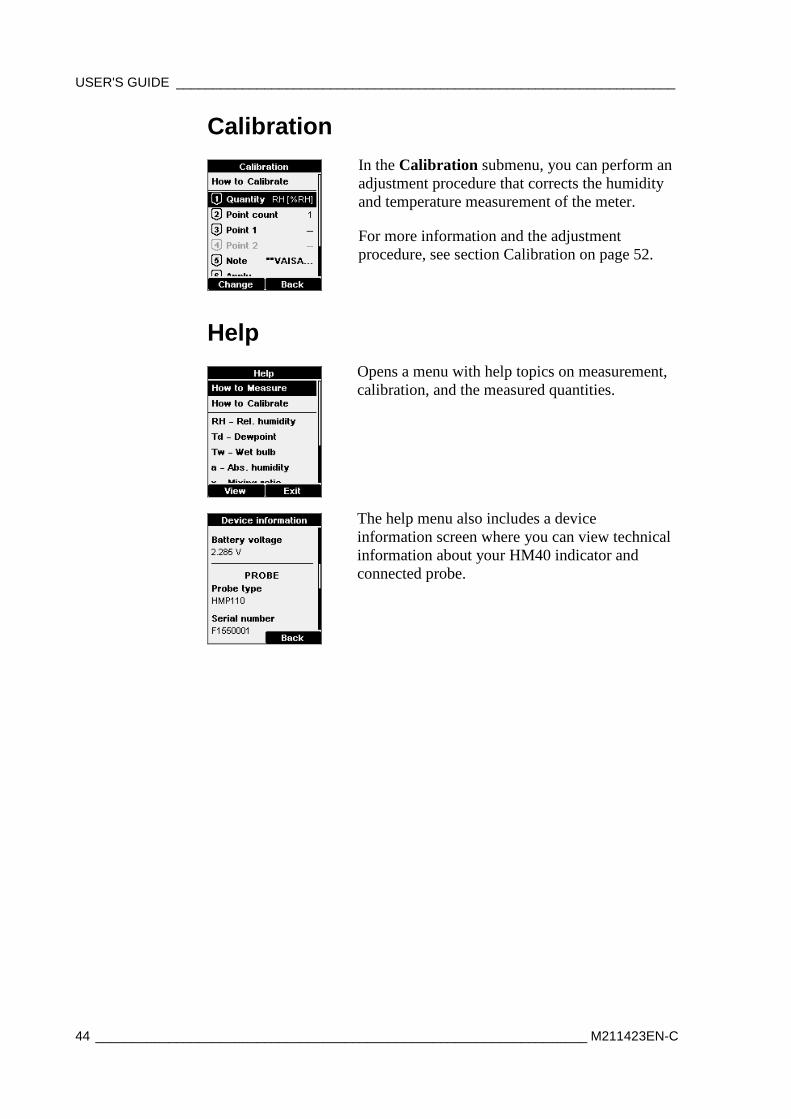
Calibration
In the Calibration submenu, you can perform an adjustment procedure that corrects the humidity and temperature measurement of the meter.
For more information and the adjustment procedure, see section Calibration on page 52.
Help
Opens a menu with help topics on measurement, calibration, and the measured quantities.
The help menu also includes a device information screen where you can view technical information about your HM40 indicator and connected probe.
Chapter 4 _____________________________________________________ Using the HM40 Indicator
VAISALA ________________________________________________________________________ 45
Settings Submenu
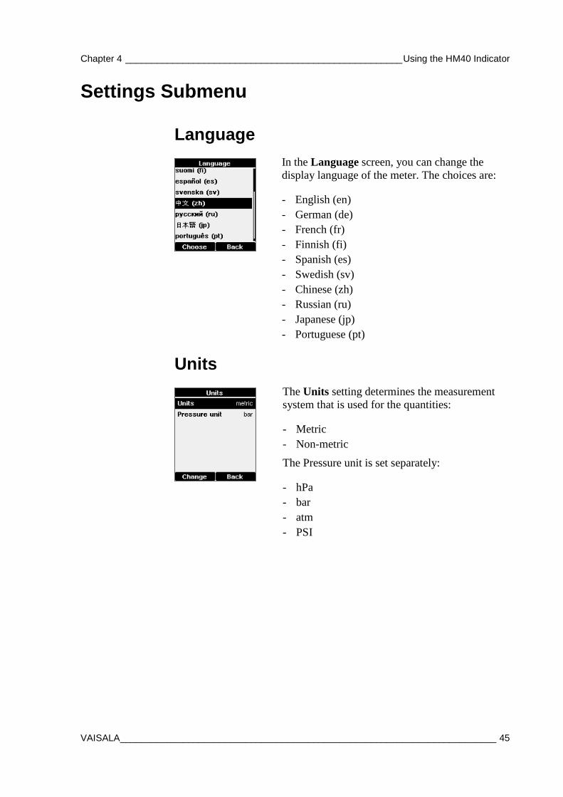
Language
In the Language screen, you can change the display language of the meter. The choices are:
- English (en) - German (de) - French (fr) - Finnish (fi) - Spanish (es) - Swedish (sv) - Chinese (zh) - Russian (ru) - Japanese (jp) - Portuguese (pt)
Units
The Units setting determines the measurement system that is used for the quantities:
- Metric - Non-metric
The Pressure unit is set separately:
- hPa - bar - atm - PSI
USER'S GUIDE ____________________________________________________________________
46 ___________________________________________________________________ M211423EN-C
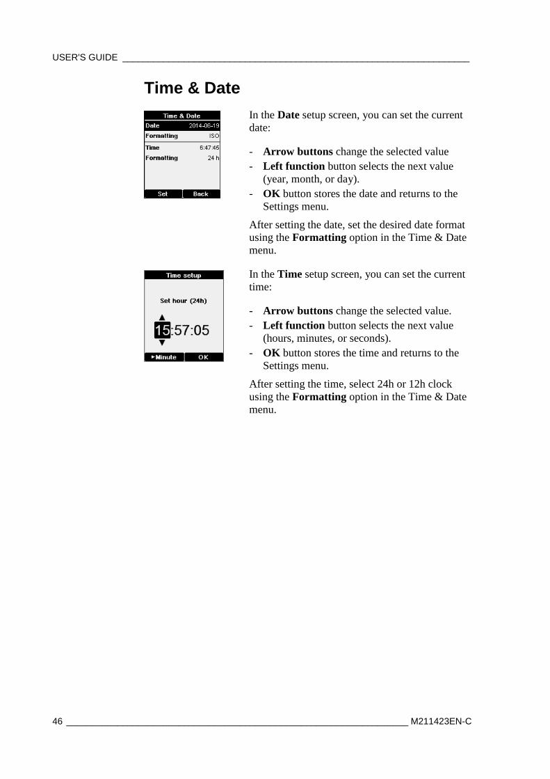
Time & Date
In the Date setup screen, you can set the current date:
- Arrow buttons change the selected value - Left function button selects the next value
(year, month, or day). - OK button stores the date and returns to the
Settings menu.
After setting the date, set the desired date format using the Formatting option in the Time & Date menu.
In the Time setup screen, you can set the current time:
- Arrow buttons change the selected value. - Left function button selects the next value
(hours, minutes, or seconds). - OK button stores the time and returns to the
Settings menu.
After setting the time, select 24h or 12h clock using the Formatting option in the Time & Date menu.
Chapter 4 _____________________________________________________ Using the HM40 Indicator
VAISALA ________________________________________________________________________ 47
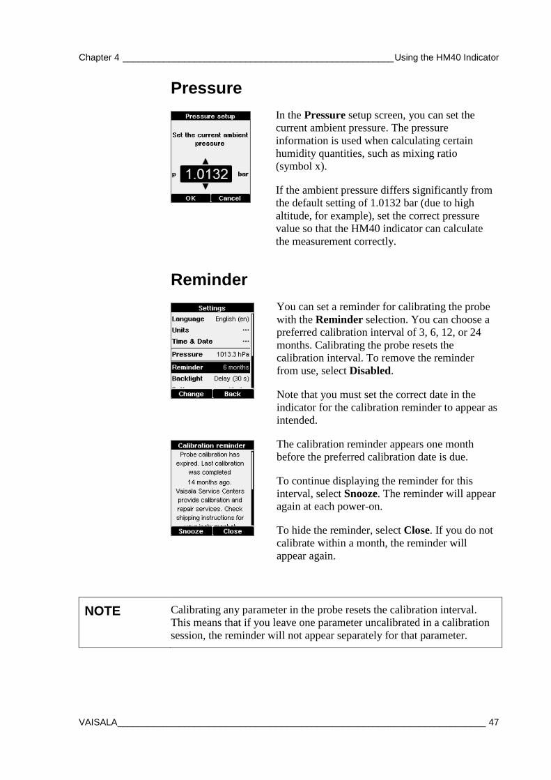
Pressure
In the Pressure setup screen, you can set the current ambient pressure. The pressure information is used when calculating certain humidity quantities, such as mixing ratio (symbol x).
If the ambient pressure differs significantly from the default setting of 1.0132 bar (due to high altitude, for example), set the correct pressure value so that the HM40 indicator can calculate the measurement correctly.
Reminder
You can set a reminder for calibrating the probe with the Reminder selection. You can choose a preferred calibration interval of 3, 6, 12, or 24 months. Calibrating the probe resets the calibration interval. To remove the reminder from use, select Disabled.
Note that you must set the correct date in the indicator for the calibration reminder to appear as intended.
The calibration reminder appears one month before the preferred calibration date is due.
To continue displaying the reminder for this interval, select Snooze. The reminder will appear again at each power-on.
To hide the reminder, select Close. If you do not calibrate within a month, the reminder will appear again.
NOTE Calibrating any parameter in the probe resets the calibration interval. This means that if you leave one parameter uncalibrated in a calibration session, the reminder will not appear separately for that parameter.
USER'S GUIDE ____________________________________________________________________
48 ___________________________________________________________________ M211423EN-C
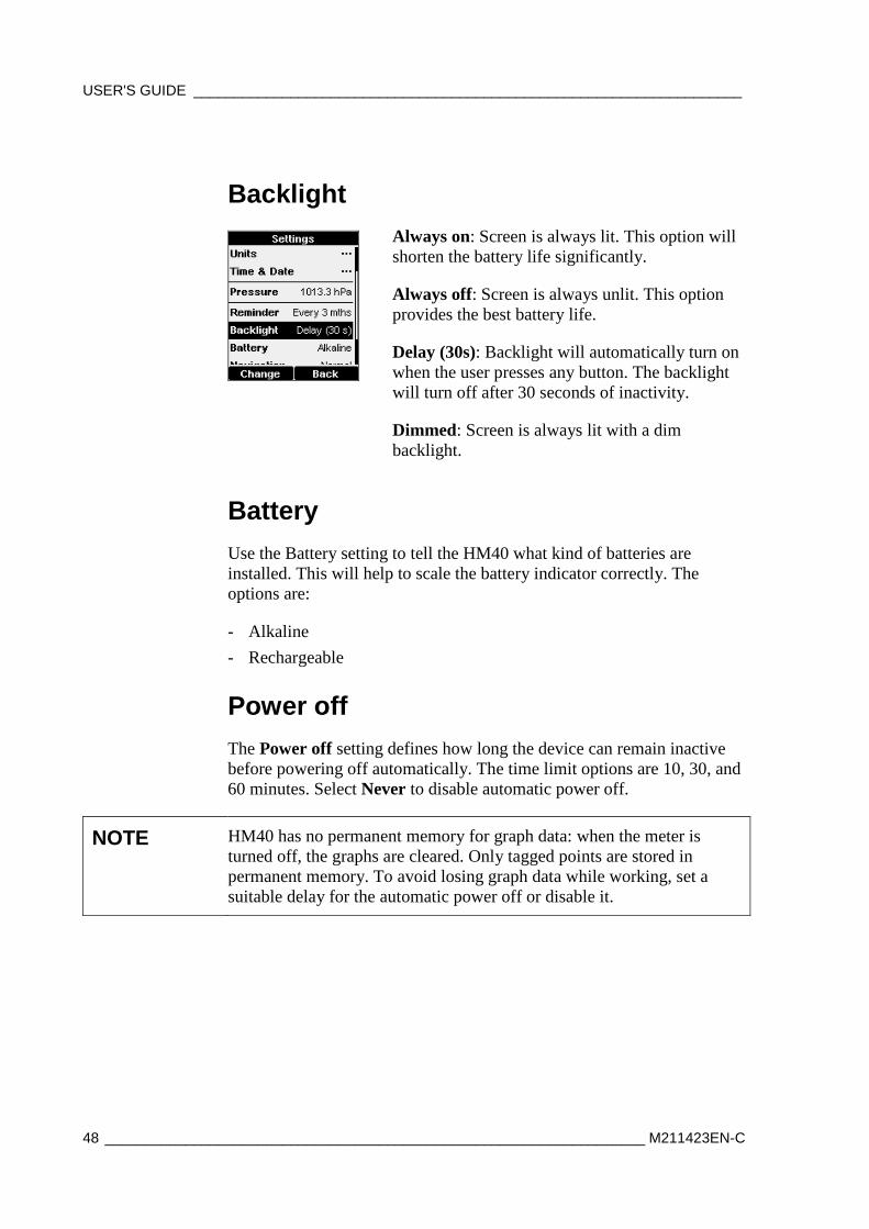
Backlight
Always on: Screen is always lit. This option will shorten the battery life significantly.
Always off: Screen is always unlit. This option provides the best battery life.
Delay (30s): Backlight will automatically turn on when the user presses any button. The backlight will turn off after 30 seconds of inactivity.
Dimmed: Screen is always lit with a dim backlight.
Battery Use the Battery setting to tell the HM40 what kind of batteries are installed. This will help to scale the battery indicator correctly. The options are:
- Alkaline - Rechargeable
Power off The Power off setting defines how long the device can remain inactive before powering off automatically. The time limit options are 10, 30, and 60 minutes. Select Never to disable automatic power off.
NOTE HM40 has no permanent memory for graph data: when the meter is turned off, the graphs are cleared. Only tagged points are stored in permanent memory. To avoid losing graph data while working, set a suitable delay for the automatic power off or disable it.
Chapter 4 _____________________________________________________ Using the HM40 Indicator
VAISALA ________________________________________________________________________ 49
Navigation The Navigation setting affects the behavior of arrow buttons in the measurement view:
- Normal: Up arrow moves quantity selector left, down arrow moves it right
- Inverted: Reverses the direction
Rounding The Rounding setting affects the number of decimal places that are used to show the measurements:
- On: Measured values are rounded to one decimal place. - Off: Measured values are shown with two decimal places.
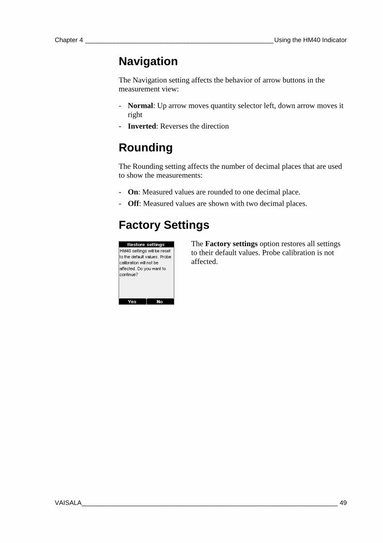
Factory Settings
The Factory settings option restores all settings to their default values. Probe calibration is not affected.

USER'S GUIDE ____________________________________________________________________
50 ___________________________________________________________________ M211423EN-C
This page intentionally left blank.
Chapter 5 _______________________________________________________________ Maintenance
VAISALA ________________________________________________________________________ 51
CHAPTER 5
MAINTENANCE
This chapter provides information that is needed in basic maintenance of the SHM40 kit.
Periodic Maintenance
Cleaning HM40 indicator can be cleaned by wiping it with a moist cloth.
If the filter on the HMP40S probe becomes contaminated, it is very likely to affect the humidity measurement since residue on the filter will retain some moisture. Dirty filters must be replaced.
Do not use solvents to clean the HM40 indicator or the HMP40S probe. Do not spray anything directly on the HMP40S, since that may deposit impurities on the sensor.
CAUTION Do not immerse the HM40 indicator or the HMP40S probe in liquid.
CAUTION Do not attempt to clean the sensor element that is located inside the filter. Any touching (or blowing with pressurized air) may damage it. If the measurement accuracy cannot be restored by calibration and adjustment, it is time to replace the HMP40S probe.
USER'S GUIDE ____________________________________________________________________
52 ___________________________________________________________________ M211423EN-C
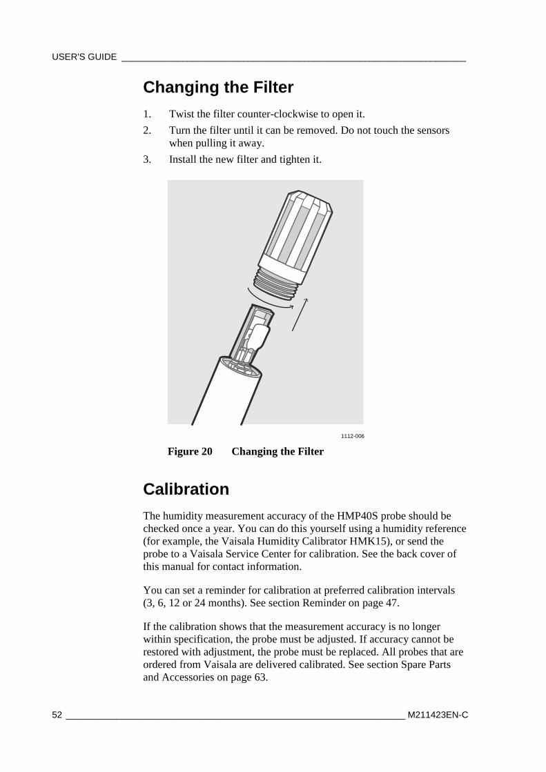
Changing the Filter 1. Twist the filter counter-clockwise to open it. 2. Turn the filter until it can be removed. Do not touch the sensors
when pulling it away. 3. Install the new filter and tighten it.
1112-006
Figure 20 Changing the Filter
Calibration The humidity measurement accuracy of the HMP40S probe should be checked once a year. You can do this yourself using a humidity reference (for example, the Vaisala Humidity Calibrator HMK15), or send the probe to a Vaisala Service Center for calibration. See the back cover of this manual for contact information.
You can set a reminder for calibration at preferred calibration intervals (3, 6, 12 or 24 months). See section Reminder on page 47.
If the calibration shows that the measurement accuracy is no longer within specification, the probe must be adjusted. If accuracy cannot be restored with adjustment, the probe must be replaced. All probes that are ordered from Vaisala are delivered calibrated. See section Spare Parts and Accessories on page 63.
Chapter 5 _______________________________________________________________ Maintenance
VAISALA ________________________________________________________________________ 53
CAUTION If you think the HM40 is not measuring humidity or temperature correctly, calibration and adjustment is not the first thing to do. Try the following first:
- Make sure nothing is interfering with the measurement: heat sources, temperature differences, or condensation.
- Check that there is no moisture on the probe. If the sensor has become wet, you must allow it to dry before you can measure.
- Always wait for the measurement to stabilize.
NOTE For an introduction to calibration, order or download the free calibration book from Vaisala at the following address: www.vaisala.com/calibrationbook
Calibrating the HMP40S Probe Using HMK15 Humidity Calibrator The HMK15 Humidity calibrator allows you to produce known humidity environments using saturated salt solutions.
NOTE Performing a good calibration takes some time and preparation. Read the HMK15 User’s Guide before performing your first calibration with the HMK15.
NOTE In 2-point calibration, the first point requires a < 50 %RH humidity reference, and the second point must be > 50 %RH. There must also be at least a 30 percentage point difference between the references.
USER'S GUIDE ____________________________________________________________________
54 ___________________________________________________________________ M211423EN-C
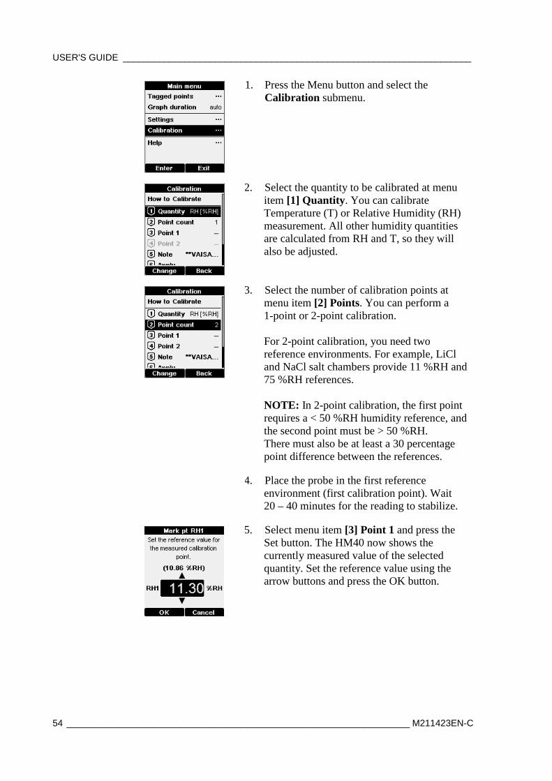
1. Press the Menu button and select the Calibration submenu.
2. Select the quantity to be calibrated at menu item [1] Quantity. You can calibrate Temperature (T) or Relative Humidity (RH) measurement. All other humidity quantities are calculated from RH and T, so they will also be adjusted.
3. Select the number of calibration points at menu item [2] Points. You can perform a 1-point or 2-point calibration. For 2-point calibration, you need two reference environments. For example, LiCl and NaCl salt chambers provide 11 %RH and 75 %RH references. NOTE: In 2-point calibration, the first point requires a < 50 %RH humidity reference, and the second point must be > 50 %RH. There must also be at least a 30 percentage point difference between the references.
4. Place the probe in the first reference environment (first calibration point). Wait 20 – 40 minutes for the reading to stabilize.
5. Select menu item [3] Point 1 and press the Set button. The HM40 now shows the currently measured value of the selected quantity. Set the reference value using the arrow buttons and press the OK button.
Chapter 5 _______________________________________________________________ Maintenance
VAISALA ________________________________________________________________________ 55
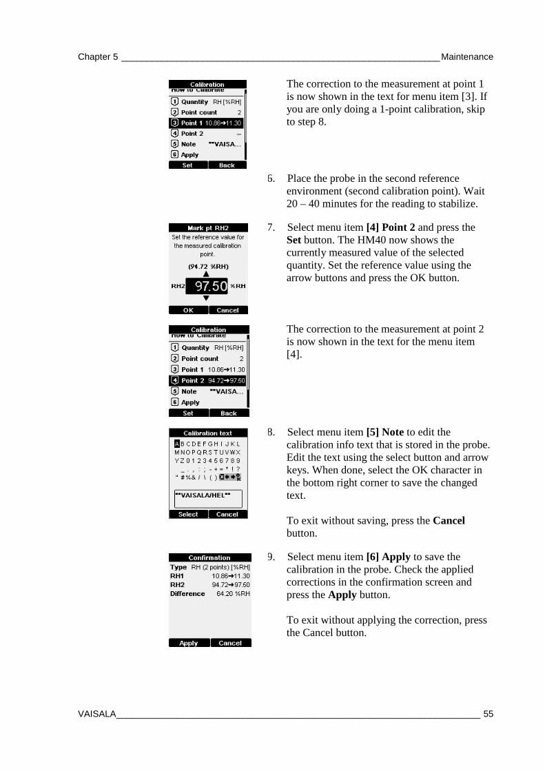
The correction to the measurement at point 1 is now shown in the text for menu item [3]. If you are only doing a 1-point calibration, skip to step 8.
6. Place the probe in the second reference environment (second calibration point). Wait 20 – 40 minutes for the reading to stabilize.
7. Select menu item [4] Point 2 and press the Set button. The HM40 now shows the currently measured value of the selected quantity. Set the reference value using the arrow buttons and press the OK button.
The correction to the measurement at point 2 is now shown in the text for the menu item [4].
8. Select menu item [5] Note to edit the calibration info text that is stored in the probe. Edit the text using the select button and arrow keys. When done, select the OK character in the bottom right corner to save the changed text. To exit without saving, press the Cancel button.
9. Select menu item [6] Apply to save the calibration in the probe. Check the applied corrections in the confirmation screen and press the Apply button. To exit without applying the correction, press the Cancel button.
USER'S GUIDE ____________________________________________________________________
56 ___________________________________________________________________ M211423EN-C
Repair Maintenance There are no user serviceable parts inside the housing of the HM40 indicator or the HMP40S probe. Depending on the malfunction, repair by a Vaisala Service Center may be possible.
Replacement HM40 indicators, HMP40S probes, and measurement accessories are available from Vaisala. See section Spare Parts and Accessories on page 63.
Chapter 6 ____________________________________________________________ Troubleshooting
VAISALA ________________________________________________________________________ 57
CHAPTER 6
TROUBLESHOOTING
This chapter describes common problems, their probable causes and remedies, and provides contact information for technical support.
Avoid Condensation and Rain If the humidity sensor element on the probe becomes wet, the probe cannot measure until the sensor is dry again. Avoid rain and conditions where condensation can form on the sensor.
Do not use the transport protection cap if the probe is wet, since it will prevent the probe from drying.
CAUTION Do not touch the sensor or blow on it to dry it out.
USER'S GUIDE ____________________________________________________________________
58 ___________________________________________________________________ M211423EN-C
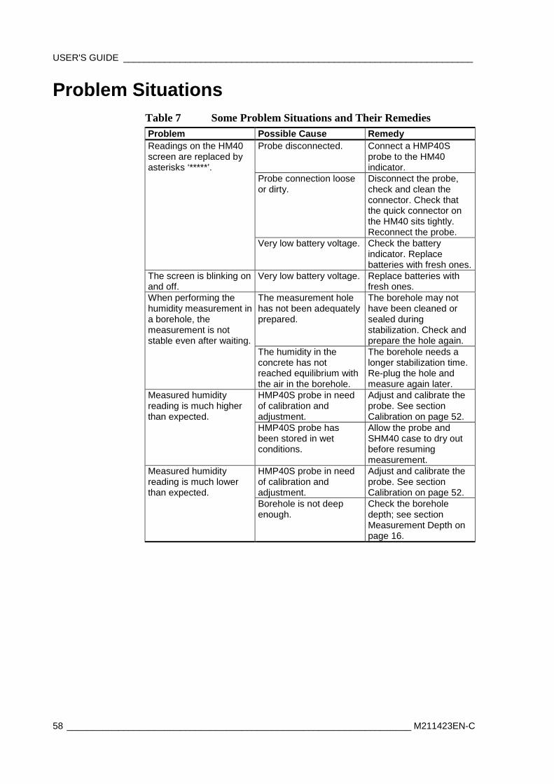
Problem Situations Table 7 Some Problem Situations and Their Remedies Problem Possible Cause Remedy Readings on the HM40 screen are replaced by asterisks ‘*****’.
Probe disconnected.
Connect a HMP40S probe to the HM40 indicator.
Probe connection loose or dirty.
Disconnect the probe, check and clean the connector. Check that the quick connector on the HM40 sits tightly. Reconnect the probe.
Very low battery voltage. Check the battery indicator. Replace batteries with fresh ones.
The screen is blinking on and off.
Very low battery voltage. Replace batteries with fresh ones.
When performing the humidity measurement in a borehole, the measurement is not stable even after waiting.
The measurement hole has not been adequately prepared.
The borehole may not have been cleaned or sealed during stabilization. Check and prepare the hole again.
The humidity in the concrete has not reached equilibrium with the air in the borehole.
The borehole needs a longer stabilization time. Re-plug the hole and measure again later.
Measured humidity reading is much higher than expected.
HMP40S probe in need of calibration and adjustment.
Adjust and calibrate the probe. See section Calibration on page 52.
HMP40S probe has been stored in wet conditions.
Allow the probe and SHM40 case to dry out before resuming measurement.
Measured humidity reading is much lower than expected.
HMP40S probe in need of calibration and adjustment.
Adjust and calibrate the probe. See section Calibration on page 52.
Borehole is not deep enough.
Check the borehole depth; see section Measurement Depth on page 16.

Chapter 6 ____________________________________________________________ Troubleshooting
VAISALA ________________________________________________________________________ 59
Technical Support For technical questions, contact the Vaisala technical support by e-mail at [email protected]. Provide at least the following supporting information:
- Name and model of the product in question - Serial number of the product - Name and location of the installation site - Name and contact information of a technically competent person who
can provide further information on the problem. For contact information of Vaisala Service Centers, see www.vaisala.com/servicecenters.

USER'S GUIDE ____________________________________________________________________
60 ___________________________________________________________________ M211423EN-C
This page intentionally left blank.
Chapter 7 _____________________________________________________________ Technical Data
VAISALA ________________________________________________________________________ 61
CHAPTER 7
TECHNICAL DATA
This chapter provides the technical data of the SHM40 kit.
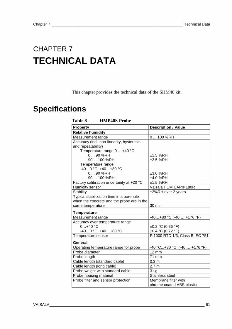
Specifications Table 8 HMP40S Probe Property Description / Value Relative humidity Measurement range 0 ... 100 %RH Accuracy (incl. non-linearity, hysteresis and repeatability)
Temperature range 0 ... +40 °C 0 ... 90 %RH ±1.5 %RH 90 ... 100 %RH ±2.5 %RH Temperature range
-40…0 °C, +40…+80 °C
0 ... 90 %RH ±3.0 %RH 90 ... 100 %RH ±4.0 %RH Factory calibration uncertainty at +20 °C ±1.5 %RH Humidity sensor Vaisala HUMICAP® 180R Stability ±2%RH over 2 years Typical stabilization time in a borehole when the concrete and the probe are in the same temperature 30 min
Temperature
Measurement range -40…+80 °C (-40 … +176 °F) Accuracy over temperature range 0…+40 °C ±0.2 °C (0.36 °F) -40…0 °C, +40…+80 °C ±0.4 °C (0.72 °F) Temperature sensor Pt1000 RTD 1/3, Class B IEC 751
General
Operating temperature range for probe -40 °C...+80 °C (-40 … +176 °F) Probe diameter 12 mm Probe length 71 mm Cable length (standard cable) 0.3 m Cable length (long cable) 2.7 m Probe weight with standard cable 31 g Probe housing material Stainless steel Probe filter and sensor protection Membrane filter with
chrome coated ABS plastic
USER'S GUIDE ____________________________________________________________________
62 ___________________________________________________________________ M211423EN-C
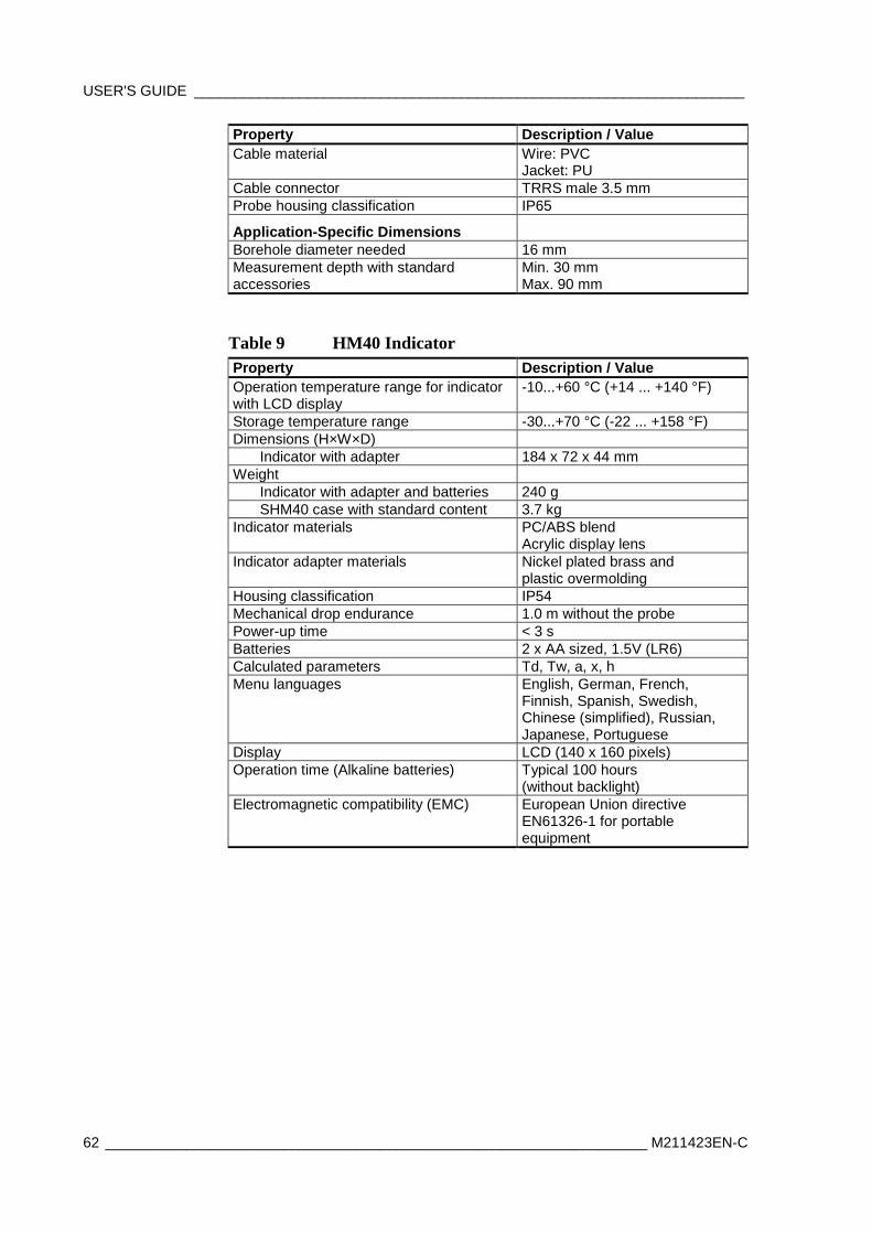
Property Description / Value Cable material Wire: PVC
Jacket: PU Cable connector TRRS male 3.5 mm Probe housing classification IP65
Application-Specific Dimensions
Borehole diameter needed 16 mm Measurement depth with standard accessories
Min. 30 mm Max. 90 mm
Table 9 HM40 Indicator Property Description / Value Operation temperature range for indicator with LCD display
-10...+60 °C (+14 ... +140 °F)
Storage temperature range -30...+70 °C (-22 ... +158 °F) Dimensions (H×W×D) Indicator with adapter 184 x 72 x 44 mm Weight Indicator with adapter and batteries 240 g SHM40 case with standard content 3.7 kg Indicator materials PC/ABS blend
Acrylic display lens Indicator adapter materials Nickel plated brass and
plastic overmolding Housing classification IP54 Mechanical drop endurance 1.0 m without the probe Power-up time < 3 s Batteries 2 x AA sized, 1.5V (LR6) Calculated parameters Td, Tw, a, x, h Menu languages English, German, French,
Finnish, Spanish, Swedish, Chinese (simplified), Russian, Japanese, Portuguese
Display LCD (140 x 160 pixels) Operation time (Alkaline batteries) Typical 100 hours
(without backlight) Electromagnetic compatibility (EMC) European Union directive
EN61326-1 for portable equipment
Chapter 7 _____________________________________________________________ Technical Data
VAISALA ________________________________________________________________________ 63
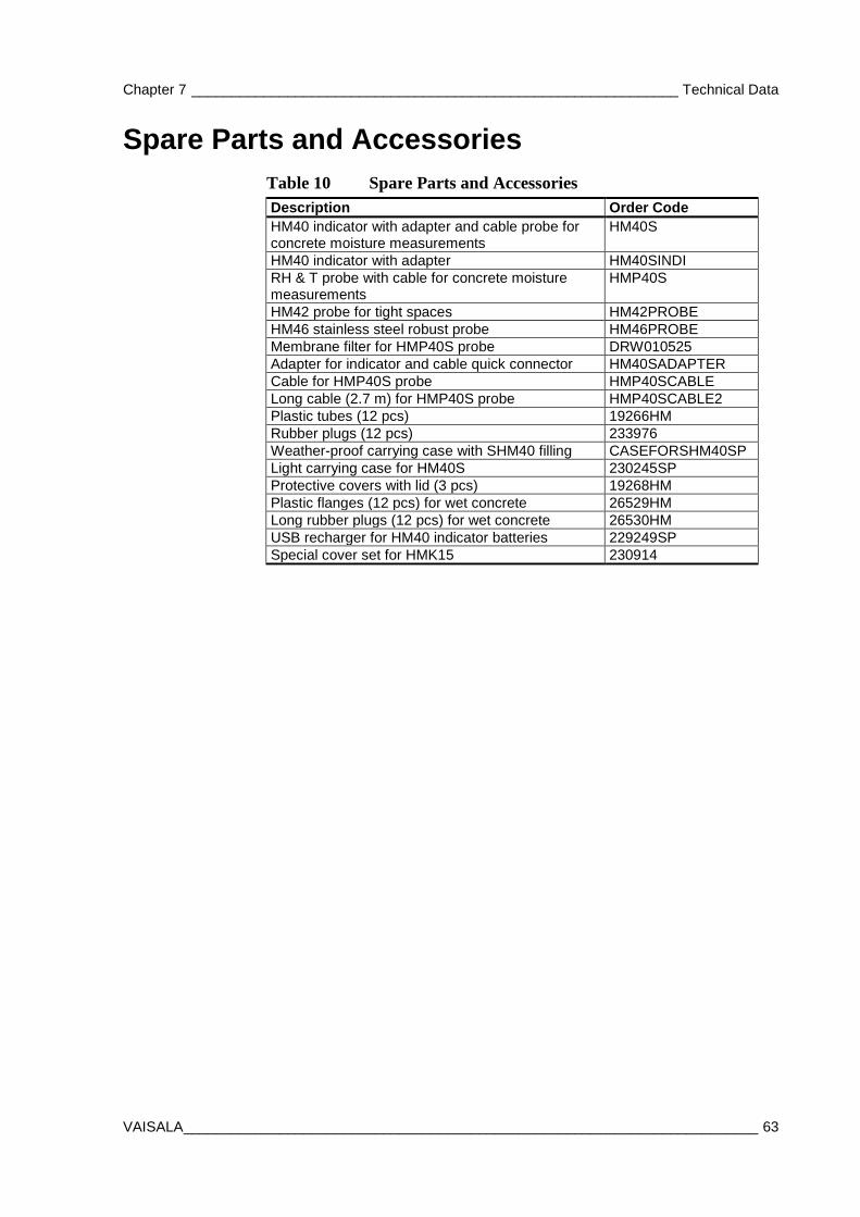
Spare Parts and Accessories Table 10 Spare Parts and Accessories Description Order Code HM40 indicator with adapter and cable probe for concrete moisture measurements
HM40S
HM40 indicator with adapter HM40SINDI RH & T probe with cable for concrete moisture measurements
HMP40S
HM42 probe for tight spaces HM42PROBE HM46 stainless steel robust probe HM46PROBE Membrane filter for HMP40S probe DRW010525 Adapter for indicator and cable quick connector HM40SADAPTER Cable for HMP40S probe HMP40SCABLE Long cable (2.7 m) for HMP40S probe HMP40SCABLE2 Plastic tubes (12 pcs) 19266HM Rubber plugs (12 pcs) 233976 Weather-proof carrying case with SHM40 filling CASEFORSHM40SP Light carrying case for HM40S 230245SP Protective covers with lid (3 pcs) 19268HM Plastic flanges (12 pcs) for wet concrete 26529HM Long rubber plugs (12 pcs) for wet concrete 26530HM USB recharger for HM40 indicator batteries 229249SP Special cover set for HMK15 230914
USER'S GUIDE ____________________________________________________________________
64 ___________________________________________________________________ M211423EN-C
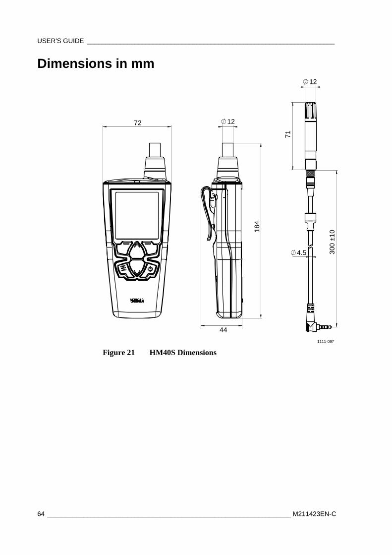
Dimensions in mm
72
184
300
±10
71
12
44
12
4.5
1111-097
Figure 21 HM40S Dimensions

Appendix A ______________________________________________________ Humidity Report Form
VAISALA ________________________________________________________________________ 65
APPENDIX A
HUMIDITY REPORT FORM
This appendix contains an example report form that can be used to record humidity measurement results in concrete.
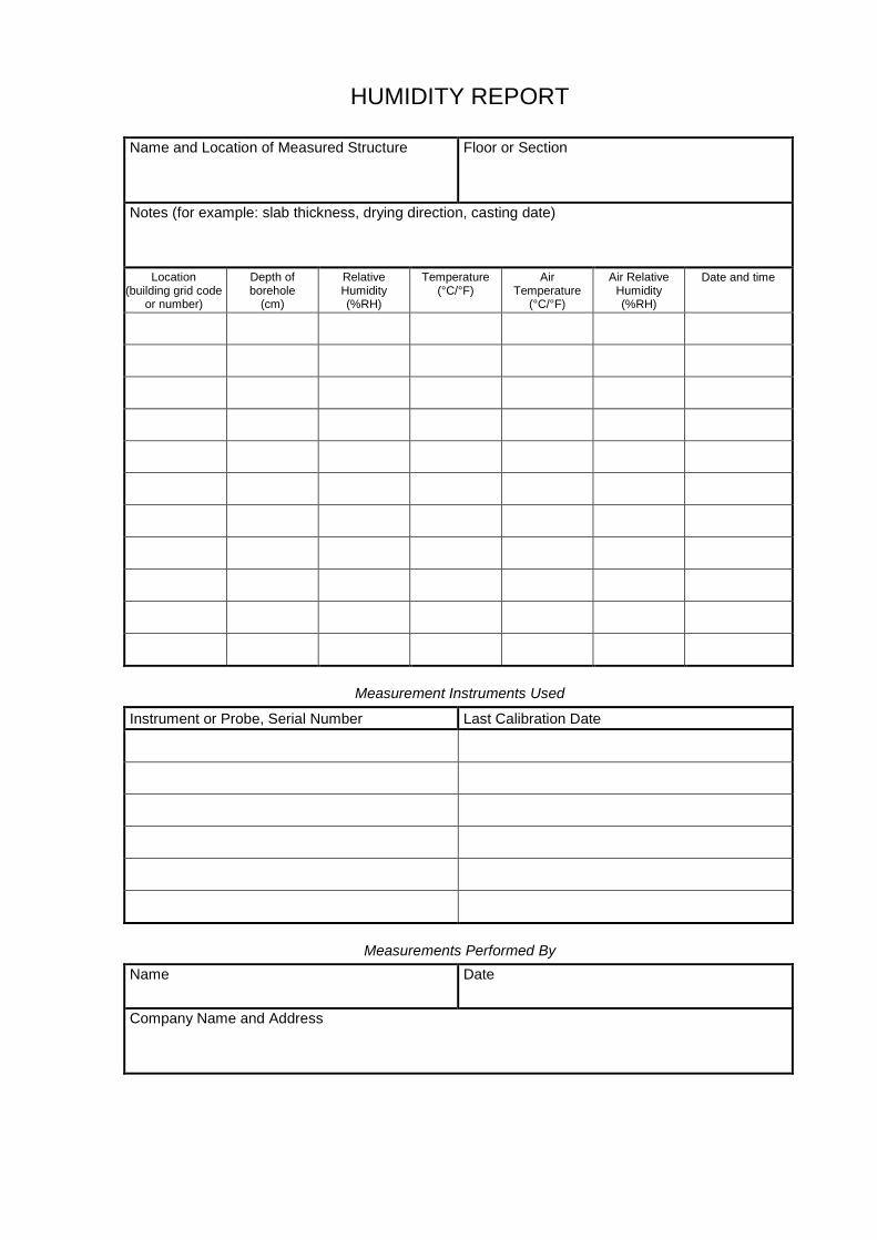
HUMIDITY REPORT
Name and Location of Measured Structure Floor or Section
Notes (for example: slab thickness, drying direction, casting date)
Location (building grid code
or number)
Depth of borehole
(cm)
Relative Humidity (%RH)
Temperature (°C/°F)
Air Temperature
(°C/°F)
Air Relative Humidity (%RH)
Date and time
Measurement Instruments Used
Instrument or Probe, Serial Number Last Calibration Date
Measurements Performed By Name Date
Company Name and Address


www.vaisala.com
*M211423EN*