Embed Size (px)
Citation preview

vacon nxac drives
optci modbus/tcp option board
user manual
2 • vacon Introduction
Tel. +358 (0)201 2121 • Fax +358 (0)201 212 205
INDEX
Document code: DPD00900A Last edited: 26.1.2012
1. Introduction ....................................................................................................................... 3
2. Ethernet board technical data ............................................................................................ 4
2.1 Overview .................................................................................................................................... 4 2.2 LED indications ......................................................................................................................... 4 2.3 Ethernet .................................................................................................................................... 5 2.4 Connections and Wiring ............................................................................................................ 6
3. Installation ......................................................................................................................... 7
3.1 Installing the Ethernet Option Board in a Vacon NX Unit ......................................................... 7 3.2 NCDrive ..................................................................................................................................... 9 3.3 IP Tool NCIPConfig .................................................................................................................... 9
4. Commissioning ................................................................................................................ 13
5. MODBUS/TCP ................................................................................................................... 15
5.1 Overview .................................................................................................................................. 15 5.2 MODBUS/TCP vs. MODBUS RTU ............................................................................................. 16 5.3 Ethernet Option Board's Modbus Addresses .......................................................................... 16 5.4 Supported Modbus Functions ................................................................................................. 16 5.5 Coil Register ............................................................................................................................ 16 5.6 Input Discrete .......................................................................................................................... 18 5.7 Holding Registers .................................................................................................................... 20 5.8 Input Registers ........................................................................................................................ 24
6. Start-up Test .................................................................................................................... 27
6.1 Frequency Converter Settings ................................................................................................ 27 6.2 Master Unit Programming ...................................................................................................... 27
7. Error Codes and Errors .................................................................................................... 28
7.1 Frequency Converter Error Codes .......................................................................................... 28 7.2 Modbus TCP ............................................................................................................................ 28
8. Appendix .......................................................................................................................... 29
Introduction vacon • 3
24-hour support +358 (0)40 837 1150 • Email: [email protected] 1
1. INTRODUCTION
Vacon NX frequency converters can be connected to Ethernet using an Ethernet fieldbus board OPTCI. The OPTCI can be installed in the card slots D or E. Every appliance connected to an Ethernet network has two identifiers; a MAC address and an IP address. The MAC address (Address format: xx:xx:xx:xx:xx:xx ) is unique to the appliance and cannot be changed. The Ethernet board's MAC address can be found on the sticker attached to the board or by using the Vacon IP tool software NCIPConfig. Please find the software installation at www.vacon.com In a local network, IP addresses can be defined by the user as long as all units connected to the network are given the same network portion of the address. For more information about IP addresses, contact your Network Administrator. Overlapping IP addresses cause conflicts between appliances. For more information about setting IP addresses, see Section 3, Installation.
WARNING!
Internal components and circuit boards are at high potential when the frequency converter is connected to the power source. This voltage is extremely dangerous and may cause death or severe injury if you come into contact with it.
If you need further information related to EtherNet/IP, please contact [email protected].
NOTE! You can download the English and French product manuals with applicable safety, warning and caution information from www.vacon.com/downloads.
REMARQUE Vous pouvez télécharger les versions anglaise et française des manuels produit contenant l’ensemble des informations de sécurité, avertissements et mises en garde applicables sur le site www.vacon.com/downloads.

4 • vacon installation
Tel. +358 (0)201 2121 • Fax +358 (0)201 212 205 3
2. ETHERNET BOARD TECHNICAL DATA
2.1 Overview
General Card Name OPTCI Ethernet connections
Interface RJ-45 connector
Communications Transfer cable Shielded Twisted Pair Speed 10 / 100 Mb Duplex half / full Default IP-address 192.168.0.10
Protocols EtherNet/IP Environment Ambient operating
temperature –10°C…50°C
Storing temperature
–40°C…70°C
Humidity <95%, no condensation allowed Altitude Max. 1000 m Vibration 0.5 G at 9…200 Hz
Safety Fulfils EN50178 standard Table 1. EtherNet/IP board technical data
2.2 LED indications
Figure 1-2, LED indications on the OPTCI board
LED: Meaning: H4 LED in ON when board is powered H1 Blinking 0,25s ON / 0,25s OFF when board firmware
is corrupted (chapter 3.2.1 NOTE). OFF when board is operational.
H2 Blinking 2,5s ON / 2,5s OFF when board is ready for external communication. OFF when board is not operational.
Ethernet board technical data vacon • 5
24-hour support +358 (0)40 837 1150 • Email: [email protected] 3
2.3 Ethernet
EtherNet/IP™ was introduced in 2001 and today is the most developed, proven and complete industrial Ethernet network solution available for manufacturing automation. EtherNet/IP is a member of a family of networks that implements the Common Industrial Protocol (CIP™) at its upper layers. CIP encompasses a comprehensive suite of messages and services for a variety of manufacturing automation applications, including control, safety, synchronization, motion, configuration and information. As a truly media-independent protocol that is supported by hundreds of vendors around the world, CIP provides users with a unified communication architecture throughout the manufacturing enterprise.
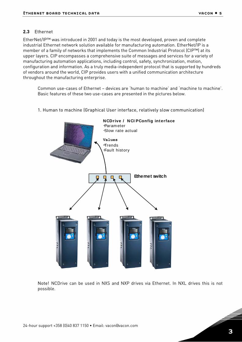
Common use-cases of Ethernet – devices are ‘human to machine’ and ‘machine to machine’. Basic features of these two use-cases are presented in the pictures below. 1. Human to machine (Graphical User interface, relatively slow communication)
Note! NCDrive can be used in NXS and NXP drives via Ethernet. In NXL drives this is not possible.
NCDrive / NCIPConfig interface - Parameter - Slow rate actual
Values - Trends - Fault history
- -
-
Ethernet switch
6 • vacon installation
Tel. +358 (0)201 2121 • Fax +358 (0)201 212 205 3
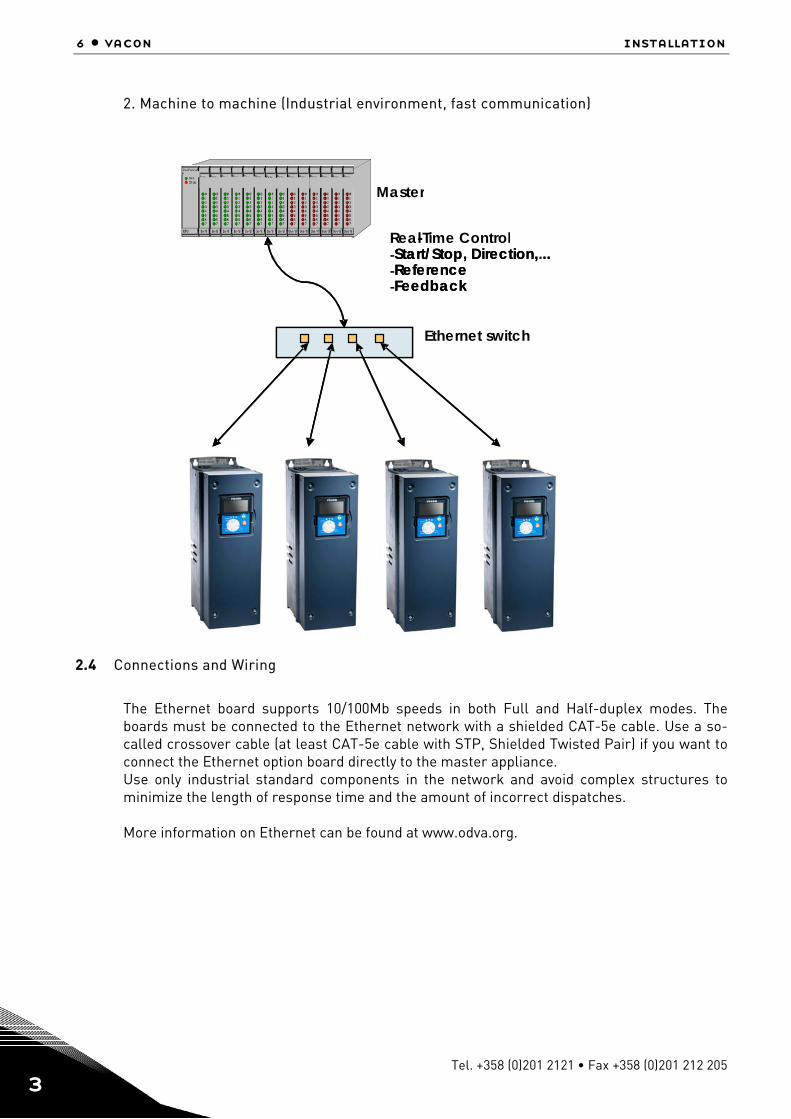
2. Machine to machine (Industrial environment, fast communication)
2.4 Connections and Wiring
The Ethernet board supports 10/100Mb speeds in both Full and Half-duplex modes. The boards must be connected to the Ethernet network with a shielded CAT-5e cable. Use a so-called crossover cable (at least CAT-5e cable with STP, Shielded Twisted Pair) if you want to connect the Ethernet option board directly to the master appliance. Use only industrial standard components in the network and avoid complex structures to minimize the length of response time and the amount of incorrect dispatches.
More information on Ethernet can be found at www.odva.org.
PLC or Programmable Controller
Real - Time Control - Start/Stop, Direction,... - Reference - Feedback
PLC or Programmable Controller PLC or Programmable Controller
-
Master
- Start/Stop, Direction, .. - Reference - Feedback
Ethernet switch
Installation vacon • 7
24-hour support +358 (0)40 837 1150 • Email: [email protected] 3
3. INSTALLATION
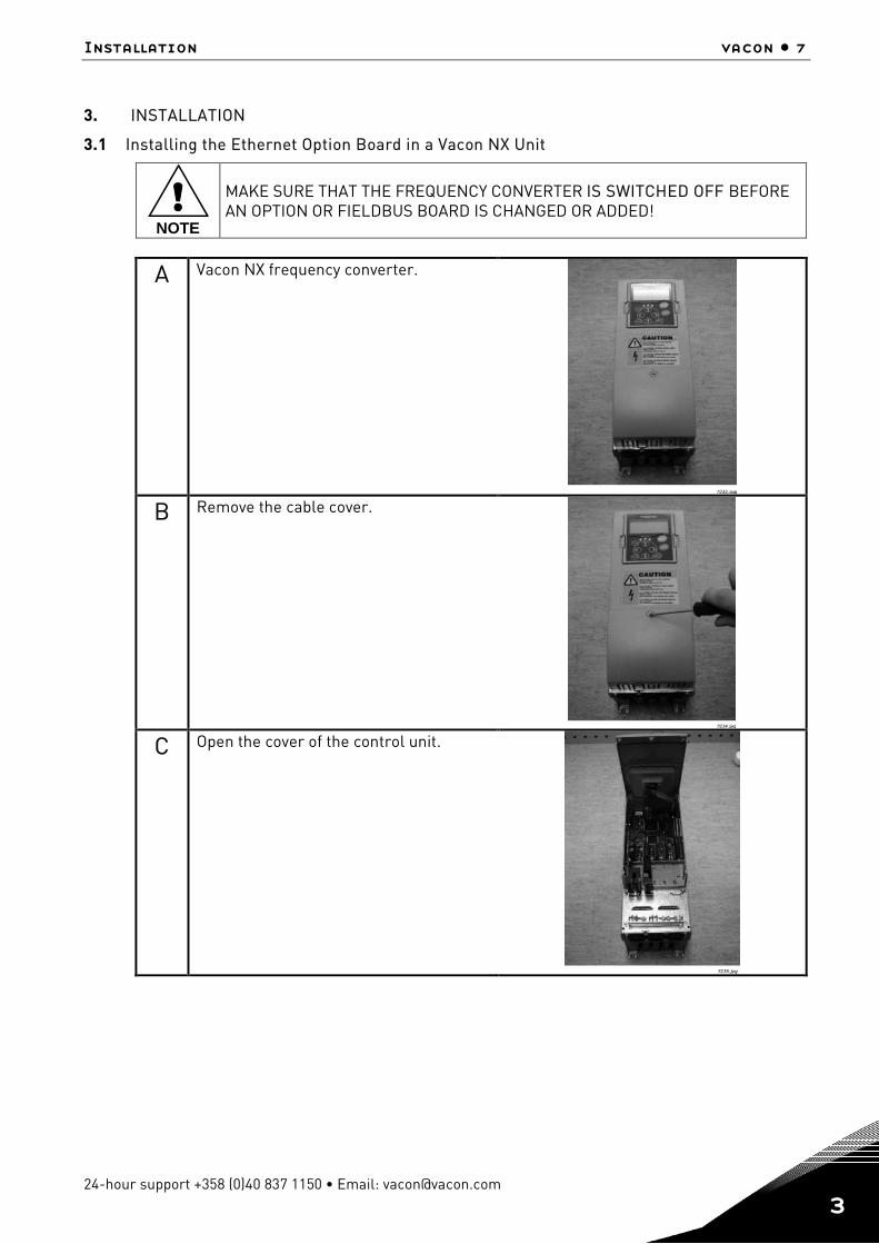
3.1 Installing the Ethernet Option Board in a Vacon NX Unit
!NOTE
MAKE SURE THAT THE FREQUENCY CONVERTER IS SWITCHED OFF BEFORE AN OPTION OR FIELDBUS BOARD IS CHANGED OR ADDED!
A Vacon NX frequency converter.
B Remove the cable cover.
C Open the cover of the control unit.

8 • vacon installation
Tel. +358 (0)201 2121 • Fax +358 (0)201 212 205 3
D Install EtherNet/IP option board in slot D or E on the control board of the frequency converter. Make sure that the grounding plate (see below) fits tightly in the clamp.
E Make a sufficiently wide opening for your cable by cutting the grid as wide as necessary.
F Close the cover of the control unit and the cable cover.
Installation vacon • 9
24-hour support +358 (0)40 837 1150 • Email: [email protected] 3
3.2 NCDrive
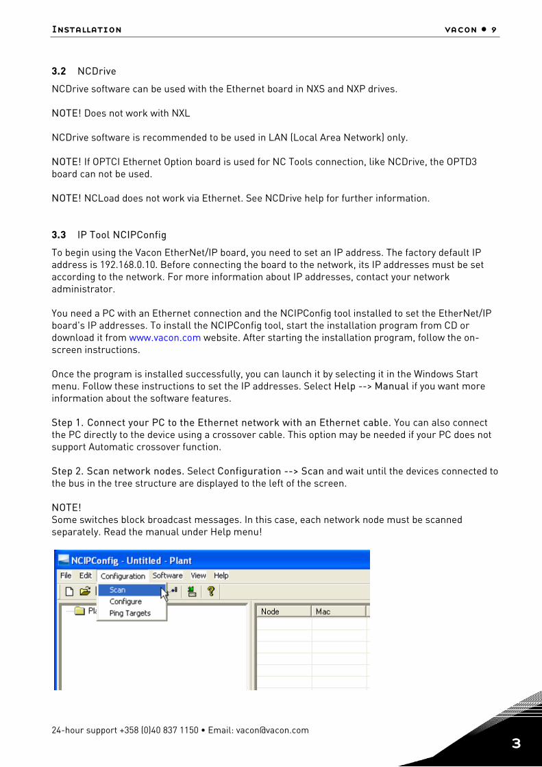
NCDrive software can be used with the Ethernet board in NXS and NXP drives. NOTE! Does not work with NXL NCDrive software is recommended to be used in LAN (Local Area Network) only. NOTE! If OPTCI Ethernet Option board is used for NC Tools connection, like NCDrive, the OPTD3 board can not be used. NOTE! NCLoad does not work via Ethernet. See NCDrive help for further information. 3.3 IP Tool NCIPConfig
To begin using the Vacon EtherNet/IP board, you need to set an IP address. The factory default IP address is 192.168.0.10. Before connecting the board to the network, its IP addresses must be set according to the network. For more information about IP addresses, contact your network administrator. You need a PC with an Ethernet connection and the NCIPConfig tool installed to set the EtherNet/IP board's IP addresses. To install the NCIPConfig tool, start the installation program from CD or download it from www.vacon.com website. After starting the installation program, follow the on-screen instructions. Once the program is installed successfully, you can launch it by selecting it in the Windows Start menu. Follow these instructions to set the IP addresses. Select Help --> Manual if you want more information about the software features. Step 1. Connect your PC to the Ethernet network with an Ethernet cable. You can also connect the PC directly to the device using a crossover cable. This option may be needed if your PC does not support Automatic crossover function. Step 2. Scan network nodes. Select Configuration --> Scan and wait until the devices connected to the bus in the tree structure are displayed to the left of the screen. NOTE! Some switches block broadcast messages. In this case, each network node must be scanned separately. Read the manual under Help menu!
10 • vacon installation
Tel. +358 (0)201 2121 • Fax +358 (0)201 212 205 3
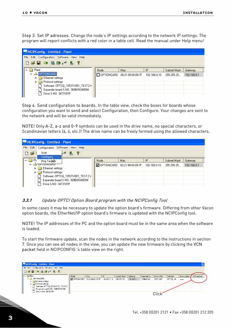
Step 3. Set IP adresses. Change the node’s IP settings according to the network IP settings. The program will report conflicts with a red color in a table cell. Read the manual under Help menu!
Step 4. Send configuration to boards. In the table view, check the boxes for boards whose configuration you want to send and select Configuration, then Configure. Your changes are sent to the network and will be valid immediately. NOTE! Only A-Z, a-z and 0-9 symbols can be used in the drive name, no special characters, or Scandinavian letters (ä, ö, etc.)! The drive name can be freely formed using the allowed characters.
3.3.1 Update OPTCI Option Board program with the NCIPConfig Tool
In some cases it may be necessary to update the option board's firmware. Differing from other Vacon option boards, the EtherNet/IP option board's firmware is updated with the NCIPConfig tool. NOTE! The IP addresses of the PC and the option board must be in the same area when the software is loaded. To start the firmware update, scan the nodes in the network according to the instructions in section 7. Once you can see all nodes in the view, you can update the new firmware by clicking the VCN packet field in NCIPCONFIG 's table view on the right.
Click
Installation vacon • 11
24-hour support +358 (0)40 837 1150 • Email: [email protected] 3
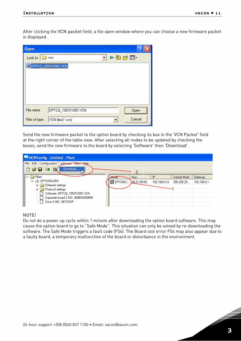
After clicking the VCN packet field, a file open window where you can choose a new firmware packet is displayed.
Send the new firmware packet to the option board by checking its box in the 'VCN Packet' field at the right corner of the table view. After selecting all nodes to be updated by checking the boxes, send the new firmware to the board by selecting 'Software' then 'Download'.
NOTE! Do not do a power up cycle within 1 minute after downloading the option board software. This may cause the option board to go to “Safe Mode”. This situation can only be solved by re-downloading the software. The Safe Mode triggers a fault code (F54). The Board slot error F54 may also appear due to a faulty board, a temporary malfunction of the board or disturbance in the environment.
1
2
12 • vacon installation
Tel. +358 (0)201 2121 • Fax +358 (0)201 212 205 3
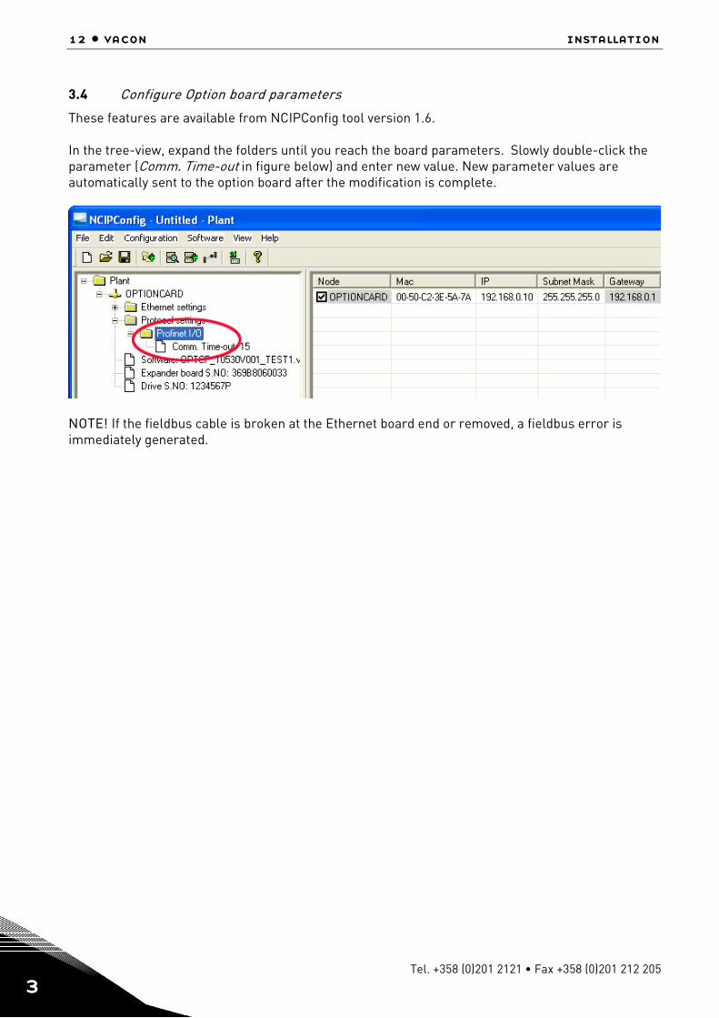
3.4 Configure Option board parameters
These features are available from NCIPConfig tool version 1.6. In the tree-view, expand the folders until you reach the board parameters. Slowly double-click the parameter (Comm. Time-out in figure below) and enter new value. New parameter values are automatically sent to the option board after the modification is complete.
NOTE! If the fieldbus cable is broken at the Ethernet board end or removed, a fieldbus error is immediately generated.
Modbus/tcp vacon • 13
24-hour support +358 (0)40 837 1150 • Email: [email protected] 4
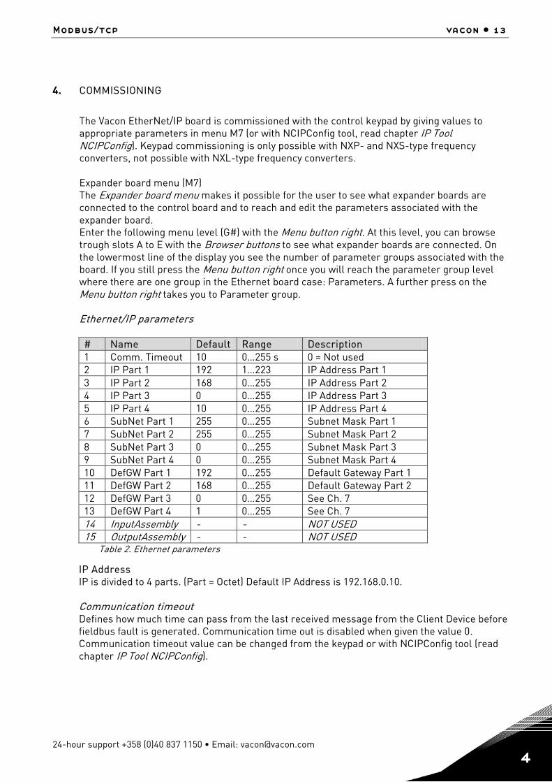
4. COMMISSIONING
The Vacon EtherNet/IP board is commissioned with the control keypad by giving values to appropriate parameters in menu M7 (or with NCIPConfig tool, read chapter IP Tool NCIPConfig). Keypad commissioning is only possible with NXP- and NXS-type frequency converters, not possible with NXL-type frequency converters. Expander board menu (M7) The Expander board menu makes it possible for the user to see what expander boards are connected to the control board and to reach and edit the parameters associated with the expander board. Enter the following menu level (G#) with the Menu button right. At this level, you can browse trough slots A to E with the Browser buttons to see what expander boards are connected. On the lowermost line of the display you see the number of parameter groups associated with the board. If you still press the Menu button right once you will reach the parameter group level where there are one group in the Ethernet board case: Parameters. A further press on the Menu button right takes you to Parameter group. Ethernet/IP parameters # Name Default Range Description 1 Comm. Timeout 10 0…255 s 0 = Not used 2 IP Part 1 192 1…223 IP Address Part 1 3 IP Part 2 168 0…255 IP Address Part 2 4 IP Part 3 0 0…255 IP Address Part 3 5 IP Part 4 10 0…255 IP Address Part 4 6 SubNet Part 1 255 0…255 Subnet Mask Part 1 7 SubNet Part 2 255 0…255 Subnet Mask Part 2 8 SubNet Part 3 0 0…255 Subnet Mask Part 3 9 SubNet Part 4 0 0…255 Subnet Mask Part 4 10 DefGW Part 1 192 0…255 Default Gateway Part 1 11 DefGW Part 2 168 0…255 Default Gateway Part 2 12 DefGW Part 3 0 0…255 See Ch. 7 13 DefGW Part 4 1 0…255 See Ch. 7 14 InputAssembly - - NOT USED 15 OutputAssembly - - NOT USED
Table 2. Ethernet parameters
IP Address IP is divided to 4 parts. (Part = Octet) Default IP Address is 192.168.0.10. Communication timeout Defines how much time can pass from the last received message from the Client Device before fieldbus fault is generated. Communication time out is disabled when given the value 0. Communication timeout value can be changed from the keypad or with NCIPConfig tool (read chapter IP Tool NCIPConfig).
14 • vacon Commissioning
Tel. +358 (0)201 2121 • Fax +358 (0)201 212 205 4
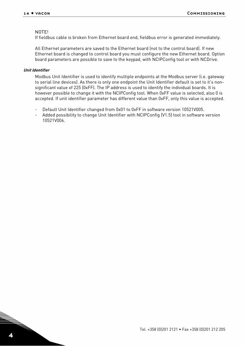
NOTE! If fieldbus cable is broken from Ethernet board end, fieldbus error is generated immediately. All Ethernet parameters are saved to the Ethernet board (not to the control board). If new Ethernet board is changed to control board you must configure the new Ethernet board. Option board parameters are possible to save to the keypad, with NCIPConfig tool or with NCDrive.
Unit Identifier Modbus Unit Identifier is used to identify multiple endpoints at the Modbus server (i.e. gateway to serial line devices). As there is only one endpoint the Unit Identifier default is set to it’s non-significant value of 225 (0xFF). The IP address is used to identify the individual boards. It is however possible to change it with the NCIPConfig tool. When 0xFF value is selected, also 0 is accepted. If unit identifier parameter has different value than 0xFF, only this value is accepted. - Default Unit Identifier changed from 0x01 to 0xFF in software version 10521V005. - Added possibility to change Unit Identifier with NCIPConfig (V1.5) tool in software version
10521V006.
Modbus/tcp vacon • 15
24-hour support +358 (0)40 837 1150 • Email: [email protected] 4
5. MODBUS/TCP
5.1 Overview
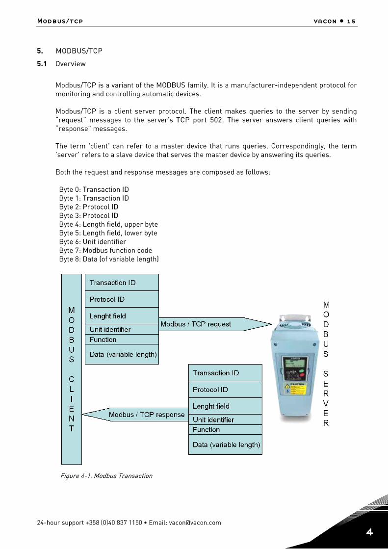
Modbus/TCP is a variant of the MODBUS family. It is a manufacturer-independent protocol for monitoring and controlling automatic devices. Modbus/TCP is a client server protocol. The client makes queries to the server by sending “request” messages to the server's TCP port 502. The server answers client queries with “response” messages. The term 'client' can refer to a master device that runs queries. Correspondingly, the term 'server' refers to a slave device that serves the master device by answering its queries. Both the request and response messages are composed as follows: Byte 0: Transaction ID Byte 1: Transaction ID Byte 2: Protocol ID Byte 3: Protocol ID Byte 4: Length field, upper byte Byte 5: Length field, lower byte Byte 6: Unit identifier Byte 7: Modbus function code Byte 8: Data (of variable length)
Figure 4-1. Modbus Transaction
16 • vacon Commissioning
Tel. +358 (0)201 2121 • Fax +358 (0)201 212 205 4
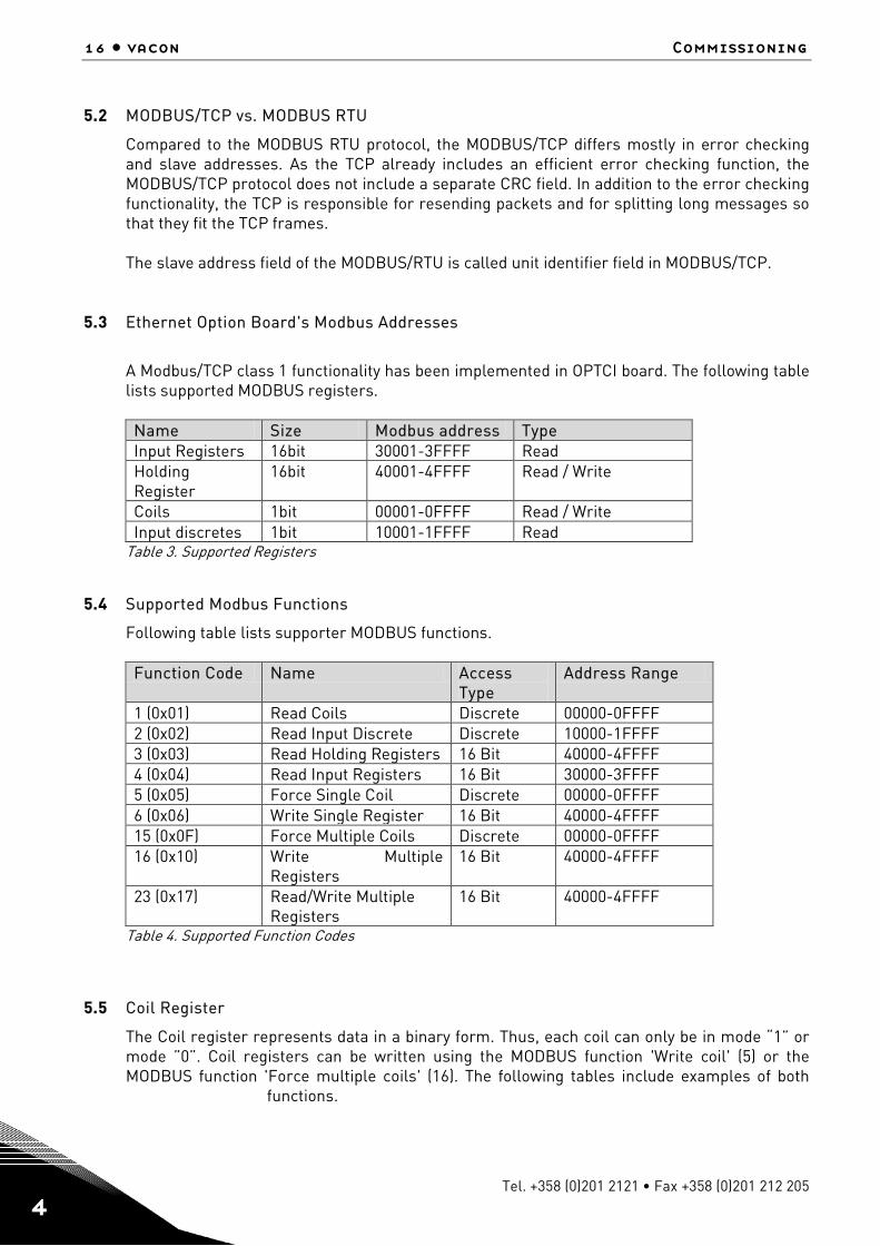
5.2 MODBUS/TCP vs. MODBUS RTU
Compared to the MODBUS RTU protocol, the MODBUS/TCP differs mostly in error checking and slave addresses. As the TCP already includes an efficient error checking function, the MODBUS/TCP protocol does not include a separate CRC field. In addition to the error checking functionality, the TCP is responsible for resending packets and for splitting long messages so that they fit the TCP frames. The slave address field of the MODBUS/RTU is called unit identifier field in MODBUS/TCP.
5.3 Ethernet Option Board's Modbus Addresses
A Modbus/TCP class 1 functionality has been implemented in OPTCI board. The following table lists supported MODBUS registers.
Name Size Modbus address Type Input Registers 16bit 30001-3FFFF Read Holding Register
16bit 40001-4FFFF Read / Write
Coils 1bit 00001-0FFFF Read / Write Input discretes 1bit 10001-1FFFF Read
Table 3. Supported Registers
5.4 Supported Modbus Functions
Following table lists supporter MODBUS functions.
Function Code Name Access Type
Address Range
1 (0x01) Read Coils Discrete 00000-0FFFF 2 (0x02) Read Input Discrete Discrete 10000-1FFFF 3 (0x03) Read Holding Registers 16 Bit 40000-4FFFF 4 (0x04) Read Input Registers 16 Bit 30000-3FFFF 5 (0x05) Force Single Coil Discrete 00000-0FFFF 6 (0x06) Write Single Register 16 Bit 40000-4FFFF 15 (0x0F) Force Multiple Coils Discrete 00000-0FFFF 16 (0x10) Write Multiple
Registers 16 Bit 40000-4FFFF
23 (0x17) Read/Write Multiple Registers
16 Bit 40000-4FFFF
Table 4. Supported Function Codes
5.5 Coil Register
The Coil register represents data in a binary form. Thus, each coil can only be in mode “1” or mode ”0”. Coil registers can be written using the MODBUS function 'Write coil' (5) or the MODBUS function 'Force multiple coils' (16). The following tables include examples of both
functions.
Modbus/tcp vacon • 17
24-hour support +358 (0)40 837 1150 • Email: [email protected] 4
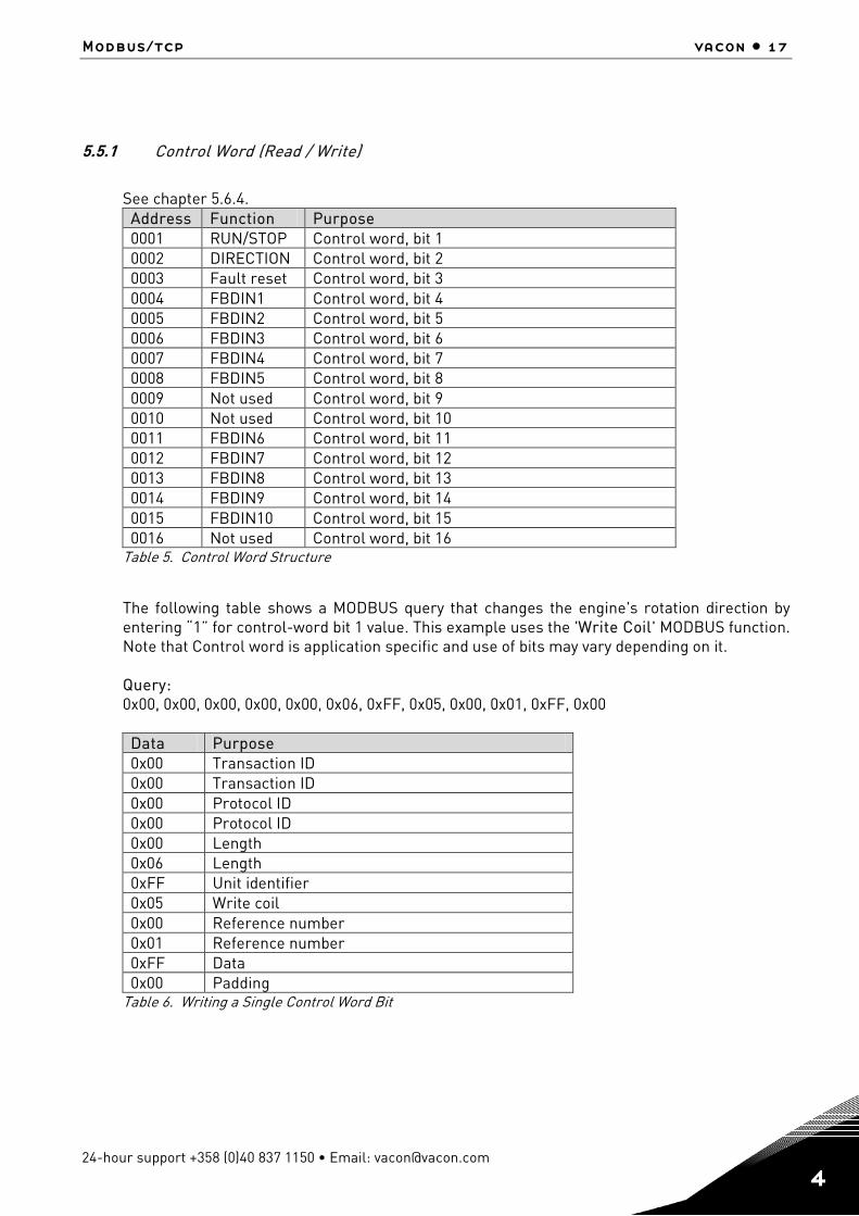
5.5.1 Control Word (Read / Write)
See chapter 5.6.4.
Address Function Purpose 0001 RUN/STOP Control word, bit 1 0002 DIRECTION Control word, bit 2 0003 Fault reset Control word, bit 3 0004 FBDIN1 Control word, bit 4 0005 FBDIN2 Control word, bit 5 0006 FBDIN3 Control word, bit 6 0007 FBDIN4 Control word, bit 7 0008 FBDIN5 Control word, bit 8 0009 Not used Control word, bit 9 0010 Not used Control word, bit 10 0011 FBDIN6 Control word, bit 11 0012 FBDIN7 Control word, bit 12 0013 FBDIN8 Control word, bit 13 0014 FBDIN9 Control word, bit 14 0015 FBDIN10 Control word, bit 15 0016 Not used Control word, bit 16
Table 5. Control Word Structure
The following table shows a MODBUS query that changes the engine's rotation direction by entering “1” for control-word bit 1 value. This example uses the 'Write Coil' MODBUS function. Note that Control word is application specific and use of bits may vary depending on it. Query: 0x00, 0x00, 0x00, 0x00, 0x00, 0x06, 0xFF, 0x05, 0x00, 0x01, 0xFF, 0x00
Data Purpose 0x00 Transaction ID 0x00 Transaction ID 0x00 Protocol ID 0x00 Protocol ID 0x00 Length 0x06 Length 0xFF Unit identifier 0x05 Write coil 0x00 Reference number 0x01 Reference number 0xFF Data 0x00 Padding
Table 6. Writing a Single Control Word Bit

18 • vacon Commissioning
Tel. +358 (0)201 2121 • Fax +358 (0)201 212 205 4
5.5.2 Clearing trip counters
The frequency converter's operation day trip counter and energy trip counter can be reset by entering “1” as the value of the coil in request. When the value “1” is entered, the device resets the counter. However, the device does not change the Coil value after reset but maintains the “0” mode.
Address Function Purpose 0017 ClearOpDay Clears OpDay counter 0018 ClearMWh Clears MWh counter
Table 7. Counters
The following table represents a MODBUS query that resets both counters simultaneously. This example applies the 'Force Multiple Coils' function. The reference number indicates the address after which the amount of data defined by the 'Bit Count' is written. This data is the last block in the MODBUS/TCP message.
Data Purpose 0x00 Transaction ID 0x00 Transaction ID 0x00 Protocol ID 0x00 Protocol ID 0x00 Length 0x08 Length 0xFF Unit identifier 0x0F Force multiple coils 0x00 Reference number 0x10 Reference number 0x00 Bit count 0x02 Bit count 0x01 ByteCount 0x03 Data
Table 8. Force Multiple Coils Query
5.6 Input Discrete
Both the 'Coil register' and the 'Input discrete register' contain binary data. However, the difference between the two registers is that the Input register's data can only be read. The Vacon Ethernet board's MODBUS/TCP implementation uses the following Input discrete addresses.
Modbus/tcp vacon • 19
24-hour support +358 (0)40 837 1150 • Email: [email protected] 4
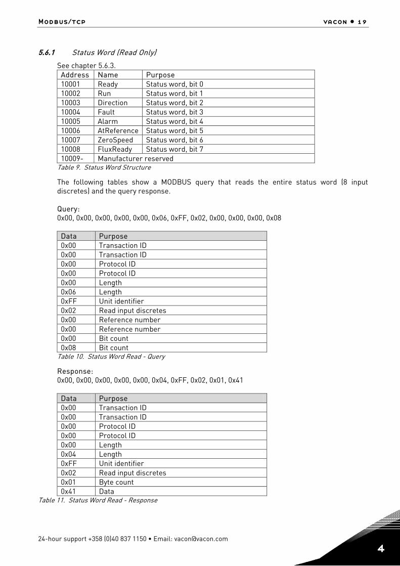
5.6.1 Status Word (Read Only)
See chapter 5.6.3. Address Name Purpose 10001 Ready Status word, bit 0 10002 Run Status word, bit 1 10003 Direction Status word, bit 2 10004 Fault Status word, bit 3 10005 Alarm Status word, bit 4 10006 AtReference Status word, bit 5 10007 ZeroSpeed Status word, bit 6 10008 FluxReady Status word, bit 7 10009- Manufacturer reserved
Table 9. Status Word Structure
The following tables show a MODBUS query that reads the entire status word (8 input discretes) and the query response. Query: 0x00, 0x00, 0x00, 0x00, 0x00, 0x06, 0xFF, 0x02, 0x00, 0x00, 0x00, 0x08
Data Purpose 0x00 Transaction ID 0x00 Transaction ID 0x00 Protocol ID 0x00 Protocol ID 0x00 Length 0x06 Length 0xFF Unit identifier 0x02 Read input discretes 0x00 Reference number 0x00 Reference number 0x00 Bit count 0x08 Bit count
Table 10. Status Word Read - Query
Response: 0x00, 0x00, 0x00, 0x00, 0x00, 0x04, 0xFF, 0x02, 0x01, 0x41
Data Purpose 0x00 Transaction ID 0x00 Transaction ID 0x00 Protocol ID 0x00 Protocol ID 0x00 Length 0x04 Length 0xFF Unit identifier 0x02 Read input discretes 0x01 Byte count 0x41 Data
Table 11. Status Word Read - Response
20 • vacon Commissioning
Tel. +358 (0)201 2121 • Fax +358 (0)201 212 205 4
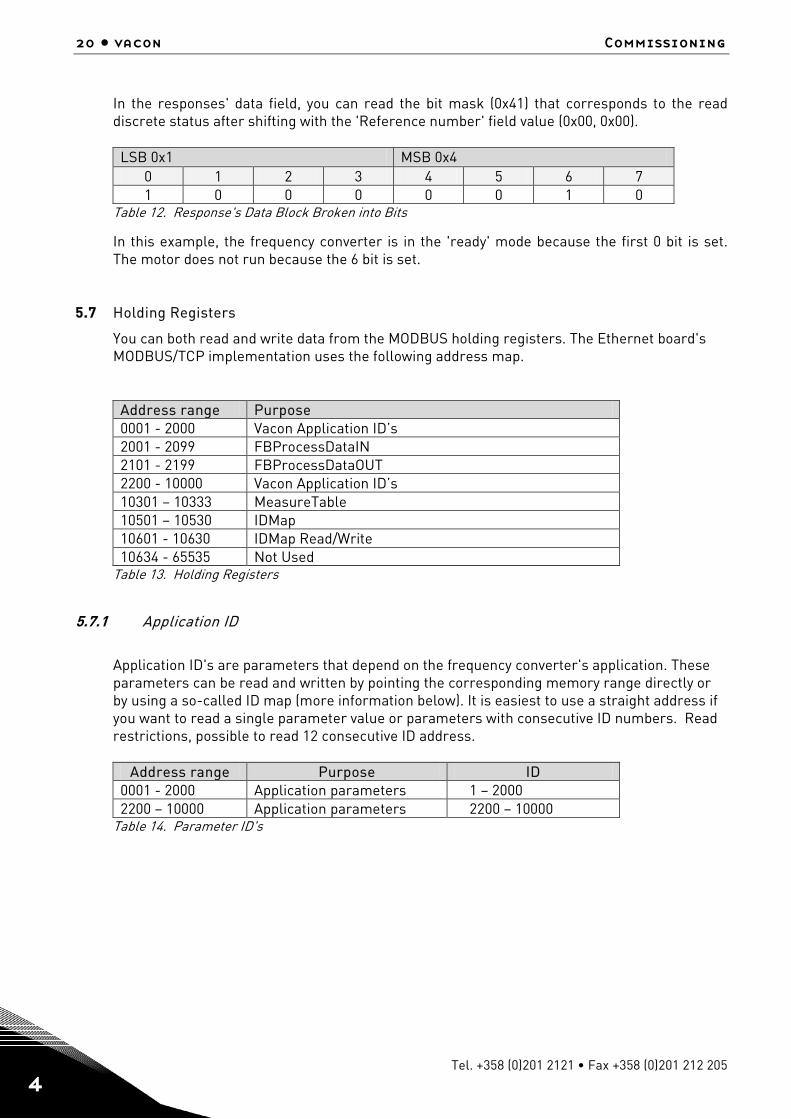
In the responses' data field, you can read the bit mask (0x41) that corresponds to the read discrete status after shifting with the 'Reference number' field value (0x00, 0x00).
LSB 0x1 MSB 0x4 0 1 2 3 4 5 6 7 1 0 0 0 0 0 1 0
Table 12. Response's Data Block Broken into Bits
In this example, the frequency converter is in the 'ready' mode because the first 0 bit is set. The motor does not run because the 6 bit is set.
5.7 Holding Registers
You can both read and write data from the MODBUS holding registers. The Ethernet board's MODBUS/TCP implementation uses the following address map.
Address range Purpose 0001 - 2000 Vacon Application ID’s 2001 - 2099 FBProcessDataIN 2101 - 2199 FBProcessDataOUT 2200 - 10000 Vacon Application ID’s 10301 – 10333 MeasureTable 10501 – 10530 IDMap 10601 - 10630 IDMap Read/Write 10634 - 65535 Not Used
Table 13. Holding Registers
5.7.1 Application ID
Application ID's are parameters that depend on the frequency converter's application. These parameters can be read and written by pointing the corresponding memory range directly or by using a so-called ID map (more information below). It is easiest to use a straight address if you want to read a single parameter value or parameters with consecutive ID numbers. Read restrictions, possible to read 12 consecutive ID address.
Address range Purpose ID 0001 - 2000 Application parameters 1 – 2000 2200 – 10000 Application parameters 2200 – 10000
Table 14. Parameter ID's
Modbus/tcp vacon • 21
24-hour support +358 (0)40 837 1150 • Email: [email protected] 4
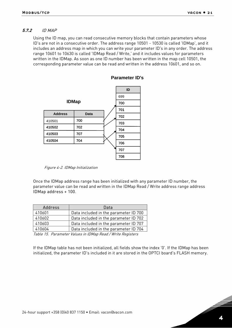
5.7.2 ID MAP
Using the ID map, you can read consecutive memory blocks that contain parameters whose ID's are not in a consecutive order. The address range 10501 - 10530 is called 'IDMap', and it includes an address map in which you can write your parameter ID's in any order. The address range 10601 to 10630 is called 'IDMap Read / Write,' and it includes values for parameters written in the IDMap. As soon as one ID number has been written in the map cell 10501, the corresponding parameter value can be read and written in the address 10601, and so on.
Figure 4-2. IDMap Initialization
Once the IDMap address range has been initialized with any parameter ID number, the parameter value can be read and written in the IDMap Read / Write address range address IDMap address + 100.
Address Data 410601 Data included in the parameter ID 700 410602 Data included in the parameter ID 702 410603 Data included in the parameter ID 707 410604 Data included in the parameter ID 704
Table 15. Parameter Values in IDMap Read / Write Registers
If the IDMap table has not been initialized, all fields show the index '0'. If the IDMap has been initialized, the parameter ID's included in it are stored in the OPTCI board's FLASH memory.
704 410504
707 410503
702 410502
700
Data Address
704 410504
707 410503
702 410502
700
Data Address
708
707
706
705
704
703
702
701
700
699
ID
708
707
706
705
704
703
702
701
700
ID
IDMap
Parameter ID's
410501
22 • vacon Commissioning
Tel. +358 (0)201 2121 • Fax +358 (0)201 212 205 4
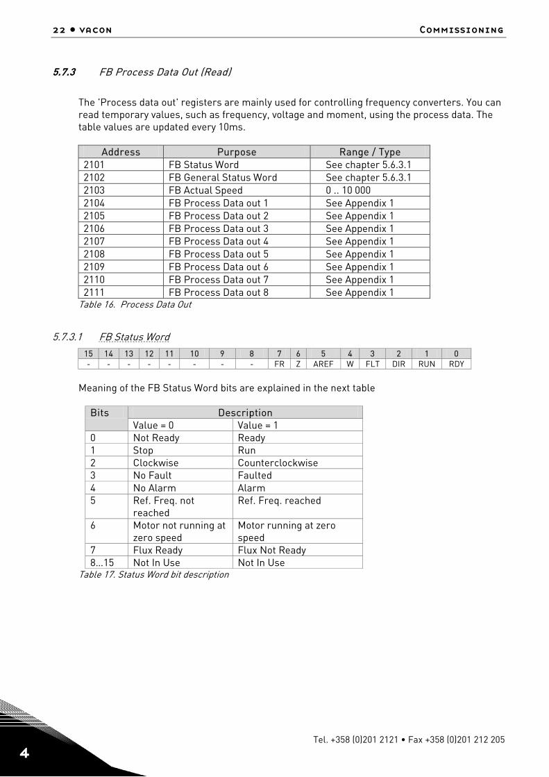
5.7.3 FB Process Data Out (Read)
The 'Process data out' registers are mainly used for controlling frequency converters. You can read temporary values, such as frequency, voltage and moment, using the process data. The table values are updated every 10ms.
Address Purpose Range / Type
2101 FB Status Word See chapter 5.6.3.1 2102 FB General Status Word See chapter 5.6.3.1 2103 FB Actual Speed 0 .. 10 000 2104 FB Process Data out 1 See Appendix 1 2105 FB Process Data out 2 See Appendix 1 2106 FB Process Data out 3 See Appendix 1 2107 FB Process Data out 4 See Appendix 1 2108 FB Process Data out 5 See Appendix 1 2109 FB Process Data out 6 See Appendix 1 2110 FB Process Data out 7 See Appendix 1 2111 FB Process Data out 8 See Appendix 1
Table 16. Process Data Out
5.7.3.1 FB Status Word
15 14 13 12 11 10 9 8 7 6 5 4 3 2 1 0 - - - - - - - - FR Z AREF W FLT DIR RUN RDY
Meaning of the FB Status Word bits are explained in the next table
Bits Description Value = 0 Value = 1
0 Not Ready Ready 1 Stop Run 2 Clockwise Counterclockwise 3 No Fault Faulted 4 No Alarm Alarm 5 Ref. Freq. not
reached Ref. Freq. reached
6 Motor not running at zero speed
Motor running at zero speed
7 Flux Ready Flux Not Ready 8…15 Not In Use Not In Use
Table 17. Status Word bit description
Modbus/tcp vacon • 23
24-hour support +358 (0)40 837 1150 • Email: [email protected] 4
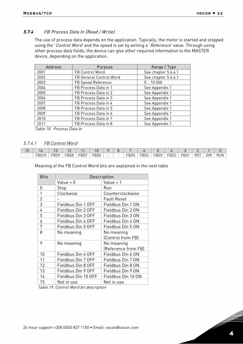
5.7.4 FB Process Data In (Read / Write)
The use of process data depends on the application. Typically, the motor is started and stopped using the 'Control Word' and the speed is set by writing a 'Reference' value. Through using other process data fields, the device can give other required information to the MASTER device, depending on the application.
Address Purpose Range / Type 2001 FB Control Word See chapter 5.6.4.1 2002 FB General Control Word See chapter 5.6.4.1 2003 FB Speed Reference 0 .. 10 000 2004 FB Process Data in 1 See Appendix 1 2005 FB Process Data in 2 See Appendix 1 2006 FB Process Data in 3 See Appendix 1 2007 FB Process Data in 4 See Appendix 1 2008 FB Process Data in 5 See Appendix 1 2009 FB Process Data in 6 See Appendix 1 2010 FB Process Data in 7 See Appendix 1 2011 FB Process Data in 8 See Appendix 1
Table 18. Process Data In
5.7.4.1 FB Control Word
15 14 13 12 11 10 9 8 7 6 5 4 3 2 1 0 - FBD10 FBD9 FBD8 FBD7 FBD6 - - FBD5 FBD4 FBD3 FBD2 FBD1 RST DIR RUN
Meaning of the FB Control Word bits are explained in the next table
Bits Description Value = 0 Value = 1
0 Stop Run 1 Clockwise Counterclockwise 2 - Fault Reset 3 Fieldbus Din 1 OFF Fieldbus Din 1 ON 4 Fieldbus Din 2 OFF Fieldbus Din 2 ON 5 Fieldbus Din 3 OFF Fieldbus Din 3 ON 6 Fieldbus Din 4 OFF Fieldbus Din 4 ON 7 Fieldbus Din 5 OFF Fieldbus Din 5 ON 8 No meaning No meaning
(Control from FB) 9 No meaning No meaning
(Reference from FB) 10 Fieldbus Din 6 OFF Fieldbus Din 6 ON 11 Fieldbus Din 7 OFF Fieldbus Din 7 ON 12 Fieldbus Din 8 OFF Fieldbus Din 8 ON 13 Fieldbus Din 9 OFF Fieldbus Din 9 ON 14 Fieldbus Din 10 OFF Fieldbus Din 10 ON 15 Not in use Not in use
Table 19. Control Word bit description
24 • vacon Commissioning
Tel. +358 (0)201 2121 • Fax +358 (0)201 212 205 4
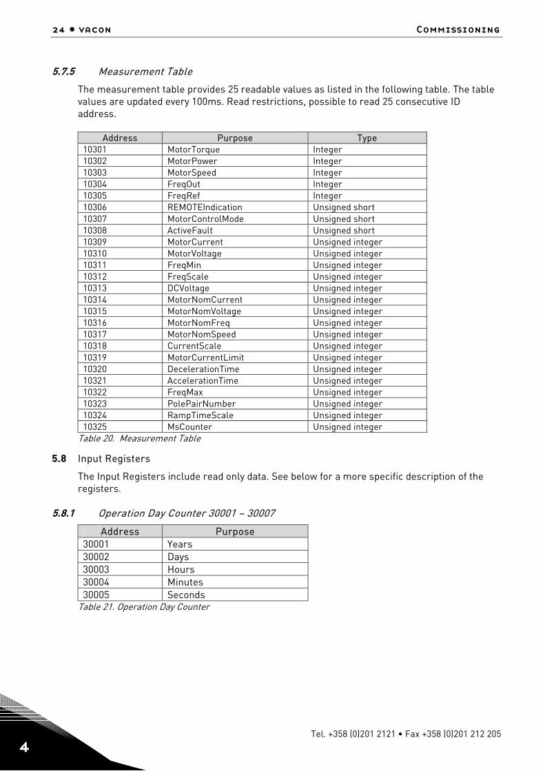
5.7.5 Measurement Table
The measurement table provides 25 readable values as listed in the following table. The table values are updated every 100ms. Read restrictions, possible to read 25 consecutive ID address.
Address Purpose Type 10301 MotorTorque Integer 10302 MotorPower Integer 10303 MotorSpeed Integer 10304 FreqOut Integer 10305 FreqRef Integer 10306 REMOTEIndication Unsigned short 10307 MotorControlMode Unsigned short 10308 ActiveFault Unsigned short 10309 MotorCurrent Unsigned integer 10310 MotorVoltage Unsigned integer 10311 FreqMin Unsigned integer 10312 FreqScale Unsigned integer 10313 DCVoltage Unsigned integer 10314 MotorNomCurrent Unsigned integer 10315 MotorNomVoltage Unsigned integer 10316 MotorNomFreq Unsigned integer 10317 MotorNomSpeed Unsigned integer 10318 CurrentScale Unsigned integer 10319 MotorCurrentLimit Unsigned integer 10320 DecelerationTime Unsigned integer 10321 AccelerationTime Unsigned integer 10322 FreqMax Unsigned integer 10323 PolePairNumber Unsigned integer 10324 RampTimeScale Unsigned integer 10325 MsCounter Unsigned integer
Table 20. Measurement Table
5.8 Input Registers
The Input Registers include read only data. See below for a more specific description of the registers.
5.8.1 Operation Day Counter 30001 – 30007
Address Purpose 30001 Years 30002 Days 30003 Hours 30004 Minutes 30005 Seconds
Table 21. Operation Day Counter

Modbus/tcp vacon • 25
24-hour support +358 (0)40 837 1150 • Email: [email protected] 4
5.8.2 Resettable Operation Day Counter 30101 – 30107
Address Purpose 30101 Years 30102 Days 30103 Hours 30104 Minutes 30105 Seconds
Table 22. Resettable Operation Day Counter
5.8.3 Energy Counter 30201 – 30203
The last number of the 'Format' field indicates the decimal point place in the 'Energy' field. If the number is bigger than 0, move the decimal point to the left by the number indicated. For example, Energy = 1200, Format = 52. Unit = 1. Energy = 12.00kWh
Address Purpose 30201 Energy 30202 Format 30203 Unit
1 = kWh 2 = MWh 3 = GWh 4 = TWh
Table 23. Energy Counter
5.8.4 Resettable Energy Counter 30301 – 30303
Address Purpose 30301 Energy 30302 Format 30303 Unit
1 = kWh 2 = MWh 3 = GWh 4 = TWh
Table 24. Resettable Energy Counter
5.8.5 Fault History 30401 – 30430
The fault history can be viewed by reading from the address 30401 onward. The faults are listed in chronological order so that the latest fault is mentioned first and the oldest is mentioned last. The fault history can contain 29 faults at any time. The fault history contents are represented as follows.
Fault code Sub-code Value as a hexadecimal Value as a hexadecimal
Table 25. Fault Coding

26 • vacon Commissioning
Tel. +358 (0)201 2121 • Fax +358 (0)201 212 205 4
For example, the IGBT temperature fault code 41, sub-code 00: 2900Hex -> 4100Dec. For complete list of fault codes please see frequency converter’s manual Note! It is very slow to read whole fault history (30401-30430) at a time. It is recommended to read only parts of the fault history at a time.
Modbus/tcp vacon • 27
24-hour support +358 (0)40 837 1150 • Email: [email protected] 4
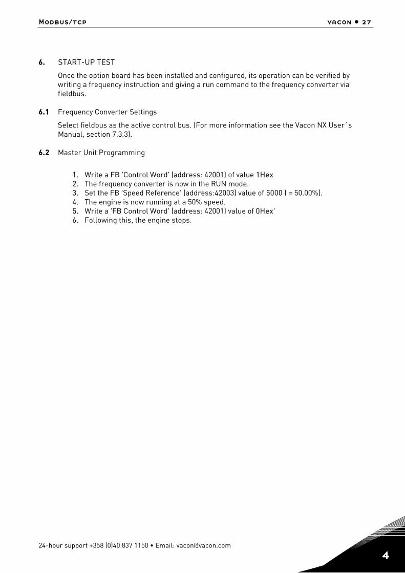
6. START-UP TEST
Once the option board has been installed and configured, its operation can be verified by writing a frequency instruction and giving a run command to the frequency converter via fieldbus.
6.1 Frequency Converter Settings
Select fieldbus as the active control bus. (For more information see the Vacon NX User´s Manual, section 7.3.3).
6.2 Master Unit Programming
1. Write a FB 'Control Word' (address: 42001) of value 1Hex 2. The frequency converter is now in the RUN mode. 3. Set the FB 'Speed Reference' (address:42003) value of 5000 ( = 50.00%). 4. The engine is now running at a 50% speed. 5. Write a 'FB Control Word' (address: 42001) value of 0Hex' 6. Following this, the engine stops.
28 • vacon Error Codes and Errors
Tel. +358 (0)201 2121 • Fax +358 (0)201 212 205 5
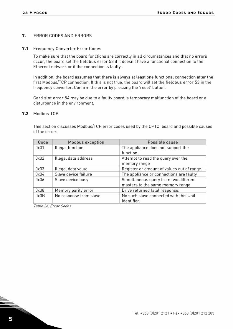
7. ERROR CODES AND ERRORS
7.1 Frequency Converter Error Codes
To make sure that the board functions are correctly in all circumstances and that no errors occur, the board set the fieldbus error 53 if it doesn't have a functional connection to the Ethernet network or if the connection is faulty. In addition, the board assumes that there is always at least one functional connection after the first Modbus/TCP connection. If this is not true, the board will set the fieldbus error 53 in the frequency converter. Confirm the error by pressing the 'reset' button. Card slot error 54 may be due to a faulty board, a temporary malfunction of the board or a disturbance in the environment.
7.2 Modbus TCP
This section discusses Modbus/TCP error codes used by the OPTCI board and possible causes of the errors.
Code Modbus exception Possible cause
0x01 Illegal function The appliance does not support the function
0x02 Illegal data address Attempt to read the query over the memory range
0x03 Illegal data value Register or amount of values out of range. 0x04 Slave device failure The appliance or connections are faulty 0x06 Slave device busy Simultaneous query from two different
masters to the same memory range 0x08 Memory parity error Drive returned fatal response. 0x0B No response from slave No such slave connected with this Unit
Identifier. Table 26. Error Codes
appendix vacon • 29
24-hour support +358 (0)40 837 1150 • Email: [email protected] 7
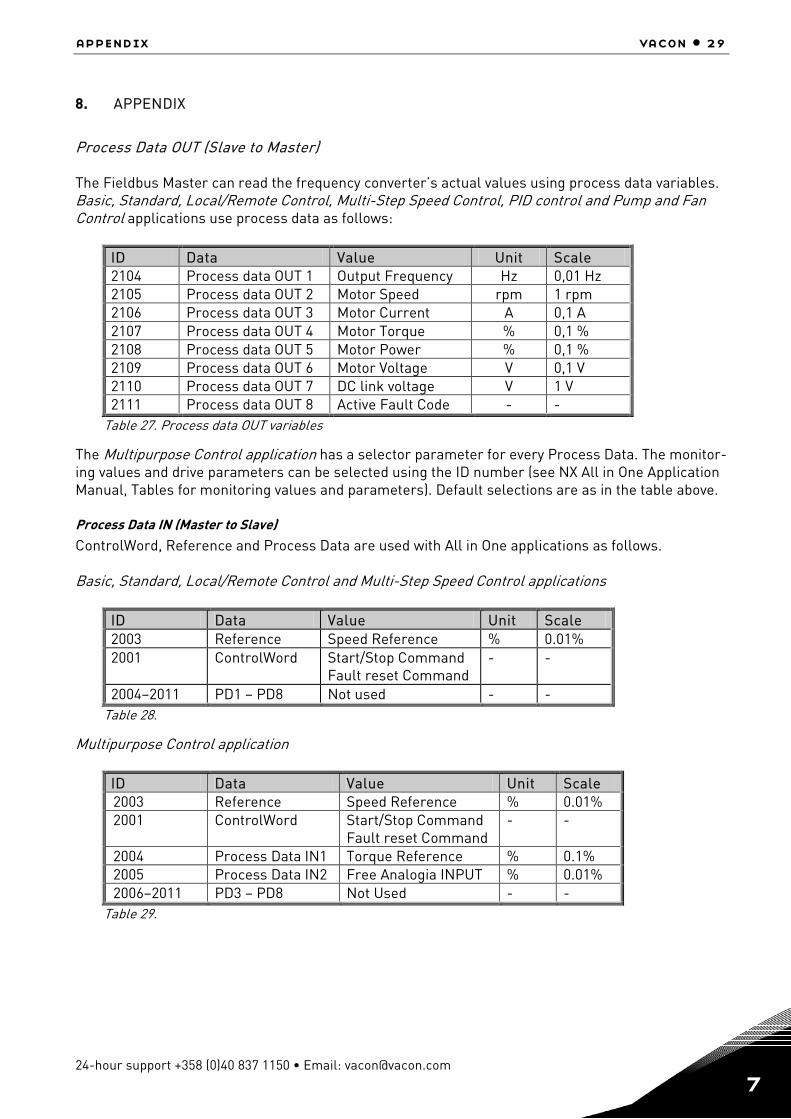
8. APPENDIX
Process Data OUT (Slave to Master) The Fieldbus Master can read the frequency converter’s actual values using process data variables. Basic, Standard, Local/Remote Control, Multi-Step Speed Control, PID control and Pump and Fan Control applications use process data as follows:
ID Data Value Unit Scale 2104 Process data OUT 1 Output Frequency Hz 0,01 Hz 2105 Process data OUT 2 Motor Speed rpm 1 rpm 2106 Process data OUT 3 Motor Current A 0,1 A 2107 Process data OUT 4 Motor Torque % 0,1 % 2108 Process data OUT 5 Motor Power % 0,1 % 2109 Process data OUT 6 Motor Voltage V 0,1 V 2110 Process data OUT 7 DC link voltage V 1 V 2111 Process data OUT 8 Active Fault Code - -
Table 27. Process data OUT variables
The Multipurpose Control application has a selector parameter for every Process Data. The monitor-ing values and drive parameters can be selected using the ID number (see NX All in One Application Manual, Tables for monitoring values and parameters). Default selections are as in the table above. Process Data IN (Master to Slave) ControlWord, Reference and Process Data are used with All in One applications as follows. Basic, Standard, Local/Remote Control and Multi-Step Speed Control applications
ID Data Value Unit Scale 2003 Reference Speed Reference % 0.01% 2001 ControlWord Start/Stop Command
Fault reset Command - -
2004–2011 PD1 – PD8 Not used - - Table 28.
Multipurpose Control application
ID Data Value Unit Scale 2003 Reference Speed Reference % 0.01% 2001 ControlWord Start/Stop Command
Fault reset Command - -
2004 Process Data IN1 Torque Reference % 0.1% 2005 Process Data IN2 Free Analogia INPUT % 0.01% 2006–2011 PD3 – PD8 Not Used - -
Table 29.

30 • vacon Appendix
Tel. +358 (0)201 2121 • Fax +358 (0)201 212 205 7
PID control and Pump and fan control applications
ID Data Value Unit Scale 2003 Reference Speed Reference % 0.01% 2001 ControlWord Start/Stop Command
Fault reset Command - -
2004 Process Data IN1 Reference for PID controller
% 0.01%
2005 Process Data IN2 Actual Value 1 to PID controller
% 0.01%
2006 Process Data IN3 Actual Value 2 to PID controller
% 0.01%
2007–2011 PD4–PD8 Not Used - - Table 30.
License for LWIP Copyright (c) 2001, 2002 Swedish Institute of Computer Science. All rights reserved. Redistribution and use in source and binary forms, with or without modification, are permitted provided that the following conditions are met: 1. Redistributions of source code must retain the above copyright notice, this list of conditions and the following disclaimer. 2. Redistributions in binary form must reproduce the above copyright notice, this list of conditions and the following disclaimer in the documentation and/or other materials provided with the distribution. 3. The name of the author may not be used to endorse or promote products derived from this software without specific prior written permission. THIS SOFTWARE IS PROVIDED BY THE AUTHOR "AS IS" AND ANY EXPRESS OR IMPLIED WARRANTIES, INCLUDING, BUT NOT LIMITED TO, THE IMPLIED WARRANTIES OF MERCHANTABILITY AND FITNESS FOR A PARTICULAR PURPOSE ARE DISCLAIMED. IN NO EVENT SHALL THE AUTHOR BE LIABLE FOR ANY DIRECT, INDIRECT, INCIDENTAL, SPECIAL, EXEMPLARY, OR CONSEQUENTIAL DAMAGES (INCLUDING, BUT NOT LIMITED TO, PROCUREMENT OF SUBSTITUTE GOODS OR SERVICES; LOSS OF USE, DATA, OR PROFITS; OR BUSINESS INTERRUPTION) HOWEVER CAUSED AND ON ANY THEORY OF LIABILITY, WHETHER IN CONTRACT, STRICT LIABILITY, OR TORT (INCLUDING NEGLIGENCE OR OTHERWISE) ARISING IN ANY WAY OUT OF THE USE OF THIS SOFTWARE, EVEN IF ADVISED OF THE POSSIBILITY OF SUCH DAMAGE.


Document ID:
Rev. A
Manual authoring:[email protected]
Vacon Plc.Runsorintie 765380 VaasaFinland
Subject to change without prior notice© 2012 Vacon Plc.
Find your nearest Vacon office on the Internet at:
www.vacon.com
Find your nearest Vacon service centre on the Extranet at:
www.extra.vacon.com