Embed Size (px)
Citation preview

vacon 100ac drives
profibus dp option board opte3/e5user manual

vacon • 1
24-hour support +358 (0)201 212 575 • Email: [email protected]
TABLE OF CONTENTS Document: DPD00997AOrder code: DOC-INS06834+DLUK
Release date : 5.6.2012
1. Safety ............................................................................................................... 21.1 Danger ................................................................................................................................ 21.2 Warnings ............................................................................................................................ 31.3 Earthing and earth fault protection ................................................................................... 4
2. PROFIBUS DP - general .................................................................................... 53. PROFIBUS DP technical data ............................................................................ 63.1 General ............................................................................................................................... 63.2 PROFIBUS DP cable ........................................................................................................... 7
4. Layout, connections and installation ................................................................ 94.1 PROFIBUS OPTE3/E5 option board layout......................................................................... 94.2 Connections........................................................................................................................ 94.3 LED indications................................................................................................................. 104.4 Jumpers ........................................................................................................................... 114.5 Installation in vacon 100.................................................................................................. 124.6 Prepare for use through fieldbus .................................................................................... 14
5. Commissioning ............................................................................................... 185.1 PROFIBUS DP board parameters .................................................................................... 185.1.1 Parameter descriptions ................................................................................................... 18
6. PROFIBUS DP interface .................................................................................. 216.1 General ............................................................................................................................. 216.2 Data mapping for PROFIdrive 4.1 .................................................................................... 236.2.1 PROFIdrive 4.1 state machine.......................................................................................... 236.2.2 Standard telegrams ......................................................................................................... 236.2.3 PROFIdrive Control word (STW1)..................................................................................... 266.2.4 PROFIdrive Status word (ZSW1)....................................................................................... 276.2.5 Setpoint value................................................................................................................... 286.2.6 Actual speed value ........................................................................................................... 296.2.7 Normalization reference parameter ............................................................................... 296.2.8 Shortlist of commands to start the drive......................................................................... 306.2.9 Coding of data signals...................................................................................................... 316.3 Parameter Access in PROFIdrive 4.1............................................................................... 326.3.1 Parameter Access sequence ........................................................................................... 326.3.2 Parameter requests......................................................................................................... 336.3.3 Parameter responses ...................................................................................................... 356.3.4 Example requests and responses ................................................................................... 456.3.5 Supported parameters..................................................................................................... 506.4 Data mapping for PROFIdrive 2.0 .................................................................................... 516.4.1 State machine for PROFIdrive 2.0.................................................................................... 516.4.2 PPO types ......................................................................................................................... 526.5 Parameter Access in PROFIdrive 2.0............................................................................... 536.5.1 DP-V1 with PROFIdrive 2.0............................................................................................... 536.5.2 Parameter field (PKW) in PPO types................................................................................ 536.5.3 Examples .......................................................................................................................... 556.6 Data Mapping in Bypass operate mode ........................................................................... 576.6.1 Bypass control word......................................................................................................... 576.6.2 Bypass status word .......................................................................................................... 576.6.3 Bypass setpoint and actual value .................................................................................... 576.7 Data Mapping in Echo operating mode............................................................................ 58
vacon • 2 Safety
1
1. SAFETY
This manual contains clearly marked cautions and warnings which are intended for your per-sonal safety and to avoid any unintentional damage to the product or connected appliances.
Please read the information included in cautions and warnings carefully.
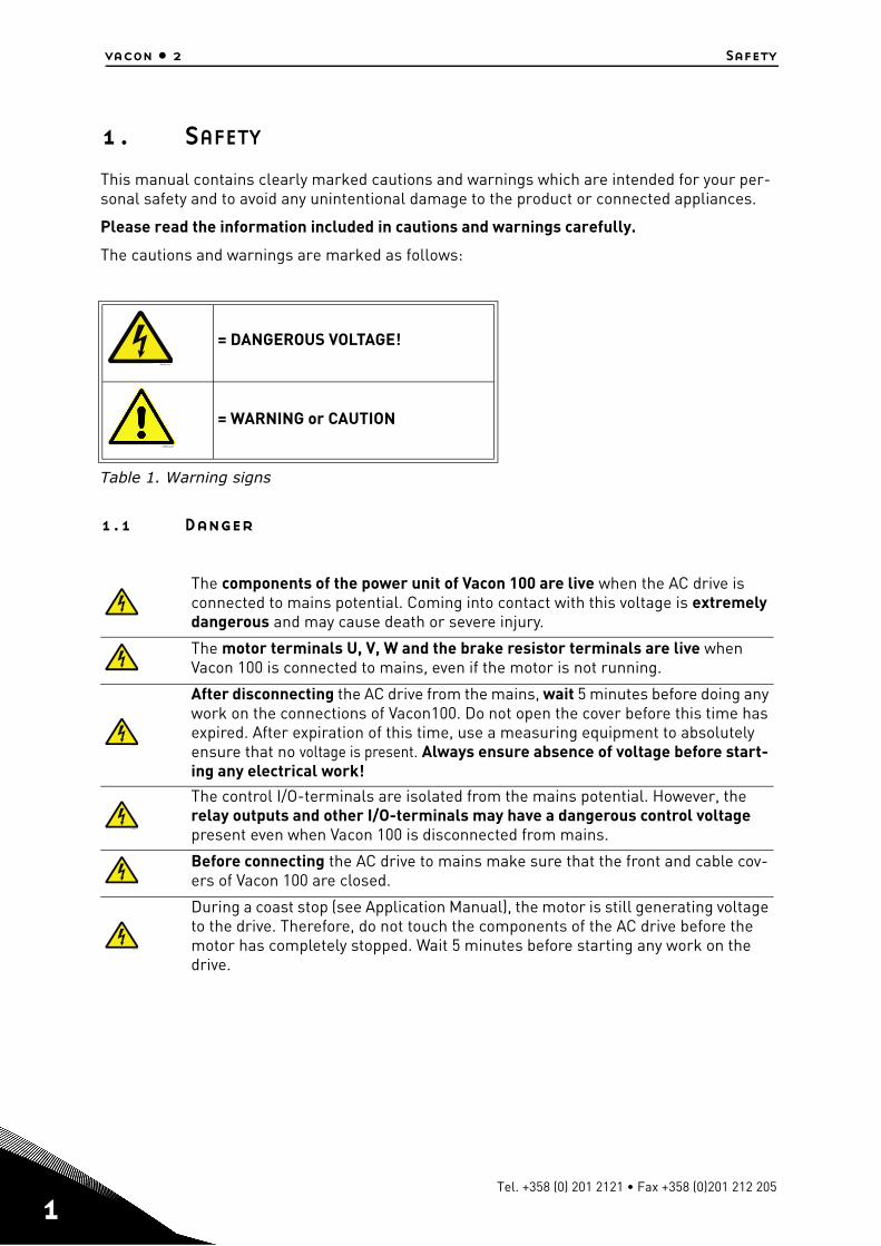
The cautions and warnings are marked as follows:
Table 1. Warning signs
1.1 Danger
= DANGEROUS VOLTAGE!
= WARNING or CAUTION
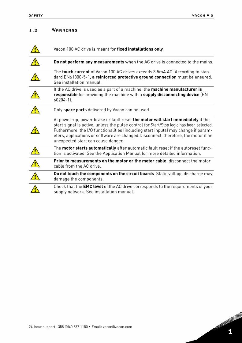
The components of the power unit of Vacon 100 are live when the AC drive is connected to mains potential. Coming into contact with this voltage is extremely dangerous and may cause death or severe injury.
The motor terminals U, V, W and the brake resistor terminals are live when Vacon 100 is connected to mains, even if the motor is not running.
After disconnecting the AC drive from the mains, wait 5 minutes before doing any work on the connections of Vacon100. Do not open the cover before this time has expired. After expiration of this time, use a measuring equipment to absolutely ensure that no voltage is present. Always ensure absence of voltage before start-ing any electrical work!
The control I/O-terminals are isolated from the mains potential. However, the relay outputs and other I/O-terminals may have a dangerous control voltage present even when Vacon 100 is disconnected from mains.
Before connecting the AC drive to mains make sure that the front and cable cov-ers of Vacon 100 are closed.
During a coast stop (see Application Manual), the motor is still generating voltage to the drive. Therefore, do not touch the components of the AC drive before the motor has completely stopped. Wait 5 minutes before starting any work on the drive.
9000.emf
13006.emf
9000.emf
9000.emf
9000.emf
9000.emf
9000.emf
9000.emf
Tel. +358 (0) 201 2121 • Fax +358 (0)201 212 205
Safety vacon • 3
1.2 Warnings
Vacon 100 AC drive is meant for fixed installations only.
Do not perform any measurements when the AC drive is connected to the mains.
The touch current of Vacon 100 AC drives exceeds 3.5mA AC. According to stan-dard EN61800-5-1, a reinforced protective ground connection must be ensured. See installation manual.
If the AC drive is used as a part of a machine, the machine manufacturer is responsible for providing the machine with a supply disconnecting device (EN 60204-1).
Only spare parts delivered by Vacon can be used.
At power-up, power brake or fault reset the motor will start immediately if the start signal is active, unless the pulse control for Start/Stop logic has been selected.Futhermore, the I/O functionalities (including start inputs) may change if param-eters, applications or software are changed.Disconnect, therefore, the motor if an unexpected start can cause danger.
The motor starts automatically after automatic fault reset if the autoreset func-tion is activated. See the Application Manual for more detailed information.
Prior to measurements on the motor or the motor cable, disconnect the motor cable from the AC drive.
Do not touch the components on the circuit boards. Static voltage discharge may damage the components.
Check that the EMC level of the AC drive corresponds to the requirements of your supply network. See installation manual.
13006.emf
13006.emf
13006.emf
13006.emf
13006.emf
13006.emf
13006.emf
13006.emf
13006.emf
13006.emf
24-hour support +358 (0)40 837 1150 • Email: [email protected]
1
vacon • 4 Safety
1
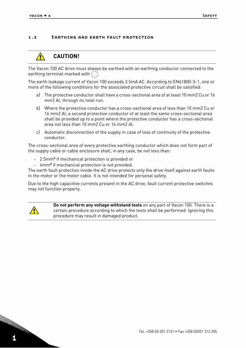
1.3 Earthing and earth fault protection
The Vacon 100 AC drive must always be earthed with an earthing conductor connected to the earthing terminal marked with .
The earth leakage current of Vacon 100 exceeds 3.5mA AC. According to EN61800-5-1, one or more of the following conditions for the associated protective circuit shall be satisfied:
a) The protective conductor shall have a cross-sectional area of at least 10 mm2 Cu or 16 mm2 Al, through its total run.
b) Where the protective conductor has a cross-sectional area of less than 10 mm2 Cu or 16 mm2 Al, a second protective conductor of at least the same cross-sectional area shall be provided up to a point where the protective conductor has a cross-sectional area not less than 10 mm2 Cu or 16 mm2 Al.
c) Automatic disconnection of the supply in case of loss of continuity of the protective conductor.
The cross-sectional area of every protective earthing conductor which does not form part of the supply cable or cable enclosure shall, in any case, be not less than:
- 2.5mm2 if mechanical protection is provided or- 4mm2 if mechanical protection is not provided.
The earth fault protection inside the AC drive protects only the drive itself against earth faults in the motor or the motor cable. It is not intended for personal safety.
Due to the high capacitive currents present in the AC drive, fault current protective switches may not function properly.
CAUTION!
Do not perform any voltage withstand tests on any part of Vacon 100. There is a certain procedure according to which the tests shall be performed. Ignoring this procedure may result in damaged product.
13006.emf
13006.emf
Tel. +358 (0) 201 2121 • Fax +358 (0)201 212 205
PROFIBUS DP - general vacon • 5
24-hour support +358 (0)40 837 1150 • Email: [email protected]
2
2. PROFIBUS DP - GENERAL
Vacon 100 frequency converters can be connected to the PROFIBUS DP network using a field-bus board. The converter can then be controlled, monitored and programmed from the Host system.
PROFIBUS DP uses Master-Slave type communication. Master devices control the communi-cation. The master can send data without a separate command if a token is given to the Master. Slave devices are peripheral devices. Typical slave devices include input/output devices, valves, drives and measuring transmitters. They do not have bus access rights and they can only acknowledge received messages or send messages to the master when requested to do so.
OPTE5/E3 option board also supports connection from DP Master (class 2) if DP-V1 is enabled. In this case, the Master class 2 can initiate a connection, read and write parameters using the PROFIdrive Parameter Access service, and close the connection.
List of abbreviations used in this manual:
Abbreviation ExplanationFB FieldbusDP Decentralized Periphery
PPO Parameter Process Data ObjectCW Control WordSW Status WordPLC Programmable Logic ControllerGSD Generic Station Description
3.
vacon • 6 PROFIBUS DP technical data
3. PROFIBUS DP TECHNICAL DATA
3.1 General
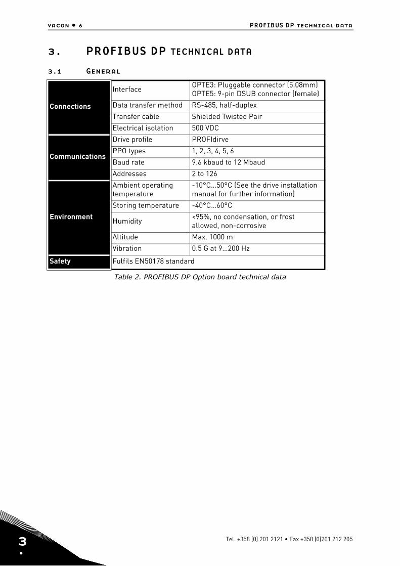
Table 2. PROFIBUS DP Option board technical data
Connections
Interface OPTE3: Pluggable connector (5.08mm)OPTE5: 9-pin DSUB connector (female)
Data transfer method RS-485, half-duplex
Transfer cable Shielded Twisted Pair
Electrical isolation 500 VDC
Communications
Drive profile PROFIdirve
PPO types 1, 2, 3, 4, 5, 6
Baud rate 9.6 kbaud to 12 Mbaud
Addresses 2 to 126
Environment
Ambient operating temperature
-10°C…50°C (See the drive installation manual for further information)
Storing temperature -40°C…60°C
Humidity <95%, no condensation, or frost allowed, non-corrosive
Altitude Max. 1000 m
Vibration 0.5 G at 9…200 Hz
Safety Fulfils EN50178 standard
Tel. +358 (0) 201 2121 • Fax +358 (0)201 212 205
PROFIBUS DP technical data vacon • 7
3.2 PROFIBUS DP cable
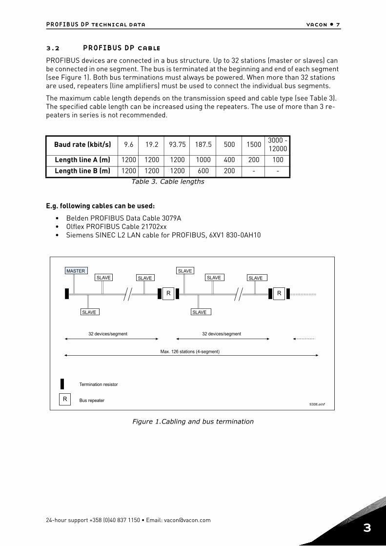
PROFIBUS devices are connected in a bus structure. Up to 32 stations (master or slaves) can be connected in one segment. The bus is terminated at the beginning and end of each segment (see Figure 1). Both bus terminations must always be powered. When more than 32 stations are used, repeaters (line amplifiers) must be used to connect the individual bus segments.
The maximum cable length depends on the transmission speed and cable type (see Table 3). The specified cable length can be increased using the repeaters. The use of more than 3 re-peaters in series is not recommended.
E.g. following cables can be used:
• Belden PROFIBUS Data Cable 3079A• Olflex PROFIBUS Cable 21702xx• Siemens SINEC L2 LAN cable for PROFIBUS, 6XV1 830-0AH10
Figure 1.Cabling and bus termination
Baud rate (kbit/s) 9.6 19.2 93.75 187.5 500 1500 3000 - 12000
Length line A (m) 1200 1200 1200 1000 400 200 100
Length line B (m) 1200 1200 1200 600 200 - -Table 3. Cable lengths
R R
R
Max. 126 stations (4-segment)
Termination resistor
Bus repeater
32 devices/segment
MASTER
SLAVE
SLAVESLAVE
SLAVE
SLAVE
SLAVE SLAVE
9308.emf
32 devices/segment
24-hour support +358 (0)40 837 1150 • Email: [email protected]
3
4
vacon • 9 Layout, connections and installation
4. LAYOUT, CONNECTIONS AND INSTALLATION
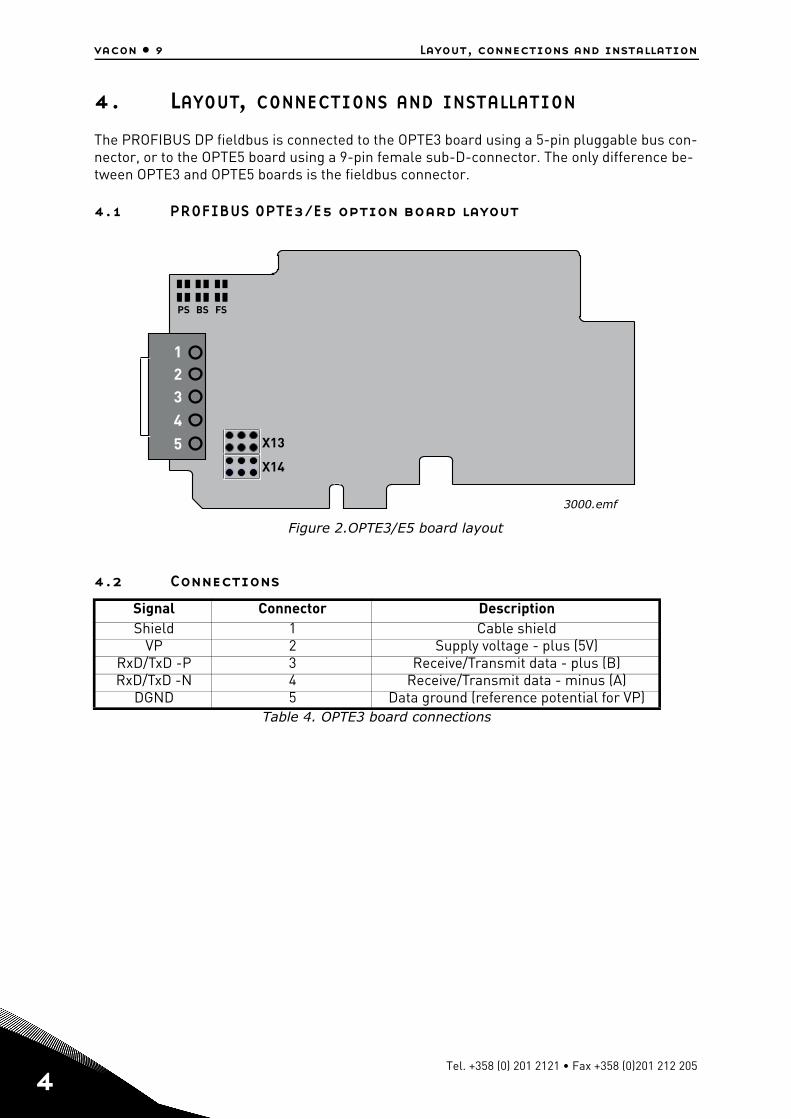
The PROFIBUS DP fieldbus is connected to the OPTE3 board using a 5-pin pluggable bus con-nector, or to the OPTE5 board using a 9-pin female sub-D-connector. The only difference be-tween OPTE3 and OPTE5 boards is the fieldbus connector.
4.1 PROFIBUS OPTE3/E5 option board layout
Figure 2.OPTE3/E5 board layout
4.2 Connections
Signal Connector DescriptionShield 1 Cable shield
VP 2 Supply voltage - plus (5V)RxD/TxD -P 3 Receive/Transmit data - plus (B)RxD/TxD -N 4 Receive/Transmit data - minus (A)
DGND 5 Data ground (reference potential for VP)Table 4. OPTE3 board connections
PS BS FS
12345
3000.emf
X13
X14
Tel. +358 (0) 201 2121 • Fax +358 (0)201 212 205
Layout, connections and installation vacon • 10
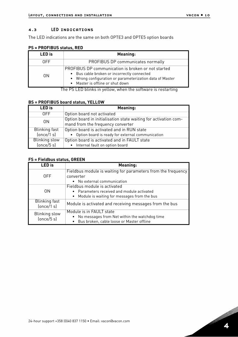
4.3 LED indications
The LED indications are the same on both OPTE3 and OPTE5 option boards
PS = PROFIBUS status, RED
The PS LED blinks in yellow, when the software is restarting
BS = PROFIBUS board status, YELLOW
FS = Fieldbus status, GREEN
LED is Meaning:
OFF PROFIBUS DP communicates normally
ON
PROFIBUS DP communication is broken or not started• Bus cable broken or incorrectly connected• Wrong configuration or parameterization data of Master• Master is offline or shut down
LED is Meaning:OFF Option board not activated
ON Option board in initialisation state waiting for activation com-mand from the frequency converter
Blinking fast (once/1 s)
Option board is activated and in RUN state • Option board is ready for external communication
Blinking slow (once/5 s)
Option board is activated and in FAULT state • Internal fault on option board
LED is Meaning:
OFFFieldbus module is waiting for parameters from the frequency converter
• No external communication
ONFieldbus module is activated
• Parameters received and module activated • Module is waiting for messages from the bus
Blinking fast (once/1 s) Module is activated and receiving messages from the bus
Blinking slow (once/5 s)
Module is in FAULT state • No messages from Net within the watchdog time • Bus broken, cable loose or Master offline
24-hour support +358 (0)40 837 1150 • Email: [email protected]
4
4
vacon • 11 Layout, connections and installation
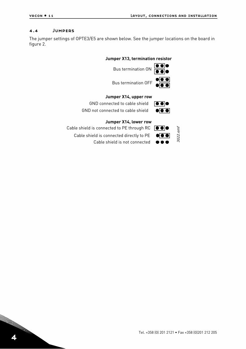
4.4 Jumpers
The jumper settings of OPTE3/E5 are shown below. See the jumper locations on the board in figure 2.
Bus termination ON
GND connected to cable shield
Jumper X13, termination resistor
Cable shield is connected to PE through RC
Cable shield is connected directly to PECable shield is not connected
Bus termination OFF
GND not connected to cable shield
Jumper X14, upper row
Jumper X14, lower row
3022.e
mf
Tel. +358 (0) 201 2121 • Fax +358 (0)201 212 205
Layout, connections and installation vacon • 12
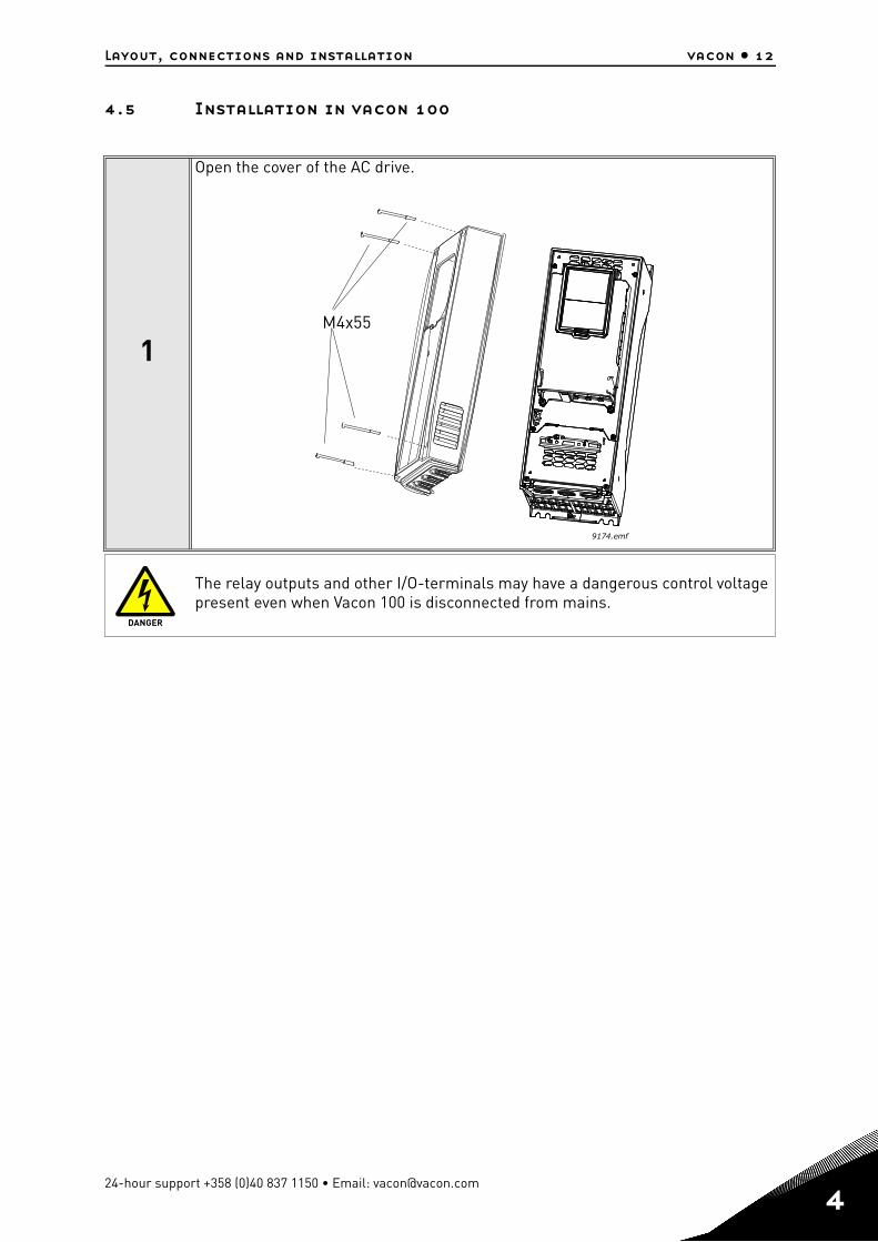
4.5 Installation in vacon 100
1
Open the cover of the AC drive.
The relay outputs and other I/O-terminals may have a dangerous control voltage present even when Vacon 100 is disconnected from mains.
M4x55
9174.emf
DANGER
24-hour support +358 (0)40 837 1150 • Email: [email protected]
4
4
vacon • 13 Layout, connections and installation
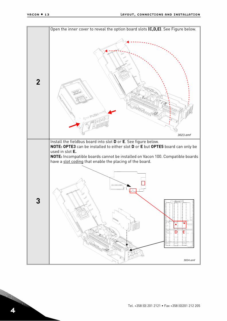
2
Open the inner cover to reveal the option board slots (C,D,E). See Figure below.
3
Install the fieldbus board into slot D or E. See figure below.NOTE: OPTE3 can be installed to either slot D or E but OPTE5 board can only be used in slot E.NOTE: Incompatible boards cannot be installed on Vacon 100. Compatible boards have a slot coding that enable the placing of the board.
3023.emf
D E
3024.emf
Tel. +358 (0) 201 2121 • Fax +358 (0)201 212 205
Layout, connections and installation vacon • 14
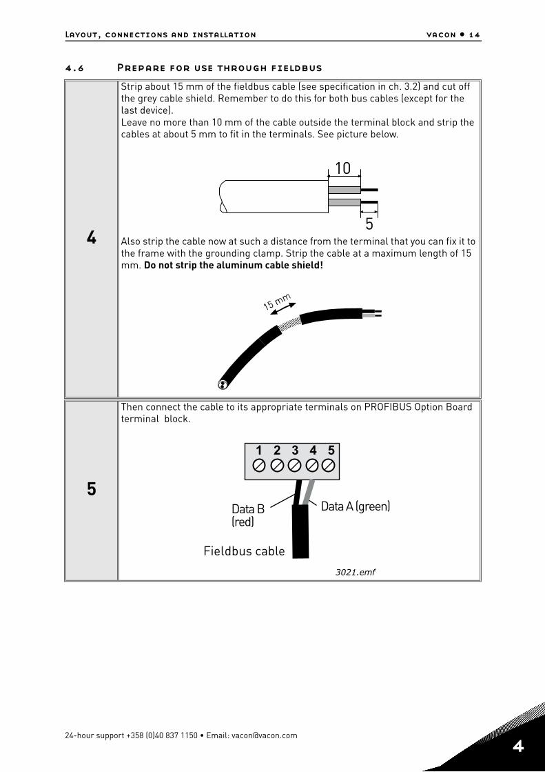
4.6 Prepare for use through fieldbus
4
Strip about 15 mm of the fieldbus cable (see specification in ch. 3.2) and cut off the grey cable shield. Remember to do this for both bus cables (except for the last device).Leave no more than 10 mm of the cable outside the terminal block and strip the cables at about 5 mm to fit in the terminals. See picture below.
Also strip the cable now at such a distance from the terminal that you can fix it to the frame with the grounding clamp. Strip the cable at a maximum length of 15 mm. Do not strip the aluminum cable shield!
5
Then connect the cable to its appropriate terminals on PROFIBUS Option Board terminal block.
10
5
1 2 3 4 5
Fieldbus cable
Data A (green)Data B(red)
3021.emf
24-hour support +358 (0)40 837 1150 • Email: [email protected]
4
4
vacon • 15 Layout, connections and installation
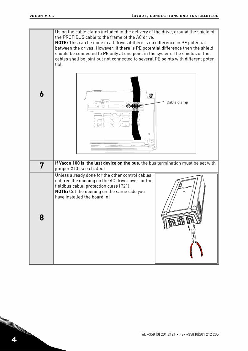
6
Using the cable clamp included in the delivery of the drive, ground the shield of the PROFIBUS cable to the frame of the AC drive.NOTE: This can be done in all drives if there is no difference in PE potential between the drives. However, if there is PE potential difference then the shield should be connected to PE only at one point in the system. The shields of the cables shall be joint but not connected to several PE points with different poten-tial.
7 If Vacon 100 is the last device on the bus, the bus termination must be set with jumper X13 (see ch. 4.4.)
8
Unless already done for the other control cables, cut free the opening on the AC drive cover for the fieldbus cable (protection class IP21). NOTE: Cut the opening on the same side you have installed the board in!
Cable clamp
Tel. +358 (0) 201 2121 • Fax +358 (0)201 212 205
Layout, connections and installation vacon • 16
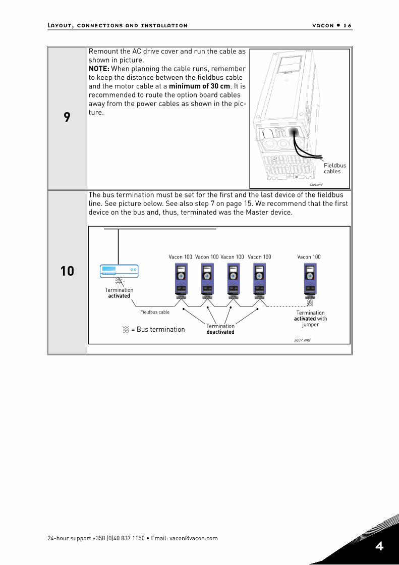
9
Remount the AC drive cover and run the cable as shown in picture.NOTE: When planning the cable runs, remember to keep the distance between the fieldbus cable and the motor cable at a minimum of 30 cm. It is recommended to route the option board cables away from the power cables as shown in the pic-ture.
10
The bus termination must be set for the first and the last device of the fieldbus line. See picture below. See also step 7 on page 15. We recommend that the first device on the bus and, thus, terminated was the Master device.
9202.emf
Fieldbuscables
Fieldbus cable
= Bus termination
Terminationactivated
Terminationactivated with
jumperTerminationdeactivated
Vacon 100 Vacon 100 Vacon 100 Vacon 100 Vacon 100
3007.emf
24-hour support +358 (0)40 837 1150 • Email: [email protected]
4

5
vacon • 18 Commissioning
5. COMMISSIONING
5.1 PROFIBUS DP board parameters
5.1.1 Parameter descriptions
Slave address: Valid PROFIBUS device addresses are in the range of 0 to 127 (decimal). The address 0 is reserved for Service-, diagnosis- and programming tools. Address 1 is reserved for the fieldbus master. Address 127 is a broadcast address. Address 126 is only for commis-sioning and should not be used permantently. Thus, values in the range from 2 to 125 can be assigned to individual slave devices.
Operate mode: 3 different operate modes are available in OPTE5/3 (see figures below). The PROFIdrive mode uses telegrams specified in the profile specification. Bypass mode uses manufacturer-specific CW, SW & PD1-PD8. Echo mode echoes the data back to the fieldbus master.
Code Parameter Min Max Unit Default ID Description
M5.x.3.1 Slave address 2 126 126 Address of the slave
M5.x.3.2 Operate mode 1 3 11 = Profidrive2 = Bypass3 = Echo
Tel. +358 (0) 201 2121 • Fax +358 (0)201 212 205
Commissioning vacon • 19
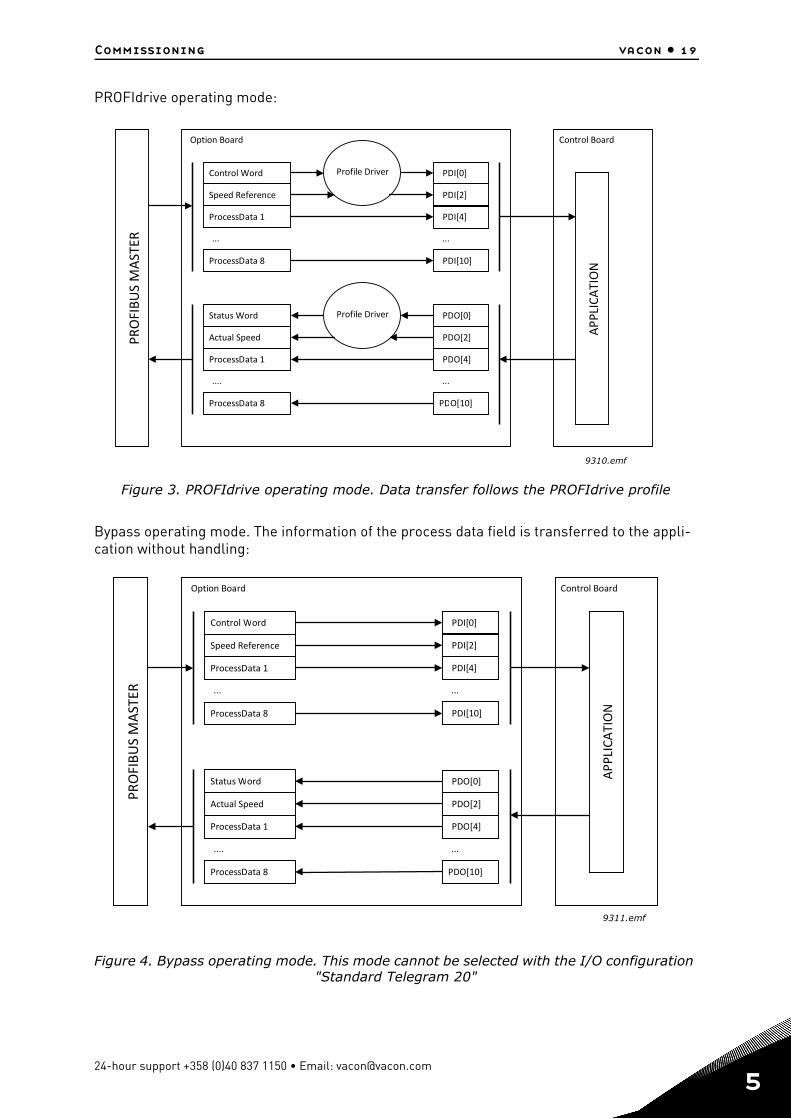
PROFIdrive operating mode:
Figure 3. PROFIdrive operating mode. Data transfer follows the PROFIdrive profile
Bypass operating mode. The information of the process data field is transferred to the appli-cation without handling:
Figure 4. Bypass operating mode. This mode cannot be selected with the I/O configuration "Standard Telegram 20"
PROFIBUSMASTER
Option Board
Control Word
Speed Reference
ProcessData 1
...
ProcessData 8
Status Word
Actual Speed
ProcessData 1
....
ProcessData 8
Profile Driver
Profile Driver
PDI[0]
PDI[2]
PDI[4]
...
PDI[10]
PDO[0]
PDO[2]
PDO[4]
...
PDO[10]
Control Board
APPLICATION
9310.emf
PROFIBUSMASTER
Option Board
Control Word
Speed Reference
ProcessData 1
ProcessData 8
...
Status Word
Actual Speed
ProcessData 1
....
ProcessData 8
PDI[0]
PDI[2]
PDI[4]
...
PDI[10]
PDO[0]
PDO[2]
PDO[4]
...
PDO[10]
APPLICATION
Control Board
9311.emf
24-hour support +358 (0)40 837 1150 • Email: [email protected]
5
5
vacon • 20 Commissioning
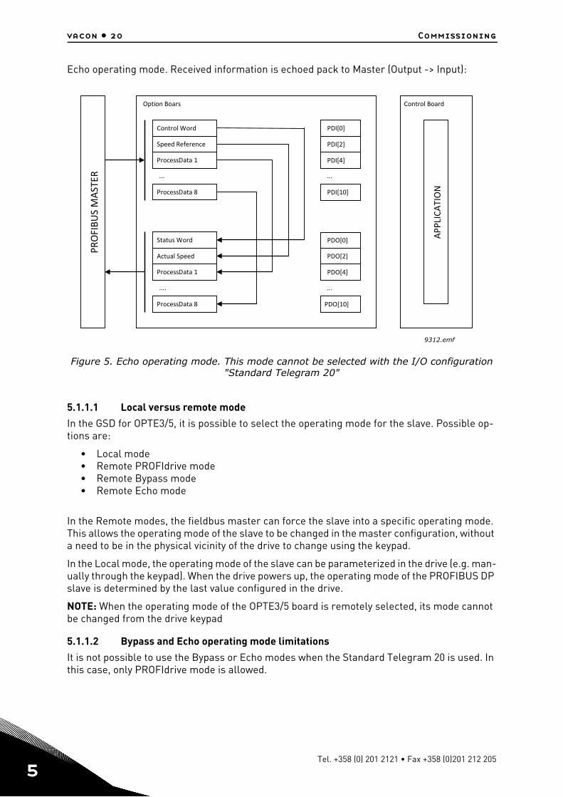
Echo operating mode. Received information is echoed pack to Master (Output -> Input):
Figure 5. Echo operating mode. This mode cannot be selected with the I/O configuration "Standard Telegram 20"
5.1.1.1 Local versus remote mode
In the GSD for OPTE3/5, it is possible to select the operating mode for the slave. Possible op-tions are:
• Local mode• Remote PROFIdrive mode• Remote Bypass mode• Remote Echo mode
In the Remote modes, the fieldbus master can force the slave into a specific operating mode. This allows the operating mode of the slave to be changed in the master configuration, without a need to be in the physical vicinity of the drive to change using the keypad.
In the Local mode, the operating mode of the slave can be parameterized in the drive (e.g. man-ually through the keypad). When the drive powers up, the operating mode of the PROFIBUS DP slave is determined by the last value configured in the drive.
NOTE: When the operating mode of the OPTE3/5 board is remotely selected, its mode cannot be changed from the drive keypad
5.1.1.2 Bypass and Echo operating mode limitations
It is not possible to use the Bypass or Echo modes when the Standard Telegram 20 is used. In this case, only PROFIdrive mode is allowed.
PROFIBUSMASTER
Control Word
Speed Reference
ProcessData 1
ProcessData 8
...
Option Boars
Status Word
Actual Speed
ProcessData 1
....
ProcessData 8
PDI[0]
PDI[2]
PDI[4]
...
PDI[10]
PDO[0]
PDO[2]
PDO[4]
...
PDO[10]
APPLICATION
Control Board
9312.emf
Tel. +358 (0) 201 2121 • Fax +358 (0)201 212 205
PROFIBUS DP interface vacon • 21
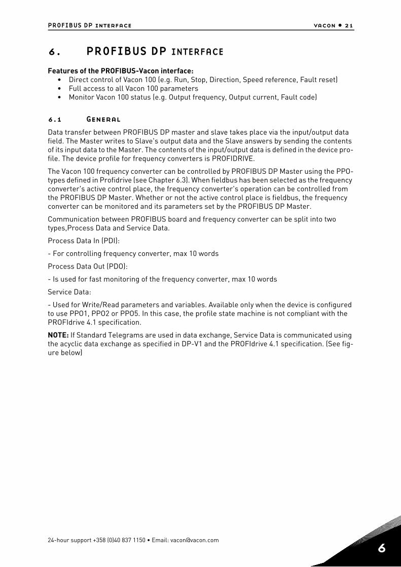
6. PROFIBUS DP INTERFACE
Features of the PROFIBUS-Vacon interface:• Direct control of Vacon 100 (e.g. Run, Stop, Direction, Speed reference, Fault reset)• Full access to all Vacon 100 parameters• Monitor Vacon 100 status (e.g. Output frequency, Output current, Fault code)
6.1 General
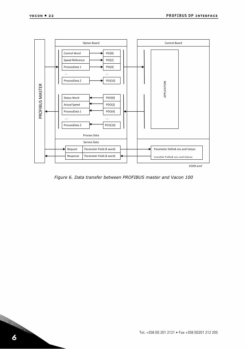
Data transfer between PROFIBUS DP master and slave takes place via the input/output data field. The Master writes to Slave's output data and the Slave answers by sending the contents of its input data to the Master. The contents of the input/output data is defined in the device pro-file. The device profile for frequency converters is PROFIDRIVE.
The Vacon 100 frequency converter can be controlled by PROFIBUS DP Master using the PPO-types defined in Profidrive (see Chapter 6.3). When fieldbus has been selected as the frequency converter's active control place, the frequency converter's operation can be controlled from the PROFIBUS DP Master. Whether or not the active control place is fieldbus, the frequency converter can be monitored and its parameters set by the PROFIBUS DP Master.
Communication between PROFIBUS board and frequency converter can be split into two types,Process Data and Service Data.
Process Data In (PDI):
- For controlling frequency converter, max 10 words
Process Data Out (PDO):
- Is used for fast monitoring of the frequency converter, max 10 words
Service Data:
- Used for Write/Read parameters and variables. Available only when the device is configured to use PPO1, PPO2 or PPO5. In this case, the profile state machine is not compliant with the PROFIdrive 4.1 specification.
NOTE: If Standard Telegrams are used in data exchange, Service Data is communicated using the acyclic data exchange as specified in DP-V1 and the PROFIdrive 4.1 specification. (See fig-ure below)
24-hour support +358 (0)40 837 1150 • Email: [email protected]
6
6
vacon • 22 PROFIBUS DP interface
Figure 6. Data transfer between PROFIBUS master and Vacon 100
PROFIBUSMASTER
Control Word
Speed Reference
ProcessData 1
...
ProcessData 2
Status Word
Actual Speed
ProcessData 1
....
ProcessData 2
PDI[0]
PDI[2]
PDI[4]
...
PDI[10]
PDO[0]
PDO[2]
PDO[4]
...
PDO[10]
Option Board Control Board
Service Data
Parameter Field (4 word)
Parameter Field (4 word)
Request
Response
Parameter Definiti ons and Values
Variable Definiti ons and Values
Process Data
APPLICATION
9309.emf
Tel. +358 (0) 201 2121 • Fax +358 (0)201 212 205
PROFIBUS DP interface vacon • 23
6.2 Data mapping for PROFIdrive 4.1
This section describes the messages used for controlling the drive through the OPTE5/OPTE3 PROFIBUS DP option board.
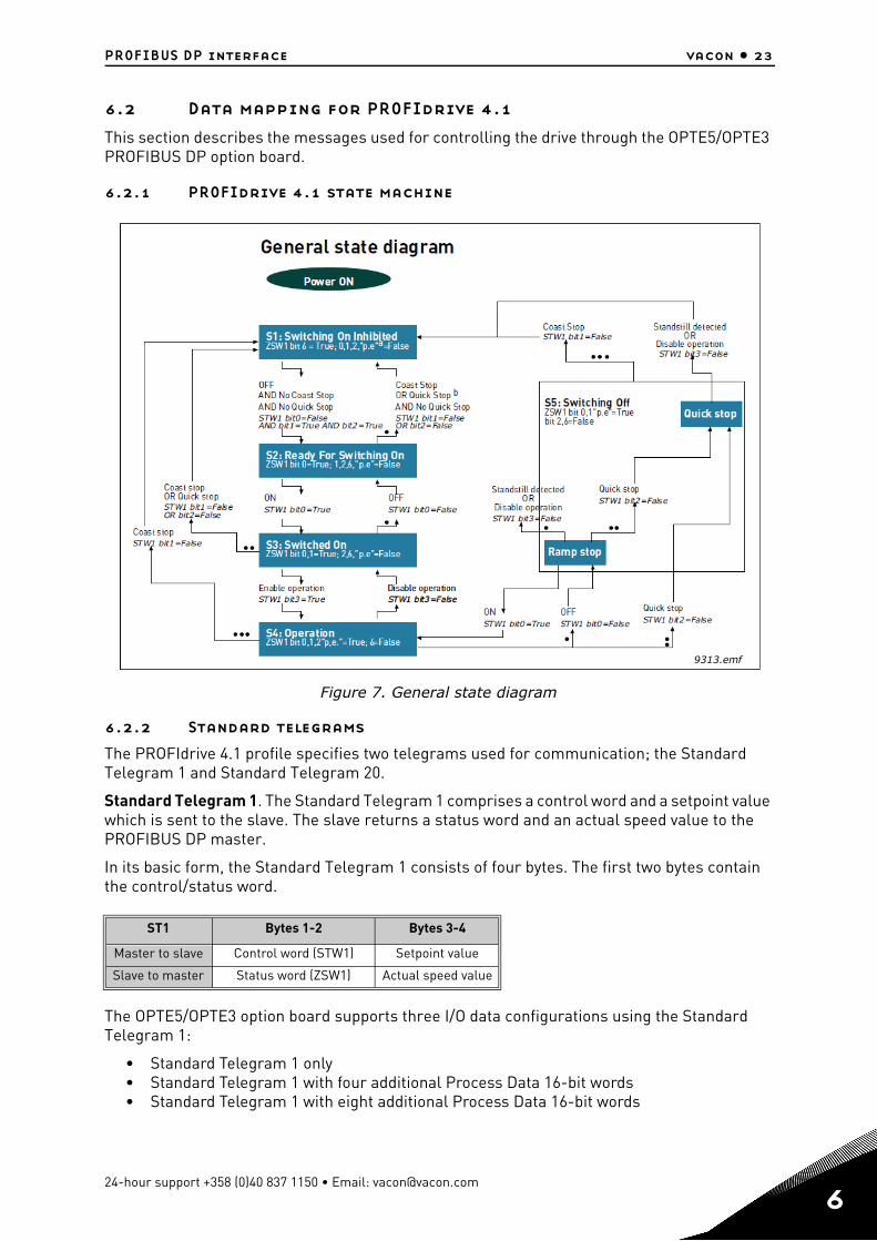
6.2.1 PROFIdrive 4.1 state machine
Figure 7. General state diagram
6.2.2 Standard telegrams
The PROFIdrive 4.1 profile specifies two telegrams used for communication; the Standard Telegram 1 and Standard Telegram 20.
Standard Telegram 1. The Standard Telegram 1 comprises a control word and a setpoint value which is sent to the slave. The slave returns a status word and an actual speed value to the PROFIBUS DP master.
In its basic form, the Standard Telegram 1 consists of four bytes. The first two bytes contain the control/status word.
The OPTE5/OPTE3 option board supports three I/O data configurations using the Standard Telegram 1:
• Standard Telegram 1 only• Standard Telegram 1 with four additional Process Data 16-bit words• Standard Telegram 1 with eight additional Process Data 16-bit words
ST1 Bytes 1-2 Bytes 3-4
Master to slave Control word (STW1) Setpoint value
Slave to master Status word (ZSW1) Actual speed value
9313.emf
24-hour support +358 (0)40 837 1150 • Email: [email protected]
6
6
vacon • 24 PROFIBUS DP interface
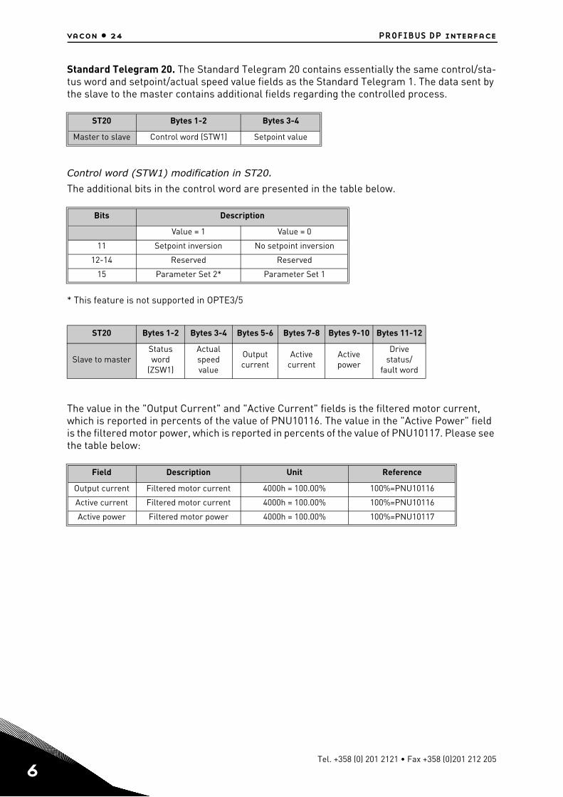
Standard Telegram 20. The Standard Telegram 20 contains essentially the same control/sta-tus word and setpoint/actual speed value fields as the Standard Telegram 1. The data sent by the slave to the master contains additional fields regarding the controlled process.
Control word (STW1) modification in ST20.
The additional bits in the control word are presented in the table below.
* This feature is not supported in OPTE3/5
The value in the "Output Current" and "Active Current" fields is the filtered motor current, which is reported in percents of the value of PNU10116. The value in the "Active Power" field is the filtered motor power, which is reported in percents of the value of PNU10117. Please see the table below:
ST20 Bytes 1-2 Bytes 3-4
Master to slave Control word (STW1) Setpoint value
Bits Description
Value = 1 Value = 0
11 Setpoint inversion No setpoint inversion
12-14 Reserved Reserved
15 Parameter Set 2* Parameter Set 1
ST20 Bytes 1-2 Bytes 3-4 Bytes 5-6 Bytes 7-8 Bytes 9-10 Bytes 11-12
Slave to masterStatusword
(ZSW1)
Actualspeedvalue
Outputcurrent
Activecurrent
Activepower
Drive status/
fault word
Field Description Unit Reference
Output current Filtered motor current 4000h = 100.00% 100%=PNU10116
Active current Filtered motor current 4000h = 100.00% 100%=PNU10116
Active power Filtered motor power 4000h = 100.00% 100%=PNU10117
Tel. +358 (0) 201 2121 • Fax +358 (0)201 212 205
PROFIBUS DP interface vacon • 25
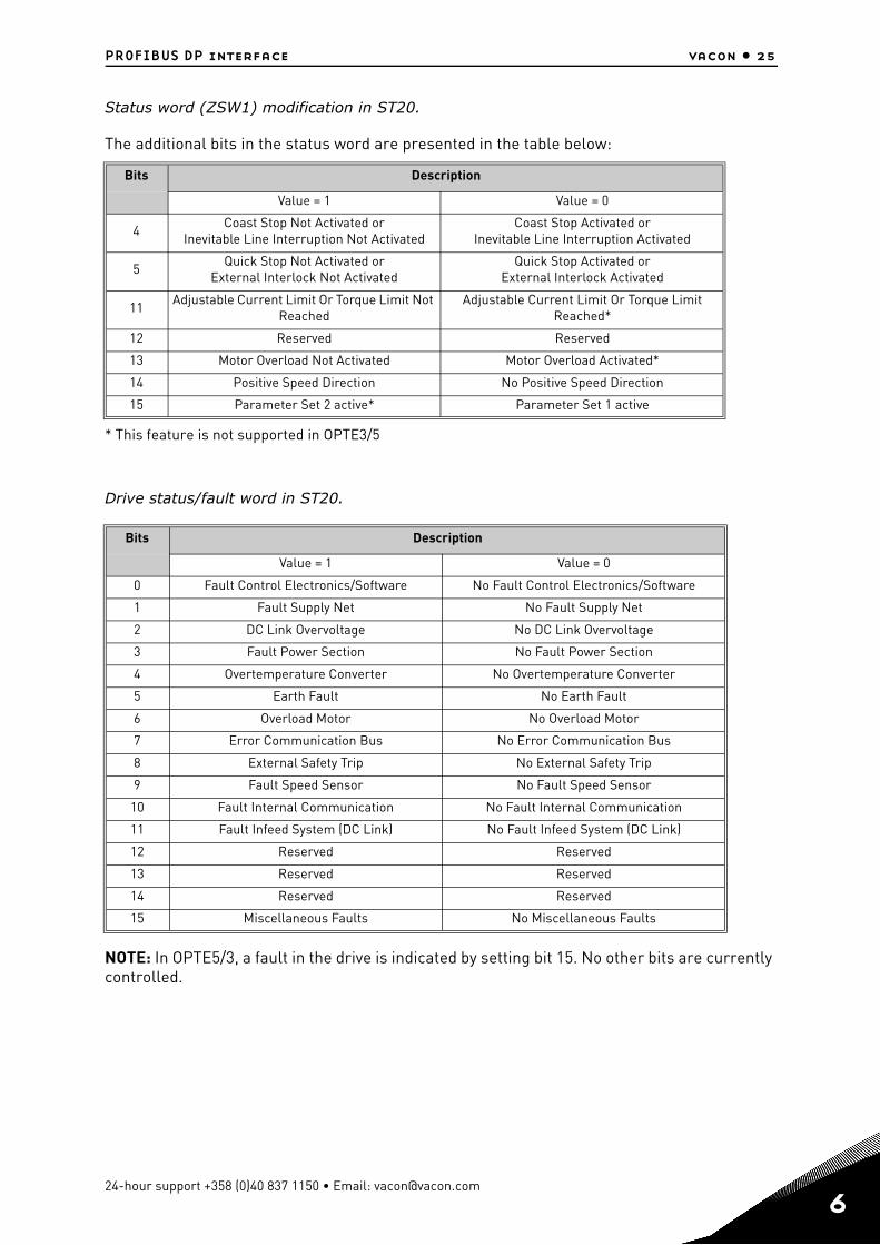
Status word (ZSW1) modification in ST20.
The additional bits in the status word are presented in the table below:
* This feature is not supported in OPTE3/5
Drive status/fault word in ST20.
NOTE: In OPTE5/3, a fault in the drive is indicated by setting bit 15. No other bits are currently controlled.
Bits Description
Value = 1 Value = 0
4Coast Stop Not Activated or
Inevitable Line Interruption Not ActivatedCoast Stop Activated or
Inevitable Line Interruption Activated
5Quick Stop Not Activated or
External Interlock Not ActivatedQuick Stop Activated or
External Interlock Activated
11Adjustable Current Limit Or Torque Limit Not
ReachedAdjustable Current Limit Or Torque Limit
Reached*
12 Reserved Reserved
13 Motor Overload Not Activated Motor Overload Activated*
14 Positive Speed Direction No Positive Speed Direction
15 Parameter Set 2 active* Parameter Set 1 active
Bits Description
Value = 1 Value = 0
0 Fault Control Electronics/Software No Fault Control Electronics/Software
1 Fault Supply Net No Fault Supply Net
2 DC Link Overvoltage No DC Link Overvoltage
3 Fault Power Section No Fault Power Section
4 Overtemperature Converter No Overtemperature Converter
5 Earth Fault No Earth Fault
6 Overload Motor No Overload Motor
7 Error Communication Bus No Error Communication Bus
8 External Safety Trip No External Safety Trip
9 Fault Speed Sensor No Fault Speed Sensor
10 Fault Internal Communication No Fault Internal Communication
11 Fault Infeed System (DC Link) No Fault Infeed System (DC Link)
12 Reserved Reserved
13 Reserved Reserved
14 Reserved Reserved
15 Miscellaneous Faults No Miscellaneous Faults
24-hour support +358 (0)40 837 1150 • Email: [email protected]
6
6
vacon • 26 PROFIBUS DP interface
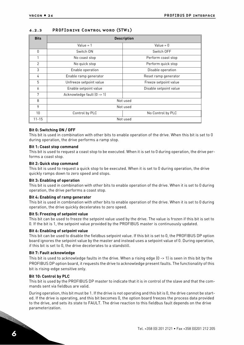
6.2.3 PROFIdrive Control word (STW1)
Bit 0: Switching ON / OFFThis bit is used in combination with other bits to enable operation of the drive. When this bit is set to 0 during operation, the drive performs a ramp stop.
Bit 1: Coast stop commandThis bit is used to request a coast stop to be executed. When it is set to 0 during operation, the drive per-forms a coast stop.
Bit 2: Quick stop commandThis bit is used to request a quick stop to be executed. When it is set to 0 during operation, the drive quickly ramps down to zero speed and stops.
Bit 3: Enabling of operationThis bit is used in combination with other bits to enable operation of the drive. When it is set to 0 during operation, the drive performs a coast stop.
Bit 4: Enabling of ramp generatorThis bit is used in combination with other bits to enable operation of the drive. When it is set to 0 during operation, the drive quickly decelerates to zero speed.
Bit 5: Freezing of setpoint valueThis bit can be used to freeze the setpoint value used by the drive. The value is frozen if this bit is set to 0. If the bit is 1, the setpoint value provided by the PROFIBUS master is continuously updated.
Bit 6: Enabling of setpoint valueThis bit can be used to disable the fieldbus setpoint value. If this bit is set to 0, the PROFIBUS DP option board ignores the setpoint value by the master and instead uses a setpoint value of 0. During operation, if this bit is set to 0, the drive decelerates to a standstill.
Bit 7: Fault acknowledgeThis bit is used to acknowledge faults in the drive. When a rising edge (0 -> 1) is seen in this bit by the PROFIBUS DP option board, it requests the drive to acknowledge present faults. The functionality of this bit is rising-edge sensitive only.
Bit 10: Control by PLCThis bit is used by the PROFIBUS DP master to indicate that it is in control of the slave and that the com-mands sent via fieldbus are valid.
During operation, this bit must be 1. If the drive is not operating and this bit is 0, the drive cannot be start-ed. If the drive is operating, and this bit becomes 0, the option board freezes the process data provided to the drive, and sets its state to FAULT. The drive reaction to this fieldbus fault depends on the drive parameterization.
Bits Description
Value = 1 Value = 0
0 Switch ON Switch OFF
1 No coast stop Perform coast stop
2 No quick stop Perform quick stop
3 Enable operation Disable operation
4 Enable ramp generator Reset ramp generator
5 Unfreeze setpoint value Freeze setpoint value
6 Enable setpoint value Disable setpoint value
7 Acknowledge fault (0 -> 1)
8 Not used
9 Not used
10 Control by PLC No Control by PLC
11-15 Not used
Tel. +358 (0) 201 2121 • Fax +358 (0)201 212 205
PROFIBUS DP interface vacon • 27
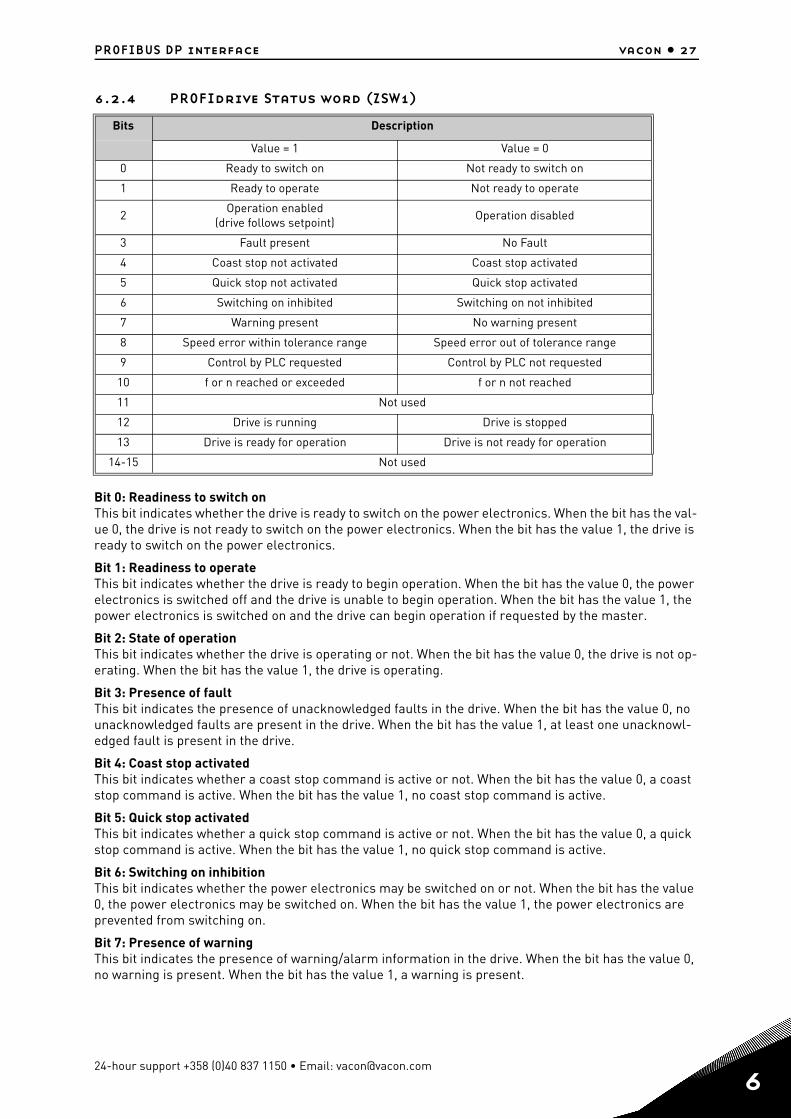
6.2.4 PROFIdrive Status word (ZSW1)
Bit 0: Readiness to switch onThis bit indicates whether the drive is ready to switch on the power electronics. When the bit has the val-ue 0, the drive is not ready to switch on the power electronics. When the bit has the value 1, the drive is ready to switch on the power electronics.
Bit 1: Readiness to operateThis bit indicates whether the drive is ready to begin operation. When the bit has the value 0, the power electronics is switched off and the drive is unable to begin operation. When the bit has the value 1, the power electronics is switched on and the drive can begin operation if requested by the master.
Bit 2: State of operationThis bit indicates whether the drive is operating or not. When the bit has the value 0, the drive is not op-erating. When the bit has the value 1, the drive is operating.
Bit 3: Presence of faultThis bit indicates the presence of unacknowledged faults in the drive. When the bit has the value 0, no unacknowledged faults are present in the drive. When the bit has the value 1, at least one unacknowl-edged fault is present in the drive.
Bit 4: Coast stop activatedThis bit indicates whether a coast stop command is active or not. When the bit has the value 0, a coast stop command is active. When the bit has the value 1, no coast stop command is active.
Bit 5: Quick stop activatedThis bit indicates whether a quick stop command is active or not. When the bit has the value 0, a quick stop command is active. When the bit has the value 1, no quick stop command is active.
Bit 6: Switching on inhibitionThis bit indicates whether the power electronics may be switched on or not. When the bit has the value 0, the power electronics may be switched on. When the bit has the value 1, the power electronics are prevented from switching on.
Bit 7: Presence of warningThis bit indicates the presence of warning/alarm information in the drive. When the bit has the value 0, no warning is present. When the bit has the value 1, a warning is present.
Bits Description
Value = 1 Value = 0
0 Ready to switch on Not ready to switch on
1 Ready to operate Not ready to operate
2Operation enabled
(drive follows setpoint)Operation disabled
3 Fault present No Fault
4 Coast stop not activated Coast stop activated
5 Quick stop not activated Quick stop activated
6 Switching on inhibited Switching on not inhibited
7 Warning present No warning present
8 Speed error within tolerance range Speed error out of tolerance range
9 Control by PLC requested Control by PLC not requested
10 f or n reached or exceeded f or n not reached
11 Not used
12 Drive is running Drive is stopped
13 Drive is ready for operation Drive is not ready for operation
14-15 Not used
24-hour support +358 (0)40 837 1150 • Email: [email protected]
6
6
vacon • 28 PROFIBUS DP interface
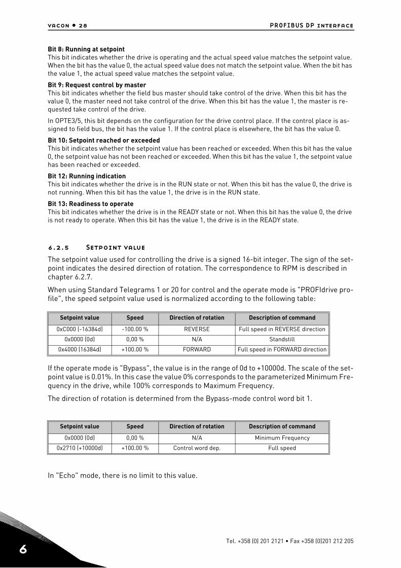
Bit 8: Running at setpointThis bit indicates whether the drive is operating and the actual speed value matches the setpoint value. When the bit has the value 0, the actual speed value does not match the setpoint value. When the bit has the value 1, the actual speed value matches the setpoint value.
Bit 9: Request control by masterThis bit indicates whether the field bus master should take control of the drive. When this bit has the value 0, the master need not take control of the drive. When this bit has the value 1, the master is re-quested take control of the drive.
In OPTE3/5, this bit depends on the configuration for the drive control place. If the control place is as-signed to field bus, the bit has the value 1. If the control place is elsewhere, the bit has the value 0.
Bit 10: Setpoint reached or exceededThis bit indicates whether the setpoint value has been reached or exceeded. When this bit has the value 0, the setpoint value has not been reached or exceeded. When this bit has the value 1, the setpoint value has been reached or exceeded.
Bit 12: Running indicationThis bit indicates whether the drive is in the RUN state or not. When this bit has the value 0, the drive is not running. When this bit has the value 1, the drive is in the RUN state.
Bit 13: Readiness to operateThis bit indicates whether the drive is in the READY state or not. When this bit has the value 0, the drive is not ready to operate. When this bit has the value 1, the drive is in the READY state.
6.2.5 Setpoint value
The setpoint value used for controlling the drive is a signed 16-bit integer. The sign of the set-point indicates the desired direction of rotation. The correspondence to RPM is described in chapter 6.2.7.
When using Standard Telegrams 1 or 20 for control and the operate mode is "PROFIdrive pro-file", the speed setpoint value used is normalized according to the following table:
If the operate mode is "Bypass", the value is in the range of 0d to +10000d. The scale of the set-point value is 0.01%. In this case the value 0% corresponds to the parameterized Minimum Fre-quency in the drive, while 100% corresponds to Maximum Frequency.
The direction of rotation is determined from the Bypass-mode control word bit 1.
In "Echo" mode, there is no limit to this value.
Setpoint value Speed Direction of rotation Description of command
0xC000 (-16384d) -100.00 % REVERSE Full speed in REVERSE direction
0x0000 (0d) 0,00 % N/A Standstill
0x4000 (16384d) +100.00 % FORWARD Full speed in FORWARD direction
Setpoint value Speed Direction of rotation Description of command
0x0000 (0d) 0,00 % N/A Minimum Frequency
0x2710 (+10000d) +100.00 % Control word dep. Full speed
Tel. +358 (0) 201 2121 • Fax +358 (0)201 212 205
PROFIBUS DP interface vacon • 29
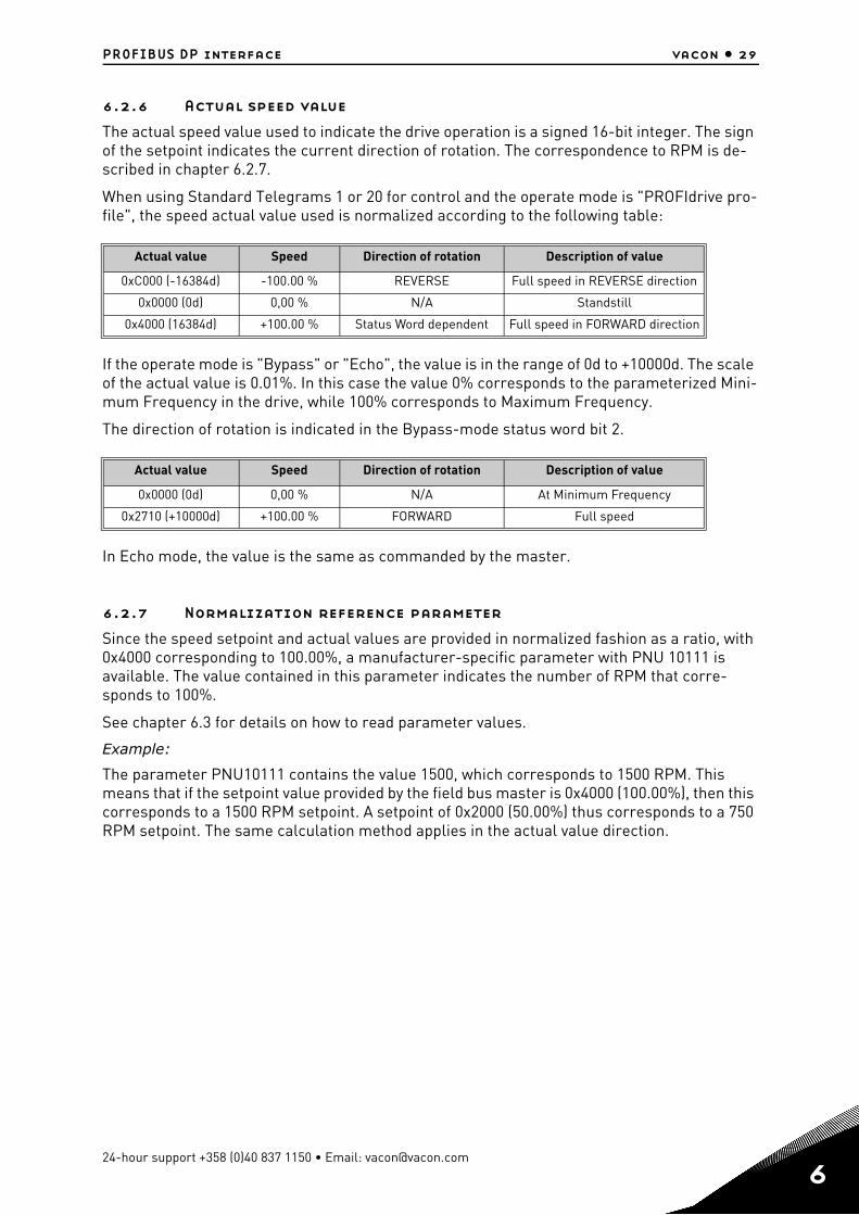
6.2.6 Actual speed value
The actual speed value used to indicate the drive operation is a signed 16-bit integer. The sign of the setpoint indicates the current direction of rotation. The correspondence to RPM is de-scribed in chapter 6.2.7.
When using Standard Telegrams 1 or 20 for control and the operate mode is "PROFIdrive pro-file", the speed actual value used is normalized according to the following table:
If the operate mode is "Bypass" or "Echo", the value is in the range of 0d to +10000d. The scale of the actual value is 0.01%. In this case the value 0% corresponds to the parameterized Mini-mum Frequency in the drive, while 100% corresponds to Maximum Frequency.
The direction of rotation is indicated in the Bypass-mode status word bit 2.
In Echo mode, the value is the same as commanded by the master.
6.2.7 Normalization reference parameter
Since the speed setpoint and actual values are provided in normalized fashion as a ratio, with 0x4000 corresponding to 100.00%, a manufacturer-specific parameter with PNU 10111 is available. The value contained in this parameter indicates the number of RPM that corre-sponds to 100%.
See chapter 6.3 for details on how to read parameter values.
Example:
The parameter PNU10111 contains the value 1500, which corresponds to 1500 RPM. This means that if the setpoint value provided by the field bus master is 0x4000 (100.00%), then this corresponds to a 1500 RPM setpoint. A setpoint of 0x2000 (50.00%) thus corresponds to a 750 RPM setpoint. The same calculation method applies in the actual value direction.
Actual value Speed Direction of rotation Description of value
0xC000 (-16384d) -100.00 % REVERSE Full speed in REVERSE direction
0x0000 (0d) 0,00 % N/A Standstill
0x4000 (16384d) +100.00 % Status Word dependent Full speed in FORWARD direction
Actual value Speed Direction of rotation Description of value
0x0000 (0d) 0,00 % N/A At Minimum Frequency
0x2710 (+10000d) +100.00 % FORWARD Full speed
24-hour support +358 (0)40 837 1150 • Email: [email protected]
6
6
vacon • 30 PROFIBUS DP interface
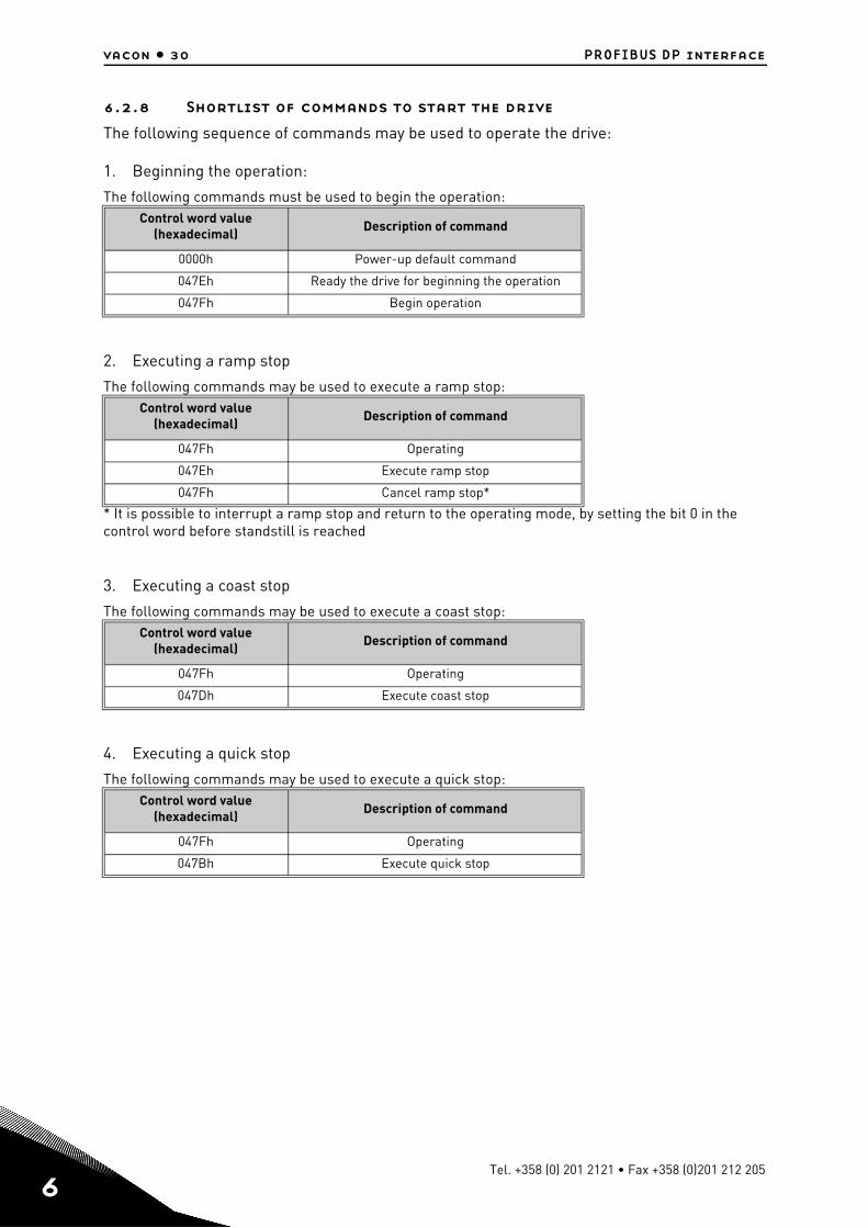
6.2.8 Shortlist of commands to start the drive
The following sequence of commands may be used to operate the drive:
1. Beginning the operation:
The following commands must be used to begin the operation:
2. Executing a ramp stop
The following commands may be used to execute a ramp stop:
* It is possible to interrupt a ramp stop and return to the operating mode, by setting the bit 0 in the control word before standstill is reached
3. Executing a coast stop
The following commands may be used to execute a coast stop:
4. Executing a quick stop
The following commands may be used to execute a quick stop:
Control word value(hexadecimal) Description of command
0000h Power-up default command
047Eh Ready the drive for beginning the operation
047Fh Begin operation
Control word value(hexadecimal)
Description of command
047Fh Operating
047Eh Execute ramp stop
047Fh Cancel ramp stop*
Control word value(hexadecimal)
Description of command
047Fh Operating
047Dh Execute coast stop
Control word value(hexadecimal)
Description of command
047Fh Operating
047Bh Execute quick stop
Tel. +358 (0) 201 2121 • Fax +358 (0)201 212 205
PROFIBUS DP interface vacon • 31
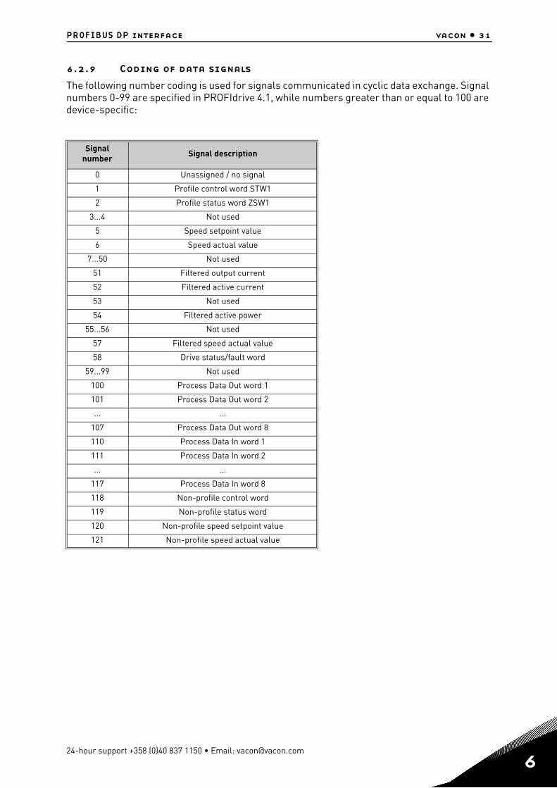
6.2.9 Coding of data signals
The following number coding is used for signals communicated in cyclic data exchange. Signal numbers 0-99 are specified in PROFIdrive 4.1, while numbers greater than or equal to 100 are device-specific:
Signal number Signal description
0 Unassigned / no signal
1 Profile control word STW1
2 Profile status word ZSW1
3...4 Not used
5 Speed setpoint value
6 Speed actual value
7...50 Not used
51 Filtered output current
52 Filtered active current
53 Not used
54 Filtered active power
55...56 Not used
57 Filtered speed actual value
58 Drive status/fault word
59...99 Not used
100 Process Data Out word 1
101 Process Data Out word 2
... ...
107 Process Data Out word 8
110 Process Data In word 1
111 Process Data In word 2
... ...
117 Process Data In word 8
118 Non-profile control word
119 Non-profile status word
120 Non-profile speed setpoint value
121 Non-profile speed actual value
24-hour support +358 (0)40 837 1150 • Email: [email protected]
6
6
vacon • 32 PROFIBUS DP interface
6.3 Parameter Access in PROFIdrive 4.1
6.3.1 Parameter Access sequence
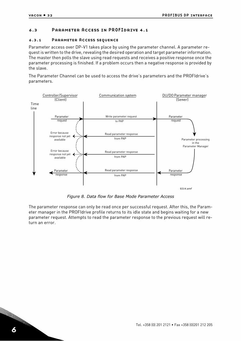
Parameter access over DP-V1 takes place by using the parameter channel. A parameter re-quest is written to the drive, revealing the desired operation and target parameter information. The master then polls the slave using read requests and receives a positive response once the parameter processing is finished. If a problem occurs then a negative response is provided by the slave.
The Parameter Channel can be used to access the drive’s parameters and the PROFIdrive’s parameters.
Figure 8. Data flow for Base Mode Parameter Access
The parameter response can only be read once per successful request. After this, the Param-eter manager in the PROFIdrive profile returns to its idle state and begins waiting for a new parameter request. Attempts to read the parameter response to the previous request will re-turn an error.
Controller/Supervisor (Client)
Communication system DU/DO Parameter manager (Server)
Timeline
Write parameter request
Read parameter response
Read parameter response
Read parameter response
to PAP
from PAP
from PAP
from PAP
9314.emf
Parameterrequest
Error becauseresponse not yet
available
Error becauseresponse not yet
available
Parameterresponse
Parameter processingin the
Parameter Manager
Parameterrequest
Parameterresponse
Tel. +358 (0) 201 2121 • Fax +358 (0)201 212 205
PROFIBUS DP interface vacon • 33
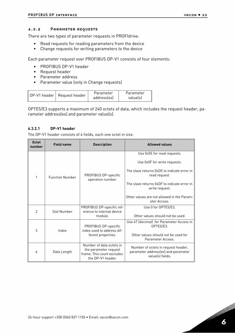
6.3.2 Parameter requests
There are two types of parameter requests in PROFIdrive:
• Read requests for reading parameters from the device• Change requests for writing parameters to the device
Each parameter request over PROFIBUS DP-V1 consists of four elements:
• PROFIBUS DP-V1 header• Request header• Parameter address• Parameter value (only in Change requests)
OPTE5/E3 supports a maximum of 240 octets of data, which includes the request header, pa-rameter address(es) and parameter value(s).
6.3.2.1 DP-V1 headerThe DP-V1 header consists of 4 fields, each one octet in size.
DP-V1 header Request header Parameter address(es)
Parameter value(s)
Octet number Field name Description Allowed values
1 Function NumberPROFIBUS DP-specific
operation number.
Use 0x5E for read requests.
Use 0x5F for write requests.
The slave returns 0xDE to indicate error in read request.
The slave returns 0xDF to indicate error in write request.
Other values are not allowed in the Param-eter Access.
2 Slot NumberPROFIBUS DP-specific ref-
erence to internal device module.
Use 0 for OPTE5/E3.
Other values should not be used.
3 IndexPROFIBUS DP-specific
index used to address dif-ferent properties.
Use 47 (decimal) for Parameter Access in OPTE5/E3.
Other values should not be used for Parameter Access.
4 Data Length
Number of data octets in the parameter request
frame. This count excludes the DP-V1 header.
Number of octets in request header, parameter address(es) and parameter
value(s) fields.
24-hour support +358 (0)40 837 1150 • Email: [email protected]
6
6
vacon • 34 PROFIBUS DP interface
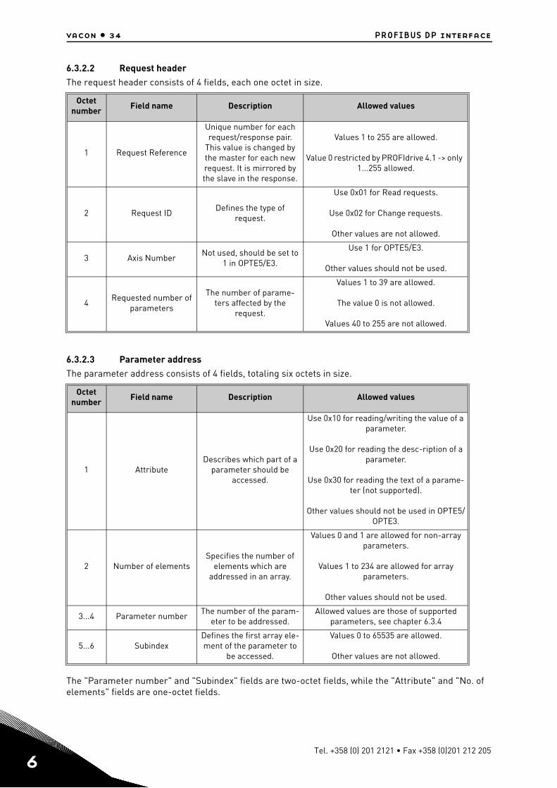
6.3.2.2 Request headerThe request header consists of 4 fields, each one octet in size.
6.3.2.3 Parameter addressThe parameter address consists of 4 fields, totaling six octets in size.
The "Parameter number" and "Subindex" fields are two-octet fields, while the "Attribute" and "No. of elements" fields are one-octet fields.
Octet number Field name Description Allowed values
1 Request Reference
Unique number for each request/response pair.
This value is changed by the master for each new request. It is mirrored by the slave in the response.
Values 1 to 255 are allowed.
Value 0 restricted by PROFIdrive 4.1 -> only 1...255 allowed.
2 Request IDDefines the type of
request.
Use 0x01 for Read requests.
Use 0x02 for Change requests.
Other values are not allowed.
3 Axis NumberNot used, should be set to
1 in OPTE5/E3.
Use 1 for OPTE5/E3.
Other values should not be used.
4Requested number of
parameters
The number of parame-ters affected by the
request.
Values 1 to 39 are allowed.
The value 0 is not allowed.
Values 40 to 255 are not allowed.
Octet number
Field name Description Allowed values
1 AttributeDescribes which part of a
parameter should be accessed.
Use 0x10 for reading/writing the value of a parameter.
Use 0x20 for reading the desc-ription of a parameter.
Use 0x30 for reading the text of a parame-ter (not supported).
Other values should not be used in OPTE5/OPTE3.
2 Number of elementsSpecifies the number of
elements which are addressed in an array.
Values 0 and 1 are allowed for non-array parameters.
Values 1 to 234 are allowed for array parameters.
Other values should not be used.
3...4 Parameter numberThe number of the param-
eter to be addressed.Allowed values are those of supported
parameters, see chapter 6.3.4
5...6 SubindexDefines the first array ele-ment of the parameter to
be accessed.
Values 0 to 65535 are allowed.
Other values are not allowed.
Tel. +358 (0) 201 2121 • Fax +358 (0)201 212 205
PROFIBUS DP interface vacon • 35
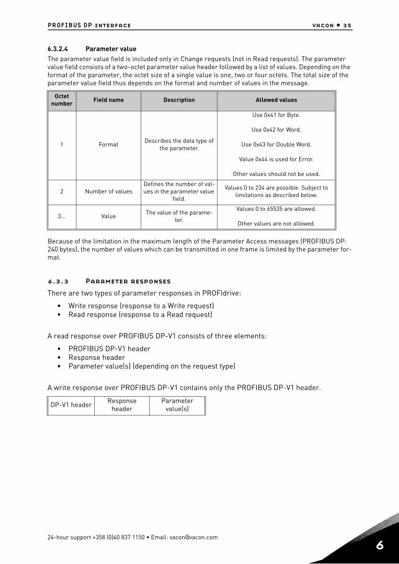
6.3.2.4 Parameter valueThe parameter value field is included only in Change requests (not in Read requests). The parameter value field consists of a two-octet parameter value header followed by a list of values. Depending on the format of the parameter, the octet size of a single value is one, two or four octets. The total size of the parameter value field thus depends on the format and number of values in the message.
Because of the limitation in the maximum length of the Parameter Access messages (PROFIBUS DP: 240 bytes), the number of values which can be transmitted in one frame is limited by the parameter for-mat.
6.3.3 Parameter responses
There are two types of parameter responses in PROFIdrive:
• Write response (response to a Write request)• Read response (response to a Read request)
A read response over PROFIBUS DP-V1 consists of three elements:
• PROFIBUS DP-V1 header• Response header• Parameter value(s) (depending on the request type)
A write response over PROFIBUS DP-V1 contains only the PROFIBUS DP-V1 header.
Octet number Field name Description Allowed values
1 FormatDescribes the data type of
the parameter.
Use 0x41 for Byte.
Use 0x42 for Word.
Use 0x43 for Double Word.
Value 0x44 is used for Error.
Other values should not be used.
2 Number of valuesDefines the number of val-ues in the parameter value
field.
Values 0 to 234 are possible. Subject to limitations as described below.
3... ValueThe value of the parame-
ter.
Values 0 to 65535 are allowed.
Other values are not allowed.
DP-V1 header Response header
Parameter value(s)
24-hour support +358 (0)40 837 1150 • Email: [email protected]
6
6
vacon • 36 PROFIBUS DP interface
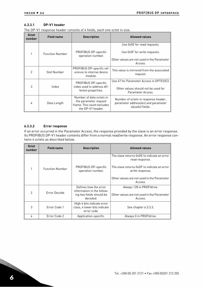
6.3.3.1 DP-V1 headerThe DP-V1 response header consists of 4 fields, each one octet in size.
6.3.3.2 Error responseIf an error occurred in the Parameter Access, the response provided by the slave is an error response. Its PROFIBUS DP-V1 header contents differ from a normal read/write response. An error response con-tains 4 octets as described below.
Octet number
Field name Description Allowed values
1 Function NumberPROFIBUS DP-specific
operation number.
Use 0x5E for read requests.
Use 0x5F for write requests.
Other values are not used in the Parameter Access.
2 Slot NumberPROFIBUS DP-specific ref-
erence to internal device module.
This value is mirrored from the associated request.
3 IndexPROFIBUS DP-specific
index used to address dif-ferent properties.
Use 47 for Parameter Access in OPTE5/E3.
Other values should not be used for Parameter Access.
4 Data Length
Number of data octets in the parameter request
frame. This count excludes the DP-V1 header.
Number of octets in response header, parameter address(es) and parameter
value(s) fields.
Octet number
Field name Description Allowed values
1 Function NumberPROFIBUS DP-specific
operation number.
The slave returns 0xDE to indicate an error read response.
The slave returns 0xDF to indicate an error write response.
Other values are not used in the Parameter Access.
2 Error Decode
Defines how the error information in the follow-ing two fields should be
decoded.
Always 128 in PROFIdrive.
Other values are not used in the Parameter Access.
3 Error Code 1High 4 bits indicate error
class, 4 lower bits indicate error code.
See chapter 6.3.3.3.
4 Error Code 2 Application-specific. Always 0 in PROFIdrive.
Tel. +358 (0) 201 2121 • Fax +358 (0)201 212 205
PROFIBUS DP interface vacon • 37
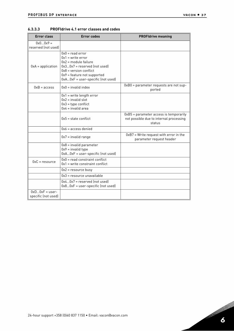
6.3.3.3 PROFIdrive 4.1 error classes and codes
Error class Error codes PROFIdrive meaning
0x0...0x9 = reserved (not used)
0xA = application
0x0 = read error0x1 = write error0x2 = module failure0x3…0x7 = reserved (not used)0x8 = version conflict0x9 = feature not supported0xA…0xF = user-specific (not used)
0xB = access 0x0 = invalid index0xB0 = parameter requests are not sup-
ported
0x1 = write length error0x2 = invalid slot0x3 = type conflict0x4 = invalid area
0x5 = state conflict0xB5 = parameter access is temporarily not possible due to internal processing
status
0x6 = access denied
0x7 = invalid range0xB7 = Write request with error in the
parameter request header
0x8 = invalid parameter0x9 = invalid type0xA…0xF = user-specific (not used)
0xC = resource0x0 = read constraint conflict0x1 = write constraint conflict
0x2 = resource busy
0x3 = resource unavailable
0x4…0x7 = reserved (not used)0x8…0xF = user-specific (not used)
0xD…0xF = user-specific (not used)
24-hour support +358 (0)40 837 1150 • Email: [email protected]
6
6
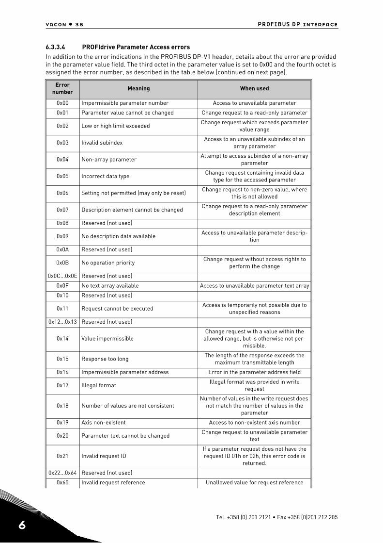
vacon • 38 PROFIBUS DP interface
6.3.3.4 PROFIdrive Parameter Access errorsIn addition to the error indications in the PROFIBUS DP-V1 header, details about the error are provided in the parameter value field. The third octet in the parameter value is set to 0x00 and the fourth octet is assigned the error number, as described in the table below (continued on next page).
Error number Meaning When used
0x00 Impermissible parameter number Access to unavailable parameter
0x01 Parameter value cannot be changed Change request to a read-only parameter
0x02 Low or high limit exceededChange request which exceeds parameter
value range
0x03 Invalid subindexAccess to an unavailable subindex of an
array parameter
0x04 Non-array parameterAttempt to access subindex of a non-array
parameter
0x05 Incorrect data typeChange request containing invalid data
type for the accessed parameter
0x06 Setting not permitted (may only be reset)Change request to non-zero value, where
this is not allowed
0x07 Description element cannot be changedChange request to a read-only parameter
description element
0x08 Reserved (not used)
0x09 No description data availableAccess to unavailable parameter descrip-
tion
0x0A Reserved (not used)
0x0B No operation priorityChange request without access rights to
perform the change
0x0C...0x0E Reserved (not used)
0x0F No text array available Access to unavailable parameter text array
0x10 Reserved (not used)
0x11 Request cannot be executedAccess is temporarily not possible due to
unspecified reasons
0x12...0x13 Reserved (not used)
0x14 Value impermissibleChange request with a value within the
allowed range, but is otherwise not per-missible.
0x15 Response too longThe length of the response exceeds the
maximum transmittable length
0x16 Impermissible parameter address Error in the parameter address field
0x17 Illegal formatIllegal format was provided in write
request
0x18 Number of values are not consistentNumber of values in the write request does
not match the number of values in the parameter
0x19 Axis non-existent Access to non-existent axis number
0x20 Parameter text cannot be changedChange request to unavailable parameter
text
0x21 Invalid request IDIf a parameter request does not have the request ID 01h or 02h, this error code is
returned.
0x22...0x64 Reserved (not used)
0x65 Invalid request reference Unallowed value for request reference
Tel. +358 (0) 201 2121 • Fax +358 (0)201 212 205
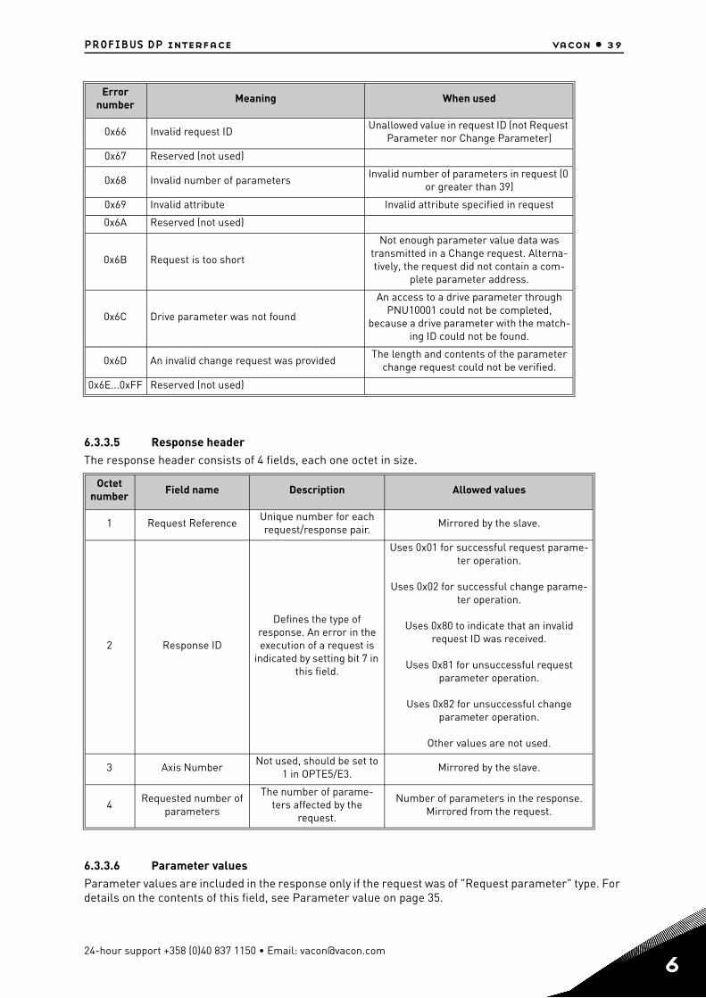
PROFIBUS DP interface vacon • 39
6.3.3.5 Response headerThe response header consists of 4 fields, each one octet in size.
6.3.3.6 Parameter valuesParameter values are included in the response only if the request was of "Request parameter" type. For details on the contents of this field, see Parameter value on page 35.
0x66 Invalid request IDUnallowed value in request ID (not Request
Parameter nor Change Parameter)
0x67 Reserved (not used)
0x68 Invalid number of parametersInvalid number of parameters in request (0
or greater than 39)
0x69 Invalid attribute Invalid attribute specified in request
0x6A Reserved (not used)
0x6B Request is too short
Not enough parameter value data was transmitted in a Change request. Alterna-tively, the request did not contain a com-
plete parameter address.
0x6C Drive parameter was not found
An access to a drive parameter through PNU10001 could not be completed,
because a drive parameter with the match-ing ID could not be found.
0x6D An invalid change request was providedThe length and contents of the parameter
change request could not be verified.
0x6E...0xFF Reserved (not used)
Octet number
Field name Description Allowed values
1 Request ReferenceUnique number for each request/response pair.
Mirrored by the slave.
2 Response ID
Defines the type of response. An error in the execution of a request is
indicated by setting bit 7 in this field.
Uses 0x01 for successful request parame-ter operation.
Uses 0x02 for successful change parame-ter operation.
Uses 0x80 to indicate that an invalid request ID was received.
Uses 0x81 for unsuccessful request parameter operation.
Uses 0x82 for unsuccessful change parameter operation.
Other values are not used.
3 Axis NumberNot used, should be set to
1 in OPTE5/E3.Mirrored by the slave.
4Requested number of
parameters
The number of parame-ters affected by the
request.
Number of parameters in the response. Mirrored from the request.
Error number Meaning When used
24-hour support +358 (0)40 837 1150 • Email: [email protected]
6
6
vacon • 40 PROFIBUS DP interface
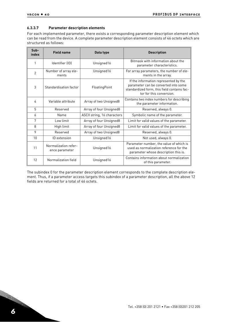
6.3.3.7 Parameter description elementsFor each implemented parameter, there exists a corresponding parameter description element which can be read from the device. A complete parameter description element consists of 46 octets which are structured as follows:
The subindex 0 for the parameter description element corresponds to the complete description ele-ment. Thus, if a parameter access targets this subindex of a parameter description, all the above 12 fields are returned for a total of 46 octets.
Sub- index Field name Data type Description
1 Identifier (ID) Unsigned16Bitmask with information about the
parameter characteristics.
2Number of array ele-
mentsUnsigned16 For array parameters, the number of ele-
ments in the array.
3 Standardisation factor FloatingPoint
If the information represented by the parameter can be converted into some
standardized form, this field contains fac-tor for this conversion.
4 Variable attribute Array of two Unsigned8Contains two index numbers for describing
the parameter information.
5 Reserved Array of four Unsigned8 Reserved, always 0.
6 Name ASCII string, 16 characters Symbolic name of the parameter.
7 Low limit Array of four Unsigned8 Limit for valid values of the parameter.
8 High limit Array of four Unsigned8 Limit for valid values of the parameter.
9 Reserved Array of two Unsigned8 Reserved, always 0.
10 ID extension Unsigned16 Not used, always 0.
11Normalization refer-
ence parameterUnsigned16
Parameter number, the value of which is used as normalization reference for the
parameter whose description this is.
12 Normalization field Unsigned16Contains information about normalization
of this parameter.
Tel. +358 (0) 201 2121 • Fax +358 (0)201 212 205
PROFIBUS DP interface vacon • 41
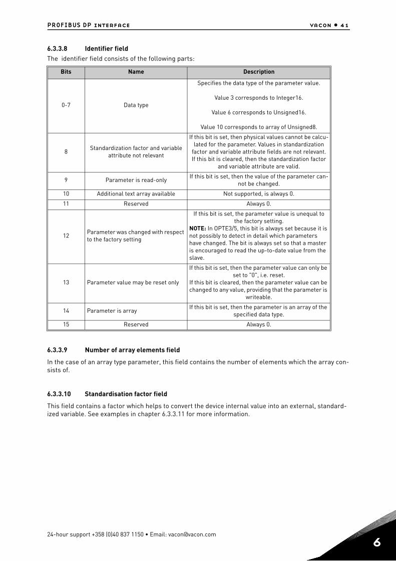
6.3.3.8 Identifier fieldThe identifier field consists of the following parts:
6.3.3.9 Number of array elements field
In the case of an array type parameter, this field contains the number of elements which the array con-sists of.
6.3.3.10 Standardisation factor field
This field contains a factor which helps to convert the device internal value into an external, standard-ized variable. See examples in chapter 6.3.3.11 for more information.
Bits Name Description
0-7 Data type
Specifies the data type of the parameter value.
Value 3 corresponds to Integer16.
Value 6 corresponds to Unsigned16.
Value 10 corresponds to array of Unsigned8.
8Standardization factor and variable
attribute not relevant
If this bit is set, then physical values cannot be calcu-lated for the parameter. Values in standardization
factor and variable attribute fields are not relevant.If this bit is cleared, then the standardization factor
and variable attribute are valid.
9 Parameter is read-onlyIf this bit is set, then the value of the parameter can-
not be changed.
10 Additional text array available Not supported, is always 0.
11 Reserved Always 0.
12Parameter was changed with respect to the factory setting
If this bit is set, the parameter value is unequal to the factory setting.
NOTE: In OPTE3/5, this bit is always set because it is not possibly to detect in detail which parameters have changed. The bit is always set so that a master is encouraged to read the up-to-date value from the slave.
13 Parameter value may be reset only
If this bit is set, then the parameter value can only be set to "0", i.e. reset.
If this bit is cleared, then the parameter value can be changed to any value, providing that the parameter is
writeable.
14 Parameter is arrayIf this bit is set, then the parameter is an array of the
specified data type.
15 Reserved Always 0.
24-hour support +358 (0)40 837 1150 • Email: [email protected]
6
6
vacon • 42 PROFIBUS DP interface
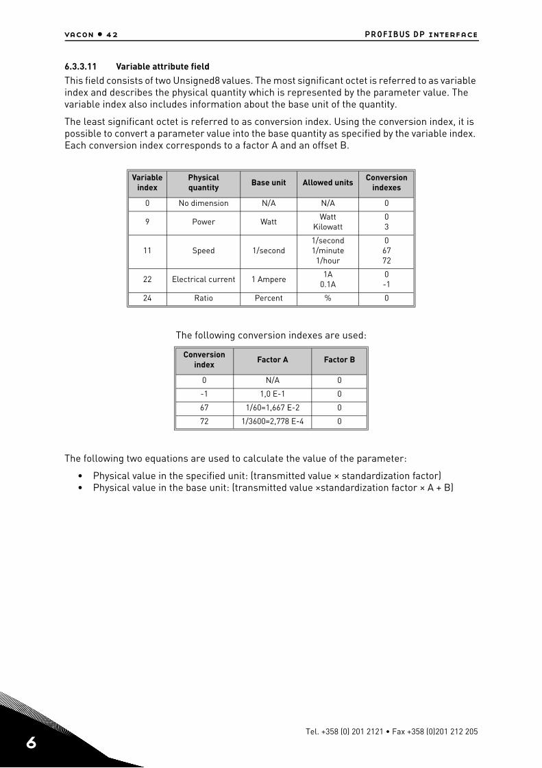
6.3.3.11 Variable attribute field
This field consists of two Unsigned8 values. The most significant octet is referred to as variable index and describes the physical quantity which is represented by the parameter value. The variable index also includes information about the base unit of the quantity.
The least significant octet is referred to as conversion index. Using the conversion index, it is possible to convert a parameter value into the base quantity as specified by the variable index. Each conversion index corresponds to a factor A and an offset B.
The following conversion indexes are used:
The following two equations are used to calculate the value of the parameter:
• Physical value in the specified unit: (transmitted value × standardization factor)• Physical value in the base unit: (transmitted value ×standardization factor × A + B)
Variable index
Physicalquantity Base unit Allowed units
Conversion indexes
0 No dimension N/A N/A 0
9 Power WattWatt
Kilowatt03
11 Speed 1/second1/second1/minute
1/hour
06772
22 Electrical current 1 Ampere1A
0.1A0-1
24 Ratio Percent % 0
Conversion index
Factor A Factor B
0 N/A 0
-1 1,0 E-1 0
67 1/60=1,667 E-2 0
72 1/3600=2,778 E-4 0
Tel. +358 (0) 201 2121 • Fax +358 (0)201 212 205
PROFIBUS DP interface vacon • 43
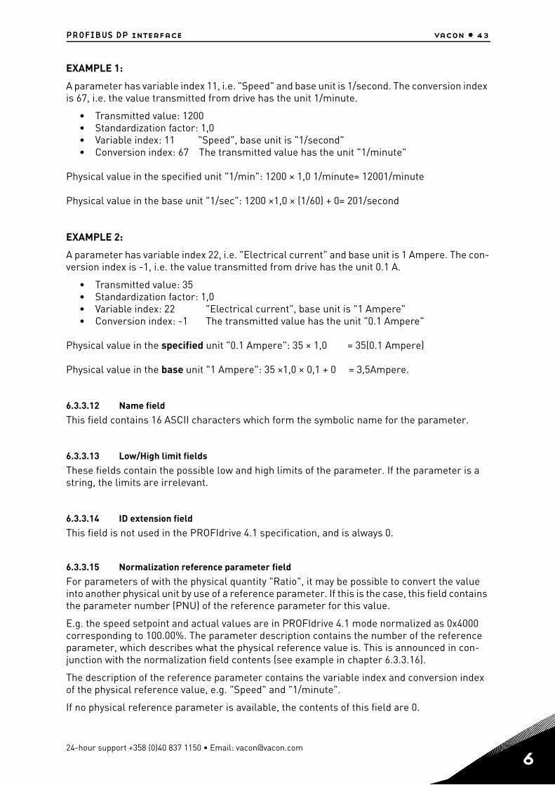
EXAMPLE 1:
A parameter has variable index 11, i.e. "Speed" and base unit is 1/second. The conversion index is 67, i.e. the value transmitted from drive has the unit 1/minute.
• Transmitted value: 1200• Standardization factor: 1,0• Variable index: 11 "Speed", base unit is "1/second"• Conversion index: 67 The transmitted value has the unit "1/minute"
Physical value in the specified unit "1/min": 1200 × 1,0 1/minute= 12001/minute
Physical value in the base unit "1/sec": 1200 ×1,0 × (1/60) + 0= 201/second
EXAMPLE 2:
A parameter has variable index 22, i.e. "Electrical current" and base unit is 1 Ampere. The con-version index is -1, i.e. the value transmitted from drive has the unit 0.1 A.
• Transmitted value: 35• Standardization factor: 1,0• Variable index: 22 "Electrical current", base unit is "1 Ampere"• Conversion index: -1 The transmitted value has the unit "0.1 Ampere"
Physical value in the specified unit "0.1 Ampere": 35 × 1,0 = 35(0.1 Ampere)
Physical value in the base unit "1 Ampere": 35 ×1,0 × 0,1 + 0 = 3,5Ampere.
6.3.3.12 Name field
This field contains 16 ASCII characters which form the symbolic name for the parameter.
6.3.3.13 Low/High limit fields
These fields contain the possible low and high limits of the parameter. If the parameter is a string, the limits are irrelevant.
6.3.3.14 ID extension field
This field is not used in the PROFIdrive 4.1 specification, and is always 0.
6.3.3.15 Normalization reference parameter field
For parameters of with the physical quantity "Ratio", it may be possible to convert the value into another physical unit by use of a reference parameter. If this is the case, this field contains the parameter number (PNU) of the reference parameter for this value.
E.g. the speed setpoint and actual values are in PROFIdrive 4.1 mode normalized as 0x4000 corresponding to 100.00%. The parameter description contains the number of the reference parameter, which describes what the physical reference value is. This is announced in con-junction with the normalization field contents (see example in chapter 6.3.3.16).
The description of the reference parameter contains the variable index and conversion index of the physical reference value, e.g. "Speed" and "1/minute".
If no physical reference parameter is available, the contents of this field are 0.
24-hour support +358 (0)40 837 1150 • Email: [email protected]
6
6
vacon • 44 PROFIBUS DP interface
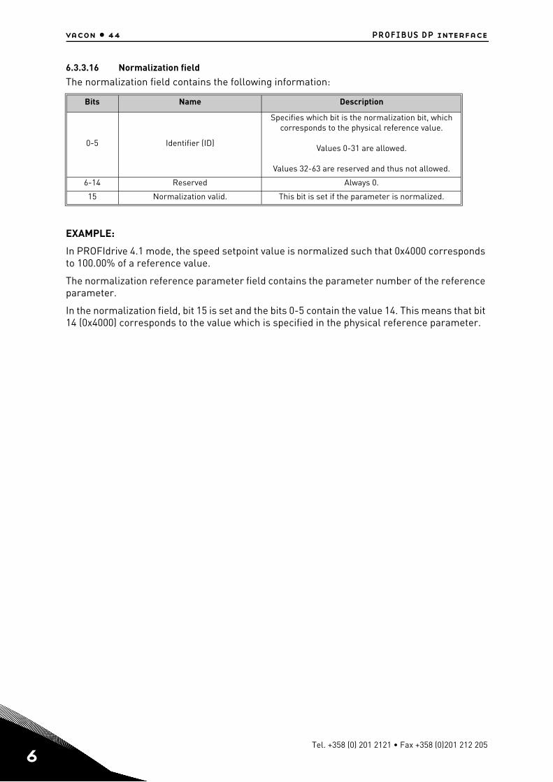
6.3.3.16 Normalization field
The normalization field contains the following information:
EXAMPLE:
In PROFIdrive 4.1 mode, the speed setpoint value is normalized such that 0x4000 corresponds to 100.00% of a reference value.
The normalization reference parameter field contains the parameter number of the reference parameter.
In the normalization field, bit 15 is set and the bits 0-5 contain the value 14. This means that bit 14 (0x4000) corresponds to the value which is specified in the physical reference parameter.
Bits Name Description
0-5 Identifier (ID)
Specifies which bit is the normalization bit, which corresponds to the physical reference value.
Values 0-31 are allowed.
Values 32-63 are reserved and thus not allowed.
6-14 Reserved Always 0.
15 Normalization valid. This bit is set if the parameter is normalized.
Tel. +358 (0) 201 2121 • Fax +358 (0)201 212 205
PROFIBUS DP interface vacon • 45
6.3.4 Example requests and responses
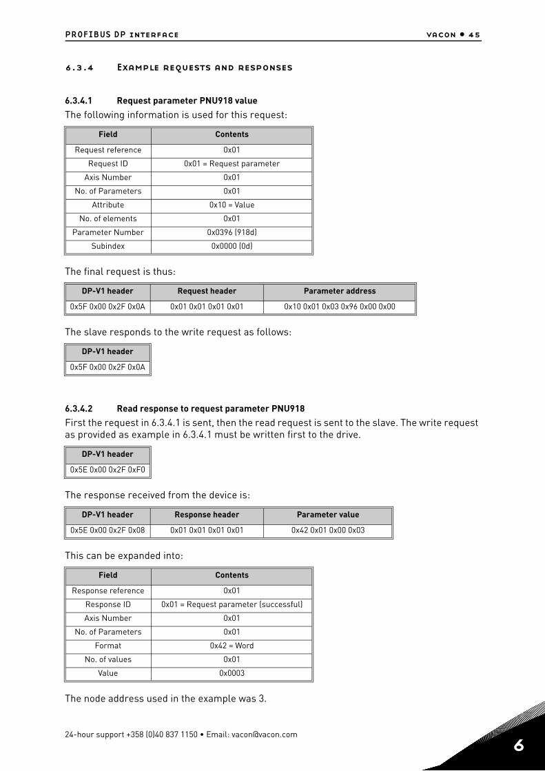
6.3.4.1 Request parameter PNU918 value
The following information is used for this request:
The final request is thus:
The slave responds to the write request as follows:
6.3.4.2 Read response to request parameter PNU918
First the request in 6.3.4.1 is sent, then the read request is sent to the slave. The write request as provided as example in 6.3.4.1 must be written first to the drive.
The response received from the device is:
This can be expanded into:
The node address used in the example was 3.
Field Contents
Request reference 0x01
Request ID 0x01 = Request parameter
Axis Number 0x01
No. of Parameters 0x01
Attribute 0x10 = Value
No. of elements 0x01
Parameter Number 0x0396 (918d)
Subindex 0x0000 (0d)
DP-V1 header Request header Parameter address
0x5F 0x00 0x2F 0x0A 0x01 0x01 0x01 0x01 0x10 0x01 0x03 0x96 0x00 0x00
DP-V1 header
0x5F 0x00 0x2F 0x0A
DP-V1 header
0x5E 0x00 0x2F 0xF0
DP-V1 header Response header Parameter value
0x5E 0x00 0x2F 0x08 0x01 0x01 0x01 0x01 0x42 0x01 0x00 0x03
Field Contents
Response reference 0x01
Response ID 0x01 = Request parameter (successful)
Axis Number 0x01
No. of Parameters 0x01
Format 0x42 = Word
No. of values 0x01
Value 0x0003
24-hour support +358 (0)40 837 1150 • Email: [email protected]
6
6
vacon • 46 PROFIBUS DP interface
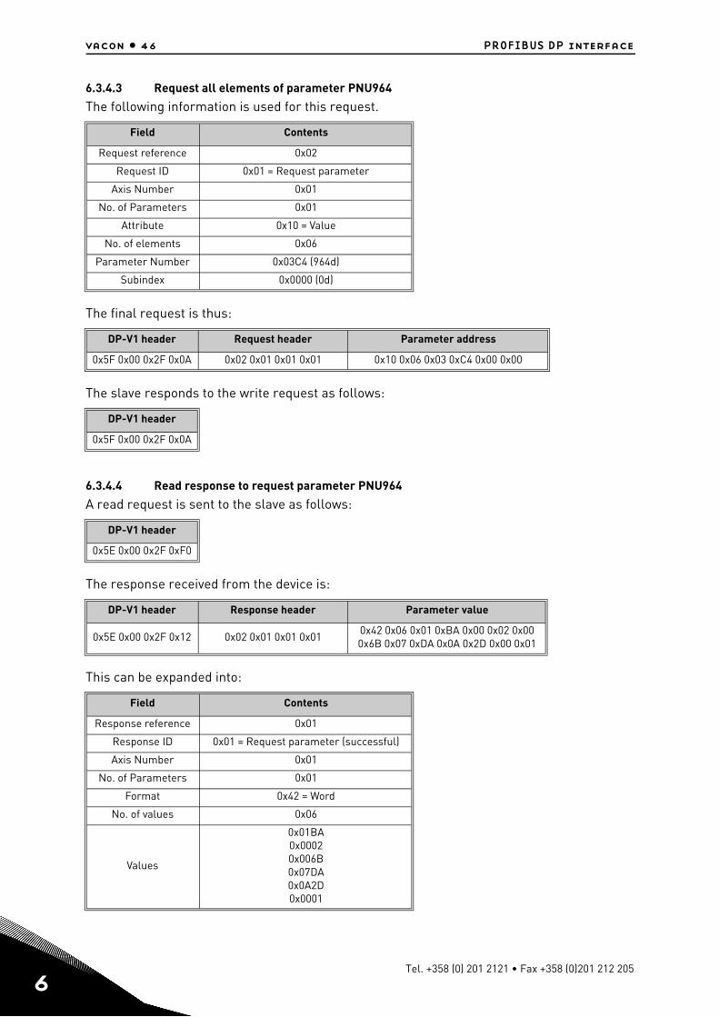
6.3.4.3 Request all elements of parameter PNU964
The following information is used for this request.
The final request is thus:
The slave responds to the write request as follows:
6.3.4.4 Read response to request parameter PNU964
A read request is sent to the slave as follows:
The response received from the device is:
This can be expanded into:
Field Contents
Request reference 0x02
Request ID 0x01 = Request parameter
Axis Number 0x01
No. of Parameters 0x01
Attribute 0x10 = Value
No. of elements 0x06
Parameter Number 0x03C4 (964d)
Subindex 0x0000 (0d)
DP-V1 header Request header Parameter address
0x5F 0x00 0x2F 0x0A 0x02 0x01 0x01 0x01 0x10 0x06 0x03 0xC4 0x00 0x00
DP-V1 header
0x5F 0x00 0x2F 0x0A
DP-V1 header
0x5E 0x00 0x2F 0xF0
DP-V1 header Response header Parameter value
0x5E 0x00 0x2F 0x12 0x02 0x01 0x01 0x010x42 0x06 0x01 0xBA 0x00 0x02 0x00 0x6B 0x07 0xDA 0x0A 0x2D 0x00 0x01
Field Contents
Response reference 0x01
Response ID 0x01 = Request parameter (successful)
Axis Number 0x01
No. of Parameters 0x01
Format 0x42 = Word
No. of values 0x06
Values
0x01BA0x00020x006B0x07DA0x0A2D0x0001
Tel. +358 (0) 201 2121 • Fax +358 (0)201 212 205
PROFIBUS DP interface vacon • 47
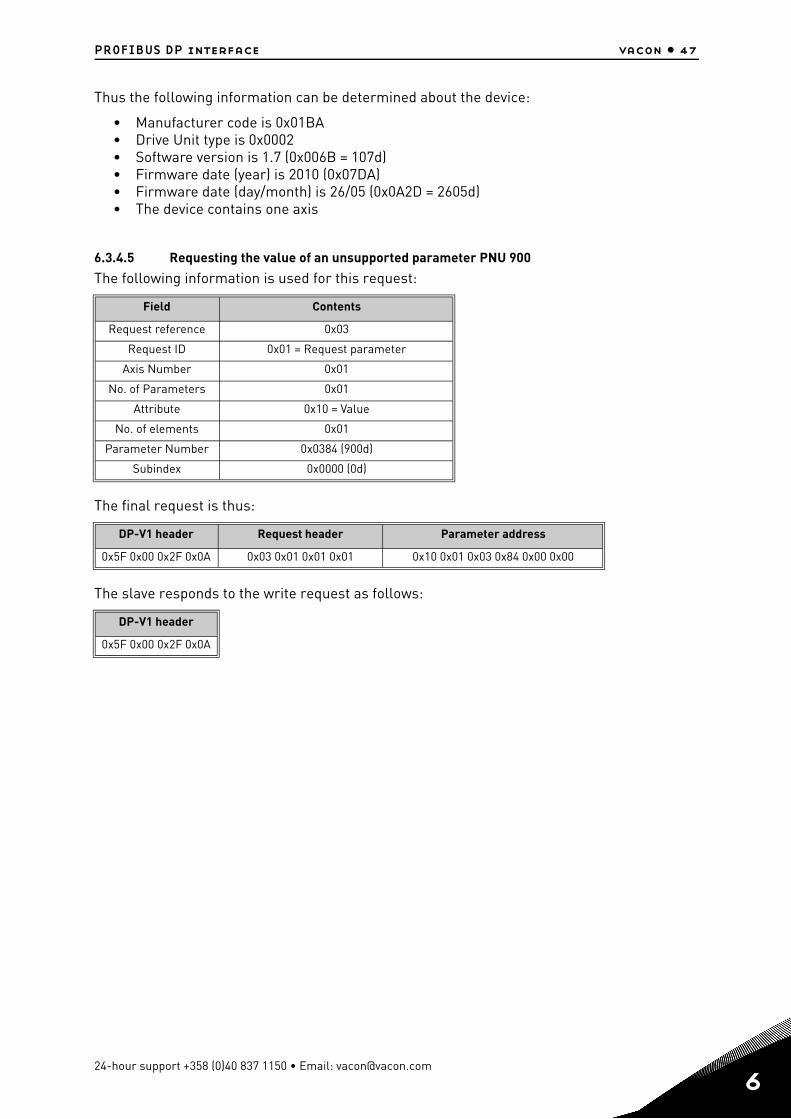
Thus the following information can be determined about the device:
• Manufacturer code is 0x01BA• Drive Unit type is 0x0002• Software version is 1.7 (0x006B = 107d)• Firmware date (year) is 2010 (0x07DA)• Firmware date (day/month) is 26/05 (0x0A2D = 2605d)• The device contains one axis
6.3.4.5 Requesting the value of an unsupported parameter PNU 900
The following information is used for this request:
The final request is thus:
The slave responds to the write request as follows:
Field Contents
Request reference 0x03
Request ID 0x01 = Request parameter
Axis Number 0x01
No. of Parameters 0x01
Attribute 0x10 = Value
No. of elements 0x01
Parameter Number 0x0384 (900d)
Subindex 0x0000 (0d)
DP-V1 header Request header Parameter address
0x5F 0x00 0x2F 0x0A 0x03 0x01 0x01 0x01 0x10 0x01 0x03 0x84 0x00 0x00
DP-V1 header
0x5F 0x00 0x2F 0x0A
24-hour support +358 (0)40 837 1150 • Email: [email protected]
6
6
vacon • 48 PROFIBUS DP interface
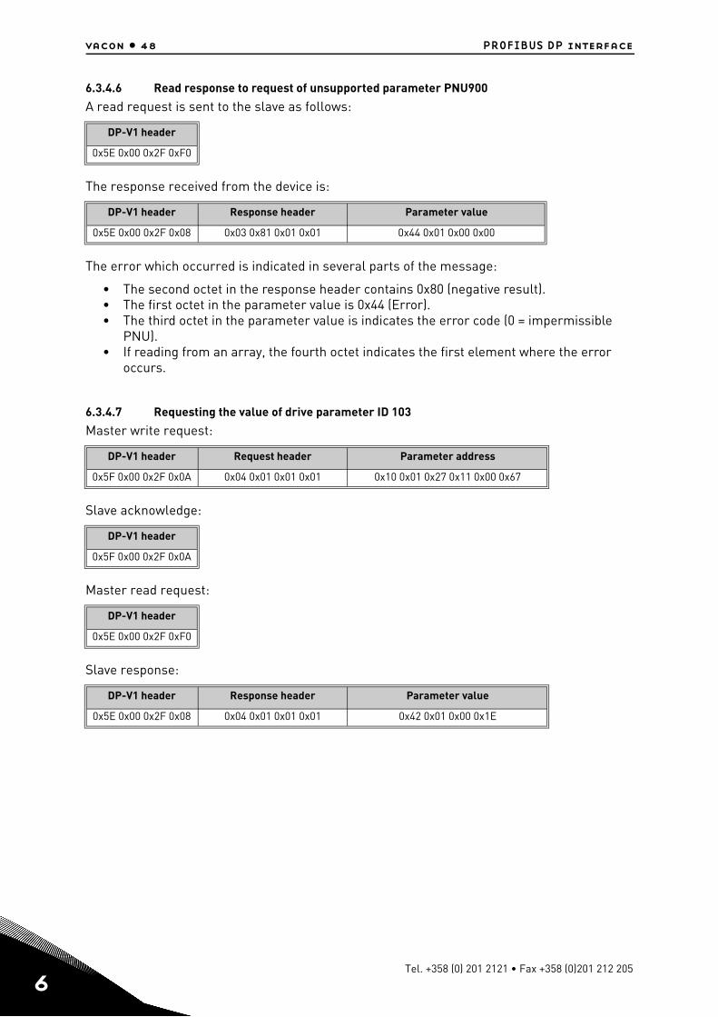
6.3.4.6 Read response to request of unsupported parameter PNU900
A read request is sent to the slave as follows:
The response received from the device is:
The error which occurred is indicated in several parts of the message:
• The second octet in the response header contains 0x80 (negative result).• The first octet in the parameter value is 0x44 (Error).• The third octet in the parameter value is indicates the error code (0 = impermissible
PNU).• If reading from an array, the fourth octet indicates the first element where the error
occurs.
6.3.4.7 Requesting the value of drive parameter ID 103
Master write request:
Slave acknowledge:
Master read request:
Slave response:
DP-V1 header
0x5E 0x00 0x2F 0xF0
DP-V1 header Response header Parameter value
0x5E 0x00 0x2F 0x08 0x03 0x81 0x01 0x01 0x44 0x01 0x00 0x00
DP-V1 header Request header Parameter address
0x5F 0x00 0x2F 0x0A 0x04 0x01 0x01 0x01 0x10 0x01 0x27 0x11 0x00 0x67
DP-V1 header
0x5F 0x00 0x2F 0x0A
DP-V1 header
0x5E 0x00 0x2F 0xF0
DP-V1 header Response header Parameter value
0x5E 0x00 0x2F 0x08 0x04 0x01 0x01 0x01 0x42 0x01 0x00 0x1E
Tel. +358 (0) 201 2121 • Fax +358 (0)201 212 205
PROFIBUS DP interface vacon • 49
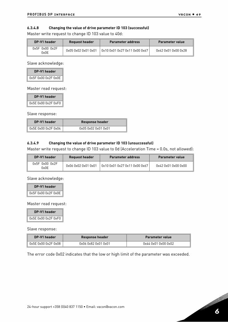
6.3.4.8 Changing the value of drive parameter ID 103 (successful)
Master write request to change ID 103 value to 40d:
Slave acknowledge:
Master read request:
Slave response:
6.3.4.9 Changing the value of drive parameter ID 103 (unsuccessful)
Master write request to change ID 103 value to 0d (Acceleration Time = 0.0s, not allowed):
Slave acknowledge:
Master read request:
Slave response:
The error code 0x02 indicates that the low or high limit of the parameter was exceeded.
DP-V1 header Request header Parameter address Parameter value
0x5F 0x00 0x2F 0x0E
0x05 0x02 0x01 0x01 0x10 0x01 0x27 0x11 0x00 0x67 0x42 0x01 0x00 0x28
DP-V1 header
0x5F 0x00 0x2F 0x0E
DP-V1 header
0x5E 0x00 0x2F 0xF0
DP-V1 header Response header
0x5E 0x00 0x2F 0x04 0x05 0x02 0x01 0x01
DP-V1 header Request header Parameter address Parameter value
0x5F 0x00 0x2F 0x0E
0x06 0x02 0x01 0x01 0x10 0x01 0x27 0x11 0x00 0x67 0x42 0x01 0x00 0x00
DP-V1 header
0x5F 0x00 0x2F 0x0E
DP-V1 header
0x5E 0x00 0x2F 0xF0
DP-V1 header Response header Parameter value
0x5E 0x00 0x2F 0x08 0x06 0x82 0x01 0x01 0x44 0x01 0x00 0x02
24-hour support +358 (0)40 837 1150 • Email: [email protected]
6
6
vacon • 50 PROFIBUS DP interface
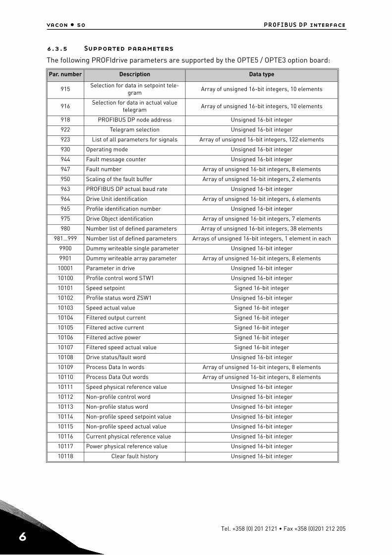
6.3.5 Supported parameters
The following PROFIdrive parameters are supported by the OPTE5 / OPTE3 option board:
Par. number Description Data type
915Selection for data in setpoint tele-
gramArray of unsigned 16-bit integers, 10 elements
916Selection for data in actual value
telegramArray of unsigned 16-bit integers, 10 elements
918 PROFIBUS DP node address Unsigned 16-bit integer
922 Telegram selection Unsigned 16-bit integer
923 List of all parameters for signals Array of unsigned 16-bit integers, 122 elements
930 Operating mode Unsigned 16-bit integer
944 Fault message counter Unsigned 16-bit integer
947 Fault number Array of unsigned 16-bit integers, 8 elements
950 Scaling of the fault buffer Array of unsigned 16-bit integers, 2 elements
963 PROFIBUS DP actual baud rate Unsigned 16-bit integer
964 Drive Unit identification Array of unsigned 16-bit integers, 6 elements
965 Profile identification number Unsigned 16-bit integer
975 Drive Object identification Array of unsigned 16-bit integers, 7 elements
980 Number list of defined parameters Array of unsigned 16-bit integers, 38 elements
981…999 Number list of defined parameters Arrays of unsigned 16-bit integers, 1 element in each
9900 Dummy writeable single parameter Unsigned 16-bit integer
9901 Dummy writeable array parameter Array of unsigned 16-bit integers, 8 elements
10001 Parameter in drive Unsigned 16-bit integer
10100 Profile control word STW1 Unsigned 16-bit integer
10101 Speed setpoint Signed 16-bit integer
10102 Profile status word ZSW1 Unsigned 16-bit integer
10103 Speed actual value Signed 16-bit integer
10104 Filtered output current Signed 16-bit integer
10105 Filtered active current Signed 16-bit integer
10106 Filtered active power Signed 16-bit integer
10107 Filtered speed actual value Signed 16-bit integer
10108 Drive status/fault word Unsigned 16-bit integer
10109 Process Data In words Array of unsigned 16-bit integers, 8 elements
10110 Process Data Out words Array of unsigned 16-bit integers, 8 elements
10111 Speed physical reference value Unsigned 16-bit integer
10112 Non-profile control word Unsigned 16-bit integer
10113 Non-profile status word Unsigned 16-bit integer
10114 Non-profile speed setpoint value Unsigned 16-bit integer
10115 Non-profile speed actual value Unsigned 16-bit integer
10116 Current physical reference value Unsigned 16-bit integer
10117 Power physical reference value Unsigned 16-bit integer
10118 Clear fault history Unsigned 16-bit integer
Tel. +358 (0) 201 2121 • Fax +358 (0)201 212 205
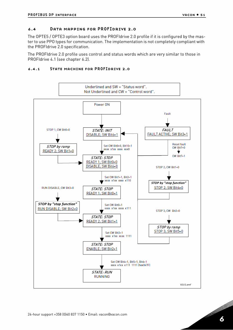
PROFIBUS DP interface vacon • 51
6.4 Data mapping for PROFIdrive 2.0
The OPTE5 / OPTE3 option board uses the PROFIdrive 2.0 profile if it is configured by the mas-ter to use PPO types for communication. The implementation is not completely compliant with the PROFIdrive 2.0 specification.
The PROFIdrive 2.0 profile uses control and status words which are very similar to those in PROFIdrive 4.1 (see chapter 6.2).
6.4.1 State machine for PROFIdrive 2.0
STOP by ”stop function”
STOP by ”stop function”
9315.emf
24-hour support +358 (0)40 837 1150 • Email: [email protected]
6
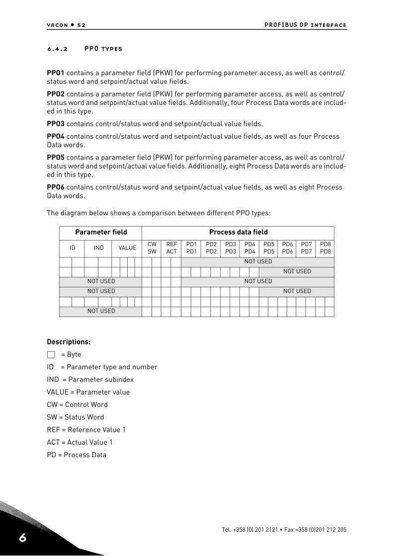
6
vacon • 52 PROFIBUS DP interface
6.4.2 PPO types
PPO1 contains a parameter field (PKW) for performing parameter access, as well as control/status word and setpoint/actual value fields.
PPO2 contains a parameter field (PKW) for performing parameter access, as well as control/status word and setpoint/actual value fields. Additionally, four Process Data words are includ-ed in this type.
PPO3 contains control/status word and setpoint/actual value fields.
PPO4 contains control/status word and setpoint/actual value fields, as well as four Process Data words.
PPO5 contains a parameter field (PKW) for performing parameter access, as well as control/status word and setpoint/actual value fields. Additionally, eight Process Data words are includ-ed in this type.
PPO6 contains control/status word and setpoint/actual value fields, as well as eight Process Data words.
The diagram below shows a comparison between different PPO types:
Descriptions:
= Byte
ID = Parameter type and number
IND = Parameter subindex
VALUE = Parameter value
CW = Control Word
SW = Status Word
REF = Reference Value 1
ACT = Actual Value 1
PD = Process Data
Parameter field Process data field
ID IND VALUECWSW
REFACT
PD1PD1
PD2PD2
PD3PD3
PD4PD4
PD5PD5
PD6PD6
PD7PD7
PD8PD8
NOT USED
NOT USED
NOT USED NOT USED
NOT USED NOT USED
NOT USED
Tel. +358 (0) 201 2121 • Fax +358 (0)201 212 205
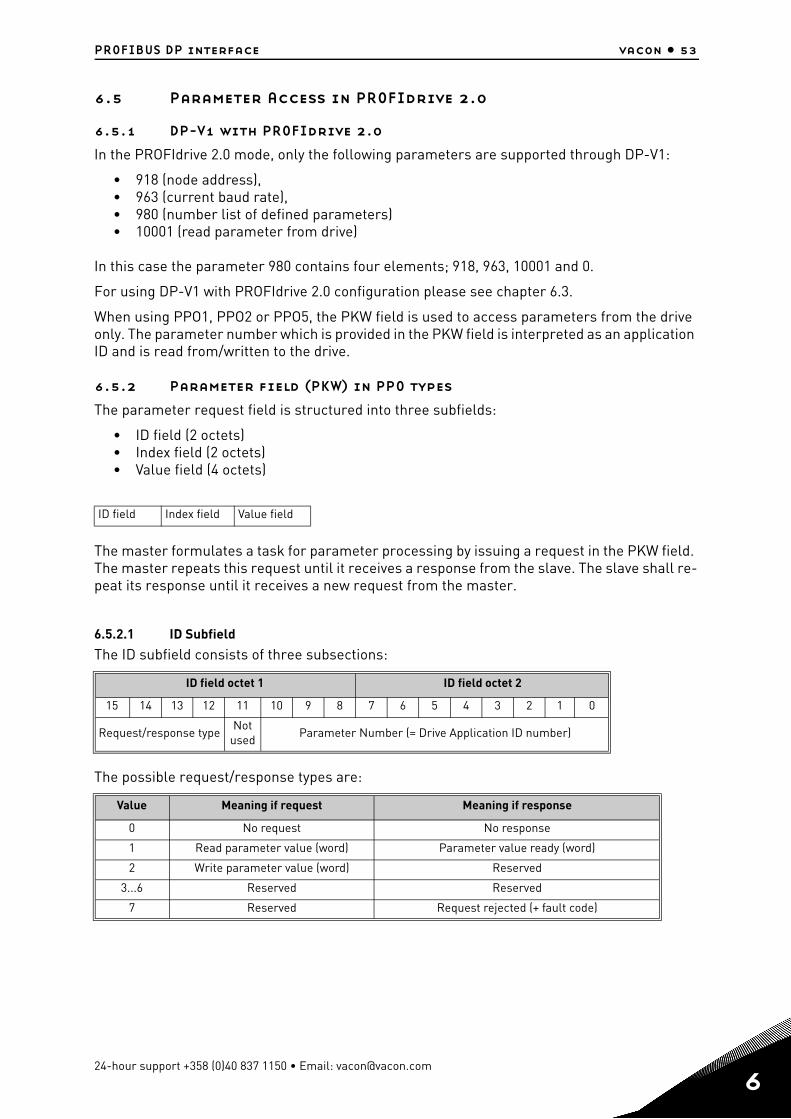
PROFIBUS DP interface vacon • 53
6.5 Parameter Access in PROFIdrive 2.0
6.5.1 DP-V1 with PROFIdrive 2.0
In the PROFIdrive 2.0 mode, only the following parameters are supported through DP-V1:
• 918 (node address),• 963 (current baud rate),• 980 (number list of defined parameters)• 10001 (read parameter from drive)
In this case the parameter 980 contains four elements; 918, 963, 10001 and 0.
For using DP-V1 with PROFIdrive 2.0 configuration please see chapter 6.3.
When using PPO1, PPO2 or PPO5, the PKW field is used to access parameters from the drive only. The parameter number which is provided in the PKW field is interpreted as an application ID and is read from/written to the drive.
6.5.2 Parameter field (PKW) in PPO types
The parameter request field is structured into three subfields:
• ID field (2 octets)• Index field (2 octets)• Value field (4 octets)
The master formulates a task for parameter processing by issuing a request in the PKW field. The master repeats this request until it receives a response from the slave. The slave shall re-peat its response until it receives a new request from the master.
6.5.2.1 ID Subfield
The ID subfield consists of three subsections:
The possible request/response types are:
ID field Index field Value field
ID field octet 1 ID field octet 2
15 14 13 12 11 10 9 8 7 6 5 4 3 2 1 0
Request/response typeNot
usedParameter Number (= Drive Application ID number)
Value Meaning if request Meaning if response
0 No request No response
1 Read parameter value (word) Parameter value ready (word)
2 Write parameter value (word) Reserved
3...6 Reserved Reserved
7 Reserved Request rejected (+ fault code)
24-hour support +358 (0)40 837 1150 • Email: [email protected]
6
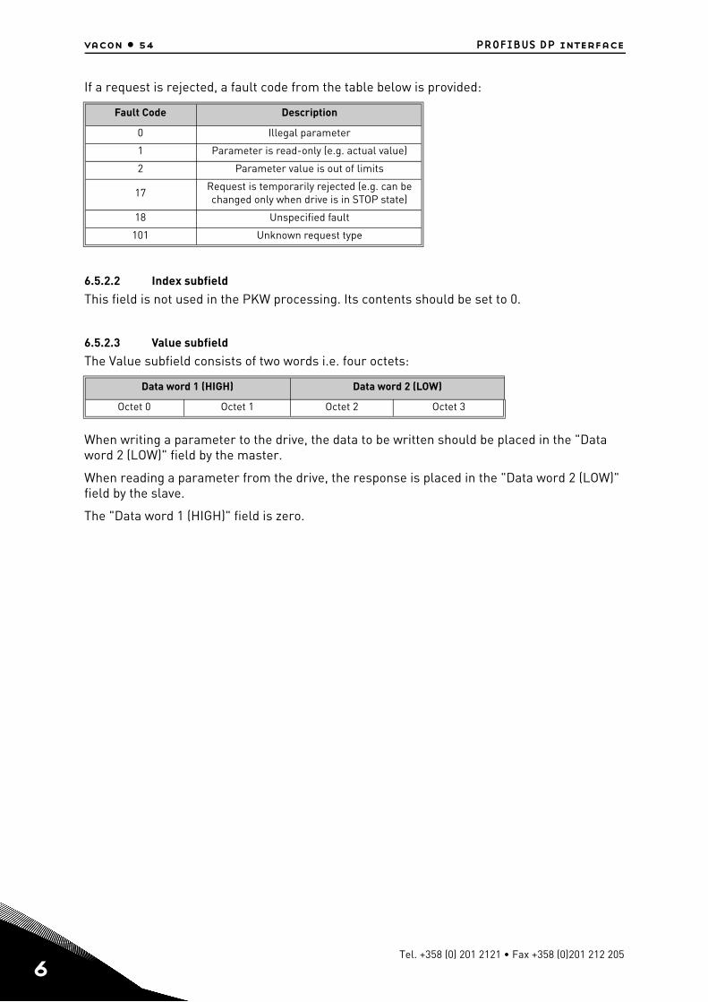
6
vacon • 54 PROFIBUS DP interface
If a request is rejected, a fault code from the table below is provided:
6.5.2.2 Index subfield
This field is not used in the PKW processing. Its contents should be set to 0.
6.5.2.3 Value subfield
The Value subfield consists of two words i.e. four octets:
When writing a parameter to the drive, the data to be written should be placed in the "Data word 2 (LOW)" field by the master.
When reading a parameter from the drive, the response is placed in the "Data word 2 (LOW)" field by the slave.
The "Data word 1 (HIGH)" field is zero.
Fault Code Description
0 Illegal parameter
1 Parameter is read-only (e.g. actual value)
2 Parameter value is out of limits
17Request is temporarily rejected (e.g. can be changed only when drive is in STOP state)
18 Unspecified fault
101 Unknown request type
Data word 1 (HIGH) Data word 2 (LOW)
Octet 0 Octet 1 Octet 2 Octet 3
Tel. +358 (0) 201 2121 • Fax +358 (0)201 212 205
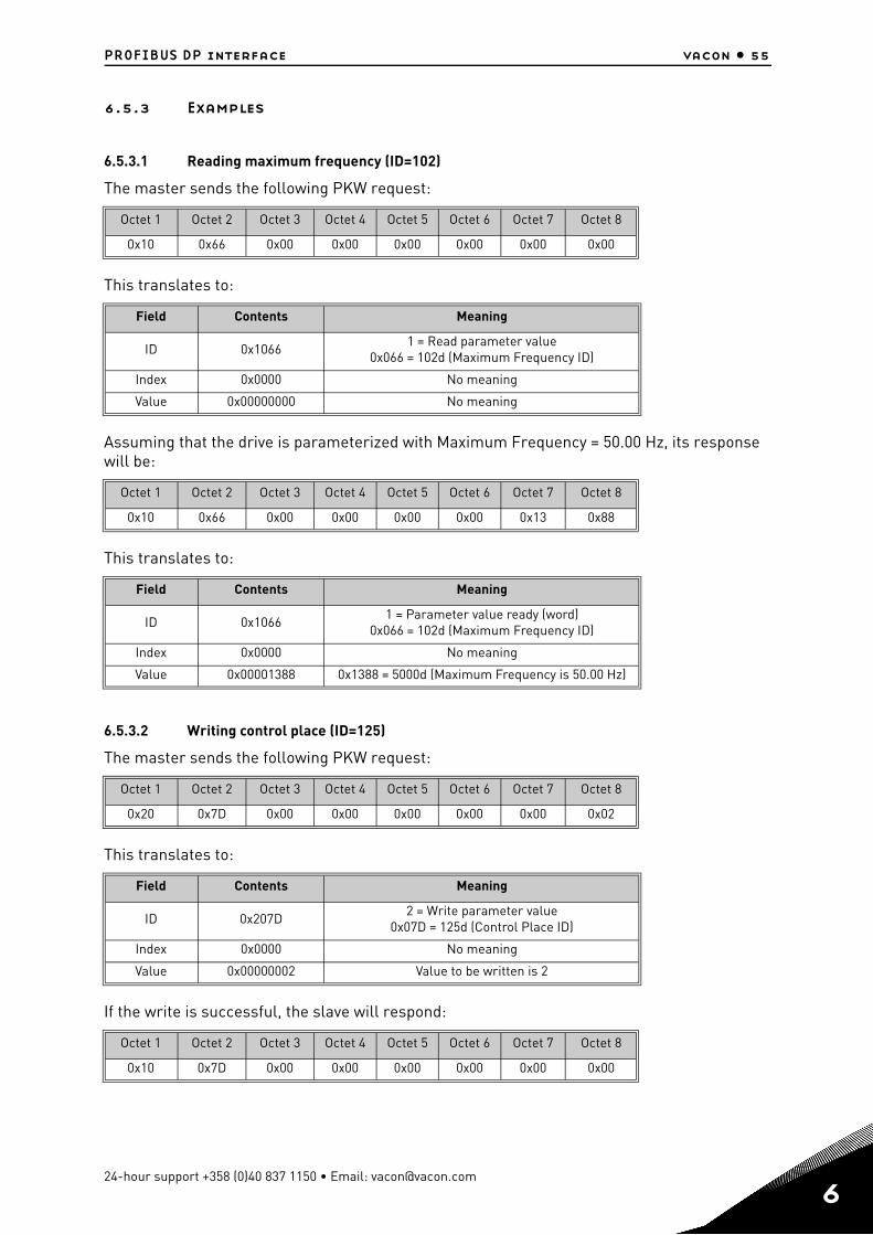
PROFIBUS DP interface vacon • 55
6.5.3 Examples
6.5.3.1 Reading maximum frequency (ID=102)
The master sends the following PKW request:
This translates to:
Assuming that the drive is parameterized with Maximum Frequency = 50.00 Hz, its response will be:
This translates to:
6.5.3.2 Writing control place (ID=125)
The master sends the following PKW request:
This translates to:
If the write is successful, the slave will respond:
Octet 1 Octet 2 Octet 3 Octet 4 Octet 5 Octet 6 Octet 7 Octet 8
0x10 0x66 0x00 0x00 0x00 0x00 0x00 0x00
Field Contents Meaning
ID 0x10661 = Read parameter value
0x066 = 102d (Maximum Frequency ID)
Index 0x0000 No meaning
Value 0x00000000 No meaning
Octet 1 Octet 2 Octet 3 Octet 4 Octet 5 Octet 6 Octet 7 Octet 8
0x10 0x66 0x00 0x00 0x00 0x00 0x13 0x88
Field Contents Meaning
ID 0x10661 = Parameter value ready (word)
0x066 = 102d (Maximum Frequency ID)
Index 0x0000 No meaning
Value 0x00001388 0x1388 = 5000d (Maximum Frequency is 50.00 Hz)
Octet 1 Octet 2 Octet 3 Octet 4 Octet 5 Octet 6 Octet 7 Octet 8
0x20 0x7D 0x00 0x00 0x00 0x00 0x00 0x02
Field Contents Meaning
ID 0x207D2 = Write parameter value
0x07D = 125d (Control Place ID)
Index 0x0000 No meaning
Value 0x00000002 Value to be written is 2
Octet 1 Octet 2 Octet 3 Octet 4 Octet 5 Octet 6 Octet 7 Octet 8
0x10 0x7D 0x00 0x00 0x00 0x00 0x00 0x00
24-hour support +358 (0)40 837 1150 • Email: [email protected]
6
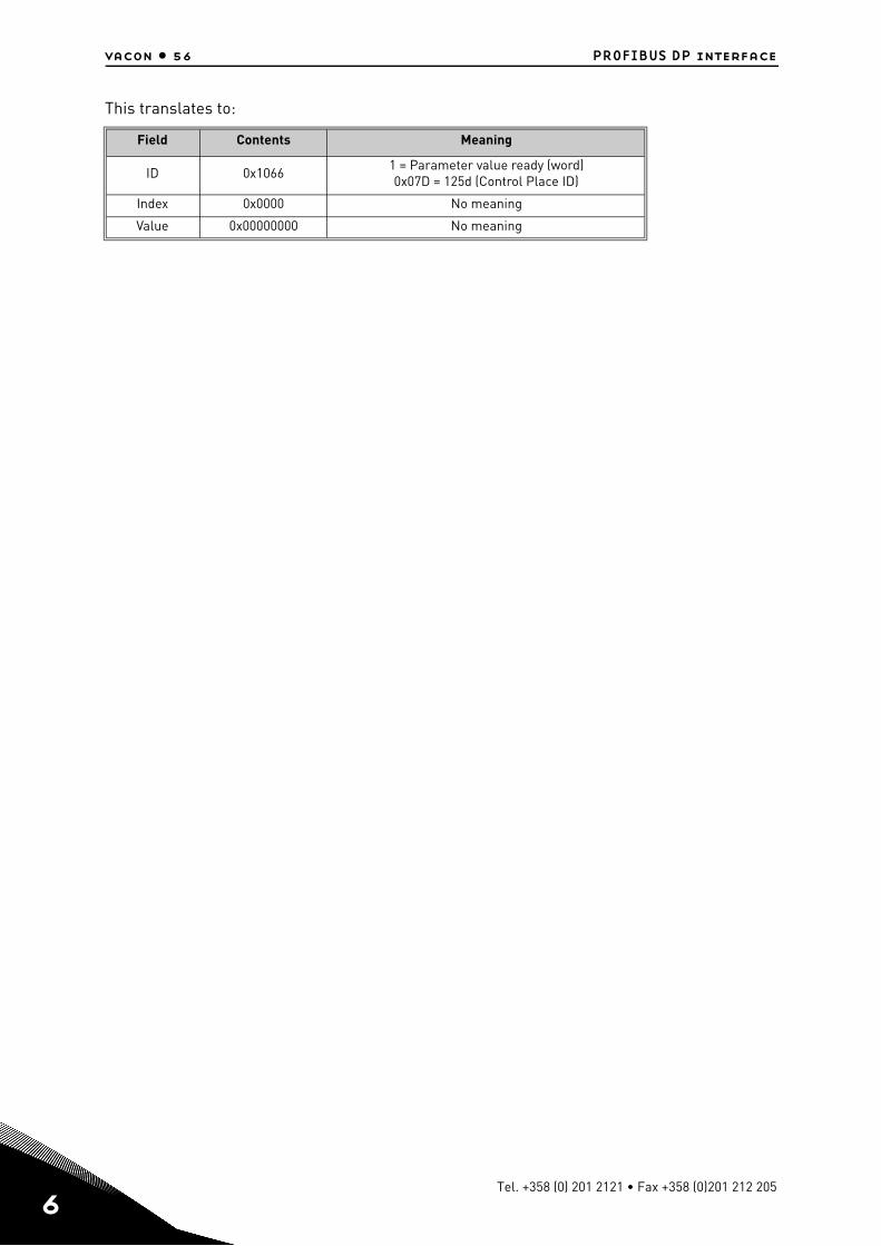
6
vacon • 56 PROFIBUS DP interface
This translates to:
Field Contents Meaning
ID 0x10661 = Parameter value ready (word)0x07D = 125d (Control Place ID)
Index 0x0000 No meaning
Value 0x00000000 No meaning
Tel. +358 (0) 201 2121 • Fax +358 (0)201 212 205
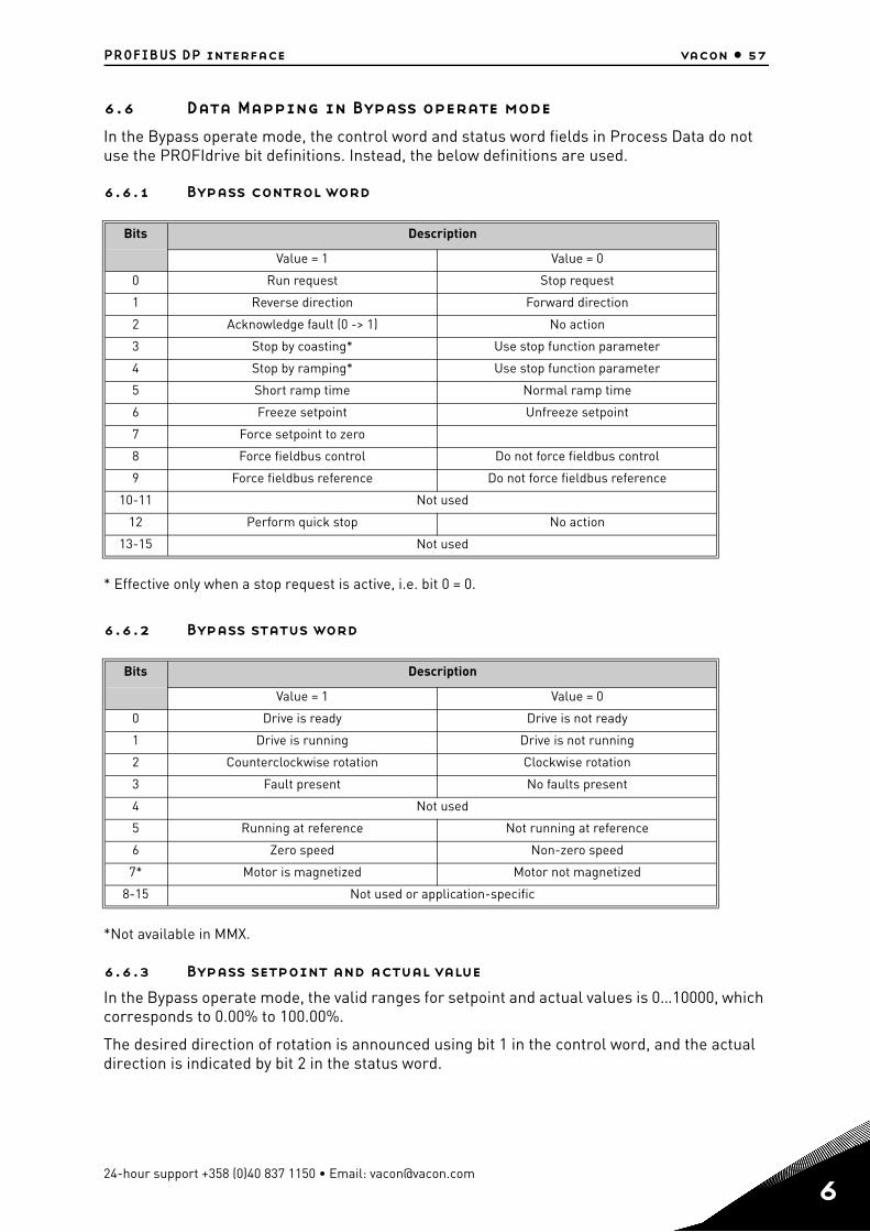
PROFIBUS DP interface vacon • 57
6.6 Data Mapping in Bypass operate mode
In the Bypass operate mode, the control word and status word fields in Process Data do not use the PROFIdrive bit definitions. Instead, the below definitions are used.
6.6.1 Bypass control word
* Effective only when a stop request is active, i.e. bit 0 = 0.
6.6.2 Bypass status word
*Not available in MMX.
6.6.3 Bypass setpoint and actual value
In the Bypass operate mode, the valid ranges for setpoint and actual values is 0…10000, which corresponds to 0.00% to 100.00%.
The desired direction of rotation is announced using bit 1 in the control word, and the actual direction is indicated by bit 2 in the status word.
Bits Description
Value = 1 Value = 0
0 Run request Stop request
1 Reverse direction Forward direction
2 Acknowledge fault (0 -> 1) No action
3 Stop by coasting* Use stop function parameter
4 Stop by ramping* Use stop function parameter
5 Short ramp time Normal ramp time
6 Freeze setpoint Unfreeze setpoint
7 Force setpoint to zero
8 Force fieldbus control Do not force fieldbus control
9 Force fieldbus reference Do not force fieldbus reference
10-11 Not used
12 Perform quick stop No action
13-15 Not used
Bits Description
Value = 1 Value = 0
0 Drive is ready Drive is not ready
1 Drive is running Drive is not running
2 Counterclockwise rotation Clockwise rotation
3 Fault present No faults present
4 Not used
5 Running at reference Not running at reference
6 Zero speed Non-zero speed
7* Motor is magnetized Motor not magnetized
8-15 Not used or application-specific
24-hour support +358 (0)40 837 1150 • Email: [email protected]
6
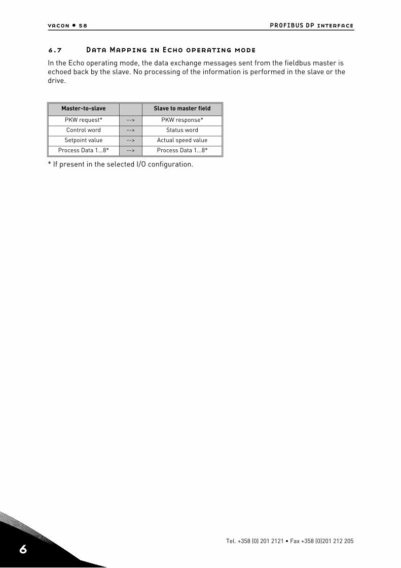
6
vacon • 58 PROFIBUS DP interface
6.7 Data Mapping in Echo operating mode
In the Echo operating mode, the data exchange messages sent from the fieldbus master is echoed back by the slave. No processing of the information is performed in the slave or the drive.
* If present in the selected I/O configuration.
Master-to-slave Slave to master field
PKW request* --> PKW response*
Control word --> Status word
Setpoint value --> Actual speed value
Process Data 1...8* --> Process Data 1...8*
Tel. +358 (0) 201 2121 • Fax +358 (0)201 212 205


Document ID:
Order code:
Rev. A
Manual authoring:[email protected]
Vacon Plc.Runsorintie 765380 VaasaFinland
Subject to change without prior notice© 2012 Vacon Plc.
Find your nearest Vacon office on the Internet at:
www.vacon.com
Find your nearest Vacon service centre on the Extranet at:
www.extra.vacon.com