Embed Size (px)
Citation preview
APPLICATION NOTE
R01AN0713EU0100 Rev.1.00 Page 1 of 24 November 15, 2011
V850ES/Jx3L USB and 78K0R/Lx3 Blood Pressure Monitor Reference Design
Introduction The measurement of the arterial blood pressure is of great clinical significance mainly for the detection and follow-up of hypertension which affects about one third of the adult population in the western world. Blood pressure varies considerably throughout the day and frequent blood pressure monitoring is required in many home healthcare situations. Blood pressure is measured by the medical personnel usually using ausculatory method. In this a pressure cuff is attached to the upper arm and inflated to compress the brachial artery to a value above the systolic pressure. Then, the cuff is gradually deflated while listening to Korotkoff sounds through stethoscope placed on the brachial artery distal to the cuff. The systolic and diastolic pressures are determined by reading the manometer when the sound begins and end, respectively. However this requires skill and not suitable for most home care environments.
There is a big need for automatic blood pressure measurement which can be used by patients themselves to keep track of their health. Most of the commercial noninvasive automatic blood pressure monitors use either Oscillometry or automatic detection of Korotkoff sounds or both. Both methods use a cuff to the upper arm and the systolic and diastolic pressures are determined automatically using an electronic instrument. The instrument has an electric pump and a pressure release valve apart from the electronics required to convert and display blood pressure readings. The cuff is inflated by an electric pump and deflated by a pressure-release valve. Proprietary algorithms are used to calculate systolic and diastolic blood pressure values.
Automatic oscillometric Blood Pressure monitors are the dominant types of noninvasive BP devices. There are many models on the market, ranging from professional monitors used in health care facilities to inexpensive monitors used in homes. Most home monitors are the upper arm (brachial) type, but wrist monitors are gaining popularity.
Contents
1. Digital Blood Pressure Monitor: ......................................................................................................... 3
2. Blood Pressure Monitor Requirements ............................................................................................. 6
3. Renesas V850ES/JG3-L Device Specifications ................................................................................ 8
4. Renesas 78K0R/Lx3 Device Specifications .................................................................................... 12
5. Reference Design Architecture ....................................................................................................... 16
6. Software Flowcharts ........................................................................................................................ 19
Appendix A - References ........................................................................................................................ 23
R01AN0713EU0100 Rev.1.00
November 15, 2011
V850ES/Jx3L USB and 78K0R/Lx3 Blood Pressure Monitor Reference Design
R01AN0713EU0100 Rev.1.00 Page 2 of 24 November 15, 2011
List of Figures Figure 1 Digital Blood Pressure Monitor ...................................................................................................................... 3
Figure 2 Blood Pressure Measurement Signal Flow Diagram ................................................................................. 4
Figure 3 Oscillometry ..................................................................................................................................................... 4
Figure 4 Block diagram of Blood Pressure Monitor ................................................................................................... 5
Figure 5 Device Architecture diagram ......................................................................................................................... 9
Figure 6 78K0R/Lx3 Device Architecture diagram ................................................................................................... 13
Figure 7 Hardware Implementation Diagram ............................................................................................................ 16
Figure 8 Low cost implementation using 78K0R/Lx3 device .................................................................................. 17
Figure 9 Software Architecture ................................................................................................................................... 18
Figure 10 Flowchart for Initialization .......................................................................................................................... 19
Figure 11 Flowchart for Pump control ........................................................................................................................ 20
Figure 12 Flowchart for Oscillometric Measurement (Method 1) ........................................................................... 20
Figure 13 Flowchart for Korotkoff measurement (Method 2).................................................................................. 21
Figure 14 Flowchart for Update measurement ......................................................................................................... 22
V850ES/Jx3L USB and 78K0R/Lx3 Blood Pressure Monitor Reference Design
R01AN0713EU0100 Rev.1.00 Page 3 of 24 November 15, 2011
1. Digital Blood Pressure Monitor:
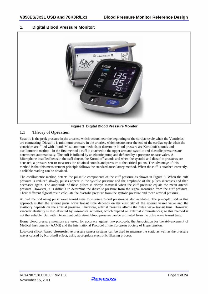
Figure 1 Digital Blood Pressure Monitor
1.1 Theory of Operation Systolic is the peak pressure in the arteries, which occurs near the beginning of the cardiac cycle when the Ventricles are contracting. Diastolic is minimum pressure in the arteries, which occurs near the end of the cardiac cycle when the ventricles are filled with blood. Most common methods to determine blood pressure are Korotkoff sounds and oscillometric method. In the first method a cuff is attached to the upper arm and systolic and diastolic pressures are determined automatically. The cuff is inflated by an electric pump and deflated by a pressure-release valve. A Microphone installed beneath the cuff detects the Korotkoff sounds and when the systolic and diastolic pressures are detected, a pressure sensor measures the obtained sounds and pressure at the critical points. The advantage of this method is that this measurement principle follows the standard ausculatory method. When the cuff is attached correctly, a reliable reading can be obtained.
The oscillometric method detects the pulsatile components of the cuff pressure as shown in Figure 3. When the cuff pressure is reduced slowly, pulses appear in the systolic pressure and the amplitude of the pulses increases and then decreases again. The amplitude of these pulses is always maximal when the cuff pressure equals the mean arterial pressure. However, it is difficult to determine the diastolic pressure from the signal measured from the cuff pressure. There different algorithms to calculate the diastolic pressure from the systolic pressure and mean arterial pressure.
A third method using pulse wave transit time to measure blood pressure is also available. The principle used in this approach is that the arterial pulse wave transit time depends on the elasticity of the arterial vessel valve and the elasticity depends on the arterial pressure. Therefore, arterial pressure affects the pulse wave transit time. However, vascular elasticity is also affected by vasomotor activities, which depend on external circumstances; so this method is not that reliable. But with intermittent calibration, blood pressure can be estimated from the pulse wave transit time.
Home blood pressure monitors are tested for accuracy against two protocols: the Association for the Advancement of Medical Instruments (AAMI) and the International Protocol of the European Society of Hypertension.
Low-cost silicon based piezoresistive pressure sensor systems can be used to measure the static as well as the pressure waves caused by Korotkoff effect, using appropriate electronic filtering process.
V850ES/Jx3L USB and 78K0R/Lx3 Blood Pressure Monitor Reference Design
R01AN0713EU0100 Rev.1.00 Page 4 of 24 November 15, 2011
1.2 Signal Processing
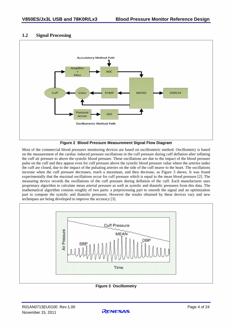
Figure 2 Blood Pressure Measurement Signal Flow Diagram
Most of the commercial blood pressures monitoring devices are based on oscillometric method. Oscillometry is based on the measurement of the cardiac induced pressure oscillations in the cuff pressure during cuff deflation after inflating the cuff air pressure to above the systolic blood pressure. These oscillations are due to the impact of the blood pressure pulse on the cuff and they appear even for cuff pressure above the systolic blood pressure value where the arteries under the cuff are closed, due to the impact of the pulsating arteries on the side of the cuff nearer to the heart. The oscillations increase when the cuff pressure decreases, reach a maximum, and then decrease, as Figure 3 shows. It was found experimentally that the maximal oscillations occur for cuff pressure which is equal to the mean blood pressure [2]. The measuring device records the oscillations of the cuff pressure during deflation of the cuff. Each manufacturer uses proprietary algorithm to calculate mean arterial pressure as well as systolic and diastolic pressures from this data. The mathematical algorithm consists roughly of two parts: a preprocessing part to smooth the signal and an optimization part to compute the systolic and diastolic pressures. However the results obtained by these devices vary and new techniques are being developed to improve the accuracy [3].
Figure 3 Oscillometry
V850ES/Jx3L USB and 78K0R/Lx3 Blood Pressure Monitor Reference Design
R01AN0713EU0100 Rev.1.00 Page 5 of 24 November 15, 2011
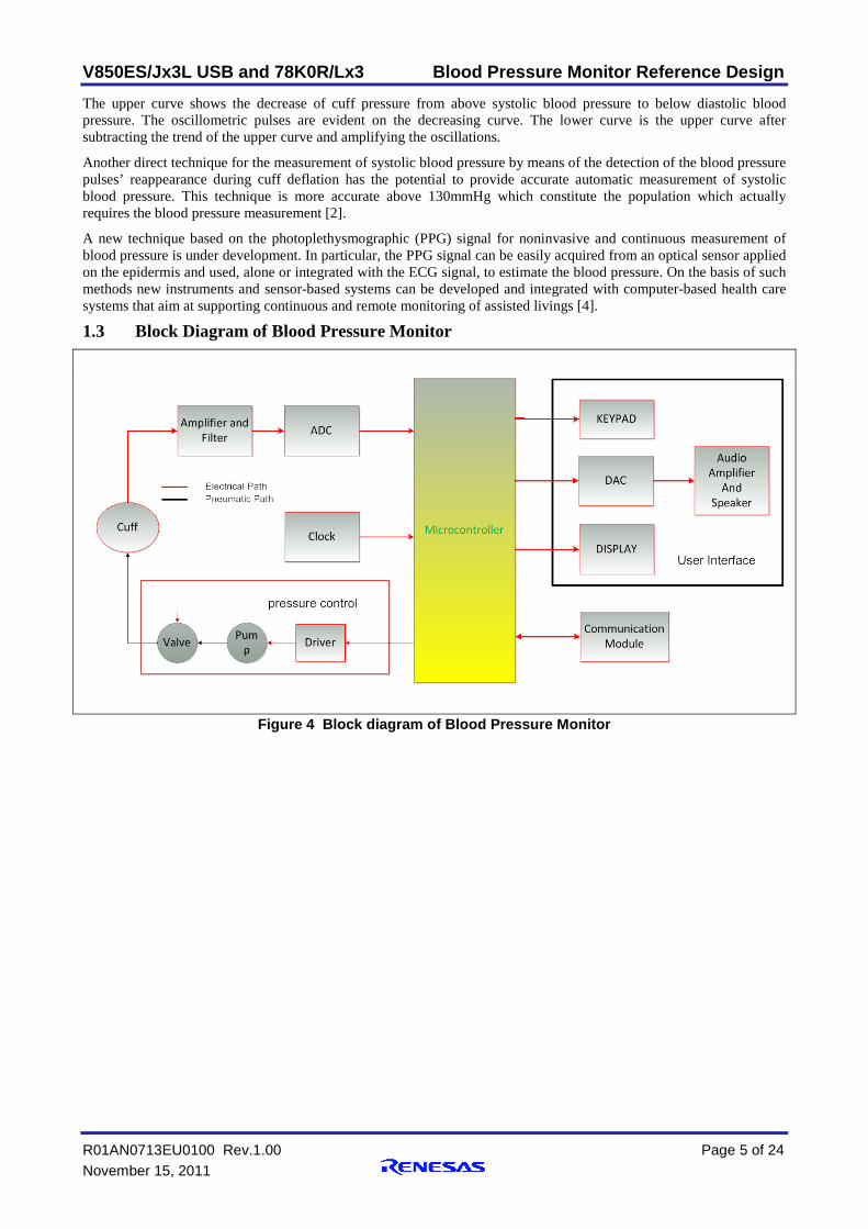
The upper curve shows the decrease of cuff pressure from above systolic blood pressure to below diastolic blood pressure. The oscillometric pulses are evident on the decreasing curve. The lower curve is the upper curve after subtracting the trend of the upper curve and amplifying the oscillations.
Another direct technique for the measurement of systolic blood pressure by means of the detection of the blood pressure pulses’ reappearance during cuff deflation has the potential to provide accurate automatic measurement of systolic blood pressure. This technique is more accurate above 130mmHg which constitute the population which actually requires the blood pressure measurement [2].
A new technique based on the photoplethysmographic (PPG) signal for noninvasive and continuous measurement of blood pressure is under development. In particular, the PPG signal can be easily acquired from an optical sensor applied on the epidermis and used, alone or integrated with the ECG signal, to estimate the blood pressure. On the basis of such methods new instruments and sensor-based systems can be developed and integrated with computer-based health care systems that aim at supporting continuous and remote monitoring of assisted livings [4].
1.3 Block Diagram of Blood Pressure Monitor
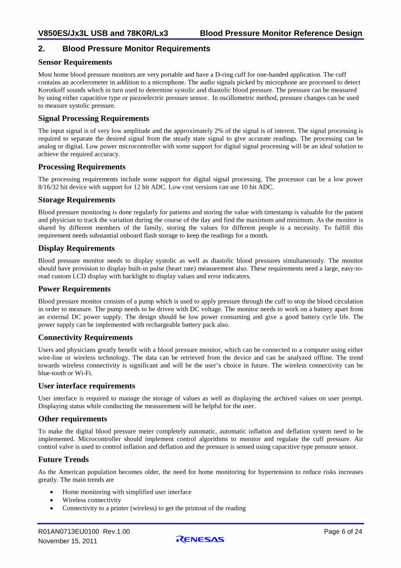
Figure 4 Block diagram of Blood Pressure Monitor
V850ES/Jx3L USB and 78K0R/Lx3 Blood Pressure Monitor Reference Design
R01AN0713EU0100 Rev.1.00 Page 6 of 24 November 15, 2011
2. Blood Pressure Monitor Requirements Sensor Requirements Most home blood pressure monitors are very portable and have a D-ring cuff for one-handed application. The cuff contains an accelerometer in addition to a microphone. The audio signals picked by microphone are processed to detect Korotkoff sounds which in turn used to determine systolic and diastolic blood pressure. The pressure can be measured by using either capacitive type or piezoelectric pressure sensor. In oscillometric method, pressure changes can be used to measure systolic pressure.
Signal Processing Requirements The input signal is of very low amplitude and the approximately 2% of the signal is of interest. The signal processing is required to separate the desired signal from the steady state signal to give accurate readings. The processing can be analog or digital. Low power microcontroller with some support for digital signal processing will be an ideal solution to achieve the required accuracy.
Processing Requirements The processing requirements include some support for digital signal processing. The processor can be a low power 8/16/32 bit device with support for 12 bit ADC. Low cost versions can use 10 bit ADC.
Storage Requirements Blood pressure monitoring is done regularly for patients and storing the value with timestamp is valuable for the patient and physician to track the variation during the course of the day and find the maximum and minimum. As the monitor is shared by different members of the family, storing the values for different people is a necessity. To fulfill this requirement needs substantial onboard flash storage to keep the readings for a month.
Display Requirements Blood pressure monitor needs to display systolic as well as diastolic blood pressures simultaneously. The monitor should have provision to display built-in pulse (heart rate) measurement also. These requirements need a large, easy-to-read custom LCD display with backlight to display values and error indicators.
Power Requirements Blood pressure monitor consists of a pump which is used to apply pressure through the cuff to stop the blood circulation in order to measure. The pump needs to be driven with DC voltage. The monitor needs to work on a battery apart from an external DC power supply. The design should be low power consuming and give a good battery cycle life. The power supply can be implemented with rechargeable battery pack also.
Connectivity Requirements Users and physicians greatly benefit with a blood pressure monitor, which can be connected to a computer using either wire-line or wireless technology. The data can be retrieved from the device and can be analyzed offline. The trend towards wireless connectivity is significant and will be the user’s choice in future. The wireless connectivity can be blue-tooth or Wi-Fi.
User interface requirements User interface is required to manage the storage of values as well as displaying the archived values on user prompt. Displaying status while conducting the measurement will be helpful for the user.
Other requirements To make the digital blood pressure meter completely automatic, automatic inflation and deflation system need to be implemented. Microcontroller should implement control algorithms to monitor and regulate the cuff pressure. Air control valve is used to control inflation and deflation and the pressure is sensed using capacitive type pressure sensor.
Future Trends As the American population becomes older, the need for home monitoring for hypertension to reduce risks increases greatly. The main trends are
• Home monitoring with simplified user interface • Wireless connectivity • Connectivity to a printer (wireless) to get the printout of the reading
V850ES/Jx3L USB and 78K0R/Lx3 Blood Pressure Monitor Reference Design
R01AN0713EU0100 Rev.1.00 Page 7 of 24 November 15, 2011
• Continuous monitoring of blood pressure to find the maximum and minimum during daily chores to find the cause. This requires a monitor with a micro drive to save the data or wireless connectivity to a network to log the data.
V850ES/Jx3L USB and 78K0R/Lx3 Blood Pressure Monitor Reference Design
R01AN0713EU0100 Rev.1.00 Page 8 of 24 November 15, 2011
3. Renesas V850ES/JG3-L Device Specifications
3.1 Renesas V850ES/JG3-L Device Architecture Overview The V850ES/JG3-L is a 32-bit single-chip microcontroller that includes the V850ES CPU core and peripheral functions such as ROM/RAM, timer/counters, serial interfaces, an A/D converter, a D/A converter, USB function controller. In addition to high real-time response characteristics and 1-clock-pitch basic instructions, the V850ES/JG3-L features multiply instructions, saturated operation instructions, bit manipulation instructions, etc., realized by a hardware multiplier, as optimum instructions for digital servo control applications.
Features Minimum instruction execution time: 50 ns (operating on main clock (fXX) of 20 MHz: VDD = 2.7 to 3.6 V) (In PLL mode: ×4 : 5 MHz) 62.5 ns (operating on main clock (fXX) of 16 MHz: VDD = 3.0 to 3.6 V) (In PLL mode: ×8, 1/3 : 6 MHz) 200 ns (operating on main clock (fXX) of 5 MHz: VDD = 2.2 to 3.6 V) (In clock-through mode) 400 ns (operating on main clock (fXX) of 2.5 MHz: VDD = 2.0 to 3.6 V) (In clock-through mode) 30.5 μs (operating on sub clock (fXT) of 32.768 kHz: VDD = 2.0 to 3.6 V) General-purpose registers:
• 32 bits × 32 registers CPU features:
• Signed multiplication (16 × 16 → 32): 1 to 2 clocks • Signed multiplication (32 × 32 → 64): 1 to 5 clocks • Saturated operations (overflow and underflow detection functions included) • Most instructions can be executed in 1 clock cycle by using 32-bit RISC-based 5-stage pipeline architecture • Instruction fetching from internal ROM and accessing internal RAM for data can be executed separately, by
using Harvard architecture • High code efficiency achieved by using variable length instructions • 32-bit shift instruction: 1 clock cycle • Bit manipulation instructions • Load/store instructions with long/short format
Memory space: • 64 MB of linear address space (for programs and data) • External expansion: Up to 16 MB (including 1 MB used as internal ROM/RAM) • Internal memory: RAM: 40 KB • Flash memory: 256/384/512 KB
External bus interface: • Separate bus/multiplexed bus output selectable • 8/16 bit data bus sizing function • Wait function
• Programmable wait function • External wait function
• Idle state function • Bus hold function
Interrupts and exceptions: • Internal external: • Maskable / Nonmaskable • Software exceptions: 32 sources • Exception trap: 2 sources
Ports: • I/O ports: 80
Timer function: • 16-bit interval timer M (TMM): 1 channel • 16-bit timer/event counter P (TMP): 6 channels • 16-bit timer/event counter Q (TMQ): 1 channel • Watch timer: 1 channel
V850ES/Jx3L USB and 78K0R/Lx3 Blood Pressure Monitor Reference Design
R01AN0713EU0100 Rev.1.00 Page 9 of 24 November 15, 2011
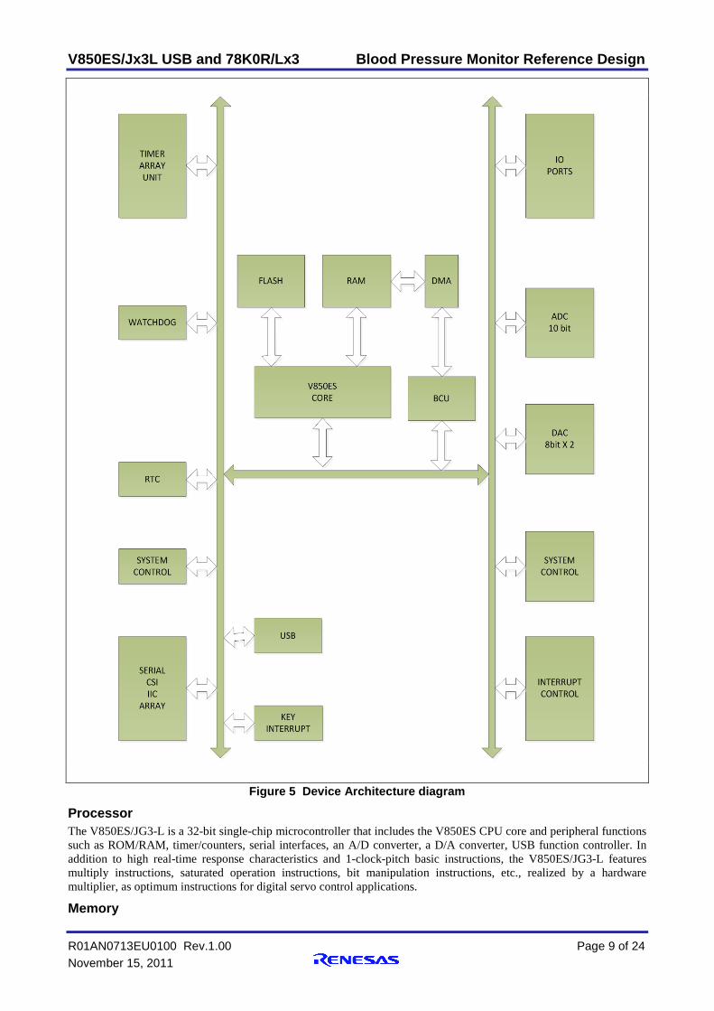
Figure 5 Device Architecture diagram
Processor The V850ES/JG3-L is a 32-bit single-chip microcontroller that includes the V850ES CPU core and peripheral functions such as ROM/RAM, timer/counters, serial interfaces, an A/D converter, a D/A converter, USB function controller. In addition to high real-time response characteristics and 1-clock-pitch basic instructions, the V850ES/JG3-L features multiply instructions, saturated operation instructions, bit manipulation instructions, etc., realized by a hardware multiplier, as optimum instructions for digital servo control applications.
Memory
V850ES/Jx3L USB and 78K0R/Lx3 Blood Pressure Monitor Reference Design
R01AN0713EU0100 Rev.1.00 Page 10 of 24 November 15, 2011
For instruction addressing, up to a combined total of 16 MB of external memory area and internal ROM area, plus an internal RAM area, are supported in a linear address space (program space) of up to 64 MB. For operand addressing (data access), up to 4 GB of a linear address space (data space) is supported. The 4 GB address space, however, is viewed as 64 images of a 64 MB physical address space. This means that the same 64 MB physical address space is accessed regardless of the value of bits 31 to 26. A user accessible 40KB internal RAM is provided in V850ES/JG3-L devices.
Flash memory The internal flash memory of the V850ES/JG3-L can be rewritten by using the rewrite function of the dedicated flash memory programmer, regardless of whether the V850ES/JG3-L has already been mounted on the target system or not (off-board/on-board programming). A security function that prohibits rewriting the user program written to the internal flash memory is also supported, so that the program cannot be changed by an unauthorized person. The rewrite function using the user program (self-programming) is ideal for an application where it is assumed that the program will be changed after production/shipment of the target system. A boot swap function that rewrites the entire flash memory area safely is also supported. In addition, interrupt servicing can be executed during self- programming, so that the flash memory can be rewritten under various conditions, such as while communicating with an external device.
Bus Controller The external bus interface function is used to connect external devices to areas other than the internal ROM, RAM, or on-chip I/O registers. These ports control address/data I/O, the read/write strobe signal, waits, the clock output, bus hold, and the address strobe signal. This can be used to interface external memories such as ROM and RAM, and external I/O devices.
Timers The V850ES/JG3-L has seven timer/event counter channels which support the following modes.
1. Interval timer TMPn generates an interrupt at a preset interval and can output a square wave.
2. External event counter TMPn counts the number of externally input signal pulses.
3. External trigger pulse output TMPn starts counting and outputs a pulse when the specified external signal is input.
4. One-shot pulse output TMPn outputs a one-shot pulse with an output width that can be freely specified.
5. PWM output TMPn outputs a pulse with a constant cycle whose active width can be changed. The pulse duty can also be changed freely even while the timer is operating.
6. Free-running timer TMPn counts from 0000H to FFFFH and then resets.
7. Pulse width measurement TMPn can be used to measure the pulses of a signal input externally.
Apart from the above, it also supports a 16-bit interval timer and a watchdog timer.
RTC The V850ES/JG3-L provides real-time counter (RTC) which has the following features.
1. Counting up to 99 years using year, month, day-of-week, day, hour, minute, and second sub-counters provided
2. Year, month, day-of-week, day, hour, minute, and second counter display using BCD codes 3. Alarm interrupt function 4. Constant-period interrupt function (period: 1 month to 0.5 second) 5. Interval interrupt function (period: 1.95 ms to 125 ms) 6. Pin output function of 1 Hz 7. Pin output function of 32.768 kHz 8. Pin output function of 512 Hz or 16.384 kHz 9. Watch error correction function 10. Sub clock operation or main clock operation
ADC The Successive approximation A/D converter converts analog input signals into digital values with a resolution of 10 bits, and can handle 12 analog input signal channels.
V850ES/Jx3L USB and 78K0R/Lx3 Blood Pressure Monitor Reference Design
R01AN0713EU0100 Rev.1.00 Page 11 of 24 November 15, 2011
DAC V850ES/JG3-L, provides two eight bit R-2R ladder type D/A converter channels with a maximum conversion time of 3 uS.
Ports The V850ES/JG3-L has a total of 80 I/O port pins to provide port functions. Some of these pins support 5V input tolerable and some provide selectable N-channel open-drain output. The input/output is specifiable in 1 bit units.
USB The V850ES/JG3-L supports an internal USB function controller (USBF) conforming to the Universal Serial Bus Specification. Data communication using the polling method is performed between the USB function controller and external host device by using a token-based protocol. It supports 12 Mbps (full-speed) transfer. Bulk and interrupt transfer endpoints are supported.
V850ES/Jx3L USB and 78K0R/Lx3 Blood Pressure Monitor Reference Design
R01AN0713EU0100 Rev.1.00 Page 12 of 24 November 15, 2011
4. Renesas 78K0R/Lx3 Device Specifications 4.1 Renesas 78K0R/Lx3 Device Architecture Overview The 78K0R/Lx3 microcontroller are 16 bit single chip microcontrollers that include the 78K0R CPU core and peripheral functions such as ROM/RAM, LCD controller/driver, A/D converter, D/A converter, operational amplifier, multifunctional serial interfaces, multifunctional timers, real-time counter, and watchdog timer. Features
• Minimum instruction execution time can be varied from 0.05uS (@ 20Mhz) to ultralow-speed of 61 uS @ 32.768 kHz
• General purpose register: 8 bits x 32 registers (8bits x 8 registers x 4 banks) • Maximum 128KB program memory and 7KB data memory • On chip high speed oscillation clock • On chip single power-supply flash memory with self-programming support • On chip debugging • On chip power on clear(POC) circuit and low voltage detector • On chip watch dog timer • On chip multiplier / divider (16 bits x 16 bits, 32 bits ÷ 32 bits) • On chip interrupt function • On chip clock output/buzzer output controller • On chip BCD adjustment • Maximum 83 I/O ports • 16 bit timers, Watch dog and real time counter • Serial Interface (CSI, UART, I2C) • 12 bit ADC • 12 bit DAC • Power supply 1.6V to 5.5V • Operating Temperature -40 to +85 deg C
V850ES/Jx3L USB and 78K0R/Lx3 Blood Pressure Monitor Reference Design
R01AN0713EU0100 Rev.1.00 Page 13 of 24 November 15, 2011
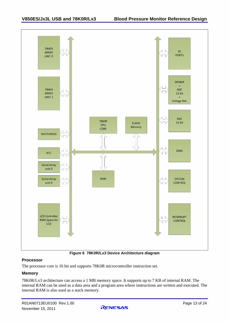
Figure 6 78K0R/Lx3 Device Architecture diagram
Processor The processor core is 16 bit and supports 78K0R microcontroller instruction set.
Memory 78K0R/Lx3 architecture can access a 1 MB memory space. It supports up to 7 KB of internal RAM. The internal RAM can be used as a data area and a program area where instructions are written and executed. The internal RAM is also used as a stack memory.
V850ES/Jx3L USB and 78K0R/Lx3 Blood Pressure Monitor Reference Design
R01AN0713EU0100 Rev.1.00 Page 14 of 24 November 15, 2011
Flash Memory
The 78K0R/Lx3 incorporates the flash memory to which a program can be written, erased, and overwritten while mounted on the board. 78K0R/Lx3 supports a maximum 128KB of program flash. Data can be written to flash memory using any of the following methods.
• Writing to flash memory by using flash memory programmer • Writing to flash memory by using external device (that Incorporates UART) • Self-programming
The 78K0R/Lx3 supports a security function that prohibits rewriting the user program written to the internal flash memory, so that the program cannot be changed by an unauthorized person
Timers The timer array unit has eight 16-bit timers. Each 16-bit timer is called a channel and can be used as an independent timer. In addition, two or more “channels” can be used to create a high-accuracy timer. Timer array unit has the following functions. By operating a channel independently, it can be used for the following purposes without being affected by the operation mode of other channels.
1. Interval timer Each timer of a unit can be used as a reference timer that generates an interrupt (INTTM0n) at fixed intervals.
2. Square wave output A toggle operation is performed each time INTTM0n interrupt is generated and a square wave with a duty factor of 50% is output from a timer output pin (TO0n).
3. External event counter Each timer of a unit can be used as an event counter that generates an interrupt when the number of the valid edges of a signal input to the timer input pin (TI0n) has reached a specific value.
4. Divider function (channel 0 only) A clock input from a timer input pin (TI00) is divided and output from an output pin (TO00).
5. Input pulse interval measurement Counting is started by the valid edge of a pulse signal input to a timer input pin (TI0n). The count value of the timer is captured at the valid edge of the next pulse. In this way, the interval of the input pulse can be measured.
6. Measurement of high-/low-level width of input signal Counting is started by a single edge of the signal input to the timer input pin (TI0n), and the count value is captured at the other edge. In this way, the high-level or low-level width of the input signal can be measured.
7. Delay counter Counting is started at the valid edge of the signal input to the timer input pin (TI0n), and an interrupt is generated after any delay period.
By using the combination of a master channel (a reference timer mainly controlling the cycle) and slave channels (timers operating according to the master channel); channels can be used for the following purposes.
1. One-shot pulse output Two channels are used as a set to generate a one-shot pulse with specified output timing and a specified pulse width.
2. PWM (Pulse Width Modulation) output Two channels are used as a set to generate a pulse with a specified period and a specified duty factor.
3. Multiple PWM (Pulse Width Modulation) output By extending the PWM function and using one master channel and two or more slave channels, up to seven types of PWM signals that have a specific period and a specified duty factor can be generated.
Ports The 78K0R/Lx3 microcontrollers are provided with digital I/O ports, which enable variety of control operations. Pin I/O buffer power supplies depend on the product. The power supply can be VDD or AVDD0 or AVDD1 or EVDD. In addition to the function as digital I/O ports, these ports have several alternate functions.
V850ES/Jx3L USB and 78K0R/Lx3 Blood Pressure Monitor Reference Design
R01AN0713EU0100 Rev.1.00 Page 15 of 24 November 15, 2011
Serial Interfaces Serial array unit 0 has four serial channels, and serial array unit 1 has two. Each channel can achieve 3-wire serial (CSI), UART, and simplified I2C communication. Simplified I2C does not support slave mode, arbitration loss detection and wait detection
Clock Output/Buzzer Output Controller USB Buzzer output is a function to output a square wave of buzzer frequency. One pin can be used to output a clock or buzzer sound. This can be used for adding audio alarm facility for the product.
BCD correction circuit The result of addition/subtraction of the BCD (binary-coded decimal) code and BCD code can be obtained as BCD code with this circuit.
Multiplier and Divider The multiplier and divider/multiply-accumulator has the following functions.
• 16 bits × 16 bits = 32 bits • 32 bits ÷ 32 bits = 32 bits, 32-bits remainder
ADC The Analog to digital converter has 12 bit resolution and supports 12 channels. It supports both single and continuous conversion modes. There are on chip operational amplifier (up to three) which can be used for input amplification and filtering before converting to digital signal. There is also an on board reference voltage generator which can be used by the ADC.
DAC 78K0R/Lx3 has on-chip Digital to analog converter with 12 bit resolution and supports 2 Channels. It supports both normal and real time conversion modes. In real time conversion mode, timers are used to generate the interrupt to transfer data to DAC for conversion.
LCD Controller / Driver 78K0R/Lx3 has on-chip LCD Controller driver with support for 31-54 segment signals and 8 common signals. It supports six display modes with 20 stage contrast adjustment.
V850ES/Jx3L USB and 78K0R/Lx3 Blood Pressure Monitor Reference Design
R01AN0713EU0100 Rev.1.00 Page 16 of 24 November 15, 2011
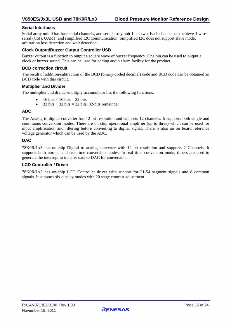
5. Reference Design Architecture Table 1 Requirements Table
Blood Pressure Monitor
Requirements
Relevance Renesas Device
V850ES/JG3-L
External Hardware
Renesas Device
78K0R/Lx3
External Hardware
Amplifier High None Required On Chip Analog Filter High None Required Required
ADC High 10 bit ADC 12 bit ADC Signal Processing High Multiplier Multiplier
Pump driver High None Required None Required DAC Medium 8 bit ,3uS R-2R 12 bit DAC
LCD Controller High None Required On Chip Connectivity Medium USB Wireless None USB/
Wireless
5.1 Hardware Architecture A typical implementation using Renesas V850ES/JG3-L device is shown in Figure 7. The cuff is inflated using a pump which is driven by V850ES/JG3-L device through a driver and will be deflated using a valve which is also controlled by the same device. The pressure transducer in the cuff is interfaced through an amplifier and a low pas filter before digitized by the V850ES ADC. The digitized values are processed to detect the mean pressure. The mean pressure is used to calculate systolic and diastolic blood pressure values. In ausculatory method the microphone in the cuff is interfaced to ADC using filter and amplifier. The DAC in V850ES/JG3-L is used to generate audio alarm if the readings exceed preset limits. The LCD display is controlled by an external LCD controller. The USB function in V850ES/Jg3-L is used to provide the connectivity solution.
Figure 7 High end Implementation Diagram
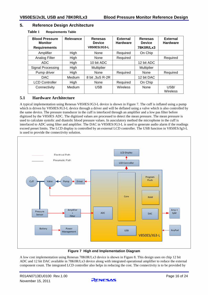
A low cost implementation using Renesas 78K0R/Lx3 device is shown in Figure 8. This design uses on chip 12 bit ADC and 12 bit DAC available in 78K0R/Lx3 device along with integrated operational amplifier to reduce the external component count. The integrated LCD controller also helps in reducing the cost. The connectivity is to be provided by
V850ES/Jx3L USB and 78K0R/Lx3 Blood Pressure Monitor Reference Design
R01AN0713EU0100 Rev.1.00 Page 17 of 24 November 15, 2011
an external USB function device or a wireless device. The motor control algorithms should be simplified in order to execute on this device.
Figure 8 Low cost implementation using 78K0R/Lx3 device
V850ES/Jx3L USB and 78K0R/Lx3 Blood Pressure Monitor Reference Design
R01AN0713EU0100 Rev.1.00 Page 18 of 24 November 15, 2011
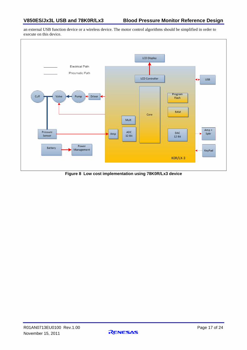
5.2 Software Architecture The software consists of drivers for pump, valve and audio ADC which in turn are used by middleware. The middleware consists of control algorithms for inflation and deflation of the cuff, audio signal processing for detecting pressure changes to measure systolic and calculate diastolic blood pressure. Data archiving and recall is to be implemented in the middleware which controls the onboard flash driver. The display driver controls the custom LCD including backlight to provide user display functionality. Power management is critical software which optimizes the resources to prolong the battery life. The communication driver provides the connectivity need of the device. The main blood pressure monitoring application implements the final user application
LCD Driver
Pump & valveDriver
Signal processing
ADC Driver
Power Manage
ment
USB driver
Data Archiving
Flash Driver
Hardware Abstraction
Control Algorithms
PressureSensordriver
ContinuaUSB Stack
Application
Figure 9 Software Architecture
V850ES/Jx3L USB and 78K0R/Lx3 Blood Pressure Monitor Reference Design
R01AN0713EU0100 Rev.1.00 Page 19 of 24 November 15, 2011
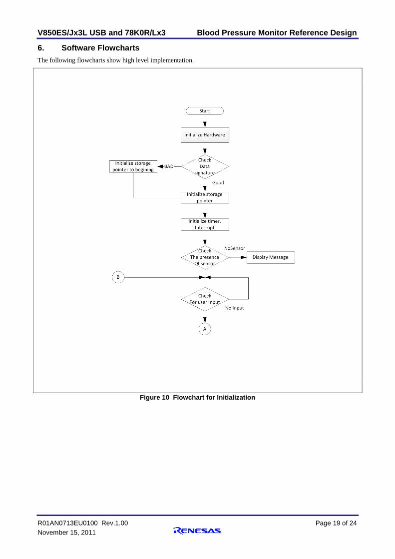
6. Software Flowcharts The following flowcharts show high level implementation.
Figure 10 Flowchart for Initialization
V850ES/Jx3L USB and 78K0R/Lx3 Blood Pressure Monitor Reference Design
R01AN0713EU0100 Rev.1.00 Page 20 of 24 November 15, 2011
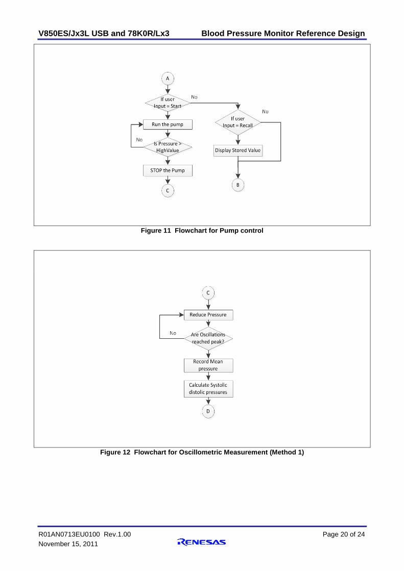
Figure 11 Flowchart for Pump control
Figure 12 Flowchart for Oscillometric Measurement (Method 1)
V850ES/Jx3L USB and 78K0R/Lx3 Blood Pressure Monitor Reference Design
R01AN0713EU0100 Rev.1.00 Page 21 of 24 November 15, 2011
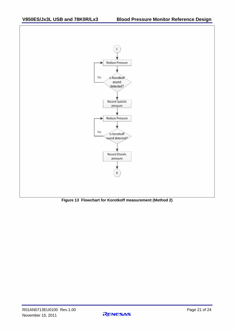
Figure 13 Flowchart for Korotkoff measurement (Method 2)
V850ES/Jx3L USB and 78K0R/Lx3 Blood Pressure Monitor Reference Design
R01AN0713EU0100 Rev.1.00 Page 22 of 24 November 15, 2011
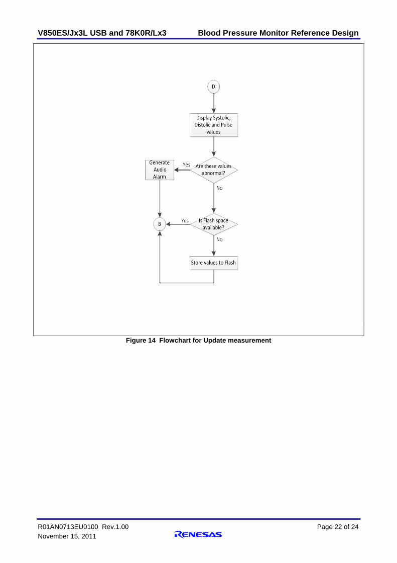
Figure 14 Flowchart for Update measurement
V850ES/Jx3L USB and 78K0R/Lx3 Blood Pressure Monitor Reference Design
R01AN0713EU0100 Rev.1.00 Page 23 of 24 November 15, 2011
Appendix A - References [1] Toshiyo Tamura , " Home Health care devices ", in Encyclopedia of Medical Devices and Instrumentation, Second edition, Vol. 3, Wiley-Interscience, 2006, pp. 526-527.
[2] Meir Nitzan, Automatic Noninvasive Measurement of Arterial Blood Pressure, IEEE Instrumentation & Measurement Magazine, February, 2011
[3] Wendy Van Moer, Lieve Lauwers, Danny Schoors, and Kurt Barbé, Linearizing Oscillometric Blood-Pressure Measurements: (Non)Sense?, IEEE Transactions on Instrumentation and Measurement, vol. 60, no. 4, April 2010
[4] Giancarlo Fortino,Valerio Giampà, PPG-based Methods for Non Invasive and Continuous Blood Pressure Measurement: an Overview and Development Issues in Body Sensor Networks, Medical Measurements and Applications Proceedings (MeMeA), 2010 IEEE International Workshop on, Ottawa,Canada, April 30 to May 1, 2010
[5] Milan Stork, Jiri Jilek, "Cuff Pressure Pulse Waveforms: Their Current and Prospective Application in Biomedical Instrumentation Home Health care devices ", in Biomedical Engineering Trends in Electronics, Communications and Software, InTech, 2011, pp. 207.
V850ES/Jx3L USB and 78K0R/Lx3 Blood Pressure Monitor Reference Design
R01AN0713EU0100 Rev.1.00 Page 24 of 24 November 15, 2011
Website and Support Renesas Electronics Website
http://www.renesas.com/ Inquiries
http://www.renesas.com/inquiry All trademarks and registered trademarks are the property of their respective owners.

A-1
Revision Record
Rev. Date Description Page Summary
1.00 November 15. 2011 — First edition issued

General Precautions in the Handling of MPU/MCU Products The following usage notes are applicable to all MPU/MCU products from Renesas. For detailed usage notes on the products covered by this manual, refer to the relevant sections of the manual. If the descriptions under General Precautions in the Handling of MPU/MCU Products and in the body of the manual differ from each other, the description in the body of the manual takes precedence.
1. Handling of Unused Pins Handle unused pins in accord with the directions given under Handling of Unused Pins in the manual. The input pins of CMOS products are generally in the high-impedance state. In operation with an
unused pin in the open-circuit state, extra electromagnetic noise is induced in the vicinity of LSI, an associated shoot-through current flows internally, and malfunctions occur due to the false recognition of the pin state as an input signal become possible. Unused pins should be handled as described under Handling of Unused Pins in the manual.
2. Processing at Power-on The state of the product is undefined at the moment when power is supplied. The states of internal circuits in the LSI are indeterminate and the states of register settings and
pins are undefined at the moment when power is supplied. In a finished product where the reset signal is applied to the external reset pin, the states of pins are not guaranteed from the moment when power is supplied until the reset process is completed. In a similar way, the states of pins in a product that is reset by an on-chip power-on reset function are not guaranteed from the moment when power is supplied until the power reaches the level at which resetting has been specified.
3. Prohibition of Access to Reserved Addresses Access to reserved addresses is prohibited. The reserved addresses are provided for the possible future expansion of functions. Do not access
these addresses; the correct operation of LSI is not guaranteed if they are accessed. 4. Clock Signals
After applying a reset, only release the reset line after the operating clock signal has become stable. When switching the clock signal during program execution, wait until the target clock signal has stabilized. When the clock signal is generated with an external resonator (or from an external oscillator)
during a reset, ensure that the reset line is only released after full stabilization of the clock signal. Moreover, when switching to a clock signal produced with an external resonator (or by an external oscillator) while program execution is in progress, wait until the target clock signal is stable.
5. Differences between Products Before changing from one product to another, i.e. to one with a different type number, confirm that the change will not lead to problems. The characteristics of MPU/MCU in the same group but having different type numbers may differ
because of the differences in internal memory capacity and layout pattern. When changing to products of different type numbers, implement a system-evaluation test for each of the products.