Embed Size (px)
Citation preview
7/28/2019 v6584r8
http://slidepdf.com/reader/full/v6584r8 1/4
Page 1 of 4
50 Hanover Road, Florham Park, New Jersey 07932 www.ascovalve.com
e MM All Rights Reserved. Printed in U.S.A.
Installation & Maintenance Instructions SERIES
Form No.V6584OPEN-FRAME, GENERAL PURPOSE, WATERTIGHT/EXPLOSIONPROOF SOLENOIDS
8003G
8202Gr
Ċ SERVICE NOTICE Ċ
ASCOr solenoid valves with design change letter G" or H" in the catalognumber (ex. 8210G 1) have an epoxy encapsulated ASCOr Red Hat IIr
solenoid. This solenoid replaces some of the solenoids with metal enclosuresand open-frame constructions. Follow these installation and maintenanceinstructions if your valve or operator uses this solenoid.
See separate instructions for basic valve.
DESCRIPTION
Catalog numbers 8003G and 8202G are epoxy encapsulated pull-typesolenoids. The green solenoid with lead wires and 1/2IĂconduit connection isdesigned to meet Enclosure Type 1-General Purpose, Type 2-Dripproof,Types 3 and 3S-Raintight, and Types 4 and 4X-Watertight. The blacksolenoid on catalog numbers prefixed EF" or EV" is designed to meetEnclosure Types 3 and 3S-Raintight, Types 4 and 4X-Watertight, Types 6and 6P-Submersible, Type 7 (A, B, C & D) Explosionproof Class I, Division1 Groups A, B, C, & D and Type 9 (E, F, & G)-Dust-Ignitionproof Class II,Division 1 Groups E, F & G. The Class II, Groups F & G Dust Locations
designation is not applicable for solenoids or solenoid valves used for steamservice or when a class H" solenoid is used. See Temperature Limitationssection for solenoid identification and nameplate/retainer for service. Wheninstalled just as a solenoid and not attached to an ASCO valve, the core hasa 0.250-28 UNF-2B tapped hole, 0.38 or 0.63 minimum full thread.
NOTE: Catalog number prefix EV" denotes stainless steel construction.
Catalog numbers 8202G1, 8202G3, 8202G5 and 8202G7 are epoxyencapsulated push-type, reverse-acting solenoids having the sameenclosure types as previously stated for Catalog numbers 8003G1 and8003G2.
Series 8003G and 8202G solenoids are available in:S Open-Frame Construction: The green solenoid may be supplied with
1/4I spade, screw or DIN terminals. (Refer to Figure 4)S Panel Mounted Construction: These solenoids are specifically designed
to be panel mounted by the customer through a panel having a .062 to .093
maximum wall thickness. Refer to Figure 1 and section on Installation of Panel Mounted Solenoid.
Optional Features For Type 1 - General Purpose
Construction Only
S Junction Box: This junction box construction meets Enclosure Types
2,3,3S,4, and 4X. Only solenoids with 1/4I spade or screw terminals may
have a junction box. The junction box provides a 1/2I conduit connection,grounding and spade or screw terminal connections within the junctionbox (See Figure 5).
S DIN Plug Connector Kit No.K236034:Ă Use this kit only for solenoids withDIN terminals. The DIN plug connector kit provides a two pole withgrounding contact DIN Type 43650 construction (See Figure 6).
OPERATION
Series 8003G - When the solenoid is energized, the core is drawn into the
solenoid base sub-assembly. IMPORTANT: When the solenoid isde-energized, the initial return force for the core, whether developed by
spring, pressure, or weight, must exert a minimum force to overcome
residual magnetism created by the solenoid. Minimum return force for AC
construction is 11 ounces, and 5 ounces for DC construction.
Series 8202G - When the solenoid is energized, the disc holder assemblyseats against the orifice. When the solenoid is de-energized , the disc holderassembly returns. IMPORTANT: Initial return force for the disc or discholder assembly, whether developed by spring, pressure, or weight, must
exert a minimum force to overcome residual magnetism created by thesolenoid. Minimum return force is 1 pound, 5 ounces.
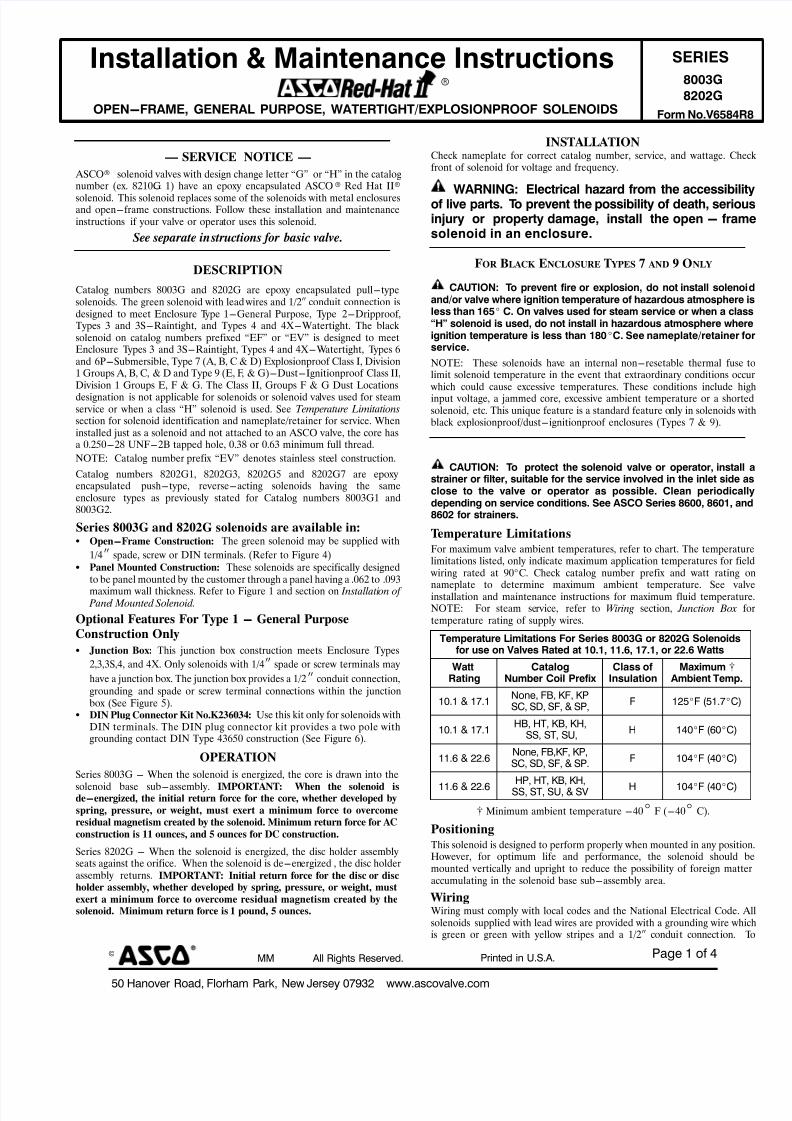
INSTALLATIONCheck nameplate for correct catalog number, service, and wattage. Chfront of solenoid for voltage and frequency.
WARNING: Electrical hazard from the accessibilof live parts. To prevent the possibility of death,Ăserioinjury or property damage, install the open - framsolenoid in an enclosure.
FOR BLACK ENCLOSURE T YPES 7 AND 9 ONLY
CAUTION: To prevent fire or explosion, do not install solenoand/or valve where ignition temperature of hazardous atmosphereless than 165_ C. On valves used for steam service or when a claH" solenoid is used, do not install in hazardous atmosphere wheignition temperature is less than 180_C. See nameplate/retainer service.
NOTE: These solenoids have an internal non-resetable thermal fuselimit solenoid temperature in the event that extraordinary conditions oc which could cause excessive temperatures. These conditions include hinput voltage, a jammed core, excessive ambient temperature or a shorsolenoid, etc. This unique feature is a standard feature only in solenoids wblack explosionproof/dust-ignitionproof enclosures (Types 7 & 9).
CAUTION: To protect the solenoid valve or operator, instastrainer or filter, suitable for the service involved in the inlet sideclose to the valve or operator as possible. Clean periodicadepending on service conditions. See ASCO Series 8600, 8601, a8602 for strainers.
Temperature Limitations
For maximum valve ambient temperatures, refer to chart. The temperatulimitations listed, only indicate maximum application temperatures for fi wiring rated at 90_C. Check catalog number prefix and watt rating
nameplate to determine maximum ambient temperature. See vainstallation and maintenance instructions for maximum fluid temperatuNOTE: For steam service, refer to Wiring section, Junction Boxtemperature rating of supply wires.
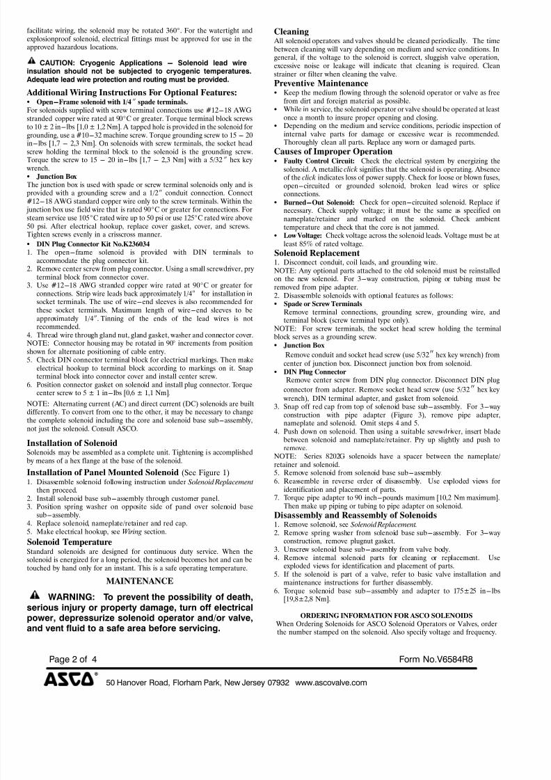
Temperature Limitations For Series 8003G or 8202G Solenoidsfor use on Valves Rated at 10.1, 11.6, 17.1, or 22.6 Watts
WattRating
CatalogNumber Coil Prefix
Class ofInsulation
Maximum [Ambient Temp
10.1 & 17.1None, FB, KF, KPSC, SD, SF, & SP,
F 125_F (51.7_C)
10.1 & 17.1HB, HT, KB, KH,
SS, ST, SU,H 140_F (60_C)
11.6 & 22.6None, FB,KF, KP,SC, SD, SF, & SP.
F 104_F (40_C)
11.6 & 22.6HP, HT, KB, KH,
SS, ST, SU, & SV H 104_F (40_C)
[ Minimum ambient temperature -40_ F (-40_ C).
Positioning
This solenoid is designed to perform properly when mounted in any positiHowever, for optimum life and performance, the solenoid should mounted vertically and upright to reduce the possibility of foreign mattaccumulating in the solenoid base sub-assembly area.
WiringWiring must comply with local codes and the National Electrical Code. solenoids supplied with lead wires are provided with a grounding wire whis green or green with yellow stripes and a 1/2I conduit connection.
7/28/2019 v6584r8
http://slidepdf.com/reader/full/v6584r8 2/4
50 Hanover Road, Florham Park, New Jersey 07932 www.ascovalve.com
Page 2 of 4 Form No.V6584R8
facilitate wiring, the solenoid may be rotated 360_. For the watertight andexplosionproof solenoid, electrical fittings must be approved for use in theapproved hazardous locations.
CAUTION: Cryogenic Applications - Solenoid lead wireinsulation should not be subjected to cryogenic temperatures.Adequate lead wire protection and routing must be provided.
Additional Wiring Instructions For Optional Features:S Open-Frame solenoid with 1/4I spade terminals.
For solenoids supplied with screw terminal connections use #12-18 AWGstranded copper wire rated at 90_C or greater. Torque terminal block screwsto 10 ± 2 in-lbs [1,0 ± 1,2 Nm]. A tapped hole is provided in the solenoid for
grounding, use a #10-32 machine screw. Torque grounding screw to 15 - 20in-lbs [1,7 - 2,3 Nm]. On solenoids with screw terminals, the socket headscrew holding the terminal block to the solenoid is the grounding screw.Torque the screw to 15 - 20 in-lbs [1,7 - 2,3 Nm] with a 5/32 I hex key wrench.S Junction Box
The junction box is used with spade or screw terminal solenoids only and isprovided with a grounding screw and a 1/2I conduit connection. Connect#12-18 AWG standard copper wire only to the screw terminals. Within the junction box use field wire that is rated 90_C or greater for connections. Forsteam service use 105_C rated wire up to 50 psi or use 125_C rated wire above50 psi. After electrical hookup, replace cover gasket, cover, and screws.Tighten screws evenly in a crisscross manner.
S DIN Plug Connector Kit No.K236034
1. The open-frame solenoid is provided with DIN terminals toaccommodate the plug connector kit.
2. Remove center screw from plug connector. Using a small screwdriver, pryterminal block from connector cover.
3. Use #12-18 AWG stranded copper wire rated at 90_C or greater forconnections. Strip wire leads back approximately 1/4I f or installation insocket terminals. The use of wire-end sleeves is also recommended forthese socket terminals. Maximum length of wire-end sleeves to beapproximately 1/4I.ĂTinning of the ends of the lead wires is notrecommended.
4. Thread wire through gland nut, gland gasket, washer and connector cover.NOTE: Connector housing may be rotated in 90_ increments from positionshown for alternate positioning of cable entry.5. Check DIN connector terminal block for electrical markings. Then make
electrical hookup to terminal block according to markings on it. Snapterminal block into connector cover and install center screw.
6. Position connector gasket on solenoid and install plug connector. Torquecenter screw to 5 ± 1 in-lbs [0,6 ± 1,1 Nm].
NOTE: Alternating current (AC) and direct current (DC) solenoids are built
differently. To convert from one to the other, it may be necessary to changethe complete solenoid including the core and solenoid base sub-assembly,not just the solenoid. Consult ASCO.
Installation of SolenoidSolenoids may be assembled as a complete unit. Tightening is accomplishedby means of a hex flange at the base of the solenoid.
Installation of Panel Mounted Solenoid (See Figure 1)1. Disassemble solenoid following instruction under Solenoid Replacement
then proceed .2. Install solenoid base sub-assembly through customer panel.3. Position spring washer on opposite side of panel over solenoid base
sub-assembly.4. Replace solenoid, nameplate/retainer and red cap.5. Make electrical hookup, see Wiring section.
Solenoid TemperatureStandard solenoids are designed for continuous duty service. When thesolenoid is energized for a long period, the solenoid becomes hot and can betouched by hand only for an instant. This is a safe operating temperature.
MAINTENANCE
WARNING: To prevent the possibility of death,serious injury or property damage, turn off electricalpower, depressurize solenoid operator and/or valve,and vent fluid to a safe area before servicing.
Cleaning All solenoid operators and valves should be cleaned periodically. The timebetween cleaning will vary depending on medium and service conditions. Ingeneral, if the voltage to the solenoid is correct, sluggish valve operation,excessive noise or leakage will indicate that cleaning is required. Cleanstrainer or filter when cleaning the valve.
Preventive MaintenanceS Keep the medium flowing through the solenoid operator or valve as free
from dirt and foreign material as possible.S While in service, the solenoid operator or valve should be operated at least
once a month to insure proper opening and closing.S Depending on the medium and service conditions, periodic inspection of
internal valve parts for damage or excessive wear is recommended.Thoroughly clean all parts. Replace any worn or damaged parts.
Causes of Improper OperationS Faulty Control Circuit: Check the electrical system by energizing the
solenoid. A metallic click signifies that the solenoid is operating. Absenceof the click indicates loss of power supply. Check for loose or blown fuses,open-circuited or grounded solenoid, broken lead wires or spliceconnections.
S Burned-Out Solenoid: Check for open-circuited solenoid. Replace if necessary. Check supply voltage; it must be the same as specified onnameplate/retainer and marked on the solenoid. Check ambienttemperature and check that the core is not jammed.
S Low Voltage: Check voltage across the solenoid leads. Voltage must be atleast 85% of rated voltage.
Solenoid Replacement1. Disconnect conduit, coil leads, and grounding wire.
NOTE: Any optional parts attached to the old solenoid must be reinstalledon the new solenoid. For 3-way construction, piping or tubing must beremoved from pipe adapter.2. Disassemble solenoids with optional features as follows:S Spade or Screw Terminals
Remove terminal connections, grounding screw, grounding wire, andterminal block (screw terminal type only).
NOTE: For screw terminals, the socket head screw holding the terminalblock serves as a grounding screw.S Junction Box
Remove conduit and socket head screw (use 5/32I hex key wrench) fromcenter of junction box. Disconnect junction box from solenoid.
S DIN Plug Connector
Remove center screw from DIN plug connector. Disconnect DIN plug
connector from adapter. Remove socket head screw (use 5/32I hex key wrench), DIN terminal adapter, and gasket from solenoid.
3. Snap off red cap from top of solenoid base sub-assembly. For 3-wayconstruction with pipe adapter (Figure 3), remove pipe adapter,nameplate and solenoid. Omit steps 4 and 5.
4. Push down on solenoid. Then using a suitable screwdriver, insert bladebetween solenoid and nameplate/retainer. Pry up slightly and push toremove.
NOTE: Series 8202G solenoids have a spacer between the nameplate/ retainer and solenoid.5. Remove solenoid from solenoid base sub-assembly.6. Reassemble in reverse order of disassembly. Use exploded views for
identification and placement of parts.7. Torque pipe adapter to 90 inch-pounds maximum [10,2 Nm maximum].
Then make up piping or tubing to pipe adapter on solenoid.
Disassembly and Reassembly of Solenoids1. Remove solenoid, see Solenoid Replacement.2. Remove spring washer from solenoid base sub-assembly. For 3-way
construction, remove plugnut gasket.3. Unscrew solenoid base sub-assembly from valve body.4. Remove internal solenoid parts for cleaning or replacement. Use
exploded views for identification and placement of parts.5. If the solenoid is part of a valve, refer to basic valve installation and
maintenance instructions for further disassembly.6. Torque solenoid base sub-assembly and adapter to 175±25 in-lbs
[19,8±2,8 Nm].
ORDERING INFORMATION FOR ASCO SOLENOIDS
When Ordering Solenoids for ASCO Solenoid Operators or Valves, orderthe number stamped on the solenoid. Also specify voltage and frequency.
7/28/2019 v6584r8
http://slidepdf.com/reader/full/v6584r8 3/4
50 Hanover Road, Florham Park, New Jersey 07932 www.ascovalve.com
Page 3 of 4Form No.V6584R8
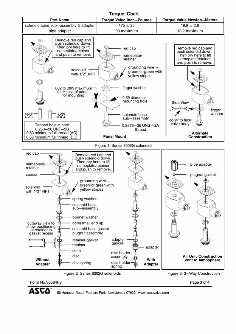
Torque Chart
Part Name Torque Value Inch-Pounds Torque Value Newton-Meters
solenoid base sub-assembly & adapter 175 ± 25 19,8 ± 2,8
pipe adapter 90 maximum 10,2 maximum
nameplate/
core
(AC) (DC)solenoid basesub-assembly
0.9375-26 UNS -2Athread
core
red cap
finger
Tapped hole in core0.250-28 UNF-2B
retainer
.062 to .093 maximumthickness of panel
for mounting0.69 diametermounting hole
push solenoid down.Then pry here to liftnameplate/retainer
AlternateConstructionPanel Mount0.38 minimum full thread (DC)
0.63 minimum full thread (AC)
Remove red cap and
push solenoid down.Then pry here to lift
nameplate/retainer
Remove red cap and
and push to remove.
and push to remove.
washe
finger washer
solenoidwith 1/2I NPT
grounding wire -green or green withyellow stripes
collar to facevalve body
Side View
Figure 1. Series 8003G solenoids
pipe adapter
plugnut gasket
plugnut assembly
solenoid base gasket
core(small end up)
retainer gasket
retainer
stem
disc
disc spring
bonnet washer
cutaway view toshow positioning
of retainer in
gasket recess
disc holder
adapter
adaptergasket
disc holderassembly
spring
solenoid basesub-assembly
nameplate/retainer
red cap
Air Only Construction Vent to AtmosphereWith
spacer
push solenoid down.Then pry here to liftnameplate/retainer
Remove red cap and
AdapterWithoutAdapter
and push to remove.
spring washer
grounding wire -green or green withyellow stripes
solenoidwith 1/2I NPT
Figure 2. Series 8202G solenoids Figure 3. 3-Way Construction
7/28/2019 v6584r8
http://slidepdf.com/reader/full/v6584r8 4/4
50 Hanover Road, Florham Park, New Jersey 07932 www.ascovalve.com
Page 4 of 4 Form No.V6584R8
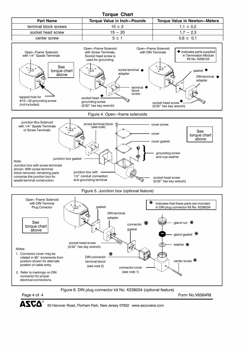
Torque Chart
Part Name Torque Value in Inch-Pounds Torque Value in Newton-Meters
terminal block screws 10 ± 2 1,1 ± 0,2
socket head screw 15 - 20 1,7 - 2,3
center screw 5 ± 1 0,6 ± 0,1
screw terminaladapter
gasket
DIN terminaladapter
socket head screw
socket headgrounding screw
Open-Frame SolenoidOpen-Frame Solenoid Open-Frame Solenoidwith Screw Terminals.Socket head screw is
used for grounding.
with DIN Terminals
tapped hole for#10-32 grounding screw(not included)
Seetorque chart
above
terminalblockscrew
with 1/4I Spade Terminals
(5/32I hex key wrench) (5/32I hex key wrench)
Indicates parts suppliedin Termination Module
Kit No. K256104
z
z
z
z
z
z
z
Figure 4. Open-frame solenoids
cover screw
cover gasket
cover
junction box gasket
junction box with
and grounding terminalsocket head screw
screw terminal block(see note)
grounding screwand cup washer
Junction Box Solenoid
Note:
Junction box with screw terminalsshown. With screw terminalblock removed, remaining partscomprise the junction box forspade terminal construction.
Seetorque chart
above
or Screw Terminals
(5/32I hex key wrench)
1/2I conduit connection
with 1/4I Spade Terminals
Figure 5. Junction box (optional feature)
gland nut
gland gasket
washersocket head screw
gasket
DIN terminal
connector
connector cover
center screw
adapter
gasket
(see note 1)
DIN connector
terminal block
(see note 2)
Indicates that these parts are includedOpen-Frame Solenoid
with DIN Terminal
Notes:
1. Connector cover may be
position shown for alternateposition of cable entry.
2. Refer to markings on DINconnector for properelectrical connections.
in DIN plug connector Kit No. K236034
Seetorque chart
above
Plug Conector
(5/32I hex key wrench)
rotated in 90_ increments from
Figure 6. DIN plug connector kit No. K236034 (optional feature)


