Embed Size (px)
Citation preview

OPERATOR`S, INSTALLATION AND MAINTENANCE MANUAL
V 503AP PROPELLER
P/N 073-8912.7
Edition: May 22, 1998
Civil Aviation Authority CZ approved
Reprint: October 10, 2003
Manufacturer: AVIA PROPELLER Ltd. Beranových 666 199 00 Praha - Letňany CZECH REPUBLIC
Tel.: (+420) 296 336 530 Fax.: (+420) 296 336 519 E-mail: [email protected] http://www.aviapropeller.cz

Operator´s Installation and Maintenance Manual of the V 503AP Propeller
Page: 2 May 22, 1998
This page is intentionally left blanc.

Operator´s Installation and Maintenance Manual of the V 503AP Propeller
May 22, 1998 Page:
3
Dear user:
You have purchased the propeller V 503AP. The propeller is a clockwise rotation,
automatic one, having the interchangeable blades made of duraluminium. During the
operation the propeller keeps the optimum RPM of the engine, according to its power upon
the all regimes of flight, in the range of air speeds common for sport and tourist flying. The
propeller operates without any pilot intervention. The propeller design is based on successful
left-hand rotation V 503A propeller. The propeller guarantees the safe and reliable operation
at maximum application of the flight performance.
Before introducing the propeller into regular operation, we recommend you to read
this manual carefully. The accurate respecting the principles stated here, it is an assumption
for your satisfaction with V 503AP propeller.
AVIA PROPELLER Ltd.

Operator´s Installation and Maintenance Manual of the V 503AP Propeller
Page: 4 May 22, 1998
This page is intentionally left blanc.

Operator´s Installation and Maintenance Manual of the V 503AP Propeller
May 22, 1998 Page:
5
SUMMARY OF VALID PAGES
Part Page Date Part Page Date Front page 1 May 22, 1998 2 May 22, 1998 Instruction for 28 May 22, 1998 Introduction 3 May 22, 1998 operational checking 29 May 22, 1998 4 May 22, 1998 the propeller 30 May 22, 1998 Summary of valid pages 5 May 22, 1998 Propeller care and 31 May 22, 1998 6 May 22, 1998 inspections 32 May 22, 1998 33 May 22, 1998 List of bulletins 7 May 22, 1998 8 May 22, 1998 Remedy of defects 34 May 22, 1998 35 May 22, 1998 Content 9 May 22, 1998 36 May 22, 1998 37 May 22, 1998 List of figures 10 May 22, 1998 38 May 22, 1998 39 May 22, 1998 Introductory information 11 May 22, 1998 40 May 22, 1998 12 May 22, 1998 13 May 22, 1998 Instruction on replace- 41 May 22, 1998 ment of propeller parts 42 May 22, 1998 Propeller description 14 May 22, 1998 List of assembly tools 43 May 22, 1998 Propeller function and 15 May 22, 1998 44 May 22, 1998 control Instructions for 16 May 22, 1998 1. appendix Fig.21 May 22, 1998 unpacking, inspection 17 May 22, 1998 and propeller 18 May 22, 1998 2. appendix Fig.22 May 22, 1998 installation 19 May 22, 1998 20 May 22, 1998 21 May 22, 1998 22 May 22, 1998 23 May 22, 1998 24 May 22, 1998 25 May 22, 1998 26 May 22, 1998 27 May 22, 1998

Operator´s Installation and Maintenance Manual of the V 503AP Propeller
Page: 6 May 22, 1998
This page is intentionally left blanc.

Operator´s Installation and Maintenance Manual of the V 503AP Propeller
May 22, 1998 Page:
7
LIST OF THE BULLETINS ISSUED concerning this manual
(records of user)
Ser. Nr
Bulletin number a/b Concerns Remark
a - obligatory bulletin
b - information bulletin

Operator´s Installation and Maintenance Manual of the V 503AP Propeller
Page: 8 May 22, 1998
This page is intentionally left blanc.

Operator´s Installation and Maintenance Manual of the V 503AP Propeller
May 22, 1998 Page:
9
CONTENT
Chapter Page Chapter Page Content 9 7. Remedy of defects 34 List of figures 10 7-1 In general 34 7-2 Repair of covers and spinner 34 1. Introductory information 11 7-3 Repair of propeller blades 35 1-1 Definition and determination 11 7-4 Propeller vibrations 36 1-2 Nomenclature 11 7-5 Engine does not reach the 1-3 Basic technical data 12 prescribed RPM during engine test 36 1-4 Mass 12 7-6 Engine exceeds the prescribed 1-5 Recommended material consum. 12 RPM during engine test 37 7-7 Leakage of propeller hub 37 2. Propeller description 14 7-8 Leakage of spinner shaft 39 7-9 Propeller unreliable operation 3. Propeller function and control 15 in range of prescribed speeds 40 4. Instructions for unpacking, 8. Part replacement instruction 41 inspection and installation 16 8-1 In general 41 4-1 Propeller transport 16 8-2 Spinner vane replacement 41 4-2 Propeller unpacking 17 8-3 Propeller blade replacement 41 4-3 Removal of conservation 17 8-4 Spinner replacement 42 4-4 Propeller installation 18 8-5 Propeller cover replacement 42 4-5 Propeller removal 23 4-6 Tightening torque moments 25 9. List of assembly tools 43 5. Instruction for operational 1. appendix Fig.21 checking the propeller 28 5-1 Engine test 28 2. appendix Fig.22 5-2 Adjustment after engine test 28 5-3 Checking flight 28 5-4 Adjustment after checking flight 29 5-5 Instructions for operation 30 6. Propeller care and inspections 31 6-1 Guarantee 31 6-2 Limitation of the airworthiness 31 6-3 General care 31 6-4 Pre-flight inspection 31 6-5 Aft-operation inspection and care 32 6-6 Care after 10 hours of operation 32 6-7 Care after 200 hours of operation 32 6-8 Care when breaking operation 33

Operator´s Installation and Maintenance Manual of the V 503AP Propeller
Page: 10 May 22, 1998
LIST OF FIGURES
Fig. Nr Name Page
1 Transporting case for the V 503AP propeller 17
2 Situating the propeller after taking out from the transporting case 18
3 Propeller installation on the engine 19
4 Propeller blades installation 20
5 Filling the propeller hub with oil 21
6 Checking the oil amount 22
7 Order of tightening the bolts of propeller cover 22
8 Spinner installation 23
9 Removal of the front propeller cover 24
10 Moment wrench application 26
11 Releasing 27
12 Adjustment of the spring prestress of the propeller
servomechanism
29
13 Repair of the damaged blade 35
14 Leakage off the closing screw 37
15 Replacement of the packing ring 38
16 Leakage off outer ring and blade bushing 39
17 Leakage around the shaft of the pump 39
18 Tolerance band of the V 503AP propeller installed on the
CESSNA 172 aircraft
40
19 Facility for static balancing the propeller 41
20 Assembly tools for the V 503AP propeller, bag for set „A“ 43
21 Propeller V 503AP cross section 1 appendix
22 Tightening torque moments 2 appendix

Operator´s Installation and Maintenance Manual of the V 503AP Propeller
May 22, 1998 Page:
11
1. Introductory information 1-1 Definition and determination
This manual offers the operational and service instructions for handling the two-
blade automatic clockwise propeller V 503AP. The propeller is intended for the general
aviation aircraft equipped with piston engines. The propeller is fully automatic, it means, that
it does not need any pilot intervention for the operation. The optimum engine RPM are kept
in dependence upon its performance at all regimes of flight and in the range of air speeds
common for sport and tourist flying up to the air speed for 194 knots. The propeller
guarantees the reliable operation at maximum simplicity of service and common
maintenance paid by the user. This propeller has been manufactured for you by firm:
AVIA - PROPELLER Ltd Beranových 666 199 00 Praha – Letňany Czech Republic
Phone: Fax.: E-mail: http:
(+420) 296 336 530 (+420) 296 336 519 [email protected] //www.aviapropeller.cz
1-2 Nomenclature
Here are given the data, which are not quite common in the aeronautical
terminology and they refer to this propeller.
P r o p e l l e r h u b - it is a major assembly of the propeller without propeller blades and
propeller cover. It consists of the propeller barrel, propeller blades seating and its
servomechanism.
S e r v o m e c h a n i s m - it is an individual propeller assembly, which contains the piston
with gear pump and spring with a device for adjusting the RPM.
S p i n n e r - it is a cover with two stages of freedom, equipped with blades (there is a
possibility for rotation and shifting). The spinner serves for driving the gear pump of
servomechanism (rotation) and at the same time it is a regulation sensor for RPM control (it
is shifted proportionally to the air speed).
M i n i m u m p i t c h - it is a minimum angle of propeller blades setting on the control
section, on which the propeller can be set. Its magnitude is determined by mechanical stop
arranged in the propeller servomechanism.
M a x i m u m p i t c h - it is a maximum angle of the propeller blades setting on the control
section, for which the propeller can be set. Its magnitude is determined by mechanical stop
in the propeller servomechanism and it is settled in accordance with a maximum air speed
of the aircraft.

Operator´s Installation and Maintenance Manual of the V 503AP Propeller
Page: 12 May 22, 1998
R a n g e o f t h e p r o p e l l e r b l a d e s s e t t i n g - it is a difference of propeller blades
angles between the stops for maximum and minimum pitch.
CAA CR - it is an abbreviation of the title „Civil Aviation Authority of Czech Republic“
1-3 Basic technical data
Propeller type variable-pitch in flight Way of blades setting hydraulic, autonomous Way of propeller function tractor-type Way of servomechanism function single acting Number of blades 2 Propeller diameter max. 75 in Range of blades setting 14° Sense of rotation clockwise Polar mass inertia moment Ip= 17.08 in lb s2 Max. propeller RPM 2750 rpm Max. short-time RPM 3025 rpm Max. absorbed shaft power 120 kW Engine flange SAE No. 2 (AS 127D) Dimensions of fixing bolts 7/16’’ - 20 UNF - 3A Working liquid AERO Shell Turbine Oil 3SP Transport box size 13.8 x 17.7 x 39 in Operation in the ice accretion conditions is prohibited Aerobatic Operation and spin under full - throttle is prohibited.
1-4 Mass
Mass of dry propeller 70.4 lb Mass of oil filling 1.98 ÷ 2.5 lb Mass of „A“ tool set 8.8 lb Mass of propeller hub 37 lb Mass of propeller blade 10.1 lb Mass of propeller cover 7.056 lb 1-5 Recommended material consumed
Specification Material Producer Remark OK-2A (KONKOR 101) conservation oil Benzina a.s.,
Korytná 47, 100 33 Praha 10, CR
conservation
Aero Shell -Ensis Fluid SDC
conservation Shell Czech Republic, a.s. Na Strži 63, 140 62 Praha 4, CR
conservation
Aero Shell Turbine Oil 3SP
oil Shell Czech Republic, a.s. Na Strži 63, 140 62 Praha 4, CR
working oil
Aero Shell 100 oil Shell Czech Republic, a.s. Na Strži 63,
for assembly

Operator´s Installation and Maintenance Manual of the V 503AP Propeller
May 22, 1998 Page:
13
140 62 Praha 4, CR
PM-G3 graphite plastic grease
Benzina, a.s., Korytná 47, 100 33 Praha10, CR
threads lubrication
BT-140/200 ČSN 65 6541
petroleum spirit cleaning the metal surfaces
AMS 3160 petrol solvent cleaning the metal surfaces
Cleanfit 7065 cleaning Loctite cleaning the metal surfaces
Operator´s Installation and Maintenance Manual of the V 503AP Propeller
Page: 14 May 22, 1998
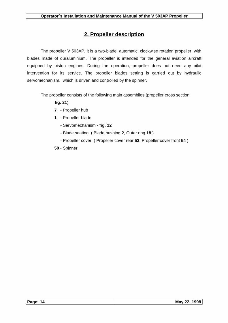
2. Propeller description The propeller V 503AP, it is a two-blade, automatic, clockwise rotation propeller, with
blades made of duraluminium. The propeller is intended for the general aviation aircraft
equipped by piston engines. During the operation, propeller does not need any pilot
intervention for its service. The propeller blades setting is carried out by hydraulic
servomechanism, which is driven and controlled by the spinner.
The propeller consists of the following main assemblies (propeller cross section
fig. 21):
7 - Propeller hub
1 - Propeller blade
- Servomechanism - fig. 12
- Blade seating ( Blade bushing 2, Outer ring 18 )
- Propeller cover ( Propeller cover rear 53, Propeller cover front 54 )
50 - Spinner
Operator´s Installation and Maintenance Manual of the V 503AP Propeller
May 22, 1998 Page:
15
3. Propeller function and control
The propeller does not need any pilot intervention for the function. The energy
needed for the blades setting in flight is gained from the flowing air, which by turning the
spinner drives the gear pump of the servomechanism and in dependence upon the air
speed sets the blades of propeller on the high angle of incidence. The blades setting on the
lower angles, it is carried out by forces caused by torque moment of the propeller blades.
The pressure oil delivery from the gear pump, it is carried out by the gate valve, position of
which depends upon the forward speed of the aircraft (pressing the spinner). Thus, the
propeller can be considered as fully autonomous element with open circuit and with a
correction on the forward speed.
Constructional design of the propeller is solved in such away, that the spinner is
fixed with a gate valve, which is installed in the propeller servomechanism, having there the
shift and rotation seating. The axial force is acting on the spinner in the flight and it is kept in
equilibrium through radial ball bearing by the force of spring. The torque aerodynamic
moment drives the gear pump of servomechanism, which is pumping off continuously the oil
from the space behind the piston to the space in front of the piston, and the excess of the oil
is bypassed through the holes in the gate valve back into the propeller hub. In case of
increase of the aircraft forward speed, there also increases the axial force acting on the
spinner, what causes the pressing of the spring and the gate valve is shifted further inside
the servomechanism. The releasing holes in the gate valve are covered and the oil pumped
now into the space in front of the piston is shifting the piston, until the holes in gate valve are
opened in such an extend, that the oil pressure be in equilibrium with a force caused by
torque moment of the propeller blades. When decreasing the forward speed of the aircraft,
there will take place the blade setting cycle in vice versa.
The V 503AP propeller is operating in the described way, beginning from the
forward speed of the aircraft about 43.2 knots. At lower speeds and during the take-off the
propeller functions as a fixed propeller. When changing the gas throttle, at constant air
speed of the aircraft, the propeller also functions as a fixed pitch propeller and the RPM are
varying according to the throttling characteristic of the engine.

Operator´s Installation and Maintenance Manual of the V 503AP Propeller
Page: 16 May 22, 1998
4. Instructions for unpacking, taking over inspection
and installation of the propeller 4-1 Propeller transport
For the transport of the propeller, its loose parts, spare parts and bag with
instrument, it is used the transporting case according to fig. 1. The case contains the
following parts:
Serial number
Name Remarks
1 Transporting case 2 Inlays 3 Parts for the propeller hub fastening 4 Parts for the windmill fastening 5 Bag with a tool of set „A“ 6 Box for the loose and spare parts
Transporting case intended for transport of the propeller complies with
requirements given in standard ČSN 77 0105. The propeller parts must be secured in the
transporting case against the mechanical damage by means of the fixing system defined in
standard ČSN 77 0105. The propellers forwarded from the plant of supplier are subjects to
conservation process. Conservation terms are given in packing list, in propeller log and on
the transporting case. To each propeller it is inserted the packing list in such a way, that be
protected against the eventual humidity (bag of polyethylene). On the transport case, there is
positioned the nomenclature according to the standard ČSN 77 0050. The transport itself
can be carried out by the all forwarding means, in which the space of transportation is
protected against the direct effect of the external affects.

Operator´s Installation and Maintenance Manual of the V 503AP Propeller
May 22, 1998 Page:
17
Fig. 1 Transporting case for the V 503AP propeller
4-2 Propeller unpacking
After opening the transporting case at first carry out the taking over inspection of the
parts supplied. The supply must contain all items, which are stated in the packing list, which
is inserted to each propeller. Remove the propeller blades, loose the windmill fastening nut
and remove the windmill. After the four nuts loosing, remove the propeller hub.
The individual assemblies, i.e. propeller blades, propeller hub and spinner, are to be
put on the clean auxiliary table. After removal of the protecting packing prepare the all parts
for removal of conservation. Read the propeller documentation, i.e. propeller log and
operation and technical manual. Prepare the bag with instrument for making the propeller
installation on the engine. The transporting case is to be situated in the storage room for a
future application, in order to protect it against the effects of external conditions.
4-3 Removal of propeller conservation
Wipe out the parts to be dry. The thin conservation layer on the propeller surface it is
not to be considered as a defect. The full removal of the conserving means from the
propeller surface carry out by wiping it by duster and recommended means. The frontal
surfaces of the engine flanges, propeller flanges and insertions Nr 65 fig. 3 and the
cylindrical root surfaces of the blades Nr 1 fig. 21 must be absolutely dry. Also the threads of
the bolts Nr 10 (fig. 3) and Nr 4 and nuts Nr 5 (fig. 21), must not contain the conservation
oil. (The steel ring on the blade cover with a thin layer of conservation grease).

Operator´s Installation and Maintenance Manual of the V 503AP Propeller
Page: 18 May 22, 1998
WARNING:
When removing the conservation layer be sure, that the degreasing agent did not
enter the space of propeller with packing, it could cause the swelling up the packing rings.
During the work it is forbidden to eat, drink and smoke.
4-4 Propeller installation
4-4.1 Taking out the propeller hub
From the propeller head, see figure Nr 2 „Situating the propeller after its taking out
from the transportation case“, remove the covering lid Nr 63 after loosening the 2 bolts
Nr 61 and from the propeller blades bushings take out the covering lids Nr 71 (Cleaning the
surfaces carry out in accordance with a previous paragraph).
Fig. 2
Situating the propeller after taking out from the transportation case
4-4.2 Installation of propeller on the engine
Installation details of the propeller are given by propeller and engine manufacturer
recommendations. For example the installation requirements for Lycoming engine, Series 0 -
320 are in accordance with following article:
At first clean the engine shaft and install carefully the packing ring Nr 72 there. Slide
on the propeller hub including the rear cover upon the engine shaft in such a way, that
between the propeller flange and engine flange be the insertion Nr 65, see figure 3. When
setting the propeller keep the prescribed position of the mark line „O“ on the propeller flange,
with respect to the mark line „TC“ made on the starting rim of the engine, view „P“, figure Nr

Operator´s Installation and Maintenance Manual of the V 503AP Propeller
May 22, 1998 Page:
19
3. The fixation itself carry out by means of 6 bolts Nr 10 and washers Nr 9. The bolts tighten
by torque moment 398.2 through 442.5 lb in. Torque moment is valid for the prescribed
tightening tool. It is necessary to keep the permitted range of the torque moment of
tightening. The couples of fixation bolts secure by locking wire (it is among the loose parts of
the propeller).
If the rear cover of propeller Nr 53, fig. 21 is not fixed to the propeller hub, carry out
this fixation in the following way:
Turn the rear cover Nr 53 in such a way, that the mark line „O“ on the rear propeller
cover (Fig. 3 view „O“), be in the same level as a mark line „O“ on the propeller flange, view
„P“. In this position fix the rear propeller cover by means of the bolts Nr 68, washers Nr 70
and nuts Nr 69. Tighten the bolts by torque moment 159.3 through 177 lb in.
WARNING:
The possibility of installation on other then above mentioned type of engine
must be approved by the propeller manufacturer.
Fig. 3 Propeller installation on the engine
4-4.3 Propeller blades installation

Operator´s Installation and Maintenance Manual of the V 503AP Propeller
Page: 20 May 22, 1998
Wipe out dry the internal part of the blade bushing Nr 2 (Fig. 21) and also the
cylindrical part and the thread of the propeller blade Nr 1. Slide on the rubber packing ring
Nr 6, provided in the loose parts, upon the propeller blade and screw in the propeller blade
into the blade bushing. For easy assembly cover the packing ring with a thin layer of grease.
After screwing the propeller blade into the bushing, the mark line on the blade must be
situated against the mark line on the conical surface of the blade bushing, Fig.4. The lower
end of the mark line „a“ must be at the upper edge of the blade bushing, or at maximum
1mm above its upper edge. Push the bushing to the recess on the upper edge of the blade
bushing Nr 2 and turn it in such a way, that the mark line on bushing „b“ be in accordance
with a mark line on the cylindrical part of the blade bushing recess „c“. In this position lock
the propeller blade by tightening the nut of the sleeve Nr 5 on the bolt Nr 4. Tighten the nut
by torque moment 531 through 575.2 lb in.
Against loosening, lock the nut with a splint 3x25 ČSN 02 1781.04. For tightening the
sleeve use the spanner Nr 8, adapter Nr 10 and the torque moment spanner Nr 1, Fig. 20.
Fig. 4 Propeller blade installation
4-4.4 Filling the propeller head with oil

Operator´s Installation and Maintenance Manual of the V 503AP Propeller
May 22, 1998 Page:
21
After propeller blades installation, turn the propeller into the position shown in
Fig. 5, loose the closing bolt Nr 11 and extract the washer Nr 12. Into the threaded hole in
the propeller hub insert the filling funnel and fill the propeller hub with 1 to 1.3 litres of the oil
Aero Shell Turbine Oil 3SP. The checking of the correct oil amount carry out by careful turning
the propeller, in order to let the oil to start draining of the propeller. If in this moment the
propeller blades are in position about 25° from the vertical axis, Fig. 6, the propeller contains
the correct amount of oil. Close the filling hole through tightening the screw Nr 11 over
washer Nr 12. Tighten the screw so, that be is possible to lock it by locking wire against
loosening. The wire is available in the loose parts of the propeller.
Fig. 5 Filling the propeller hub with oil

Operator´s Installation and Maintenance Manual of the V 503AP Propeller
Page: 22 May 22, 1998
Fig. 6 Checking the oil amount
4-4.5 Installation of the front cover of propeller
The surface of the rubber centring part on the front cover grease with a thin layer of
recommended grease and install the front propeller cover Nr 54, (Fig. 21) upon the cylinder
Nr 30 and upon the rear propeller cover Nr 53. The installation marks of the front and rear
covers must conform to each other. Fix the front cover to the rear propeller cover by means
of 10 bolts Nr 55 ( 8 bolts is included in the loose parts of the propeller and 2 bolts serve for
cover fixation during the transport). Tighten the bolts by screwdriver taken from the set of
assembly tools, which are supplied together with propeller in the assembly bag. The order of
bolts tightening is shown in figure 7.
Fig. 7 Order of tightening the bolts
of propeller cover 4-4.6 Spinner installation
Operator´s Installation and Maintenance Manual of the V 503AP Propeller
May 22, 1998 Page:
23
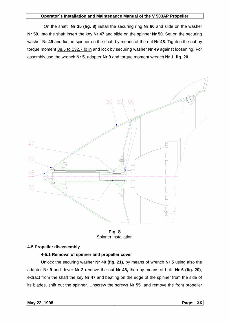
On the shaft Nr 35 (fig. 8) install the securing ring Nr 60 and slide on the washer
Nr 59. Into the shaft insert the key Nr 47 and slide on the spinner Nr 50. Set on the securing
washer Nr 49 and fix the spinner on the shaft by means of the nut Nr 48. Tighten the nut by
torque moment 88.5 to 132.7 lb in and lock by securing washer Nr 49 against loosening. For
assembly use the wrench Nr 5, adapter Nr 9 and torque moment wrench Nr 1, fig. 20.
Fig. 8 Spinner installation
4-5 Propeller disassembly
4-5.1 Removal of spinner and propeller cover
Unlock the securing washer Nr 49 (fig. 21), by means of wrench Nr 5 using also the
adapter Nr 9 and lever Nr 2 remove the nut Nr 48, then by means of bolt Nr 6 (fig. 20),
extract from the shaft the key Nr 47 and beating on the edge of the spinner from the side of
its blades, shift out the spinner. Unscrew the screws Nr 55 and remove the front propeller

Operator´s Installation and Maintenance Manual of the V 503AP Propeller
Page: 24 May 22, 1998
cover Nr 54. Remove the cover applying the slight force by screwdriver upon through
cuttings for propeller blades - see fig. 9.
Fig. 9
Removal of the front propeller cover
WARNING:
If you transport the propeller into the producer plant for repair or inspection, drain out the oil
off the propeller hub in accordance with a following paragraph.
4-5.2 Draining the oil
Remove the locking wire from the securing screw Nr 21, loose the bolt, loose the
cylinder cover Nr 44, cut off the locking wire and loose the closing screw Nr 11 (fig. 21),
then turn the propeller in such a way, that the filling throat in the hub points toward the
ground. Drain the oil into the ready container and then collect the oil into the common
container used for oil wastes. Set again and tighten the cover of the cylinder Nr 44, lock the
cover with a securing screw Nr 21, close the filling hole in the hub with closing screw Nr 11
over the packing washer Nr 12. Tighten the screw, but do not lock it.
4-5.3 Removal of the propeller blades

Operator´s Installation and Maintenance Manual of the V 503AP Propeller
May 22, 1998 Page:
25
Unlock the splint and loose the nuts Nr 5 (fig. 21) at both throats of the hub. For
releasing apply together with a socket wrench Nr 8 also the adapter Nr 10 and lever Nr 2
(fig. 20). Screw off the propeller blades Nr 1, slide in the protective lids Nr 71 into the
blades bushings and fix them by slight tightening the nuts Nr 5. The propeller blades situate
into the transporting case, or in another way securing to avoid their damage.
4-5.4 Dismantling the propeller hub
Remove the locking wire off the bolts Nr 10 (fig. 3), loose the bolts and together with
washers Nr 9, insertion Nr 65 and packing ring Nr 72, after propeller removal safe them for
further using. Set on the covering lid Nr 63 (fig. 2) upon the propeller shaft flange and fix it
by means of two bolts Nr 61 and washers Nr 62.
4-6 Tightening torque moments
4-6.1 Determination of the tightening moments
In the table fig. 22 - „Tightening moments“, there are given the tightening moments
of parts having the notation 1 to 5, which are recommended by production plant, when using
the assembly tools set „A“. In the following part of the table, there given the tightening
moments of parts with notation 6 to 10, mounting of which it is allowed to be carried out by
the service personnel only.
WARNING:
For making the assembly of the parts with notation 6 - 10 (fig. 20), there is
intended the bag with assembly tools set „B“.
4-6.2 Setting the tightening moment
Setting the required moment at torque moment wrench UMO 10 carry out by turning
the bolt with scale in the rear part of the wrench. The required value of the tightening
moment is set, if the moment magnitude is set against the cutting in the edge of the fixed
part of the moment wrench. The locking of the moment magnitude against its variation, it
can be done by arresting the setting bolt by means of the spanner Nr 14. Before setting the
another moment magnitude, loose this bolt again.
4-6.3 Application of the torque moment wrench
The universal torque moment wrench UMO 10 is to be used for tightening the
threaded joints, for which there is prescribed the moment of tightening.

Operator´s Installation and Maintenance Manual of the V 503AP Propeller
Page: 26 May 22, 1998
When using the assembly tools with notation Nr 8,3 and 15 (together with Nr 4),
always use the adapter VS N2, Nr 10. The adapter Nr 10 insert into the moment wrench
UMO 10 in such a way, that when making the tightening you can see the mark „R“ with an
arrow showing the direction of tightening, on the body of the moment wrench, fig.10. Arrest
the adapter Nr 10 by means of the Nr 14 wrench in the body of moment wrench. With a
wrench arranged in such a way, you can after setting the appropriate moments magnitudes,
apply the socket wrenches Nr 8,3 a 15 (together with Nr 4).
When using the assembly tools having the notation Nr 5 a 7, insert at first the adapter
Nr 9 into the moment wrench. The moment wrench UMO 10 with an adapter Nr 9 insert into
the hole of the wrench 5 or 7 in such a way, that during the tightening you can see the
marking „R“ with an arrow showing direction of tightening on the moment wrench. When
tightening take a care, that axis of the wrench be not deviated from the required position
more than by ±20°. In this case it would take place the decrease of accuracy of the
tightening moment setting.
Fig. 10 Moment wrench application
WARNING:
The setting of tightening moment magnitude carry out always from the lower value
to the higher one. When setting the tightening moment from the higher value to lower
one, loose at first the setting bolt under the requested value and then set on the final
value of the tightening moment.
After completing the work with a moment wrench, set always value of moment on
„0“ lb in.
4-6.4 Reaching the tightening moment
Tighten the bolted joint by means of prepared moment wrench up to the time point,
when you hear the audio signal (beat of the stop pin upon the inner wall of the tube), what
turns your attention on the fact of reaching the tightening moment requested.

Operator´s Installation and Maintenance Manual of the V 503AP Propeller
May 22, 1998 Page:
27
4-6.5 Releasing
For releasing of the all joints do not use the moment wrench, but make it by means of
the lever Nr 2 and appropriate adapters.
Fig.11 Releasing

Operator´s Installation and Maintenance Manual of the V 503AP Propeller
Page: 28 May 22, 1998
5. Instruction for operational checking the propeller
5-1 Engine test:
After checking the quality of the propeller installation on the engine and after
installation of the all covers, carry out the engine test of propeller. At full throttle, the take-off
RPM must be approximately by 100 rpm lower, than are the prescribed maximum take-off
RPM. It means, that for the Lycoming engine, series O-320, there must be the take-off
RPM in range 2600 ±30 rpm.
WARNING:
The propeller blades are on the stop of minimum angle during the engine test, thus
the propeller should behave as a fixed-pitch propeller. Nevertheless, in dependence
upon the servomechanism adjustment (prestress of the regulating spring), the air
flowing around the spinner can cause the changes of the spinner shifting a due to
that also the changes in propeller blades setting, what leads to minor changes in
take-off RPM.
5-2 Adjustment after engine test:
If the take-off RPM are not within a range of 2600 ±30 rpm, it is necessary to check
at first the setting of the propeller blades according to the point 4-4.3.
The marking line on the propeller blade must be accurately against the line on the
blade bushing.
This information is valid for maximum engine power, under the standard atmospheric
conditions, i.e. when having the engine power of 160 HP. When having the larger devi-ations
from the nominal power (by variation of engine power, by change of atmospheric conditions),
it is possible to change the setting of both blades by the same value.
The change of propeller blades setting by - 0,5° causes the change of take-off RPM
approximately by +45 rpm and vice versa, when changing the blades setting by +0,5°
the take-off RPM decrease approximately by 45 rpm (The change of angle by 0,5°
equals approximately to distance 0.012 in on the cylindrical part of the blade root)
5-3 Checking flight:
After making the engine test carry out the first checking flight. Reason for this flight,
it is to check the proper function of propeller and its adjustment.

Operator´s Installation and Maintenance Manual of the V 503AP Propeller
May 22, 1998 Page:
29
• The propeller is adjusted from the producer plant in such a respect, that the propeller
RPM at full throttle (maximum engine power) be during the whole checking flight in the
tolerance band according to the figure Nr 18.
In case, that RPM in the range of speeds 0 - 125 knots exceed the upper limit, or
they are under the lower limit of tolerances, carry out the adjustment of servomechanism in
accordance with a following paragraph.
5-4 Adjustment after checking flight
• Carry out removal of spinner and propeller cover in accordance with a point 4-5.1
• Loose the securing bolt Nr 21 (fig. 12), remove the securing ring Nr 60 (fig. 8 and 21)
and by means of the wrench Nr 7, adapter Nr 9 and lever Nr 2 and then carry out
dismantling the cylinder cover Nr 44. Change the prestress of the spring Nr 37 by means
of the nut Nr 39.
Change of spring prestress carried out by tightening the nut causes increase of the
RPM in flight, change of spring prestress carried out by loosing the nut causes the
decrease of RPM in flight.
After adjusting the spring prestress, carry out again the assembly of the
servomechanism parts, according to the fig. 12, if necessary, make the additional filling the
oil in order to have the prescribed amount in accordance with a paragraph 4-4.4.
Fig. 12
Adjustment of the spring prestress of the propeller servomechanism

Operator´s Installation and Maintenance Manual of the V 503AP Propeller
Page: 30 May 22, 1998
WARNING:
When dismantling the cylinder cover Nr 44, certain amount of oil is draining from the
propeller. In order to keep the proper propeller function, it is necessary to return this amount
of oil back. When adjusting, avoid turning the blades, it causes more oil to drain.
5-5 Instructions for operation:
We turn your attention on the fact, that this propeller differs in principle by its
function from the propeller of constant RPM (equipped with a regulator). An impulse needed
for blades setting, it is not initiated from the change of propeller (engine) RPM, but from the
change of forward speed.
In case, that the altitude characteristic of the engine has such a feature, that at
higher above sea level altitudes the propeller (engine) has a tendency for exceeding the
maximum take-off RPM, carry out the correction of the engine power at take-off by change
of gas throttle (decrease the maximum take-off power of the engine).
With respect to the control system and its regulating sensor - spinner, it can take
place, when having the deviated flights, mainly to the left side, at speeds above 88 knots,
the short-time exceeding the engine RPM to the maximum limit permitted. Under such
conditions we recommend you also to decrease the engine power.

Operator´s Installation and Maintenance Manual of the V 503AP Propeller
May 22, 1998 Page:
31
6. Propeller care and inspections 6-1 Guarantee
The commercial guarantee time for the individual purchaser is stated in the
purchase agreement closed between the producer and purchaser.
6-2 Limitation of the airworthiness
• In general „The section of limitation of the airworthiness has been certified by FAA
and it states the maintenance requested under the paragraph 43.16 and 91.163 of the
Federal aviation regulation, if not another alternative program has been certified by the
FAA authority“
• Service life of the propeller
Part Drawing number Technical life (hours)
Propeller V 503AP (073-0000) 6000
• Propeller overhauls
Part Drawing number Flight hours (time limitation)
Propeller V 503AP (073-0000) 1000 ( 5 years)
6-3 General care
The requirements put on the propeller care treatment are minimal, because the care
consists of regular inspections and prescribed checking. The lubrication of the movable parts
of the propeller mechanism is carried out automatically by the oil taken from the propeller oil
filling. If there is not carried out a new adjustment of the propeller, we recommend you to
carry out the oil replacement after 200 hours of operation or after 1 year from the last oil
replacement.
The oil replacement and the adjustment and inspections of the propeller record into
the log of propeller
6-4 Pre-flight inspection
Before the each flight, carry out the inspection of the propeller blades and propeller
cover. The reason for this inspection, it is to reveal the possible blade or cover damage and
also a leakage of the oil from the propeller hub. Check the easy turning of the spinner, state
of the spinner blades and their correct setting on the marks. If any defects are found, carry
out their remedies according to the chapter 7. Remedy of defects.
6-5 After operation inspection and care

Operator´s Installation and Maintenance Manual of the V 503AP Propeller
Page: 32 May 22, 1998
At the end of each flight day, check the condition of the propeller blades and the
spinner. The reason for it, it is again to reveal the possible damage of blades or spinner of
the propeller and also the leakage of the oil from propeller hub. Remedy the defects found,
according to the chapter 7. Remedy of defects.
The propeller blades, spinner and cover wash with a duster dipped in the water
with a detergent. The further care treatment carry out by wiping dry with a duster dipped in
the clean water. The all thus treated parts wipe dry by the duster.
WARNING:
When wiping the propeller blades be sure, that the treated blade is directed to
the ground. By this measure you prevent entering the washing solution into the
space of propeller with packing.
6-6 Care after 10 hours of operation
After the first 10 hours of the operation check the tightening of the nut Nr 48, fig.
21. The nut must be tightened by moment 88.5 to 132.7 lb in. After the tightening carry out
again its locking by means of locking washer Nr 49. Further, check the tightening of the six
bolts Nr 10. The bolts must be tightened by moment 398.2 to 442.5 lb in. After tightening,
carry out again the locking of bolts pairs by locking wire according to fig. 3.
The checking carried out record into the propeller log.
6-7 Care after 200 hours of operation
Carry out the following works:
6-7.1 Checking the setting of propeller blades.
The checking carry out in such a way, that each of two workers grasps one propeller blade
and they together set the propeller into the both limiting positions. There is to be checked the
easiness and smoothness of the resetting. After this checking the both blades must be set
on the minimum angle (take-off).
6-7.2 Checking the spinner.
Check the easy rotation of the spinner, condition of spinner blades and their correct setting
on the mark lines. For the evaluation of the defects found, proceed according to the chapter
7. Remedy of defects.
6-7.3 Oil replacement.
The draining of the oil filling carry out according to the 4-5.2. New filling of the oil into the
propeller carry out according to the paragraph 4-4.4.
Checking carried out record in the propeller log.
6-8 Care treatment when breaking the operation
Carry out the following works.

Operator´s Installation and Maintenance Manual of the V 503AP Propeller
May 22, 1998 Page:
33
6-8.1 when breaking the operation for a period less than 1 month
Wipe out the surfaces of propeller blades, propeller cover and spinner by dry duster. When
having the larger contamination, wash the propeller blades, spinner and cover by a duster
dipped into the water with a detergent. As a further care treatment carry out wiping by means
of duster dipped into the clean water. All parts treated in such a way wipe out dry by the
duster.
WARNING:
When wiping the propeller blades, pay attention, that the wiped blade be turned
to the ground. You will prevent the entering of the washing solution into the spaces
of the propeller with packing.
6-8.2 when breaking the operation for a period longer than 1 month but
shorter than 12 month.
Carry out care treatment according to the point 6-8.1, with a following conservation
of the propeller blades surface, propeller cover and spinner by means of the recommended
conservation means. The conservation carry out by the duster dipped into the conservation
oil. The oil must not run-down of the parts processed, thus carry out the conservation by
means of „half-dry“ duster. The conservation means must not enter the tightened propeller
space.
6-8.3 when eliminating the propeller off the operation for a period longer than
12 months
Remove the propeller off the engine according to the point 4-5, carry out the
treatment according to the point 6-8.2. Place the propeller into the packing and transporting
case, which were used for propeller supply from the producer plant. The propeller treated in
such a way store in such a place, where it is protected against the effects of external
conditions.
The data about the conservation performed according to the points 6-8.2 and 6-8.3
record into the propeller log.

Operator´s Installation and Maintenance Manual of the V 503AP Propeller
Page: 34 May 22, 1998
7. Remedy of defects
7-1 In general
During the propeller operation, it can occur the propeller damage or defect. In order
to avoid the elimination of the propeller from the operation, producer plant allows to carry out
some repair. In the following paragraphs, there is given the extent of the repairs permitted,
which can be carried out by the user.
7-2 Repair of covers and spinner
7-2.1 repair of the spinner
The repair of the deformed spinner Nr 50 can be carried out by beating-out with
help of mallet, using also the pad of the suitable shape, if the deformation does not exceed
in depth 0,2 in and its area does not exceed 0,9 in2, or if the repaired place is not in the
unapproachable part of the spinner. In this way it is allowed to be carried out maximum 2
repairs. When having the greater number of repairs required, or if the area to be repaired is
larger, replace the whole spinner in accordance with paragraph 8-4.
7-2.2 repair of the front cover
The repair of deformation of the front propeller cover Nr 54, it may be carried out through
beating-out by means of mallet and pad of suitable shape, if the depth of deformation is not
more than 0.2 in and its area is not larger than 0.9 in2. There are permitted at maximum 2
repairs. When having the higher number of repairs requested, or if the repaired area is
larger, replace the propeller cover Nr 53 and 54 in accordance with paragraph 8-5.
7-2.3 repair of the spinner blade
If you have found, that there is deformed the spinner blade Nr 51, it is possible to carry out
its straightening (beating-out) or to set it into the proper position marked on spinner by mark
line. In the proper position of the spinner blade, tighten the nut Nr 52 and lock it by means of
three digs-in. When making this locking, pay attention to prevent the spinner deformation.
7-2.4 repair of the rear cover
If there has been damaged the rear propeller cover Nr 53, the repair is not permitted. Carry
out the replacement of the both parts of the propeller cover Nr 53 a Nr 54, in accordance
with paragraph 8-5.
7-3 Repair of propeller blades
7-3.1 repair of damaged leading and trailing edges of the propeller blades

Operator´s Installation and Maintenance Manual of the V 503AP Propeller
May 22, 1998 Page:
35
If there are damages of leading edge from 0.008 in to 0.04 in, carry out the repair according
to the following procedure:
Clean the damaged edge by file or by grinding tool in such a way, that the width of
the grinding-out be 10 times larger than the depth of the damage and the depth of the repair
be in the range of 1 to 1.3 of the damage depth. Repair also the shape of the suction side
by „contraction“ of thickness in such a way, that the radius of the leading edge be the same
as it is on the neighbouring not damaged part of the blade, making the smooth change into
the 30% of the airfoil depth, see fig. 13. The repaired locality join smoothly to remaining
blade airfoil. The surface of the repaired place polish by the fine abrasive cloth Nr 250 to
300. Carry out checking by magnifying lens having the magnification 10. Check the repaired
place on cracks by means of colour defectoscopy. In the same way carry out the repair if
there is a local corrosion attack on the surface.
7-3.2 repair of damage on the suction and pressure side of the blade
If there appears the damage on suction or pressure side of the blade of the size from 0.008
to 0.028 in, carry out the repair in following way:
Clean the damaged suction or pressure side by means of the grinding tool in such a
way, that the width of the grinded place be 30 multiple of the depth of damage and the depth
of grinding be in the range 1.1 to 1.3 of the depth of damage. The repaired place join
smoothly to the neighbouring blade surface. Polish the surface of repaired place by means
of fine abrasive cloth of Nr 250 to 300.
Carry out checking by means of magnifying lens with a magnification 10. In case of
appropriate decision of the responsible technician of the user, the propeller must be static
balanced. The permitted unbalance - see point 7-4.
Fig. 13 Repair of the damaged blade

Operator´s Installation and Maintenance Manual of the V 503AP Propeller
Page: 36 May 22, 1998
The repair on the same radius of the suction and pressure side are not permitted. There are permitted maximum 5 repairs on the same blade from the radius 9.84 in, when the repaired places must be at least 3.94 in from each other. On the cylindrical part of the blade, there are not allowed repairs at all. When having the greater number of damages and if the blades are deformed from impact on the obstacle, send the propeller into the plant of producer for checking. The necessary repair carried out would be based upon the diagnostic checking of the important parts and their measuring.
WARNING: The repair of the bent propeller blades must not be done by user.
7-4 Propeller vibrations When user founds the increased vibrations during the operation, which did not occur before in the operation, proceed according to the following recommendations:
n check the setting of the propeller blades, on the stop of minimum angle n check the placing of balancing shims Nr 56 n remove the propeller and carry out new static balancing. (Permitted disbalance in
the horizontal position of blades is max. 0.354 lb in, in vertical position of blades max. 0,177 lb in. The balancing is to be carried out without the oil), fig. 19.
n check the engine - according to the engine instructions . 7-5 The engine does not reach the prescribed RPM during engine test
7-5.1 carry out the checking of blades setting
Engine Lycoming, series O-320, should have with a propeller the take-off RPM in the
range of 2600 ±30 rpm.
If the take-off RPM are not within the range 2600±30 rpm (fig. 18), check the setting of propeller blades according to the point 4-4.3. The mark line on the propeller blade must be accurately against the line on the blade
bushing.
This information is valid for the maximum engine power, at standard atmospheric conditions
(H=0 ISA), i.e. at engine power of 120 kW (160 HP). When having the larger deviations from
the nominal power (caused by the change of engine power or by change of the atmospheric
conditions), we allow to change the setting of both blades by the same value. The change of
the blades setting by - 0,5°, causes change of the take-off RPM approximately by +45 rpm
(Change of the angle by 0,5° equals approximately the distance of 0.012 in on the cylindrical
part of the blade).
7-5.2 check the engine speed indicator

Operator´s Installation and Maintenance Manual of the V 503AP Propeller
May 22, 1998 Page:
37
7-5.3 check the engine
7-6 Engine exceeds the prescribed RPM during engine test
7-6.1 check the blades setting according to the point 7-5.1
7-6.2 check the engine speed indicator
7-7 Leakage of propeller hub
In case of determination of the locality with the oil leakage during the propeller
operation, proceed in accordance with following instructions:
7-7.1 oil leakage in the region of closing screw Nr 11 (fig. 14)
Carry out removal of the spinner and propeller cover according to the point 4-5.1.
Replace the packing washer Nr 12. Tighten the screw Nr 11 so, that it be possible to carry
out locking by means of the locking wire against loosening. The locking wire is available
among the loose parts of the propeller.
Fig. 14 Leakage off the closing screw
7-7.2 oil leakage in the region of cylinder cover Nr 44
Carry out the removal of the spinner and propeller cover according to the point 4-
5.1, free the securing screw Nr 21 (fig. 12), remove the key from the shaft by means of the
bolt Nr 6 (fig. 20) and by means of the wrench Nr 7, lever Nr 2 with an adapter Nr 9 (fig. 20)
carry out dismantling of the cylinder cover Nr 44. Remove the old packing ring Nr 73, fig. 15.
Before installing the new packing ring, inspect the groove on the cylinder cover Nr 44 and
also inspect the opposite side packing cylindrical surface, if it is not contaminated. Clean the
surfaces dry. Insert the new packing ring into the groove through a thin thread. By pulling
this thread under the packing ring along the whole perimeter of the cylinder cover Nr 44
eliminate possible overturning of the packing ring. The outer surface of the packing ring and

Operator´s Installation and Maintenance Manual of the V 503AP Propeller
Page: 38 May 22, 1998
also the opposite side packing surface cover by recommended oil. Screw in back the
cylinder cover into the servomechanism according to the fig. 12. Tighten the cylinder cover
by moment 265.5 through 442.5 lb in by wrench Nr 7 and moment controller Nr 1 with
adapter Nr 9.
Fig. 15
Replacement of the packing ring
7-7.3 leakage of oil around the packing cuff Nr 58
Carry out removal of the spinner and propeller cover according to the point 4-5.1. At the
throat of the hub, where occurred the leakage of the oil in the region of packing cuff Nr 58,
unlock the splint and free the nut Nr 5 (fig. 21) by means of the socket wrench Nr 8 and the
lever Nr 2, together with adapter Nr 10, fig. 20. Screw-off the propeller blade Nr 1 and
situate it in such a way, to avoid its damage. Free the sleeve Nr 3 and slide it over the end of
the blade bushing Nr 2. Shift-off the ring Nr 57 and by means of the hook remove the old
packing cuff. Clean carefully the packing space, cover with a thin layer of the recommended
oil and set a new cuff in. When setting a new packing cuff, there must not be damaged the
packing knives. Upon the packing ring set again the ring Nr 57 and the sleeve Nr 3. The
face of the sleeve must be inserted behind the recess of the bushing Nr 2. Into the bushing
screw in the propeller blade Nr 1 and carry out the assembly according to the paragraph
4-4.3. The assembly of the propeller cover and spinner carry out according to the
paragraphs 4-4.5 and 4-4.6.
WARNING:

Operator´s Installation and Maintenance Manual of the V 503AP Propeller
May 22, 1998 Page:
39
When opening the sleeve use the special pliers for this purpose, or open it by means
of the pliers intended for securing rings. The gap in place of the sleeve cutting
must not be greater than 0.59 in.
In other cases of leakage:
7-7.4 oil leakage in the area of bolt Nr 29 - fig. 21
7-7.5 oil leakage in the area, outer ring - hub, see fig. 16, point „a“
7-7.6 oil leakage in the area of blade bushing see fig. 16, point „b“
the repair can be done only by service personnel or in the plant of producer.
Fig. 16
Leakage off outer ring and blade bushing
7-8 Leakage of spinner shaft
In case of determination of the oil leakage around the pump shaft, point „a“, fig. 17, the
repair is to be carried out only by service personnel or in the plant of producer.
Fig. 17
Leakage around the shaft of the pump
7-9 Propeller unreliable operation in range of prescribed speeds

Operator´s Installation and Maintenance Manual of the V 503AP Propeller
Page: 40 May 22, 1998
• The adjustment of the propeller is carried out in the plant of producer in such a way, that
the RPM at full throttle of gas (maximum engine power), be during the whole checking
flight in the tolerance band according to the figure Nr 18.
• In case of fluctuation of the RPM during the flight or if the propeller regulation does not
function properly, check the amount of oil according to the paragraph 4-4.4, fig. 6.
• In case, that RPM in the range of speed 0 - 125 knots exceed the upper tolerance limit or
if they are under the lower tolerance limit, carry out the adjustment of the propeller
servomechanism according to the following paragraph.
• Carry out disassembly of the spinner and propeller cover according to the point 4-5.1, free
the securing screw Nr 21 (fig. 12), remove the key from the shaft by means of bolt
Nr 6, (fig. 20) and by means of wrench Nr 7, adapter Nr 9 and lever Nr 2 (fig. 20) carry
out the removal of cylinder cover Nr 44. Change the prestress of spring Nr 37 by nut
Nr 39.
The change of the spring prestress made by nut tightening causes the increase of
RPM in flight, the change of the spring prestress made by nut releasing causes
decrease of RPM in flight.
The data about the repairs carried out according to the chapter 7, record into the
propeller log.
2560
2580
2600
2620
2640
2660
2680
2700
2720
2740
0 27 54 81 108 135 162
Speed of flight (knots)
RPM
RPMmaxim.minim.
Fig. 18 Tolerance band of RPM of the V 503AP propeller
installed on the Cessna 172 aircraft
8. Instruction on replacement of the propeller parts

Operator´s Installation and Maintenance Manual of the V 503AP Propeller
May 22, 1998 Page:
41
8-1 In general
In course of the propeller operation, it is allowed to replace some propeller parts
and assemblies according to the following instructions:
8-2 Spinner vane replacement
When it is necessary to replace the vane on the spinner, proceed in the following
way:
Carry out the spinner removal according to the point 4-5.1. Release the nut Nr 52, remove
the old vane Nr 51 and replace it with a new one. The cylindrical recess of the vane must be
easily sliding to the hole in the spinner. Set the vane into the position mark by line made on
the spinner and on the threaded part of the vane put the washer and tighten the nut Nr 52.
Lock it against releasing by three digs-in. During the locking pay the attention to the
prevention of spinner deformation. Carry out the spinner installation according to the point
4-4.6.
8-3 Propeller blades replacement
When replacing the propeller blades, replace both blades, i.e. the complete set. The
replacement can be carried out by service personnel only or in the plant of the producer.
The propeller must be again statically balanced, fig. 19.
The balancing shims Nr 56 place on the rear cover of propeller according to the section
A-A, fig. 21.
Fig. 19
Facility for static balancing the propeller.
8-4 Spinner replacement
When it is necessary to replace the complete spinner, proceed in the following way:

Operator´s Installation and Maintenance Manual of the V 503AP Propeller
Page: 42 May 22, 1998
Carry out the spinner removal according to the point 4-5.1. Check, if there is not lost the key
Nr 47 and carry out installation of the new spinner according to the point 4-4.6. It is not
necessary to carry out balancing the propeller, because the spinner is balanced already.
8-5 Propeller cover replacement
If there is necessary to replace the propeller cover, or some of its parts (Nr 54
propeller front cover, Nr 53 propeller rear cover), carry out the replacement of the both parts
at the same time. The replacement can be carried out by service personnel only.
The data about the replacements carried out according to the chapter 8 record into
the propeller log.
9. List of assembly tools

Operator´s Installation and Maintenance Manual of the V 503AP Propeller
May 22, 1998 Page:
43
Fig. 20 Assembly tools for the V 503AP propeller
Bag for set “A“
List of assembly tools for the V 503AP propeller - set „A“
Serial
number
Name Drawing number Pieces
1 Moment controller UMO-10 1 2 Lever 068-8110 1 3 Socket wrench 1217 1 4 Socket wrench 1113 1 5 Wrench body 073-7201 1 6 Bolt V 503-7201 1 7 Wrench (Nr 9) V 503-7202 1 8 Socket wrench 1219 1 9 Adapter 073-7203 1
10 Adapter VS N2 1 11 Nut eye-type bent wrench 13x14 1 12 Screwdriver DIN 5262 1 13 Internal wrench 8 1 14 Internal wrench 4 1 15 Reduction 1320 (1/2“ - 3/8“) 1

Operator´s Installation and Maintenance Manual of the V 503AP Propeller
Page: 44 May 22, 1998
This page is intentionally left blanc.

Operator´s Installation and Maintenance Manual of the V 503AP Propeller
Appendix 1 Page 1/3
APPENDIX 1 – Fig. 21
Cross Section of V 503AP Propeller
1 - Propeller Blade 41 - Bearing 2 - Blade Bushing 42 - Pin 3 - Sleeves 43 - Arresting Ball 4 - Sleeve Bolt 44 - Cylinder Cover 5 - Nut 45 - Packing 6 - Packing Ring 46 - Bushing 7 - Propeller Hub 47 - Key 8 - Lid 48 - Nut 9 - Washer 49 - Securing Washer
10 - Bolt 50 - Spinner 11 - Closing Screw 51 - Spinner Blade 12 - Packing Washer 52 - Nut 13 - Front Lid 53 - Propeller Cover Rear 14 - Piston Rod 54 - Propeller Cover Front 15 - Driver 55 - Screw 16 - Driver Guide 56 - Balancing Shim 17 - Securing Pin 57 - Ring 18 - Outer Ring 58 - Pecking Cuff 19 - Ball 59 - Washer 20 - Insertion 60 - Securing Ring 21 - Securing Screw 61 - Bolt 22 - Screw for Prestress 62 - Washer 23 - Support 63 - Covering Lid 24 - Securing Piece 64 - Flange 25 - Flange with Driving Pin 65 - Insertion 26 - Slide Block 66 - Bolt 27 - Washer 67 - Washer 28 - Securing Piece 68 - Bolt 29 - Bolt for Fixing the Servo 69 - Nut 30 - Cylinder 70 - Washer 31 - Piston 71 - Covering Lid (Fig 2) 32 - Pump Lid 72 - Packing Ring 33 - Pin 73 - Packing Ring (Fig. 13) 34 - Gear 35 - Pump Shaft 36 - Spring Guide 37 - Spring 38 - Support 39 - Nut 40 - Bearing Body

Operator´s Installation and Maintenance Manual of the V 503AP Propeller
Appendix 1 Page 2/3

Operator´s Installation and Maintenance Manual of the V 503AP Propeller
Appendix 1 Page 3/3

Operator´s Installation and Maintenance Manual of the V 503AP Propeller
Appendix 2 Page 1/3
APPENDIX 2 – Fig. 22
Tightening Moments
Valid for assembly tools supplied
Notation Wrench No. Tightening moment (lb.in)
1 3 398.2 – 442.5
2 5 88.5 – 132.7
3 8 531 – 575.2
4 7 265.5 – 442.5
5 4 and 11 159.3 – 177
6 106.2 – 123.9
7 885 – 1150.5 (1769.9 – 2212.4)
8 132.7 – 177
9 1592.9 – 1769.9 (3097.3 – 3539.8)
10
TOOLS SET “B”
(In brackets there are the actual moments of tightening)
17.7 – 26.5
WARNING: Set the required value of the tightening moment by means of the bolt situated in the rear part of the moment wrench. When the selected value of the tightening moment has been reached, you can hear the audio warning (clicking).

Operator´s Installation and Maintenance Manual of the V 503AP Propeller
Appendix 2 Page 2/3

Operator´s Installation and Maintenance Manual of the V 503AP Propeller
Appendix 2 Page 3/3