Embed Size (px)
Citation preview
It~sa /
3 9080 02753 9748 ,
V393.R46 UNITED STATES
EXPERIMENTAL MODEL BASIN
NAVY YARtD, WASHINGTON, D.C.
COLLAPSE BY INSTABILITY
OF rHIN CYLINDRICAL
UNDER EXTERNAL P
SHELLS
RESSURE
BY DWIGHT F. WINDENBURGAND
AFITHARLES TRILLINGth. 010CHARLES TRILLING
JUN 2 5 1976
JULY 1934
7- 1''r .. i•i • -- F." i "
REPORT No. 385
2
k
.7
I $,
1-., '
~
'It
I,!. - -'1~
-Ct. - 'K
L
COLLAPSE BY INSTABILITY OF THIN
CYLINDRICAL SHELLS UNDER EXTERNAL PRESSURE
byDwight F. Windenburg
andCharles Trilling
Reprint from
TRANSACTIONSof The American Socieyy of Mechanical Engineers
NOVEMBER, 1934VOL 56, NO. 11
Published by The American Society of Mechanical Engineers
U.S. Experimental Model Basin
Navy Yard, Washington, D.C.
Report No. 385
IYI ____ __ _ _
July 1934

NOW*,
Collapse by Instability of Tjin CylindricalShells Under External Pressure
By DWIGHT F. WINDENBURG' AND CHARLES TRILLING,' WASHINGTON, D. C.
This paper discusses the collapse by instability of thin-walled cylindricl vessels subjected to external pressure.The most important of the theoretical and empiricalformulas that apply to this subject are presented in a com-mon notation. A new and simple instability formula isdeveloped.
Three classes of tubes are considered: Tubes of infinitelength; tubes of finite length with uniform radial press-ure only; and tubes of finite length with both uniformradial and axial pressure. Collapsing pressures calcu-lated by the various formulas are presented in tabularform as a means of comparing the formulas.
The formulas are discussed briefly and checked againstthe results of tests conducted at the U. S. ExperimentalModel Basin for the Bureau of Construction and Repair,Navy Department.
This paper is a sequel to one previously published' as apart of the work of the A.S.M.E. Special Research Com-mittee on the Strength of Vessels Under External Pressure.
HE STRENGTH of a circular, cylindrical shell under ex-
ternal pressure depends upon its length-diameter and thick-ness-diameter ratios and upon the physical properties of the
material. Failure of the vessel may occur in either of two ways.A short vessel with relatively thick walls fails by stresses in thewalls reaching the yield point, while a long vessel with relativelythin walls fails by instability or buckling of the walls at stresseswhich may be considerably below the yield point. These typesof failure are analogous to the familiar column action: a short,thick column failing by "yield," and a long, thin column col-lapsing by "instability." The analogy to thin plates under com-
SAssistant Physicist, U. S. Experimental Model Basin, NavyYard, Washington, D. C. Mr. Windenburg was graduated from Cor-nell College, Mt. Vernon, Iowa, with the M.A. degree. He had twoyears of graduate work in physics and mathematics at the Universityof California. For three years he was head of the mathematics de-partment of the Polytechnic College of Engineering, Oakland, Calif.,and for two years head of the mathematics department of the LongBeach Junior College, Long Beach, Calif. Since January, 1929,he has been in his present position.
' Junior Physicist, U. S. Experimental Model Basin, Navy Yard,Washington, D. C. Mr. Trilling received the B.S. degree from theCollege of the City of New York, in 1929, and the M.A. degreefrom the George Washington University in 1934. Since December,1929, he has been in his present position, engaged in structuralresearch.
' "Strength of Thin Cylindrical Shells Under External Pressure."by H. E. Saunders and D. F. Windenburg, A.S.M.E. Trans., vol. 53,1931, paper APM-53-17a.
Contributed by the Applied Mechanics Division for presentationat the Annual Meeting, New York, N. Y., December 3 to 7, 1934, ofTa AMERICAN SocIETY OF MECHANICAL ENGINEERS.
Discussioq of this paper should be addressed to the Secretary,A.S.M.E., 29 West 39th Street, New York, N. Y., and will be accepteduntil January 10, 1935, for publication at a later date.
NoTE: Statements and opinions advanced in papers are to beunderstood as individual expressions of their authors, and not thoseof the Society.
All opinions or assertions contained in this paper are private onesof the authors and are not to be construed as official or reflecting theviews of the Navy Department or the Naval service at large.
pression is even closer. In all three cases, tubes, columns, andplates, there is an intermediate region between the regions of in-stability and yield.
In the present paper, only the region of instability is considered.Nevertheless, as in the case of columns, instability formulas canbe extended to the intermediate region by substituting the cor-rect value of the effective modulus of elasticity (1)' (2, p. 240) inthe formulas. Such an extension, however, requires an accuratestress-strain curve of the material, and the determination of col-lapsing pressure in this region is indirect and cumbersome.
The heads of a pressure vessel, if sufficiently close together,may exert considerable influence on the strength of the shell.Bulkheads or stiffening rings of adequate rigidity may be con-sidered equivalent to heads (3), (4). However, if the tube is rela-tively very long, the heads exert no appreciable influence on thecentral portion. The collapsing pressure of such a tube will bethe same as the collapsing pressure of a tube of infinite length.The minimum length of tube for which the strengthening in-fluence of the heads can be ignored is called the "critical length"(2, p. 226), (5, III, p. 68). The existence of such a critical lengthwas found experimentally by Carman (6) and Stewart (7) whomade many tests on long pipes and tubes,
INSTABILITY FORMULAS
The most important instability formulas published are pre-sented for the purpose of comparison in a common notation asfollows:
D -= diameter of tube'L = length of tubet - thickness of shellp = collapsing pressureE = modulus of elasticityA = Poisson's ration = number of lobes or waves in a complete circumferential
belt at the time of collapse.
Since the linear dimensions D, L, and t appear in all formulasonly as dimensionless ratios which are independent of the unitsin which these dimensions are expressed, p is given always in thesame units as E.
PIPES OR TUBES LONGER THAN CRITICAL LENGTH
Any tube longer than the critical length can be considered asa tube of infinite length since its collapsing pressure is inde-pendent of further increase in length. The following formulasapply to such tubes:
Bresse, Bryan (8), (9)
2Ep 2 E (t/D) ................. [A]
4 Numbers in parentheses correspond to references given at the enof the paper.
5 In all the theoretical formulas D is the diameter to the neutralaxis. Practically, for thin shells, the differences between outsidediameter, inside diameter, and diameter to the neutral axis arenegligible.
1141
Stewart, Carman and Carr (7), (10) (empirical and for steel tubesonly)
p = 50.2 X 10⁶ (t/D) ... . . . . . . . . . . . [B]
Formula [A] is the generally accepted formula for the col-lapsing pressure of an infinitely long thin tube. It differs fromthe formula of IAvy (11) for a ring of rectangular cross-section
p = 2E (tlD)'
only by the factor (1 - 0).Formula [B] has the same form as formula [A], but the con-
stant term is about 25 per cent smaller. The difference is due tothe fact that while formula [A] is for geometrically perfect tubesformula [B] represents the average collapsing pressure of a greatmany commercial steel tubes taken at random from stock.
PRESSURE VESSELS OR TUBEs SHORTER THAN THE CRITICALLENGTH
The formulas which follow apply to pressure vessels or tubesshorter than the critical length. The ends of the tubes are as-sumed to be simply supported, that is, free to approach each otherand free to rotate about the points of support. This ideal typeof end constraint "tends merely to maintain the circularity of thetube without restricting the slope of the tube walls" (5, I, p. 696).This condition is not entirely fulfilled in practise since there issome resistance to rotation at the points of support. However,there is probably very little fixation at stiffening rings because oftheir small torsional rigidity and because of the staggered natureof the bulges (3, Fig. 3). Any fixation makes for added safety.
The quantity n which appears in most instability formulas isnot an independent variable. It must be evaluated, when theformulas are applied to a given pressure vessel, by the con-dition that n is the integral number for which p is a minimum (2,p. 222). Methods of evaluating n other than by tedious trialand error substitutions are shown later.
e various instability formulas follow.
INSTABILITY FoRMULAS FOR TBES SHORTER THAN CRITICAL
LENGTH
Instability Formulas for Tubes Loaded With Radial Pressure Only.von Mises (12, Eq [B]) corrected:
1 [ n- ,n' + x, 2E
3 1 + n2-1 1 - )'
S2E(t/D)
(nI - 1) n2 +1(rD
where
p(2 - p)Xp - ( p) _ = P [3 + j + (1 - Al)p](1 - p),
X3 = p(1 +I) - p, I (1 + 2 ) + (1 - l)(1 - pjI)
1+ L p
n +1
von Mises (12, Eq [D]) corrected:
P -1 2n -1 -J" 2Ea- 1 - ,U2
OD
S 2E(t/D) [2)(nI-1) nI ()-L +1]. 2
I rD
von Mises, approximate Eq [D]:
1 + 2 E(t/D)I3 12L1 1- !,nsD) - 1
2E(t/D)
+ n[2. + I ].[trD / il i
Southwell (2):
P1 (n _ 1) 2E (t+D)I + 2E(t/D) [4]3 (D)1 - (n - 1)n2L
t.D/
Southwell (5, III), approximate hyperbola:
8 -V6 E (tLD)' [527 (1 - p')/' LID...........[5]
Instability Formulas for Tubes Loaded WithBothRadialandAzialPressure.
von Mises (13, Eq [61]):
p =[I {1 + (rD - 2InI + 1 2E (t/D)'3 2L 1 - A2
+ 2E(t/D) 1 61+ 2 /2L * ]2 ..... [6 ]n.D -1 n - 1-+2 2L
where
2jlz = 2 +X2 = [1 + (1 + IA)p][2 + (1-I)p]
f = 1 + X, = (1 - pp) 1 + (1 + 2u)p
(1- ') 1 + + ~pPP, X2, and X, are defined in formula [1].
Tokugawa (14): .
[ (rD 2 n(2n'-1) 2EP=j {[n + 2L -- D 1 i---i (t/ID)'
von Mises (13, Eq [71):3 P + )] -- (2D)L
2E(t/D) 1[.[ 2L)2 1] n 1+ *"t-I ~ ~ I2~ +ll 1 rD)2, ...... sna 2 D1 -1. -
( D 22Lvon Mises (13, Eq [71):
[ = n2 + (r)] E(t/D)I3 2L 1 - JA
+ 2E(t/D) [8
n2 - n+(L2+ 1] 1t (+ ....
I rD 22L
III
U. S. Experimental Model Basin:
2.42E (tiD)' 1'(1 ),I)' FL_ 0.45 (t/D), 9]
D
or, for p = 0.3,
2.60E(t/D)'/'p =f L. . . . ...... [10]1L - 0.45(t/D)'/sD
Discussion of Formulas. Most of the formulas quoted ap-peared originally in the following notation (12), (13), (14):
1z = (t/D)'
3
2E1 (tsD)Y 2E(t/D)
rDa= -2L
as 1 [11]aP t n =
2Ln( rD " 1D
Certain combinations of terms in the formulas can be repre-sented conveniently by the symbols of Eq [11]. The formulascan thereby be put in simpler form. For example, formula [6]in this notation becomes
Y ( + a') 2- 2in2 + sX + J2P
1
1+ ...... [12]ns - 1 I 2 as
Formula [1] is probably the most accurate formula for thecollapse of tubes under external pressure but free from end load-ing. It was developed by von Mises (12) from the theory of theequilibrium of thin shells. The formula, as originally published,contained an error in that the denominator of X, was given as(1 - p2) instead of (1 - p)s.
Formula [1], as well as formulas [2] and [4] derived fromit, reduce to formula [A] when L becomes infinite. For thislimiting case a = p = 0, and n - 2 (3, p. 210) (9, p. 292).
Formula [2] is derived directly from formula [1] by neglectingpowers of p higher than the first. This formula also is given in-correctly by von Mises (12), for the error noted in formula [1]is carried through to formula [2], resulting in a plus sign insteadof a minus sign in the denominator of the first bracket. Formula[2] is an excellent approximation to formula [1] the average de-viation being less than one-half of one per cent. This estimate isbased on calculations of collapsing pressure for a series of valuesof L/D and t1/D in the instability region. The calculations arediscussed later.
Formula [3] is derived directly from formula [2] by neglectingunity and j in comparison with ns. The approximation was firstsuggested by von Sanden and GiInther (15, No. 10, p. 220).formula [3], like the preceding formula, is a good approximationto formula [1], the average deviation being less than 2 per cent.However, when L becomes infinite, it does not reduce to formula[A] but, instead, gives a value of the collapsing pressure 33'/, percent too high.
Formula [4] can be derived as an approximation to eitherformula [1] or [2] by neglecting the fraction next to (n' - 1) in
the brackets and unity in comparison with n -(L in the last7rD
term. Formula [4] gives values of the collapsing pressure whichare on the average 6 per cent lower (in an extreme case 16 per cent
lower) than those given by formula [1]. Formula [41 was ob-tained independently by Southwell by the energy method (2)before formula [1] appeared. It was a pioneer contribution tothe theory of the buckling of thin tubes shorter than the criticallength. Both formulas [4] and [5] were obtained by Southwellfrom more general formulas (5, II, p. 503) (5, III, p. 70) whichcontained a constant Z depending upon the type of end con-straints. Southwell (2, p. 221) (5, I, p. 696) evaluated this con-stant for a simply supported tube, and this value, which wasverified experimentally by Cook (16), is used for formulas [4] and[5].
Formula [5] is the equation of a rectangular hyperbola in ap, L/D coordinate system for any constant t1/D ratio (5, III, p.70). This hyperbola is practically the envelope of the family ofcurves represented by formula [4] with n as a parameter andt/D constant. Formula [5] is a fair approximation to formula[4] and errs always on the side of safety. Formula [5] is overlysafe, however, for it gives values of collapsing pressure on theaverage 12 per' cent lower (in an extreme case 21 per cent lower)than those given by formula [1]. Moreover, due to the approxi-mations involved therein, formula [5] reduces to zero instead ofto formula [A] when L becomes infinite. It is limited thereforeto tubes shorter than the critical length.
Since formula [5] is the equation of a rectangular hyperbolafor any constant t/D, it is similar to the formula of Fairbairn(17) and Carman (6), (18)
L, LIDP = PLZ M P CL ID ............... [13]
where L, is the critical length previously defined and p. is thecollapsing pressure of a tube of infinite length. Eq [13] can bemade indentical to formula [5] if p. is replaced by the valuegiven in formula [A] and
L, = KDv t ................. [14]
where
K = 46 4/1 -. u = 1.11 (for u = 0.3)27
Eq [14] was first obtained by Southwell (2, p. 227). -Experi-mental tests by Cook (19, p. 56) substantiated the form of theexpression but gave a value of the constant K = 1.73 instead of1.11. Carman (18, p. 25) suggested the expression Le = 6D,but this value is inadequate since it is independent of the thick-ness. Eq [13], without an independent expression for L,, can-not be used independently, and hence was not included in thelist of instability formulas.
Formula [6] is probably the best instability formula for thecollapse of pressure vessels which are subjected to both radialand axial pressure. In its development von Mises (13) showedthe changes required in formula [1] when the effects of end loadare included. The error noted in that formula was not repeatedand formula [6] is, therefore, correct. Formulas [61] and [7]both reduce to formula [A] when L becomes infinite (a = p =0, n = 2). The collapsing pressures obtained by formula [6]are always lower and differ on the average only 3 per cent (inextreme cases 6 per cent) from the values obtained by formula[1]. Formula [6], therefore, can be used in all cases, since theresulting error when applied to a vessel not subjected to endloading is small and on the side of safety.
Formula [7], developed by Tokugawa (14), is practically iden-tical to von Mises' formula [6 ], and the greatest difference in thecollapsing pressures given by the two formulas is only 1.5 percent. Formula [7] as given by Tokugawa contains a "framefactor" k which appears as a multiplier of a, thus
gil M olmllmlloi l
rDa (Tokugawa) = k ir......... .. [15]
For ordinary stiffeners k = 1, and this value is used for formula[7].
Formula [8] is an approximation to formula [6] and formula[7] obtained from either by neglecting all but the first term in thebraces and neglecting unity in comparison with n 2. The errorsdue to these approximations partially compensate each other.Formula [8] is a good approximation to formula [6], the averagedeviation being about 1.5 per cent. However, when L becomesinfinite, formula [8], like formula [3], gives a value of the col-lapsing pressure one-third greater than that given by formula [A].
Formula [9], developed at the U. S. Experimental Model Basin,is an approximation to formula [6]. It is a very simple formula,independent of n, the number of lobes. It checks formula [6]very closely, the average deviation being about one per cent.
Derivation of Formula [9]. Formula [9] is derived as follows:Formula [8] when expressed in the notation of Eq [11] becomes
1= [n' + a2]'x + (1- ')p2 n, + a .... [16]
Differentiating Eq [16] with respect to n and equating the resultto zero
(n' + a')5z - (n' + a')'a'x - 3(n' + a2)a'(1 - pA')+ a 6(1 - p'2) = 0 ............ [17]
The solution of Eq [17] for n gives that value of a which willmake y in Eq [16] a minimum for any given x and a. Inasmuchas this value of n will not in general be integral it is an approxi-mation to the correct value of n. With a further approximationa solution to Eq [171 can be readily obtained. By factoring out(n' + a ' )' in the first two terms, and transferring the otherterms to the right-hand side, Eq [17] becomes
n2 + a2 a (1 2) ............ [18]
wherea2
0 = 3+2 - ................ [19]
Substituting the expression for what may be termed the "mini-mizing n" as given by Eq [18], in Eq [16] aid simplifying
1 -+ 0 /0(1 - i) axz'/ '
0y = ax', ........... [20]
1--24/0 (1 - .2)
In terms of L, t, D, etc. Eq [20] becomes
Tr(1 + O)E[30(1 - ) ]'/
1 4
p = L -- (t/D)'l' . ..... [21]
D 4 [30(1 -2) ]/,
In the majority of practical cases a/n lies between 1/, and2/,. It is found that Eq [20] and [21] are but little influencedby a/n in that range. Hence, a mean value a/n = 1/,, that is,0 = 3.5, may be substituted in Eq [21], which then becomes
4.57r E(10.5)'/' (1- 2)'/, (t/D)I/'
P = L (t/D) . ......... [221
D 4 [10.5(1 - p,)]/
Since the second term in the denominator is small, and very littleinfluenced by j, by using A = 0.3, the coefficient of (t/D)/2 canbe given one value for practically all materials. Eq [22] thenbecomes formula [9].
Not only does Eq [20] give for any x and a the minimum valueof y for different values of n, but it is also an approximate en-velope of the family of curves represented by Eq [16] in an x, ycoordinate system with n as a parameter. This follows from thefact that Eq [20 ] is obtained by eliminating the family parameter,n, between Eq [16] and an approximation to the derived Equation[17]. Thus there is a relation between formulas [8] and [9]similar to that between formulas [4] and [5]. Formula [9] isnearly identical in form to formula [5] and, like the latter, islimited in its application because it reduces to zero, instead of toformula [A], when L becomes infinite.
MATHEMATICAL DETERMINATION OF THE NUMBER OF LOBES
It has been mentioned that in formulas in which n appears, theintegral value of n which makes p a minimum must be used. Inpractise, short cuts are possible which enable one to find thisminimizing value of n directly.
The minimizing n for some formulas can be determined by theusual method of differentiation with respect either to n or to somesuitable function of n. For this purpose it is convenient to ex-press the formulas in the notation of Eq [11]. The value of nthus obtained will not in general be integral. The correct valueof n must be either the next higher or the next lower integer-usually the closest integer.
In the case of formula [4], the equation obtained by differen-tiation is
9- T'(1 - )
(n2 - 1)2 3(1- p)a 4 16 [23]
(n2 - 2) (L/D)4(t/D)2.
A good approximation for the minimizing n, obtained by neglect-ing unity and '/s in comparison with n 2 in Eq [23] is the relationpreviously pubhlished (3)
4 (1 - )'/ 7.06n = p/), /D (LD0 (for p = 0.3)... [24]n= (-ID-2Ct-D) = (L/D)2(t/D) fr
In the case of formula [8] the equation obtained by differen-tiation has already been given in Eq [17]. It can be written inthe convenient form
p5 - 3p bp + b' = 0............[25]
where
b2 a'X1 -A 2
Eq [25] must be solved for p in order to obtain the minimizingn. A graphical solution is advantageous. The graph of Eq[25] is simple to construct inasmuch as values of b can be readilycomputed for selected values of p. Moreover, if from these values
of b and p the expressions n(L/D) = - and =D
2 p (L/D)2
4 2 b are computed and plotted on a logarithmic scale,
a curve is obtained from which n can be easily determined forgiven L/D and t1/D ratios. An analytical, approximate solutionof Eq [25] is given by Eq [18] for some constant value of 0, say0 = 3.5.
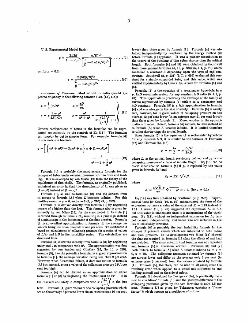
TABLE 1 VALUES OF COLLAPSING PRESSURES GIVEN BY VARIOUS INSTABILITY FORMULAS
(B - 30,000,000 lb per sq in., z - 0.3)Collapaiq pressure, in lb per aq in., b .LID 1001D [l [21 [1 inlbper sq in.,by formula [81 [91
/1[5] [6 [71 [8] [9
2 0.2 7.3 7.3 7.4 7.2 6.6 7.2 7.3 7.3 7.10.3 19.3 19.3 19.8 18.8 18.1 19.1 19.2 19.5 19.50.4 41.3 41.3 42.5 39.9 37.1 40.7 41.0 42.0 40.00.5 72.1 72.1 73.3 70.9 64.9 70.6 71.4 71.9 10.10.6 110.0 110.1 113.1 106.9 102.3 107.8 109.1 110.8 110.70.7 160.8 160.9 166.4 154.7 150.5 167.6 159.6 163.2 163.10.2 14.6 14.6 14.7 13.9 13.1 14.3 14.3 14.5 14.30.3 40.1 40.2 40.6 38.0 3L2 39.1 39.3 39:5 39.40.4 84.5 84.8 85.5 80.2 74.2 81.7 82.3 82.4 81.20.5 145.3 145.7 147.8 136.5 129.8 140.3 141.7 142.4 142.50.6 232.4 233.2 237.2 214.5 204.8 224.5 226.8 228.6 225.60.7 . 351.1 352.4 359.4 320.3 301.0 339.2 342.8 346.1 332.2
0.5 0.2 30.4 30.5 30.7 27.8 26.3 29.2 29.3 29.4 29.10.3 85.6 86.4 86.9 76.5 72.4 81.3 81.8 81.7 80.90.4 177.2 179.3 180.5 157.1 148.5 166.9 167.9 168.1 167.20.5 316.1 321.5 323.6 275.5 259.6 293.1 295.6 295.1 294.60.6 501.6 510.7 515.2 435.2 409.4 464.8 469.2 468.8 468.00.7 753.2 768.0 775.8 633.7 601.8 698.3 705.2 703.4 691.8
0.25 0.2 66.4 68.1 68.3 55.9 52.6 60.7 60.9 60.8 60.80.3 190.3 199.1 199.6 153.2 144.8 170.4 171.1 170.9 170.70.4 404.8 431.0 432.5 314.4 297.0 355.8 357.6 357.1 355.8
0.125 0.2 160.9 182.4 182.6 111.4 105.1 132.8 133.1 132.9 133.10.3 485.0 581.5 582.5 307.2 289.6 881.4 382.5 381.8 382.7
0.020
L0015
V0.i0900.008.0.007
as+ 0005's0 0040
1 0.003
t) 0.0025I- o0020 I, N \ A 120
0.00110 015 0200 5 040 060 . 20 . 0 .0 1.O5.0Length + Diameter (L/D)
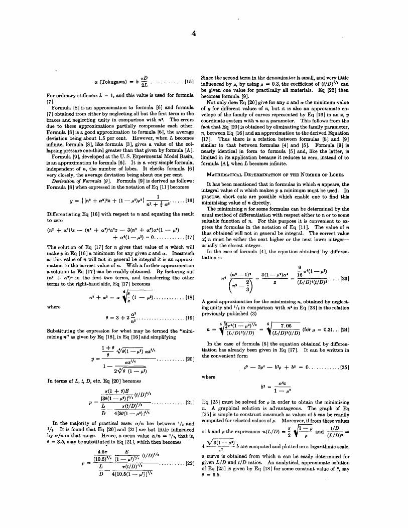
FIGo. 1 NUMBER OF LOBES n INTo WHICH A TUBE WILL COLLAPSEWHEIN SUBJECTD TO UNIFORM RADIAL AND AXIAL PRESSURE
(Based on formula [6] by von Mises.)
For formula [6], the one of most importance, a chart, Fig. 1,
has been prepared from which the correct integral value of nmay be determined at once for given LID and t/D ratios. Themethod used to construct the chart is similar to that employed
by von Mises (12, p. 754, Fig. 8). An arbitrary value of LIDand two arbitrary consecutive values of n (say 7 and 8) are
selected. These values are substituted in Eq [12] and two linearequations in z and y are obtained, one for n = 7 and one forn = 8. The two equations are solved simultaneously for z, thatis, for t1/D. This t1/D ratio in conjunction with the L/D ratiooriginally selected represent the dimensions of a vessel for which
either n = 7 or n'= 8 is determinative. Both values of a give
the same y and p. This procedure establishes one "division
point" on the chart. From many such points, the division linesof the chart are drawn.
The chart, Fig. 1, gives the best known theoretical value for n.It has been checked by experiment (see Table 3) as closely as thepractical determination of the number of lobes permits. Usuallythe same values of f are given by all the instability formulaspresented in this paper for a given L/D and t1/D. Fig. 1 is,therefore, not only correct for formula [6], but it is also a valua-ble aid in the use of the other formulas.
CALCULATIONS FOR THE COMPARISON OF FORMULAS
As a means of comparing-the various instability formulas, 23hypothetical pressure vessels with simple L/D and t/D ratios,ranging from L/D = 1/8 to 2 and t1/D = 0.002 to 0.007, wereselected. The dimensions of these vessels were so chosen as tobe completely representative of a series of models tested at theU. S. Experimental Model Basin, in order to facilitate the comn-
parison of 'formula predictions and experimental results. Thecollapsing pressures of the representative vessels were calculatedby each of the formulas, [1] to [9], inclusive, for E - 30,000,000lb per sq in. and ; = 0.3. The results are set forth in Table 1.
Percentage deviations of these calculated collapsing pressuresare listed in Table 2. The first five formulas are compared withformula [1], while the last four formulas and formula [1] arecompared with formula [6]. The comparison is confined to theinstability region only and to L/D ratios equal to or less than 2.The previous statements about percentage deviations are basedon the results shown in Table 2.
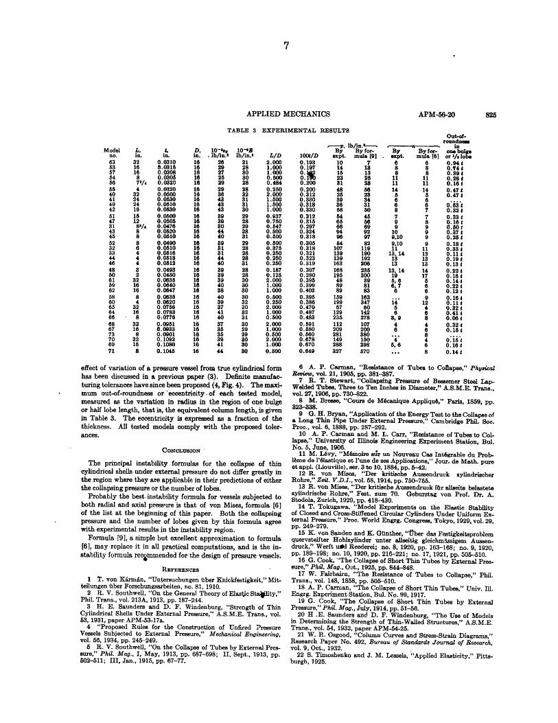
COMPARISON OF THEORETICAL AND EXPERIMENTAL RESULTS
The observed collapsing pressures of 36 models and their col-lapsing pressures as computed by formula [91] are given in Table3. This table is similar to and includes all the models listed in atable previously published (3) together with the results of testson 20 additional models. These later models include otherthicknesses. They are for the most part long models designed tocollapse in the region of instability. The models and their con-struction have been described in previous papers (3), (20).
Test results can be compared with the predictions of al formu-las by using formula [9] as the connecting link between Tables1 and 3, and selecting the proper representative vessel in Table 1.
A convenient graphical comparison of theoretical and experi-mental results follows.
GRAPHICAL REPRESENTATION OF EXPERIMENTAL RESULTS
Theoretical formulas give collapsing pressure as a function oftwo variables, the ratios LID and t/D. A p-LID coordinatesystem is commonly used to represent formulas graphically and
TABLE 2 PERCENTAGE DEVIATIONS OF COLLAPSINGPRESSUREI CALCULATED BY VARIOUS INSTABILITY
1 ORMULAS
--- From formula [I]-L/D lOOt/D [2] [3] [41 [5]2 0.2 0.0 0.9 - 2.4 -10.4
0.3 0.0 2.3 - 2.6 - 6.30.4 0.0 3.0 - 3.4 -10.00.5 0.0 1.7 - 1.6 -10.00.6 0.1 2.8 - 2.8 - 7.00.7 0.1 3.5 - 3.8 - 6.4
1 0.2 0.1 1.1 - 4.6 - 9.90.3 0.2 1.3 - 5.2 - 9.70.4 0.3 1.2 - 5.1 -12.20.5 0.3 1.7 - 6.1 -10.70.6 0.3 2.1 - 7.7 -11.90.7 0.4 2.3 - 8.8 -14.3
0.5 0.2 0.6 1.1 - 8.6 -13.50.3 0.8 1.4 -10.7 -15.50.4 1.2 1.9 -11.3 -16.2
0.25 0.2 2.6 2.8 -15.9 -20.8
-From formula l[1] [7] [81 [9]1.3 0.4 0.9 -2.61.3 0.6 2.3 2.21.3 0.7 3.0 -1.82.1 1.1 1.7 -0.72.0 1.2 2.8 2.72.0 1.3 3.5 8.51.9 0.3 1.0 -0.42.6 0.6 1.2 0.93.5 0.8 0.9 -0.63.5 1.0 1.5 1.63.5 1.0 1.8 0.53.5 1.0 2.0 -2.14.0 0.3 0.5 -0.45.3 0.6 0.5 -0.56.1 0.6 0.7 0.29.4 0.3 0.2 0.9
n byformula [61
11ll
CHART FOR .---015
NUMER OF L0.IS \ 0010
'
o.0o9
I- sI--7-. 10"0, I
_ \ INI~l IX, X \ -I- - - ,oots... "'-. IN INI ' ', m\I0I006... 'q \I I\I l., ..X'l\ J I I I10I 5,,\\X kX-,%,l ,I X lJ A I 10045o
I .__ _ __ . I__
to compare them with experimental results. For every value oft1/D a separate curve is required in such a system (4, Fig. 2) andit is difficult to plot and interpret experimental results.
It is desirable, therefore, to introduce coordinates 4o and Xo,defined as follows:
S2t/ .................. [26]2t/D/
4 (L/D)' /Xo I (lOOt/D) ................. [27]
for, it will be shown, in this coordinate system the points repre-senting all vessels in the instability region, with any t/D or L/Dratios, theoretically should fall on a single curve. With thesecoordinates formula [91, if the small (t/D)i term in the de-nominator is neglected, becomes
0.00121E 1o = (1 - ')
1/' ............. [28]
which is identical in form to Euler's equation. It may be notedfrom Eq [26] that e0 is what is commonly called the hoop stress.
Eq [28] shows that Vo is analogous 0to the slndernes ratio.lI/r, of column theo . This can be demonstrated in the follow-Ing manner:! bulge or half-lobe length of the circumferen-tial belt of a pressure vessel is analogous to a column whose
rD 1length is l = w- and whose radius of gyration is r = - t (5,
2n v N/1II, p. 506). It is seen that the analog of the slenderness ratio ofcolumn theory is
1 const.r n(t/D)................. [29]
Using the simple expression for a given by Eq [24] in Eq [291
r const. (tlD) ................ [30]
Comparison with Eq [271] shows that 1/r is equivalent to )o.Differences in the physical properties of the material of ex-
perimental models can be corrected for by converting 4o and Xoto the variables
#0o P.o4 = to ...... . .. [31]sV 2s(t/D)
1000 s8, (1- p"'' (L/ '1 - p '/'
X E 0.91 (t/D) 0.91 /.... [32]
or, for p = 0.3
1000 8 (LD)l 8, 3]X XiD) .......... [33]I E y ~(t/ D)* I B '""'
where as is the yield point of the material. # nky be called the"pressure factor" and X the "thinness factor." The relationship,Eq [28], remains unchanged by the transformation to the newvariables and it is now independent of the properties of the mate-rial. This transformation, except for the (1- 2)'/' factor, whichis nearly unity, is the same as the one adopted by Osgood (21)for columns. Formula tcmnnw.obe written
1.30 -. . . ............. [34 ]
where
= 0.045 1000 sy 1 - ') (lOOtD) ...... [35]1E \0.91 ) (100t/ D)-
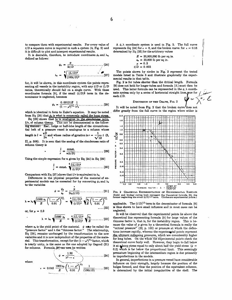
A #, X coordinate system is used in Fig. 2. The full curverepresents Eq [34] for e = 0, and the broken curve for e = 0.15determined by Eq [35] for the arbitrary values
E = 30,000,000 lb per sq in.sy - 30,000 lb per sq in.p = 0.3
t/D = 0.003
The points shown by circles in Fig. 2 represent the testedmodels listed in Table 3 and illustrate graphically the experi-mental results in that table.
Fig. 2 is for tubes shorter than the dritical length. Formula[9] does not hold for longer tubes and formula [A] must then beused. This latter formula can be represented in the #, X coordi-nate system only by a series of horizontal straight lines, ne foreach tID.
DIscussioN or THE GnarnAPH, FIG. 2 -X
It will be noted from Fig. 2 that the broken curve does notdiffer greatly from the full curve in the region where either is
I.E
1.2
0.5
0.4
0.3
0.2
0.12
0.07C 1 L - - #--
1.5 2.0 30 4.0 5.0
THINNESS FACTOR = A V(,tZW)E
FIG. 2 GRAPHICAL REPRESENTATION OF EXPERIMENTAL RESULTS
Solid and broken curves both represent the theoretical formula [9], theormer neglecting the small (t/D)2/0 term. Circles are experimental points.)
applicable. The (t/D)'1 t term in the denominator of formula [9]is thus shown to have small influence and in most cases can beneglected.
It will be observed that the experimental points lie above thetheoretical line representing formula [9] for large values of thethinness factor X, that is, for the instability region. This is be-cause the value of p given by a theoretical formula is really the"critical pressure" (22, p. 165) or pressure at which the deflec-tions increase rapidly, whereas the experimqtal points representtultimate collapsing pressures, which *are considerably higherfor long tubes. On the w-hole t'e experimental points check thetheoretical curve fairly well. However, they begin to fall belowit at %hoop stress equal to only about half the yield stress (# =0.5) which is far below the proportional limit. This seeminglypremature beginning of the intermediate region is due primarilyto imperfections in the models.
In general, imperfections in a pressure vessel have considerableinfluence on their strength, largely because the position of thebulges formed, and thus the position of the equivalent columns,is determined by the initial irregularities of the shell. The
1- - 11 11 11 1111116l
o.s 0.6 0.e 1.0
1 10 1111 11 ,1 1
APPLIED MECHANICS
TABLE 3 EXPERIMENTAL RESULTS
- p, lb/in . .-By By for-
expt. mula [9110 714 1315 1323 2681 2848 5625 2339 3436 3158 5054 4565 5666 6994 9296 9784 82
107 119139 190139 192163 206168 235195 30048 3989 8189 83
159 163199 34767 60
129 142235 278112 107209 200281 380149 150288 298327 570
Out-of-roundnme
'-------inBy By for- one bulge
Sexpt. mula [6] or I/s lobe6 6 0.948 8 0.Y4 18 8 0.39 t
11 11 0.26 t11 11 0.16 t14 14 0.47a 5 0.4786 66 6 0.538 7 0.32 47 7 0.33 t9 8 0.16 t9 9 0.50 t
10 9 0.37 t9,10 9 0.28 t9,10 9 0.18 t11 11 0.33 *
13, 14 13 0.11 t13 13 0.1913 13 0.13 t
13, 14 14 0.22 t19 17 0.165,6 6 0.14 86, 7 6 0.22 86 6 0.12 t
9 0.16 814 12 0.11 t5 4 0.32 t6 6 0.41 f
8,9 8 0.0684 4 0.32 86 6 0.15
... 84 4 0.15 t
5, 6 6 0.16 t.. 8 0.14 t
effect of variation of a pressure vessel from true cylindrical formhas been discussed in a previous paper (3). Definite manufac-turing tolerances have since been proposed (4, Fig. 4). The maxi-mum out-of-roundness or eccentricity -of each tested model,measured as the variation in radius in the region of one bulgeor half lobe length, that is, the equivalent column length, is givenin Table 3. The eccentricity is expressed as a fraction of thethickness. All tested models comply with the proposed toler-ances.
CONCLUsION
The principal instability formulas for the collapse of thincylindrical shells under external pressure do not differ greatly inthe region where they are applicable in their predictions of eitherthe collapsing pressure or the number of lobes.
Probably the best -instability formula for vessels subjected toboth radial and axial pressure is that of von Mises, formula [6]of the list at the beginning of this paper. Both the collapsingpressure and the number of lobes given by this formula agreewith experimental results in the instability region.
Formula [9], a simple but excellent approximation to formula[6], may replace it in all practical computations, and is the in-stability formula recgmmended for the design of pressure vessels.
REFERENCES
1 T. von KArmAn, "Untersuchungen iuber Knickfestigkeit," Mit-telungen iber Forschungsarbeiten, no. 81, 1910.
2 R. V. Southwell, "On the General Theory of Elastic Stality,"Phil. Trans., vol. 213A, 1913, pp. 187-244.
3 H. E. Saunders and D. F. Windenburg, "Strength of ThinCylindrical Shells Under External Pressure," A.S.M.E. Trans., vol.53, 1931, paper APM-53-17a.
4 "Proposed Rules for the Construction of Unfired PressureVessels Subjected to External Pressure," Mechanical Engineering,vol. 56, 1934, pp. 245-249.5 R. V. Southwell, "On the Collapse of Tubes by External Pres-
sure," Phil. Mag., I, May, 1913, pp. 687-698; II, Sept., 1913, pp.502-511; III, Jan., 1915, pp. 67-77.
6 A. P. Carman, "Resistance of Tubes to Collapse," PhysicalReview, vol. 21, 1905, pp. 381-387.7 R. T. Stewart, "Collapsing Pressure of Bessemer Steel Lap-Welded Tubes, Three to Ten Inches in Diameter," A.S.M.E. Trans.,vol. 27, 1906, pp. 730-822.
8 M. Bresse, "Cours de M6canique Appllqu6," Paris, 1859, pp.323-338.9 G.H. Bryan, "Application of the Energy Test to the Collapse ofa Long Thin Pipe Under External Pressure," Cambridge Phil. Soc.Proc., vol. 6, 1888, pp. 287-292.
10 A. P. Carman and M. L. Carr, "Resistance of Tubes to Col-lapse," University of Illinois Engineering Experiment Station, Bul.No. 5, June, 1906.
11 M. L6vy, "M6moire sir un Nouveau Cas Int6grable du Prob-1me de l'61astique et l'une de sea Applications," Jour. de Math. pureet appl. (Liouville), ser. 3 to 10, 1884, pp. 5-42.
12 R. von Mises, "Der kritische Aussendruck zylindrischerRohre," Zeit. V.D.I., vol. 58, 1914, pp. 750-755.
13 R. von Mises, "Der kritische Aussendruck fLr allseits belastetezylindrische Rohre," Fest. zum 70. Geburstag von Prof. Dr. A.Stodola, Zurich, 1929, pp. 418-430.
14 T. Tokugawa, "Model Experiments on the Elastic Stabilityof Closed and Cross-Stiffened Circular Cylinders Under Uniform Ex-ternal Pressure," Proc. World Engrg. Congress, Tokyo, 1929, vol. 29,pp. 249-279.
15 K. von Sanden and K. Ginther, "ber das Festigkeitsproblemquervsteifter Hohlzylinder unter allseitig gleichmniasigem Aussen-druck," Werft uiEd Reederei; no. 8, 1920, pp. 163-168; no. 9, 1920,pp. 189-198; no. 10, 1920, pp. 216-221; no. 17, 1921, pp. 505-510.
16 G. Cook, "The Collapse of Short Thin Tubes by External Pres-sure," Phil. Mag., Oct., 1925, pp. 844-848.
17 W. Fairbairn, "The Resistance of Tubes to Collapse," Phil.Trans., vol. 148, 1858, pp. 505-510.
18 A. P. Carman, "The Collapse of Short Thin Tubes," Univ. Ill.Engrg. Experiment Station, Bul. No. 99, 1917.
19 G. Cook, "The Collapse of Short Thin Tubes by ExternalPressure," Phil. Mag., July, 1914, pp. 51-56.
20 H .E. Saunders and D. F. Windenburg, "The Use of Modelsin Determining the Strength of Thin-Walled Structures," A.S.M.E.Trans., vol. 54, 1932, paper APM-54-25.
21 W. R. Osgood, "Column Curves and Stress-Strain Diagrams,"Research Paper No. 492, Bureau of Standards Journal of Research,vol. 9, Oct., 1932.
22 S. Timoshenko and J. M. Lessels, "Applied Elasticity," Pitts-burgh, 1925.
APM-56-20
Modelno.635357545655404149425147314345523233444648506159625860656466686773706971
L,
in.321616878/44
3224241615128'/4888644432
32161684
32168
32168
32168
.1,in.
0.03100.03150.03080.03050.03200.03200.05000.05300.05100.05300.05000.05050.04760.05200.05100.04900.05100.05160.05180.05120.04930.04500.06350.06400.06470.06350.06200.07560.07830: 07760.09510.09330.09010.10920.10800.1045
10-s8YSlb/in.2
262927252929364343433939804440898181444039393940384039374140373535394144
10-IRlb/in.'
3128303028283231313029282928312928282831282830303030323032313029290so
3030
L/D2.0001.0001.0000.8000.4840.2502.0001.5001.5001.0000.9370.7500.5470.5000.5000.5000.3750.2500.2500.2500.1870.1252.0001.0001.0000.5000.2502.0001.0000.5002.0001.0000.5002.0001.0000.500
1001/D0.1930.1970.J0.11is0.2000.2000.3120.3300.3180.3300.3120.3150.2970.3240.3180.3050.3180.3210.3230.3190.3070.2800.3950.3990.4030.3950.3860.4700.4870.4830.5910.5800.5600.6780.6700.649
1 uil I hII INMIMum .


a n m r rn h ii IdIhIIN i ,~,I, I NiMI191
-'V - ~- -
3 9080 02753 9748
A'--,- "-
$SX'tt S2 m
I - 1. - ,

'K
A4 "'17
-. A
~' 22p *7 ~
rj ~
-, 1,
$1.'Ifb.
I
-Sw
,1A"
'I
4-1 $-t%4 4n;t'l Yr I'
4 ~ ~~ . , n 'A(
Aix.
~--._
'-I'-.
-F
.11
r~. 1'
* ;'
'~I~' -. rt
k Q
>4**1
rw
, 'i'1
,LT 3'K V r 'MUi
7i4
0 1 1j~I]
'Pg If,- g - -a

![D } ( v ] t & o } Á ] v P Z ] À ] v Z } Á v o } Á X...DEVGAD BASIN DIST SINDHUDURG GAD BASIN KARLI BASIN TAREKHOL GURLA BASI BASIN TILL ARABIAN SEA BASIN BASIN](https://img.pdfslide.us/doc/110x75/611cc0a9b5ab866dc74adcf1/d-v-t-o-v-p-z-v-z-v-o-x-devgad-basin-dist.jpg)