Embed Size (px)
Citation preview
Unitronics 1
V200-18-E46B Snap-in I/O Module
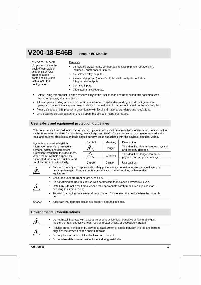
The V200-18-E46B plugs directly into the back of compatible Unitronics OPLCs, creating a self-contained PLC unit with a local I/O configuration.
Features
18 isolated digital inputs configurable to type pnp/npn (source/sink), includes 2 shaft encoder inputs.
15 isolated relay outputs.
2 isolated pnp/npn (source/sink) transistor outputs, includes 2 high-speed outputs.
9 analog inputs.
2 isolated analog outputs.
Before using this product, it is the responsibility of the user to read and understand this document and any accompanying documentation.
All examples and diagrams shown herein are intended to aid understanding, and do not guarantee operation. Unitronics accepts no responsibility for actual use of this product based on these examples.
Please dispose of this product in accordance with local and national standards and regulations.
Only qualified service personnel should open this device or carry out repairs.
User safety and equipment protection guidelines
This document is intended to aid trained and competent personnel in the installation of this equipment as defined by the European directives for machinery, low voltage, and EMC. Only a technician or engineer trained in the local and national electrical standards should perform tasks associated with the device‘s electrical wiring.
Symbols are used to highlight information relating to the user‘s personal safety and equipment protection throughout this document. When these symbols appear, the associated information must be read carefully and understood fully.
Symbol Meaning Description
Danger
The identified danger causes physical and property damage.
Warning
The identified danger can cause physical and property damage.
Caution Caution Use caution.
Failure to comply with appropriate safety guidelines can result in severe personal injury or property damage. Always exercise proper caution when working with electrical equipment.
Check the user program before running it.
Do not attempt to use this device with parameters that exceed permissible levels.
Install an external circuit breaker and take appropriate safety measures against short-circuiting in external wiring.
To avoid damaging the system, do not connect / disconnect the device when the power is on.
Caution Ascertain that terminal blocks are properly secured in place.
Environmental Considerations
Do not install in areas with: excessive or conductive dust, corrosive or flammable gas, moisture or rain, excessive heat, regular impact shocks or excessive vibration.
Provide proper ventilation by leaving at least 10mm of space between the top and bottom edges of the device and the enclosure walls.
Do not place in water or let water leak onto the unit.
Do not allow debris to fall inside the unit during installation.
V200-18-E46B Snap-in I/O Module 5/10
2 Unitronics
Wiring
Do not touch live wires.
Unused pins should not be connected. Ignoring this directive may damage the device.
Do not connect the ‗Neutral‘ or ‗Line‘ signal of the 110/220VAC to the device‘s 0V pin.
Double-check all wiring before turning on the power supply.
Wiring Procedures
Use crimp terminals for wiring; use 26-12 AWG wire (0.13mm 2–3.31mm
2) for all wiring purposes.
1. Strip the wire to a length of 7±0.5mm (0.250–0.300 inches).
2. Unscrew the terminal to its widest position before inserting a wire.
3. Insert the wire completely into the terminal to ensure that a proper connection can be made.
4. Tighten enough to keep the wire from pulling free.
To avoid damaging the wire, do not exceed a maximum torque of 0.5 N·m (5 kgf·cm).
Do not use tin, solder, or any other substance on stripped wire that might cause the wire strand to break.
Install at maximum distance from high-voltage cables and power equipment.
I/O Wiring—General
Input or output cables should not be run through the same multi-core cable or share the same wire.
Allow for voltage drop and noise interference with input lines used over an extended distance. Use wire that is properly sized for the load.
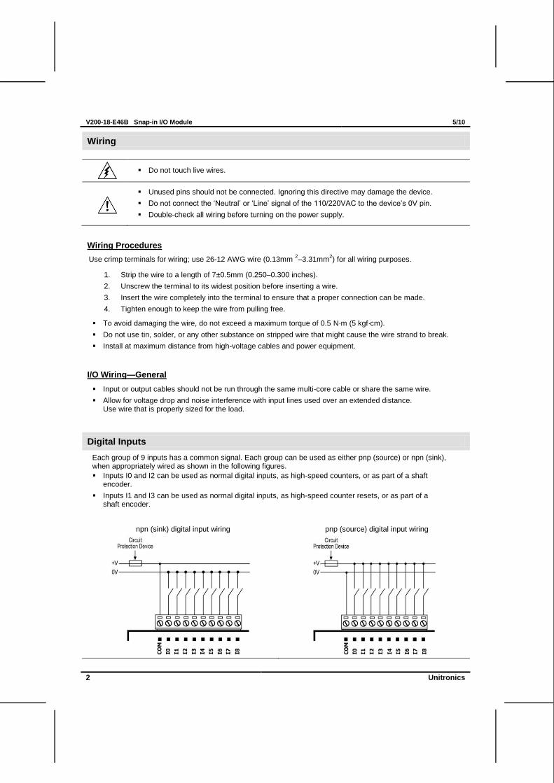
Digital Inputs
Each group of 9 inputs has a common signal. Each group can be used as either pnp (source) or npn (sink), when appropriately wired as shown in the following figures.
Inputs I0 and I2 can be used as normal digital inputs, as high-speed counters, or as part of a shaft encoder.
Inputs I1 and I3 can be used as normal digital inputs, as high-speed counter resets, or as part of a shaft encoder.
npn (sink) digital input wiring pnp (source) digital input wiring
5/10 V200-18-E46B Snap-in I/O Module
Unitronics 3
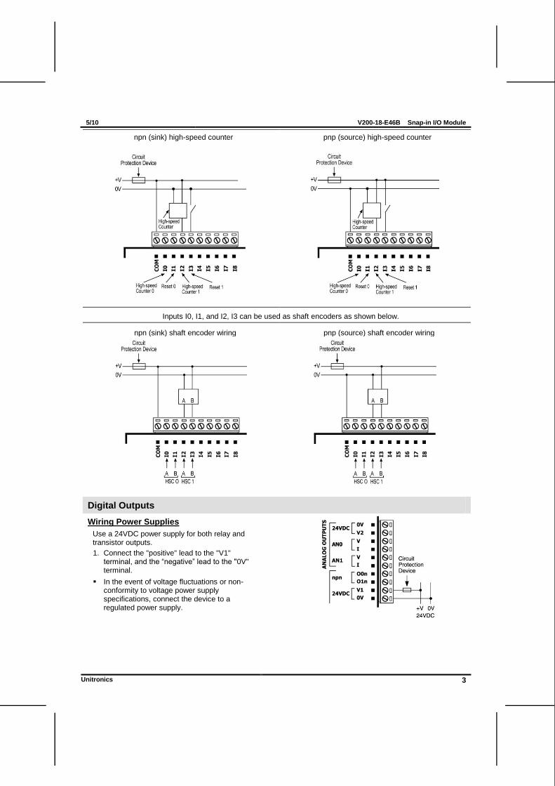
npn (sink) high-speed counter pnp (source) high-speed counter
Inputs I0, I1, and I2, I3 can be used as shaft encoders as shown below.
npn (sink) shaft encoder wiring pnp (source) shaft encoder wiring
Digital Outputs
Wiring Power Supplies
Use a 24VDC power supply for both relay and transistor outputs.
1. Connect the "positive" lead to the "V1" terminal, and the ―negative‖ lead to the "0V" terminal.
In the event of voltage fluctuations or non-conformity to voltage power supply specifications, connect the device to a regulated power supply.
V200-18-E46B Snap-in I/O Module 5/10
4 Unitronics
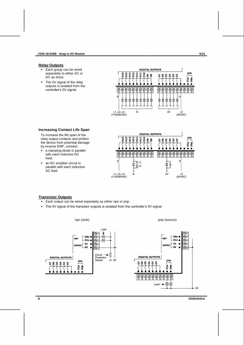
Relay Outputs
Each group can be wired separately to either AC or DC as show.
The 0V signal of the relay outputs is isolated from the controller‘s 0V signal.
Increasing Contact Life Span
To increase the life span of the relay output contacts and protect the device from potential damage by reverse EMF, connect:
a clamping diode in parallel with each inductive DC load,
an RC snubber circuit in parallel with each inductive AC load.
Transistor Outputs
Each output can be wired separately as either npn or pnp.
The 0V signal of the transistor outputs is isolated from the controller‘s 0V signal.
npn (sink) pnp (source)
5/10 V200-18-E46B Snap-in I/O Module
Unitronics 5
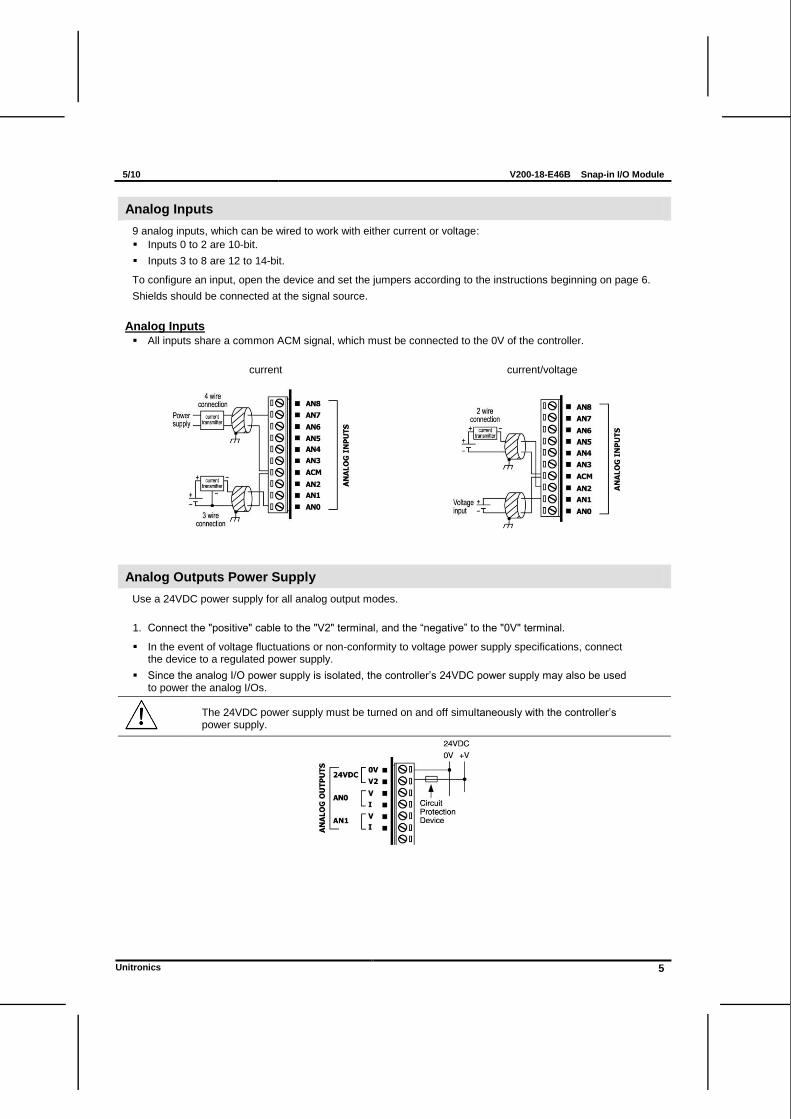
Analog Inputs
9 analog inputs, which can be wired to work with either current or voltage:
Inputs 0 to 2 are 10-bit.
Inputs 3 to 8 are 12 to 14-bit.
To configure an input, open the device and set the jumpers according to the instructions beginning on page 6.
Shields should be connected at the signal source.
Analog Inputs
All inputs share a common ACM signal, which must be connected to the 0V of the controller.
current current/voltage
Analog Outputs Power Supply
Use a 24VDC power supply for all analog output modes.
1. Connect the "positive" cable to the "V2" terminal, and the ―negative‖ to the "0V" terminal.
In the event of voltage fluctuations or non-conformity to voltage power supply specifications, connect the device to a regulated power supply.
Since the analog I/O power supply is isolated, the controller‘s 24VDC power supply may also be used to power the analog I/Os.
The 24VDC power supply must be turned on and off simultaneously with the controller‘s power supply.
V200-18-E46B Snap-in I/O Module 5/10
6 Unitronics
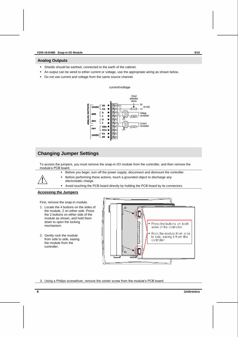
Analog Outputs
Shields should be earthed, connected to the earth of the cabinet.
An output can be wired to either current or voltage, use the appropriate wiring as shown below.
Do not use current and voltage from the same source channel.
current/voltage
Changing Jumper Settings
To access the jumpers, you must remove the snap-in I/O module from the controller, and then remove the module‘s PCB board.
Before you begin, turn off the power supply, disconnect and dismount the controller.
Before performing these actions, touch a grounded object to discharge any electrostatic charge.
Avoid touching the PCB board directly by holding the PCB board by its connectors.
Accessing the Jumpers
First, remove the snap-in module.
1. Locate the 4 buttons on the sides of the module, 2 on either side. Press the 2 buttons on either side of the module as shown, and hold them down to open the locking mechanism.
2. Gently rock the module from side to side, easing the module from the controller.
3. Using a Philips screwdriver, remove the center screw from the module‘s PCB board.
5/10 V200-18-E46B Snap-in I/O Module
Unitronics 7
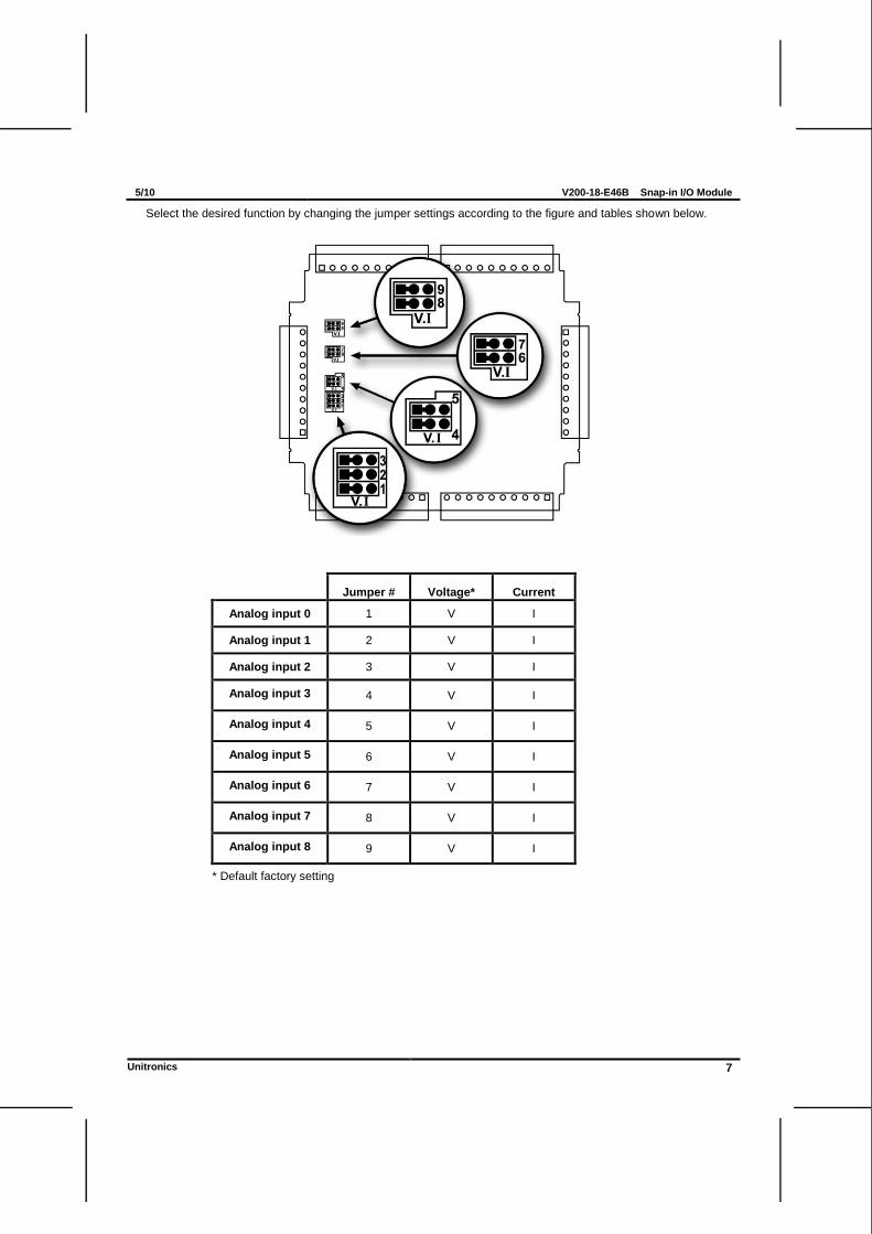
Select the desired function by changing the jumper settings according to the figure and tables shown below.
Jumper # Voltage* Current
Analog input 0 1 V I
Analog input 1 2 V I
Analog input 2 3 V I
Analog input 3 4 V I
Analog input 4 5 V I
Analog input 5 6 V I
Analog input 6 7 V I
Analog input 7 8 V I
Analog input 8 9 V I
* Default factory setting
V200-18-E46B Snap-in I/O Module 5/10
8 Unitronics
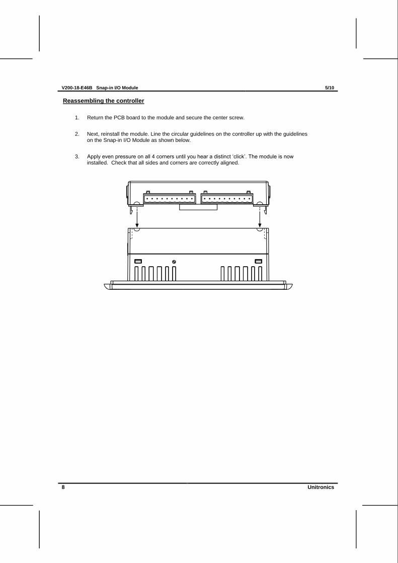
Reassembling the controller
1. Return the PCB board to the module and secure the center screw.
2. Next, reinstall the module. Line the circular guidelines on the controller up with the guidelines on the Snap-in I/O Module as shown below.
3. Apply even pressure on all 4 corners until you hear a distinct ‗click‘. The module is now installed. Check that all sides and corners are correctly aligned.
5/10 V200-18-E46B Snap-in I/O Module
Unitronics 9
V200-18-E46B Technical Specifications
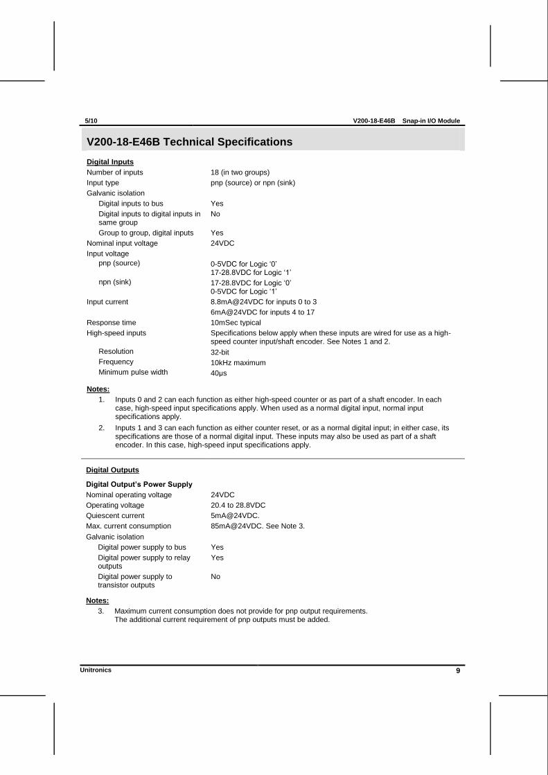
Digital Inputs
Number of inputs 18 (in two groups)
Input type pnp (source) or npn (sink)
Galvanic isolation
Digital inputs to bus Yes
Digital inputs to digital inputs in same group
No
Group to group, digital inputs Yes
Nominal input voltage 24VDC
Input voltage
pnp (source) 0-5VDC for Logic ‗0‘ 17-28.8VDC for Logic ‗1‘
npn (sink) 17-28.8VDC for Logic ‗0‘ 0-5VDC for Logic ‗1‘
Input current 8.8mA@24VDC for inputs 0 to 3
6mA@24VDC for inputs 4 to 17
Response time 10mSec typical
High-speed inputs Specifications below apply when these inputs are wired for use as a high-speed counter input/shaft encoder. See Notes 1 and 2.
Resolution 32-bit
Frequency 10kHz maximum
Minimum pulse width 40μs
Notes:
1. Inputs 0 and 2 can each function as either high-speed counter or as part of a shaft encoder. In each case, high-speed input specifications apply. When used as a normal digital input, normal input specifications apply.
2. Inputs 1 and 3 can each function as either counter reset, or as a normal digital input; in either case, its specifications are those of a normal digital input. These inputs may also be used as part of a shaft encoder. In this case, high-speed input specifications apply.
Digital Outputs
Digital Output’s Power Supply
Nominal operating voltage 24VDC
Operating voltage 20.4 to 28.8VDC
Quiescent current 5mA@24VDC.
Max. current consumption 85mA@24VDC. See Note 3.
Galvanic isolation
Digital power supply to bus Yes
Digital power supply to relay outputs
Yes
Digital power supply to transistor outputs
No
Notes:
3. Maximum current consumption does not provide for pnp output requirements. The additional current requirement of pnp outputs must be added.
V200-18-E46B Snap-in I/O Module 5/10
10 Unitronics
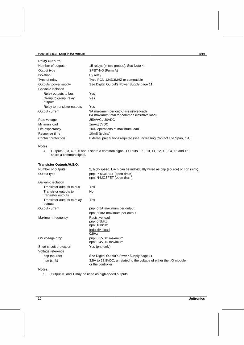
Relay Outputs
Number of outputs 15 relays (in two groups). See Note 4.
Output type SPST-NO (Form A)
Isolation By relay
Type of relay Tyco PCN-124D3MHZ or compatible
Outputs‘ power supply See Digital Output‘s Power Supply page 11.
Galvanic isolation
Relay outputs to bus Yes
Group to group, relay outputs
Yes
Relay to transistor outputs Yes
Output current 3A maximum per output (resistive load) 8A maximum total for common (resistive load)
Rate voltage 250VAC / 30VDC
Minimun load 1mA@5VDC
Life expectancy 100k operations at maximum load
Response time 10mS (typical)
Contact protection External precautions required (see Increasing Contact Life Span, p.4)
Notes:
4. Outputs 2, 3, 4, 5, 6 and 7 share a common signal. Outputs 8, 9, 10, 11, 12, 13, 14, 15 and 16 share a common signal.
Transistor Outputs/H.S.O.
Number of outputs 2, high-speed. Each can be individually wired as pnp (source) or npn (sink).
Output type pnp: P-MOSFET (open drain) npn: N-MOSFET (open drain)
Galvanic isolation
Transistor outputs to bus Yes
Transistor outputs to transistor outputs
No
Transistor outputs to relay outputs
Yes
Output current pnp: 0.5A maximum per output
npn: 50mA maximum per output
Maximum frequency Resistive load pnp: 0.5kHz npn: 100kHz
Inductive load 0.5Hz
ON voltage drop pnp: 0.5VDC maximum npn: 0.4VDC maximum
Short circuit protection Yes (pnp only)
Voltage reference
pnp (source) See Digital Output‘s Power Supply page 11
npn (sink) 3.5V to 28.8VDC, unrelated to the voltage of either the I/O module or the controller
Notes:
5. Output #0 and 1 may be used as high-speed outputs.
5/10 V200-18-E46B Snap-in I/O Module
Unitronics 11
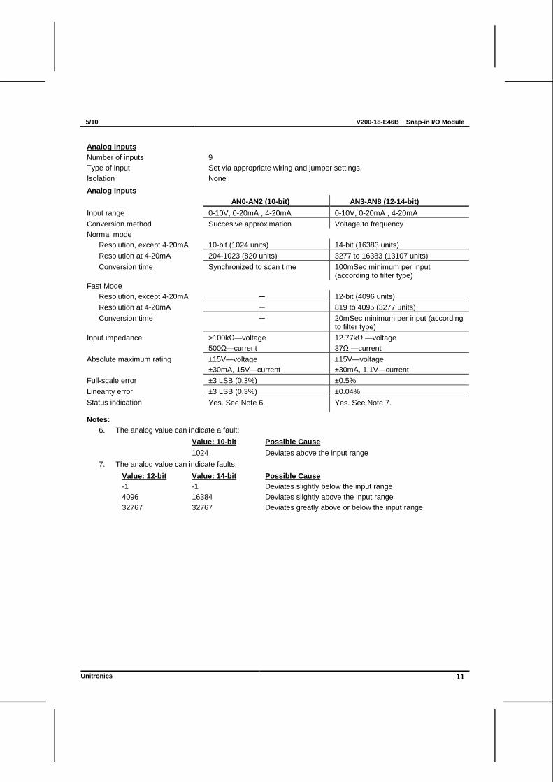
Analog Inputs
Number of inputs 9
Type of input Set via appropriate wiring and jumper settings.
Isolation None
Analog Inputs
AN0-AN2 (10-bit) AN3-AN8 (12-14-bit)
Input range 0-10V, 0-20mA , 4-20mA 0-10V, 0-20mA , 4-20mA
Conversion method Succesive approximation Voltage to frequency
Normal mode
Resolution, except 4-20mA 10-bit (1024 units) 14-bit (16383 units)
Resolution at 4-20mA 204-1023 (820 units) 3277 to 16383 (13107 units)
Conversion time Synchronized to scan time 100mSec minimum per input (according to filter type)
Fast Mode
Resolution, except 4-20mA ─ 12-bit (4096 units)
Resolution at 4-20mA ─ 819 to 4095 (3277 units)
Conversion time ─ 20mSec minimum per input (according to filter type)
Input impedance >100kΩ—voltage
500Ω—current
12.77kΩ —voltage
37Ω —current
Absolute maximum rating ±15V—voltage
±30mA, 15V—current
±15V—voltage
±30mA, 1.1V—current
Full-scale error ±3 LSB (0.3%) ±0.5%
Linearity error ±3 LSB (0.3%) ±0.04%
Status indication Yes. See Note 6. Yes. See Note 7.
Notes:
6. The analog value can indicate a fault:
Value: 10-bit Possible Cause
1024 Deviates above the input range
7. The analog value can indicate faults:
Value: 12-bit Value: 14-bit Possible Cause
-1 -1 Deviates slightly below the input range
4096 16384 Deviates slightly above the input range
32767 32767 Deviates greatly above or below the input range
V200-18-E46B Snap-in I/O Module 5/10
12 Unitronics
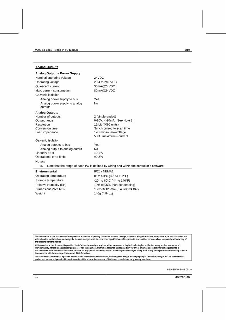
Analog Outputs
Analog Output’s Power Supply
Nominal operating voltage 24VDC
Operating voltage 20.4 to 28.8VDC
Quiescent current 30mA@24VDC
Max. current consumption 80mA@24VDC
Galvanic isolation
Analog power supply to bus Yes
Analog power supply to analog outputs
No
Analog Outputs
Number of outputs 2 (single-ended)
Output range 0-10V, 4-20mA. See Note 8.
Resolution 12-bit (4096 units)
Conversion time Synchronized to scan time
Load impedance 1kΩ minimum—voltage
500Ω maximum—current
Galvanic isolation
Analog outputs to bus Yes
Analog output to analog output No
Linearity error ±0.1%
Operational error limits ±0.2%
Notes:
8. Note that the range of each I/O is defined by wiring and within the controller‘s software.
Environmental IP20 / NEMA1
Operating temperature 0 to 50C (32 to 122F)
Storage temperature -20 to 60C (-4 to 140F)
Relative Humidity (RH) 10% to 95% (non-condensing)
Dimensions (WxHxD) 138x23x123mm (5.43x0.9x4.84‖)
Weight 140g (4.94oz)
The information in this document reflects products at the date of printing. Unitronics reserves the right, subject to all applicable laws, at any time, at its sole discretion, and without notice, to discontinue or change the features, designs, materials and other specifications of its products, and to either permanently or temporarily withdraw any of the forgoing from the market.
All information in this document is provided "as is" without warranty of any kind, either expressed or implied, including but not limited to any implied warranties of merchantability, fitness for a particular purpose, or non-infringement. Unitronics assumes no responsibility for errors or omissions in the information presented in this document. In no event shall Unitronics be liable for any special, incidental, indirect or consequential damages of any kind, or any damages whatsoever arising out of or in connection with the use or performance of this information.
The tradenames, trademarks, logos and service marks presented in this document, including their design, are the property of Unitronics (1989) (R"G) Ltd. or other third parties and you are not permitted to use them without the prior written consent of Unitronics or such third party as may own them
DSP-SNAP-E46B 05-10