Embed Size (px)
Citation preview
Owner’s Manual
�M�o�d�e�l�: �S�Q�A�-�2�1�3�0
�S�Q�A�-�4�0�7�5
�S�Q�A�-�1�0�0�0
�S�Q�A�-�4�1�0�0
V1 1004
CDT Audiophile Fanatics In California USA
CDT Audio,Inc.92 Second Street
Buellton, CaliforniaUSA
Ph:1-877-568-3238Fx:1-805-693-1898
Email:[email protected]
WWW.cdtaudio.com
WWW.cdtgold.com
ByDesign & Engineering
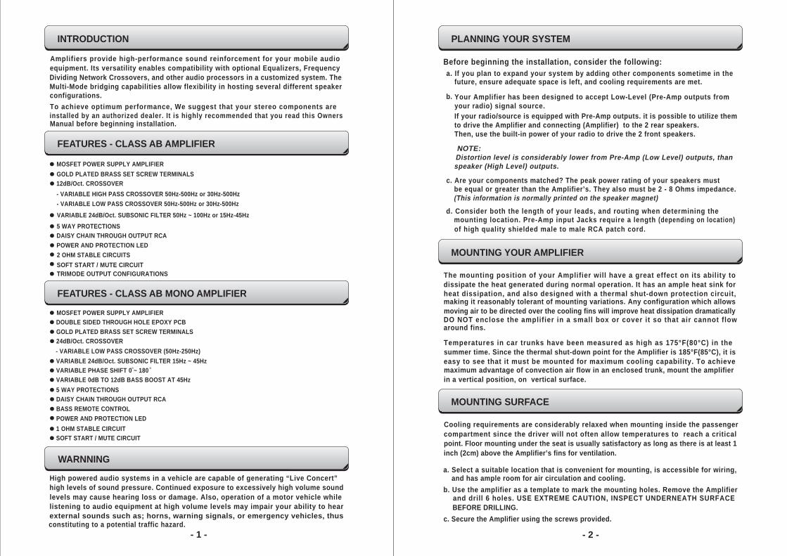
Amplifiers provide high-performance sound reinforcement for your mobile audioequipment. Its versatility enables compatibility with optional Equalizers, FrequencyDividing Network Crossovers, and other audio processors in a customized system. TheMulti-Mode bridging capabilities allow flexibility in hosting several different speakerconfigurations.To achieve optimum performance, We suggest that your stereo components areinstalled by an authorized dealer. It is highly recommended that you read this OwnersManual before beginning installation.
MOSFET POWER SUPPLY AMPLIFIERGOLD PLATED BRASS SET SCREW TERMINALS12dB/Oct. CROSSOVER- VARIABLE HIGH PASS CROSSOVER 50Hz-500Hz or 30Hz-500Hz- VARIABLE LOW PASS CROSSOVER 50Hz-500Hz or 30Hz-500Hz VARIABLE 24dB/Oct. SUBSONIC FILTER 50Hz ~ 100Hz or 15Hz-45Hz5 WAY PROTECTIONSDAISY CHAIN THROUGH OUTPUT RCAPOWER AND PROTECTION LED
SOFT START / MUTE CIRCUITTRIMODE OUTPUT CONFIGURATIONS
2 OHM STABLE CIRCUITS
- 1 -
INTRODUCTION
FEATURES - CLASS AB AMPLIFIER
FEATURES - CLASS AB MONO AMPLIFIER
- 2 -
WARNNING
PLANNING YOUR SYSTEM
High powered audio systems in a vehicle are capable of generating “Live Concert”high levels of sound pressure. Continued exposure to excessively high volume soundlevels may cause hearing loss or damage. Also, operation of a motor vehicle whilelistening to audio equipment at high volume levels may impair your ability to hearexternal sounds such as; horns, warning signals, or emergency vehicles, thusconstituting to a potential traffic hazard.
Before beginning the installation, consider the following:a. If you plan to expand your system by adding other components sometime in the
future, ensure adequate space is left, and cooling requirements are met.
b. Your Amplifier has been designed to accept Low-Level (Pre-Amp outputs from your radio) signal source. If your radio/source is equipped with Pre-Amp outputs. it is possible to utilize themto drive the Amplifier and connecting (Amplifier) to the 2 rear speakers.Then, use the built-in power of your radio to drive the 2 front speakers.
Distortion level is considerably lower from Pre-Amp (Low Level) outputs, than speaker (High Level) outputs.
c. Are your components matched? The peak power rating of your speakers must be equal or greater than the Amplifier’s. They also must be 2 - 8 Ohms impedance.(This information is normally printed on the speaker magnet)
d. Consider both the length of your leads, and routing when determining the mounting location. Pre-Amp input Jacks require a length (depending on location)of high quality shielded male to male RCA patch cord.
NOTE:
MOUNTING YOUR AMPLIFIER
The mounting position of your Amplifier will have a great effect on its ability to dissipate the heat generated during normal operation. It has an ample heat sink forheat dissipation, and also designed with a thermal shut-down protection circuit,making it reasonably tolerant of mounting variations. Any configuration which allowsmoving air to be directed over the cooling fins will improve heat dissipation dramaticallyDO NOT enclose the amplifier in a small box or cover it so that air cannot flow
around fins.
Temperatures in car trunks have been measured as high as 175°F(80°C) in thesummer time. Since the thermal shut-down point for the Amplifier is 185°F(85°C), it iseasy to see that it must be mounted for maximum cooling capability. To achievemaximum advantage of convection air flow in an enclosed trunk, mount the amplifierin a vertical position, on vertical surface.
MOUNTING SURFACE
Cooling requirements are considerably relaxed when mounting inside the passengercompartment since the driver will not often allow temperatures to reach a criticalpoint. Floor mounting under the seat is usually satisfactory as long as there is at least 1inch (2cm) above the Amplifier’s fins for ventilation.
a. Select a suitable location that is convenient for mounting, is accessible for wiring, and has ample room for air circulation and cooling.
b. Use the amplifier as a template to mark the mounting holes. Remove the Amplifier and drill 6 holes. USE EXTREME CAUTION, INSPECT UNDERNEATH SURFACEBEFORE DRILLING.
c. Secure the Amplifier using the screws provided.
VARIABLE 0dB TO 12dB BASS BOOST AT 45Hz
MOSFET POWER SUPPLY AMPLIFIERDOUBLE SIDED THROUGH HOLE EPOXY PCBGOLD PLATED BRASS SET SCREW TERMINALS24dB/Oct. CROSSOVER- VARIABLE LOW PASS CROSSOVER (50Hz-250Hz)
VARIABLE PHASE SHIFT 0 ~ 180VARIABLE 24dB/Oct. SUBSONIC FILTER 15Hz ~ 45Hz
5 WAY PROTECTIONSDAISY CHAIN THROUGH OUTPUT RCABASS REMOTE CONTROL
1 OHM STABLE CIRCUITSOFT START / MUTE CIRCUIT
POWER AND PROTECTION LED
- 3 - - 4 -
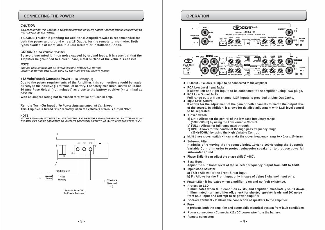
CONNECTING THE POWER
CAUTIONAS A PRECAUTION, IT IS ADVISABLE TO DISCONNECT THE VEHICLE’S BATTERY BEFORE MAKING CONNECTION TO THE + 12 VOLT SUPPLY WIRING.
4 GAUGE(Thicker if planning for additional Amplifiers)wire is recommended for both the power and ground wires. 18 Gauge, for the remote turn-on wire. Both types available at most Mobile Audio Dealers or Installation Shops.
GROUND : To Vehicle ChassisTo avoid unwanted ignition noise caused by ground loops, it is essential that the Amplifier be grounded to a clean, bare, metal surface of the vehicle’s chassis.NOTEGROUND WIRE SHOULD NOT BE EXTENDED MORE THAN 3 FT. (1 METER).USING THIS METFOD CAN CAUSE TURN ON AND TURN OFF TRANSIENTS (NOISE)
+12 Volt(Fused) Constant Power : To Battery (+)Due to the power requirements of the Amplifier, this connection should be made directly to the positive (+) terminal of battery. For safety measures, install an in-line 50 Amp Fuse Holder (not included) as close to the battery positive (+) terminal as possible .With an ampere rating not to exceed total value of fuses in amp.
Remote Turn-On Input :: To Power Antenna output of Car Stereo This Amplifier is turned “ON” remotely when the vehicle’s stereo is turned “ON”.
NOTEIF YOUR RADIO DOES NOT HAVE A +12 VOLT OUTPUT LEAD WHEN THE RADIO IS TURNED ON, “RMT” TERMINAL ONTHE AMPLIFIER CAN BE CONNECTED TO VEHICLE’S ACCESSORY CIRCUIT THAT IS LIVE WHEN THE KEY IS “ON”.
ChassisGround
(-)
FUSE Holder
NearBattery
Remote Turn ONTo Power Antenna
Battery
OPERATION
RCA Low Level Input Jackslt allows left and right inputs to be connected to the amplifier using RCA plugs.
RCA Line Output JacksFull range output from channel L&R inputs is provided at Line Out Jacks.
Input Level ControlIt allows for the adjustment of the gain of both channels to match the output levelof the source. In addition, it allows for detailed adjustment with L&R level controlto be separated.
X-over switcha) LPF : Allows for the control of the low pass frequency range
(30Hz-500Hz) by using the Low Variable Control.b) FULL : Allows for full range pass through.c) HPF : Allows for the control of the high pass frequency range
(30Hz-500Hz) by using the High Variable Control.
Subsonic FilterIt admits of removing the frequency below 10Hz to 100Hz using the SubsonicVariable Control in order to protect subwoofer speaker or to produce powerfulsubwoofer sound.
Power LED - lt indicates when amplifier is on and no fault existence. Protection LED
lt illuminates when fault condition exists, and amplifier immediately shuts down. lf illuminated, turn amplifier off, check for shorted speaker leads and DC noise from RCA input and attempt to re-power amplifier.
Speaker Terminal - It allows the connection of speakers to the amplifier.
Power connection - Connects +12VDC power wire from the battery.
FuseIt protects both the amplifier and automobile electrical system from fault conditions.
Multi times x-over switch - It can make the x-over freguency range to x 1 or x 10 times
Phase Shift - It can adjust the phase shift 0˚ ~180˚.
Hi-Input - It allows Hi-Input to be connected to the amplifier
Adjust the sub boost level of the selected frequency output from 0dB to 18dB. Bass Boost
a) F&R : Allows for the Front & rear input.b) F : Allows for the Front input only in case of using 2 channel input only.
Input Mode Selector
Remote connecton
OPERATION
- 5 -
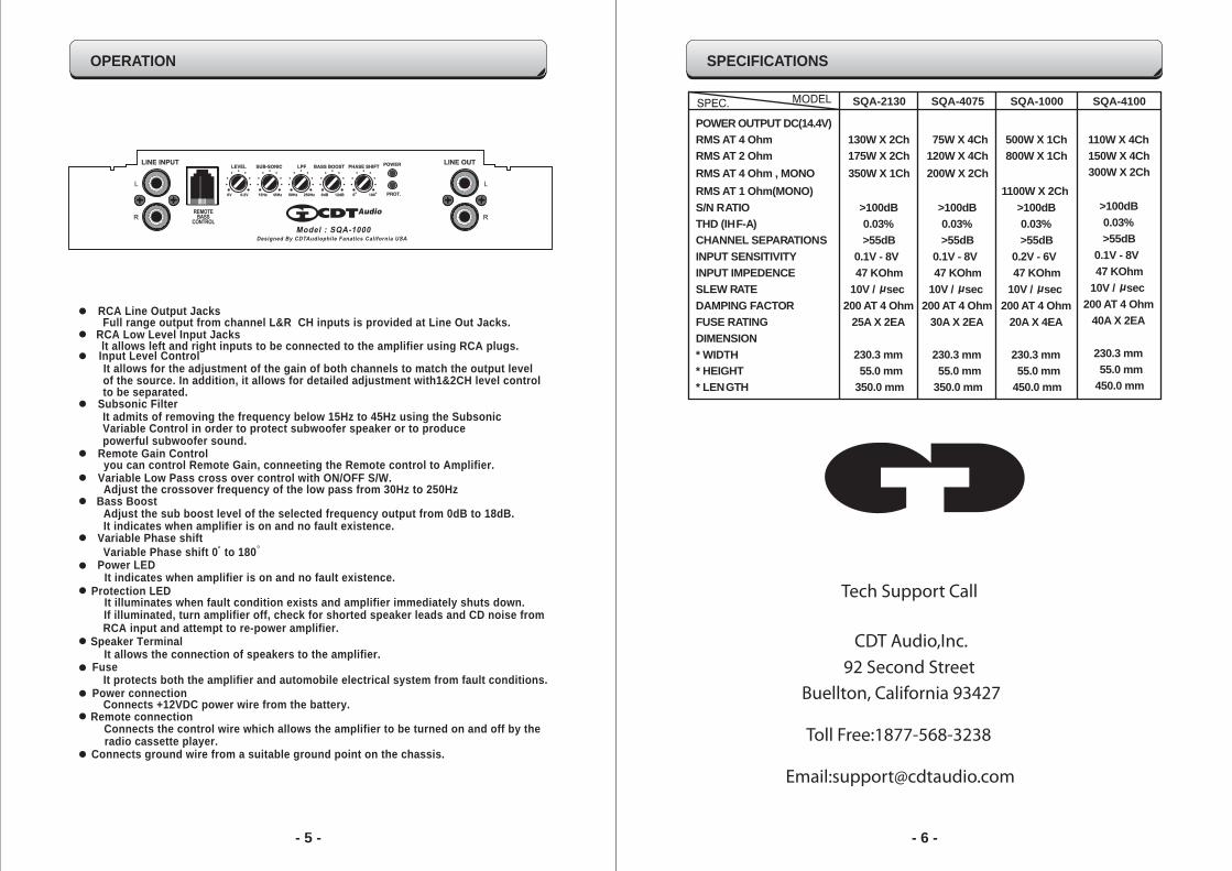
SPECIFICATIONS
- 6 -
POWER OUTPUT DC(14.4V)RMS AT 4 Ohm 130W X 2ChRMS AT 2 Ohm 175W X 2Ch
RMS AT 1 Ohm(MONO)S/N RATIO >100dBTHD (IHF-A) 0.03%CHANNEL SEPARATIONS >55dBINPUT SENSITIVITY 0.1V - 8VINPUT IMPEDENCE 47 KOhmSLEW RATE 10V / secDAMPING FACTOR 200 AT 4 OhmFUSE RATING 25A X 2EA
* WIDTH 230.3 mm* HEIGHT 55.0 mm* LENGTH 350.0 mm
DIMENSION
MODELSPEC. SQA-2130
µ
75W X 4Ch120W X 4Ch
>100dB0.03%>55dB
0.1V - 8V47 KOhm
10V / sec200 AT 4 Ohm
30A X 2EA
230.3 mm55.0 mm
350.0 mm
SQA-4075
µ
500W X 1Ch800W X 1Ch
1100W X 2ChRMS AT 4 Ohm , MONO 350W X 1Ch 200W X 2Ch
>100dB0.03%>55dB
0.2V - 6V47 KOhm
10V / sec200 AT 4 Ohm
20A X 4EA
230.3 mm55.0 mm
450.0 mm
SQA-1000
µ
CDT Audio,Inc.
Tech Support Call
92 Second StreetBuellton, California 93427
Toll Free:1877-568-3238
Email:[email protected]
RCA Low Level Input Jacks
RCA Line Output Jacks
It allows for the adjustment of the gain of both channels to match the output level Input Level Control
It admits of removing the frequency below 15Hz to 45Hz using the SubsonicVariable Control in order to protect subwoofer speaker or to producepowerful subwoofer sound.
Adjust the sub boost level of the selected frequency output from 0dB to 18dB.It indicates when amplifier is on and no fault existence.
of the source. In addition, it allows for detailed adjustment with1&2CH level controlto be separated.
Bass Boost
you can control Remote Gain, conneeting the Remote control to Amplifier.Remote Gain Control
Adjust the crossover frequency of the low pass from 30Hz to 250HzVariable Low Pass cross over control with ON/OFF S/W.
Variable Phase shift
Power LED
Protection LED
Variable Phase shift 0 to 180
It illuminates when fault condition exists and amplifier immediately shuts down.
It indicates when amplifier is on and no fault existence.
If illuminated, turn amplifier off, check for shorted speaker leads and CD noise fromRCA input and attempt to re-power amplifier.
Subsonic Filter
Speaker TerminalIt allows the connection of speakers to the amplifier.
Power connectionConnects +12VDC power wire from the battery.
FuseIt protects both the amplifier and automobile electrical system from fault conditions.
Remote connectionConnects the control wire which allows the amplifier to be turned on and off by theradio cassette player.
Connects ground wire from a suitable ground point on the chassis.
lt allows left and right inputs to be connected to the amplifier using RCA plugs.
Full range output from channel L&R CH inputs is provided at Line Out Jacks.
110W X 4Ch150W X 4Ch300W X 2Ch
>100dB0.03%>55dB
0.1V - 8V47 KOhm
10V / sec200 AT 4 Ohm
40A X 2EA
230.3 mm55.0 mm
450.0 mm
SQA-4100
µ