Embed Size (px)
Citation preview

Eltek — 2925 E Plano Pkwy, Plano, TX 75074, USA Phone: 469-330-9100 Eltek © 2018 – www.eltek.com
V Series Rectifier High Efficiency Module Doc 370096.DS3 Issue 1
KEY FEATURES • 96% EFFICIENCY • ONLY 2RU IN HEIGHT • OPERATES AT FULL POWER IN
TEMPERATURES UP TO +65ºC • CONSTANT CURRENT • NEBS LEVEL 3
V Series Rectifier High Efficiency Module Eltek V-series rectifiers provide industry-leading efficiency in a 2 RU footprint. Reliability, scalability, and hot-swap capability make for optimal system design and cost-effective deployment – from initial installation to future upgrades. The High-Efficiency ("HE") models deliver up to 96% conversion efficiency.
PRODUCT DESCRIPTION Vertically cooled 2RU rectifiers with wide range of output modules available.
THE ELTEK DIFFERENCE A BETTER CHOICE Energy efficiency is a practical choice that helps protect the environment. Eltek is committed to forming partnerships dedicated to this cause INDUSTRY-LEADING-EFFICIENCY With a peak efficiency over 96%, V-Series HE rectifiers reduce energy waste and costs. Since they generate less heat, it takes less energy to cool the equipment and immediate environment, thereby reducing expenses throughout the network. OPTIMIZATION Eltek rectifiers are optimized for the demanding power and power conversion needs of wireless communications, enter-prise and broad-band access equipment. FLEXIBILITY V-Series rectifiers are designed to operate in Eltek’s Compact and Integrated DC Power Systems.
Eltek — 2925 E Plano Pkwy, Plano, TX 75074, USA Phone: 469-330-9100 Eltek © 2018 – www.eltek.com
V Series Rectifier Doc 370096.DS3 – rev1 (2/6)
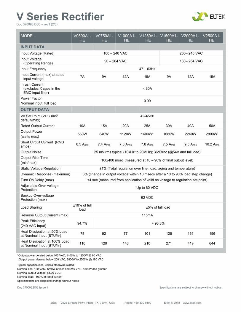
MODEL V0500A1-HE
V0750A1-HE
V1000A1-HE
V1250A1-HE
V1500A1-HE
V2000A1-HE
V2500A1-HE
INPUT DATA
Input Voltage (Rated) 100 – 240 VAC 200– 240 VAC
Input Voltage (Operating Range) 90 – 264 VAC 180– 264 VAC
Input Frequency 47 – 63Hz
Input Current (max) at rated input voltage 7A 9A 12A 15A 9A 12A 15A
Inrush Current (excludes X caps in the EMC input filter)
< 30A
Power Factor Nominal input, full load
0.99
OUTPUT DATA
Vo Set Point (VDC min/ default/max)
42/48/56
Rated Output Current 10A 15A 20A 25A 30A 40A 50A
Output Power (watts max)
560W 840W 1120W 1400W* 1680W 2240W 2800W†
Short Circuit Current (RMS amps) 8.5 Arms 7.4 Arms 7.5 Arms 7.8 Arms 7.5 Arms 9.3 Arms 10.2 Arms
Output Noise 25 mV rms typical (10kHz to 20MHz); 36dBrnc (@54V and full load)
Output Rise Time (min/max)
100/400 msec (measured at 10 – 90% of final output level)
Static Voltage Regulation ±1% (Total regulation over line, load, aging and temperature)
Dynamic Response (maximum) 3% (change in output voltage within 10 msecs after a 10 to 90% load step change)
Turn On Delay (max) <4 sec (measured from application of valid ac voltage to regulation set-point)
Adjustable Over-voltage Protection Up to 60 VDC
Backup Over-voltage Protection (max) 62 VDC
Load Sharing ±10% of full load ±5% of full load
Reverse Output Current (max) 115mA
Peak Efficiency (240 VAC Input)
94.7% > 96.3%
Heat Dissipation at 50% Load at Nominal Input (BTU/hr) 78 92 77 101 126 161 196
Heat Dissipation at 100% Load at Nominal Input (BTU/hr) 110 120 146 210 271 419 644
*Output power derated below 105 VAC, 1400W to 1250W @ 90 VAC. †Output power derated below 200 VAC, 2800W to 2500W @ 180 VAC.
Typical specifications, unless otherwise stated: Nominal line: 120 VAC, 1250W or less and 240 VAC, 1500W and greater Nominal output voltage: 54.00 VDC Nominal load: 100% of rated current Specifications are subject to change without notice
Doc 370096.DS3 Issue 1 Specifications are subject to change without notice
Eltek — 2925 E Plano Pkwy, Plano, TX 75074, USA Phone: 469-330-9100 Eltek © 2018 – www.eltek.com
V Series Rectifier Doc 370096.DS3 – rev1 (3/6)
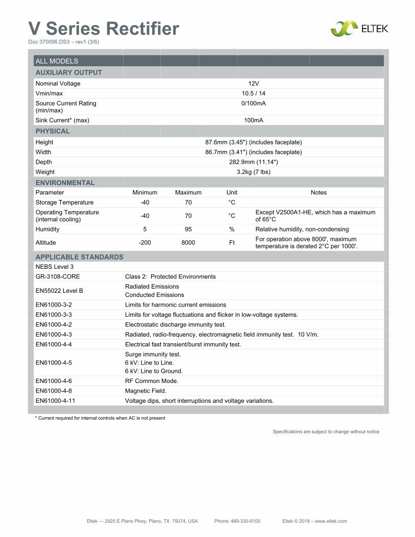
ALL MODELS
AUXILIARY OUTPUT
Nominal Voltage 12V
Vmin/max 10.5 / 14
Source Current Rating (min/max)
0/100mA
Sink Current* (max) 100mA
PHYSICAL
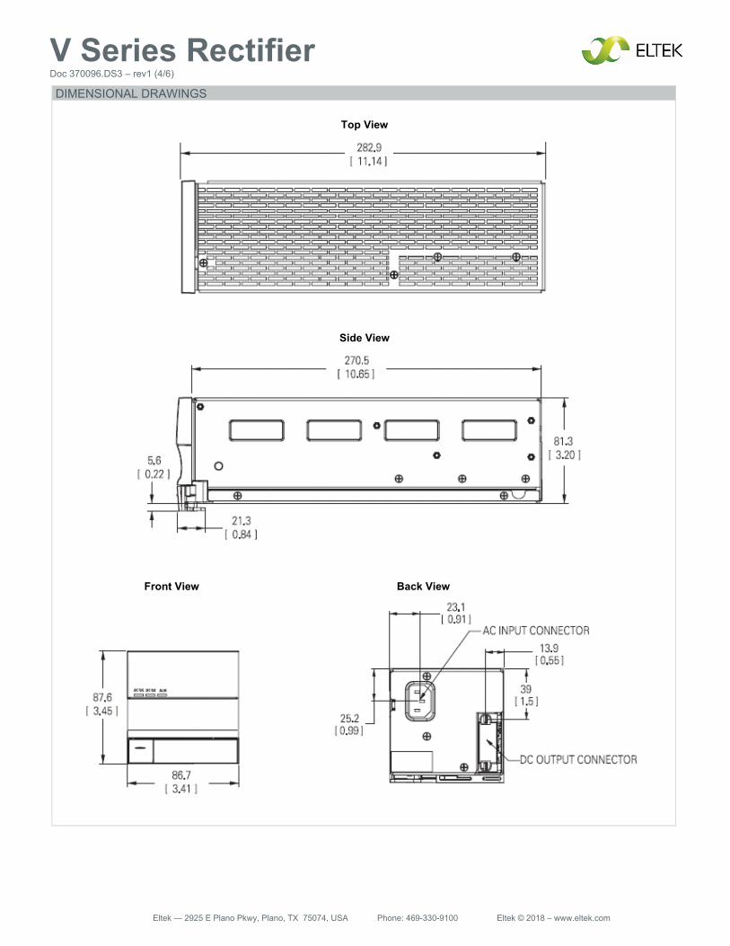
Height 87.6mm (3.45") (includes faceplate)
Width 86.7mm (3.41") (includes faceplate)
Depth 282.9mm (11.14")
Weight 3.2kg (7 lbs)
ENVIRONMENTAL
Parameter Minimum Maximum Unit Notes
Storage Temperature -40 70 °C
Operating Temperature (internal cooling) -40 70 °C Except V2500A1-HE, which has a maximum
of 65°C
Humidity 5 95 % Relative humidity, non-condensing
Altitude -200 8000 Ft For operation above 8000', maximum temperature is derated 2°C per 1000'.
APPLICABLE STANDARDS
NEBS Level 3
GR-3108-CORE Class 2: Protected Environments
EN55022 Level B
Radiated Emissions Conducted Emissions
EN61000-3-2 Limits for harmonic current emissions
EN61000-3-3 Limits for voltage fluctuations and flicker in low-voltage systems.
EN61000-4-2 Electrostatic discharge immunity test.
EN61000-4-3 Radiated, radio-frequency, electromagnetic field immunity test. 10 V/m.
EN61000-4-4 Electrical fast transient/burst immunity test.
EN61000-4-5
Surge immunity test. 6 kV: Line to Line. 6 kV: Line to Ground.
EN61000-4-6 RF Common Mode.
EN61000-4-8 Magnetic Field.
EN61000-4-11 Voltage dips, short interruptions and voltage variations.
* Current required for internal controls when AC is not present
Specifications are subject to change without notice
Eltek — 2925 E Plano Pkwy, Plano, TX 75074, USA Phone: 469-330-9100 Eltek © 2018 – www.eltek.com
V Series Rectifier Doc 370096.DS3 – rev1 (4/6)
Top View
Side View
DIMENSIONAL DRAWINGS
Front View Back View
Eltek — 2925 E Plano Pkwy, Plano, TX 75074, USA Phone: 469-330-9100 Eltek © 2018 – www.eltek.com
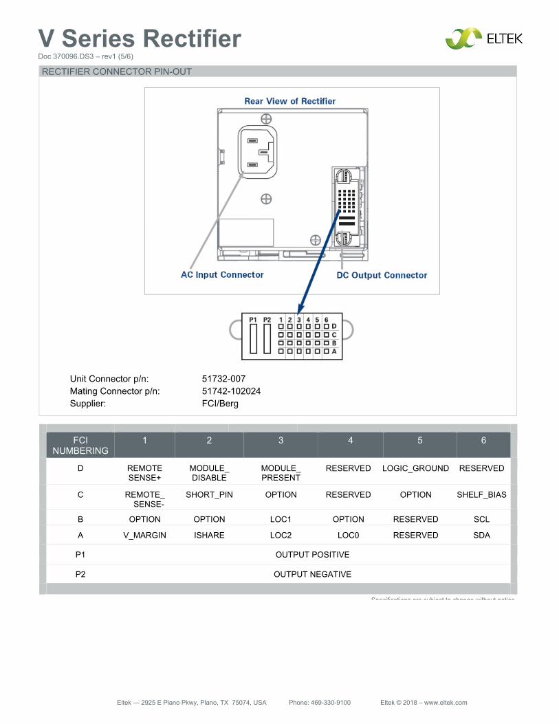
V Series Rectifier Doc 370096.DS3 – rev1 (5/6)
FCI NUMBERING
1 2 3 4 5 6
D REMOTE SENSE+
MODULE_ DISABLE
MODULE_ PRESENT
RESERVED LOGIC_GROUND RESERVED
C REMOTE_ SENSE-
SHORT_PIN OPTION RESERVED OPTION SHELF_BIAS
B OPTION OPTION LOC1 OPTION RESERVED SCL
A V_MARGIN ISHARE LOC2 LOC0 RESERVED SDA
P1 OUTPUT POSITIVE
P2 OUTPUT NEGATIVE
Specifications are subject to change without notice
Unit Connector p/n: 51732-007 Mating Connector p/n: 51742-102024 Supplier: FCI/Berg
RECTIFIER CONNECTOR PIN-OUT
Eltek — 2925 E Plano Pkwy, Plano, TX 75074, USA Phone: 469-330-9100 Eltek © 2018 – www.eltek.com
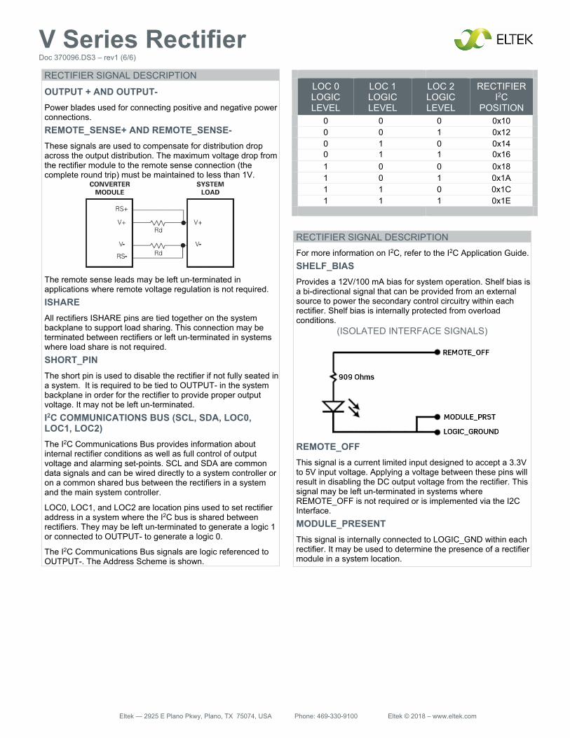
V Series Rectifier Doc 370096.DS3 – rev1 (6/6)
LOC 0 LOGIC LEVEL
LOC 1 LOGIC LEVEL
LOC 2 LOGIC LEVEL
RECTIFIER I2C
POSITION
0 0 0 0x10 0 0 1 0x12 0 1 0 0x14 0 1 1 0x16 1 0 0 0x18 1 0 1 0x1A 1 1 0 0x1C 1 1 1 0x1E
RECTIFIER SIGNAL DESCRIPTION
OUTPUT + AND OUTPUT- Power blades used for connecting positive and negative power connections. REMOTE_SENSE+ AND REMOTE_SENSE- These signals are used to compensate for distribution drop across the output distribution. The maximum voltage drop from the rectifier module to the remote sense connection (the complete round trip) must be maintained to less than 1V.
The remote sense leads may be left un-terminated in applications where remote voltage regulation is not required. ISHARE All rectifiers ISHARE pins are tied together on the system backplane to support load sharing. This connection may be terminated between rectifiers or left un-terminated in systems where load share is not required. SHORT_PIN The short pin is used to disable the rectifier if not fully seated in a system. It is required to be tied to OUTPUT- in the system backplane in order for the rectifier to provide proper output voltage. It may not be left un-terminated. I2C COMMUNICATIONS BUS (SCL, SDA, LOC0, LOC1, LOC2) The I2C Communications Bus provides information about internal rectifier conditions as well as full control of output voltage and alarming set-points. SCL and SDA are common data signals and can be wired directly to a system controller or on a common shared bus between the rectifiers in a system and the main system controller.
LOC0, LOC1, and LOC2 are location pins used to set rectifier address in a system where the I2C bus is shared between rectifiers. They may be left un-terminated to generate a logic 1 or connected to OUTPUT- to generate a logic 0.
The I2C Communications Bus signals are logic referenced to OUTPUT-. The Address Scheme is shown.
RECTIFIER SIGNAL DESCRIPTION For more information on I2C, refer to the I2C Application Guide. SHELF_BIAS Provides a 12V/100 mA bias for system operation. Shelf bias is a bi-directional signal that can be provided from an external source to power the secondary control circuitry within each rectifier. Shelf bias is internally protected from overload conditions.
(ISOLATED INTERFACE SIGNALS)
REMOTE_OFF This signal is a current limited input designed to accept a 3.3V to 5V input voltage. Applying a voltage between these pins will result in disabling the DC output voltage from the rectifier. This signal may be left un-terminated in systems where REMOTE_OFF is not required or is implemented via the I2C Interface. MODULE_PRESENT This signal is internally connected to LOGIC_GND within each rectifier. It may be used to determine the presence of a rectifier module in a system location.