Embed Size (px)
Citation preview
GSJ: Volume 6, Issue 12, December 2018, Online: ISSN 2320-9186
www.globalscientificjournal.com
VALUE ENGINEERING IN PIPING DESIGN BALAJI VIJAYAKUMAR, SIVA EKAMBARAM, RANJITH SANKARAN Piping Stress Engineer, Fluor Daniel India Private Limited, Gurugram, India.
Abstract
With the current market scenario, all the projects that we do are highly dependant on Total
installed cost and are Schedule driven. And to help us meet this crucial deadline, we are utilizing
various technologies and high-end software’s. But seldom we innovate or seek new ideas to find
alternate solutions to problems. In this paper we are talking about two ideas, by thinking out of the
box, which we had implemented in our current project. One is about converting the 3D loop in a
steam line to flat loop and another about locating transportation support to eliminate the additional
scaffolding.
—————————— ——————————
Value Engineering Idea 1: Piperack steam lines 3D loop vs Flat loop.
As per the normal Engineering practice, the initial design of the Steam lines in the Piperack were with the 3D loop. The line sizes involved were in the range of 900 NB to 1600 NB. Considering the huge line sizes, by providing 3D loop the rack height was also very high. Then we examined the preliminary piperack section drawing and we found only two steam lines were located on the fourth Tier, due to the interface with other contractors. Providing a 3D loop at this elevation is go-ing to further increase the pierack height by almost 2.5 m. Low Pressure Steam Line properities: Line size: 1600 NB Design Temp: 235 deg c Design Pressure: 0.6 N/mm2 Material: A672-C60 CA: 1 mm Thickness: 15.880 mm Length: Approximately 450 Meters in N-S Pipe rack Thermal Expansion co-efficient: 2.673 mm/m Total Expansion: 1200 mm No of loops required: 3 (ie considering Max of 400 mm expansion in Loop) Medium Pressure Steam Line properities: Line size: 900 NB Design Temp: 400 deg c Design Pressure: 3.45 N/mm2 Material: A672-C60 CA: 1 mm Thickness: 19.050 mm
GSJ: Volume 6, Issue 12, December 2018 ISSN 2320-9186
189
GSJ© 2018 www.globalscientificjournal.com
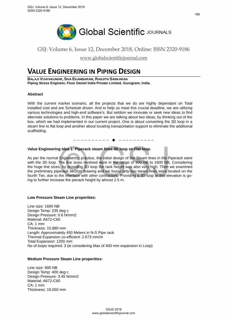
Length: Approximately 450 Meters in N-S Pipe rack Thermal Expansion co-efficient: 5.152 mm/m Total Expansion: 2318 No of loops required: 5 (ie considering Max of 400 mm expansion in Loop) Preliminary Design with 3D loop stress was within allowable range and calculated maximum stress was 214 N/mm2 where allowable is 238N/mm2 and perentage is 90% @ last loop location. Figure A and B depecits the preliminary design for steam lines.
Figure A ( Elevation View )
Figure B (Plan View)
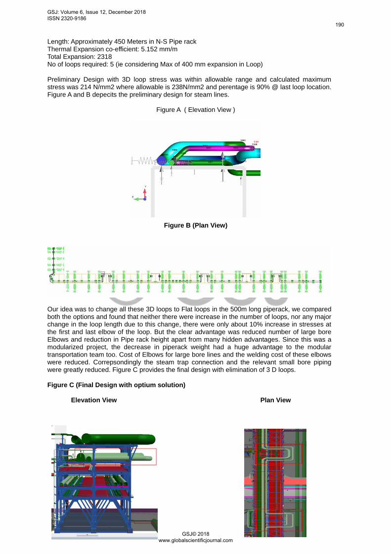
Our idea was to change all these 3D loops to Flat loops in the 500m long piperack, we compared both the options and found that neither there were increase in the number of loops, nor any major change in the loop length due to this change, there were only about 10% increase in stresses at the first and last elbow of the loop. But the clear advantage was reduced number of large bore Elbows and reduction in Pipe rack height apart from many hidden advantages. Since this was a modularized project, the decrease in piperack weight had a huge advantage to the modular transportation team too. Cost of Elbows for large bore lines and the welding cost of these elbows were reduced. Correpsondingly the steam trap connection and the relevant small bore piping were greatly reduced. Figure C provides the final design with elimination of 3 D loops. Figure C (Final Design with optium solution)
Elevation View Plan View
GSJ: Volume 6, Issue 12, December 2018 ISSN 2320-9186
190
GSJ© 2018 www.globalscientificjournal.com

COST SAVING: This idea helped us in reducing the Total Installed Cost, a rough order of magni-tude is provided below for reference on piping material / fabrication cost.
Rough magnitude estimate of Cost saved
Pipe Rack Flat Loop In Steam Lines
Component Size in NB Qty Cost per Qty Total Cost
Elbow 900 10 $2,315 $23150 Elbow weld / pre fabrica-
tion cost 900 10 $2,050 $20500 Elbow 1600 6 $11,170 $67020 Elbow weld / pre fabrica-
tion cost 1600 6 $2,430 $14580 Steam Trap cost
32 $60 $1,920
Total Saving
$127170
Note : Cost not included in above estimate Small bore piping from drip leg to steam trap and supporting cost not included
Overall Strucutre Height reduced by 2.5 meters ( ie around 500meter length )
GSJ: Volume 6, Issue 12, December 2018 ISSN 2320-9186
191
GSJ© 2018 www.globalscientificjournal.com
Value Engineering Idea 2: Locating Transportation Support to avoid additional scaffolding.
In one of our recent project, we had 133 Pipe rack modules (or Pre-Assembled Rack – PAR),
and as per normal procedure the transportation supports were provided at multiple locations in
staggered manner. Temporary supports used during transportation must be designed for fatigue
characteristics, adequate strength to resist the dynamic loading. Temporary Supports should be
painted with bright fluorescent color coding for easy identification and removal at job-site.This
called for rising scaffolding again at Site to remove these transportation supports and few trans-
portation supports were practically in inaccessible location.
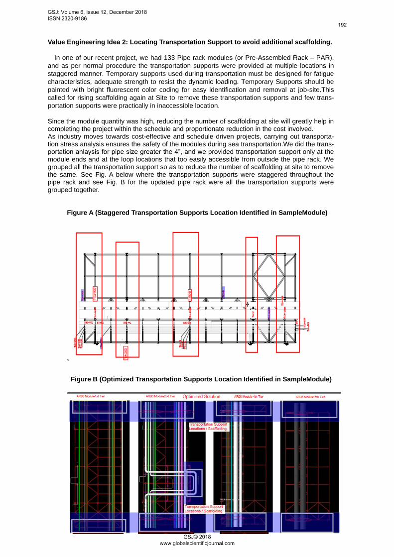
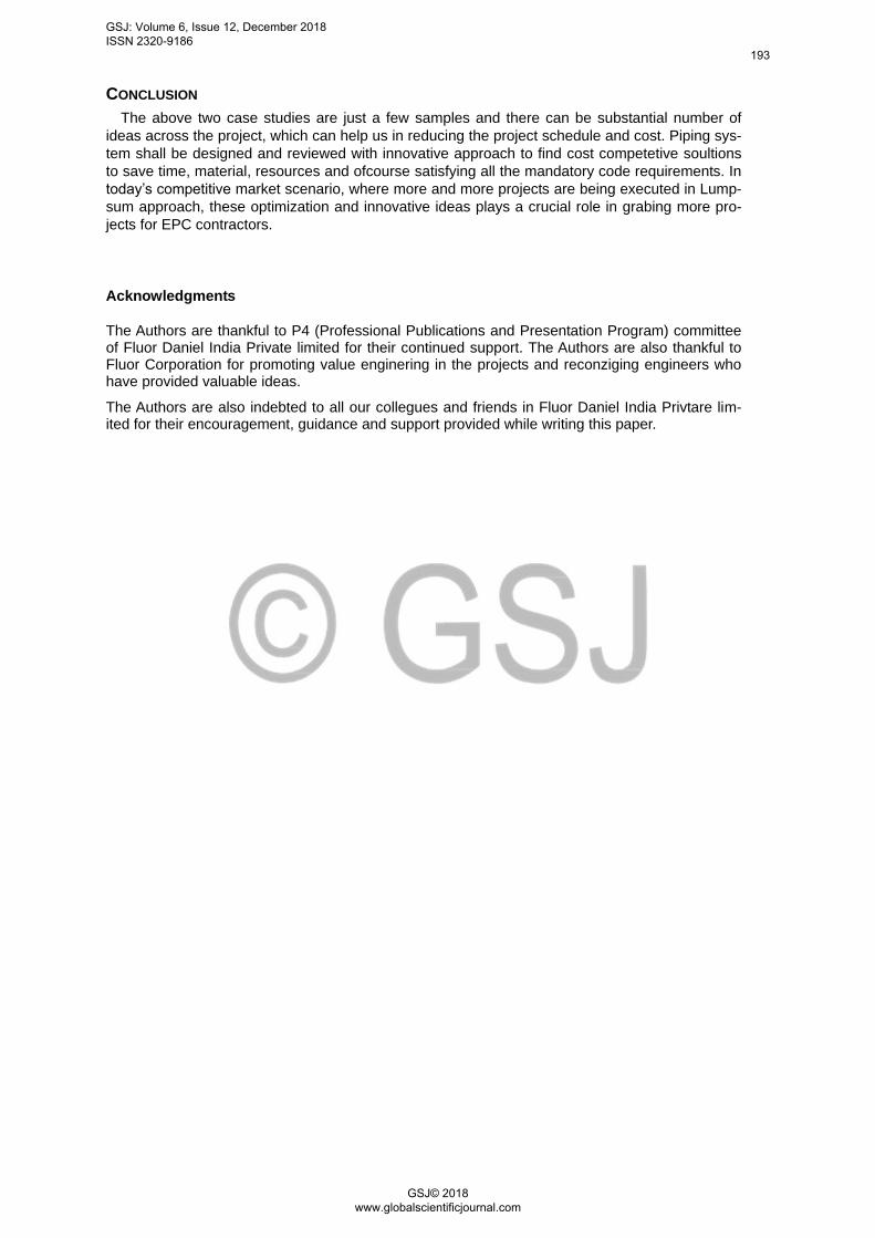
Since the module quantity was high, reducing the number of scaffolding at site will greatly help in completing the project within the schedule and proportionate reduction in the cost involved. As industry moves towards cost-effective and schedule driven projects, carrying out transporta-tion stress analysis ensures the safety of the modules during sea transportation.We did the trans-portation anlaysis for pipe size greater the 4”, and we provided transportation support only at the module ends and at the loop locations that too easily accessible from outside the pipe rack. We grouped all the transportation support so as to reduce the number of scaffolding at site to remove the same. See Fig. A below where the transportation supports were staggered throughout the pipe rack and see Fig. B for the updated pipe rack were all the transportation supports were grouped together.
Figure A (Staggered Transportation Supports Location Identified in SampleModule)
Figure B (Optimized Transportation Supports Location Identified in SampleModule)
GSJ: Volume 6, Issue 12, December 2018 ISSN 2320-9186
192
GSJ© 2018 www.globalscientificjournal.com
CONCLUSION
The above two case studies are just a few samples and there can be substantial number of
ideas across the project, which can help us in reducing the project schedule and cost. Piping sys-
tem shall be designed and reviewed with innovative approach to find cost competetive soultions
to save time, material, resources and ofcourse satisfying all the mandatory code requirements. In
today’s competitive market scenario, where more and more projects are being executed in Lump-
sum approach, these optimization and innovative ideas plays a crucial role in grabing more pro-
jects for EPC contractors.
Acknowledgments
The Authors are thankful to P4 (Professional Publications and Presentation Program) committee of Fluor Daniel India Private limited for their continued support. The Authors are also thankful to Fluor Corporation for promoting value enginering in the projects and reconziging engineers who have provided valuable ideas.
The Authors are also indebted to all our collegues and friends in Fluor Daniel India Privtare lim-ited for their encouragement, guidance and support provided while writing this paper.
GSJ: Volume 6, Issue 12, December 2018 ISSN 2320-9186
193
GSJ© 2018 www.globalscientificjournal.com