Embed Size (px)
Citation preview
RTM Engineering
Calculations Client Getrich Development Use in correspondences
Project Deepdown Sands 234 010455
Location Up in the North Dept Job Reference
Subject Foundation for Piperack Design Doc No P23-00455-C103A Rev 0
Page 1 of 42
RTM
2.0 “CALCULATIONS ”: INDEX
ITEM
DESCRIPTION SHEET TAB
2.0 INDEX 1
2.1 DESCRIPTION OF CONSTRUCTION 2
2.2 STRUCTURAL MODEL 3
2.3 LOADING 4
2.4 PAVING LOADS 5
2.5 SUPPORT STIFFNESS 6
2.6 THE PIPERACK 7
2.7 THE AIRCOOLERS 10
2.8 STEELWORK SUPPORT STRUCTURES 14
2.9 WIND LOADING 17
2.10 LOAD CASE SUMMARY 21
2.11 PILE LOAD SUMMARY 22
2.12 SUPPORT REACTIONS - STAAD ANALYSIS 25
RTM Engineering
Calculations Client Getrich Development Use in correspondences
Project Deepdown Sands 234 010455
Location Up in the North Dept Job Reference
Subject Foundation for Piperack Design Doc No P23-00455-C103A Rev 0
Page 2 of 42
RTM
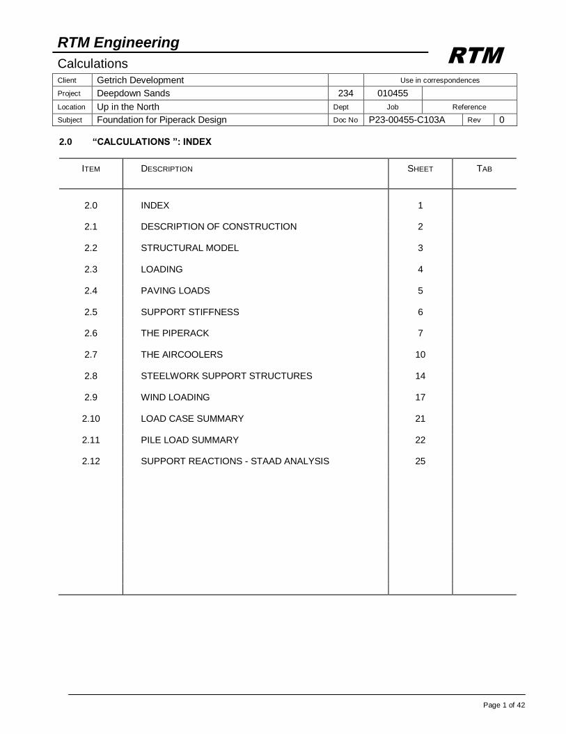
2.1 DESCRIPTION OF CONSTRUCTION
The piperack: 10 m span RC piperack structure, 15 bays at 6 m c/c orientated E/W. RC frames connected longitudinally, TOC EL +105.750 and +111.500. TOS EL +108.250 and +103.250 RC column supported on a pile cap, modelled as a spring support. Pile caps are connected by a foundation slab of 3.0 m wide The pipe layers: EL.s + 104.500, + 107.500 and + 110.250. Intermediate steel is provided in tranverse direction to similar levels
Steelwork Support Structure A
E
1471
Steelwork Support Structure C
Steelwork Support Structure B
N 4571
N 4561
N 4576
N
4554
Safety Valve Platform
E
1561
Shading indicate Platforms
Bold Lines refer to RC sections
y x
z
RTM Engineering
Calculations Client Getrich Development Use in correspondences
Project Deepdown Sands 234 010455
Location Up in the North Dept Job Reference
Subject Foundation for Piperack Design Doc No P23-00455-C103A Rev 0
Page 3 of 42
RTM
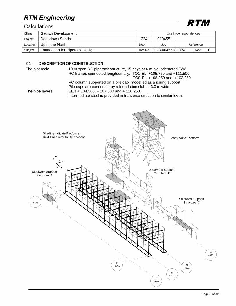
2.2 STRUCTURAL MODEL
Section on E.1495.0
Section on E.1471.0 With typical sections
Section on E.1501.0 Section on E.1477.0
Section on E.1507.0 Section on E.1483.0
Section on E.1513.0 Section on E.1489.0
Section on
N.4576.0
E.
1471
HPP EL +100.000
TOS EL +124.090 TOS EL +120.340 TOS EL +113.570 TOS EL +108.250
TOS EL +104.500
TOS EL +103.250
TOS EL +120.475
TOS EL +116.975
TOS EL +111.125
TOS EL +108.250
TOS EL +110.400
E.
1555
SLIDING CONNECTION
Section on N.4571.0
E.
1561 E.
1471
TOS EL +120.340
TOC EL +111.500
TOS EL +108.250
TOC EL +105.750
TOS EL +103.250
TOC EL +114.000
TOS EL +131.500 TOS EL +129.750
TOS EL +124.350
TOS EL +118.800
Section on N.4561.0
E.
1471
Concrete components Columns 700 x 700 Transverse beams 700W x 900 dp Longitudinal beams 500W x 700 dp
Section on E.1531.0 Section on E.1537.0 Section on E.1543.0 Section on E.1549.0
SLIDING CONNECTION
Section on N.4556.0
E.
1471
Intermediate Sections not
shown fabricated from HE300A
HE240A (typ)
HE240A (typ)
900dp x 700W
900dp x 700W
HE400A
700 x
700
RTM Engineering
Calculations Client Getrich Development Use in correspondences
Project Deepdown Sands 234 010455
Location Up in the North Dept Job Reference
Subject Foundation for Piperack Design Doc No P23-00455-C103A Rev 0
Page 4 of 42
RTM
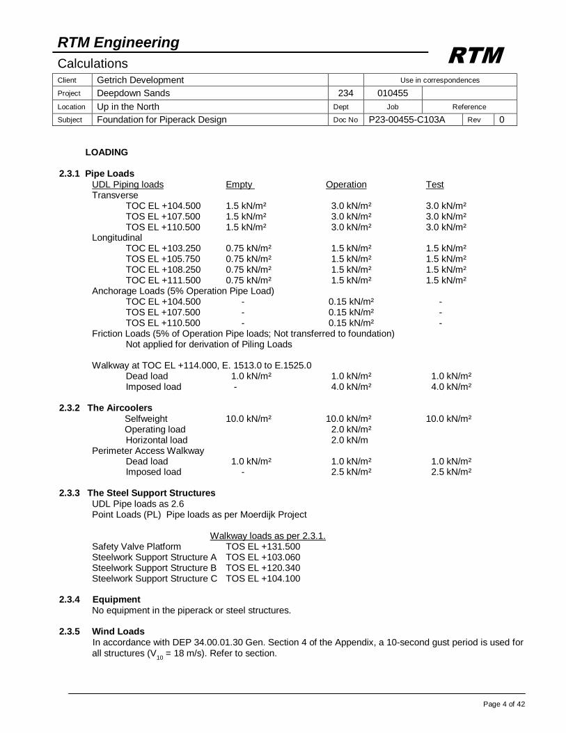
LOADING
2.3.1 Pipe Loads UDL Piping loads Empty Operation Test Transverse TOC EL +104.500 1.5 kN/m² 3.0 kN/m² 3.0 kN/m² TOS EL +107.500 1.5 kN/m² 3.0 kN/m² 3.0 kN/m² TOS EL +110.500 1.5 kN/m² 3.0 kN/m² 3.0 kN/m² Longitudinal TOC EL +103.250 0.75 kN/m² 1.5 kN/m² 1.5 kN/m² TOS EL +105.750 0.75 kN/m² 1.5 kN/m² 1.5 kN/m² TOC EL +108.250 0.75 kN/m² 1.5 kN/m² 1.5 kN/m² TOC EL +111.500 0.75 kN/m² 1.5 kN/m² 1.5 kN/m² Anchorage Loads (5% Operation Pipe Load) TOC EL +104.500 - 0.15 kN/m² - TOS EL +107.500 - 0.15 kN/m² - TOS EL +110.500 - 0.15 kN/m² - Friction Loads (5% of Operation Pipe loads; Not transferred to foundation) Not applied for derivation of Piling Loads Walkway at TOC EL +114.000, E. 1513.0 to E.1525.0 Dead load 1.0 kN/m² 1.0 kN/m² 1.0 kN/m² Imposed load - 4.0 kN/m² 4.0 kN/m² 2.3.2 The Aircoolers Selfweight 10.0 kN/m² 10.0 kN/m² 10.0 kN/m² Operating load 2.0 kN/m² Horizontal load 2.0 kN/m Perimeter Access Walkway Dead load 1.0 kN/m² 1.0 kN/m² 1.0 kN/m² Imposed load - 2.5 kN/m² 2.5 kN/m² 2.3.3 The Steel Support Structures UDL Pipe loads as 2.6 Point Loads (PL) Pipe loads as per Moerdijk Project Walkway loads as per 2.3.1. Safety Valve Platform TOS EL +131.500 Steelwork Support Structure A TOS EL +103.060 Steelwork Support Structure B TOS EL +120.340 Steelwork Support Structure C TOS EL +104.100 2.3.4 Equipment No equipment in the piperack or steel structures. 2.3.5 Wind Loads
In accordance with DEP 34.00.01.30 Gen. Section 4 of the Appendix, a 10-second gust period is used for all structures (V
10 = 18 m/s). Refer to section.
RTM Engineering
Calculations Client Getrich Development Use in correspondences
Project Deepdown Sands 234 010455
Location Up in the North Dept Job Reference
Subject Foundation for Piperack Design Doc No P23-00455-C103A Rev 0
Page 5 of 42
RTM
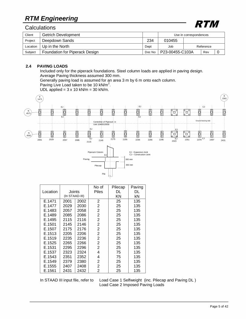
2.4 PAVING LOADS Included only for the piperack foundations. Steel column loads are applied in paving design. Average Paving thickness assumed 300 mm. Generally paving load is assumed for an area 3 m by 6 m onto each column. Paving Live Load taken to be 10 kN/m
2.
UDL applied = 3 x 10 kN/m = 30 kN/m.
Location
Joints
(In STAAD-III)
No of Piles
Pilecap DL KN
Paving DL kN
E.1471 2001 2002 2 25 135 E.1477 2029 2030 2 25 135 E.1483 2057 2058 2 25 135 E.1489 2085 2086 2 25 135 E.1495 2115 2116 2 25 135 E.1501 2145 2146 2 25 135 E.1507 2175 2176 2 25 135 E.1513 2205 2206 2 25 135 E.1519 2235 2236 2 25 135 E.1525 2265 2266 2 25 135 E.1531 2295 2296 2 25 135 E.1537 2323 2324 4 75 135 E.1543 2351 2352 4 75 135 E.1549 2379 2380 2 25 135 E.1555 2407 2408 2 25 135 E.1561 2431 2432 2 25 135
In STAAD III input file, refer to Load Case 1 Selfweight (inc. Pilecap and Paving DL ) Load Case 2 Imposed Paving Loads
Centreline of Piperack in
Unit 10400/10500
CJ
CJ
Ground-bearing slab
350 mm
300 mm Paving
Piperack Column
Pilecap
Pile
EJ
EJ - Expansion Joint
CJ – Construction Joint
EJ
EJ
EJ
EJ
EJ
EJ
EJ
EJ
E
1471
E
1561
N
4561
N
4571
2001 2029 2057 2085 2115
2145 2175 2205 2235 2265 2295 2351 2407 2431 2323
2379
RTM Engineering
Calculations Client Getrich Development Use in correspondences
Project Deepdown Sands 234 010455
Location Up in the North Dept Job Reference
Subject Foundation for Piperack Design Doc No P23-00455-C103A Rev 0
Page 6 of 42
RTM
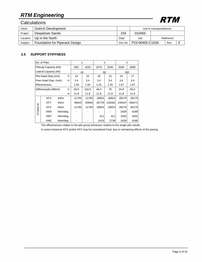
2.5 SUPPORT STIFFNESS
No. of Piles 1 2 4
Pilecap Capacity (kN) 835 1020 1670 2040 3340 4080
Lateral Capacity (kN) 40 80 160
Pile Head Disp.(mm) V 14 10 18 13 24 17
Free Head Disp. (mm) H 3.4 3.4 3.4 3.4 3.4 3.4
Effectiveness 1.00 1.00 1.25 1.25 1.67 1.67
Stiffness/pile (MN/m) V 59.6 102.0 46.4 78 34.8 60.0
H 11.8 11.8 11.8 11.8 11.8 11.8
S
TA
AD
-III
KFX kN/m 11765 11765 18824 18824 28179 28179
KFY kN/m 59643 83500 92778 128462 139167 196471
KFZ kN/m 11765 11765 18824 18824 28179 28179
KMX kNm/deg - - - - 2429 4189
KMY kNm/deg 411 411 1642 1642
KMZ kNm/deg - - 1619 2739 2429 4189
The effectiveness relates to the pile group behaviour relative to the single pile results
In some instances KFX and/or KFZ may be considered fixed, due to restraining effects of the paving.

RTM Engineering
Calculations Client Getrich Development Use in correspondences
Project Deepdown Sands 234 010455
Location Up in the North Dept Job Reference
Subject Foundation for Piperack Design Doc No P23-00455-C103A Rev 0
Page 7 of 42
RTM
THE PIPERACK Transverse sections, E. 1471 to E. 1561 Uniformly Distributed Load (UDL) On main sections UDL
pr = 2/3 x 6 m x 3.0 kN/m² = 12.0 kN/m
On intermediate sections UDL
pr = 1/3 x 6 m x 3.0 kN/m² = 6.0 kN/m
Walkway at TOC EL +114.000, E. 1513 to E.1525 UDL
pr = 8./10 x 3 x (4.0 + 1.0) = 12.0 kN/m
Longitudinal elevations, N. 4571 and N. 4561 UDL
pr = 1/4 x 10 x 1.5 = 3.75 kN/m
Walkway at TOC EL +114.000, E. 1471 to E.1441 UDL
pr = 1x (4.0 + 1.0) = 5.0 kN/m
Anchorage Forces carried on main RC beams in Z-direction on main sections at TOC EL+104.500, +107.00 and +110.250
UDLa = 0.15 kN/m² x 6 = 0.9 kN/m
Pipe Support Loads
Operation Test
Node Fx kN
Fy kN
Fz KN
Fy kN
Pip
era
ck
358 11 -29 12 -75
380 3 -17 4 -57
390 4 -42 12 -60
420 6 -26 5 -57
430 2 -16 3 -52
Table 1: Pipe Support Loads
Elevation on N4561 and N4571 For Pipe support nodes (only on N.4561) refer to Table 1
In STAAD III input file, refer to Load 3 Piperack Loads Load 4 Piperack Walkway Load 5 Anchorage Loads
For Steel Structure loading
refer to section 2.8.3
TOC EL +110.250
TOS EL +107.000
TOC EL +104.500
y
x
UDL 12 kN/m
UDL 12 kN/m
Typical Transverse Section PS node 358 on E.1537.0 refer to Table 1
UDL 12 kN/m
358
For Steel Structure loading
refer to section 2.8.1
y
z
TOC EL +114.000 TOC EL +111.500
TOS EL +108.250
TOC EL +105.750
TOS EL +103.250
HPP EL +100.000
For Aircooler Loads
refer to section 2.7
E 1471
UDL 3.75 kN/m
UDL 3.75 kN/m
UDL 3.75 kN/m
UDL 5 N/m
E
1561 E
1513
UDL 3.75 kN/m
For Steel Structure loading refer to section 2.8.2
420 430 380 390
RTM Engineering
Calculations Client Getrich Development Use in correspondences
Project Deepdown Sands 234 010455
Location Up in the North Dept Job Reference
Subject Foundation for Piperack Design Doc No P23-00455-C103A Rev 0
Page 8 of 42
RTM
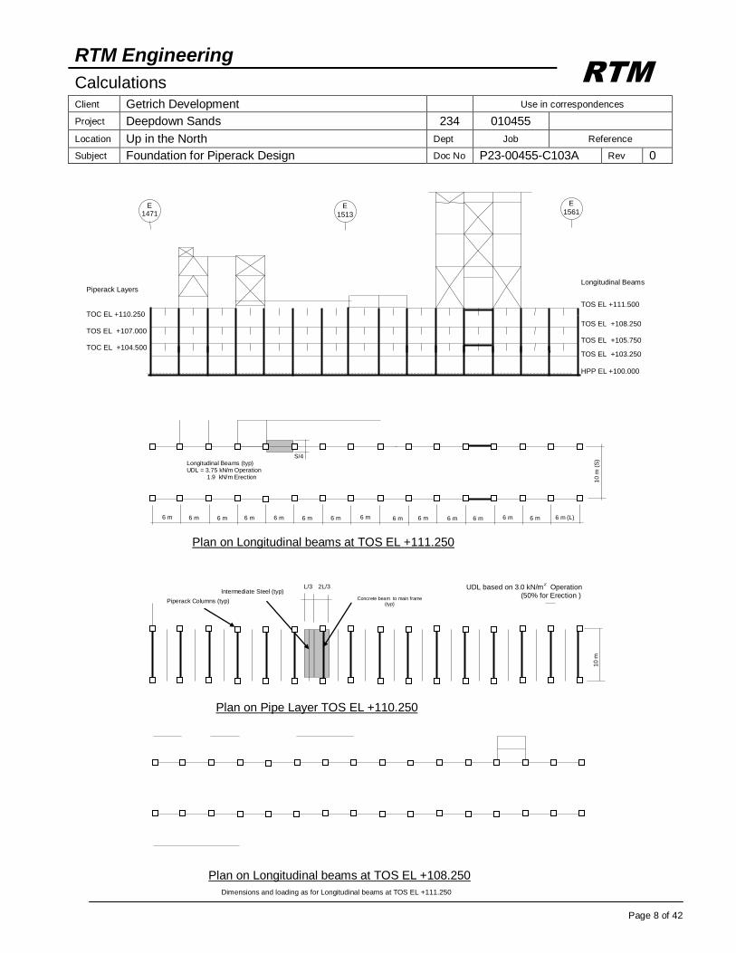
Longitudinal Beams
TOS EL +111.500
TOS EL +108.250
TOS EL +105.750
TOS EL +103.250
HPP EL +100.000
E 1471
E
1513
E
1561
Piperack Layers
TOC EL +110.250 TOS EL +107.000
TOC EL +104.500
UDL based on 3.0 kN/m2 Operation
(50% for Erection ) 1
0 m
Plan on Pipe Layer TOS EL +110.250
L/3 2L/3
Concrete beam to main frame (typ)
Intermediate Steel (typ)
Piperack Columns (typ)
6 m 6 m 6 m 6 m 6 m 6 m (L) 6 m 6 m 6 m 6 m 6 m 6 m 6 m 6 m
10
m (
S)
Plan on Longitudinal beams at TOS EL +111.250
S/4 Longitudinal Beams (typ) UDL = 3.75 kN/m Operation 1.9 kN/m Erection
6 m
Plan on Longitudinal beams at TOS EL +108.250
Dimensions and loading as for Longitudinal beams at TOS EL +111.250
RTM Engineering
Calculations Client Getrich Development Use in correspondences
Project Deepdown Sands 234 010455
Location Up in the North Dept Job Reference
Subject Foundation for Piperack Design Doc No P23-00455-C103A Rev 0
Page 9 of 42
RTM
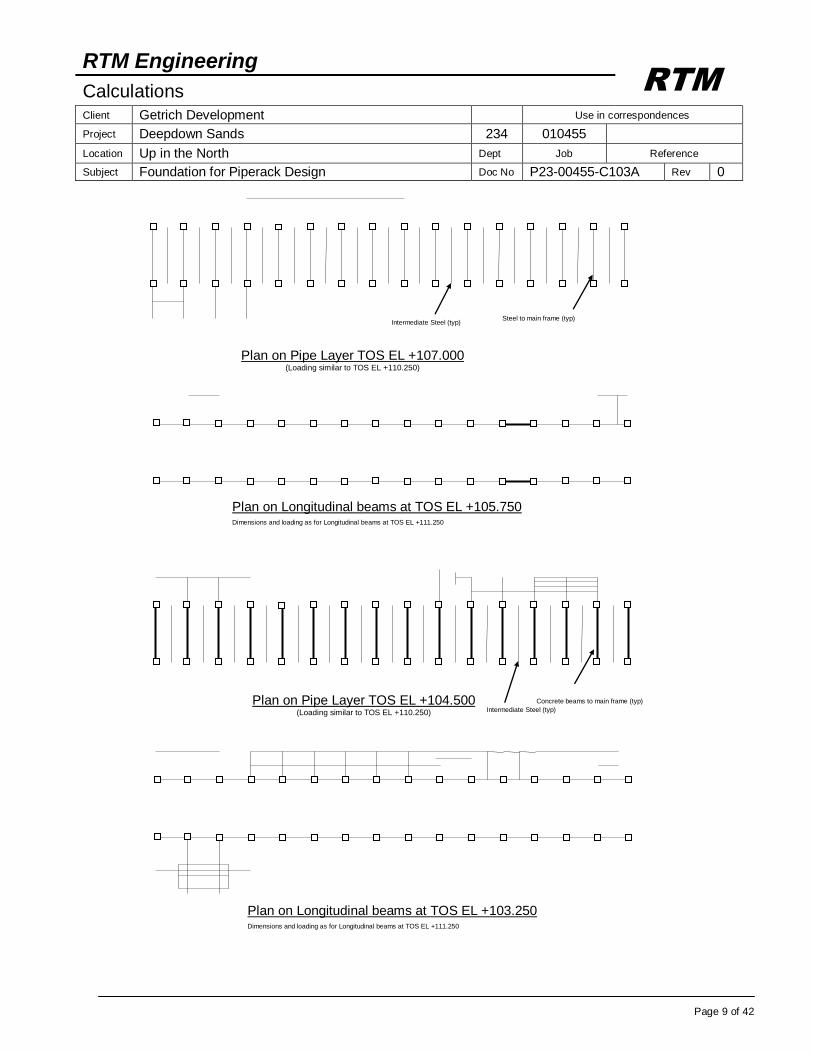
Plan on Pipe Layer TOS EL +107.000 (Loading similar to TOS EL +110.250)
Steel to main frame (typ) Intermediate Steel (typ)
Plan on Longitudinal beams at TOS EL +105.750 Dimensions and loading as for Longitudinal beams at TOS EL +111.250
Plan on Pipe Layer TOS EL +104.500 (Loading similar to TOS EL +110.250)
Concrete beams to main frame (typ)
Intermediate Steel (typ)
Plan on Longitudinal beams at TOS EL +103.250 Dimensions and loading as for Longitudinal beams at TOS EL +111.250
RTM Engineering
Calculations Client Getrich Development Use in correspondences
Project Deepdown Sands 234 010455
Location Up in the North Dept Job Reference
Subject Foundation for Piperack Design Doc No P23-00455-C103A Rev 0
Page 10 of 42
RTM
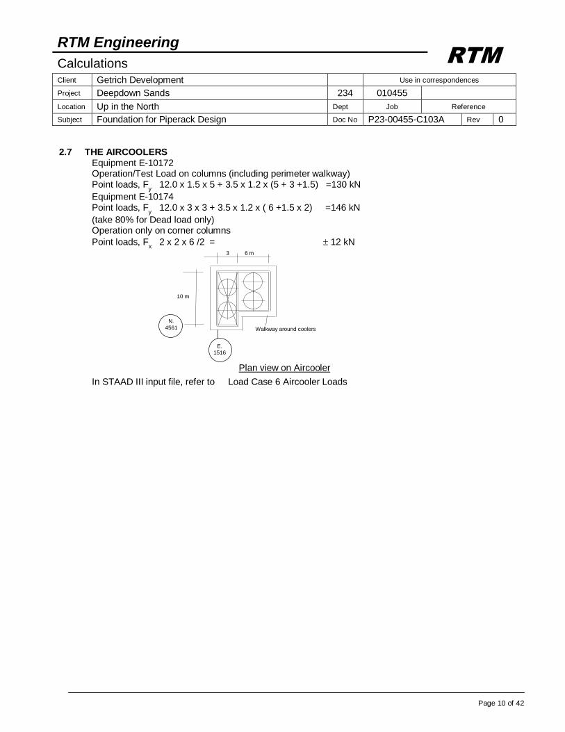
2.7 THE AIRCOOLERS Equipment E-10172 Operation/Test Load on columns (including perimeter walkway) Point loads, F
y 12.0 x 1.5 x 5 + 3.5 x 1.2 x (5 + 3 +1.5) =130 kN
Equipment E-10174 Point loads, F
y 12.0 x 3 x 3 + 3.5 x 1.2 x ( 6 +1.5 x 2) =146 kN
(take 80% for Dead load only) Operation only on corner columns
Point loads, Fx 2 x 2 x 6 /2 = 12 kN
In STAAD III input file, refer to Load Case 6 Aircooler Loads
Plan view on Aircooler
Walkway around coolers
10 m
3 6 m
E. 1516
N.
4561
RTM Engineering
Calculations Client Getrich Development Use in correspondences
Project Deepdown Sands 234 010455
Location Up in the North Dept Job Reference
Subject Foundation for Piperack Design Doc No P23-00455-C103A Rev 0
Page 11 of 42
RTM
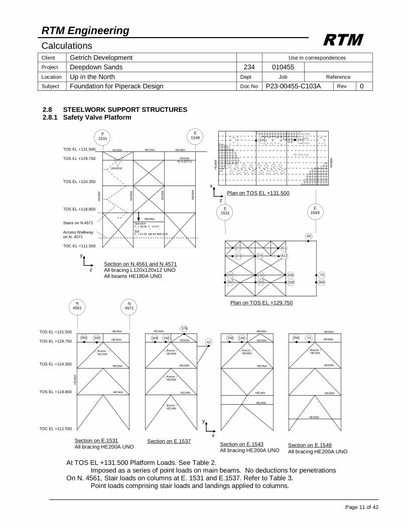
2.8 STEELWORK SUPPORT STRUCTURES 2.8.1 Safety Valve Platform
At TOS EL +131.500 Platform Loads. See Table 2. Imposed as a series of point loads on main beams. No deductions for penetrations On N. 4561, Stair loads on columns at E. 1531 and E.1537. Refer to Table 3. Point loads comprising stair loads and landings applied to columns.
HE
280A
HE300A
HE240A
HE240A
HE220A (typ)
HE
280A
376 414
Plan on TOS EL +131.500
356
74 100
250
150
300 350
200
373
374
411
412
60
Plan on TOS EL +129.750
Operation F
v = 28 kN F
h =0.3 F
v
Test F
v = 47 kN (90 kN N4571.0)
TOS EL +131.500 TOS EL +129.750 TOS EL +124.350 TOS EL +118.800 Stairs on N.4571 Access Walkway on N. 4571 TOC EL +111.550
Section on N.4561 and N.4571 All bracing L120x120x12 UNO All beams HE180A UNO
HE
280A
HE
280A
HE
280A
HE
280A
HE280A HE280A HE220A
HE280A
HE320A
0n N.4571.0
L90x90x9
E
1549 E
1531
E 1531
E 1549
y
z
x
z
100 250
Section on E.1543 All bracing HE200A UNO
HE260A
HE500A
HE240A
HE240A
HE240A
Braces HE260A
356 74
HE260A
HE300A
Braces HE220A
HE200A
HE200A
HE200A
Section on E.1549
All bracing HE200A UNO
42
376
150 300
Section on E.1537
HE200A
HE240A
HE500A
HE260A
Braces
HE260A
Braces HE200A
Braces HE240A
350 200
HE260A
HE
280A
HE300A
HE200A
HE240A
Section on E.1531
All bracing HE200A UNO
Braces
HE220A
TOS EL +131.500 TOS EL +129.750 TOS EL +124.350 TOS EL +118.800 TOC EL +111.550
N 4571
N 4561
y
x
376
RTM Engineering
Calculations Client Getrich Development Use in correspondences
Project Deepdown Sands 234 010455
Location Up in the North Dept Job Reference
Subject Foundation for Piperack Design Doc No P23-00455-C103A Rev 0
Page 12 of 42
RTM
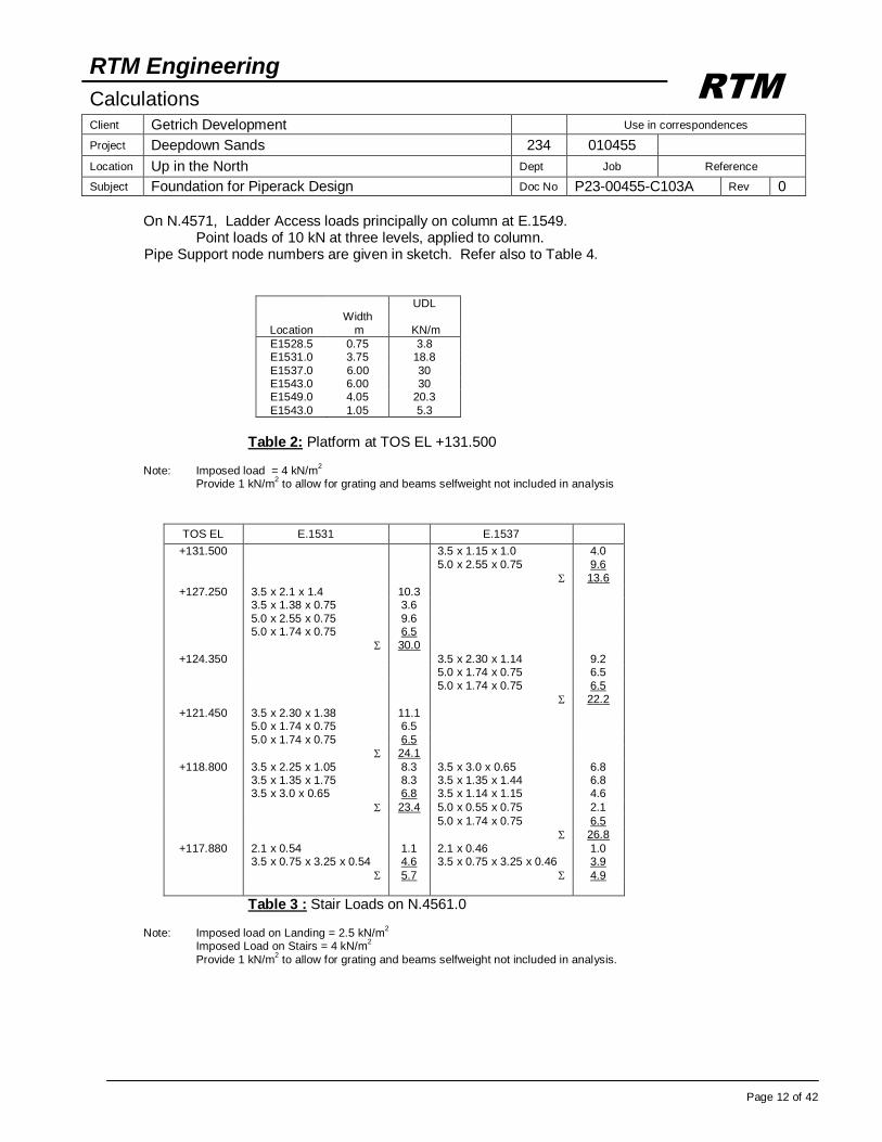
On N.4571, Ladder Access loads principally on column at E.1549. Point loads of 10 kN at three levels, applied to column. Pipe Support node numbers are given in sketch. Refer also to Table 4.
Width
UDL
Location m KN/m
E1528.5 0.75 3.8 E1531.0 3.75 18.8
E1537.0 6.00 30 E1543.0 6.00 30 E1549.0 4.05 20.3
E1543.0 1.05 5.3
Table 2: Platform at TOS EL +131.500 Note: Imposed load = 4 kN/m
2
Provide 1 kN/m2 to allow for grating and beams selfweight not included in analysis
TOS EL E.1531 E.1537
+131.500 3.5 x 1.15 x 1.0 4.0
5.0 x 2.55 x 0.75 9.6
13.6
+127.250 3.5 x 2.1 x 1.4 10.3 3.5 x 1.38 x 0.75 3.6
5.0 x 2.55 x 0.75 9.6 5.0 x 1.74 x 0.75 6.5
30.0
+124.350 3.5 x 2.30 x 1.14 9.2 5.0 x 1.74 x 0.75 6.5
5.0 x 1.74 x 0.75 6.5
22.2
+121.450 3.5 x 2.30 x 1.38 11.1 5.0 x 1.74 x 0.75 6.5
5.0 x 1.74 x 0.75 6.5
24.1
+118.800 3.5 x 2.25 x 1.05 8.3 3.5 x 3.0 x 0.65 6.8 3.5 x 1.35 x 1.75 8.3 3.5 x 1.35 x 1.44 6.8 3.5 x 3.0 x 0.65 6.8 3.5 x 1.14 x 1.15 4.6
23.4 5.0 x 0.55 x 0.75 2.1
5.0 x 1.74 x 0.75 6.5
26.8
+117.880 2.1 x 0.54 1.1 2.1 x 0.46 1.0 3.5 x 0.75 x 3.25 x 0.54 4.6 3.5 x 0.75 x 3.25 x 0.46 3.9
5.7 4.9
Table 3 : Stair Loads on N.4561.0 Note: Imposed load on Landing = 2.5 kN/m
2
Imposed Load on Stairs = 4 kN/m2
Provide 1 kN/m2 to allow for grating and beams selfweight not included in analysis.
RTM Engineering
Calculations Client Getrich Development Use in correspondences
Project Deepdown Sands 234 010455
Location Up in the North Dept Job Reference
Subject Foundation for Piperack Design Doc No P23-00455-C103A Rev 0
Page 13 of 42
RTM
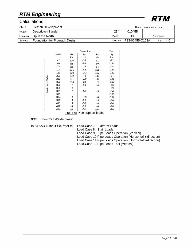
Operation Test
Node Fx kN
Fy kN
Fz KN
Fy kN
Sa
fety
V
alv
e P
latf
orm
42 10 -38 1 -92
60 5 -55 9 -184
74 8 -12 4 -24
100 11 -82 25 -124
150 20 -143 22 -182
200 12 -48 15 -67
250 11 -109 16 -146
300 14 -24 23 -100
350 3 -19 4 -46
356 2 -69
371 6 -36 3 -34
373 -100 374 2 -109 6 -102
376 7 -26 3 -94
411 2 -30 8 -94
412 1 -28 6 -96
414 3 -51 14 -96
Table 4: Pipe support loads Note: Reference Moerdijk Project
In STAAD III input file, refer to Load Case 7 Platform Loads Load Case 8 Stair Loads Load Case 9 Pipe Loads Operation (Vertical) Load Case 10 Pipe Loads Operation (Horizontal z-direction) Load Case 11 Pipe Loads Operation (Horizontal x-direction) Load Case 12 Pipe Loads Test (Vertical)
RTM Engineering
Calculations Client Getrich Development Use in correspondences
Project Deepdown Sands 234 010455
Location Up in the North Dept Job Reference
Subject Foundation for Piperack Design Doc No P23-00455-C103A Rev 0
Page 14 of 42
RTM
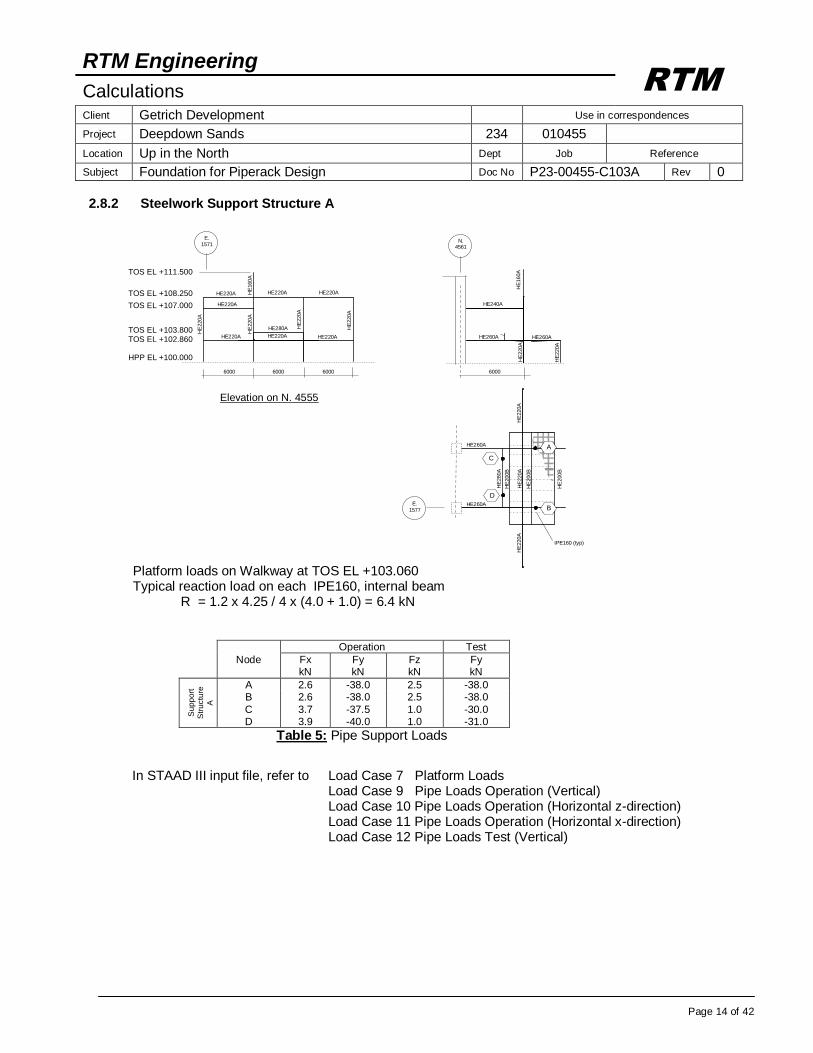
2.8.2 Steelwork Support Structure A
Platform loads on Walkway at TOS EL +103.060 Typical reaction load on each IPE160, internal beam
R = 1.2 x 4.25 / 4 x (4.0 + 1.0) = 6.4 kN
Operation Test
Node Fx kN
Fy kN
Fz kN
Fy kN
Su
pp
ort
S
tru
ctu
re
A
A 2.6 -38.0 2.5 -38.0 B 2.6 -38.0 2.5 -38.0
C 3.7 -37.5 1.0 -30.0 D 3.9 -40.0 1.0 -31.0
Table 5: Pipe Support Loads
In STAAD III input file, refer to Load Case 7 Platform Loads Load Case 9 Pipe Loads Operation (Vertical) Load Case 10 Pipe Loads Operation (Horizontal z-direction) Load Case 11 Pipe Loads Operation (Horizontal x-direction) Load Case 12 Pipe Loads Test (Vertical)
HE240A
HE260A HE260A
HE
220A
HE
220A
6000
N. 4561
HE
160A
HE
200B
HE
200B
HE
200B
HE
280A
E.
1577 H
E220A
H
E220A
H
E220A
HE260A
HE260A
TOS EL +111.500
TOS EL +108.250
TOS EL +107.000
TOS EL +103.800 TOS EL +102.860 HPP EL +100.000
HE220A HE220A HE220A
HE220A
HE280A
HE220A HE220A HE220A
HE
220A
HE
220A
HE
220A
HE
220A
E.
1571
6000 6000 6000
HE
160A
Elevation on N. 4555
A
B
C
D
IPE160 (typ)
RTM Engineering
Calculations Client Getrich Development Use in correspondences
Project Deepdown Sands 234 010455
Location Up in the North Dept Job Reference
Subject Foundation for Piperack Design Doc No P23-00455-C103A Rev 0
Page 15 of 42
RTM
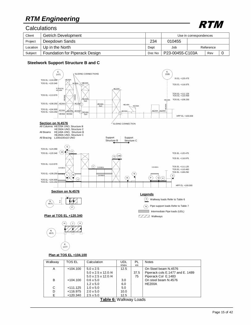
Steelwork Support Structure B and C
Walkway TOS EL Calculation UDL KN/m
PL kN
Notes
A +104.100 5.0 x 2.5 12.5 On Steel beam N.4576
5.0 x 2.5 x 12.0 /4 37.5 Piperack cols E.1477 and E. 1489 5.0 x 2.5 x 12.0 /4 75 Piperack Col E.1483
B +104.100 0.6 x 5.0 3.0 On steel beam N.4576
1.2 x 5.0 6.0 HE200A C +111.125 1.0 x 5.0 5.0 D +116.975 2.0 x 5.0 10.0
E +120.340 2.5 x 5.0 12.5
Table 6: Walkway Loads
Plan at TOS EL +104.100
Support
Structure C
Support
Structure B
F
G
N.
4571
5 m
Plan at TOS EL +120.340
H J K
N.
4571
E.
1477
E
Section on N.4576
HPP EL +100.000
TOS EL +124.090
TOS EL +120.340
TOS EL +113.570
TOS EL +108.250
TOS EL +104.500 TOS EL +103.250
TOS EL +120.475
TOS EL +116.975
TOS EL +111.125
TOS EL +108.250
TOS EL +110.400
E
25
A B
C
D 140
L N
P Q R S M
SLIDING CONNECTIONS
Section on N.4576 All Columns HE220A UNO, Structure B
HE260A UNO, Structure C All Beams HE140A UNO, Structure B
HE260A UNO, Structure C All Bracing L100x100x10 UNO
E.
1471
HPP EL +100.000
TOS EL +124.090
TOS EL +120.340
TOS EL +113.570
TOS EL +108.250
TOS EL +104.500
TOS EL +103.250
TOS EL +120.475
TOS EL +116.975
TOS EL +111.125
TOS EL +108.250
TOS EL +110.400
E.
1555
SLIDING CONNECTION
HE240A (typ)
HE240A
(typ)
HE220A
HE300A HE200A
HE200A
HE200A HE200A
HE300A
HE220A HE240A (typ)
HE220A K-Bracing HE140A
HE200A
HE
300A
HE
300A
HE300A
HE140A
HE
340A
HE240A
HE200A HE200A
HE200A
HE200A
B Walkway loads Refer to Table 6
Legends
N Pipe support loads Refer to Table 7 Intermediate Pipe loads (UDL)
Walkways
3.8 kN/m
3.8 kN/m
3.8 kN/m
3.8 kN/m 3.8 kN/m

RTM Engineering
Calculations Client Getrich Development Use in correspondences
Project Deepdown Sands 234 010455
Location Up in the North Dept Job Reference
Subject Foundation for Piperack Design Doc No P23-00455-C103A Rev 0
Page 16 of 42
RTM
Operation Test
Node Fx
kN
Fy
kN
Fz
kN
Fy
kN
Su
pp
ort
S
tru
ctu
re
B
25 13 -57 9 -130
140 2 -7 -7
E -88 -88
F -12 - -12
G -15 - -15
H 2.8 -16 2.5 -16
J 7.8 -36 11.5 -36
K 5 -21 9 -21
L 5.5 -20 3.5 -20
M 3 -14 3 -14
Su
pp
ort
S
tru
ctu
re
C
N -7 -7
P 2 -25 7 -25
Q 8 -37 32 -37
R -3 -3
S 2.7 -36 2.7 -36
Table 7: Pipe Support Loads In STAAD III input file, refer to Load Case 3 Piperack Loads Load Case 7 Platform Loads Load Case 9 Pipe Loads Operation (Vertical) Load Case 10 Pipe Loads Operation (Horizontal z-direction) Load Case 11 Pipe Loads Operation (Horizontal x-direction) Load Case 12 Pipe Loads Test (Vertical)
RTM Engineering
Calculations Client Getrich Development Use in correspondences
Project Deepdown Sands 234 010455
Location Up in the North Dept Job Reference
Subject Foundation for Piperack Design Doc No P23-00455-C103A Rev 0
Page 17 of 42
RTM
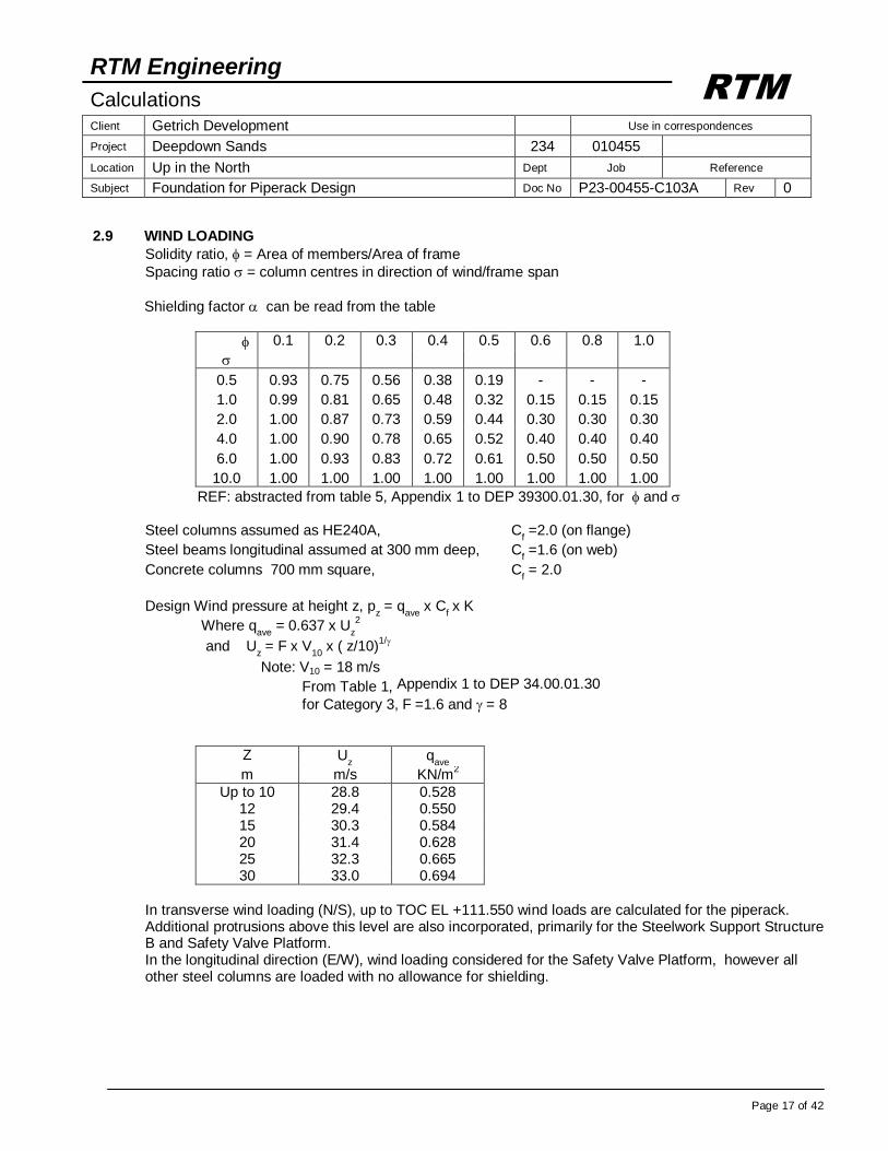
2.9 WIND LOADING
Solidity ratio, = Area of members/Area of frame
Spacing ratio = column centres in direction of wind/frame span
Shielding factor can be read from the table
0.1 0.2 0.3 0.4 0.5 0.6 0.8 1.0
0.5 0.93 0.75 0.56 0.38 0.19 - - -
1.0 0.99 0.81 0.65 0.48 0.32 0.15 0.15 0.15
2.0 1.00 0.87 0.73 0.59 0.44 0.30 0.30 0.30
4.0 1.00 0.90 0.78 0.65 0.52 0.40 0.40 0.40
6.0 1.00 0.93 0.83 0.72 0.61 0.50 0.50 0.50
10.0 1.00 1.00 1.00 1.00 1.00 1.00 1.00 1.00
REF: abstracted from table 5, Appendix 1 to DEP 39300.01.30, for and Steel columns assumed as HE240A, C
f =2.0 (on flange)
Steel beams longitudinal assumed at 300 mm deep, Cf =1.6 (on web)
Concrete columns 700 mm square, Cf = 2.0
Design Wind pressure at height z, p
z = q
ave x C
f x K
Where qave
= 0.637 x Uz
2
and Uz = F x V
10 x ( z/10)
1/
Note: V10 = 18 m/s
From Table 1, Appendix 1 to DEP 34.00.01.30
for Category 3, F =1.6 and = 8
Z Uz q
ave
m m/s KN/m2
Up to 10 28.8 0.528 12 29.4 0.550 15 30.3 0.584 20 31.4 0.628 25 32.3 0.665 30 33.0 0.694
In transverse wind loading (N/S), up to TOC EL +111.550 wind loads are calculated for the piperack. Additional protrusions above this level are also incorporated, primarily for the Steelwork Support Structure B and Safety Valve Platform. In the longitudinal direction (E/W), wind loading considered for the Safety Valve Platform, however all other steel columns are loaded with no allowance for shielding.
RTM Engineering
Calculations Client Getrich Development Use in correspondences
Project Deepdown Sands 234 010455
Location Up in the North Dept Job Reference
Subject Foundation for Piperack Design Doc No P23-00455-C103A Rev 0
Page 18 of 42
RTM
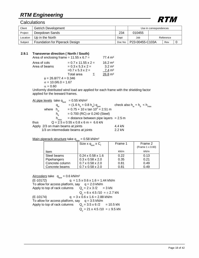
2.9.1 Transverse direction ( North / South)
Area of enclosing frame = 11.55 x 6.7 = 77.4 m²
Area of cols = 0.7 x 11.55 x 2 = 16.2 m² Area of beams = 0.3 x 5.3 x 2 = 3.2 m² =0.7 x 5.3 x 2 = 7.4 m²
Total area 26.8 m²
= 26.8/77.4 = 0.346
= 10.0/6.0 = 1.67
= 0.60 Uniformly distributed wind load are applied for each frame with the shielding factor
applied for the leeward frames.
At pipe levels take qave
= 0.55 kN/m²
qw = (1.6 h
b + 0.8 h
w) q
ave check also h
w + h
b < h
max
where hw = 0.75 + 10 x tan 10
o = 2.51 m
hb = 0.700 (RC) or 0.240 (Steel)
hmax
= distance between pipe layers = 2.5 m
thus Q = 2.5 x 0.55 x 0.8 x 6 m = 6.6 kN Apply 2/3 on main beams at joints 4.4 kN 1/3 on intermediate beams at joints 2.2 kN
Main piperack structure take q
ave = 0.58 kN/m²
Size x qave
x Cf
Frame 1
Frame 2 (Frame 1 x 0.60)
Item kN/m kN/m
Steel beams 0.24 x 0.58 x 1.6 0.22 0.13 Pipehangers 0.3 x 0.58 x 2.0 0.35 0.21 Concrete column 0.7 x 0.58 x 2.0 0.81 0.49 Concrete beams 0.7 x 0.58 x 2.0 0.81 0.49
Aircoolers take q
ave = 0.6 kN/m²
(E-10172) q = 1.5 x 0.6 x 1.6 = 1.44 kN/m To allow for access platform, say q = 2.0 kN/m Apply to top of rack columns Q
x = 2 x 3 /2 = 3 kN
Qy = 6 x 4.5 /10 = 2.7 kN
(E-10174) q = 3 x 0.6 x 1.6 = 2.88 kN/m To allow for access platform, say q = 3.5 kN/m Apply to top of rack columns Q
x = 3.5 x 6 /2 = 10.5 kN
Qy = 21 x 4.5 /10 = 9.5 kN
RTM Engineering
Calculations Client Getrich Development Use in correspondences
Project Deepdown Sands 234 010455
Location Up in the North Dept Job Reference
Subject Foundation for Piperack Design Doc No P23-00455-C103A Rev 0
Page 19 of 42
RTM
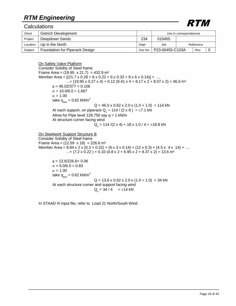
On Safety Valve Platform Consider Solidity of Steel frame Frame Area = (19.95 x 21.7) = 432.9 m² Member Area = [(21.7 x 0.28 + 6 x 0.22 + 6 x 0.32 + 8 x 6 x 0.14)] + .... ...+ (19.95 x 0.27 x 4) + 0.12 (9.41 x 4 + 8.17 x 2 + 8.07 x 2) = 46.0 m²
= 46.02/377 = 0.106
= 10.0/6.0 = 1.667
= 1.00 take q
ave = 0.62 kN/m
2
Q = 46.0 x 0.62 x 2.0 x (1.0 + 1.0) = 114 kN
At each support, on piperack Qx = 114 / (2 x 8 ) = 7.1 kN
Allow for Pipe level 129.750 say q = 1 kN/m At structure corner facing wind
Qx = 114 /(2 x 4) + 18 x 1.0 / 4 = 18.8 kN
On Steelwork Support Structure B Consider Solidity of Steel frame Frame Area = (12.59 x 18) = 226.6 m² Member Area = 8.84 x 2 x (0.3 + 0.22) + (6 x 3 x 0.14) + (12 x 0.3) + (4.5 x 4 x .14) + .... ...+ (7.2 x 0.22 ) + 0.10 (4.8 x 2 + 6.95 x 2 + 8.37 x 2) = 13.6 m²
= 13.6/226.6= 0.06
= 5.0/6.0 = 0.83
= 1.00 take q
ave = 0.62 kN/m
2
Q = 13.6 x 0.62 x 2.0 x (1.0 + 1.0) = 34 kN At each structure corner and support facing wind
Qx = 34 / 4 = 14 kN
In STAAD III input file, refer to Load 21 North/South Wind
RTM Engineering
Calculations Client Getrich Development Use in correspondences
Project Deepdown Sands 234 010455
Location Up in the North Dept Job Reference
Subject Foundation for Piperack Design Doc No P23-00455-C103A Rev 0
Page 20 of 42
RTM
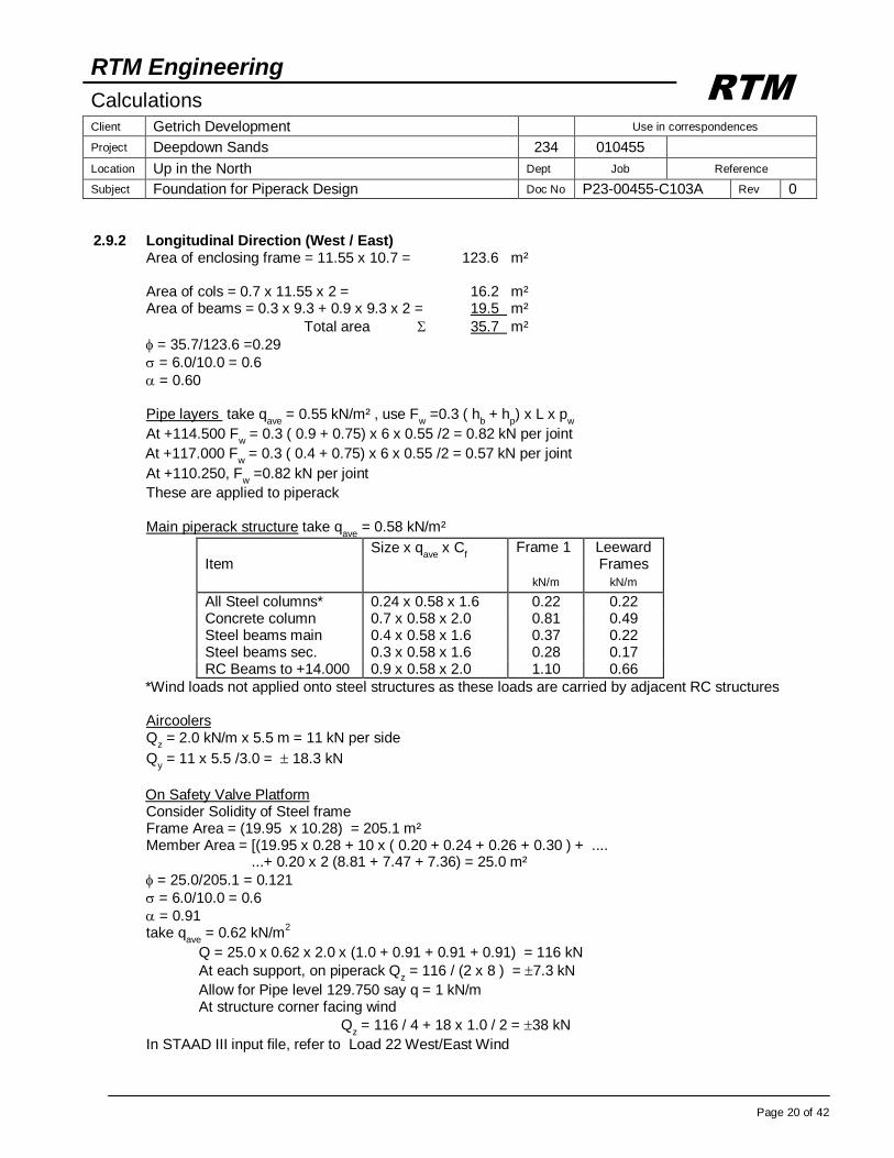
2.9.2 Longitudinal Direction (West / East)
Area of enclosing frame = 11.55 x 10.7 = 123.6 m² Area of cols = 0.7 x 11.55 x 2 = 16.2 m² Area of beams = 0.3 x 9.3 + 0.9 x 9.3 x 2 = 19.5 m²
Total area 35.7 m²
= 35.7/123.6 =0.29
= 6.0/10.0 = 0.6
= 0.60 Pipe layers take q
ave = 0.55 kN/m² , use F
w =0.3 ( h
b + h
p) x L x p
w
At +114.500 Fw = 0.3 ( 0.9 + 0.75) x 6 x 0.55 /2 = 0.82 kN per joint
At +117.000 Fw = 0.3 ( 0.4 + 0.75) x 6 x 0.55 /2 = 0.57 kN per joint
At +110.250, Fw =0.82 kN per joint
These are applied to piperack Main piperack structure take q
ave = 0.58 kN/m²
Item
Size x qave
x Cf
Frame 1
Leeward Frames
kN/m kN/m
All Steel columns* 0.24 x 0.58 x 1.6 0.22 0.22 Concrete column 0.7 x 0.58 x 2.0 0.81 0.49 Steel beams main 0.4 x 0.58 x 1.6 0.37 0.22 Steel beams sec. 0.3 x 0.58 x 1.6 0.28 0.17 RC Beams to +14.000 0.9 x 0.58 x 2.0 1.10 0.66
*Wind loads not applied onto steel structures as these loads are carried by adjacent RC structures Aircoolers Q
z = 2.0 kN/m x 5.5 m = 11 kN per side
Qy = 11 x 5.5 /3.0 = 18.3 kN
On Safety Valve Platform Consider Solidity of Steel frame Frame Area = (19.95 x 10.28) = 205.1 m² Member Area = [(19.95 x 0.28 + 10 x ( 0.20 + 0.24 + 0.26 + 0.30 ) + .... ...+ 0.20 x 2 (8.81 + 7.47 + 7.36) = 25.0 m²
= 25.0/205.1 = 0.121
= 6.0/10.0 = 0.6
= 0.91 take q
ave = 0.62 kN/m
2
Q = 25.0 x 0.62 x 2.0 x (1.0 + 0.91 + 0.91 + 0.91) = 116 kN
At each support, on piperack Qz = 116 / (2 x 8 ) = 7.3 kN
Allow for Pipe level 129.750 say q = 1 kN/m At structure corner facing wind
Qz = 116 / 4 + 18 x 1.0 / 2 = 38 kN
In STAAD III input file, refer to Load 22 West/East Wind
RTM Engineering
Calculations Client Getrich Development Use in correspondences
Project Deepdown Sands 234 010455
Location Up in the North Dept Job Reference
Subject Foundation for Piperack Design Doc No P23-00455-C103A Rev 0
Page 21 of 42
RTM
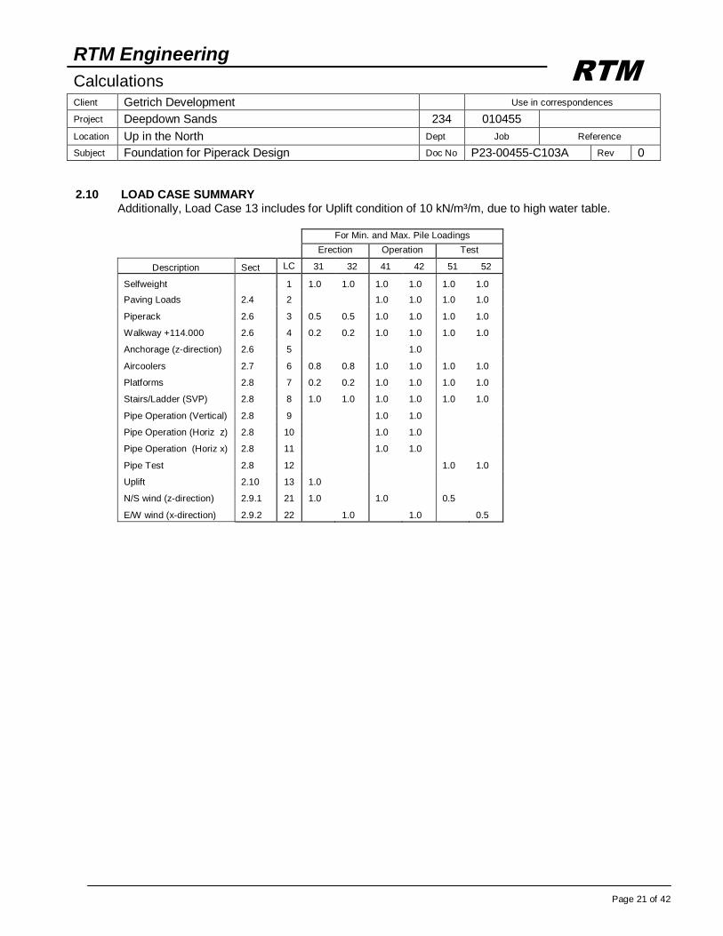
2.10 LOAD CASE SUMMARY
Additionally, Load Case 13 includes for Uplift condition of 10 kN/m³/m, due to high water table.
For Min. and Max. Pile Loadings
Erection Operation Test
Description Sect LC 31 32 41 42 51 52
Selfweight 1 1.0 1.0 1.0 1.0 1.0 1.0
Paving Loads 2.4 2 1.0 1.0 1.0 1.0
Piperack 2.6 3 0.5 0.5 1.0 1.0 1.0 1.0
Walkway +114.000
W
2.6 4 0.2 0.2 1.0 1.0 1.0 1.0
Anchorage (z-direction) 2.6 5 1.0
Aircoolers 2.7 6 0.8 0.8 1.0 1.0 1.0 1.0
Platforms 2.8 7 0.2 0.2 1.0 1.0 1.0 1.0
Stairs/Ladder (SVP) 2.8 8 1.0 1.0 1.0 1.0 1.0 1.0
Pipe Operation (Vertical) 2.8 9 1.0 1.0
Pipe Operation (Horiz z) 2.8 10 1.0 1.0
Pipe Operation (Horiz x) 2.8 11 1.0 1.0
Pipe Test 2.8 12 1.0 1.0
Uplift 2.10 13 1.0
N/S wind (z-direction) 2.9.1 21 1.0 1.0 0.5
E/W wind (x-direction) 2.9.2 22 1.0 1.0 0.5
RTM Engineering
Calculations Client Getrich Development Use in correspondences
Project Deepdown Sands 234 010455
Location Up in the North Dept Job Reference
Subject Foundation for Piperack Design Doc No P23-00455-C103A Rev 0
Page 22 of 42
RTM
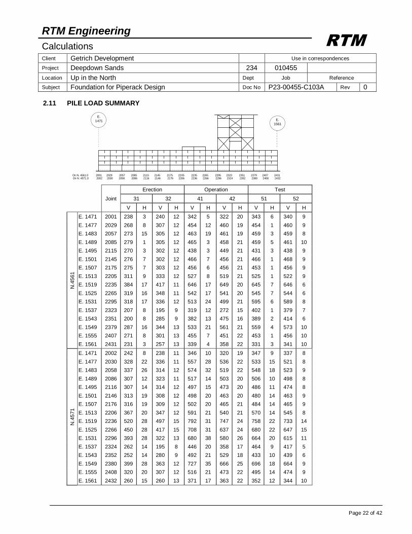
2.11 PILE LOAD SUMMARY
Erection Operation Test
Joint 31 32 41 42 51 52
V H V H V H V H V H V H
N.4
561
E. 1471 2001 238 3 240 12 342 5 322 20 343 6 340 9
E. 1477 2029 268 8 307 12 454 12 460 19 454 1 460 9
E. 1483 2057 273 15 305 12 463 19 461 19 459 3 459 8
E. 1489 2085 279 1 305 12 465 3 458 21 459 5 461 10
E. 1495 2115 270 3 302 12 438 3 449 21 431 3 438 9
E. 1501 2145 276 7 302 12 466 7 456 21 466 1 468 9
E. 1507 2175 275 7 303 12 456 6 456 21 453 1 456 9
E. 1513 2205 311 9 333 12 527 8 519 21 525 1 522 9
E. 1519 2235 384 17 417 11 646 17 649 20 645 7 646 6
E. 1525 2265 319 16 348 11 542 17 541 20 545 7 544 6
E. 1531 2295 318 17 336 12 513 24 499 21 595 6 589 8
E. 1537 2323 207 8 195 9 319 12 272 15 402 1 379 7
E. 1543 2351 200 8 285 9 382 13 475 16 389 2 414 6
E. 1549 2379 287 16 344 13 533 21 561 21 559 4 573 10
E. 1555 2407 271 8 301 13 455 7 451 22 453 1 456 10
E. 1561 2431 231 3 257 13 339 4 358 22 331 3 341 10
N.4
571
E. 1471 2002 242 8 238 11 346 10 320 19 347 9 337 8
E. 1477 2030 328 22 336 11 557 28 536 22 533 15 521 8
E. 1483 2058 337 26 314 12 574 32 519 22 548 18 523 9
E. 1489 2086 307 12 323 11 517 14 503 20 506 10 498 8
E. 1495 2116 307 14 314 12 497 15 473 20 486 11 474 8
E. 1501 2146 313 19 308 12 498 20 463 20 480 14 463 9
E. 1507 2176 316 19 309 12 502 20 465 21 484 14 465 9
E. 1513 2206 367 20 347 12 591 21 540 21 570 14 545 8
E. 1519 2236 520 28 497 15 792 31 747 24 758 22 733 14
E. 1525 2266 450 28 417 15 708 31 637 24 680 22 647 15
E. 1531 2296 393 28 322 13 680 38 580 26 664 20 615 11
E. 1537 2324 262 14 195 8 446 20 358 17 464 9 417 5
E. 1543 2352 252 14 280 9 492 21 529 18 433 10 439 6
E. 1549 2380 399 28 363 12 727 35 666 25 696 18 664 9
E. 1555 2408 320 20 307 12 516 21 473 22 495 14 474 9
E. 1561 2432 260 15 260 13 371 17 363 22 352 12 344 10
On N. 4561.0 2001 2029 2057 2085 2115 2145 2175 2205 2235 2265 2295 2323 2351 2379 2407 2431 On N. 4571.0 2002 2030 2058 2086 2116 2146 2176 2206 2236 2266 2296 2324 2352 2380 2408 2432
E.
1471 E.
1561
RTM Engineering
Calculations Client Getrich Development Use in correspondences
Project Deepdown Sands 234 010455
Location Up in the North Dept Job Reference
Subject Foundation for Piperack Design Doc No P23-00455-C103A Rev 0
Page 23 of 42
RTM
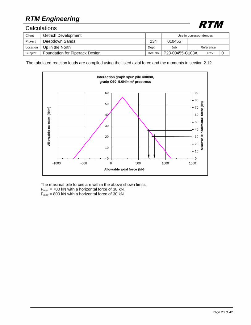
The tabulated reaction loads are compiled using the listed axial force and the moments in section 2.12.
Interaction graph spun pile 400/80,
grade C60 5.0N/mm² prestress
0
10
20
30
40
50
60
-1000 -500 0 500 1000 1500
Allowable axial force (kN)
All
ow
able
mo
men
t (k
Nm
)
0
10
20
30
40
50
60
70
80
90
All
ow
able
ho
rizo
nta
l fo
rce
(kN
)
The maximal pile forces are within the above shown limits. Fmax = 700 kN with a horizontal force of 38 kN. Fmax = 800 kN with a horizontal force of 30 kN.
RTM Engineering
Calculations Client Getrich Development Use in correspondences
Project Deepdown Sands 234 010455
Location Up in the North Dept Job Reference
Subject Foundation for Piperack Design Doc No P23-00455-C103A Rev 0
Page 24 of 42
RTM
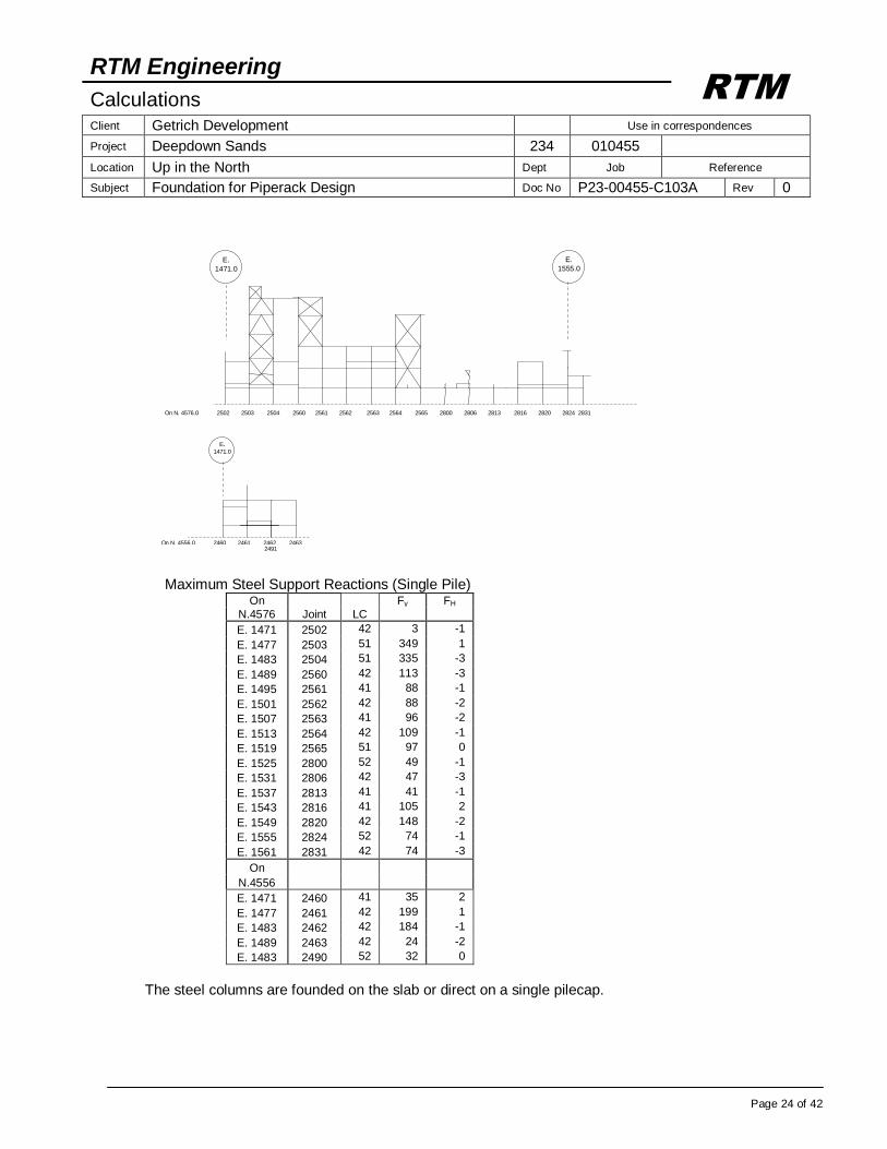
Maximum Steel Support Reactions (Single Pile)
On Fy FH
N.4576 Joint LC
E. 1471 2502 42 3 -1
E. 1477 2503 51 349 1
E. 1483 2504 51 335 -3
E. 1489 2560 42 113 -3
E. 1495 2561 41 88 -1
E. 1501 2562 42 88 -2
E. 1507 2563 41 96 -2
E. 1513 2564 42 109 -1
E. 1519 2565 51 97 0
E. 1525 2800 52 49 -1
E. 1531 2806 42 47 -3
E. 1537 2813 41 41 -1
E. 1543 2816 41 105 2
E. 1549 2820 42 148 -2
E. 1555 2824 52 74 -1
E. 1561 2831 42 74 -3
On
N.4556
E. 1471 2460 41 35 2
E. 1477 2461 42 199 1
E. 1483 2462 42 184 -1
E. 1489 2463 42 24 -2
E. 1483 2490 52 32 0
The steel columns are founded on the slab or direct on a single pilecap.
E.
1471.0
E.
1555.0
On N. 4576.0 2502 2503 2504 2560 2561 2562 2563 2564 2565 2800 2806 2813 2816 2820 2824 2831
E. 1471.0
On N. 4556.0 2460 2461 2462 2463
2491
RTM Engineering
Calculations Client Getrich Development Use in correspondences
Project Deepdown Sands 234 010455
Location Up in the North Dept Job Reference
Subject Foundation for Piperack Design Doc No P23-00455-C103A Rev 0
Page 25 of 42
RTM
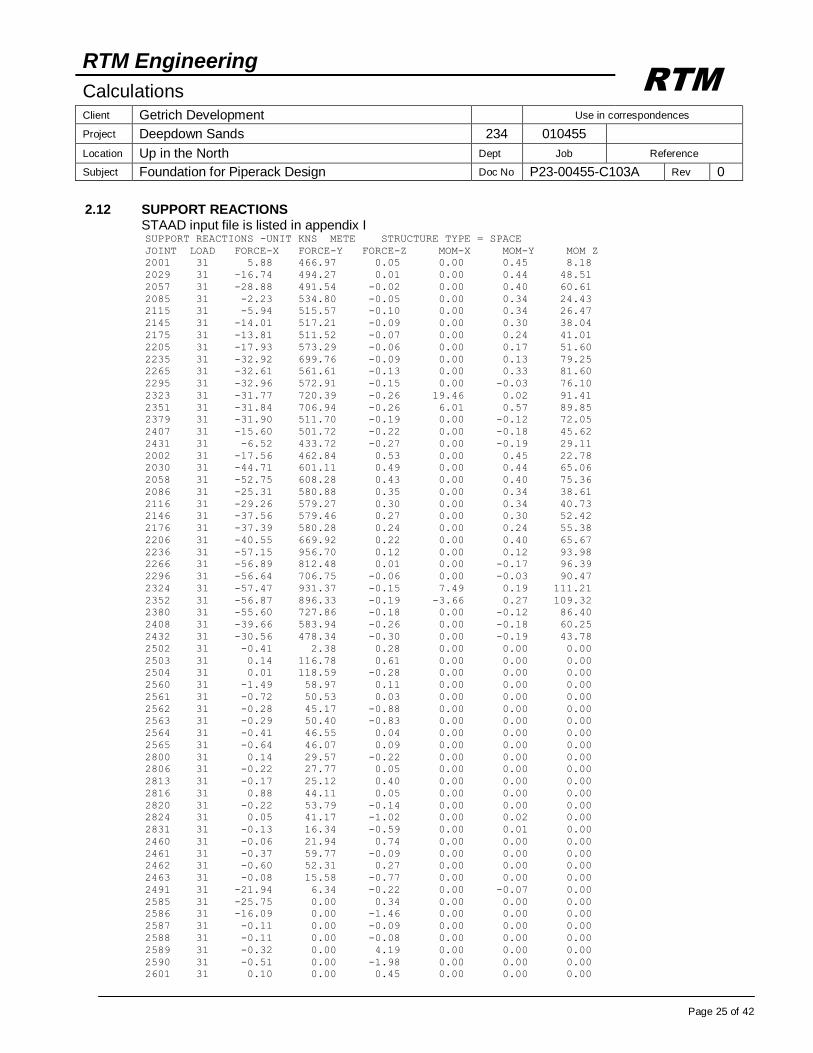
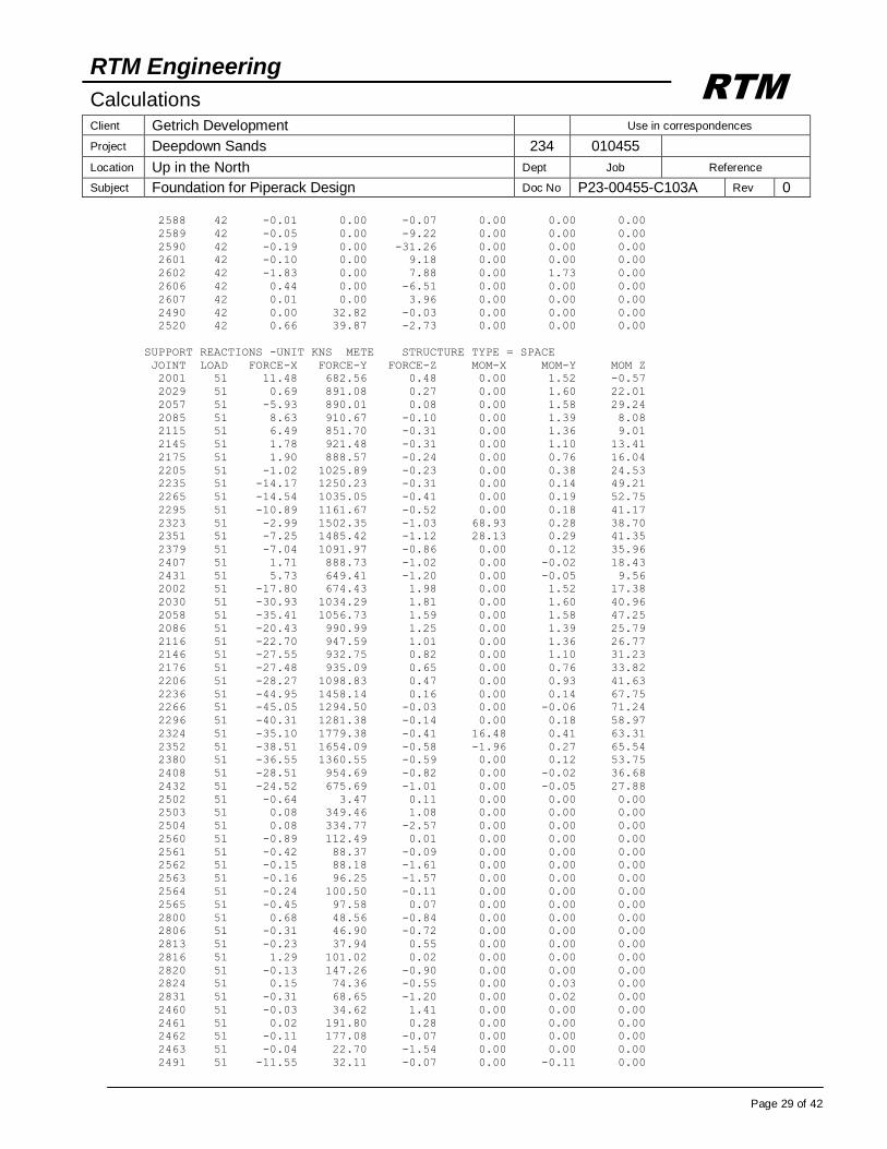
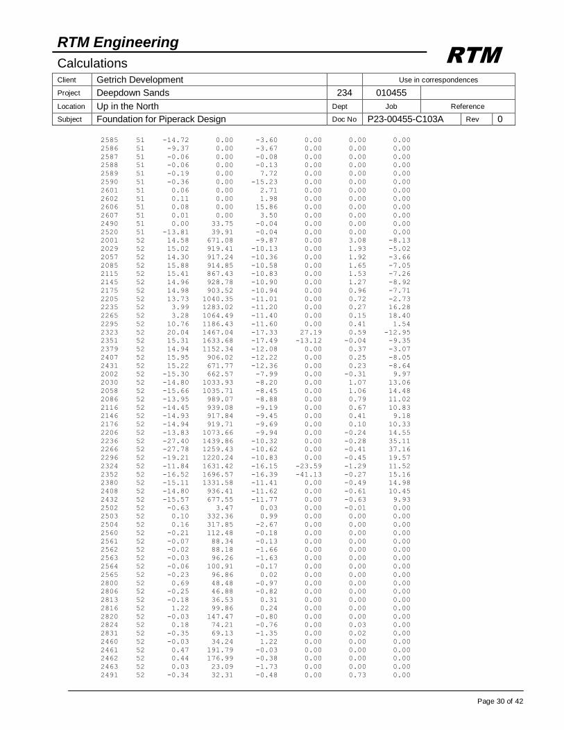
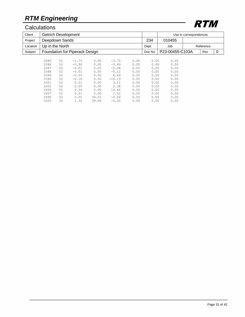
2.12 SUPPORT REACTIONS STAAD input file is listed in appendix I
SUPPORT REACTIONS -UNIT KNS METE STRUCTURE TYPE = SPACE
JOINT LOAD FORCE-X FORCE-Y FORCE-Z MOM-X MOM-Y MOM Z
2001 31 5.88 466.97 0.05 0.00 0.45 8.18
2029 31 -16.74 494.27 0.01 0.00 0.44 48.51
2057 31 -28.88 491.54 -0.02 0.00 0.40 60.61
2085 31 -2.23 534.80 -0.05 0.00 0.34 24.43
2115 31 -5.94 515.57 -0.10 0.00 0.34 26.47
2145 31 -14.01 517.21 -0.09 0.00 0.30 38.04
2175 31 -13.81 511.52 -0.07 0.00 0.24 41.01
2205 31 -17.93 573.29 -0.06 0.00 0.17 51.60
2235 31 -32.92 699.76 -0.09 0.00 0.13 79.25
2265 31 -32.61 561.61 -0.13 0.00 0.33 81.60
2295 31 -32.96 572.91 -0.15 0.00 -0.03 76.10
2323 31 -31.77 720.39 -0.26 19.46 0.02 91.41
2351 31 -31.84 706.94 -0.26 6.01 0.57 89.85
2379 31 -31.90 511.70 -0.19 0.00 -0.12 72.05
2407 31 -15.60 501.72 -0.22 0.00 -0.18 45.62
2431 31 -6.52 433.72 -0.27 0.00 -0.19 29.11
2002 31 -17.56 462.84 0.53 0.00 0.45 22.78
2030 31 -44.71 601.11 0.49 0.00 0.44 65.06
2058 31 -52.75 608.28 0.43 0.00 0.40 75.36
2086 31 -25.31 580.88 0.35 0.00 0.34 38.61
2116 31 -29.26 579.27 0.30 0.00 0.34 40.73
2146 31 -37.56 579.46 0.27 0.00 0.30 52.42
2176 31 -37.39 580.28 0.24 0.00 0.24 55.38
2206 31 -40.55 669.92 0.22 0.00 0.40 65.67
2236 31 -57.15 956.70 0.12 0.00 0.12 93.98
2266 31 -56.89 812.48 0.01 0.00 -0.17 96.39
2296 31 -56.64 706.75 -0.06 0.00 -0.03 90.47
2324 31 -57.47 931.37 -0.15 7.49 0.19 111.21
2352 31 -56.87 896.33 -0.19 -3.66 0.27 109.32
2380 31 -55.60 727.86 -0.18 0.00 -0.12 86.40
2408 31 -39.66 583.94 -0.26 0.00 -0.18 60.25
2432 31 -30.56 478.34 -0.30 0.00 -0.19 43.78
2502 31 -0.41 2.38 0.28 0.00 0.00 0.00
2503 31 0.14 116.78 0.61 0.00 0.00 0.00
2504 31 0.01 118.59 -0.28 0.00 0.00 0.00
2560 31 -1.49 58.97 0.11 0.00 0.00 0.00
2561 31 -0.72 50.53 0.03 0.00 0.00 0.00
2562 31 -0.28 45.17 -0.88 0.00 0.00 0.00
2563 31 -0.29 50.40 -0.83 0.00 0.00 0.00
2564 31 -0.41 46.55 0.04 0.00 0.00 0.00
2565 31 -0.64 46.07 0.09 0.00 0.00 0.00
2800 31 0.14 29.57 -0.22 0.00 0.00 0.00
2806 31 -0.22 27.77 0.05 0.00 0.00 0.00
2813 31 -0.17 25.12 0.40 0.00 0.00 0.00
2816 31 0.88 44.11 0.05 0.00 0.00 0.00
2820 31 -0.22 53.79 -0.14 0.00 0.00 0.00
2824 31 0.05 41.17 -1.02 0.00 0.02 0.00
2831 31 -0.13 16.34 -0.59 0.00 0.01 0.00
2460 31 -0.06 21.94 0.74 0.00 0.00 0.00
2461 31 -0.37 59.77 -0.09 0.00 0.00 0.00
2462 31 -0.60 52.31 0.27 0.00 0.00 0.00
2463 31 -0.08 15.58 -0.77 0.00 0.00 0.00
2491 31 -21.94 6.34 -0.22 0.00 -0.07 0.00
2585 31 -25.75 0.00 0.34 0.00 0.00 0.00
2586 31 -16.09 0.00 -1.46 0.00 0.00 0.00
2587 31 -0.11 0.00 -0.09 0.00 0.00 0.00
2588 31 -0.11 0.00 -0.08 0.00 0.00 0.00
2589 31 -0.32 0.00 4.19 0.00 0.00 0.00
2590 31 -0.51 0.00 -1.98 0.00 0.00 0.00
2601 31 0.10 0.00 0.45 0.00 0.00 0.00

RTM Engineering
Calculations Client Getrich Development Use in correspondences
Project Deepdown Sands 234 010455
Location Up in the North Dept Job Reference
Subject Foundation for Piperack Design Doc No P23-00455-C103A Rev 0
Page 26 of 42
RTM
2602 31 0.15 0.00 0.39 0.00 0.00 0.00
2606 31 -0.16 0.00 -0.93 0.00 0.00 0.00
2607 31 0.02 0.00 1.04 0.00 0.00 0.00
2490 31 0.00 7.59 -0.01 0.00 0.00 0.00
2520 31 -29.42 26.79 0.59 0.00 0.00 0.00
2001 32 12.05 473.64 -20.54 0.00 3.95 -6.90
2029 32 11.94 611.14 -20.72 0.00 1.50 -5.41
2057 32 11.50 606.11 -20.88 0.00 1.49 -5.31
2085 32 12.29 604.50 -21.03 0.00 1.24 -5.87
2115 32 12.03 599.13 -21.18 0.00 1.05 -6.07
2145 32 12.34 599.16 -21.33 0.00 0.94 -6.84
2175 32 12.35 601.17 -21.49 0.00 0.88 -6.52
2205 32 11.61 662.23 -21.68 0.00 1.01 -2.98
2235 32 3.38 825.33 -21.91 0.00 0.49 13.20
2265 32 3.05 680.42 -22.16 0.00 0.34 13.08
2295 32 10.24 678.13 -22.39 0.00 0.57 -3.03
2323 32 14.43 709.71 -33.02 -52.26 0.80 -12.05
2351 32 13.26 1073.45 -33.16 -71.09 0.08 -11.65
2379 32 12.08 687.62 -22.74 0.00 0.54 -6.03
2407 32 12.87 596.31 -22.77 0.00 0.52 -7.34
2431 32 12.47 507.48 -22.77 0.00 0.52 -7.28
2002 32 -12.61 467.84 -19.09 0.00 -2.83 8.02
2030 32 -12.42 667.38 -19.24 0.00 -0.22 9.40
2058 32 -13.33 618.69 -19.40 0.00 -0.23 9.70
2086 32 -12.33 638.92 -19.70 0.00 -0.48 9.06
2116 32 -12.63 621.56 -19.95 0.00 -0.67 8.86
2146 32 -12.31 609.77 -20.17 0.00 -0.78 8.09
2176 32 -12.32 609.66 -20.38 0.00 -0.84 8.37
2206 32 -11.72 680.66 -20.59 0.00 -1.77 11.48
2236 32 -22.05 972.18 -20.86 0.00 -0.63 28.51
2266 32 -22.33 809.43 -21.20 0.00 -0.77 28.41
2296 32 -14.52 639.64 -21.48 0.00 -1.14 11.81
2324 32 -10.92 699.15 -31.70 -71.17 -3.04 7.55
2352 32 -12.93 1046.59 -31.88 -81.69 -0.67 8.47
2380 32 -12.70 725.33 -21.90 0.00 -1.18 8.83
2408 32 -12.24 607.40 -21.95 0.00 -1.20 7.80
2432 32 -12.66 511.33 -21.97 0.00 -1.20 7.90
2502 32 -0.41 2.38 0.13 0.00 -0.02 0.00
2503 32 0.22 82.68 0.43 0.00 0.00 0.00
2504 32 0.19 84.89 -0.48 0.00 0.00 0.00
2560 32 -0.12 58.95 -0.27 0.00 0.00 0.00
2561 32 -0.01 50.46 -0.04 0.00 0.00 0.00
2562 32 -0.02 45.17 -0.98 0.00 0.00 0.00
2563 32 -0.02 50.42 -0.94 0.00 0.00 0.00
2564 32 -0.04 47.43 -0.06 0.00 0.00 0.00
2565 32 -0.19 44.67 -0.03 0.00 0.00 0.00
2800 32 0.15 29.41 -0.47 0.00 0.00 0.00
2806 32 -0.13 27.72 -0.14 0.00 0.00 0.00
2813 32 -0.06 22.49 -0.08 0.00 0.00 0.00
2816 32 0.79 42.01 0.48 0.00 0.00 0.00
2820 32 -0.03 54.21 0.06 0.00 0.00 0.00
2824 32 0.10 40.88 -1.44 0.00 0.02 0.00
2831 32 -0.19 17.30 -0.88 0.00 0.01 0.00
2460 32 -0.06 21.18 0.38 0.00 0.00 0.00
2461 32 0.54 59.97 -0.72 0.00 0.00 0.00
2462 32 0.55 52.34 -0.35 0.00 0.00 0.00
2463 32 0.07 16.36 -1.15 0.00 0.00 0.00
2491 32 0.38 6.62 -1.04 0.00 1.60 0.00
2585 32 0.21 0.00 0.04 0.00 0.00 0.00
2586 32 0.61 0.00 -1.51 0.00 0.00 0.00
2587 32 -0.01 0.00 -0.08 0.00 0.00 0.00
2588 32 -0.01 0.00 -0.07 0.00 0.00 0.00
2589 32 -0.04 0.00 2.15 0.00 0.00 0.00
2590 32 -0.15 0.00 -3.88 0.00 0.00 0.00
2601 32 0.01 0.00 1.25 0.00 0.00 0.00

RTM Engineering
Calculations Client Getrich Development Use in correspondences
Project Deepdown Sands 234 010455
Location Up in the North Dept Job Reference
Subject Foundation for Piperack Design Doc No P23-00455-C103A Rev 0
Page 27 of 42
RTM
2602 32 0.04 0.00 1.19 0.00 0.00 0.00
2606 32 0.40 0.00 -3.73 0.00 0.00 0.00
2607 32 0.01 0.00 1.08 0.00 0.00 0.00
2490 32 0.00 8.00 -0.01 0.00 0.00 0.00
2520 32 0.92 26.80 0.26 0.00 0.00 0.00
SUPPORT REACTIONS -UNIT KNS METE STRUCTURE TYPE = SPACE
JOINT LOAD FORCE-X FORCE-Y FORCE-Z MOM-X MOM-Y MOM Z
2001 41 8.66 673.46 -4.64 0.00 2.37 9.03
2029 41 -23.74 853.80 -4.87 0.00 2.46 64.52
2057 41 -36.18 858.20 -5.07 0.00 2.43 75.72
2085 41 0.17 904.61 -5.26 0.00 2.14 26.58
2115 41 -2.69 850.23 -5.48 0.00 2.05 25.73
2145 41 -11.39 901.09 -5.52 0.00 1.80 36.19
2175 41 -11.18 873.75 -5.50 0.00 1.50 39.86
2205 41 -15.79 1005.74 -5.52 0.00 1.08 51.91
2235 41 -32.31 1221.37 -5.65 0.00 1.00 83.10
2265 41 -32.39 997.66 -5.80 0.00 1.22 91.00
2295 41 -46.60 934.60 -5.94 0.00 1.01 108.66
2323 41 -49.19 1090.10 -8.91 41.81 1.20 142.54
2351 41 -52.03 1396.23 -8.95 -1.51 1.75 140.71
2379 41 -40.89 987.39 -6.18 0.00 0.78 95.81
2407 41 -12.58 866.41 -6.30 0.00 0.60 48.02
2431 41 -3.76 648.34 -6.46 0.00 0.56 28.27
2002 41 -20.00 663.98 -4.04 0.00 2.37 26.83
2030 41 -57.51 1043.05 -4.25 0.00 2.46 84.55
2058 41 -64.83 1066.54 -4.48 0.00 2.43 93.55
2086 41 -28.76 996.94 -4.87 0.00 2.14 44.23
2116 41 -31.21 955.03 -5.14 0.00 2.05 43.17
2146 41 -40.17 947.53 -5.36 0.00 1.80 53.73
2176 41 -40.01 949.99 -5.56 0.00 1.50 57.37
2206 41 -42.69 1116.14 -5.76 0.00 2.28 68.81
2236 41 -62.50 1494.97 -6.09 0.00 0.99 101.36
2266 41 -62.35 1315.15 -6.33 0.00 0.72 109.22
2296 41 -75.48 1253.86 -6.49 0.00 1.01 126.23
2324 41 -81.55 1601.85 -9.72 -14.83 2.07 167.31
2352 41 -82.82 1772.18 -9.90 -33.97 1.32 164.73
2380 41 -70.28 1364.49 -6.97 0.00 0.78 113.59
2408 41 -42.27 969.28 -7.17 0.00 0.60 66.03
2432 41 -33.46 695.62 -7.33 0.00 0.56 46.33
2502 41 -0.63 3.47 -1.15 0.00 -0.01 0.00
2503 41 1.04 342.80 -0.46 0.00 0.00 0.00
2504 41 0.81 327.43 -4.13 0.00 0.00 0.00
2560 41 -1.70 112.61 -2.11 0.00 0.00 0.00
2561 41 -0.76 88.07 -0.59 0.00 0.00 0.00
2562 41 -0.28 88.19 -2.31 0.00 0.00 0.00
2563 41 -0.29 96.41 -2.32 0.00 0.00 0.00
2564 41 -0.43 108.34 -0.78 0.00 0.00 0.00
2565 41 -0.69 89.81 -0.63 0.00 0.00 0.00
2800 41 0.67 47.74 -2.21 0.00 0.00 0.00
2806 41 -0.32 47.02 -2.32 0.00 0.00 0.00
2813 41 -0.27 38.74 -1.35 0.00 0.00 0.00
2816 41 1.68 103.28 -1.05 0.00 0.00 0.00
2820 41 -0.29 147.59 -2.43 0.00 0.00 0.00
2824 41 0.11 72.32 -3.66 0.00 0.04 0.00
2831 41 -0.25 72.40 -2.94 0.00 0.02 0.00
2460 41 -0.12 34.83 1.54 0.00 -0.01 0.00
2461 41 -0.27 198.95 0.40 0.00 0.00 0.00
2462 41 -0.51 183.93 0.09 0.00 0.00 0.00
2463 41 -0.07 22.83 -1.51 0.00 0.01 0.00
2491 41 -29.50 30.65 2.35 0.00 -1.75 0.00
2585 41 -29.49 0.00 -6.54 0.00 0.00 0.00
2586 41 -17.34 0.00 -4.08 0.00 0.00 0.00
2587 41 -0.11 0.00 0.01 0.00 0.00 0.00

RTM Engineering
Calculations Client Getrich Development Use in correspondences
Project Deepdown Sands 234 010455
Location Up in the North Dept Job Reference
Subject Foundation for Piperack Design Doc No P23-00455-C103A Rev 0
Page 28 of 42
RTM
2588 41 -0.11 0.00 -0.09 0.00 0.00 0.00
2589 41 -0.34 0.00 -6.02 0.00 0.00 0.00
2590 41 -0.54 0.00 -28.27 0.00 0.00 0.00
2601 41 -0.01 0.00 7.93 0.00 0.00 0.00
2602 41 -1.72 0.00 6.62 0.00 1.73 0.00
2606 41 -0.08 0.00 -2.55 0.00 0.00 0.00
2607 41 0.02 0.00 3.89 0.00 0.00 0.00
2490 41 0.00 32.30 -0.04 0.00 0.00 0.00
2520 41 -29.63 39.90 -2.24 0.00 0.00 0.00
2001 42 14.84 637.36 -37.55 0.00 8.33 -6.08
2029 42 5.02 912.27 -37.93 0.00 5.97 10.46
2057 42 4.19 912.19 -38.26 0.00 5.95 9.87
2085 42 14.79 911.82 -38.58 0.00 5.40 -3.75
2115 42 14.96 890.72 -38.90 0.00 5.04 -6.83
2145 42 14.96 907.37 -39.19 0.00 4.78 -8.24
2175 42 14.98 903.90 -39.47 0.00 4.59 -7.62
2205 42 13.70 1034.12 -39.81 0.00 4.58 -2.61
2235 42 4.01 1286.14 -40.25 0.00 4.04 17.47
2265 42 3.24 1057.39 -40.71 0.00 3.87 22.08
2295 42 -3.21 981.22 -41.14 0.00 4.15 29.21
2323 42 -2.82 947.04 -60.69 -86.98 3.41 38.83
2351 42 -7.17 1764.91 -60.94 -127.22 2.53 39.63
2379 42 2.86 1111.10 -41.79 0.00 3.90 18.07
2407 42 15.89 899.78 -41.87 0.00 3.78 -4.89
2431 42 15.24 706.82 -41.91 0.00 3.76 -8.13
2002 42 -15.04 626.55 -35.88 0.00 -3.99 12.04
2030 42 -25.05 1052.30 -36.19 0.00 -1.30 28.70
2058 42 -25.50 1015.12 -36.55 0.00 -1.32 28.00
2086 42 -15.68 995.67 -37.19 0.00 -1.86 14.65
2116 42 -14.90 937.13 -37.69 0.00 -2.22 11.30
2146 42 -14.92 917.57 -38.15 0.00 -2.48 9.86
2176 42 -14.94 919.12 -38.57 0.00 -2.68 10.41
2206 42 -13.81 1063.92 -39.00 0.00 -3.43 14.64
2236 42 -27.38 1466.87 -39.54 0.00 -2.62 36.30
2266 42 -27.82 1237.56 -40.12 0.00 -2.77 40.84
2296 42 -33.19 1128.45 -40.62 0.00 -3.11 47.24
2324 42 -34.72 1231.62 -59.99 -136.02 -4.32 63.30
2352 42 -39.04 1931.26 -60.40 -153.60 -1.62 64.24
2380 42 -27.61 1309.88 -41.53 0.00 -3.36 36.37
2408 42 -14.86 931.56 -41.68 0.00 -3.48 13.63
2432 42 -15.55 713.03 -41.73 0.00 -3.50 10.45
2502 42 -0.62 3.47 -1.40 0.00 -0.04 0.00
2503 42 1.08 308.72 -0.77 0.00 0.00 0.00
2504 42 0.95 293.46 -4.45 0.00 0.00 0.00
2560 42 -0.34 112.59 -2.71 0.00 0.00 0.00
2561 42 -0.04 87.98 -0.71 0.00 0.00 0.00
2562 42 -0.03 88.19 -2.48 0.00 0.00 0.00
2563 42 -0.03 96.44 -2.50 0.00 0.00 0.00
2564 42 -0.06 109.82 -0.94 0.00 0.00 0.00
2565 42 -0.24 87.67 -0.81 0.00 0.00 0.00
2800 42 0.68 47.49 -2.60 0.00 0.00 0.00
2806 42 -0.20 46.98 -2.61 0.00 0.00 0.00
2813 42 -0.14 35.58 -2.07 0.00 0.00 0.00
2816 42 1.60 100.95 -0.43 0.00 0.00 0.00
2820 42 -0.10 148.23 -2.15 0.00 0.00 0.00
2824 42 0.16 71.86 -4.31 0.00 0.03 0.00
2831 42 -0.31 73.86 -3.39 0.00 0.02 0.00
2460 42 -0.14 33.97 1.04 0.00 0.00 0.00
2461 42 0.62 198.94 -0.40 0.00 0.00 0.00
2462 42 0.60 183.75 -0.71 0.00 0.00 0.00
2463 42 0.10 23.69 -2.00 0.00 0.00 0.00
2491 42 -7.11 31.04 1.55 0.00 0.18 0.00
2585 42 -3.72 0.00 -7.05 0.00 0.00 0.00
2586 42 -0.02 0.00 -4.15 0.00 0.00 0.00
2587 42 -0.01 0.00 0.03 0.00 0.00 0.00
RTM Engineering
Calculations Client Getrich Development Use in correspondences
Project Deepdown Sands 234 010455
Location Up in the North Dept Job Reference
Subject Foundation for Piperack Design Doc No P23-00455-C103A Rev 0
Page 29 of 42
RTM
2588 42 -0.01 0.00 -0.07 0.00 0.00 0.00
2589 42 -0.05 0.00 -9.22 0.00 0.00 0.00
2590 42 -0.19 0.00 -31.26 0.00 0.00 0.00
2601 42 -0.10 0.00 9.18 0.00 0.00 0.00
2602 42 -1.83 0.00 7.88 0.00 1.73 0.00
2606 42 0.44 0.00 -6.51 0.00 0.00 0.00
2607 42 0.01 0.00 3.96 0.00 0.00 0.00
2490 42 0.00 32.82 -0.03 0.00 0.00 0.00
2520 42 0.66 39.87 -2.73 0.00 0.00 0.00
SUPPORT REACTIONS -UNIT KNS METE STRUCTURE TYPE = SPACE
JOINT LOAD FORCE-X FORCE-Y FORCE-Z MOM-X MOM-Y MOM Z
2001 51 11.48 682.56 0.48 0.00 1.52 -0.57
2029 51 0.69 891.08 0.27 0.00 1.60 22.01
2057 51 -5.93 890.01 0.08 0.00 1.58 29.24
2085 51 8.63 910.67 -0.10 0.00 1.39 8.08
2115 51 6.49 851.70 -0.31 0.00 1.36 9.01
2145 51 1.78 921.48 -0.31 0.00 1.10 13.41
2175 51 1.90 888.57 -0.24 0.00 0.76 16.04
2205 51 -1.02 1025.89 -0.23 0.00 0.38 24.53
2235 51 -14.17 1250.23 -0.31 0.00 0.14 49.21
2265 51 -14.54 1035.05 -0.41 0.00 0.19 52.75
2295 51 -10.89 1161.67 -0.52 0.00 0.18 41.17
2323 51 -2.99 1502.35 -1.03 68.93 0.28 38.70
2351 51 -7.25 1485.42 -1.12 28.13 0.29 41.35
2379 51 -7.04 1091.97 -0.86 0.00 0.12 35.96
2407 51 1.71 888.73 -1.02 0.00 -0.02 18.43
2431 51 5.73 649.41 -1.20 0.00 -0.05 9.56
2002 51 -17.80 674.43 1.98 0.00 1.52 17.38
2030 51 -30.93 1034.29 1.81 0.00 1.60 40.96
2058 51 -35.41 1056.73 1.59 0.00 1.58 47.25
2086 51 -20.43 990.99 1.25 0.00 1.39 25.79
2116 51 -22.70 947.59 1.01 0.00 1.36 26.77
2146 51 -27.55 932.75 0.82 0.00 1.10 31.23
2176 51 -27.48 935.09 0.65 0.00 0.76 33.82
2206 51 -28.27 1098.83 0.47 0.00 0.93 41.63
2236 51 -44.95 1458.14 0.16 0.00 0.14 67.75
2266 51 -45.05 1294.50 -0.03 0.00 -0.06 71.24
2296 51 -40.31 1281.38 -0.14 0.00 0.18 58.97
2324 51 -35.10 1779.38 -0.41 16.48 0.41 63.31
2352 51 -38.51 1654.09 -0.58 -1.96 0.27 65.54
2380 51 -36.55 1360.55 -0.59 0.00 0.12 53.75
2408 51 -28.51 954.69 -0.82 0.00 -0.02 36.68
2432 51 -24.52 675.69 -1.01 0.00 -0.05 27.88
2502 51 -0.64 3.47 0.11 0.00 0.00 0.00
2503 51 0.08 349.46 1.08 0.00 0.00 0.00
2504 51 0.08 334.77 -2.57 0.00 0.00 0.00
2560 51 -0.89 112.49 0.01 0.00 0.00 0.00
2561 51 -0.42 88.37 -0.09 0.00 0.00 0.00
2562 51 -0.15 88.18 -1.61 0.00 0.00 0.00
2563 51 -0.16 96.25 -1.57 0.00 0.00 0.00
2564 51 -0.24 100.50 -0.11 0.00 0.00 0.00
2565 51 -0.45 97.58 0.07 0.00 0.00 0.00
2800 51 0.68 48.56 -0.84 0.00 0.00 0.00
2806 51 -0.31 46.90 -0.72 0.00 0.00 0.00
2813 51 -0.23 37.94 0.55 0.00 0.00 0.00
2816 51 1.29 101.02 0.02 0.00 0.00 0.00
2820 51 -0.13 147.26 -0.90 0.00 0.00 0.00
2824 51 0.15 74.36 -0.55 0.00 0.03 0.00
2831 51 -0.31 68.65 -1.20 0.00 0.02 0.00
2460 51 -0.03 34.62 1.41 0.00 0.00 0.00
2461 51 0.02 191.80 0.28 0.00 0.00 0.00
2462 51 -0.11 177.08 -0.07 0.00 0.00 0.00
2463 51 -0.04 22.70 -1.54 0.00 0.00 0.00
2491 51 -11.55 32.11 -0.07 0.00 -0.11 0.00
RTM Engineering
Calculations Client Getrich Development Use in correspondences
Project Deepdown Sands 234 010455
Location Up in the North Dept Job Reference
Subject Foundation for Piperack Design Doc No P23-00455-C103A Rev 0
Page 30 of 42
RTM
2585 51 -14.72 0.00 -3.60 0.00 0.00 0.00
2586 51 -9.37 0.00 -3.67 0.00 0.00 0.00
2587 51 -0.06 0.00 -0.08 0.00 0.00 0.00
2588 51 -0.06 0.00 -0.13 0.00 0.00 0.00
2589 51 -0.19 0.00 7.72 0.00 0.00 0.00
2590 51 -0.36 0.00 -15.23 0.00 0.00 0.00
2601 51 0.06 0.00 2.71 0.00 0.00 0.00
2602 51 0.11 0.00 1.98 0.00 0.00 0.00
2606 51 0.08 0.00 15.86 0.00 0.00 0.00
2607 51 0.01 0.00 3.50 0.00 0.00 0.00
2490 51 0.00 33.75 -0.04 0.00 0.00 0.00
2520 51 -13.81 39.91 -0.04 0.00 0.00 0.00
2001 52 14.58 671.08 -9.87 0.00 3.08 -8.13
2029 52 15.02 919.41 -10.13 0.00 1.93 -5.02
2057 52 14.30 917.24 -10.36 0.00 1.92 -3.66
2085 52 15.88 914.85 -10.58 0.00 1.65 -7.05
2115 52 15.41 867.43 -10.83 0.00 1.53 -7.26
2145 52 14.96 928.78 -10.90 0.00 1.27 -8.92
2175 52 14.98 903.52 -10.94 0.00 0.96 -7.71
2205 52 13.73 1040.35 -11.01 0.00 0.72 -2.73
2235 52 3.99 1283.02 -11.20 0.00 0.27 16.28
2265 52 3.28 1064.49 -11.40 0.00 0.15 18.40
2295 52 10.76 1186.43 -11.60 0.00 0.41 1.54
2323 52 20.04 1467.04 -17.33 27.19 0.59 -12.95
2351 52 15.31 1633.68 -17.49 -13.12 -0.04 -9.35
2379 52 14.94 1152.34 -12.08 0.00 0.37 -3.07
2407 52 15.95 906.02 -12.22 0.00 0.25 -8.05
2431 52 15.22 671.77 -12.36 0.00 0.23 -8.64
2002 52 -15.30 662.57 -7.99 0.00 -0.31 9.97
2030 52 -14.80 1033.93 -8.20 0.00 1.07 13.06
2058 52 -15.66 1035.71 -8.45 0.00 1.06 14.48
2086 52 -13.95 989.07 -8.88 0.00 0.79 11.02
2116 52 -14.45 939.08 -9.19 0.00 0.67 10.83
2146 52 -14.93 917.84 -9.45 0.00 0.41 9.18
2176 52 -14.94 919.71 -9.69 0.00 0.10 10.33
2206 52 -13.83 1073.66 -9.94 0.00 -0.24 14.55
2236 52 -27.40 1439.86 -10.32 0.00 -0.28 35.11
2266 52 -27.78 1259.43 -10.62 0.00 -0.41 37.16
2296 52 -19.21 1220.24 -10.83 0.00 -0.45 19.57
2324 52 -11.84 1631.42 -16.15 -23.59 -1.29 11.52
2352 52 -16.52 1696.57 -16.39 -41.13 -0.27 15.16
2380 52 -15.11 1331.58 -11.41 0.00 -0.49 14.98
2408 52 -14.80 936.41 -11.62 0.00 -0.61 10.45
2432 52 -15.57 677.55 -11.77 0.00 -0.63 9.93
2502 52 -0.63 3.47 0.03 0.00 -0.01 0.00
2503 52 0.10 332.36 0.99 0.00 0.00 0.00
2504 52 0.16 317.85 -2.67 0.00 0.00 0.00
2560 52 -0.21 112.48 -0.18 0.00 0.00 0.00
2561 52 -0.07 88.34 -0.13 0.00 0.00 0.00
2562 52 -0.02 88.18 -1.66 0.00 0.00 0.00
2563 52 -0.03 96.26 -1.63 0.00 0.00 0.00
2564 52 -0.06 100.91 -0.17 0.00 0.00 0.00
2565 52 -0.23 96.86 0.02 0.00 0.00 0.00
2800 52 0.69 48.48 -0.97 0.00 0.00 0.00
2806 52 -0.25 46.88 -0.82 0.00 0.00 0.00
2813 52 -0.18 36.53 0.31 0.00 0.00 0.00
2816 52 1.22 99.86 0.24 0.00 0.00 0.00
2820 52 -0.03 147.47 -0.80 0.00 0.00 0.00
2824 52 0.18 74.21 -0.76 0.00 0.03 0.00
2831 52 -0.35 69.13 -1.35 0.00 0.02 0.00
2460 52 -0.03 34.24 1.22 0.00 0.00 0.00
2461 52 0.47 191.79 -0.03 0.00 0.00 0.00
2462 52 0.44 176.99 -0.38 0.00 0.00 0.00
2463 52 0.03 23.09 -1.73 0.00 0.00 0.00
2491 52 -0.34 32.31 -0.48 0.00 0.73 0.00
RTM Engineering
Calculations Client Getrich Development Use in correspondences
Project Deepdown Sands 234 010455
Location Up in the North Dept Job Reference
Subject Foundation for Piperack Design Doc No P23-00455-C103A Rev 0
Page 31 of 42
RTM
2585 52 -1.73 0.00 -3.75 0.00 0.00 0.00
2586 52 -0.90 0.00 -3.69 0.00 0.00 0.00
2587 52 -0.01 0.00 -0.08 0.00 0.00 0.00
2588 52 -0.01 0.00 -0.12 0.00 0.00 0.00
2589 52 -0.05 0.00 6.69 0.00 0.00 0.00
2590 52 -0.18 0.00 -16.19 0.00 0.00 0.00
2601 52 0.01 0.00 3.11 0.00 0.00 0.00
2602 52 0.05 0.00 2.38 0.00 0.00 0.00
2606 52 0.34 0.00 14.46 0.00 0.00 0.00
2607 52 0.01 0.00 3.52 0.00 0.00 0.00
2490 52 0.00 34.01 -0.04 0.00 0.00 0.00
2520 52 1.32 39.90 -0.20 0.00 0.00 0.00
RTM Engineering
Calculations Client Getrich Development Use in correspondences
Project Deepdown Sands 234 010455
Location Up in the North Dept Job Reference
Subject Foundation for Piperack Design Doc No P23-00455-C103A Rev 0
Page 32 of 42
RTM
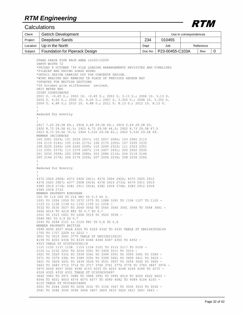
STAAD SPACE PIPE RACK AREA 10100/10200
INPUT WIDTH 72
*FRIDAY 8 OCTOBER '99 PILE LOADING ARRANGEMENTS REVISITED AND FINALISED
*PILECAP AND PAVING LOADS ADDED
*DETAIL DESIGN CARRIED OUT FOR CONCRETE DESIGN.
*WIND BRACING BAY REMAINS IN PLACE OF PREVIOUS ANCHOR BAY
*UPDATED FOR BRITISH SECTIONS
*26 October pile stiffnesses revised.
UNIT METER KNS
JOINT COORDINATES
2001 0. -0.65 0.; 2002 10. -0.65 0.; 2003 0. 3.13 0.; 2004 10. 3.13 0.
2005 0. 4.05 0.; 2006 10. 4.05 0.; 2007 0. 5.355 0.; 2008 10. 5.355 0.
2009 0. 6.88 0.; 2010 10. 6.88 0.; 2011 0. 8.13 0.; 2012 10. 8.13 0.
:
:
Reduced for brevity
:
:
2917 7.23 29.58 69.; 2918 2.49 29.58 69.; 2919 2.49 29.58 63.
2920 8.73 29.58 61.5; 2921 8.73 29.58 64.5; 2922 8.73 29.58 67.5
2923 8.73 29.58 70.5; 2924 5.535 29.58 63.; 2925 5.535 29.58 69.
MEMBER INCIDENCES
100 2001 2029; 101 2029 2057; 102 2057 2085; 103 2085 2115
104 2115 2145; 105 2145 2175; 106 2175 2205; 107 2205 2235
108 2235 2265; 109 2265 2295; 110 2295 2323; 111 2323 2351
112 2351 2379; 113 2379 2407; 114 2407 2431; 200 2002 2030
201 2030 2058; 202 2058 2086; 203 2086 2116; 204 2116 2146
205 2146 2176; 206 2176 2206; 207 2206 2236; 208 2236 2266
:
:
Reduced for Brevity
:
:
4372 2924 2904; 4373 2924 2911; 4374 2904 2925; 4375 2925 2912
4376 2925 2907; 4377 2908 2919; 4378 2919 2733; 4379 2911 2919
4380 2919 2718; 4381 2911 2918; 4382 2918 2748; 4383 2912 2918
4384 2918 2733
MEMBER PROPERTY EUROPEAN
100 TO 114 200 TO 214 PRI YD 0.3 ZD 3.
1001 TO 1056 1059 TO 1072 1075 TO 1088 1091 TO 1104 1107 TO 1120 -
1123 to 1136 1139 to 1152 1155 to 1224 -
3532 TO 3535 3537 TO 3540 3542 TO 3545 3560 3561 3566 TO 3568 3661 -
3662 4214 TO 4219 PRI YD 0.7 ZD 0.7
1501 TO 1515 1601 TO 1608 3519 TO 3525 3536 -
3546 PRI YD 0.9 ZD 0.7
2045 TO 2048 2121 to 2124 PRI YD 0.8 ZD 0.6
MEMBER PROPERTY BRITISH
3999 4000 4027 4028 4326 TO 4329 4332 TO 4335 TABLE ST UB610X305X149
1705 TO 1707 2209 to 2212 -
3501 TO 3515 3541 3775 TABLE ST UB533X210X101
4199 TO 4203 4336 TO 4339 4344 4346 4347 4350 TO 4352 -
4353 TABLE ST UC305X305X118
1121 1122 1137 1138 1153 1154 2101 TO 2115 2117 TO 2120 -
2125 to 2132 3201 TO 3224 3301 TO 3309 3311 TO 3319 -
3321 TO 3329 3331 TO 3339 3341 TO 3349 3351 TO 3359 3361 TO 3369 -
3371 TO 3379 3381 TO 3389 3391 TO 3399 3401 TO 3409 3411 TO 3419 -
3421 TO 3429 3431 TO 3439 3526 TO 3531 3557 TO 3559 3562 TO 3565 -
3663 TO 3683 3712 3714 TO 3717 3760 3761 3774 3776 TO 3783 3867 3974 -
3975 4056 4057 4092 4096 4153 4223 TO 4225 4248 4249 4266 TO 4272 -
4324 4325 4330 4331 TABLE ST UC305X305X97
3642 3965 TO 3971 3986 TO 3989 3991 TO 3995 4014 TO 4020 4022 4023 -
4044 TO 4051 4053 4074 4075 4077 TO 4080 4082 TO 4089 4104 4105 -
4125 TABLE ST UC254X254X89
2001 TO 2044 2049 TO 2056 3101 TO 3156 3547 TO 3550 3553 TO 3556 -
3581 TO 3586 3595 3596 3606 3607 3609 3610 3620 3621 3641 3643 -
RTM Engineering
Calculations Client Getrich Development Use in correspondences
Project Deepdown Sands 234 010455
Location Up in the North Dept Job Reference
Subject Foundation for Piperack Design Doc No P23-00455-C103A Rev 0
Page 33 of 42
RTM
3648 TO 3651 3684 TO 3690 3729 3730 3741 3742 3758 3759 3826 TO 3831 -
3838 TO 3840 3857 3858 3972 3973 3978 3979 3996 TO 3998 4003 4004 -
4008 4009 4012 4013 4024 TO 4026 4029 TO 4033 4037 4038 4054 4055 -
4134 4154 4171 4181 TO 4188 4191 TO 4198 4204 TO 4213 4220 TO 4222 -
4228 4231 TO 4236 4247 4250 TO 4255 4278 TO 4280 4283 TO 4287 4289 -
4290 4367 TABLE ST UC254X254X73
3569 TO 3571 3574 3577 TO 3580 3587 3589 TO 3591 3623 3644 TO 3647 -
3654 3655 3657 TO 3659 3724 3725 3784 TO 3801 3803 TO 3806 -
3843 TO 3846 3868 3980 3981 4064 4065 4076 4081 4132 4152 4155 4156 -
4160 TO 4163 4169 4172 4227 TABLE ST UC203X203X52
3624 TO 3632 TABLE ST UC203X203X60
3001 TO 3028 3551 3552 3710 3711 3713 3718 TO 3721 3726 TO 3728 3746 -
3747 3802 3808 TO 3815 3817 TO 3825 3976 3977 3982 TO 3985 4001 4002 -
4005 TO 4007 4010 4011 4034 TO 4036 4039 TO 4043 4058 TO 4063 -
4066 TO 4073 4151 4189 4229 4230 4237 TO 4246 4256 4257 4264 4265 -
4273 TO 4277 4281 4322 TABLE ST UC203X203X46
3633 3637 3652 3653 3656 3660 TABLE ST CH200X75X23
4090 4091 4093 TO 4095 4097 TO 4103 4124 4128 TO 4131 4133 4282 4288 -
4340 TO 4343 4345 4348 4349 4366 4368 TABLE ST UC203X203X46
3588 3691 TO 3709 3748 3749 4159 4258 TO 4263 4323 TABLE ST UC152X152X30
3722 3723 3743 3762 TO 3773 3832 TO 3837 3841 3842 3869 4157 4158 -
4164 TO 4168 4170 4190 4226 4291 TABLE ST UC152X152X23
4108 TO 4123 4135 TO 4150 TABLE ST UA120X120X10
3731 TO 3738 3847 TO 3854 3859 3861 TO 3863 TABLE ST UA100X100X8
3870 TO 3873 4173 TO 4180 4369 TO 4376 TABLE ST UA100X100X8
4106 4107 4126 4127 4377 TO 4384 TABLE ST UA100X100X8
4354 TO 4365 TABLE ST UA80X80X8
3750 TO 3757 TABLE ST UA80X80X8
MEMBER RELEASE
3001 TO 3028 3101 3102 3105 3106 3109 3110 3113 3114 3117 3118 3121 -
3122 3125 3126 3129 3130 3133 3134 3137 3138 3141 3142 3145 3146 3149 -
3150 3153 3154 3217 3218 3221 3222 3301 3304 3307 3311 3314 3317 3321 -
3324 3327 3331 3334 3337 3341 3344 3347 3351 3354 3357 3361 3364 3367 -
3371 3374 3377 3381 3384 3387 3391 3394 3397 3401 3404 3407 3411 3414 -
3417 3421 3424 3427 3431 3434 3437 3501 TO 3515 3541 -
3551 TO 3554 3581 3583 3585 TO 3587 3595 3609 3624 3627 3630 3642 -
3684 3688 3691 3692 3694 3696 3701 3702 3704 3710 3711 3713 3719 3720 -
3722 TO 3724 3726 3729 3733 3743 3746 3762 3763 3774 3775 3808 3810 -
3812 3814 3819 3821 TO 3830 3832 TO 3843 3857 3858 3867 3868 3968 -
3974 3976 3978 3986 3999 4001 4003 4007 4014 4019 4027 4029 4030 4032 -
4036 4044 4049 4056 4058 4060 4062 4063 4070 4073 4087 4088 -
4090 TO 4095 4097 TO 4102 4105 4128 TO 4134 4151 4154 4157 TO 4159 -
4161 4164 TO 4168 4170 4220 TO 4230 4242 4243 4250 4258 4261 4263 -
4265 4273 TO 4277 4279 4281 4282 4284 4285 4336 TO 4343 START MY MZ
2001 2003 2005 2007 2009 2011 2013 2015 2017 2019 2021 2023 2025 2027 -
2101 2102 2105 2106 2109 2110 3201 3202 3205 3206 3209 3210 3213 -
3214 START MY MZ
2002 2004 2006 2008 2010 2012 2014 2016 2018 2020 2022 2024 2026 2028 -
2103 2104 2107 2108 2111 2112 3203 3204 3207 3208 3211 3212 3215 -
3216 END MY MZ
2029 2031 2033 2035 2037 2039 -
2041 2043 2049 2051 2053 2055 2113 2114 2117 2118 -
2125 2126 2129 2130 3547 3549 3562 3563 START MY MZ
2030 2032 2034 2036 2038 2040 -
2042 2044 2050 2052 2054 2056 2115 2119 2120 -
2127 2128 2131 2132 3548 3564 3565 4096 4278 END MY MZ
*RELEASE REMOVED TO PREVENT INSTABILITY IN SOLUTION
*3827 3828 -
*RELEASE REMOVED TO PREVENT INSTABILITY IN SOLUTION
*3904
3001 TO 3023 3025 TO 3028 3103 3104 3107 3108 3111 3112 3115 3116 -
3119 3120 3123 3124 3127 3128 3131 3132 3135 3136 3139 3140 3143 3144 -
3147 3148 3151 3152 3155 3156 3219 3220 3301 3304 3307 3311 -
3314 3317 3321 3324 3327 3331 3334 3337 3341 3344 3347 3351 3354 3357 -
3361 3364 3367 3371 3374 3377 3381 3384 3387 3391 3394 3397 3401 3404 -
RTM Engineering
Calculations Client Getrich Development Use in correspondences
Project Deepdown Sands 234 010455
Location Up in the North Dept Job Reference
Subject Foundation for Piperack Design Doc No P23-00455-C103A Rev 0
Page 34 of 42
RTM
3407 3411 3414 3417 3421 3424 3427 3431 3434 3437 3501 TO 3515 -
3541 3551 3552 3555 3556 3582 3584 TO 3587 3621 3626 -
3629 3632 3642 3691 3693 3695 3696 3701 3703 3705 3710 3711 3713 3718 -
3719 3721 TO 3723 3726 3743 3746 3759 3761 3764 3765 3774 3775 3782 -
3788 3809 3811 3813 3815 3818 3820 TO 3826 3829 3831 TO 3835 -
3837 TO 3842 3857 3858 3869 3967 3971 3977 3979 3989 3995 4002 4004 -
4007 4018 4023 4029 4031 4033 4036 4048 4053 4057 4059 4061 TO 4063 -
4070 4073 4092 4094 4095 4097 TO 4103 4105 4124 4128 TO 4134 4151 -
4157 TO 4159 4164 TO 4168 4170 4171 4226 4228 4233 4235 4241 4248 -
4249 4252 4254 4259 4262 4265 4270 4273 TO 4277 4280 4283 4286 4327 -
4331 4335 4338 4340 4341 4345 4347 TO 4349 4351 4353 END MY MZ
4206 4237 START FZ MY MZ
3867 3868 4152 END FZ MY MZ
4068 4071 START MY MZ
4069 4072 END MY MZ
104 111 208 START MZ
201 END MZ
MEMBER TRUSS
3697 TO 3700 3706 TO 3709 3731 TO 3738 3750 TO 3757 3766 TO 3773 -
3847 TO 3854 3859 3861 TO 3863 3870 TO 3873 3980 TO 3985 4005 4006 -
4008 TO 4013 4034 4035 4037 TO 4043 4064 TO 4067 4106 TO 4123 4126 -
4127 4135 TO 4150 4173 TO 4180 4190 4291 4354 TO 4365 4369 TO 4384
CONSTANT
E STEEL MEMB -
1121 1122 1137 1138 1153 1154 1705 TO 1707 -
2001 TO 2044 2049 TO 2056 2101 TO 2115 2117 TO 2120 2125 to 2132 -
3001 TO 3028 3101 TO 3156 3201 TO 3224 3301 TO 3309 3311 TO 3319 -
3321 TO 3329 3331 TO 3339 3341 TO 3349 3351 TO 3359 3361 TO 3369 -
3371 TO 3379 3381 TO 3389 3391 TO 3399 3401 TO 3409 3411 TO 3419 -
3421 TO 3429 3431 TO 3439 3501 TO 3515 3541 3547 TO 3559 -
3562 TO 3565 3569 TO 3571 3574 3577 TO 3591 3595 3596 3606 3607 3609 -
3610 3620 3621 3623 TO 3633 3637 3641 TO 3660 3663 TO 3738 -
3741 TO 3743 3746 TO 3806 3808 TO 3815 3817 TO 3854 3857 TO 3859 -
3861 TO 3863 3867 TO 3873 3965 TO 3989 3991 TO 4020 4022 TO 4051 -
4053 TO 4213 4220 TO 4291 4322 TO 4384
DENSITY STEEL MEMB -
1121 1122 1137 1138 1153 1154 1705 TO 1707 -
2001 TO 2044 2049 TO 2056 2101 TO 2115 2117 TO 2120 2125 to 2132 -
3001 TO 3028 3101 TO 3156 3201 TO 3224 3301 TO 3309 3311 TO 3319 -
3321 TO 3329 3331 TO 3339 3341 TO 3349 3351 TO 3359 3361 TO 3369 -
3371 TO 3379 3381 TO 3389 3391 TO 3399 3401 TO 3409 3411 TO 3419 -
3421 TO 3429 3431 TO 3439 3501 TO 3515 3541 3547 TO 3559 -
3562 TO 3565 3569 TO 3571 3574 3577 TO 3591 3595 3596 3606 3607 3609 -
3610 3620 3621 3623 TO 3633 3637 3641 TO 3660 3663 TO 3738 -
3741 TO 3743 3746 TO 3806 3808 TO 3815 3817 TO 3854 3857 TO 3859 -
3861 TO 3863 3867 TO 3873 3965 TO 3989 3991 TO 4020 4022 TO 4051 -
4053 TO 4213 4220 TO 4291 4322 TO 4384
POISSON STEEL MEMB -
1121 1122 1137 1138 1153 1154 1705 TO 1707 -
2001 TO 2044 2049 TO 2056 2101 TO 2115 2117 TO 2120 2125 to 2132 -
3001 TO 3028 3101 TO 3156 3201 TO 3224 3301 TO 3309 3311 TO 3319 -
3321 TO 3329 3331 TO 3339 3341 TO 3349 3351 TO 3359 3361 TO 3369 -
3371 TO 3379 3381 TO 3389 3391 TO 3399 3401 TO 3409 3411 TO 3419 -
3421 TO 3429 3431 TO 3439 3501 TO 3515 3541 3547 TO 3559 -
3562 TO 3565 3569 TO 3571 3574 3577 TO 3591 3595 3596 3606 3607 3609 -
3610 3620 3621 3623 TO 3633 3637 3641 TO 3660 3663 TO 3738 -
3741 TO 3743 3746 TO 3806 3808 TO 3815 3817 TO 3854 3857 TO 3859 -
3861 TO 3863 3867 TO 3873 3965 TO 3989 3991 TO 4020 4022 TO 4051 -
4053 TO 4213 4220 TO 4291 4322 TO 4384
BETA 90. MEMB 3569 TO 3571 3574 3577 TO 3580 3588 3623 3644 TO 3647 -
3663 TO 3690 3714 TO 3717 3741 3742 3758 TO 3761 3776 TO 3801 -
3803 TO 3806 4153 4154 4160 4169 4181 TO 4188 4191 TO 4205
CONSTANT
E CONCRETE MEMB 100 TO 114 200 TO 214 1001 TO 1056 1059 TO 1072 -
1075 TO 1088 1091 TO 1104 1107 TO 1120 1123 to 1136 1139 to 1152 -
RTM Engineering
Calculations Client Getrich Development Use in correspondences
Project Deepdown Sands 234 010455
Location Up in the North Dept Job Reference
Subject Foundation for Piperack Design Doc No P23-00455-C103A Rev 0
Page 35 of 42
RTM
1155 to 1224 1501 TO 1515 1601 TO 1608 1705 TO 1707 2045 TO 2048 -
2121 to 2124 2209 TO 2212 3217 to 3224 3519 TO 3540 -
3542 TO 3546 3560 3561 3566 TO 3568 3661 3662 4214 TO 4219
DENSITY CONCRETE MEMB 100 TO 114 200 TO 214 1001 TO 1056 1059 TO 1072 -
1075 TO 1088 1091 TO 1104 1107 TO 1120 1123 to 1136 1139 to 1152 -
1155 to 1224 1501 TO 1515 1601 TO 1608 1705 TO 1707 2045 TO 2048 -
2121 to 2124 2209 TO 2212 3217 to 3224 3519 TO 3540 -
3542 TO 3546 3560 3561 3566 TO 3568 3661 3662 4214 TO 4219
POISSON CONCRETE MEMB 100 TO 114 200 TO 214 1001 TO 1056 1059 TO 1072 -
1075 TO 1088 1091 TO 1104 1107 TO 1120 1123 to 1136 1139 to 1152 -
1155 to 1224 1501 TO 1515 1601 TO 1608 1705 TO 1707 2045 TO 2048 -
2121 to 2124 2209 TO 2212 3217 to 3224 3519 TO 3540 -
3542 TO 3546 3560 3561 3566 TO 3568 3661 3662 4214 TO 4219
SUPPORT
*FROM SOILS REPORT FOR ZONE 1
2001 2029 2057 2085 2115 2145 2175 -
2205 2235 2265 2295 -
FIXED BUT MX kfz 18824 KFY 92778 KMZ 1619
2323 2351 fixed but kfy 139167 kfz 28179 kmx 2429 kmz 2429
2379 2407 2431 -
2002 2030 2058 2086 2116 2146 2176 -
2206 2236 2266 2296 -
FIXED BUT MX kfz 18824 KFY 92778 KMZ 1619
2324 2352 fixed but kfy 139167 kfz 28179 kmx 2429 kmz 2429
2380 2408 2432 -
FIXED BUT MX kfz 18824 KFY 92778 KMZ 1619
* STRUCTURE A
* STRUCTURES B AND C BASES
2502 TO 2504 2560 TO 2565 2800 2806 2813 2816 2820 2824 -
2831 FIXED BUT mx mz KFX 11765 KFY 59643. KFZ 11765
2460 TO 2463 2491 fixeD but mx mz KFX 11765 KFY 59643. KFZ 11765
* STRUCTURE B AT ELEVATION
2585 TO 2590 2601 2602 2606 2607 FIXED BUT FY MX MZ
2490 2520 PINNED
LOAD 1 SELF WEIGHT
SELFWEIGHT Y -1.
*PILECAP DL
JOINT LOAD
2001 2002 2029 2030 2057 2058 2085 2086 2115 2116 2145 2146 2175 2176 -
2205 2206 2235 2236 2265 2266 2295 2296 2379 2380 2407 2408 2431 2432 -
FY -25.
2323 2324 2351 2352 FY -75.
*LOAD CASE 2 PAVING DL DELETED DUE TO INCLUSION OF GROUND BEAM
LOAD 2 PAVING IMPOSED
MEMBER LOAD
100 TO 114 200 TO 214 UNI GY -30.
LOAD 3 PIPERACK LOADS
MEMBER LOAD
*ELEVATION +111.500
2101 TO 2115 2117 TO 2132 3201 TO 3224 3562 TO 3565 4096 UNI GY -2.5
*ELEVATION +108.250
3101 TO 3156 3553 TO 3556 UNI GY -2.5
*ELEVATION +105.750
2001 TO 2056 3547 TO 3549 4278 UNI GY -2.5
*ELEVATION +103.250
3001 TO 3028 3551 3552 4256 4257 UNI GY -2.5
*MAIN STEEL
1501 TO 1515 1601 TO 1608 3501 TO 3515 3519 TO 3525 3536 3541 -
3546 UNI GY -8.
*INTERMEDIATE STEEL
3301 3304 3307 3311 3314 3317 3321 3324 3327 3331 3334 3337 3341 3344 -
3347 3351 3354 3357 3361 3364 3367 3371 3374 3377 3381 3384 3387 3391 -
3394 3397 3401 3404 3407 3411 3414 3417 3421 3424 3427 3431 3434 3437 -
3526 3529 3557 UNI GY -4.
*STRUCTURE A
RTM Engineering
Calculations Client Getrich Development Use in correspondences
Project Deepdown Sands 234 010455
Location Up in the North Dept Job Reference
Subject Foundation for Piperack Design Doc No P23-00455-C103A Rev 0
Page 36 of 42
RTM
3581 TO 3586 UNI GY -2.
3587 3589 3590 3654 3659 UNI GY -2.5
*STRUCTURE B AND C
3710 3711 3713 3719 3821 TO 3831 3857 3858 3868 4206 TO 4213 4228 -
4237 TO 4241 4243 4246 4250 TO 4255 4260 4263 4281 UNI GY -2.5
3691 3701 3718 3774 3775 3808 TO 3815 3817 TO 3822 4159 4168 4224 -
4249 4268 4269 4279 4280 4284 4286 UNI GY -2.
*STRUCTURE D
LOAD 4 PIPERACK WALKWAY
MEMBER LOAD
1705 1707 UNI GY -12.
1706 UNI GY -24.
2209 TO 2212 UNI GY -5.
LOAD 5 ANCHORAGE LOADS
MEMBER LOAD
1501 TO 1515 1601 TO 1608 3501 TO 3515 3519 TO 3525 3536 3541 -
3546 UNI GZ 0.9
LOAD 6 AIRCOOLER LOADS
MEMBER LOAD
2209 2210 CON GY -130.
1706 1707 CON GY -146. 4.
1706 1707 CON GX 12. 4.
JOINT LOAD
2252 FY -276.
2251 FY -130.
2282 FY -146.
2252 2282 FX 12.
LOAD 7 PLATFORM LOADS
*SVP PLATFORM
MEMBER LOAD
4084 UNI GY -3.75
3972 3973 UNI GY -18.75
3996 TO 3998 4024 TO 4026 UNI GY -30.
4054 4055 UNI GY -20.25
4085 UNI GY -5.25
*STRUCTURE A
3624 TO 3626 3630 TO 3632 UNI GY -5.3
3627 TO 3629 UNI GY -10.6
*STRUCTURE B
3712 3867 UNI GY -12.5
3838 TO 3840 UNI GY -5.
3843 3846 UNI GY -10.
3725 3730 UNI GY -12.5
4152 4171 UNI GY -12.5 0. 3.
JOINT LOAD
2088 2500 FY -37.5
2501 FY -75.
*STRUCTURE C
MEMBER LOAD
4229 4230 4266 4275 UNI GY -3.
4273 4274 4277 UNI GY -6.
LOAD 8 STAIR LOADS
MEMBER LOAD
3968 CON GY -5.7 6.33
4125 CON GY -4.9 0.97
3968 CON GY -23.4 7.25
4125 CON GY -26.8 1.89
3969 CON GY -24.1 2.65
3987 CON GY -22.2 5.55
3970 CON GY -30. 2.9
3989 CON GY -13.6 1.75
JOINT LOAD
2753 2755 2758 2764 FY -10.
LOAD 9 PIPE LOADS OPERATION (VERTICAL)
*SV PLATFORM
RTM Engineering
Calculations Client Getrich Development Use in correspondences
Project Deepdown Sands 234 010455
Location Up in the North Dept Job Reference
Subject Foundation for Piperack Design Doc No P23-00455-C103A Rev 0
Page 37 of 42
RTM
JOINT LOAD
2729 FY -38.
2912 FY -82.
2911 FY -143.
2908 FY -48.
2913 FY -109.
2910 FY -24.
2909 FY -19.
2905 FY -36.
2923 FY -30.
MEMBER LOAD
4092 CON GY -55. 4.7
4056 CON GY -12. 3.84
4338 CON GY -109. 1.5
3996 CON GY -26. 2.02
4347 CON GY -28.
4026 CON GY -25.5 0.48
4054 CON GY -25.5 2.02
4105 4134 CON GY -28. 1.2
*STRUCTURE A
3642 CON GY -40. 1.8
3642 CON GY -37.5 4.1
3606 3620 CON GY -38. 0.7
*STRUCTURE B
3726 CON GY -88.
3673 CON GY -57.
3843 CON GY -7. 4.8
3774 CON GY -16.
3775 CON GY -36.
3720 CON GY -20. 1.2
3749 CON GY -12.
3724 CON GY -15.
JOINT LOAD
2514 FY -14.
2618 FY -21.
2537 FY -12.
*STRUCTURE C
2818 FY -25.
2868 FY -37.
2834 FY -36.
MEMBER LOAD
4189 CON GY -7.
4264 CON GY -3.
*STRUCTURE D
LOAD 10 PIPE LOADS OPERATION (HORIZONTAL Z)
JOINT LOAD
2729 FZ 1.
2912 FZ 25.
2911 FZ 22.
2908 FZ 15.
2913 FZ 16.
2910 FZ 23.
2909 FZ 4.
2905 FZ 3.
2923 FZ 8.
MEMBER LOAD
4092 CON GZ 9. 4.7
4056 CON GZ 4. 3.84
4056 CON GZ 2. 2.49
4338 CON GZ 6. 1.5
3996 CON GZ 3. 2.02
4347 CON GZ 6.
4026 CON GZ 7. 0.48
4054 CON GZ 7. 2.5
4105 4134 CON GZ 9. 1.2
RTM Engineering
Calculations Client Getrich Development Use in correspondences
Project Deepdown Sands 234 010455
Location Up in the North Dept Job Reference
Subject Foundation for Piperack Design Doc No P23-00455-C103A Rev 0
Page 38 of 42
RTM
*STRUCTURE A
3642 CON GZ 1. 1.8
3642 CON GZ 1. 4.1
3606 3620 CON GZ -2.5 0.7
*STRUCTURE B
3673 CON GZ 9.
3843 CON GZ 1. 4.8
3774 CON GZ 2.5
3775 CON GZ 11.5
3720 CON GZ 3.5 1.2
JOINT LOAD
2618 FZ 9.
2514 FZ 3.
*STRUCTURE C
2818 FZ 7.
2868 FZ 32.
*STRUCTURE D
LOAD 11 PIPE LOADS OPERATION (HORIZONTAL X)
JOINT LOAD
2729 FX 10.
2912 FX 11.
2911 FX 20.
2908 FX 12.
2913 FX 11.
2910 FX 14.
2909 FX 3.
2905 FX 6.
2923 FX 2.
MEMBER LOAD
4092 CON GX 5. 4.7
4056 CON GX 8. 3.84
4338 CON GX 2. 1.5
3996 CON GX 7. 2.02
4347 CON GX 1.
4026 CON GX 3. 0.48
4105 4134 CON GX 9. 1.2
*STRUCTURE A
3642 CON GX 3.9 1.8
3642 CON GX 3.7 4.1
3606 3620 CON GX 2.6 0.7
*STRUCTURE B
3673 CON GX 13.
3843 CON GX 2. 4.8
3774 CON GX 2.8
3775 CON GX 7.8
3720 CON GX 5.5 1.2
JOINT LOAD
2618 FX 5.
2514 FX 3.
*STRUCTURE C
2818 FX 2.
2868 FX 8.
LOAD 12 PIPE LOADS TEST
JOINT LOAD
2729 FY -92.
2912 FY -124.
2911 FY -182.
2908 FY -67.
2913 FY -146.
2910 FY -100.
2909 FY -46.
2905 FY -34.
2920 FY -100.
2923 FY -94.
MEMBER LOAD
RTM Engineering
Calculations Client Getrich Development Use in correspondences
Project Deepdown Sands 234 010455
Location Up in the North Dept Job Reference
Subject Foundation for Piperack Design Doc No P23-00455-C103A Rev 0
Page 39 of 42
RTM
4092 CON GY -184. 4.7
4056 CON GY -24. 3.84
4056 CON GY -69. 2.49
4338 CON GY -109. 1.5
3996 CON GY -94. 2.02
4347 CON GY -96.
4026 CON GY -48. 0.48
4054 CON GY -48. 2.02
4134 CON GY -47. 1.2
4105 CON GY -90. 1.2
*STRUCTURE A
3642 CON GY -31. 1.8
3642 CON GY -30. 4.1
3606 3620 CON GY -38. 0.7
*STRUCTURE B
3726 CON GY -88.
3673 CON GY -130.
3843 CON GY -7. 4.8
3774 CON GY -16.
3775 CON GY -36.
3720 CON GY -20. 1.2
3724 CON GY -15.
3749 CON GY -12.
JOINT LOAD
2618 FY -21.
2514 FY -14.
2537 FY -12.
*STRUCTURE C
2818 FY -25.
2868 FY -37.
2834 FY -36.
MEMBER LOAD
4189 CON GY -7.
4264 CON GY -3.
LOAD 13 UPLIFTING WATER PRESSURES
MEMBER LOAD
*VOLUME OF 6 M3 X 10 KN/M3 DISTRIBUTED OVER 6 M = 10 KN/M
100 TO 114 200 TO 214 UNI GY 10.
LOAD 21 NORTH/SOUTH WIND (X-DIRECTION)
JOINT LOAD
*AT PIPE LEVELS
2005 2009 2013 2033 2037 2041 2061 2065 2069 2089 2093 2097 2119 2123 -
2127 2149 2153 2157 2179 2183 2187 2209 2213 2217 2239 2243 2247 2269 -
2273 2277 2299 2303 2307 2327 2331 2335 2355 2359 2363 2383 2387 2391 -
2411 2415 2419 2435 2439 FX 4.4
2017 2021 2025 2045 2049 2053 2073 2077 2081 2103 2107 2111 2133 2167 -
2171 2193 2197 2201 2223 2227 2231 2253 2257 2261 2283 2287 2291 2311 -
2315 2319 2339 2343 2347 2367 2371 2375 2395 2399 2403 2423 2427 -
2445 FX 2.2
MEMBER LOAD
*COMBINED WINDWARD AND LEEWARD RC COLUMN LOADS
1001 1015 1029 1043 1059 1075 1091 1107 1123 1139 1155 1169 1183 1197 -
1211 3532 UNI GX 1.3 1.35
1003 1005 1007 1009 1011 1013 1017 1019 1021 1023 1025 1027 1031 1033 -
1035 1037 1039 1041 1045 1047 1049 1051 1053 1055 1061 1063 1065 1067 -
1069 1071 1077 1079 1081 1083 1085 1087 1093 1095 1097 1099 1101 1103 -
1109 1111 1113 1115 1117 1119 1121 1125 1127 1129 1131 1133 1135 1137 -
1141 1143 1145 1147 1149 1151 1153 1157 1159 1161 1163 1165 1167 1171 -
1173 1175 1177 1179 1181 1185 1187 1189 1191 1193 1195 1199 1201 1203 -
1205 1207 1209 1213 1215 1217 1219 1221 1223 3534 3537 3539 3542 3544 -
3560 3566 UNI GX 1.3
*COMBINED WINDWARD AND LEEWARD RC BEAM LOADS +105.750
2001 2002 2005 2006 2009 2010 2013 2014 2017 2018 2021 2022 2025 2026 -
2029 2030 2033 2034 2037 2038 2041 2042 2045 2046 2049 2050 2053 2054 -
3547 3548 UNI GX 1.3
RTM Engineering
Calculations Client Getrich Development Use in correspondences
Project Deepdown Sands 234 010455
Location Up in the North Dept Job Reference
Subject Foundation for Piperack Design Doc No P23-00455-C103A Rev 0
Page 40 of 42
RTM
*COMBINED WINDWARD AND LEEWARD RC BEAM LOADS +111.500
2101 2103 2105 2107 2109 2111 2113 2115 2117 2119 2121 2123 2125 2127 -
2129 2131 3201 3203 3205 3207 3209 3211 3215 3217 3219 3221 3223 3562 -
3564 UNI GX 1.3
*COMBINED WINDWARD AND LEEWARD STEEL BEAM LOADS +108.250
3101 3103 3105 3107 3109 3111 3113 3115 3117 3119 3121 3123 3125 3127 -
3129 3131 3133 3135 3137 3139 3141 3143 3145 3147 3149 3151 3153 3155 -
3553 3555 UNI GX 0.35
*COMBINED WINDWARD AND LEEWARD STEEL BEAM LOADS +103.250
3001 3003 3005 3007 3009 3011 3013 3015 3017 3019 3021 3023 3025 3027 -
3551 UNI GX 0.35
*COMBINED WINDWARD AND LEEWARD STEEL HANGER
3302 3305 3308 3312 3315 3318 3322 3325 3328 3345 3348 3352 3355 3358 -
3362 3365 3368 3372 3375 3378 3382 3385 3388 3392 3395 3398 3402 3405 -
3408 3412 3415 3418 3422 3425 3428 3432 3435 3438 3527 3530 -
3558 UNI GX 0.56
*AIRCOOLERS
JOINT LOAD
2251 FX 3.
2251 FY 2.7
2252 FY -2.7
2252 2282 FY -9.5
MEMBER LOAD
2209 CON GX 3.
2209 CON GY 2.7
2210 CON GY -2.7
1706 1707 CON GX 10.5
1706 1707 CON GY 9.5
*SV PLATFORM
JOINT LOAD
2309 2310 2337 2338 2365 2366 2393 2394 FX 7.1
2721 2737 2752 2762 FX 18.8
*STRUCTURE B
2539 2540 2543 2544 FX 14.
LOAD 22 EAST/WEST WIND (Z-DIRECTION)
*LOAD ON EACH FRAME DUE TO PIPE LAYER +104.500
JOINT LOAD
2005 2006 2033 2034 2061 2062 2089 2090 2119 2120 2149 2150 2179 2180 -
2209 2210 2239 2240 2269 2270 2299 2300 2327 2328 2355 2356 2383 2384 -
2411 2412 2436 FZ 0.82
2009 2010 2037 2038 2065 2066 2093 2094 2123 2124 2153 2154 2183 2184 -
2213 2214 2243 2244 2273 2274 2303 2304 2331 2332 2359 2360 2387 2388 -
2415 2416 2439 2440 FZ 0.57
2013 2014 2041 2042 2069 2070 2097 2098 2127 2128 2157 2158 2187 2188 -
2217 2218 2247 2248 2277 2278 2307 2308 2335 2336 2363 2364 2391 2392 -
2419 2420 2443 2444 FZ 0.82
MEMBER LOAD
*FIRST FRAME COLUMNS
1001 1002 UNI GZ 0.81 1.35
1003 TO 1014 3566 UNI GZ 0.81
*FIRST FRAME RC BEAMS
1501 1601 UNI GZ 1.1
*FIRST FRAME STEEL BEAM
3501 UNI GZ 0.37
*LEEWARD +110.250
1602 TO 1608 3519 TO 3522 3546 UNI GZ 0.66
3523 TO 3525 UNI GZ 0.22
3307 3317 3327 3337 3347 3357 3367 3387 3397 3407 3417 3427 3437 -
3557 UNI GZ 0.17
*LEEWARD +107.000
3502 TO 3515 3541 UNI GZ 0.22
3304 3314 3324 3334 3344 3354 3364 3374 3384 3394 3404 3414 3424 3434 -
3529 3581 TO 3586 UNI GZ 0.17
*LEEWARD +104.500
1502 TO 1515 3536 UNI GZ 0.17
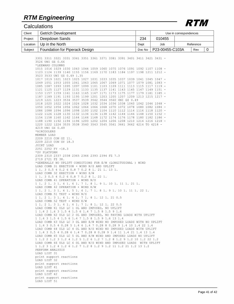
RTM Engineering
Calculations Client Getrich Development Use in correspondences
Project Deepdown Sands 234 010455
Location Up in the North Dept Job Reference
Subject Foundation for Piperack Design Doc No P23-00455-C103A Rev 0
Page 41 of 42
RTM
3301 3311 3321 3331 3341 3351 3361 3371 3381 3391 3401 3411 3421 3431 -
3526 UNI GZ 0.66
*LEEWARD COLUMNS
1015 1016 1029 1030 1043 1044 1059 1060 1075 1076 1091 1092 1107 1108 -
1123 1124 1139 1140 1155 1156 1169 1170 1183 1184 1197 1198 1211 1212 -
3523 3533 UNI GZ 0.49 1.35
1017 1019 1021 1023 1025 1027 1031 1033 1035 1037 1039 1041 1045 1047 -
1049 1051 1053 1055 1061 1063 1065 1067 1069 1071 1077 1079 1081 1083 -
1085 1087 1093 1095 1097 1099 1101 1103 1109 1111 1113 1115 1117 1119 -
1121 1125 1127 1129 1131 1133 1135 1137 1141 1143 1145 1147 1149 1151 -
1153 1157 1159 1161 1163 1165 1167 1171 1173 1175 1177 1179 1181 1185 -
1187 1189 1191 1193 1195 1199 1201 1203 1205 1207 1209 1213 1215 1217 -
1219 1221 1223 3534 3537 3539 3542 3544 3560 UNI GZ 0.49
1018 1020 1022 1024 1026 1028 1032 1034 1036 1038 1040 1042 1046 1048 -
1050 1052 1054 1056 1062 1064 1066 1068 1070 1072 1078 1080 1082 1084 -
1086 1088 1094 1096 1098 1100 1102 1104 1110 1112 1114 1116 1118 1120 -
1122 1126 1128 1130 1132 1134 1136 1138 1142 1144 1146 1148 1150 1152 -
1154 1158 1160 1162 1164 1166 1168 1172 1174 1176 1178 1180 1182 1186 -
1188 1190 1192 1194 1196 1200 1202 1204 1206 1208 1210 1214 1216 1218 -
1220 1222 1224 3535 3538 3540 3543 3545 3561 3661 3662 4214 TO 4218 -
4219 UNI GZ 0.49
*AIRCOOLERS
MEMBER LOAD
2209 2210 CON GZ 11.
2209 2210 CON GY 18.3
JOINT LOAD
2251 2252 FY -18.3
*SV PLATFORM
2309 2310 2337 2338 2365 2366 2393 2394 FZ 7.3
2719 2721 FZ 38.
*GENERALLY NO UPLIFT CONDITIONS FOR E/W (LONGITUDINAL ) WIND
LOAD COMB 31 ERECTION + WIND N/S AND UPLIFT
1 1. 3 0.5 4 0.2 6 0.8 7 0.2 8 1. 21 1. 13 1.
LOAD COMB 32 ERECTION + WIND E/W
1 1. 3 0.5 4 0.2 6 0.8 7 0.2 8 1. 22 1.
LOAD COMB 41 OPERATION + WIND N/S
1 1. 2 1. 3 1. 4 1. 6 1. 7 1. 8 1. 9 1. 10 1. 11 1. 21 1.
LOAD COMB 42 OPERATION + WIND E/W
1 1. 2 1. 3 1. 4 1. 5 1. 6 1. 7 1. 8 1. 9 1. 10 1. 11 1. 22 1.
LOAD COMB 51 TEST + WIND N/S
1 1. 2 1. 3 1. 4 1. 6 1. 7 1. 8 1. 12 1. 21 0.5
LOAD COMB 52 TEST + WIND E/W
1 1. 2 1. 3 1. 4 1. 6 1. 7 1. 8 1. 12 1. 22 0.5
LOAD COMB 61 ULS LC 1 DL AND IMPOSED, NO UPLIFT
1 1.4 2 1.6 3 1.5 4 1.5 6 1.4 7 1.5 8 1.5 9 1.6
LOAD COMB 62 ULS LC 2 DL AND IMPOSED, NO PAVING LOADS WITH UPLIFT
1 1.4 3 1.5 4 1.5 6 1.4 7 1.5 8 1.5 9 1.6 13 1.4
LOAD COMB 63 ULS LC 3 DL AND E/W WIND NO IMPOSED LOADS WITH NO UPLIFT
1 1.4 3 0.5 4 0.28 5 1.4 6 1.4 7 0.28 8 0.28 9 1.4 10 1.4 22 1.4
LOAD COMB 64 ULS LC 4 DL AND N/S WIND NO IMPOSED LOADS WITH UPLIFT
1 1.4 3 0.5 4 0.28 6 1.4 7 0.28 8 0.28 9 1.4 11 1.4 21 1.4 13 1.4
LOAD COMB 65 ULS LC 5 DL AND E/W WIND AND IMPOSED LOADS NO UPLIFT
1 1.2 2 1.2 3 1.2 4 1.2 5 1.2 6 1.2 7 1.2 8 1.2 9 1.2 10 1.2 22 1.2
LOAD COMB 66 ULS LC 6 DL AND N/S WIND AND IMPOSED LOADS WITH UPLIFT
1 1.2 3 1.2 4 1.2 6 1.2 7 1.2 8 1.2 9 1.2 11 1.2 21 1.2 13 1.2
PERFORM ANALYSIS
LOAD LIST 31
print support reactions
LOAD LIST 32
print support reactions
LOAD LIST 41
print support reactions
LOAD LIST 42
print support reactions
LOAD LIST 51
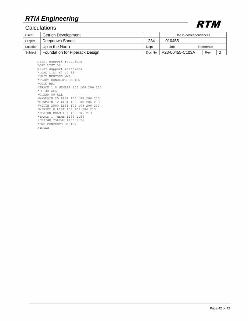
RTM Engineering
Calculations Client Getrich Development Use in correspondences
Project Deepdown Sands 234 010455
Location Up in the North Dept Job Reference
Subject Foundation for Piperack Design Doc No P23-00455-C103A Rev 0
Page 42 of 42
RTM
print support reactions
LOAD LIST 52
print support reactions
*LOAD LIST 61 TO 66
*UNIT NEWTONS MMS
*START CONCRETE DESIGN
*CODE BRI
*TRACK 1.0 MEMBER 106 108 206 213
*FC 40 ALL
*CLEAR 50 ALL
*MAXMAIN 20 LIST 106 108 206 213
*MINMAIN 12 LIST 106 108 206 213
*WIDTH 2500 LIST 106 108 206 213
*MINSEC 8 LIST 106 108 206 213
*DESIGN BEAM 106 108 206 213
*TRACK 1. MEMB 1155 1156
*DESIGN COLUMN 1155 1156
*END CONCRETE DESIGN
FINISH