Embed Size (px)
Citation preview

P^Reö^Sk SAOAC TECHNICAL LIBRARY
V 0712 01016804 4 DEVELOPMENT OF A DRAFT SPECIFICATION FOR TECHNICAL MANUAL QUALITY ASSURANCE
r>
C
by
Harold E. Price
TECHNICAL LIBRARY
December 1975
Prepared for
Naval Ship Research and Development Center
Bethesda, Maryland 20084
Contract W0167'76C-0012
BioTechnology, Inc. .3027 ROSEMARY LANE < FALLS CHURCH. VIRGINIA.


UNCLASSIFIED SECURITY CLASSIFICATION OF THIS PACE (Wh«* Dmim Bntmrmd)
REPORT DOCUMENTATION PAGE READ INSTRUCTIONS BEFORE COMPLETING FORM
1 REPORT NUMBER 2 OOVT ACCESSION NO 1 RECIPIENT'S CATALOG NUMBER
4 TITLE (and Subtitle)
Development of a Draft Specification for Technical Manual Quality Assurance
S. TVRE OF REPORT ft PERIOD COVERED
Final Report Oct 75 - Dec 75
ft. PERFORMING ORG. REPORT NUMBER
7 AUTHOR^«;
Harold E. Price
ft CONTRACT OR GRANT NUMBERf»;
N 00167-76-C-0012
9 PERFORMING ORGANIZATION NAME ANO ADDRESS
BioTechnology, Inc. 3027 Rosemary Lane Falls Church, Virginia
»0. PROGRAM ELEMENT. PROJECT, TASK AREA ft WORK UNIT NUMBERS
62757N F55522 WF 55-522-420 1-1860-011
II. CONTROLLING OFFICE NAME AND ADDRESS
David W. Taylor Naval Ship Research and Development Center, Operations Research Division, Bethesda, Maryland 20084
12. REPORT DATE
December 1975 13 NUMBER OF PAGES
_ao_ T« MONITORING AGENCY NAME ft ADORESSf// dlll»rmnl from Controlling Olllcm) IS. SECURITY CLASS, (ol thlm rmport)
UNCLASSIFIED IS«. DECLASSIFICATION/DOWNGRADING
SCHEDULE
«ft DISTRIBUTION STATEMENT (ot thl» Report,
Approved for Public Release: Distribution Unlimited
17 DISTRIBUTION STATEMENT (ol th» »b»tr»cl mntmrmd In Block 20, It dlttmrmnt from Rmport)
»ft. SUPPLEMENTARY NOTES
19 KEY WORDS (Continue on rmvmrmm »id» II nmcmmmmry mnd Identity by block nutnbmr)
Technical Manual, Quality Assurance, Validation, Verification, In-Process-Review, Presentation Techniques, Job Performance, Specification
20 ABSTRACT (Conllnu9 on rmvmr»m »Id» II n»c»»»mry mnd Idmnilty by block numb»r)
This report presents a Draft Specification for Technical Manual (TM) quality assurance (QA), to improve the clarity and content of TM's. The draft QA specification (1) maintains the concept and fundamental methods of technical manual quality assurance, that is, validation, verification, and in-process review, which have existed for some years; and (2) provides a systematic and structured way of reviewing technical manuals under development with respect to demonstrated or at least "concensus factors" for improving comprehension and content adequacy.
DD ,: FAT73 1473 EOITION OF 1 NOV 65 IS OBSOLETE
S/N 0102-014-6601 WCLASSIFTEn SECURITY CLASSIFICATION OF THIS PAGE (Whmn Dmtm Bntmrmd)

.LV-<iWlTY CLASSIFICATION OF THIS PAGtfWhfi Dmlm Bnfrmd)
SECURITY CLASSIFICATION OF THIS PAGErWh.n Dmtm Enfrmd)
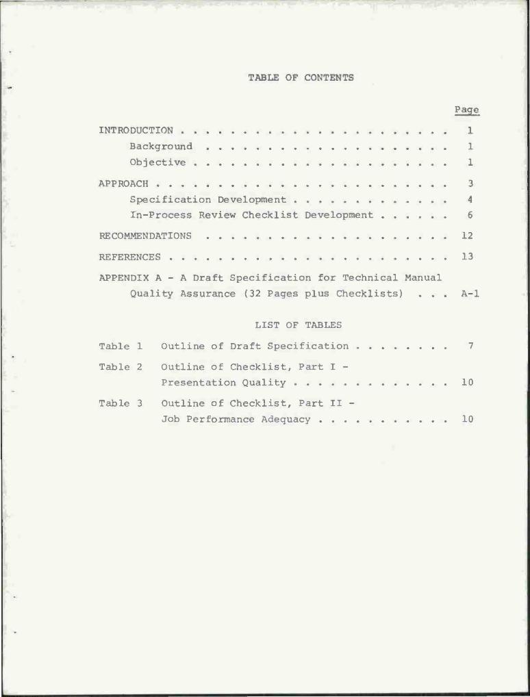
TABLE OF CONTENTS
Page
INTRODUCTION 1
Background 1
Objective 1
APPROACH 3
Specification Development 4
In-Process Review Checklist Development 6
RECOMMENDATIONS 12
REFERENCES 13
APPENDIX A - A Draft Specification for Technical Manual
Quality Assurance (32 Pages plus Checklists) . . . A-l
LIST OF TABLES
Table 1 Outline of Draft Specification 7
Table 2 Outline of Checklist, Part I -
Presentation Quality 10
Table 3 Outline of Checklist, Part II -
Job Performance Adequacy 10


INTRODUCTION
This effort was sponsored by the Navy Technical Manual System
(NTMS) Project Office located at the Naval Ship Research and Devel-
opment Center (NSRDC), Carderock, Maryland. The objective of NTMS
is to develop and operate an integrated Navy system for improving
technical manuals through:
• Standardized procedures and specifications.
• Better presentation methods.
• Obtaining and applying feedback.
• Responsive update procedures.
Background
Previous critiques of technical manuals have identified lack
of presentation clarity, problems in utilization on the job, and
technical inadequacies (including both scope and accuracy) as major
problem areas. All of these problem areas can be corrected or
certainly improved by better quality assurance procedures. Much
work needs to be done to assure that these problems are addressed
on a Navy-wide basis. As a starting point, a NAVMAT-level speci-
fication needs to be developed to permit project managers and
their contractors to establish and implement technical manual qual-
ity assurance procedures directed at alleviating these critical
problems.
Objective
The objective of this effort was to develop a draft specifi-
cation for technical manual quality assurance. The specification
should be developed to be used by NAVMAT in order to promulgate
policy regarding TM quality assurance and should treat both the
clarity and content of technical manuals. Specific requirements
are as follows:

1. Review (a) current specifications relating to TM pre-
paration; (b) other Navy policy guidance on maintenance
information and TM's; and (c) previous studies seeking
to improve TM quality.
2. Summarize relevant material useful in the preparation of
a TM quality assurance specification.
3. Prepare a draft specification intended to assure high
quality in Navy Technical Manuals. Incorporate a spe-
cific method for effectively performing in-process re-
views of TM preparation.
4. Prepare a report which outlines the rationale for the
particular approach taken, documents all relevant source
material, and summarizes any additional suggestions and
comments dealing with assurance of TM quality.
APPROACH
The philosophy of approach for this effort was basically one
of obtaining, reviewing, and synthesizing two sources of informa-
tion. The first source was current specifications and policy re-
lated to quality assurance and technical manual preparation. The
second source was recent new research directed toward simplifying
or improving technical manual comprehension and utilization. The
rationale for this philosophy of approach is also twofold. First,
there are several good quality assurance and/or TM preparation
specifications that have been in use for many years and have there-
fore already been revised to eliminate major problems. These ex-
isting specifications are also a familiar and standard concept to
implement. The second reason for pursuing the stated approach is
that a great deal of recent new research has been done to improve
the comprehension and content (to some extent) of technical manuals,
but this research has not been applied. The draft specification
produced by this approach has therefore resulted in a new specifi-
cation which (1) maintains the concept and fundamental methods of
technical manual quality assurancefthat is, validation, verifica-
tion, and in-process review, which have existed for some years;
and (2) provides a systematic and structured way of reviewing tech-
nical manuals under development with respect to demonstrated or at
least concensus factors for improving comprehension and content
adequacy.
While this new specification improves upon and expands beyond
existing specifications, it does not eliminate the work required
to assure technical manual quality. Neither is it a cut and dried
"how to do it" document. The experience and judgment of technical
publications specialists and content experts is still required.
What the new specification does do is define a process and provide
a framework for increasing the probability of identifying problems

early in the technical manual development process while the resolu-
tion of these problems may be accomplished easily and economically.
Specification Development
The specification per se (that is, excluding the detailed in-
process review checklists) was developed in a three-step process.
Step 1 was the review and synthesis of current specifications re-
lative to TM preparation. Step 2 was a review and synthesis of
current specifications (or policy) related to TM quality assurance.
Step 3 was a clarification and/or expansion of the preliminary
document resulting from Steps 1 and 2.
It was explained earlier that the philosophy of approach for
developing this specification was to maintain the concepts promul-
gated in existing specifications and to incorporate a new specific
method for effectively performing in-process reviews. In confor-
mance with this approach, no attempt was made to critique or to
suggest ways of implementing current specifications relating to
TM preparation. However, the most common or governing specifica-
tions in this category were reviewed for their implications and
compatibility with the proposed approach. In particular, the
following specifications were included in this review:
a. MIL-M-38784 Manuals, Technical: General Requirements
for Preparation of
b. MIL-M-6 300C Manuals, Technical: General Requirements
for Manuscripts
c. MIL-M-38784A Manuals, Technical: General Style and
Format Requirements
d. MIL-M-2410B Manuals, Technical: Functionally Orient-
ed Maintenance Manuals (FOMM) for Equip-
ment and Systems
e. MIL-M-15071G Manuals, Technical: Equipment and Systems
Content Requirements for

f. MIL-M-81927(AS) Manuals, Technical: General Preparation
of (Microform Compatible)
The primary emphasis in developing the draft specification
(excluding the detailed checklists) was to review, synthesize, and
modify those specifications or policy documents specifically di-
rected at technical manual quality assurance. Under current Navy
policy, the three principal concepts for implementing TM quality
assurance are validation, verification, and in-process review.
Validation tests a manual for technical adequacy and accuracy and
is accomplished by actual performance of manual procedures checked
against the system/equipment for which the manual was written.
Validation is normally conducted at the facility (usually a con-
tractor's plant) where the manual is being prepared. Verifica-
tion tests and proves technical data to determine its adequacy
for operation and maintenance of equipment procured for operation-
al use. Verification is normally conducted at an operational site,
with production equipment operated and maintained by Fleet person-
nel. In-process review is a progressive review of technical
manuals in the process of preparation. The reviews are held in
order to provide guidance to assure that manuals are (1) being
developed in accordance with the contract requirements and ap-
proved maintenance and support philosophy, and (2) being prepared
with the highest quality presentation and usability features.
The validation and verification processes developed in the
new draft specification are essentially the same in concept and
procedure as they exist in the most widely used current specifica-
tions which are listed below:
a. MIL-M-812 03A Manuals, Technical: In-Process Reviews,
Validation, and Verification; Support of
b. NAVAIR 00-25-600 In-Process Review, Validation, and Veri-
fication Guide

c. NAVAIR INSTRUCTION Policies and Responsibilities for Manage-
5600.9A ment and Coordination of Technical Manual
In-Process Reviews, Validation, and
Verification
d. NAVSHIPS INSTRUC- Technical Manual Management
TION 5600.30B
e. NAVELEX INSTRUCTION Acquisition and Quality Assurance of
ELEX 490 Technical Manuals for New Equipment/
Systems; Requirements for
Basically, what was done in the new draft specification was not to
change the concept of validation and verification, but rather to
clarify and bring some consistency to the implementation of the
concepts. The final version of the draft specification is incor-
porated as Appendix A to this report. For references purposes, an
outline of the specification content is included as Table 1.
In-Process Review Checklist Development
In accordance with the general objectives and particular
requirements of this effort, a specific method for effectively
performing in-process reviews of technical manuals was developed.
As noted earlier, in-process reviews are table-top reviews utiliz-
ing all or parts of a manuscript before negatives are prepared.
Further, in-process reviews are conducted continually during the
TM development. Normally, a minimum of two review conferences
will be held at approximately the 10-percent and 70-percent stages
of preparation. A complete in-process review consists of both a
review of compliance with TM requirements (that is, applicable
specifications and other contract provisions) as well as review of
those characteristics of the manual that relate to its comprehen-
sion and utility. The present effort focused on development of a
specific method for the latter type of review. In other words,
the intent was to develop a method for effectively performing

Table 1
Outline of Draft Specification
1. PURPOSE
2. SCOPE
3. BACKGROUND
4. DEFINITIONS
5. REFERENCES
6. REQUIREMENTS
6.1 GENERAL
6.2 IN-PROCESS REVIEW
6.2.1 Concept 6.2.2 Objectives 6.2.3 Application 6.2.4 Scheduling 6.2.5 Participants 6.2.6 Convening the Review 6.2.7 Procedures 6.2.8 Reporting 6.2.9 Reference Materials
6.3 VALIDATION
6.3.1 Concept 6.3.2 Objectives 6.3.3 Application 6.3.4 Plan 6.3.5 Schedule 6.3.6 Procedures 6.3.7 Criteria 6.3.8 Reporting
6.4 VERIFICATION
6.4.1 Concept 6.4.2 Participating Activities and Responsibilities 6.4.3 Verification Plan 6.4.4 Procedures 6.4.5 Records and Reporting
7. IN-PROCESS REVIEW CHECKLISTS
8. GLOSSARY
7

in-process reviews related to comprehension and utilization. The
method selected for doing this was the development of an extensive
series of checklists based on recent and relevant research concerned
with increasing comprehension and utilization of technical
materials.
Fortunately, several recent research efforts have been direct-
ed toward these research objectives. Also fortunately, several of
the studies were sponsored by the Navy and therefore concerned
with Navy technical materials. The primary source documents for
development of the checklists are listed below. A formal biblio-
graphic citation of each of these documents is provided as a list
of references at the end of this report.
• Requirements and Criteria for Improving Reading
Comprehension
• Revising Technical Manuals to Improve Comprehension
and Utility
• Development of Information Measurement Techniques for
Quality Assurance of Navy Aircraft Maintenance Job Aids
• Technical Manual Writing - Handbook
• Improving the Readability of Maintenance Manuals
• Comprehensibility Evaluation of Technical Manuals
• Simplified Maintenance Manual Design
• Writing Training, Operating, and Maintenance Manuals to
Fit Average Comprehension Levels of Navy Personnel
• Survey of Navy Technical Manual Systems and Procedures
The procedure for developing the checklists was simply an iterative
process of:
1. Identifying candidate criteria or principles relevant
to comprehension and utilization.
2. Preparing these candidate items in a rough checklist
format.

3. Grouping or categorizing the items into meaningful
"review units."
4. Rephrasing and editing the items for consistency.
5. Repeating any or all of the steps above until a satis-
factory product evolved.
Ultimately, it was decided that the assembly and organization
of checklist items which offered the most flexibility and applica-
bility was as follows. Organize the checklist items into two major
parts, each part with some major review categories, and several
specific purpose checklists within each major category. The two
parts of the checklists are as follows:
Part I PRESENTATION QUALITY - factors that relate to manual
comprehension and understandability.
Part II JOB PERFORMANCE ADEQAUCY - factors that relate to
adequate support of the user in the job situation.
The final version of the checklists are included as Attachments to
the draft specification which is incorporated as part of this re-
port. However, for reference and a general understanding of the
content of the checklists, Tables 2 and 3 are outlines of Parts I
and II.
A few specifics concerning the limitations of the checklists
developed under this effort should be pointed out. First and
foremost, they are checklists; they are not algorithms or quanti-
tative techniques for evaluating a technical manual. They have
been developed to provide systematic considerations of items which
are directly related to quality assurance. Therefore, they do
increase the probability that a diligent reviewer will detect
technical manual errors or inadequacies while they are easy and
economical to correct. However, the items within the checklists
in most cases do not indicate methods by which a quantitative
review may be performed and therefore the judgment of the reviewer

Table 2
Outline of Checklist
Part I PRESENTATION QUALITY
1. ORGANIZATION A. Principal Units and Work Packages B. Arrangement of Sections C. Composition Practices D. Prose-Graphic Balance
2. PROSE COMPREHENSION A. General Style Principles B. Instructions C. Paragraphs D. Sentences E. Words F. Non-Text Words G. Legibility
3. GRAPHICS COMPREHENSION A. General Graphics Principles B. Graphic Form Selection C. Schematics & Wiring Diagram Practices D. Network Diagram Practices E. Block Diagram Practices F. Illustrations Practices G. Freestanding or Series Pictorials H. Tables Practices I. Graph Practices J. Photograph Practices
4. READABILITY MEASUREMENT
Table 3
Outline of Checklist
Part II JOB PERFORMANCE ADEQUACY
1. ACCESS AND SEARCH A. Identification B. Sections or Packages C. Table or Contents & Headings D. Index
2. USABILITY & ACCEPTANCE A. Information Content Adequacy B. Job Relevance and Efficiency C. Work Place And User Compatibility D. Technical Scope And Accuracy
10

is necessary. Similarly, there is no intent to provide a technique
for "scoring" a technical manual with a single figure of merit. It
is true, however, that a "no" answer on the checklist indicates a
less than adequate or questionable compliance with the item under
review and therefore corrective action may be required. It is
anticipated that once all (or a selected number) of the checklists
have been applied, the review team can probably detect some pattern
of inadequacies from the "no" answers on the checklists. A rational
decision can then be made with respect to corrective actions based
on the number of questionable items and what these questionable
items seem to focus on.
There has been no attempt to make the checklists mutually ex-
clusive. In fact, there has been a planned overlap such that items
that apply to more than one checklist or major category are repeat-
ed. This permits the selective use of checklists if such occasions
are warranted. Likewise, the checklists are not inclusive. There
certainly will be items important to in-process review and related
to quality assurance which are not included in these checklists.
Finally, it is readily apparent that all items will not apply to
all cases. In general, the source documents from which the check-
list items are prepared were oriented toward maintenance and were
applicable to hard copy materials. If an item does not apply, it
should simply be checked as not applicable.
All checklists have their limitations; they cannot substitute
for diligent and insightful reviewers. However, it is truly hoped
that these checklists will stimulate the user into a more thought-
ful and persistent review than might otherwise be performed.
11

RECOMMENDATIONS
1. The effort presented in this report was strictly a syn-
thetic paper and pencil effort. No empirical validation was done
either on the original source data or on the resulting draft spe-
cification and checklists. Therefore, the first recommendation
is to conduct some type of validation of the specification, par-
ticularly the in-process review checklists.
2. The limitations of time and resources for this effort
precluded development of any more sophisticated methods for per-
forming in-process reviews than the checklists which are included.
However, almost all of the checklist items were obtained from
original research performed elsewhere and specific criteria or
instructions for the application of each item could be developed.
It is therefore recommended that consideration be given to pre-
paring a guide book which would be a companion to the specification
checklists and provide more detailed guidance on the application
of each checklist item. The guide book could also be extended to
include more general considerations of technical manual evaluation
such as sampling strategies, measurement criteria, and possible
quantitative scoring.
3. The major emphasis of this effort has been directed to-
ward improving the in-process review procedure. The concepts of
validation and verification could also be strengthened and im-
proved. It is therefore recommended that consideration be given
to development of more detailed guidance directed at how to plan,
conduct, and evaluate the results of verification and validation.
12

REFERENCES
Holly, J.H., Armstrong, R.J., & Diffley, G. Revising technical
manuals to improve comprehension and utility (Making tech
manuals easy to read and use). Prepared under Contract
N00024-75-C-5425, for Naval Sea Systems Command, Washington,
D.C., August 1974.
Hughes Aircraft Company. Technical manual writing: Handbook.
Publication No. 74-22 7, Systems Data Engineering, 14 March
1975.
Jablonski, W.A. Improving the readability of maintenance manuals.
Presented at the FAA Sixth Annual International Aviation
Maintenance Symposium, Oklahoma City, Oklahoma, 8-10 December
1970. AD 735 771.
National Security Industrial Association. NSIA Reports on train-
ing, operating, and maintenance manuals. Prepared for Naval
Material Command, Department of the Navy, Washington, D.C,
26 June 1975.
Post, T.J., & Price, H.E. Requirements and criteria for improving
reading comprehension of technical manuals. Prepared for
Naval Sea Systems Command, Technical Publications Branch,
046 3, November 19 74.
Price, H.E., Post, T.J., & Kolsrud, G.S. Development of informa-
tion measurement techniques for quality assurance of Navy
aircraft maintenance job aids: Part II. In-process review
test descriptions and procedures. Prepared under Contract
N62269-70-C-0395, for Naval Air Systems Command, Washingtor,
D.C., June 1971.
Ross, D.A. Comprehensibility evaluation of technical manuals.
WADC Technical Note 59-442, Wright Air Development Center,
Wright-Patterson Air Force Base, Ohio, July 1959.
13

Scientific Marketing Associates. Simplified maintenance manual
design. Prepared under Contract N00600-72-D-0457, for Naval
Air Systems Command, Washington, D.C., 3 February 1975.
14

APPENDIX A
A DRAFT SPECIFICATION
for
TECHNICAL MANUAL QUALITY ASSURANCE
A-l

TABLE OF CONTENTS
Page
1. PURPOSE A- 3
2. SCOPE A- 3
3. BACKGROUND A- 4
4. DEFINITIONS A- 4
5. REFERENCES A- 6
6. REQUIREMENTS A- 6
6.1 GENERAL A- 6
6.2 IN-PROCESS REVIEW A- 7
6.2.1 Concept A- 7 6.2.2 Objectives A- 7 6.2.3 Application A- 8 6.2.4 Scheduling A- 8 6.2.5 Participants A- 9 6.2.6 Convening the Review A- 9 6.2.7 Procedures A-10 6.2.8 Reporting A-ll 6.2.9 Reference Materials A-12
6.3 VALIDATION A-12
6.3.1 Concept A-12 6.3.2 Objective A-13 6.3.3 Application A-13 6.3.4 Plan A-14 6.3.5 Schedule A-16 6.3.6 Procedures A-17 6.3.7 Criteria A-18 6.3.8 Validation Records and Reporting A-19
6.4 VERIFICATION A-19
6.4.1 Concept A-19 6.4.2 Participating Activities and
Responsibilities A-21 6.4.3 Verification Plan A-22 6.4.4 Verification Procedures A-24 6.4.5 Records and Reports A-2 7
7. IN-PROCESS REVIEW CHECKLISTS A-30
8. GLOSSARY A-32
A-2
NAVMAT 000-000
1 Nov 1975
Technical Manual Quality Assurance Specification For In-Process Review, Validation, and Verification
1. PURPOSE
1.1 This specification has been prepared to standardize policy
and procedures for quality assurance of Navy technical manuals ac-
quired contractually or prepared internally under policies of the
Naval Material Command (NAVMAT).
1.2 Policies and procedures are established herein for the con-
duct of in-process review, validation, and verification. Detailed
checklists are enclosed to guide the procuring activity in the
performance of in-process reviews.
1.3 It is intended that this specification be used by both Gov-
ernment and industry. The primary purpose of this specification
is to promote a policy and procedures for use in reviewing tech-
nical manuscripts. However, the in-process review checklists can
be used as guidance in the preparation of a technical manuscript.
2. SCOPE
2.1 The quality assurance elements of the acquisition process
begin at the time the contract is let and end with the acceptance
of the camera-ready copy for reproduction. This continual process
of quality assurance is intended to detect inadequacies in the manu-
script during development and evaluation, prior to production.
2.2 This specification supports the responsibilities of the tech-
nical manual (TM) quality assurance program by supporting in-process
review, validation, and verification. The primary difference between
this specification and preceding specifications dealing with tech-
nical manual quality assurance is the detailed guidance provided
for in-process review.
2.3 In-process review, as used herein, is a table-top review pro-
cess which includes the following:
A-3

a. Review of compliance with applicable TM specifications
and contract requirements.
b. Review of presentation quality.
c. Review of job performance adequacy.
This detailed guidance in this specification concentrates on (b)
and (c) above.
3. BACKGROUND
3.1 Technical manuals are the prime means of communicating main-
tenance and operational information to the user. Since the quality
of technical manuals affects equipment maintainability, personnel
efficiency, safety, and Fleet readiness, quality in technical
manuals must be a planned objective.
3.2 The information in the technical manual must be accurate,
clear, and complete. Its text and illustrations must be arranged
in logical order to make this information readily accessible to
the user. The content must also accurately reflect the equipment
being covered and be adequate, both in depth and scope of cover-
age, to support the required task performance. In-process review,
validation, and verification are the means of assuring that tech-
nical manuals meet these objectives.
3.3 Full approval for service use will not be granted until tech-
nical documentation necessary for support of the equipment or
system has been identified and there is assurance that technical
manuals have been (1) validated by the contractor, (2) verified
by Fleet personnel, and (3) corrected prior to printing, and they
will be delivered with the first deployed production item.
4. DEFINITIONS
4.1 Quality. Used exclusively in this specification to refer to
the value of technical manual/data content to the user in terms of
reliability, adequacy, accuracy, completeness, retrievability,
and usability.
A-4
4.2 In-Process Review. A progressive review of technical manuals
in the process of preparation. In-process reviews are held pri-
marily for the purpose of providing guidance to the contractor or
cognizant preparing activity to assure that manuals are (1) being
developed in accordance with the contract requirements and the
approved maintenance and support philosophy, and (2) being pre-
pared with the highest quality of presentation and usability fea-
tures. In-process review is normally a table-top review utilizing
parts of the manuscript before negatives are prepared. A complete
in-process review consists of three parts:
a. Compliance with TM requirements.
b. Presentation quality.
c. Job performance adequacy.
4.3 Validation. The process by which the contractor or cognizant
preparing activity tests a manual for technical adequacy and accur-
acy. Validation is accomplished by actual performance of manual
procedures checked against the system/equipment for which the man-
ual was written. Validation is normally conducted at the preparing
activity or vendor's facility. In extenuating circumstances, vali-
dation may be conducted at an operational site.
4.4 Verification. The process by which the Navy tests and proves
technical data to determine its adequacy for operation and mainte-
nance of equipment procured for operational units. Verification
is normally conducted at an operational site, with production
equipment operated and maintained by Fleet personnel.
4.5 Compliance With TM Requirements. A review of compliance with
relevant specifications and contract provisions concerning quality
assurance, technical manual general preparation requirements and
content, and general style requirements. Specific items for re-
view may be governed by applicable specifications such as those
in paragraph 5, items a through e.
A-5

4.6 Presentation Quality Review. A review of those characteris-
tics of the manual that relate to its comprehension and under-
standability. These characteristics include organization, format,
editorial quality, readability, and other information presentation
factors.
4.7 Job Performance Adequacy Review. A review of the content and
characteristics of the manual that relate to its ability to ade-
quately support the technician in performing on the job. This
includes such factors as access to information, scope of coverage,
technical accuracy, and work station utility.
4.8 Review Manuscript. That document presented by the contractor
or preparing activity for review prior to preparation of the final
reproducible copy or negatives. The review manuscript shall in-
clude all text and illustrations in a page make-up composition as
it would appear in the technical manual.
REFERENCES
a. MIL-M-38784
b. MIL-M-6300C
c. MIL-M-38784A
d. MIL-M-24100B
e. MIL-M-15071G
Manuals, Technical: General Requirements
for Preparation of
Manuals, Technical: General Requirements
for Manuscripts
Manuals, Technical: General Style and
Format Requirements
Manuals, Technical: Functionally Orient-
ed Maintenance Manuals (FOMM) for Equip-
ment and Systems
Manuals, Technical: Equipment and Sys-
tems Content Requirements for
REQUIREMENTS
6.1 General. In general, the requirements for quality assurance
stress the need to assess technical manuscript deficiencies with
respect to contract/program requirements, the weapons system sup-
port plan, Navy maintenance concepts, procuring activity policies,
A-6

and user capabilities/needs on the job. From these broad objec-
tives, the requirements for in-process review, validation, and
verification are to provide a continuing review to determine manu-
script deficiencies and provide feedback to the preparing activity
while changes can be made quickly and economically.
6.2 In-Process Review
6.2.1 Concept. The in-process review is an integral part of
the quality assurance program. It is intended to assure that the
final TM product meets user requirements on the job. This is a
table-top review of elements of the technical manual manuscript
prior to production. The review is normally conducted by the
TMMT, composed of data management/publications personnel. The
team shall review the manuscript as often as necessary during the
development and preparation of the technical manual and provide
guidance as required. The reviews are normally held at the pre-
paring activity's facility, but may be held at a vendor facility
or a Government site designated by the procuring agency. Reviews
conducted by the preparing activity as part of its in-house publi-
cations quality assurance program are not to be confused with the
formal in-process review by the procuring activity.
6.2.2 Objectives. The objectives of in-process review are
as follows:
a. Minimize deficiencies in delivered data resulting
from failure of the preparing activity to fully and clearly under-
stand contract/program requirements, Navy maintenance concept, Navy
policy, application of specifications, and user capabilities/needs
on the job.
b. Identify technical manual deficiencies in the early
stages of development, when corrective action is economical and
timely, so that technical manuals are ready for delivery in suffi-
cient time to meet training and production schedules.
A-7

c. Assure the completion of technical manuals which
meet quality requirements in terms of reliability, readability,
adequacy, completeness, usability, and compatibility with approved
maintenance plan/support equipment.
6.2.3 Application. All technical manuals intended for use
in intermediate, organizational, or depot-level maintenance are
subject to in-process review. This includes operator manuals,
maintenance manuals, parts listings, and illustrated parts break-
downs that are required to support operations and maintenance.
6.2.4 Scheduling. The preparing activity shall be respon-
sible for recommending in-process review conferences as part of
the technical manual plan (or equivalent section of the integrated
logistics support management plan). The schedule of in-process
review conferences shall be adequate to permit the effective and
timely achievement of all in-process review objectives. Normally,
a minimum of two review conferences will be held at approximately
the ten-percent and seventy-percent stages of preparation.
The in-process review schedule, when approved, becomes basic
planning data. The preparing activity, however, may request an
in-process review, irrespective of the schedule, at any time prob-
lems or milestones warranting a meeting are encountered. Similarly,
the procuring activity may request an in-process review conference
when deemed necessary; but, the preparing activity shall be noti-
fied in sufficient time to make adequate preparations.
In general, in-process review conferences should not be sched-
uled until the technical manual development process has produced
the following:
a. Plans for proposed methods of data presentation and
delivery have been determined.
b. Technical manual book plans or outlines have been
developed, including the manual organization and basic format
scheme for prose and graphics.
A-8

c. Manuscript copy has been composed into frame or
page layout suitable for the preparation of negatives.
6.2.5 Participants. In-process reviews shall normally be
conducted by the TMMT. In procurements where a TMMT has not been
established, or if a complete TMMT is not needed, the procuring
activity shall designate personnel to participate. These personnel
shall consist of publications and technical personnel of both the
preparing activity and the procuring activity.
Procuring activity participation shall always include the
TMMA or delegated representatives. Participants should also have
a technical background in the area covered by the manuscript under
review; and familiarity with the specific hardware being covered
is desirable. Publications specialists should be familiar with
job performance aids concepts as well as information presentation
techniques. Finally, participants should understand policy and
procedures for quality assurance of Navy technical manuals and the
specific contractual requirements of the procurement.
Preparing activity representation shall include appropriate
members of the writing staff/publications group, and may include
personnel from engineering, maintainability, product support,
quality assurance, and contract administration as required.
6.2.6 Convening the Review. The TMMA project manager or
TMMT chairman shall be responsible for convening in-process review
conferences. Conferences shall be called by official correspon-
dence which, in addition to the time, date, and place, shall spe-
cify the following:
a. The specific objectives of the conference, includ-
ing those manuals, or portions thereof to be presented for review.
b. Reference documentation required.
c. Access required to preparing activity facilities
or staff other than publications.
d. The exact participation required.
A-9

The TMMA project manager or TMMT chairman is responsible for
determining that a conference is justified when a non-scheduled
in-process review is requested by the preparing activity or recom-
mended by the procuring activity. In some cases, a meeting between
the responsible personnel of the preparing and procuring activities
will serve to answer questions and provide adequate guidance. In
other cases, one selected representative of the in-process review
team can accomplish the required review without the need for a
full team conference. Justification for a non-scheduled confer-
ence and the representation required shall be determined by:
a. The nature of the problem to be resolved or objec-
tive to be accomplished.
b. The nature and amount of documentation to be
reviewed.
6.2.7 Procedures. In-process review procedures include the
evaluation of TM book plans, proposed methods of data presentation,
manual outlines, modes of manual preparation (including the use
made of source documentation such as MEAR's and PPB's), and samples
of completed documentation (text and artwork). In-process reviews
may also include the review and evaluation of manuals in the manu-
script stage which are ready for transition to camera-ready copy.
It is through these evaluations that the in-process review team is
able to guide preparing activity effort toward desired objectives.
In-process reviews shall be facilitated by the checklists
presented as Attachments to this specification. These checklists
cannot assure compliance with contractual requirements, nor can
they substitute for expert judgment. However, the checklists will
facilitate in-process review by providing a systematic considera-
tion of items which are directly related to quality assurance.
The checklists may also be used as a means to record review pro-
gress and as a means of verifying that a specific requirement has
been reviewed and evaluated. When the complete checklists have
A-10

been applied, the review team should make the decisions with
respect to action based on the number of questionable items check-
ed and what these questionable items seem to focus on.
The checklists have been developed to cover two principal
areas, as follows:
a. Presentation quality - factors that relate to manual
comprehension and understandability.
b. Job performance adequacy - factors that relate to
the adequate support of the user in the job situation.
Compliance with TM requirements contained in relevant speci-
fications and contract provisions is not necessarily covered by the
checklist items. Therefore, compliance with TM requirements which
are a part of the contract should be a separate part of in-process
review.
6.2.8 Reporting. The preparing activity shall be responsible
for recording and maintaining decisions resulting from the in-process
review conferences. The preparing activity will also provide a
report of review actions to the procuring activity. The in-process
review team shall then impose corrective action on the preparing
activity, with a report of corrective action required within thirty
days to the in-process review team chairman with copies to all
team members. The in-process review team may also impose actions
on Government activities.
Specific deficiencies should be identified. For example,
deficiencies should be prescribed to be:
a. Items related to a particular contractual
requirement.
b. Items from the attached checklists to this
specification.
c. Areas of consistent or overall poor quality.
A-ll

6.2.9 Reference Materials. The following documents provide
basic information to support the development of the technical
manual, and shall be available at in-process reviews when required
for use by team members.
a. Applicable engineering analyses (MEAR's).
b. Applicable parts information (IPB's and PPB's).
c. Engineering drawings.
d. General and detail specifications applicable to
the manual (s) being covered.
e. Applicable TMCR and/or CDRL.
f. The Integrated Logistic Support Management Plan
or other document defining maintenance/support concept, program
plans, program milestones, and manning information.
g. The approved support equipment listing or technical
manual data lists.
h. Referenced manuals having impact or an interface
with manual(s) under review.
6.3 Validation. Validation is an integral part of the quality
assurance program of the basic contract and requires the use of
general and specific techniques tailored to the preparing acti-
vity's technical data development procedures.
The preparing activity is responsible for all aspects of
validation as specified herein. The preparing activity is also
responsible for the proper validation of all manuals or manual
data prepared by a subcontractor, vendor, or other writing acti-
vity. The preparing activity may elect to validate these manuals/
manual data or require that the subactivity perform the valida-
tion. In the latter case, the preparing activity must ensure that
validation performed by the subactivity meets all the requirements
imposed by the TMCR.
6.3.1 Concept. Validation is a continuing effort accom-
plished on all technical manuals, changes, and revisions. It may
A-12
be initially accomplished as an integral part of research and
development for the equipment concerned; however, it will normally
be conducted during regular scheduled tests and inspection.
Validation is accomplished by actual performance of technical
manual procedures checked against the system/equipment for which
the manual was written. Validation is usually conducted at the
preparing activity or vendor's facility, although in extenuating
circumstances may be conducted at an operational site.
Principles of operation, system/component description, source
codes, schematic and wiring data, operating and maintenance proce-
dures, are validated against appropriate engineering source data
or the system/equipment. The extent of validation is determined
by magnitude and complexity of the procedure being checked. How-
ever, malfunctions are not usually introduced into the system or
equipment unless specifically required for certification of proce-
dural tasks or system tests.
6.3.2 Objective. The objective of validation is to assure
that the preparing activity has provided accurate and adequate
technical manual content for support of the weapon system in
accordance with the approved maintenance/logistics support plan.
6.3.3 Application. The scope of application of validation
is defined by the following requirements and constraints.
a. Principles of operation, system/component descrip-
tion, source codes, schematic and wiring data, shall be validated
against engineering source data.
b. Operating and maintenance procedures, including
check-out, calibration, alignment, weapon system test, weapon/
stores loading, scheduled removal and replacement instructions
and associated checklists shall be validated against the system/
equipment.
A-13

c. Malfunctions will not be introduced into the system
or equipment for the purpose of validation unless specifically
required for certification of procedural tasks or system tests.
d. Validation shall be performed using an environment
and facility closely duplicating service facilities.
e. Only Government-approved support equipment shall be
used in validation. Simulation or substitution of support equip-
ment must be approved in writing by the TMMA.
f. When locally fabricated tools or test equipment are
approved to perform a procedure, they shall be used during valida-
tion, and procedures for fabricating these items shall be included
in the technical manual.
g. The preparing activity is responsible for providing
or coordinating the requirement for equipment components and sup-
port equipment necessary to conduct validation. Requirements not
available to the preparing activity shall be made known in writing
to the TMMA and shall also be identified in the Validation Plan.
h. Only that part of validation requiring performance
of procedural steps or physical comparisons with the hardware can
be combined with verification, or waived.
6.3.4 Plan. Unless otherwise specified, a Validation Plan
shall be developed. It is a basic planning document generated by
the preparing activity to define the methods, procedures, controls,
and resources which will be required to accomplish validation.
The plan shall fully describe the methods and procedures to
be followed by the preparing activity to ensure that all technical
manuals/data delivered under the applicable TMCR are technically
accurate, complete, and adequate; that all text and illustrations
accurately reflect the equipment(s) covered and conform to the
hardware configuration at the copy freeze date; that the data is
fully compatible in depth and scope with source coding, established
maintenance concept, and the approved logistic support plan; and
A-14

that all procedures require only the support equipment authorized
by the Navy for the applicable maintenance level.
The plan shall contain sufficient information and detail to
permit the TMMT or other reviewing authority to evaluate the pre-
paring activity's understanding of the validation requirement and
the adequacy of his proposed program and procedures. As a minimum,
the Validation Plan shall establish/define the following:
a. Manuals identified in sufficient detail to permit
rapid identification of material to be validated.
b. The cognizant preparing activity organization, site
location, and personnel responsible to accomplish the validation
effort.
c. Configuration of the hardware of copy freeze date.
d. Frequent and systematic checks of the data under
preparation against engineering drawings, engineering orders,
design change notices, acceptance specifications, test reports,
and most important, MEAR's, PPB's, and the hardware.
e. Steps to be taken to ensure that illustrations and
diagrams are consistent with the test and that nomenclature is
correct and consistent throughout all of the related publications.
f. Review and validation of all data at crucial points
in its development and preparation by engineering, maintenance
analysis, product support, and shop personnel. Checkpoints shall
be established as necessary to control these crucial functions.
g. Review of all technical data by the preparing ac-
tivity's Publications Quality Assurance personnel for specifica-
tion compliance, outline compliance, format, grammar, and layout,
h. Data flow charts which indicate the required rout-
ing and sequence of events at each checkpoint.
i. Samples of the checklists or control forms to be
used by the reviewer/validator for comment and sign-off.
A-15
j. Validation of procedural data by actual performances
of procedural steps with records fully documenting the effort to
include procedures tested, hardware and testing utilized, data
discrepancies found, incompatibilities with the user, and correc-
tive action taken.
k. Listing of hardware, kit requirements, equipment
and facilities that will have to be supplied or made available
by the Government to support the validation or procedural data.
1. Recommendations for combined validation and verifi-
cation efforts, either in the field or at the preparing activity
if the required equipment/hardware will be unavailable or critical.
m. Outline of the preparing activity's provision for
validation or manuals/data procured from a publications or equip-
ment subcontractor.
n. The system of record keeping which will fully docu-
ment the validation effort, including errors found and recommended
methods of correction.
The validation plan shall be submitted to the procuring acti-
vity for formal approval, thirty days prior to implementation.
The Validation Plan shall be reviewed for approval by the TMMT.
Notice of approval shall be forwarded to the preparing activity
by the TMMA within forty-five days of receipt of the Valication
Plan by the TMMT.
6.3.5 Schedule. Validation is a continuing effort accom-
plished on all technical manuals, changes, and revisions. It may
be initially accomplished as an integral part of research and
development for the equipment concerned; however, it will normally
be scheduled during routine tests and inspection.
Whenever the preparing activity foresees that it will be
unable to validate any element of a manual, the TMMA shall be
notified immediately, with full explanation. The TMMA may elect
to:
A-16

a. Provide the required hardware to the preparing
activity.
b. Make facilities and hardware available to the
preparing activity at a field location.
c. Combine that portion of validation with verification.
d. Recommend waiver of the validation requirement of
applicable elements of the manual. All waivers shall be in writing.
Adequate notice shall be provided the Government Representative in
order that he may witness or participate as appropriate.
6.3.6 Procedures. Validation of all data shall be accom-
plished in accordance with the procedures outlined in the approved
Validation Plan. In addition to validation against engineering
source data, procedural data will be validated against the hard-
ware by actual performance of the procedures.
The contractor or cognizant preparing activity is responsible
for selection of the validation site. If unable to conduct the
validation effort at his own activity, a recommendation as to the
best possible site should be made to the procuring activity.
The validator is responsible for providing for or coordinating
the requirement for equipment components necessary to conduct vali-
dation. These items shall be reflected as firm requirements in the
program milestone chart.
The tasks or instructions being validated shall be performed
using an environment and facility closely duplicating service
facilities. When space limitations are a known requirement (as
in the case of shipboard equipment), they shall be simulated as
closely as possible.
Only support equipment as approved by the Government shall be
utilized in the performance of validation. Simulation or substi-
tution of support equipment must be approved by the procuring
activity. It is the responsibility of the validator to submit
A-17

requests for Government-furnished equipment in sufficient time and
quantities to support the validation effort.
The contractor is responsible for accomplishing the validating
actions listed in his schedule in the manner prescribed in his
procedures. Typical steps taken during validation of procedural
data are:
a. Writer and technician (s) review all procedural
steps to familiarize both with the scope of the task to be
performed.
b. After equipment setup and performance of preliminary
steps, the technician performs each procedural step exactly as
specified in the manuscript.
c. Should a problem arise, engineering assistance may
be obtained. When the problem is resolved, the writer notes the
procedural changes on the validation record and validation continues
until completed.
6.3.7 Criteria. A Technical Manual is not to be considered
validated until the following conditions have been fulfilled:
a. Contractor's engineering review has been completed.
b. Technical manual procedures can be used to operate
and maintain the system/equipment as stated.
c. Information reflects configuration of system/
equipment and includes all engineering changes.
d. Procedural instructions are legible, readable,
understandable, and adequate to perform all operations and mainte-
nance functions under job-site conditions.
e. Sequence of operation and maintenance instructions
are compatible with performance.
f. Adequacy of data is checked to ensure that it
supports approved Maintenance and Support Plan.
A-18

6.3.8 Validation Records and Reporting. The manual valida-
tion effort shall be fully documented in the form of records
maintained by the preparing activity. A record must be made of
each segment of the validation effort as it is performed. The
record shall identify the data and/or procedure validated, the
method of validation employed, the discrepancies found and the
corrective action required. It is recommended that, for continuity
purposes, the validation record be prepared in a format similar to
that of the Verification/Discrepancy Disposition Record shown in
Figure 6-3. The records shall be continuously maintained and be
available for Government review of justification or certification.
A validation certificate (certification report) is a standard
requirement in all procurement actions. The certificate shall list
all authorized and unauthorized exceptions, i.e., all items in the
manual which have not been fully validated and all items or ele-
ments of the manual for which validation was been waived or post-
poned. The elements of the manual affected and the document
authorizing deviation, waiver or postponement should be clearly
identified in the case of each item listed. Figure 6-1 is a
sample Validation Certificate.
Upon completion of the validation tasks as identified by the
plan, and at the time of technical manual submittal for procuring
activity acceptance, the manual preparing activity shall deliver
a document of certification, attesting to manual adequacy and
accuracy and the satisfaction of the validation requirement.
6.4 Verification
6.4.1 Concept. Verification is the process by which tech-
nical manuals are tested and proved, under procuring activity
jurisdiction, to be adequate for operation and maintenance of
equipment procured for operational units. Verification by Fleet
personnel is required prior to recommendation of full approval of
systems and equipments for service use and should normally be
A-19

VALIDATION CERTIFICATE
MANUAL TITLE
SYSCOM & NO. DATE
CONTRACT/TMCR NO.
VALIDATION:
Except as stated in II, the technical manual described above has been validated in accordance with all requirements of the TMCR and the approved Validation Plan and is hereby certified to be accurate, adequate and complete. Information and instructions, textual and illustrative, conform in all respects to applicable general and detail specification.
II. EXCEPTIONS: AUTHORIZED BY:
Publications Quality Assurance
Figure 6-1. Sample Validation Certificate
A-20

accomplished within a Navy facility of the same maintenance level
(organizational, intermediate, depot) as that covered by the
technical manual being verified. Personnel of the user's level
shall perform the verification. Provisions may be made for per-
forming validation and verification simultaneously when it is
beneficial to the Navy. This option may be exercised when:
(1) available time, equipment, or facilities do not permit separ-
ate validation and verification, or (2) procedures are relatively
simple and the chance of error is slight. When combined valida-
tion and verification is accomplished at the preparing activity's
plant, verification planning will be tailored accordingly.
6.4.2 Participating Activities and Responsibilities. Parti-
cipating activities and their responsibilities are:
a. Procuring Activity
(1) Recommends maintenance procedures to be veri-
fied based on the magnitude and complexity of the procedures.
(2) Determines and coordinates availability of
required materials, hardware, equipment, and facilities at the
verification site.
(3) Plans verification program.
(4) Establishes verification team membership.
(5) In conjunction with appropriate acquisition
organization, selects/designates verification site and activity.
(6) Coordinates verification schedule with all
concerned.
(7) Coordinates verification personnel requirements.
(8) Conducts an on-site preverification briefing of
participants and attendees.
(9) Coordinates the on-site verification effort;
resolves problems and differences.
(10) Conducts an on-site summary conference (cri-
tique) at the close of the verification effort.
(11) Determines and coordinates verification follow-
up actions required.
A-21

b. Preparing Activity
(1) Provides data to be verified, reference data,
source documentation, copy of validation records and other docu-
mentation, as specified.
(2) Incorporates approved verification actions
into formal copy of technical manual.
(3) Rewrites and develops new data, as required.
(4) Provides technical counsel and assistance
unless on-site participation has been waived.
c. Verification Activity
(1) Designates on-site liaison personnel, as
required.
(2) Provides personnel of appropriate rating(s)
to perform the verification tasks.
(3) Hosts the verification effort.
(4) Provides the required facilities, materials,
hardware, tooling, and support equipment as coordinated with the
TMMT.
(5) Serves as verification recorder.
(6) Serves as on-site verification coordinator
when specified by the Technical Manual Manager or TMMT.
(7) Participates in verification follow-up actions
when requested by the Technical Manual Manager or TMMT.
d. Cognizant Field Activity
(1) Provides technical assistance when specified
by Technical Manual Manager or TMMT.
(2) Provides data, materials, and equipment as
coordinated with Technical Manual Manager or TMMT.
6.4.3 Verification Plan. The objective of verification
planning is the establishment and implementation of a well organ-
ized program for accomplishing the verification goals with minimum
interference to the operational, training, or maintenance missions
of the verification activity. The instruments for planning the
A-22
verification activities are the validation records and quality
program supplied by the preparing activity. The Technical Manual
Manager or TMMT shall determine the feasibility of accomplishing
the verification during scheduled operational, training, or main-
tenance functions. The Technical Manual Manager or TMMT may
designate the verification activity as the on-site verification
coordinator.
The verification plan shall consist of the following:
a. Identity of manual or parts of manual to be
verified.
b. TMCR number.
c. Recommended verification methods, i.e., table-top
review; comparison with hardware; performance of procedural steps.
d. Identification of associated documentation (MEAR's,
IPB's, PPB's, specifications, drawings, technical manuals) required
for reference.
e. Hardware/equipment configuration at time of copy
freeze date.
f. Next higher assembly(ies)/system(s)/components(s)
required to support verification.
g. Identification of associated manuals recommended
for concurrent or consecutive verification.
h. Manpower requirements by source rating(s) as de-
fined in the Manual of Enlisted Classification, NAVPERS 15105.
i. Personnel support to be provided by the preparing
activity (technical writers, engineers, technicians).
j. Material/equipment support to be provided by the
preparing activity.
k. Date manual ready for verification.
1. Estimated number of work days required for
verification.
m. Special safety precautions.
A-23

n. Any special environmental requirements.
o. External power requirements (electrical, hydraulic,
pneumatic)
p. Kits or materials required,
q. Support equipment required.
It is recommended that the verification planning data be
documented and submitted on forms similar to Figure 6-2 (items 1
through 26) .
6.4.4 Verification Procedures. Verification procedures are
essentially the same for organizational, intermediate, and depot
level manuals. Verification methods include: table-top review,
comparison with hardware, performance of procedural steps, or a
combination of the three methods. Procedural steps are always
verified by actual performance. Typical steps taken during veri-
fication of procedural data are:
a. Technician(s) obtain all required equipment/
materials supplied by the verification activity.
b. Technician(s) review procedural data to become
familiar with steps to be performed and any applicable warnings,
cautions, or notes.
c. Verification recorder reads each step aloud and
technician(s) perform steps exactly as instructed. Technician(s)
verify part numbers referenced in the procedures against the
part/equipment.
d. Technician(s) and verification coordinator identify
any discrepancies, including safety factors noted during perfor-
mance of steps.
e. If time permits, verification coordinator obtains
on-site engineering assistance to determine required corrective
action.
f. Recorder enters discrepancies on Verification
Discrepancy/Disposition Record, by defining the deficiency.
A-24

> 1
en
VERIFICATION PLANNING DATA
'Publication No.: NAVAIR
'TMCR NO.:
13
<Title:
Prim« Par«.: Subject
Configuration of Verification Item:
16, Manpower Required
No. Rate No. Rate
3Pub Data:
10 Org D Int D Depot D
•Uncle«* Conf Secret
5 Organizational Intermediate Depot
11 Table Top Review D Hardware Comparison D Perform Procedures D
14 Required Supporting Sy«tem(s)/Components
PREPARING ACTIVITY SUPPORT
17 Personnel:
Writers
Engineers
Technicians
21 Special Safety Precautions: 25,
22 '•'Special Environmental Requirements:
23, Power Requirements:
Elect. DC
AC
Volts Phase Cycle
Hyd PsJ
Pneu Psi
ON OFF
24Material/Kits Required:
18 Material/Equipment:
'Support Equipment Required:
6Planning Data Card No.
of
1 2 "Reference Documents:
Pubs Recommended for Consecutive or Concurrent Verification
19 Date Ready for Verification:
20Estimated No. of Work Days Required:
26 Remarks
VERIFICATION FOLLOW UP
27Activity and Site:
28Dete Started 29Date Completed 30No. of Discrep
Figure 6-2. Verification Planning Data

INSTRUCTIONS FOR VERIFICATION PLANNING DATA FORM ITEMS*
ON
1. Publication number of manual to be verified.
2. Publication titie including model/part number.
3. Publication date(s) (issue, revision and change as applicable).
4. Security classification of manual.
5. Maintenance level(s) covered by the manual.
6. Verification Planning Data Card number.
7. TMCR number.
8. Prime paragraph or other element of the manual to be verified.
9. Prime paragraph subject including, if applicable, part number(s) of item(s)
being verified.
10. Maintenance level of prime paragraph.
11. Verification method(s).
12. Documents, such as MEARS, PPB's. IPB's. Approved SSE Lists, associated
manuals, ECP's, etc., required for reference during verification.
13. Configuration of verification item on copy freeze date (applicable Bureau
number. Serial number, model number, part number, directives
incorporated).
14. Next higher assembly/system/component required during verification.
Example Verification of Organizational level data on a radar power
supply would require listing the radar system.
15. Related publications, such as support equipment manuals, that can be
verified concurrently or consecutively with the prime verification item.
16. Manpower required, by quantity and rates, to perform the verification
tasks. List all requirements, regardless of length of time the man's services
will be required.
17. Quantity of writers, engineers and technicians to be provided by the
preparing activity in support of the verification.
18. Material/equipment to be provided by the preparing activity in support of
the verification. This list will normally be limited to government approved
items that are not yet available to Navy activities.
19 Date that the manual or increment of the manual covered by the planning
data will be ready for verification
20. Estimated number of work days required to accomplish verification of the
manual, or part of manual, covered by the planning data.
21. Special safety precautions that will require action before starting the
verification such as briefing of personnel on peculiar hazards, unusual
positioning of switches and circuit breakers; and abnormal on-site
fire-fighting equipment.
22. Special environmental requirements such as. temperature, humidity and
space limitations
23. External power requirements.
24. Matenals/kits that will be required during verification. Listing shall be by
nomenclature and part or specification number.
25. Support equipment required during the verification other than the
equipment to be provided by the preparing activity Common types of
test equipment such as voltmeters, signal generators, testers, etc., shall be
listed, however, common tools such as screwdrivers, pliers, soldering irons,
etc.. shall not be listed. Locally fabricated tools or test equipment shall be
identified.
26. Any pertinent remarks.
27. Verification activity and site.
28. Verification start date.
29 Verification completion date.
30. Total number o» discrepancies recorded.
Insert "NA" in all block» not applicable to the manual or element of manual covered by the Verification Planning Data

6.4.5 Records and Reports. The preparing activity is nor-
mally responsible for recording the verification discrepancies.
The record shall contain a detailed listing of all manual correc-
tions, changes, or additions to be made as a result of verifica-
tion. In addition, the representatives of the participating
organizations should be identified. Figure 6-3 is a sample form
for recording the appropriate information. Figure 6-4 shows some
typical verification discrepancy entries.
a. The Technical Manual Manager or TMMT shall review
the verification discrepancies and prepare a disposition report
specifying corrective action compatible with the user's require-
ments. The TMMT may elect to:
(1) Consult with the verification activity, as
required, to determine the adequacy of the proposed corrective
action.
(2) Schedule reverification of all or part of the
proposed corrective action.
b. The Technical Manual Manager or TMMT retains ori-
ginal verification planning data and verification discrepancy/
disposition record(s) and provides preparing activity with one
copy of each form. A copy of the verification discrepancy/
disposition record(s) shall also be forwarded to the Defense
Contract Administration Services (DCAS) by the Technical Manual
Manager or TMMT for use in checking the correction of deficiencies
before acceptance of formal manual reproducible (camera-ready)
copy.
The preparing activity is responsible for incorporating the
approved action in the formal manual before submittal to DCAS for
acceptance. The preparing activity is also responsible for main-
tenance of records reflecting any relocation of corrected data,
i.e., paragraph 2-3 of the preliminary manual corrected by new
paragraph 2-7 of the formal manual.
A-27

> I
00
VERIFICATION DISCREPANCY/DISPOSITION RECORD
Publication No.:
NAVAIR
Prima Paragraph: Verification Planning Data
Card No.: of
Verification Data:
Start
Discrepancy Sheet
of Complete
Discrap No.
Para., Fig. or Tabia No.
Verification Discrepancies Disposition
Verification Representatives
Varification Activity Preparing Activity On Site Coordinator
Figure 6-3. Verification I )iscr<[>ancy /Disposition Record

> I
ro
VERIFICATION DISCREPANCY/DISPOSITION RECORD
Publication No. Prime Paragraph: Verification Planning Data
Card No.:
Verification Date:
Start 7-6-69
Discrepancy Sheet
NAVAIR XX-XXX-X 4« 4 of 7 Complete 7-7-69 1 of 1
Disc rep No.
Para.. Fi0. or Table No.
Verification Discrepancies Disposition
1 Table 4 2 The unique data contained in table 4-2 would be more usable if contained in table 4 i
Tebles 4 1 and 4-2 will be combined.
2 4-9 d Torque value should be "50 lb. In. not 50 lb. ft." Actual torque value required hes been determined to be 40-45 lb. in. Manual will be corrected accordingly.
3 Fig. 4-2 Amplifier power source connections not identified. Connections will be identified.
4 4 12 Need illustration to aid complicated assembly procedures. Figures will be added to show assembly sequence.
5 413.1 Nomenclature used for PN LA2345 67 Is not consistent with nomenclature in table of special tools end IPB.
Nomenclature will be changed to agree with IP8.
6 4 18 Add to end of pera "Remove the slip ring cover". Do not concur. Removal of the cover will expose the slip ring to damege during maintenance - although more difficult, the required maintenance cen be performed with the cover installed.
7 4-14 PN 3824892 is source coded repeireble. Need repair criterie. Source code in IPB was incorrect end will be corrected to PIC in change dated 9-1-69
8 4 16 The CAUTION following this para should precede this pere. Will relocate the CAUTION es indicated.
Verification Representatives
Verification Activity Preparing Activity On-Site Coordinator
Figure 6-4. Sample of Completed Verification Discrepancy /Disposition Record

The preparing activity shall submit a Verification Incorpora-
tion Certificate when submitting the formal manual for acceptance.
Figure 6-5 is a sample certificate.
7. IN-PROCESS REVIEW CHECKLISTS
The checklists which follow as Attachments to this specifica-
tion are included to facilitate in-process reviews. These check-
lists cannot assure compliance with contractual requirements, nor
can they substitute for expert judgment. However, the checklists
can support in-process review by providing a systematic considera-
tion of items which are directly related to quality assurance.
The items on the checklists in most cases do not indicate methods
by which a quantitative review may be performed, and, again, the
judgment of the reviewer is necessary.
The checklists may be used as a means to record review pro-
gress and as a means of verifying that a specific requirement has
been reviewed and evaluated. Many items will be found to be "not
applicable" (N/A) to a particular manual or section and should be
checked as such. A "no" answer on the checklists should indicate
a less than adequate or questionable compliance with the item under
review, and does not necessarily indicate that corrective action
is required. Once the complete checklists have been applied, the
review team should make the decisions with respect to action based
on the number of questionable items checked and what these ques-
tionable items seem to focus on.
The checklists are attached in two parts as follows:
Part I PRESENTATION QUALITY - factors that relate to manual
comprehension and understandability.
Part II JOB PERFORMANCE ADEQUACY - factors that relate to
the adequate support of the user in the job situation,
A-30
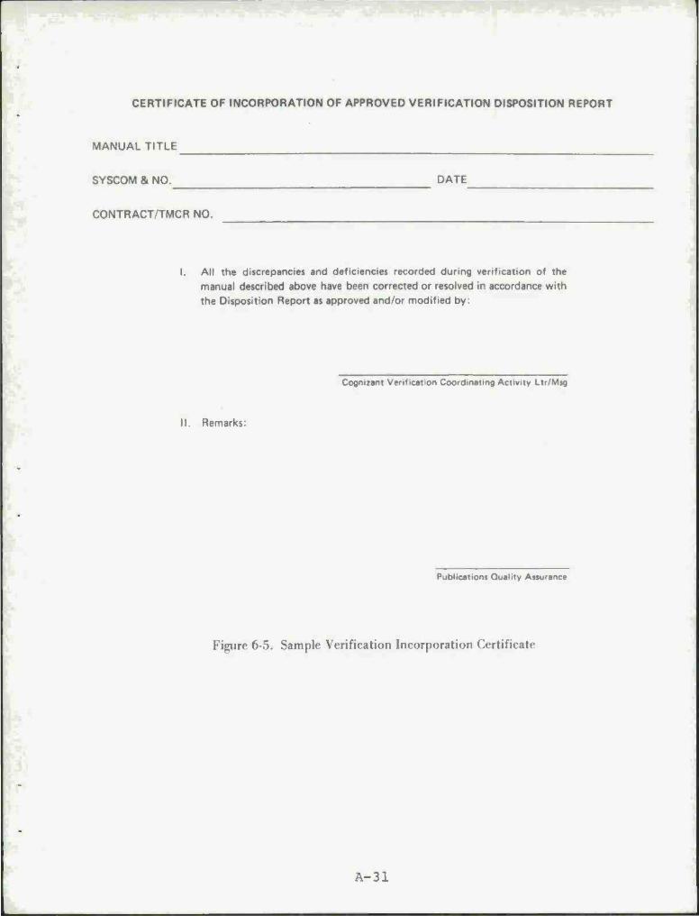
CERTIFICATE OF INCORPORATION OF APPROVED VERIFICATION DISPOSITION REPORT
MANUAL TITLE
SYSCOM & NO. DATE
CONTRACT/TMCR NO.
All the discrepancies and deficiencies recorded during verification of the manual described above have been corrected or resolved in accordance with the Disposition Report as approved and/or modified by:
Cognizant Verification Coordinating Activity Ltr/Msg
II. Remarks:
Publications Quality Assurance
Figure 6-5. Sample Verification Incorporation Certificate
A-31
8. GLOSSARY
ADEQUACY - A depth and scope of coverage sufficient to sup-
port all tasks and functions at the prescribed maintenance level
consistent with provisioning, support equipment selection, and
the approved weapon system/item support plan. In Illustrated
Parts Breakdown (IPB's), a parts listing and breakdown sufficient
to support all intermediate and depot level repairables plus a
complete listing of all parts and materials required to support
items coded for assembly or manufacture at intermediate or depot
level.
COPY FREEZE DATE - Date that the contractor and procuring
activity decides no more additions, deletions and changes will be
accepted to the publications material. Additions, deletions and
changes after that date will be accumulated for preparation of a
subsequent change or revision of the publication.
DEFENSE CONTRACT ADMINISTRATION SERVICES (DCAS) - The Govern-
ment activity designated as contract administrator and having
responsibility for acceptance of the manuals delivered to the Navy
by a preparing activity.
GROUP ASSEMBLY PARTS LIST (GAPL) - A breakdown of all systems,
assemblies, and subassemblies which can be disassembled, reassem-
bled, or replaced and are contained in the end article.
MAINTENANCE ENGINEERING ANALYSIS RECORD (MEAR) - The docu-
ment which specifies maintenance concept, maintenance requirements
and tasks, maintenance personnel and training requirements, support
equipment requirements, provisioning materials support, and pro-
vides the basis for technical manual approach and content. The
MEAR also provides the basis for support requirements status
reporting.
PREPARING ACTIVITY (PA) - The organization, whether a com-
mercial contractor or Cognizant Field Activity, holding a Tech-
nical Manual Contract Requirement (TMCR) or equivalent document
A-32

issued by the Procuring Agency for the preparation and delivery
of a technical manual or manuals. In this connection, a sub-
contractor, vendor, or government activity writing a manual for
the PA, or preparing manuscript data or input for the PA, is not
to be considered as the Preparing Activity.
PROCURING AGENCY - The appropriate Navy Systems Command as
represented by the Technical Manual Management Agency, Cognizant
Verification Coordinating Activity, Cognizant Field Activity
and/or the cognizant Defense Contract Administration Services.
PROVISIONING PARTS BREAKDOWN (PPB) - A document listing the
assemblies, subassemblies, and detail parts of an equipment to-
gether with assigned Source, Maintainability and Recoverability
(SMR) codes and the related data useful in selecting and program-
ming spare parts support. Also referred to in some documents as
a Provisioning Parts List.
TECHNICAL MANUAL (or Manual) - All types and forms of tech-
nical publications procured by TMCR (or equivalent) for issue
under the cognizance of the appropriate Systems Command.
TECHNICAL MANUAL CONTRACT REQUIREMENT (TMRC) - The document
which specifies the technical manuals required for support of an
equipment or system and also specifies related contractual
requirements.
TECHNICAL MANUAL MANAGEMENT AGENCY (TMMA) - The Naval Air
Technical Services Facility (Philadelphia) is the TMMA for the
Naval Air Systems Command. The Naval Ship Weapon System Engineer-
ing Station (Port Hueneme, California) is the TMMA for NAVSEA.
TMMT (Technical Manual Management Team) - A review team of
specially qualified publications personnel and technicians select-
ed to monitor preparing activity technical manual development and
preparation tasks. These teams are charged with the responsibility
of reviewing proposed technical manual requirements, analyzing and
A-33

recommending proposal technical data policy changes, specification
deviations and variations, and making appropriate recommendations
for approval or disapproval. In addition, they conduct in-process
and validation reviews.
A-34

CHECKLIST ATTACHMENT
FOR
IN-PROCESS REVIEW
PART I - PRESENTATION QUALITY

IN-PROCESS REVIEW CHECKLIST
PART I - PRESENTATION QUALITY
Page
1. ORGANIZATION I- 1 A. Principal Units and Work Packages I- 1 B. Arrangement within Sections or Packages ... I- 1 C. Composition Practices 1-2 D. Prose-Graphic Balance 1-3
2. PROSE COMPREHENSION 1-5 A. General Style Principles 1-5 B. Instructional Writing 1-6 C. Paragraphs 1-7 D. Sentences 1-7 E. Words 1-8 F. Non-Text Words and Phrases 1-10 G. Legibility 1-11
3. GRAPHICS COMPREHENSION 1-12 A. General Graphics Principles 1-12 B. Graphic Form Selection 1-14 C. Schematic and Wiring Diagram Practices . . . 1-15 D. Network Diagram Practices 1-16 E. Block Diagram Practices 1-17 F. Illustrations Practices 1-17 G. Freestanding or Series Pictorials 1-18 H. Tables Practices 1-18 I. Graphs Practices 1-20 J. Photograph Practices 1-20
4. READABILITY MEASUREMENT 1-21

1. ORGANIZATION
A. Principal Units and Work Packages
1. Manual organization is based on a hierarchy of main- tainable units or equipment.
2. Manual organization is compatible with a family tree or topdown breakdown of maintainable units or equipment.
3. Presentation of equipment or work units follows a logical organization such as order of use, mainte- nance hierarchy, or according to data flow.
4. A repair cycle overview is included.
5. The repair cycle overview is a diagrammatic repre- sentation of the succession of maintenance actions.
6. Diagrammatic overviews of system operation are used instead of or in support of prose system descriptions.
7. Several layers of overviews are used for larger systems.
8. "Refer to" problems are eliminated by consolidating all information about a maintainable unit into one package or section.
B. Arrangement within Sections or Packages
1. All information concerning a maintainable unit is consolidated into a single package.
2. The content, format, and sequence of information within a package is standardized.
3. A "local" table of contents is included to indicate material available within a section.
4. Pictorials are used to introduce the reader to ter- minology and physical features of the maintainable unit.
5. Tools, test equipment, personnel, and other resources are identified at the beginning of the section to which they apply.
N/A YES NO
1-1

1. ORGANIZATION
B. Arrangement within Sections or Packages (Continued)
5. System status, valve, meter switch settings, etc. are given at the beginning of the section or operation to which they apply.
7. Operating descriptions are included in each section or are contained as a whole under separate cover.
8. A topdown breakdown is provided to establish the re- ferents for the maintenance procedures of the section.
9. The location for any action is fixed before the de- scription of action is begun.
110 - Trouble analysis aids immediately follow operating descriptions.
Ill« Trouble analysis aids are sequenced or grouped in a logical order, e.g., • malfunction verification, • subsystem checks, • fault isolation.
|12. All nontroubleshooting procedures are included in the maintainable unit package as the final content item.
C. Composition Practices
1. There is approximately one heading for every two paragraphs.
2. Headings are set off by spacing, printed in bold lettering or otherwise emphasized.
3. The ratio of major headings to subheadings is not larger than 1 to 10.
4. Necessary cautions are listed at the beginning of the operation or, if there are a great many steps, during the operation.
5. Warnings and cautions are given in troubleshooting tables as the dangers are encountered.
6. An illustration is located within two pages after the initial reference to it.
N/A YES I NO
1-2

1. ORGANIZATION
C. Composition Practices (Continued)
7. There is consistency in the manual with respect to: a. formatting in troubleshooting aids, b. abbreviations, capitalizations, nomenclatures,
acronyms, c. numbering, d. references.
D. Prose-Graphic Balance
1. Approximately half of the material in the manual is text and half is graphic.
2. Any imbalance between narrative and pictorial favors pictorial in order to minimize procedural errors and performance time.
3. Pictorial is provided when steps refer to: a. a particular equipment location, b. the relationship between two or more equipment
items, c. a specific equipment manipulation (e.g., valve
rotation)f d. a test readout which is continuous (e.g., waveform)
rather than discrete (e.g., numerical value).
4. Both narrative and diagrammatic portions of Equipment Description materials are itemized, i.e. , listed, accentuated or emphasized.
5. Parts of components mentioned in the text are called out in an illustration.
6. Explanations are provided that simplify what is hap- pening and, therefore, what might be done to find and correct the situation quickly.
7. Pictorials should introduce terminology used in up- coming equipment descriptions.
8. Freestanding graphics are used in preference to text and illustrative graphics.
9. The text describes what tables contain and how to use them.
N/A YES NO
1-3

1. ORGANIZATION
D. Prose-Graphic Balance (Continued)
10. Instructions are provided for the use of complex or unusual figures.
11. Procedural help for complex portions of wiring and schematic diagrams is provided.
12. Procedural support is provided on how to troubleshoot complex portions of functional diagrams.
13. Instructions for use of figures are readily accessible.
14. Graphics are referred to in complete sentences (not parentheses).
15. Text referrals to graphics indicate where they are, e.g., Figure 5 on the opposite page.
N/A YES NO
1-4

2. PROSE COMPREHENSION
A. General Style Principles
1. A nomenclature pictorial is presented at the begin- ning of a section.
2. Pictorials are used to introduce key equipment ter- minology used in prose discussions.
3. Short, familiar names are used for hardware once it has been introduced. For example, after referring to a "videodisc proportional spacing word processor with high speed printer," further discussion can simply use the "word processor."
4. Abbreviations and acronyms are used sparingly.
5. Concrete and specific statements are used in place of abstract or general statements. • Poor - Accidental contact with these wires can
result in third degree burns. • Good - Touching these wires will severely burn
you.
6. Quantitative dimensions or values are given whenever the user must make a selection. • Poor - Drain the oil into a large container. • Good - Drain the oil into a 1 gallon container.
7. Examples are used rather than analogies.
8. On each 7x9 image-area page there are an average of: • 350 words, • five paragraphs, • two headings.
9. There is an average of one graphic to support each heading.
10. Text referrals to graphics indicate where they are, e.g., Figure 5 on the opposite page.
11. Graphics are referred to in complete sentences (not parentheses).
12. Instructions are provided for the use of complex or unusual figures.
N/A YES NO
1-5
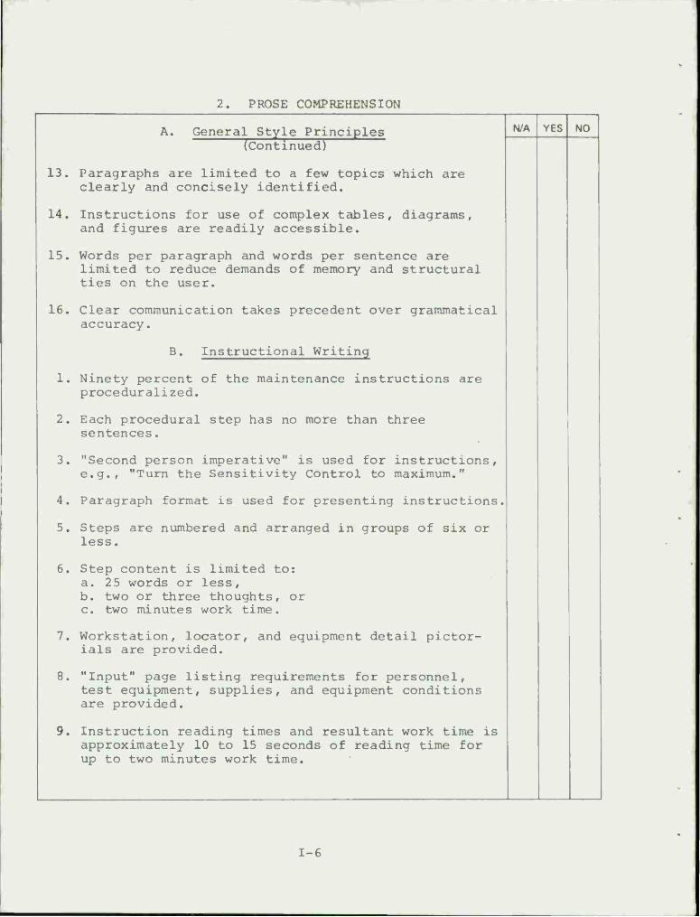
2. PROSE COMPREHENSION
A. General Style Principles (Continued)
13. Paragraphs are limited to a few topics which are clearly and concisely identified.
14. Instructions for use of complex tables, diagrams, and figures are readily accessible.
15. Words per paragraph and words per sentence are limited to reduce demands of memory and structural ties on the user.
16. Clear communication takes precedent over grammatical accuracy.
B. Instructional Writing
1. Ninety percent of the maintenance instructions are proceduralized.
2. Each procedural step has no more than three sentences.
3. "Second person imperative" is used for instructions, e.g., "Turn the Sensitivity Control to maximum."
4. Paragraph format is used for presenting instructions.
5. Steps are numbered and arranged in groups of six or less.
6. Step content is limited to: a. 25 words or less, b. two or three thoughts, or c. two minutes work time.
7. Workstation, locator, and equipment detail pictor- ials are provided.
8. "Input" page listing requirements for personnel, test equipment, supplies, and equipment conditions are provided.
9. Instruction reading times and resultant work time is approximately 10 to 15 seconds of reading time for up to two minutes work time.
N/A YES NO
1-6

2. PROSE COMPREHENSION
1.
C. Paragraphs
Short thought units or "chunks" of information are used in preference to longer units.
N/A YES NO
2. Paragraphs are short and have topic sentences.
3. Long sections of material start with a summary.
4. Graphics are in view as the related prose is read.
5. Paragraphs are limited to a few topics which are clearly and concisely identified.
6. Each paragraph of prose material is limited to no more than three main points. Five or more key points in a paragraph may be presented better as a table.
7. Topic sentences in a paragraph are especially clear and concise.
8. Paragraphs are limited to 45 to 60 words.
9. Peak stress emphasis (underlining, italics, etc.) is used where lengthy paragraphs cannot be avoided.
10. Paragraph headings are used to facilitate access and to identify the type of material which will follow.
11. Paragraph headings are consistent with expectancies established by overviews.
12. Fifty percent of the subparagraphs have headings or lead ins.
D. Sentences
1. Sentences generally contain a single idea or thought.
2. Sentences are limited to 17 to 20 words.
3. Common and unambiguous verbs are used.
4. Compound or complex sentences are changed to simple sentences.
5. Lengthy sentences are avoided.
1-7
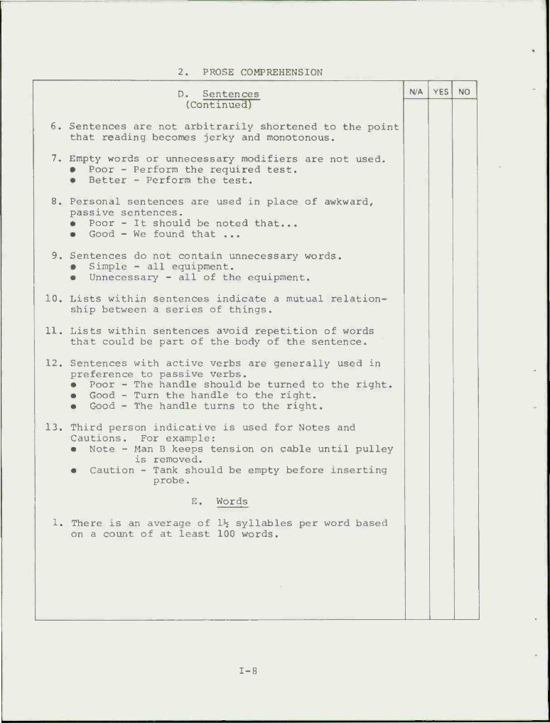
2. PROSE COMPREHENSION
D. Sentences (Continued)
6. Sentences are not arbitrarily shortened to the point that reading becomes jerky and monotonous.
7. Empty words or unnecessary modifiers are not used. • Poor - Perform the required test. • Better - Perform the test.
8. Personal sentences are used in place of awkward, passive sentences. • Poor - It should be noted that... • Good - We found that ...
9. Sentences do not contain unnecessary words. • Simple - all equipment. • Unnecessary - all of the equipment.
10. Lists within sentences indicate a mutual relation- ship between a series of things.
11. Lists within sentences avoid repetition of words that could be part of the body of the sentence.
12. Sentences with active verbs are generally used in preference to passive verbs. • Poor - The handle should be turned to the right. • Good - Turn the handle to the right. • Good - The handle turns to the right.
13. Third person indicative is used for Notes and Cautions. For example: • Note - Man B keeps tension on cable until pulley
is removed. • Caution - Tank should be empty before inserting
probe.
E. Words
1. There is an average of 1*$ syllables per word based on a count of at least 100 words.
N/A YES NO
1-8

2. PROSE COMPREHENSION
E. Words (Continued)
H/A YES NO
2. Lengthy words are eliminated or "diluted." Use com- mon words in place of less familiar words.
Simple Awkward
about as to, with regard to after subsequent to because inasmuch as, for the reason that call for necessitate, require enough sufficient find out ascertain, determine for for the purpose of get acquire, obtain, receive if in the event that now at this time, presently of relative to, with regard to since inasmuch as use utilize
3. Simple prepositions are used.
Simple Awkward
like along the lines of to in order to by, under in accordance with to with a view to about with reference to so that with the result that
4. Simple connectives are used.
Simple Awkward
so accordingly so consequently so for this reason then furthermore so hence in other words that is to say for example more specifically
1-9

2. PROSE COMPREHENSION
F. Non-Text Words and Phrases
1. Labels and titles of graphics indicate what they are about.
2. Nomenclature in the text is defined the first time it is used.
3. Headings are no more than 3 or 4 words.
4. Text headings and subheadings accurately describe the text material.
5. Headings and subheadings divide the text into coher- ent, self-contained units of information.
6. Headings and subheadings relate logically within and across sections.
7. Headings and subheadings are easy to locate in the text.
8. Out of text notes, cautions, and warnings are easily visible by the border, title, color, or spacing, but in a consistent manner.
9. Notes, cautions, and warnings are presented at the beginning of an operation before the relevant steps.
110. Notes, cautions, and warnings are presented during an operation if there are a great many steps.
111. Special symbols are explained.
112. Legends, explanatory notes, etc. are descriptive.
13. Legends, explanatory notes, etc. are readily accessible.
114. Legends, explanatory notes, etc. do not mask or ob- scure figure parts.
115. Legends, explanatory notes, etc. do not contain excess| verbiage.
N/A YES NO
1-10

2. Prose Comprehension
G. Legibility
1. Page layout generally enhances reading speed and comprehension.
2. Double column format is used for prose.
3. Ideal line length is between 14 picas (2-5/16") and 23 picas (3-13/16"). One pica equals .166 inches.
4. Roman text type face is used for good legibility.
5. For good legibility, 10 or 11 point (one point = .0138 inches) type is used with 2 point leading.
6. Word labels comply with minimum type size standards.
7. Print size and type are adequate for conditions under which figures will be used. Consider such things as illumination, vibration, and wind.
8. The margins are at least one-half inch wide.
9. There is extra space between paragraphs.
10. Lines (as in circuit diagrams and MDCs) are not over- crowded (minimal separation is 1/16").
11. Figures do not appear cluttered". They can be read clearly under estimated conditions of illumination and distance for use.
N/A YES NO
1-11

3. GRAPHICS COMPREHENSION
A. General Graphics Principles
1. General appearance of each graphic page is good. There are no smudges, white space is evenly distri- buted and graphics appear uncrowded.
2. Relation of elements on a page is clear.
3. Graphic fidelity is kept to a minimum for the task at hand.
4. Scope and level of detail is not excessive for the task at hand.
5. Graphics titles (if appropriate) are descriptive of the graphic.
6. Graphics can be read clearly under estimated condi- tions of distance for user and illumination. General- ly, smallest called-out feature is clear when the graphic is viewed at about 4 feet under the illumina- tion available when the task is performed.
7. The line of regard of a pictorial is the direction from which the technician will view the item.
8. Line of regard in related figures is logical or varia- tion is explained.
9. The amount of information included in an image area is controlled to prevent clutter (figure does not appear jammed) .
|10. Half-tone figures are sharp, not murky.
111. Shading or blacking is used to indicate and locate items.
|l2. Shading is not excessive.
13. Legends and notes are located in the left-hand corner of an illustration.
|14. Special symbols are explained.
|15. Legends, explanatory notes, etc. are descriptive.
|16. Legends, explanatory notes, etc. are readily accessible.
N/A YES NO
1-12

3. GRAPHICS COMPREHENSION
A. General Graphics Principles (Continued)
17. Legends, explanatory notes, etc, do not mask or ob- scure figure parts.
L8. Legends, explanatory notes, etc. do not contain excess verbiage.
L9. Legends and keys are repeated on each page of multi- page figures.
20. Relationship between sequential pages of graphics is logical and obvious or explained.
21. Points of continuity between multipage graphics (exit and entry points) are obvious.
22. Captions, call-outs and labels are clearly differentiable.
2 3. Captions are accurate, descriptive, and located so that there is no confusion in the item to which caption refers.
24. Word labels comply with minimum type size standards.
25. Labels are used to show direction.
26. Arrows and lines do not cross each other.
27. Arrows and lines are clear and not broken.
28. There is no uncertainty in what is pointed to or connected by arrows and lines.
29. Call-outs, labels, arrows, etc. do not cover or ob- scure meaning.
30. Multiple call-outs, labels, etc. are aligned.
31. Direction arrows are used to orient the viewer, e.g., FWD, REAR.
32. Arrows are used to indicate motion.
33. Arrows and call-outs are used to emphasize key points of a pictorial.
N/A YES NO
1-13
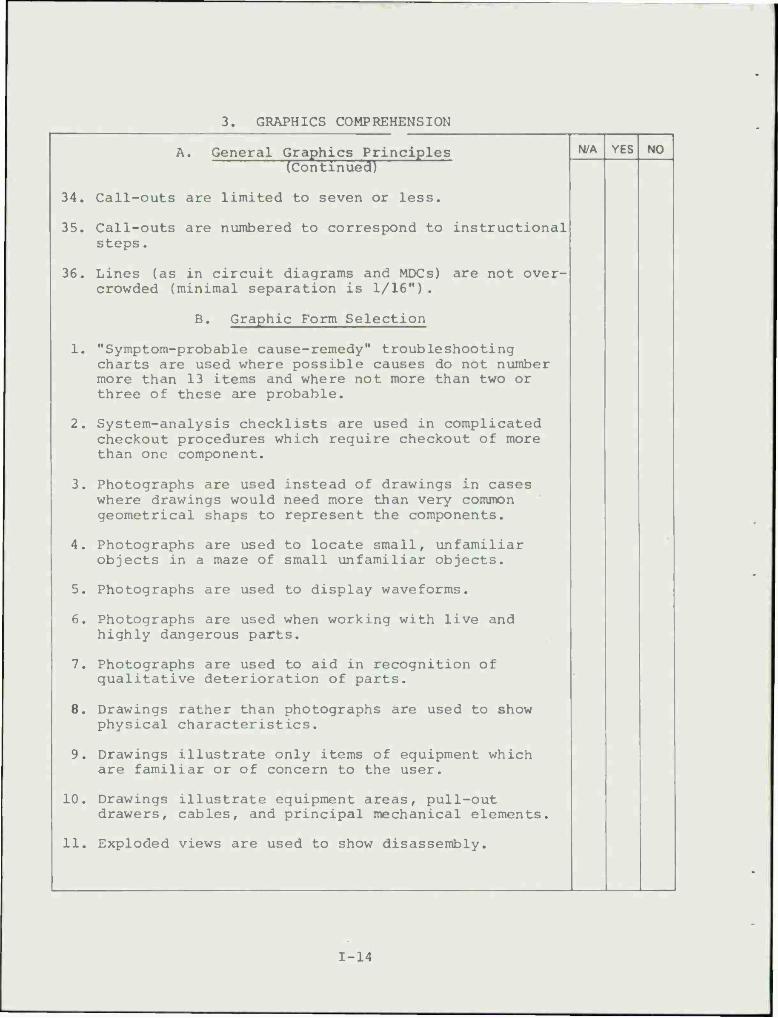
3. GRAPHICS COMPREHENSION
A. General Graphics Principles (Continued)
34. Call-outs are limited to seven or less.
35. Call-outs are numbered to correspond to instructional steps.
36. Lines (as in circuit diagrams and MDCs) are not over- crowded (minimal separation is 1/16").
B. Graphic Form Selection
1. "Symptom-probable cause-remedy" troubleshooting charts are used where possible causes do not number more than 13 items and where not more than two or three of these are probable.
2. System-analysis checklists are used in complicated checkout procedures which require checkout of more than one component.
3. Photographs are used instead of drawings in cases where drawings would need more than very common geometrical snaps to represent the components.
4. Photographs are used to locate small, unfamiliar objects in a maze of small unfamiliar objects.
5. Photographs are used to display waveforms.
6. Photographs are used when working with live and highly dangerous parts.
7. Photographs are used to aid in recognition of qualitative deterioration of parts.
8. Drawings rather than photographs are used to show physical characteristics.
9. Drawings illustrate only items of equipment which are familiar or of concern to the user.
10. Drawings illustrate equipment areas, pull-out drawers, cables, and principal mechanical elements.
11. Exploded views are used to show disassembly.
N/A YES NO
1-14
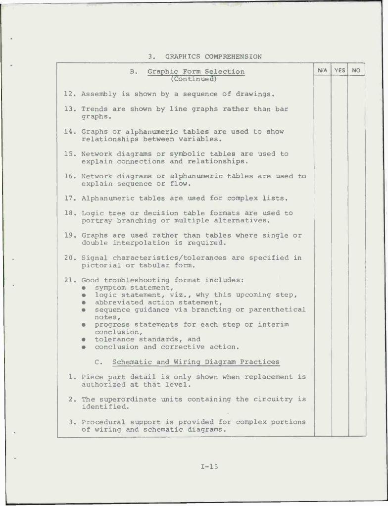
3. GRAPHICS COMPREHENSION
B. Graphic Form Selection (Continued)
12. Assembly is shown by a sequence of drawings.
13. Trends are shown by line graphs rather than bar graphs.
14. Graphs or alphanumeric tables are used to show relationships between variables.
15. Network diagrams or symbolic tables are used to explain connections and relationships.
16. Network diagrams or alphanumeric tables are used to explain sequence or flow.
17. Alphanumeric tables are used for complex lists.
18. Logic tree or decision table formats are used to portray branching or multiple alternatives.
19. Graphs are used rather than tables where single or double interpolation is required.
20. Signal characteristics/tolerances are specified in pictorial or tabular form.
21. Good troubleshooting format includes: • symptom statement, • logic statement, viz., why this upcoming step, • abbreviated action statement, • sequence guidance via branching or parenthetical
notes, • progress statements for each step or interim
conclusion, • tolerance standards, and • conclusion and corrective action.
C. Schematic and Wiring Diagram Practices
1. Piece part detail is only shown when replacement is authorized at that level.
2. The superordinate units containing the circuitry is identified.
3. Procedural support is provided for complex portions of wiring and schematic diagrams.
N/A YES NO
1-15

3. GRAPHICS COMPREHENSION
C. Schematic and Wiring Diagram Practices (Continued)
4. Word labels comply with minimum type size standards, usually 10 point.
5. Hard copy diagrams are available to facilitate signal tracing.
6. Points of continuity are labeled between multiple page presentations.
7. Lines are continuous and unbroken.
8. Standard electric/electronic symbology is used.
9. Schematic density should be limited to an average of three elements per square inch or less; there are no more than an average of four intersecting lines per square inch.
10. At least 1/8" separation is provided between parallel lines.
D. Network Diagram Practices
1. Different information elements on diagrams are sepa- rated by distance, shading, boxes, or some other method.
2. The information elements of network diagrams are either familiar symbols, readily understandable alphanumerics or labels, or pictorials.
3. MDCs connectives and leader lines do not overlap function codes.
4. MDCs function codes do not overlap each other.
5. Diagrams use sequencing codes to help in locating work areas and parts.
6. Network diagrams contain only necessary detail for the task at hand.
7. Diagrams are not oversized. There are several small diagrams in preference to one large, unwieldy one.
N/A YES NO
1-16

3. GRAPHICS COMPREHENSION
D. Network Diagram Practices N/A YES NO fcöntlnuecn
8. Procedural support is provided on how to troubleshoot complex portions of functional diagrams.
9. Hard copy is available to facilitate signal tracing.
E. Block Diagram Practices
1. Direction arrows are used to show flow.
2. Flow is left to right and top to bottom.
3. Height to width ratio of 2 to 3 is used for function- al flow blocks.
4. Diagrams are organized from left to right or top to bottom.
5. Inputs and outputs are identified as such.
6. Inputs are on the left and outputs are on the right in block diagrams.
7. Inputs and outputs are clearly defined or labeled for each block.
F. Illustrations Practices
1. Line drawings are used to emphasize relevant items rather than portray faithful physical fidelity.
2. Relation of parts in exploded views is indicated by axis lines or other obvious connecting lines.
3. Any feature of a drawing referred to in the text is at least as large as the text type size.
4. Important dimensions of drawing are at least 1/10".
5. Call-outs are used to refer to parts of illustrations.
6. All lines on a pictorial are at least 1/8" apart.
7. Non-standard symbols (according to MIL-STD-100) are explained in a legend on the illustration.
1-17

3. GRAPHICS COMPREHENSION
F. Illustrations Practices (Continued)
8. The point of regard for drawings show equipment from the technician's view.
9. There are no more than five called out items per square inch.
G. Freestanding or Series Pictorials
1. In a series of drawings, the first one provides ori- entation with respect to the major end item of equipment.
2. Arrows or lines show progression from less to more detailed drawings.
3. Relation of elements in a series of pages of sequen- tial figures is clear.
4. Drawings progress from contextual (equipment plus surrounds) to enlargements to exploded views when supporting procedures.
5. In a series of drawings, the first one provides ori- entation with respect to the entire system (e.g., aircraft).
6. Each time the technician must move to a new location, a new contextual (locator) or workstation graphic is given.
7. Freestanding pictorials have information on the graphic itself when possible - not in the text.
H. Tables Practices
1. Interpolation is not required in numerical look-up tables.
2. Title reflects content variables.
3. Headings are clear and scale units are included as needed in headings.
4. Data elements within the table are easily related to the row and column headings which specify their location.
N/A YES NO
1-18

3. GRAPHICS COMPREHENSION
5.
H. Tables Practices
Elements within the table are roughly equal in infor- mation content (or gross differences are justified by the nature of the table).
N/A YES NO
6. If there are multielement cells, elements within cells are clearly separable (e.g., by type size or type character).
7. Information follows a natural order or scaling (e.g., or elements within a row/column are related to each other) .
8. If the items in a table are measurable, the scaling unit is specified in a heading or beside each entry.
9. Inputs into tables are readily apparent.
10. Element content is intelligible and makes sense in context.
LI. Column headings are aligned with elements and adja- cent to them.
L2. Units are specified in column heads.
13. Rows either have row headings or labeling is not needed because of an intrinsic order.
14. Row entries are arranged in groups of six or less.
15. Row entries are alphabetized if necessary.
16. Elements are aligned within column and row.
17. If a table is comprised of numbers, the numbers are aligned on a decimal point or right-hand justified.
18. The vertical dimension of a table is greater than the horizontal dimension.
19. There are fewer columns than rows.
20. There are no empty rows or columns.
21. Tables are not compressed and information is easy to find. In general, there should be 25% white space.
1-19

3. GRAPHICS COMPREHENSION
H. Tables Practices (Continued)
|22. The table is enclosed in a border.
I. Graphs Practices
1. Graphs usually have only a single concept.
2. Comparison between data is shown on the same graph.
3. Graph scales do not distort the intended relationships.
4. Grid interval of .1 to .3 inch is used (inch minimum).
5. Grid lines are 0.015 to 0.0125 inch wide.
6. Axes are oriented naturally, e.g., altitude on verti- cal axis.
7. Title reflects graph variables.
8. Instructions and illustrations are provided for use with complex graphs.
9. A legend is provided for non-standard symbols.
|10. Multilayed bars of a graph are connected with lines to emphasize comparisons.
111. Graphs are enclosed in a border.
J. Photograph Practices
1. Photographs show equipment from the technician's view.
2. Photographic views indicate uncommon shape or danger- ous components.
N/A YES NO
Photographs are retouched to help orientation of the workers.
Photographs are retouched to keep fidelity and detail to a minimum.
Photographs locate small, unfamiliar objects in a maze of pieces.
1-20

4. READABILITY MEASUREMENT
Testing technical material to obtain a "readability" score is not a standardized or agreed upon procedure. Furthermore, readability means different things to dif- ferent people. However, readability is an important factor in quality assurance. Therefore, a procedure for calculating the Fog Index, a measure of the understand- ability of reading matter, is included as a part of these checklists. The Fog Index is easy to apply and to calcu- late. It provides a direct measure of readability in terms of educational level.
THE FOG INDEX
Purpose
Overall measure of readability of test material.
Procedure
Identify several sections containing written text. Scan each section for the types of writing it contains. Select two samples for each type of writing within each section. Record the selected samples of the Fog Index Worksheet. Use the Worksheet for the following.
Calculate average sentence length. Count 100 words; if not at the end of a sentence, stop the count with the end of the sentence near- est 100 words. Record the number of words and sentences.
# words ASL (average sentence length) = # sentences
Reconsider the first 100 words of the approximately 100-word sample. Exclude words which are equipment names or nomenclature, and extend the sample by the number of words needed to total 100 again.
Count the number of words of three syllables or more in the extended 100-word sample. Don't count words that are three or more syllables because an "ed" or "ing" has been added to them.
%HW (hard words) = number of 3 or more syllable words counted.
Calculate the Fog Index. FI - (ASL + %HW) x 0.4.
WA YES NO
1-21

4. READABILITY MEASUREMENT
Results N/A YES NO
The Fog Index values agree closely with educational levels of reading difficulty. A Fog Index of 12 means that students at the 12th grade level could be expected to answer correctly 90% of a set of questions testing their reading of the material. For the component parts of the Fog Index, the averages are as follows:
School Grade ASL %HW Total FI
12 20 9 29 11.6 10 18 6 24 9.6
8 15 5 20 8.0 6 14 3 17 6.8
1-22

FOG INDEX WORKSHEET
Publication Title and Number Reviewed by
Data
EVALUATION STANDARDS
NOTE: Select two samples at random for each type of writing with each section.
School Grade
Average Sen- tence Length (ASL)
Average % Hard Words (% HW)
Total Fog Index
12
10 8 6
20 18 15 14
9
6 5 3
29 24 20 17
11.6 9.6 8.0 6.8
Section Page
Avg. Sentence Length (ASL) %
HW
TOTAL (ASL + %HW)
Fog Index
0.4 (TOTAL) Number
Words Number
Sentences ASL
1-23


CHECKLIST ATTACHMENT
FOR
IN-PROCESS REVIEW
PART II - JOB PERFORMANCE ADEQUACY

IN PROCESS REVIEW CHECKLISTS - PART II
-JOB PERFORMANCE ADEQUACY-
Page
1. ACCESS AND SEARCH II-l
A. Identification II-l
B. Sections or Packages II-l
C. Table of Contents and Headings II-2
D. Index II-2
E. Reference Compliance II-3
2. USABILITY AND ACCEPTANCE II-5
A. Information Content Adequacy II-5
B. Job Relevance and Efficiency II-7
C. Workplace and User Compatibility II-7
D. Technical Scope and Accuracy II-8

1. ACCESS AND SEARCH
A. Identification
1. The title page reveals the purpose of the manual and the system or equipment for which it is used.
2. A full page illustration of the equipment is provided near the front of the manual.
3. Manual breakdown is based on a hierarchy of maintain- able units or work packages.
4. A family tree or topdown breakdown of maintainable units is provided.
5. The manual includes charts or tables showing the interchangeability of components, cables, and assem- blies for particular systems, and they are easy to locate.
6. Items do in fact appear in the text when they are listed in the: a. table of contents, b. list of figures, c. list of tables, d. index.
B. Sections or Packages
1. A "local" table of contents is used to indicate material available within a section or package.
2. Test equipment is listed in tables to show how and when it is needed.
3. Tables show availability of test points for use in trouble-shooting procedures.
4. A repair cycle overview is included. This is a dia- grammatic representation of the succession of maintenance actions.
5. Illustrations are within 2 pages of where they are referenced in the text.
6. There are no "refer to's" outside of a section in the manual.
N/A YES NO
II-l

1. ACCESS AND SEARCH
B. Sections or Packages (Continued)
7. Internal references (e.g., "see," "refer to") are used rather than repetition when there are ten or more lines of text.
8. Internal references are easy to locate and there are no secondary referrals.
C. Table of Contents and Headings
1. The table of contents has a logical sequence from topic to topic.
2. The table of contents consistently lists all text headings of the same level.
3. Each heading and subheading is referenced at least once in the table of contents or index.
4. The minimum number of table of contents entries is one per page of manual content.
5. Paragraph headings are consistent with expectancies established by overviews.
6. Text headings are informative.
7. Headings are used to facilitate access and to iden- tify the type of material which will follow.
8. Fifty percent of the subparagraphs have headings or lead-ins.
9. The average number of headings per page is two.
D. Index
1. Any text heading not in the table of contents is in the index.
2. The minimum number of index headings is one per page of manual content.
3. The index is set up in alphabetical order.
N/A YES NO
II-2

1. ACCESS AND SEARCH
D. Index (Continued)
4. The index is set up in a manner as to make the loca- tion of trouble-shooting procedures for individual problems possible.
5. Symptoms are indexed either in the back or front of the manual.
6. As some items can be located under several headings, there are notations under main headings showing where they may be found.
7. The index contains as a minimum listings of subsys- tems, equipment and items, maintainable assemblies, or job functions.
8. The average ratio of headings to subheadings is no greater than 1 to 10.
9. The manual includes a glossary of technical terms.
E. Reference Compliance
1. Official part number and nomenclature used on title page to identify the technical manual. (MIL-M-38784)
2. Inclusion of listing of technical directives (changes and bulletins) covered by the manual.
3. Applicable safety precautions included. (MIL-M-38784)
4. All abbreviations and technical terms fully explained and identified. (MIL-M-38784)
5. Nomenclature consistent within the manual and with directly related publications. (MIL-M-38784)
6. In the case of IPB's, source control, specification control and vendor part numbers listed in the GAPL according to MIL-H-8910.
7. Source codes listed in the numerical index (IPB).
8. IPB numerical index contains all part numbers listed in the PPB. (MIL-H-8910)
N/A YES NO
II-3

1. ACCESS AND SEARCH
E. Reference Compliance (Continued)
9. Breakdowns and GAPL in the IPB consistent with source coding.
10. References made to other manuals in the IPB GAPL when appropriate.
11. Material listed in the GAPL of the IPB for all items coded for local manufacture.
12. Adequate instructions included in the maintenance manual for the fabrication of items coded for local manufacture.
N/A YES NO
II-4

2. USABILITY AND ACCEPTANCE
A. Information Content Adequacy
1. Initial system conditions for maintenance activities
N/A YES NO
are specifically identified for such factors as: a. gaining access, b. removing fluids, c. pressurizing/depressurizing, d. raising/lowering, e. energizing/de-energizing, f. warm up/cool down.
2. Initial equipment conditions, prior to operations or maintenance, are specifically identified for such factors as: a. switch position, b. valve position, c. recorder settings, d. meter settings.
3. Maintenance checkpoints are identified and expanded on in terms of: a. their location, b. appropriate measurement equipment, c. tolerances at each checkpoint, d. parameters for alternate modes, e. unusual procedures or cautions.
4. Special instructions are included for hazards, warn- ings and cautions, or other unique situations such as: a. problems in seeing and recognizing gross
indications, b. problems in reading quantitative values, c. problems in detecting relative motion between
components, d. problems in reading or interpreting oscilloscope
patterns or wave forms, e. noting visually detectable defects, f. presence or absence of unique sounds and
vibrations, g. discriminating characteristics of sounds, i.e.,
pitch, loudness, roughness, duration, h. special odors, i.e., burnt insulation, leaking
fluids, exhaust gases, i. critical decisions in selecting next step or task, j. special calculations, k. areas requiring technician's judgments, 1. problems in switch activation, m. problems in adjusting controls
II-5

2. USABILITY AND ACCEPTANCE
A. Information Content Adequacy (Continued)
n. problems in performing gross body movements, o. problems in performing fine coordinated movements.
5. Special tools, equipment, and supplies needed for maintenance are identified to permit the technician to obtain them before going to the work site. This includes: a. tools not normally included in tool kit, b. test equipment, c. special supplies and expendables, d. special forms.
6. Personnel requirements are clear with respect to the following: a. skills required (an extra pair of hands or a tech-
nical specialist), b. communication requirements, c. sequential and simultaneous performance
requirements.
7. Equipment identification and location information is provided in terms of contextual drawings; use of en- largements; or exploded views.
8. Preparation of the work area, including arrangement and location of support items, personnel, and tech- nical materials, is clearly presented.
9. Work station location and personnel position por- trayals are clearly illustrated or described in terms of standard nomenclature and/or readily recognizable features.
10. Adequate instructions are included in the maintenance manual for the fabrication of items coded for local manufacture.
11. Coverage is compatible with MEARS, source coding and companion manuals. (Sampling)
12. Follow-on actions are identified for each possible outcome of the maintenance or operation package.
N/A YES NO
II-6

2. USABILITY AND ACCEPTANCE
B. Job Relevance and Efficiency
1. All information concerning a maintainable unit is consolidated into a single package.
2. Manual sections or packages contain only that infor- mation required to support job performance.
3. Information not relevant to the job or excess detail is eliminated.
4. All items of test equipment and tools needed in an operation are listed at the beginning of that operation.
5. All personnel needed to assist in the operation are listed by title with an indication of what and when they are to perform.
6. Pictorials to introduce the reader to terminology and features of the maintainable unit are provided.
7. The location of any action is fixed before the de- scription of action is begun.
8. Cautions and Warnings are clearly identified by color, borders, spacing, or some other emphasis feature.
9. The content, format, and sequence of information within a package is standardized.
110. Graphics and related prose are arranged for simultan- eous viewing.
111. Hard copy of trouble-shooting aids is provided to facilitate use at the job site.
C. Workplace and User Compatibility
1. The manual specifies what might be done to make the working situation as ideal as possible.
2. Specific instructions are given for special mainte- nance which might be required in unusual climatic conditions of cold, heat, wind, altitude, and noise.
3. The manual is constructed so as to allow the removal and addition of pages.
N/A YES NO
II-7

2. USABILITY AND ACCEPTANCE
C. Workplace and User Compatibility (Continued)
4. The manual is constructed to be convenient in size as regards working space (pocket-size = 5" x 8M x iy, desk size = 8*5" x 11") .
5. Foldouts are not used or are minimized.
6. Foldout pages are consistent in the "Pyramid Gate Fold."
7. A highly reflective matte rather than glossy paper is used.
D. Technical Scope and Accuracy
Technical scope and accuracy is not amenable to a checklist type of review. Tests for scope and accuracy are more appropriately a part of Validation and Verifi- cation rather than In-Process Review. The questions of concern are:
1. Is the information in the manual technically accurate?
2. Is there enough information in the manual to adequately support job performance?
As part of In-Process Review, however, a form of adequacy check may be performed. NAVAIR 00-25-600 defines an adequacy check and suggests a procedure as indicated below.
The objective of an adequacy check is to de- termine the degree to which depth and scope of coverage in maintenance manuals, and the parts listing and breakdown in IPB's are sufficient to support repairables, replaceables and items to be assembled or manufactured within the Navy establishment.
To perform an adequacy check, it is advan- tageous to work in groups, one person working with PPB, one with the IPB and one with the maintenance manual. The person with the PPB searches out items coded repairable, replace- able, to be assembled or manufactured. The part number and nomenclature of these items is called out, along with the source code,
N/A YES NO
II-8

2. USABILITY AND ACCEPTANCE
D. Technical Scope and Accuracy (Continued)
and the person working with the IPB deter- mines if it contains the proper artwork and parts breakdown while the person working the maintenance manual ascertains if the depth of coverage supports the source/maintainability/ recovery code. At the same time, the approved support equipment listing can be checked to as- sure that support equipment called out in the maintenance procedure is approved and compatible.
N/A YES NO
II-9


INITIAL DISTRIBUT
Copie 8
1 OASD (I&L) Mr. R. Shorey
1 DMSSO Mr. M. Zupan
1 ODDR&E LTC . Henry L. Taylor
ON
Copies
AMC Mr. R. Graves (MA-SM4)
TRADOC COL. F. A. Hart
ARI Dr. Otto Kahn Dr. Joseph Ward
ARMY HEL Mr. D. S. Mackey (AMXHE HEL)
AMXMD-EP Mr. Roy Post Mr. Art Rulon
CNO Mr. B. Gruber (OP-401G) Mr. D. Thunnan (OP-991C)
CNET Dr. W. Scanland (N52) Mr. Bob Jones (N 521)
CNETS Mr. E. L. Leech (Code 01) Mr. Joe Barron (Code 3314)
CNTT Dr. N. Kerr (Code 0101)
NTEC Dr. William King (Code N215) Mr. Ralph Laugen (Code N423)
TAEG Dr. R. Braby (NOOT)
OPTEVFOR CDR. I. Donovan (Code 32)
NAVMAT Mr. A. I. Rubinstein (Code 0344) Mr. B. O'Hern (Code 0422)
BUPERS CDR. F. Lull (Pers-Or) LCDR. L. W. Beguin (Pers-2S)
NADC LCDR. Thelsen
NELC Mr. J. Slaughter (Code 3000)
NUC Mr. B. Saltzer
NWC Mr. Bill Paff (Code 5535)
NUSC Mr. Phil Danforth (EA 311)
NAVELEX (Code 490)
NAVSUP Mr. George B. Bernstein (Code 0431C) Mr. H. Burby (Code 10)
WAVSEA Mr. Henry Hill (00G) Mr. W. G. Shihda (Code 0463) Mr. M. Amico (PMS 306121) Mr. D. Baird (Code 660F) Mr. J. Jenkins (Code 660F) Mr. John Taylor (PMS 403-05) Mr. S. Myers (Code 6181C)
NAVSEC MECH Mr. George Turek (Code 880)
NAVAIR Mr. William G. Muller (Code 04A4) Mr. H. Keneman (Code 04A4) Mr. D. S. Hurst (Code 340C) Dr. L. Miller (Code 413) Mr. T. Pugh (Code 5312H)
Copies
NPRDC Dr. T. Curran
NWESA Mr. Leon Horn (ESA-712) Mr. John Bartholomew (ESA-83)
NAVPHOCEN Mr. Glen Bull (RDQ)
NSWSES Mr. C. M. Root (Code 5001)
NSDSA Mr. Ken Radcllff (Code 5700)
USAFHQ(LGYE) Mr. R. W. Welsh
AFilRL(WPAFB) Mr. Klesch COL. J. Ostromlnskl (ASD/SMA) Mr. Bob Rose (MMOMP)
1 AFHRL(LAFB) Dr. Ron Burkett
2 DLSIE
12 DDC
CENTER DISTRIBUTION
Copies Code
1 18
1 1809.1
1 183
1 184
1 185
Copies Code
186
1861
186A
1863
188
2784


I
»