Embed Size (px)
Citation preview
SPECORD® PC 200 / 205 / 210 / 250 UV VIS Spectrophotometer
Analytik Jena AG Kundendienst Konrad-Zuse-Str. 1 07745 Jena
Phone: Hotline: + 49 (0) 3641 77 74 07 Fax: + 49 (0) 3641 77 74 49 E-Mail: [email protected] General information about Analytik Jena AG on the internet: http://www.analytik-jena.de Copyrights and Trademarks Microsoft, Windows XP, Windows NT, Windows 2000, MS Excel are registered trademarks of Microsoft Corp.
Publication No.: 221:416.23 Edition – April 2005 Technical documentation made by: Analytik Jena AG This documentation describes the state of this product at the time of publishing. It need not necessarily agree with future versions of the product. Subject to change! © Copyright 2005 Analytik Jena AG
SPECORD® Contents
Contents 1 Introduction .....................................................................3 1.1 Intended use of the SPECORD.............................................................3 1.2 Notes on the User's Manual ..................................................................4
2 Safety notes .....................................................................5 2.1 Warning labels on SPECORD...............................................................5 2.2 General safety regulations ....................................................................5
3 Technical data of the spectrophotometers ...................9 3.1 Optical data of SPECORD ....................................................................9 3.2 General technical data of SPECORD .................................................11
4 Device description and operating principle ................13 4.1 Mechanical design of SPECORD .......................................................13 4.2 Design of subassemblies ....................................................................14 4.2.1 Light sources..................................................................................................14 4.2.2 Spectrometer system and photometer section ...............................................16 4.2.3 Sample compartment .....................................................................................17
5 Installation and transport conditions ..........................19 6 Installation and start-up................................................21 6.1 Connectors and display elements.......................................................21 6.2 Removing the transport lock ...............................................................23 6.3 Connecting the SPECORD .................................................................24 6.4 Start-up................................................................................................25 6.5 Switching the device off ......................................................................26 6.5.1 Switching the deuterium lamp off ...................................................................26 6.5.2 Switching the SPECORD off ..........................................................................26
7 Accessories ...................................................................27 7.1 Standard cell holders ..........................................................................27 7.2 Receptacle for cells with turbid samples.............................................28 7.3 Additional accessories ........................................................................29
8 Care, maintenance, lamp change.................................31 8.1 Care and maintenance........................................................................31 8.2 Cleaning ..............................................................................................31 8.3 Changing lamps ..................................................................................32 8.3.1 Note on the service life of lamps ....................................................................32 8.3.2 Opening the flap of the lamp compartment ....................................................32 8.3.3 Changing the deuterium lamp ........................................................................35 8.3.4 Changing the halogen lamp ...........................................................................37 8.4 Changing the desiccator .....................................................................39 8.5 Changing fuses ...................................................................................39
9 Disposal .........................................................................41 10 Index to Illustrations .....................................................43 11 Index to Overviews........................................................43
SPECORD® 200/205/210/250 User's Manual – Edition 04/2005 Page 1 Analytik Jena AG

SPECORD® Introduction Intended use of the SPECORD
1 Introduction
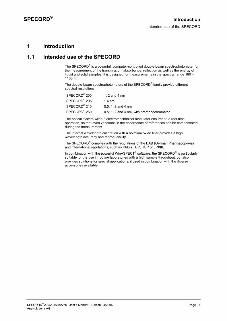
1.1 Intended use of the SPECORD The SPECORD® is a powerful, computer-controlled double-beam spectrophotometer for the measurement of the transmission, absorbance, reflection as well as the energy of liquid and solid samples. It is designed for measurements in the spectral range 190 – 1100 nm.
The double-beam spectrophotometers of the SPECORD® family provide different spectral resolutions:
SPECORD® 200 1; 2 and 4 nm SPECORD® 205 1.4 nm SPECORD® 210 0.5, 1, 2 and 4 nm SPECORD® 250 0.5; 1; 2 and 4 nm, with premonochromator
The optical system without electromechanical modulator ensures true real-time operation, so that even variations in the absorbance of references can be compensated during the measurement.
The internal wavelength calibration with a holmium oxide filter provides a high wavelength accuracy and reproducibility.
The SPECORD® complies with the regulations of the DAB (German Pharmacopoeia) and international regulations, such as PhEur., BP, USP or JPXIII.
In combination with the powerful WinASPECT® software, the SPECORD® is particularly suitable for the use in routine laboratories with a high sample throughput, but also provides solutions for special applications, if used in combination with the diverse accessories available.
SPECORD® 200/205/210/250 User's Manual – Edition 04/2005 Page 3 Analytik Jena AG
Introduction SPECORD® Notes on the User's Manual
1.2 Notes on the User's Manual This manual contains the description of the following devices
• SPECORD® 200 • SPECORD® 205 • SPECORD® 210 • SPECORD® 250
If the descriptions equally refer to all three models, only the collective term SPECORD® will be used. If a property of an individual model shall be particularly stressed, the full name of the model will be mentioned.
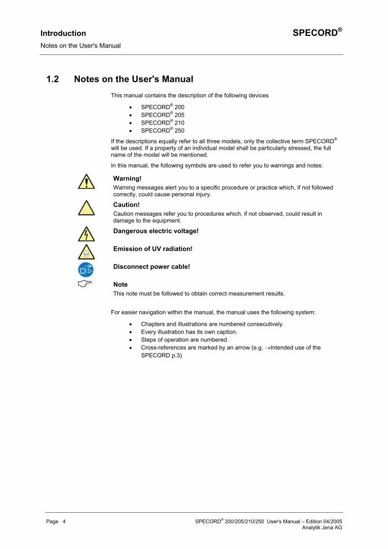
In this manual, the following symbols are used to refer you to warnings and notes:
Warning! Warning messages alert you to a specific procedure or practice which, if not followed correctly, could cause personal injury.
Caution! Caution messages refer you to procedures which, if not observed, could result in damage to the equipment.
Dangerous electric voltage!
Emission of UV radiation!
Disconnect power cable!
Note This note must be followed to obtain correct measurement results.
For easier navigation within the manual, the manual uses the following system:
• Chapters and illustrations are numbered consecutively. • Every illustration has its own caption. • Steps of operation are numbered. • Cross-references are marked by an arrow (e.g. →Intended use of the
SPECORD p.3)
Page 4 SPECORD® 200/205/210/250 User's Manual – Edition 04/2005 Analytik Jena AG

SPECORD® Safety notes Warning labels on SPECORD
2 Safety notes
2.1 Warning labels on SPECORD Observe the warning labels on the SPECORD®!
The following warning labels have been affixed to the lamp housings of the SPECORD®:
Danger! UV radiation! Do not look directly or indirectly via a mirror into the radiation emitted by the UV lamp. The lamp radiation may cause conjunctivitis!
Danger! Hot surface! When lamps are switched on, their covers heat up strongly. If you intend to change the lamps or open the lamp covers, switch the lamps off and allow for a sufficient cool-down time.
2.2 General safety regulations For your personal safety and for a trouble-free operation, carefully read this chapter before starting up the SPECORD®.
Observe all safety notes given in this manual and all messages and notes displayed by the control software on the screen.
In addition, observe the safety notes for system components of other manufacturers (e.g. PC, printer, autosampler) supplied together with the device. In particular, you should also observe the safety notes given on the labels and the information on the use, storage and disposal of reagents, reaction cells and the notes on the package inserts of test kits.
Intended use! The SPECORD®, including original accessories, may only be used for the applications described in this manual. The manufacturer cannot assume any liability for any other application, including that of individual modules or single parts. This also applies to all service or repair work that is not carried out by authorized service personnel. All warranty claims shall be forfeited.
Local safety regulations! Observe the local safety regulations relevant to the operation of the device (e.g. labor-safety regulations, regulations for the prevention of and protection against accidents). References to possible risks given in this manual do not replace the relevant labor-safety regulations that are to be followed.
Personnel! The SPECORD® may only be operated by appropriately qualified and trained personnel. For that, the knowledge of the information provided by this manual is indispensable and taken for granted.
SPECORD® 200/205/210/250 User's Manual – Edition 04/2005 Page 5 Analytik Jena AG
Safety notes SPECORD® General safety regulations
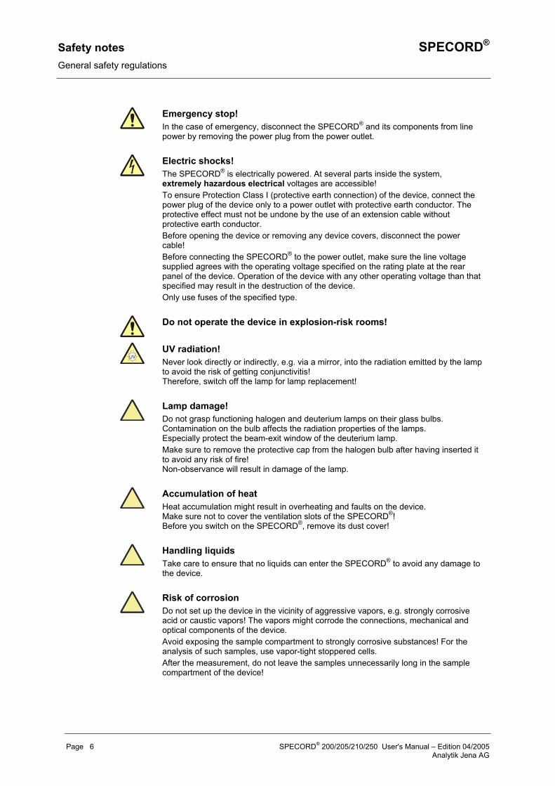
Emergency stop! In the case of emergency, disconnect the SPECORD® and its components from line power by removing the power plug from the power outlet.
Electric shocks! The SPECORD® is electrically powered. At several parts inside the system, extremely hazardous electrical voltages are accessible! To ensure Protection Class I (protective earth connection) of the device, connect the power plug of the device only to a power outlet with protective earth conductor. The protective effect must not be undone by the use of an extension cable without protective earth conductor. Before opening the device or removing any device covers, disconnect the power cable! Before connecting the SPECORD® to the power outlet, make sure the line voltage supplied agrees with the operating voltage specified on the rating plate at the rear panel of the device. Operation of the device with any other operating voltage than that specified may result in the destruction of the device. Only use fuses of the specified type.
Do not operate the device in explosion-risk rooms!
UV radiation! Never look directly or indirectly, e.g. via a mirror, into the radiation emitted by the lamp to avoid the risk of getting conjunctivitis! Therefore, switch off the lamp for lamp replacement!
Lamp damage! Do not grasp functioning halogen and deuterium lamps on their glass bulbs. Contamination on the bulb affects the radiation properties of the lamps. Especially protect the beam-exit window of the deuterium lamp. Make sure to remove the protective cap from the halogen bulb after having inserted it to avoid any risk of fire! Non-observance will result in damage of the lamp.
Accumulation of heat Heat accumulation might result in overheating and faults on the device. Make sure not to cover the ventilation slots of the SPECORD®! Before you switch on the SPECORD®, remove its dust cover!
Handling liquids Take care to ensure that no liquids can enter the SPECORD® to avoid any damage to the device.
Risk of corrosion Do not set up the device in the vicinity of aggressive vapors, e.g. strongly corrosive acid or caustic vapors! The vapors might corrode the connections, mechanical and optical components of the device. Avoid exposing the sample compartment to strongly corrosive substances! For the analysis of such samples, use vapor-tight stoppered cells. After the measurement, do not leave the samples unnecessarily long in the sample compartment of the device!
Page 6 SPECORD® 200/205/210/250 User's Manual – Edition 04/2005 Analytik Jena AG

SPECORD® Safety notes General safety regulations
The SPECORD® was produced and tested in compliance with the following standards and regulations:
• DIN EN 61010-1 (IEC 1010-1) • 73/23/EC • 89/336/EC.
The SPECORD® meets the requirements as per Protection Type IP 20.
SPECORD® 200/205/210/250 User's Manual – Edition 04/2005 Page 7 Analytik Jena AG

SPECORD® Technical data of the spectrophotometers Optical data of SPECORD
3 Technical data of the spectrophotometers
3.1 Optical data of SPECORD
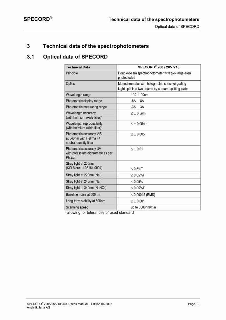
Technical Data SPECORD® 200 / 205 /210
Principle Double-beam spectrophotometer with two large-area photodiodes
Optics Monochromator with holographic concave grating Light split into two beams by a beam-splitting plate
Wavelength range 190-1100nm Photometric display range -8A ... 8A Photometric measuring range -3A ... 3A Wavelength accuracy (with holmium oxide filter)*
≤ ± 0.5nm
Wavelength reproducibility (with holmium oxide filter)*
≤ ± 0.05nm
Photometric accuracy VIS at 546nm with Hellma F4 neutral-density filter
≤ ± 0.005
Photometric accuracy UV with potassium dichromate as per Ph.Eur.
≤ ± 0.01
Stray light at 200nm (KCl Merck 1.08164.0001)
≤ 0.5%T
Stray light at 220nm (NaI) ≤ 0.05%T Stray light at 240nm (NaI) ≤ 0.05% Stray light at 340nm (NaNO2) ≤ 0.05%T Baseline noise at 500nm ≤ 0.00015 (RMS) Long-term stability at 500nm ≤ ± 0.001 Scanning speed up to 6000nm/min
* allowing for tolerances of used standard
SPECORD® 200/205/210/250 User's Manual – Edition 04/2005 Page 9 Analytik Jena AG

Technical data of the spectrophotometers SPECORD® Optical data of SPECORD
Technical Data SPECORD® 250
Optical principle Double-beam spectrophotometer with two large-area photodiodes
Optics Premonochromator and monochromator with holographic concave grating Light split into two beams by a beam-splitting plate
Wavelength range 190-1100nm Photometric display range -8A … 8A Photometric measuring range -4A … 4A Wavelength accuracy (with holmium oxide filter)*
≤ ± 0.5nm
Wavelength reproducibility (with holmium oxide filter)*
≤ ± 0.05nm
Photometric accuracy VIS at 546nm with Hellma F4 neutral-density filter
≤ ± 0.005
Photometric accuracy UV with potassium dichromate as per Ph.Eur.
≤ ± 0.01
Stray light at 200nm (KCl Merck 1.08164.0001)
≤ 0.2%T
Stray light at 220nm (NaI) ≤ 0.008%T Stray light at 240nm (NaI) ≤ 0.008% Stray light at 340nm (NaNO2) ≤ 0.008%T Baseline noise at 500nm ≤ 0.00015 (RMS) Long-term stability at 500nm ≤ ± 0.001 Scanning speed up to 6000nm/min
* allowing for tolerances of used standards
SPECORD® 200 SPECORD® 205 SPECORD® 210 SPECORD® 250 Spectral bandwidth
1; 2; 4 nm variable 1.4 nm 0.5; 1; 2; 4 nm 0.5; 1; 2; 4 nm
Toluene / hexane resolution
> 2.1 > 1.7 > 2.1 > 2.1
Overview 3-1 Technical data of SPECORD® 200
Page 10 SPECORD® 200/205/210/250 User's Manual – Edition 04/2005 Analytik Jena AG

SPECORD® Technical data of the spectrophotometers General technical data of SPECORD
3.2 General technical data of SPECORD
Weight 23.5 kg Footprint (W x D) ca. 1200 x 750 mm2 mit PC Dimensions (W x H x D) 680 x 240 x 620 mm3 Line voltage 230 VAC ±10 % or
115 VAC ±10 % (switchable by service) Line frequency 47 ... 63 Hz Power consumption 200 VA Fuses: Line fuses
230 V~: T 3,15 AH/250V, Type 19181 (Wickmann) 115 V~: T 3,15 AH/250V, Type 19181 (Wickmann)
Radio noise suppression as per EN 55011 Class A Noise immunity as per DIN EN 50082-1 Protection Type IP 20 Data interfaces 2 x RS-232 for accessories
1 x USB port for the connection of an external PC 1 x RS–232 for the connection of an external PC
PC requirements for software: WinASPECT
Pentium processor 133 MHz, 16 MB RAM, Windows 2000 or higher
Overview 3-2 General technical data of SPECORD®
SPECORD® 200/205/210/250 User's Manual – Edition 04/2005 Page 11 Analytik Jena AG

SPECORD® Device description and operating principle Mechanical design of SPECORD
4 Device description and operating principle
4.1 Mechanical design of SPECORD
1
2
3
4
5
6
7
8
9
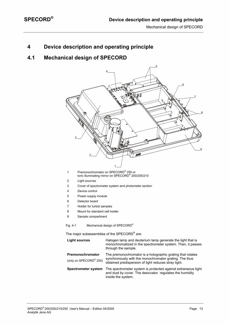
1 Premonochromator on SPECORD® 250 or toric illuminating mirror on SPECORD® 200/205/210
2 Light sources 3 Cover of spectrometer system and photometer section 4 Device control 5 Power supply module 6 Detector board 7 Holder for turbid samples 8 Mount for standard cell holder 9 Sample compartment
Fig. 4-1 Mechanical design of SPECORD®
The major subassemblies of the SPECORD® are:
Light sources Halogen lamp and deuterium lamp generate the light that is monochromatized in the spectrometer system. Then, it passes through the sample.
Premonochromator (only on SPECORD® 250)
The premonochromator is a holographic grating that rotates synchronously with the monochromator grating. The thus obtained predispersion of light reduces stray light.
Spectrometer system The spectrometer system is protected against extraneous light and dust by cover. The desiccator regulates the humidity inside the system.
SPECORD® 200/205/210/250 User's Manual – Edition 04/2005 Page 13 Analytik Jena AG

Device description and operating principle SPECORD® Design of subassemblies
Photometer section This subassembly serves to split the light exiting the monochromator into sample and reference beam. The optical system shapes the beam cross-section in the sample compartment. The photometer section, too, is protected by cover .
Sample compartment The sample compartment contains two pairs of carrier rods for the accommodation of various accessory units. To the support plate, two holders for the accommodation of cells (9) and the detector board are mounted.
Detector board Two photodiodes are used as radiation detectors, which are Peltier temperature-controlled on SPECORD® 200/210/250.
Power supply module
The power supply modules supply the electrical voltage to the electronic system and the fans for the thermoelectric temperature control of the detectors on SPECORD® 200/210.
Device control computer
The device control computer coordinates the interaction of the subassemblies involved in the measurement processes.
4.2 Design of subassemblies
4.2.1 Light sources
SPECORD® 200 / 205 / 210
1 Halogen lamp in protective housing
2 D2E lamp compartment 3 Reflecting mirror 4 Toric illuminating mirror 5 Setscrew for mirror
adjustment
Fig. 4-2 Lamp compartment of SPECORD® 200/205/210
Page 14 SPECORD® 200/205/210/250 User's Manual – Edition 04/2005 Analytik Jena AG
SPECORD® Device description and operating principle Design of subassemblies
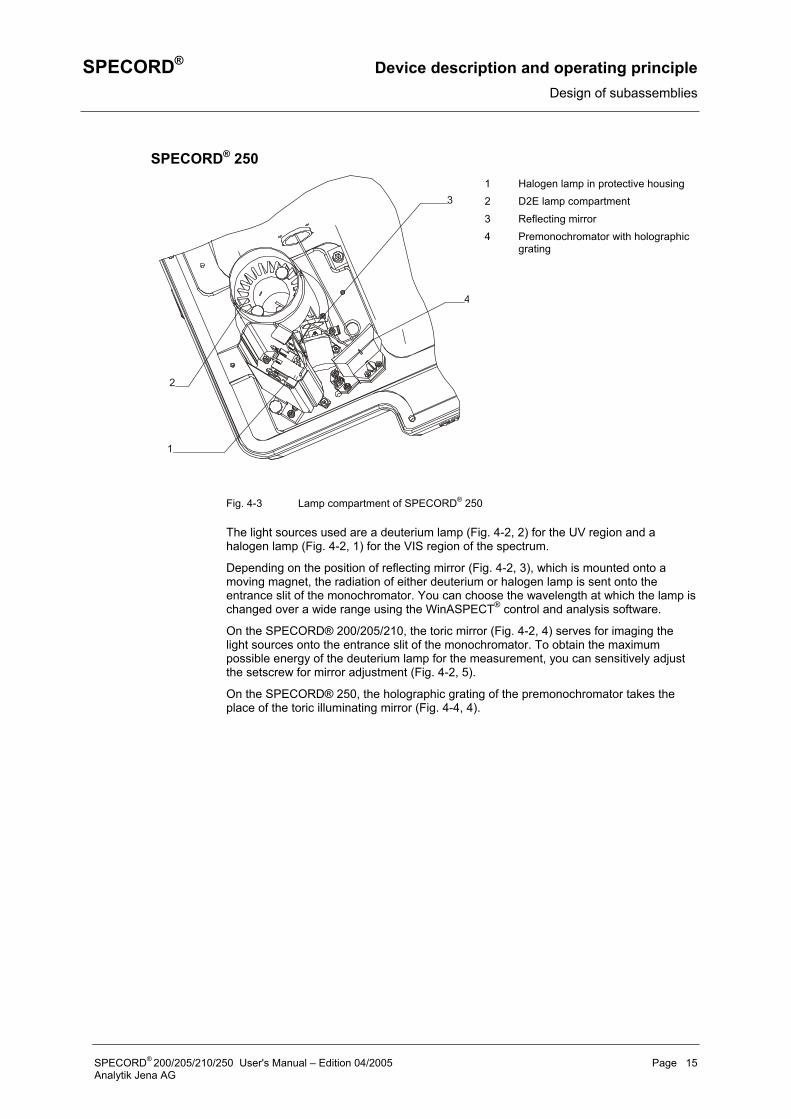
SPECORD® 250
1
2
3
4
1 Halogen lamp in protective housing 2 D2E lamp compartment
3 Reflecting mirror 4 Premonochromator with holographic
grating
Fig. 4-3 Lamp compartment of SPECORD® 250
The light sources used are a deuterium lamp (Fig. 4-2, 2) for the UV region and a halogen lamp (Fig. 4-2, 1) for the VIS region of the spectrum.
Depending on the position of reflecting mirror (Fig. 4-2, 3), which is mounted onto a moving magnet, the radiation of either deuterium or halogen lamp is sent onto the entrance slit of the monochromator. You can choose the wavelength at which the lamp is changed over a wide range using the WinASPECT® control and analysis software.
On the SPECORD® 200/205/210, the toric mirror (Fig. 4-2, 4) serves for imaging the light sources onto the entrance slit of the monochromator. To obtain the maximum possible energy of the deuterium lamp for the measurement, you can sensitively adjust the setscrew for mirror adjustment (Fig. 4-2, 5).
On the SPECORD® 250, the holographic grating of the premonochromator takes the place of the toric illuminating mirror (Fig. 4-4, 4).
SPECORD® 200/205/210/250 User's Manual – Edition 04/2005 Page 15 Analytik Jena AG

Device description and operating principle SPECORD® Design of subassemblies
4.2.2 Spectrometer system and photometer section
Sample compartment
Concave grating
Filter wheelPlane mirror
Beam splitter
Quartz-coatedtoric mirrors
Entrance slit
Exit slit
D E lamp2
Halogen lamp
Swivel mirror
Detector
Detector
Cavity for
Cavity for
turbid samples
turbid samplesCell
Cell
Toric illuminating mirror on SPECORD 200/205/210or premonochromator grating on SPECORD 250
Fig. 4-4 Optical diagram of SPECORD®
The spectrometer system with the optical elements illustrated above – filter wheel, concave grating and slit assembly – works as monochromator.
The filter wheel contains the following filters:
4 color glass filters Used to suppress unwanted radiation in the monochromator.
Holmium filter Standard for the automatic recalibration of wavelengths.
2 blank positions For the passage of non-dispersed light.
Block position Needed for the generation of measured data.
The entrance and exit slits of the spectrometer system are mounted to the slit carrier. Depending on the device model, the slits allow the following spectral slit widths:
SPECORD® 200 1, 2, 4 nm
SPECORD® 205 1.4 nm
SPECORD® 210 / 250 0.5, 1, 2, 4 nm.
The imaging grating disperses the incident light and spreads it out into a spectrum.
Computer-controlled stepper motors drive the filter wheel, the slit carrier and the linear actuator for moving the grating. Because of the little number of moving parts used in the spectrometer system, the SPECORD® ensures a high reliability of its optical parameters.
In the photometer section, the mirror system divides the beam coming from the monochromator into sample and reference beam. The imaging mirrors shape the beam to the cross-sections needed in the sample compartment.
Spectrometer system and photometer section are protected against dust and reagents by a cover. However, corrosive reagents or strongly evaporating liquids should be inserted in the sample compartment only in stoppered cells.
Page 16 SPECORD® 200/205/210/250 User's Manual – Edition 04/2005 Analytik Jena AG
SPECORD® Device description and operating principle Design of subassemblies
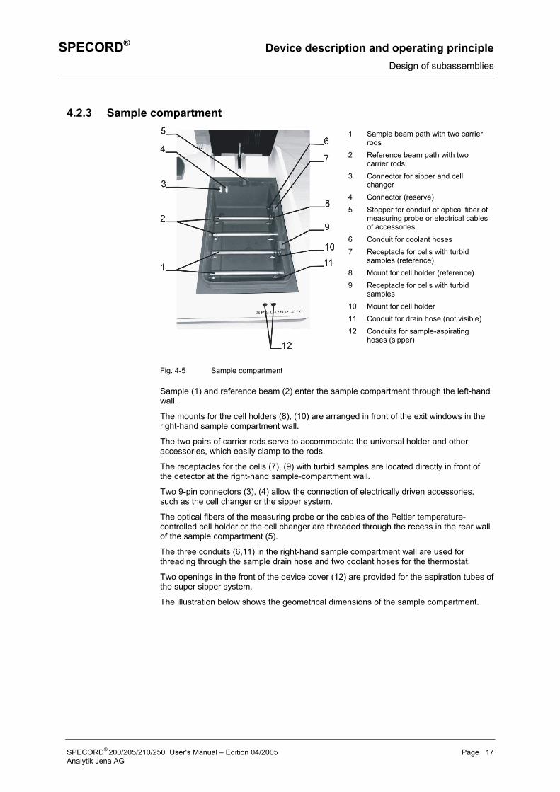
4.2.3 Sample compartment
1 Sample beam path with two carrier rods
2 Reference beam path with two carrier rods
3 Connector for sipper and cell changer
4 Connector (reserve)5 Stopper for conduit of optical fiber of
measuring probe or electrical cables of accessories
6 Conduit for coolant hoses 7 Receptacle for cells with turbid
samples (reference) 8 Mount for cell holder (reference) 9 Receptacle for cells with turbid
samples10 Mount for cell holder11 Conduit for drain hose (not visible)12 Conduits for sample-aspirating
hoses (sipper)
Fig. 4-5 Sample compartment
Sample (1) and reference beam (2) enter the sample compartment through the left-hand wall.
The mounts for the cell holders (8), (10) are arranged in front of the exit windows in the right-hand sample compartment wall.
The two pairs of carrier rods serve to accommodate the universal holder and other accessories, which easily clamp to the rods.
The receptacles for the cells (7), (9) with turbid samples are located directly in front of the detector at the right-hand sample-compartment wall.
Two 9-pin connectors (3), (4) allow the connection of electrically driven accessories, such as the cell changer or the sipper system.
The optical fibers of the measuring probe or the cables of the Peltier temperature-controlled cell holder or the cell changer are threaded through the recess in the rear wall of the sample compartment (5).
The three conduits (6,11) in the right-hand sample compartment wall are used for threading through the sample drain hose and two coolant hoses for the thermostat.
Two openings in the front of the device cover (12) are provided for the aspiration tubes of the super sipper system.
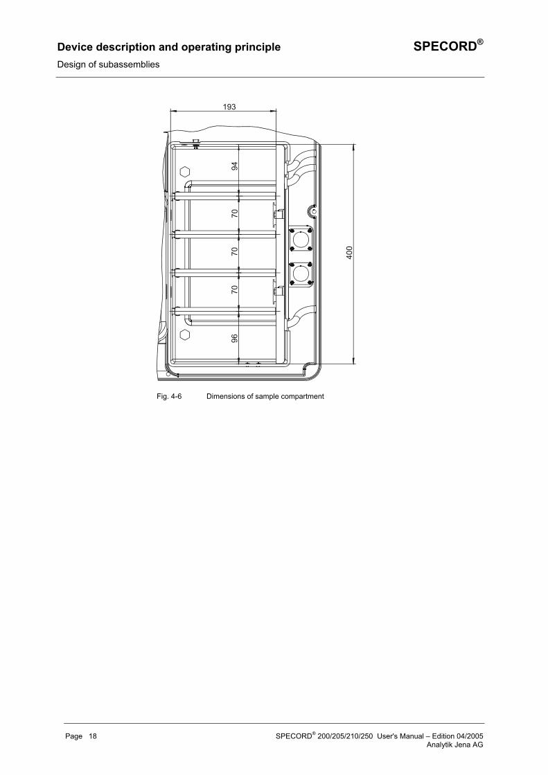
The illustration below shows the geometrical dimensions of the sample compartment.
SPECORD® 200/205/210/250 User's Manual – Edition 04/2005 Page 17 Analytik Jena AG
Device description and operating principle SPECORD® Design of subassemblies
400
193
9470
7070
96
Fig. 4-6 Dimensions of sample compartment
Page 18 SPECORD® 200/205/210/250 User's Manual – Edition 04/2005 Analytik Jena AG
SPECORD® Installation and transport conditions Design of subassemblies
5 Installation and transport conditions
Installation conditions
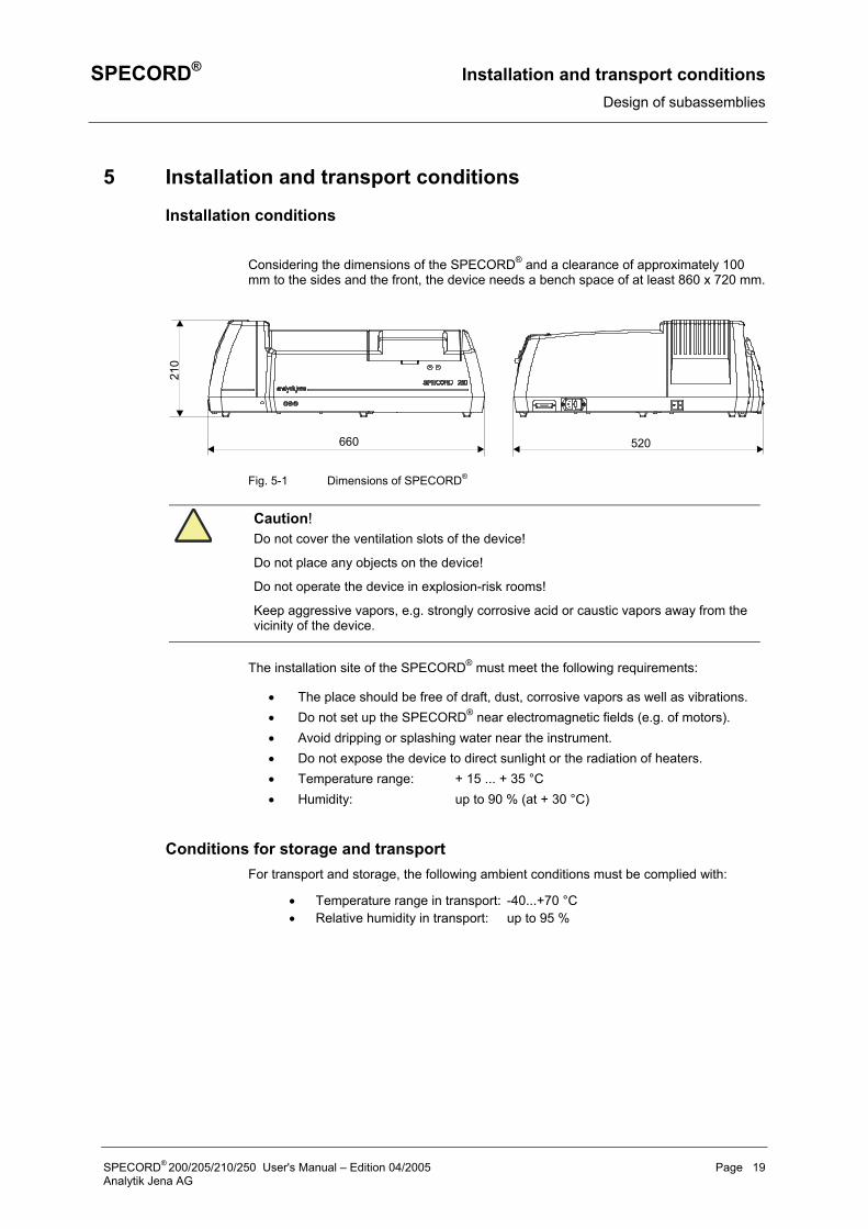
Considering the dimensions of the SPECORD® and a clearance of approximately 100 mm to the sides and the front, the device needs a bench space of at least 860 x 720 mm.
210
660 520
Fig. 5-1 Dimensions of SPECORD®
Caution! Do not cover the ventilation slots of the device!
Do not place any objects on the device!
Do not operate the device in explosion-risk rooms!
Keep aggressive vapors, e.g. strongly corrosive acid or caustic vapors away from the vicinity of the device.
The installation site of the SPECORD® must meet the following requirements:
• The place should be free of draft, dust, corrosive vapors as well as vibrations. • Do not set up the SPECORD® near electromagnetic fields (e.g. of motors). • Avoid dripping or splashing water near the instrument. • Do not expose the device to direct sunlight or the radiation of heaters. • Temperature range: + 15 ... + 35 °C • Humidity: up to 90 % (at + 30 °C)
Conditions for storage and transport For transport and storage, the following ambient conditions must be complied with:
• Temperature range in transport: -40...+70 °C • Relative humidity in transport: up to 95 %
SPECORD® 200/205/210/250 User's Manual – Edition 04/2005 Page 19 Analytik Jena AG

SPECORD® Installation and start-up Connectors and display elements
6 Installation and start-up
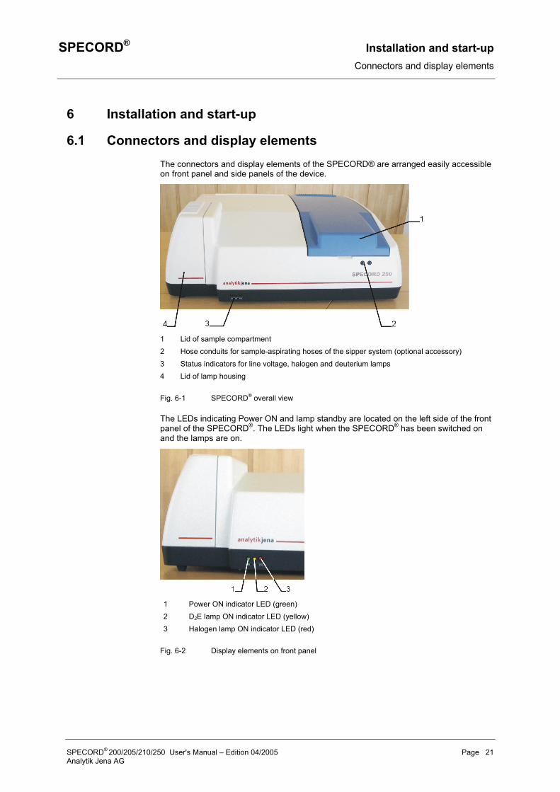
6.1 Connectors and display elements The connectors and display elements of the SPECORD® are arranged easily accessible on front panel and side panels of the device.
1 Lid of sample compartment 2 Hose conduits for sample-aspirating hoses of the sipper system (optional accessory) 3 Status indicators for line voltage, halogen and deuterium lamps 4 Lid of lamp housing
Fig. 6-1 SPECORD® overall view
The LEDs indicating Power ON and lamp standby are located on the left side of the front panel of the SPECORD®. The LEDs light when the SPECORD® has been switched on and the lamps are on.
1 Power ON indicator LED (green) 2 D2E lamp ON indicator LED (yellow) 3 Halogen lamp ON indicator LED (red)
Fig. 6-2 Display elements on front panel
SPECORD® 200/205/210/250 User's Manual – Edition 04/2005 Page 21 Analytik Jena AG
Installation and start-up SPECORD® Connectors and display elements
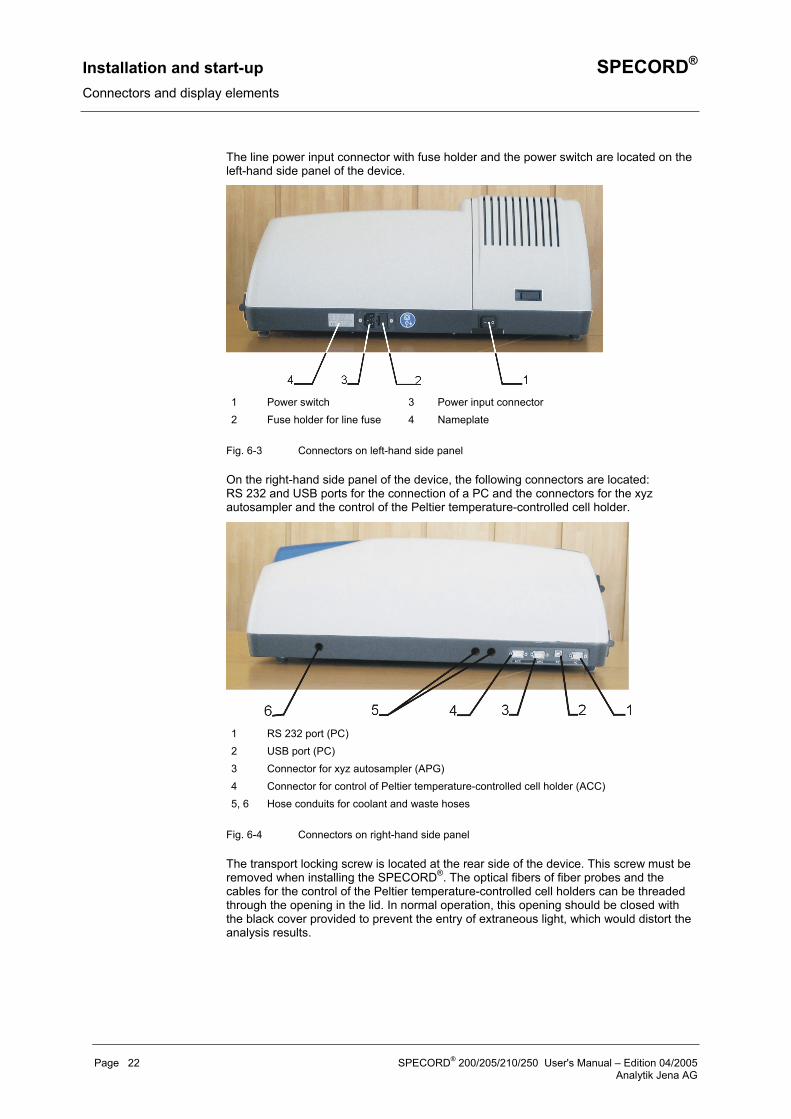
The line power input connector with fuse holder and the power switch are located on the left-hand side panel of the device.
1 Power switch 3 Power input connector 2 Fuse holder for line fuse 4 Nameplate
Fig. 6-3 Connectors on left-hand side panel
On the right-hand side panel of the device, the following connectors are located: RS 232 and USB ports for the connection of a PC and the connectors for the xyz autosampler and the control of the Peltier temperature-controlled cell holder.
1 RS 232 port (PC) 2 USB port (PC) 3 Connector for xyz autosampler (APG) 4 Connector for control of Peltier temperature-controlled cell holder (ACC) 5, 6 Hose conduits for coolant and waste hoses
Fig. 6-4 Connectors on right-hand side panel
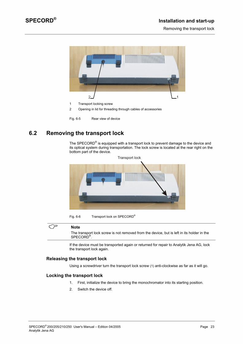
The transport locking screw is located at the rear side of the device. This screw must be removed when installing the SPECORD®. The optical fibers of fiber probes and the cables for the control of the Peltier temperature-controlled cell holders can be threaded through the opening in the lid. In normal operation, this opening should be closed with the black cover provided to prevent the entry of extraneous light, which would distort the analysis results.
Page 22 SPECORD® 200/205/210/250 User's Manual – Edition 04/2005 Analytik Jena AG
SPECORD® Installation and start-up Removing the transport lock
1 Transport locking screw 2 Opening in lid for threading through cables of accessories
Fig. 6-5 Rear view of device
6.2 Removing the transport lock The SPECORD® is equipped with a transport lock to prevent damage to the device and its optical system during transportation. The lock screw is located at the rear right on the bottom part of the device.
Transport lock
Fig. 6-6 Transport lock on SPECORD®
Note The transport lock screw is not removed from the device, but is left in its holder in the SPECORD®.
If the device must be transported again or returned for repair to Analytik Jena AG, lock the transport lock again.
Releasing the transport lock Using a screwdriver turn the transport lock screw (1) anti-clockwise as far as it will go.
Locking the transport lock 1. First, initialize the device to bring the monochromator into its starting position.
2. Switch the device off.
SPECORD® 200/205/210/250 User's Manual – Edition 04/2005 Page 23 Analytik Jena AG
Installation and start-up SPECORD® Connecting the SPECORD
3. Using a screwdriver, turn the transport lock screw (1) clockwise as far as it will go.
6.3 Connecting the SPECORD
Observe correct position of device! Move the SPECORD® only in upright position (observe label on transport case). Do not turn the device upside down. Release transport lock! Loosen the transport lock screw located on the rear left of the SPECORD®.
Electric shock Before connecting the SPECORD® and the PC to line power, make sure the available line voltage agrees with the operating voltage specified on the type labels. Operation of the devices on line voltages other than the specified operating voltage may result in their destruction.
Standard equipment The standard equipment of the SPECORD® includes the following items:
• 2 cell holders • Installation CD-ROM of WinASPECT® basic module • Spare halogen lamp • Deuterium lamp • Power cable • PC – SPECORD® connecting cable • Spare fuses 5 x 20 T 3.15 A L • User's Manuals for the SPECORD®, the accessories and the WinASPECT®
control and analysis software.
Connecting SPECORD® and PC 1. Remove the device from its transport packaging and remove the plastic cover. Wait
until the device has adjusted to the ambient temperature.
2. Remove the foamed plastic packaging from the SPECORD® sample compartment. The packaging contains the items included in the standard equipment (see above) and the installation disks for the WinASPECT® optional module you ordered.
3. Install the software on the PC (→ Refer to WinASPECT® User's Manual).
4. Insert the deuterium lamp following the instructions given in Section 8.3 Changing lamps p. 32.
5. Connect the SPECORD® (→ see 6.1 Connectors and display elements p. 21) to the PC (free COM port) using the supplied connecting cable.
6. Connect one power cable each to the SPECORD® and the PC. Connect the power cables of the SPECORD® and the PC to power outlets that are connected to the same phase of the line power supply (multiple socket outlet, if possible).
Page 24 SPECORD® 200/205/210/250 User's Manual – Edition 04/2005 Analytik Jena AG
SPECORD® Installation and start-up Start-up
Note When required, align the lamps following the instructions given in Section 8.3 Changing lamps, p. 32 after start-up.
6.4 Start-up
Do not cover ventilation slots of the device! Take care to ensure that the ventilation slots on the top and on the right and left bottom of the SPECORD® are not covered. Do not place any objects in front of the openings. The suction intakes for the two fans on the bottom of the device must be kept free.
1. Start WinASPECT® software by a click on the program icon on the Windows desktop or by clicking the Start button on the taskbar: Start / Programs / WinASPECT / WinASPECT.
Fig. 6-7 Program symbol of WinASPECT®
2. Using the power switch on the left panel of the device, switch the SPECORD® on (→ Refer to Fig. 6-3 Connectors on left-hand side panel, p. 22).
3. The green Power ON LED on the front panel of the device lights. (→ Refer to Fig. 6-2 Display elements on front panel, p. 21).
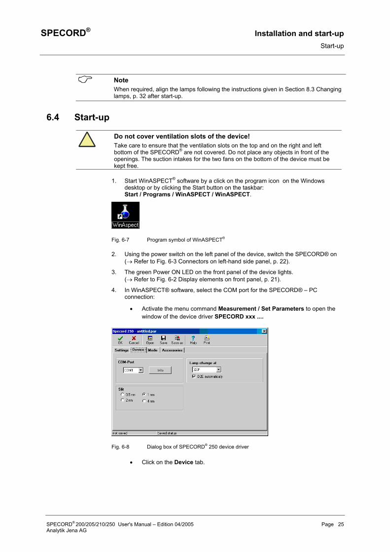
4. In WinASPECT® software, select the COM port for the SPECORD® – PC connection:
• Activate the menu command Measurement / Set Parameters to open the window of the device driver SPECORD xxx ....
Fig. 6-8 Dialog box of SPECORD® 250 device driver
• Click on the Device tab.
SPECORD® 200/205/210/250 User's Manual – Edition 04/2005 Page 25 Analytik Jena AG
Installation and start-up SPECORD® Switching the device off
• From the COM Port list box, select the COM port of your PC, to which the SPECORD® is connected.
• Click on [OK] to close the device driver window.
Note The selected COM port will be saved and remain set until you change the COM port setting. Thus, you need not select it after every restart of the device.
5. Initialize the device: Establish communication between SPECORD® and PC using the menu command Measurement / Initialize Device.
The SPECORD® is now ready for taking measurements.
Note Please note that the SPECORD® reaches thermal stability only after a warm-up time of one hour. Therefore, you should not start precision measurements unless the device has warmed up.
6.5 Switching the device off
6.5.1 Switching the deuterium lamp off If you have worked with the deuterium lamp and you are sure that you do not need it any longer this day, you can switch it off by software control following this procedure:
1. In WinASPECT®, activate the device driver with menu command Measurement / Set Parameters.
2. Activate the Device tab.
3. In the Lamp change at field, deactivate the D2E automatically function.
4. Close the device driver window by a click on [OK].
5. Reinitialize the device using the following menu command: Measurement / Initialize Device.
6. A query appears on the screen asking you if you want to switch on the UV lamp. Click the [No] button.
The UV lamp goes out.
6.5.2 Switching the SPECORD off We recommend that the SPECORD® be powered down by software control after you have finished taking measurements:
1. Exit WinASPECT® using menu command File / Exit.
2. Then, shut down the computer.
3. Finally, switch the SPECORD® off with the power switch.
Note If you have finished the measurements on the SPECORD® but want to analyze the obtained results on the PC, you can also switch off the SPECORD® without shutting down the computer before.
Page 26 SPECORD® 200/205/210/250 User's Manual – Edition 04/2005 Analytik Jena AG
SPECORD® Accessories Standard cell holders
7 Accessories
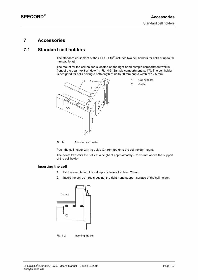
7.1 Standard cell holders The standard equipment of the SPECORD® includes two cell holders for cells of up to 50 mm pathlength.
The mount for the cell holder is located on the right-hand sample compartment wall in front of the beam-exit window (→ Fig. 4-5 Sample compartment, p. 17). The cell holder is designed for cells having a pathlength of up to 50 mm and a width of 12.5 mm.
1 Cell support 2 Guide
Fig. 7-1 Standard cell holder
Push the cell holder with its guide (2) from top onto the cell-holder mount.
The beam transmits the cells at a height of approximately 5 to 15 mm above the support of the cell holder.
Inserting the cell 1. Fill the sample into the cell up to a level of at least 20 mm.
2. Insert the cell so it rests against the right-hand support surface of the cell holder.
Correct
Fig. 7-2 Inserting the cell
SPECORD® 200/205/210/250 User's Manual – Edition 04/2005 Page 27 Analytik Jena AG
Accessories SPECORD® Receptacle for cells with turbid samples
Note In absorbance measurements, the pathlength is one of the crucial factors. Therefore, it is important to insert all samples (samples and references) in the same location and position. In this way, you can avoid measurement errors caused by angular differences and parallel offset of the beam.
7.2 Receptacle for cells with turbid samples In the measurement of strongly turbid samples, a considerable portion of the radiation does not exit the sample cell straightly, but is scattered within a solid angle. For photometrically accurate measurements it is necessary that the detector capture the total scattered radiation. For this purpose, the sample and the reference substance must be arranged as close to the detector as possible.
Therefore, the receptacles for the cells with scattering samples are located in the right-hand sample-compartment wall of the SPECORD® in front of the photodiode detectors (Fig. 4-5, 7 and 9 p.17). The receptacles can accommodate standard cells of 10 mm pathlength.
1. Remove the foamed-plastic caps covering the cell receptacles and insert the cells for the analysis.
2. After the measurement is finished, make sure to cover the cell receptacles again with the foamed-plastic caps. If you fail to do so, extraneous light might be incident on the detector and distort the results of the measurements.
Page 28 SPECORD® 200/205/210/250 User's Manual – Edition 04/2005 Analytik Jena AG
SPECORD® Accessories Additional accessories
7.3 Additional accessories Optionally the following accessories are available for the SPECORD:
• Universal cell holder • Thermostatted cell holder, water-cooled • Thermostatted cell holder; Peltier-controlled • Adjustable cell holder for micro, submicro or HPLC cells • 6-cell changer, water-cooled • 6-cell changer, Peltier-controlled • Holder for cylindrical cells of up to 100 mm • Holder for round cells • Holder for solid samples • 11° ... 60° variable Angle Reflectance Accessory • Absolute Reflectance Accessory • Universal sipper system with flow cell and peristaltic pump • XYZ autosampler • Fiber coupling with measuring probes • 75-mm integrating sphere for transmission and diffuse reflectance • PTC 100, Peltier temperature-controlled cell holder • PTC 600, Peltier temperature-controlled 6-cell changer • SMA fiber connector • 8-cell changer (non-thermostatted, water-thermostatted or Peltier thermostatted) • Combination of 2 x 8-cell changers
SPECORD® 200/205/210/250 User's Manual – Edition 04/2005 Page 29 Analytik Jena AG

SPECORD® Care, maintenance, lamp change Care and maintenance
8 Care, maintenance, lamp change
8.1 Care and maintenance The SPECORD® is largely free of maintenance.
To ensure your laboratory certification with device validation, Analytik Jena AG offers you a service/maintenance agreement.
User care and maintenance is limited to the following operations:
• Cleaning of sample compartment and device casing • Lamp change • Change of line fuses • Change of desiccator
You should only use spares from Analytik Jena AG.
You can order consumables and wear parts by phone from our Service Department:
Hotline No.: + 49 3641-77-7407
In the case of malfunction of the device, please contact our Service Department. For the address, refer to the → inside cover page.
8.2 Cleaning Avoid keeping filled cells unnecessarily long in the sample compartment to prevent the spectrometer from being affected by any solvent vapors.
Wipe off spilt samples in the sample compartment or on accessory units instantly with cleaning tissue.
Wipe off contamination on the instrument with a soft, clean cloth slightly moistened with a commercially available, neutral detergent.
SPECORD® 200/205/210/250 User's Manual – Edition 04/2005 Page 31 Analytik Jena AG
Care, maintenance, lamp change SPECORD® Changing lamps
8.3 Changing lamps
8.3.1 Note on the service life of lamps The service life of lamps is:
• Halogen lamp: > 500 h (at 5.0 V operating voltage) • Deuterium lamp: > 1000 h
The service life of the lamps is reduced, if the SPECORD® is frequently switched on and off. This particularly applies to the deuterium lamp, because of the relatively high ignition voltage required.
The following rule applies as criterion for the service life of the deuterium lamp: With one daily ON/OFF switching operation, its radiation intensity is allowed to decrease to 50% after 1000 hours.
The deuterium lamp must be changed, if its heating coil has burnt out, its energy is insufficient or the operating hours counter indicates 2000 h.
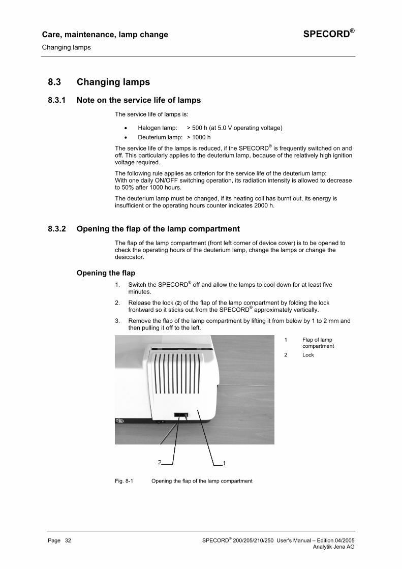
8.3.2 Opening the flap of the lamp compartment The flap of the lamp compartment (front left corner of device cover) is to be opened to check the operating hours of the deuterium lamp, change the lamps or change the desiccator.
Opening the flap 1. Switch the SPECORD® off and allow the lamps to cool down for at least five
minutes.
2. Release the lock (2) of the flap of the lamp compartment by folding the lock frontward so it sticks out from the SPECORD® approximately vertically.
3. Remove the flap of the lamp compartment by lifting it from below by 1 to 2 mm and then pulling it off to the left.
1 Flap of lamp compartment
2 Lock
Fig. 8-1 Opening the flap of the lamp compartment
Page 32 SPECORD® 200/205/210/250 User's Manual – Edition 04/2005 Analytik Jena AG
SPECORD® Care, maintenance, lamp change Changing lamps
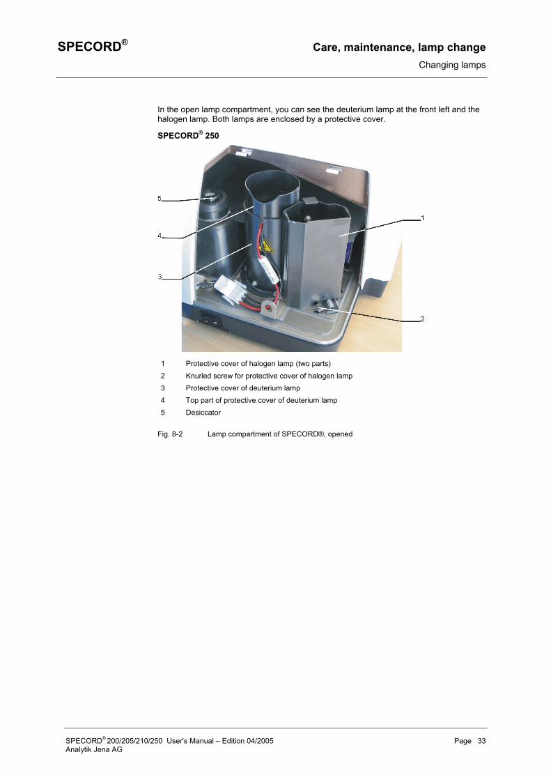
In the open lamp compartment, you can see the deuterium lamp at the front left and the halogen lamp. Both lamps are enclosed by a protective cover.
SPECORD® 250
1 Protective cover of halogen lamp (two parts) 2 Knurled screw for protective cover of halogen lamp 3 Protective cover of deuterium lamp 4 Top part of protective cover of deuterium lamp 5 Desiccator
Fig. 8-2 Lamp compartment of SPECORD®, opened
SPECORD® 200/205/210/250 User's Manual – Edition 04/2005 Page 33 Analytik Jena AG
Care, maintenance, lamp change SPECORD® Changing lamps
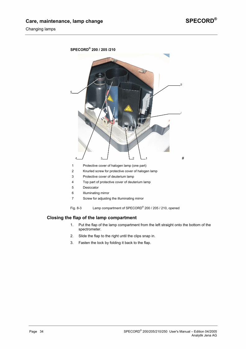
SPECORD® 200 / 205 /210
#
1 Protective cover of halogen lamp (one part) 2 Knurled screw for protective cover of halogen lamp 3 Protective cover of deuterium lamp 4 Top part of protective cover of deuterium lamp 5 Desiccator 6 Illuminating mirror 7 Screw for adjusting the illuminating mirror
Fig. 8-3 Lamp compartment of SPECORD® 200 / 205 / 210, opened
Closing the flap of the lamp compartment 1. Put the flap of the lamp compartment from the left straight onto the bottom of the
spectrometer.
2. Slide the flap to the right until the clips snap in.
3. Fasten the lock by folding it back to the flap.
Page 34 SPECORD® 200/205/210/250 User's Manual – Edition 04/2005 Analytik Jena AG
SPECORD® Care, maintenance, lamp change Changing lamps
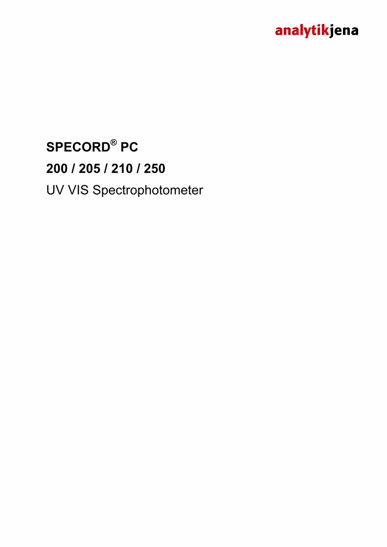
8.3.3 Changing the deuterium lamp
Risk of electric shock! Before changing the deuterium lamp, make sure to switch the device off with the power switch.
Caution: Risk of burns! Allow the deuterium lamp to cool down to avoid the risk of burns!
Emitted UV radiation! Never look directly or indirectly, e.g. via a mirror, into the radiation emitted by the lamp to avoid the risk of getting conjunctivitis!
Dirt on beam exit window! Do not touch the glass bulb of the new deuterium lamp. Particularly avoid contamination on the quartz glass beam exit window! If you touched the glass bulb with your fingers, wipe the fingerprints off with a clean, lintfree cloth and pure alcohol. The performance of the lamp will deteriorate by contamination.
After you have removed the flap of the lamp compartment, the lamps are visible in their protective covers (Fig. 8-2 and Fig. 8-3).
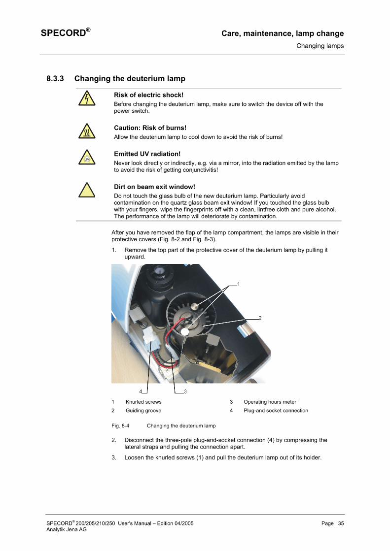
1. Remove the top part of the protective cover of the deuterium lamp by pulling it upward.
1 Knurled screws 3 Operating hours meter 2 Guiding groove 4 Plug-and socket connection
Fig. 8-4 Changing the deuterium lamp
2. Disconnect the three-pole plug-and-socket connection (4) by compressing the lateral straps and pulling the connection apart.
3. Loosen the knurled screws (1) and pull the deuterium lamp out of its holder.
SPECORD® 200/205/210/250 User's Manual – Edition 04/2005 Page 35 Analytik Jena AG
Care, maintenance, lamp change SPECORD® Changing lamps
4. Remove the new deuterium lamp from its packaging and insert it in the lamp holder taking care that the locating pin of the lamp holder fits into groove (2) of the lamp base.
5. Screw down the deuterium lamp by means of both knurled screws (1). Reconnect the lamp connector (4).
6. Finally, reattach the top part of the protective cover of the lamp acc. to Fig. 8-2 or Fig. 8-3.
Fine alignment of deuterium lamp of SPECORD® 200 / 205 / 210
Fine alignment on the SPECORD® 250 by the user is not planned! On this device, the premonochromator is mounted in place of the toric illuminating mirror. The premonochromator operates synchronously with the main monochromator. Improper attempts of alignment may result in severe alignment faults! If the energy of the deuterium lamp should be insufficient even after lamp replacement, contact our Technical Service!
Despite stringent manufacturing tolerances of the deuterium lamps, it may be necessary to realign the lamp after lamp change to ensure that maximum intensity of the lamp is incident on the entrance slit of the monochromator. For this purpose, you can slightly move the illuminating mirror by means of setscrew (Fig. 8-3, 7).
Caution! Do not remove the protective cover of the halogen lamp during the aligment! The thus produced stray light will result in alignment errors!
1. Switch the SPECORD® on and initialize it. To this end, start WinASPECT® and activate the following menu command: Measurement / Initialize Device.
2. Set up a parameter record containing the following parameters:
Wavelength 230 nm Integration time 0.5 s Display Energy Cycle Automatic, 200x
3. Start the measurement with the sample compartment kept closed. Keep the flap of the lamp compartment open.
4. Sensitively turn the setscrew (11) in both directions until the detected energy reaches its maximum.
5. This adjustment also influences the alignment of the deuterium lamp. However, the variation is comparatively small and normally negligible.
6. Finally, close the flap of the lamp compartment.
Note Please note that the deuterium lamp needs a warm-up of one hour after ignition to reach full thermal stability.
Page 36 SPECORD® 200/205/210/250 User's Manual – Edition 04/2005 Analytik Jena AG
SPECORD® Care, maintenance, lamp change Changing lamps
8.3.4 Changing the halogen lamp
Electric shock! Before changing the halogen lamp, make sure to switch the device off with the power switch.
Caution: Risk of burns! Allow the halogen lamp to cool down to avoid the risk of burns!
Emitted radiation! Never look into the lighting lamp as the radiation may cause eye injury!
Caution! Do not touch the glass bulb of the lamp to avoid any contamination affecting its performance!
Open the lamp-compartment flap. The protective cover of the halogen lamp is visible.
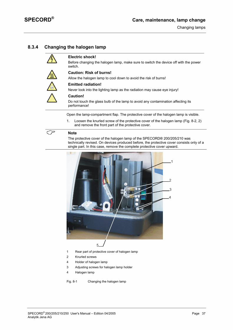
1. Loosen the knurled screw of the protective cover of the halogen lamp (Fig. 8-2, 2) and remove the front part of the protective cover.
Note The protective cover of the halogen lamp of the SPECORD® 200/205/210 was technically revised. On devices produced before, the protective cover consists only of a single part. In this case, remove the complete protective cover upward.
1 Rear part of protective cover of halogen lamp 2 Knurled screws 4 Holder of halogen lamp 3 Adjusting screws for halogen lamp holder 4 Halogen lamp
Fig. 8-1 Changing the halogen lamp
SPECORD® 200/205/210/250 User's Manual – Edition 04/2005 Page 37 Analytik Jena AG
Care, maintenance, lamp change SPECORD® Changing lamps
2. Loosen the two clamping screws (2).
3. Pull the defective halogen lamp (5) out of its holder (3).
4. Remove the new halogen lamp from its packaging, but keep the protective sheath attached.
5. Insert the new halogen lamp taking care to ensure that the notch at its base encloses the pin in the bottom part of the holder.
6. Reattach the protective cover of the halogen lamp and refasten it.
Fine alignment of halogen lamp Check the alignment of the halogen lamp.
1. For this purpose, switch the SPECORD® on and initialize it. To this end, start WinASPECT® and activate the following menu command: Measurement / Initialize Device.
2. Exit WinASPECT® to run the Service Check routine and activate the Service Check routine as follows: Click on the [Start] button of the Windows taskbar. In the Programs folder, click on the WinASPECT folder. There, click on the Service xxx command. This will bring up the SPECORD xxx - Service Check dialog box.
3. Click on the [Zeroth Order] button and choose the halogen lamp (HL – Lamp).
4. View the image of the sample beam in the sample compartment by holding a white sheet of paper in the plane where normally the cell is placed. There, a 7 – 8 mm high and 1 – 2 mm wide light spot should be visible that is evenly illuminated from top to bottom.
5. If you find that the light spot on the sheet of paper is badly uneven, verify that the halogen lamp is correctly seated.
6. Perform wavelength correction and check the zeroth order and automatic adjustment of gain stages.
7. If you are not satisfied with the alignment of the halogen lamp, loosen the fastening screws (Fig. 8-1, 3) and move the lamp sensitively while running an energy measurement as described above for the fine alignment of the deuterium lamp on the SPECORD® 200/205/210. For that, the ideal wavelength is 500 nm.
Note Please note that the halogen lamp needs a warm-up of about one hour after switch on to reach full thermal stability.
Page 38 SPECORD® 200/205/210/250 User's Manual – Edition 04/2005 Analytik Jena AG

SPECORD® Care, maintenance, lamp change Changing the desiccator
8.4 Changing the desiccator
Danger! Hot surface! Before replacing the desiccator, switch off the SPECORD®. Allow for a sufficient cool-down time of the lamps. Touching the hot lamp surfaces housings may cause burns!
The desiccator protects the optical system of the SPECORD® against too high air humidity. The desiccator is accessible, when the lamp compartment has been opened (→ Refer to Fig. 8-2, 5, p.33)
Especially in tropical countries, the adsorption capacity of the desiccator should be checked regularly. The adsorption capacity of the desiccator is exhausted, if the color of the indicator paper in the inspection window has changed from blue to pink-yellow.
For changing the desiccator, follow this procedure:
1. Open the flap of the lamp compartment by folding the lock frontward so it sticks out vertically. Lift the flap from below by 1 to 2 mm and then pull it off to the left.
2. Using a flat tool, such as an appropriate coin, unscrew the desiccator from its holder.
3. Remove the new desiccator from the packaging and screw it into the holder.
4. Finally, close the flap of the lamp compartment.
Used up desiccators can be reused after heating them up for five hours in a drying oven. New desiccators are available from our Service Department (→ for the address, refer to the inside cover page).
8.5 Changing fuses If the line fuses are defective, you can change them yourself.
Risk of electric shock! Before changing the fuses, make sure to switch the SPECORD® off with the power switch and disconnect the power cable from the power input connector of the device.
1. Remove the power cable from the SPECORD®.
2. Open the fuse holder (→ Refer to Fig. 6-3, p. 22) by pulling on its lid.
3. Replace the defective line fuses. Make sure to use only the following fuse types:
• T 3.15 H/250 V, Type 19181 for line voltages of 150 VAC and 230 VAC.
4. Close the fuse holder again.
5. Reconnect the power cable to the power input connector of the SPECORD® and the power outlet.
6. Switch the SPECORD® on again.
SPECORD® 200/205/210/250 User's Manual – Edition 04/2005 Page 39 Analytik Jena AG


SPECORD® Disposal
9 Disposal
The owner/operator of the SPECORD® must ensure to dispose of the waste material (samples) cropping up in the analyses in accordance with the relevant legal and local regulations.
When the service life of the device is over, dispose of the device with its electronic components as electronic scrap observing the relevant regulations.
You can also return the SPECORD® to Analytik Jena AG for disposal. Please contact our Technical Service.
SPECORD® 200/205/210/250 User's Manual – Edition 04/2005 Page 41 Analytik Jena AG

SPECORD® Index to Illustrations
10 Index to Illustrations Fig. 4-1 Mechanical design of SPECORD® ................................................................ 13 Fig. 4-2 Lamp compartment of SPECORD® 200/205/210 .......................................... 14 Fig. 4-3 Lamp compartment of SPECORD® 250 ........................................................ 15 Fig. 4-4 ..................................................................... 16 Optical diagram of SPECORD®
Fig. 4-5 Sample compartment .................................................................................... 17 Fig. 4-6 Dimensions of sample compartment ............................................................. 18 Fig. 5-1 ........................................................................... 19 Dimensions of SPECORD®
Fig. 6-1 SPECORD® overall view ............................................................................... 21 Fig. 6-2 Display elements on front panel .................................................................... 21 Fig. 6-3 Connectors on left-hand side panel............................................................... 22 Fig. 6-4 Connectors on right-hand side panel............................................................. 22 Fig. 6-5 Rear view of device ....................................................................................... 23 Fig. 6-6 ...................................................................... 23 Transport lock on SPECORD®
Fig. 6-7 Program symbol of WinASPECT® ................................................................. 25 Fig. 6-8 Dialog box of SPECORD® 250 device driver................................................. 25 Fig. 7-1 Standard cell holder ...................................................................................... 27 Fig. 7-2 Inserting the cell ............................................................................................ 27 Fig. 8-1 Opening the flap of the lamp compartment ................................................... 32 Fig. 8-2 Lamp compartment of SPECORD®, opened ................................................ 33 Fig. 8-3 Lamp compartment of SPECORD® 200 / 205 / 210, opened ........................ 34 Fig. 8-4 Changing the deuterium lamp ....................................................................... 35
11 Index to Overviews Overview 3-1 Technical data of SPECORD® 200 ...................................................... 10 Overview 3-2 ................................................. 11 General technical data of SPECORD®
SPECORD® 200/205/210/250 User's Manual – Edition 04/2005 Page 43 Analytik Jena AG