Embed Size (px)
Citation preview
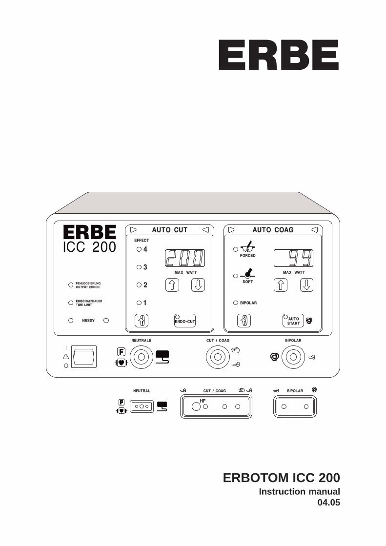
ERBOTOM ICC 200Instruction manual
04.05
ERBE

Instruction manual04.05
ERBOTOM ICC 200 V 2.X10128-002, 10128-009, 10128-303, 10128-027, 10128-403
ERBOTOM ICC 200 E V 2.X10128-010, 10128-015, 10128-304,10128-028
ERBOTOM ICC 200 EA V 2.X10128-023, 10128-036, 10128-305, 10128-058, 10128-400
All rights to this instruction manual, particularly the right to reproduction, distribution and translation, are reserved.No part of this instruction manual may be reproduced in any form (including photocopying, microfilm or othermeans), or processed, reproduced or distributed by means of electronic systems without prior written permissionfrom ERBE ELEKTROMEDIZIN GmbH.The information contained in this instruction manual may be revised or extended without prior notice and representsno obligation on the part of ERBE ELEKTROMEDIZIN GmbH.
© ERBE ELEKTROMEDIZIN GmbH, Tübingen 2005
Printed by: ERBE ELEKTROMEDIZIN, Tübingen Instruction manual no. 80104-401
EN ISO 13485 EN ISO 9001
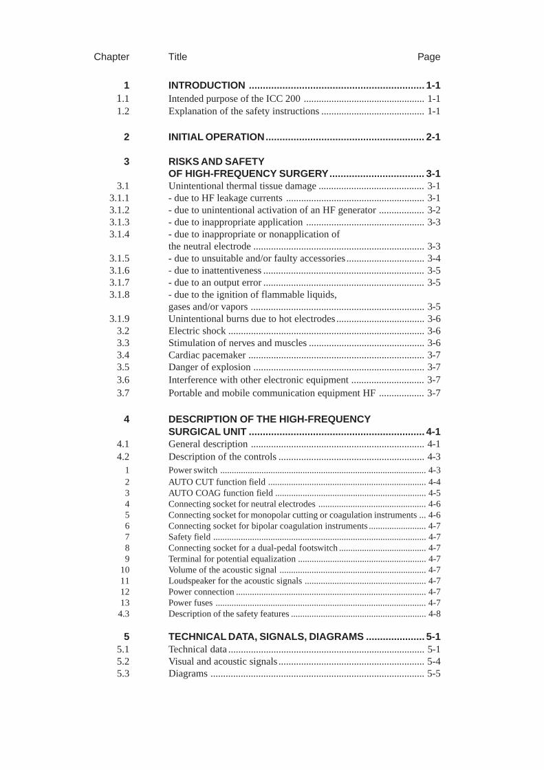
Chapter Title Page
1 INTRODUCTION ............................................................... 1-11.1 Intended purpose of the ICC 200 ................................................ 1-11.2 Explanation of the safety instructions ......................................... 1-1
2 INITIAL OPERATION......................................................... 2-1
3 RISKS AND SAFETYOF HIGH-FREQUENCY SURGERY.................................. 3-1
3.1 Unintentional thermal tissue damage .......................................... 3-13.1.1 - due to HF leakage currents ....................................................... 3-13.1.2 - due to unintentional activation of an HF generator .................. 3-23.1.3 - due to inappropriate application ............................................... 3-33.1.4 - due to inappropriate or nonapplication of
the neutral electrode .................................................................... 3-33.1.5 - due to unsuitable and/or faulty accessories ............................... 3-43.1.6 - due to inattentiveness ................................................................ 3-53.1.7 - due to an output error ................................................................ 3-53.1.8 - due to the ignition of flammable liquids,
gases and/or vapors ..................................................................... 3-53.1.9 Unintentional burns due to hot electrodes ................................... 3-6
3.2 Electric shock .............................................................................. 3-63.3 Stimulation of nerves and muscles .............................................. 3-63.4 Cardiac pacemaker ...................................................................... 3-73.5 Danger of explosion .................................................................... 3-73.6 Interference with other electronic equipment ............................. 3-73.7 Portable and mobile communication equipment HF .................. 3-7
4 DESCRIPTION OF THE HIGH-FREQUENCYSURGICAL UNIT ............................................................... 4-1
4.1 General description ..................................................................... 4-14.2 Description of the controls .......................................................... 4-3
1 Power switch .......................................................................................... 4-32 AUTO CUT function field ..................................................................... 4-43 AUTO COAG function field .................................................................. 4-54 Connecting socket for neutral electrodes ............................................... 4-65 Connecting socket for monopolar cutting or coagulation instruments ... 4-66 Connecting socket for bipolar coagulation instruments ......................... 4-77 Safety field ............................................................................................. 4-78 Connecting socket for a dual-pedal footswitch ...................................... 4-79 Terminal for potential equalization ........................................................ 4-7
10 Volume of the acoustic signal ................................................................ 4-711 Loudspeaker for the acoustic signals ..................................................... 4-712 Power connection ................................................................................... 4-713 Power fuses ............................................................................................ 4-7
4.3 Description of the safety features ........................................................... 4-8
5 TECHNICAL DATA, SIGNALS, DIAGRAMS ..................... 5-15.1 Technical data .............................................................................. 5-15.2 Visual and acoustic signals .......................................................... 5-45.3 Diagrams ..................................................................................... 5-5
6 INSTALLATION ................................................................. 6-1
7 CLEANING AND DISINFECTION OF THE UNIT .............. 7-1
8 PERFORMANCE CHECKS ............................................... 8-18.1 Automatic performance test after switching on the unit ............. 8-18.2 Automatic performance check during activation ........................ 8-18.3 Automatic error documentation .................................................. 8-2
Error list ...................................................................................... 8-3
9 SAFETY CHECKS ............................................................. 9-1
10 MAINTENANCE, CARE, DISPOSAL .............................. 10-1
11 GUARANTEE .................................................................. 11-1
12 INFORMATION ONELECTROMAGNETIC COMPATIBILITY (EMC) ............. 12-1
ADDRESSES
1-1
1 INTRODUCTION
1.1 Intended purpose of the ICC 200
The ICC 200 is a high-frequency surgical unit for cutting and coagulation. The ICC 200 isavailable in the variations Basic Model, Basic Model with ENDO CUT (ICC 200 E), BasicModel with ENDO CUT and Argon Plasma Coagulation (ICC 200 EA).
1.2 Explanation of the safety instructions
The WARNING! safety instruction indicates a danger which can result in personal injury.
The CAUTION! safety instruction indicates a danger which can result in property damage.
The IMPORTANT safety instruction indicates a danger which can cause functional failure of theunit.

1-2
2-1
2 INITIAL OPERATION
Read carefully before initial operation of the unit.In the development and production of this high-frequency surgical unit, the relevant, generallyrecognized rules of technology, as well as the valid occupational safety and accident preventionregulations have been taken into consideration. This ensures that patients, employees and thirdparties are protected from dangers to life and health during intended application of the high-frequency surgical unit, to the extent permitted by the type of application intended.
Initial operationBefore delivery, every high-frequency surgical unit is tested by the manufacturer in regard to itsfunction and safety. To ensure that the unit also functions safely after shipping and installation atthe operator’s site, the following points should be observed:
The operator should only operate the high-frequency surgical unit if the manufacturer or supplier
1. has subjected the unit to a performance test on site
2. has instructed the parties responsible for operation of the unit in handling of the unit bymeans of the instruction manual.

2-2
3-1
3 RISKS AND SAFETY OF HIGH-FREQUENCY SURGERY
3.1 Unintentional thermal tissue damage
High-frequency surgery is associated in principle with various risks for the patient, the personneland surroundings. In order to avoid these risks in practice, the surgeon and his/her assistantsmust recognize these risks and observe the appropriate rules for prevention of damage. In thefollowing, these risks and rules for prevention of damage are explained.
3.1.1 Unintentional thermal tissue damage due to HF leakage currents
During high-frequency surgery, the patient unavoidably conducts high-frequency electrical currentto ground potential. If the patient makes contact with electrically conductive objects duringhigh-frequency surgery, a high-frequency electrical current can result at the contact point betweenthe patient and this object, which can in turn cause thermal necroses. Not just objects made ofmetal are electrically conductive objects, but also wet cloths.
WARNING!
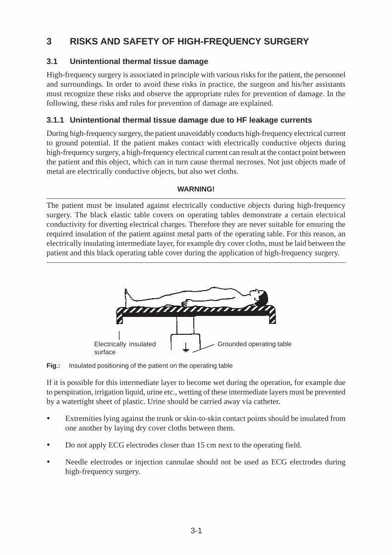
The patient must be insulated against electrically conductive objects during high-frequencysurgery. The black elastic table covers on operating tables demonstrate a certain electricalconductivity for diverting electrical charges. Therefore they are never suitable for ensuring therequired insulation of the patient against metal parts of the operating table. For this reason, anelectrically insulating intermediate layer, for example dry cover cloths, must be laid between thepatient and this black operating table cover during the application of high-frequency surgery.
Fig.: Insulated positioning of the patient on the operating table
If it is possible for this intermediate layer to become wet during the operation, for example dueto perspiration, irrigation liquid, urine etc., wetting of these intermediate layers must be preventedby a watertight sheet of plastic. Urine should be carried away via catheter.
� Extremities lying against the trunk or skin-to-skin contact points should be insulated fromone another by laying dry cover cloths between them.
� Do not apply ECG electrodes closer than 15 cm next to the operating field.
� Needle electrodes or injection cannulae should not be used as ECG electrodes duringhigh-frequency surgery.
Electrically insulatedsurface
Grounded operating table
3-2
3.1.2 Unintentional activation of an HF generator
Unintentional activation of an HF generator can lead to burns on the patient if the active electrodehereby touches the patient directly or indirectly through electrically conductive objects or wetcloths.
Unintentional activation of an HF generator can, for example, be caused by:
� Unintentionally pressing a footswitch pedal
� Unintentionally pressing a fingerswitch
� Defective fingerswitches, footswitches or cables
� Penetration of electrically conductive liquids (blood, amniotic fluid, urine, physiologicalsaline solution, irrigation fluids etc.) into fingerswitches or footswitches.
� Errors within the high-frequency surgical unit
WARNING !
To prevent burns on the patient due to unintentional activation of a high-frequency generator, thefollowing application rules should be heeded:
� Never lay active electrodes onto or beside a patient in such a way that they can touch thepatient directly or indirectly through electrically conductive objects or wet cloths.
� The lines to the active electrodes should be positioned in such a way that they touchneither the patient nor other lines.
� Always set the acoustic signal, which indicates the active status of the high-frequencygenerator, so that it can be easily heard.
� For operations in which the cutting or coagulation electrode unavoidably remains in contactwith the patient even in a nonactive condition, e.g. for endoscopic operations, particularcare is required. If such an electrode is unintentionally activated due to an error, this activatedelectrode should then not be removed from the body without special supervision. Whenremoving the activated electrode from the patient’s body, burns can result on all areaswithin the body which come into contact with the activated electrode. For this reason, incase such errors occur, the power switch for the high-frequency surgical unit should beswitched off immediately before an attempt is made to remove the activated electrodefrom the body.
3-3
3.1.3 Unintentional thermal tissue damage due to inappropriate application
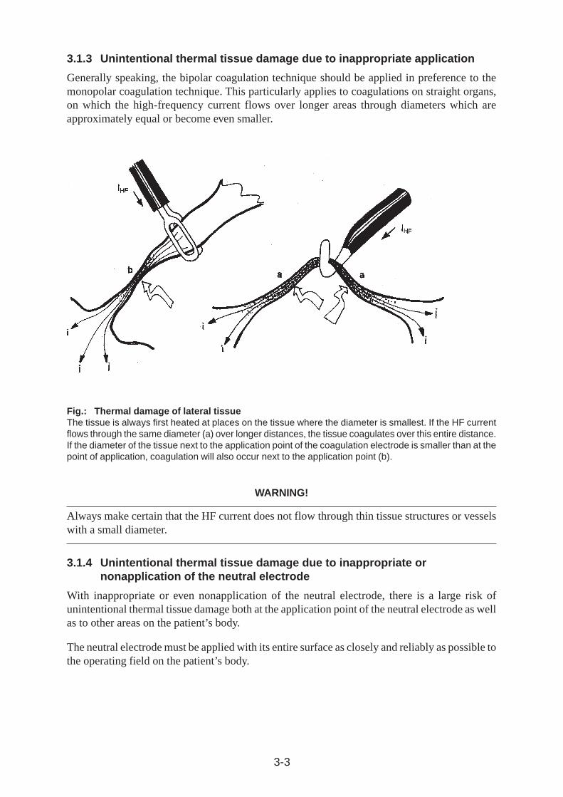
Generally speaking, the bipolar coagulation technique should be applied in preference to themonopolar coagulation technique. This particularly applies to coagulations on straight organs,on which the high-frequency current flows over longer areas through diameters which areapproximately equal or become even smaller.
Fig.: Thermal damage of lateral tissueThe tissue is always first heated at places on the tissue where the diameter is smallest. If the HF currentflows through the same diameter (a) over longer distances, the tissue coagulates over this entire distance.If the diameter of the tissue next to the application point of the coagulation electrode is smaller than at thepoint of application, coagulation will also occur next to the application point (b).
WARNING!
Always make certain that the HF current does not flow through thin tissue structures or vesselswith a small diameter.
3.1.4 Unintentional thermal tissue damage due to inappropriate ornonapplication of the neutral electrode
With inappropriate or even nonapplication of the neutral electrode, there is a large risk ofunintentional thermal tissue damage both at the application point of the neutral electrode as wellas to other areas on the patient’s body.
The neutral electrode must be applied with its entire surface as closely and reliably as possible tothe operating field on the patient’s body.
3-4
WARNING!
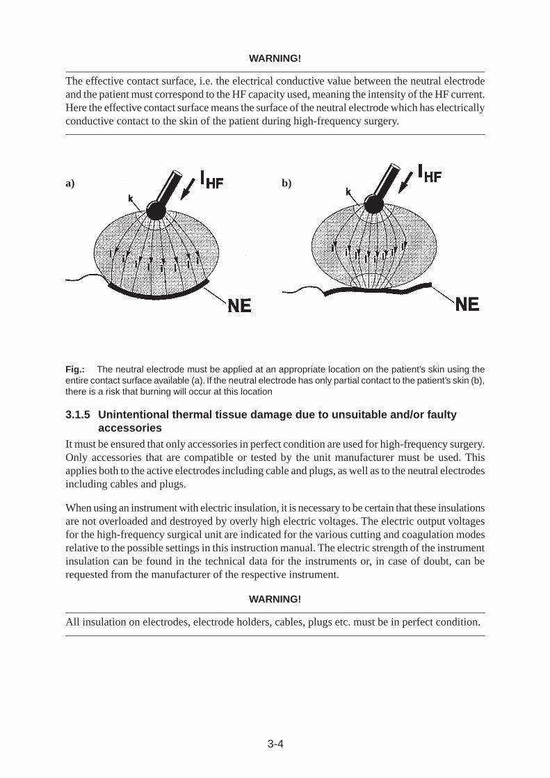
The effective contact surface, i.e. the electrical conductive value between the neutral electrodeand the patient must correspond to the HF capacity used, meaning the intensity of the HF current.Here the effective contact surface means the surface of the neutral electrode which has electricallyconductive contact to the skin of the patient during high-frequency surgery.
Fig.: The neutral electrode must be applied at an appropriate location on the patient’s skin using theentire contact surface available (a). If the neutral electrode has only partial contact to the patient’s skin (b),there is a risk that burning will occur at this location
3.1.5 Unintentional thermal tissue damage due to unsuitable and/or faultyaccessories
It must be ensured that only accessories in perfect condition are used for high-frequency surgery.Only accessories that are compatible or tested by the unit manufacturer must be used. Thisapplies both to the active electrodes including cable and plugs, as well as to the neutral electrodesincluding cables and plugs.
When using an instrument with electric insulation, it is necessary to be certain that these insulationsare not overloaded and destroyed by overly high electric voltages. The electric output voltagesfor the high-frequency surgical unit are indicated for the various cutting and coagulation modesrelative to the possible settings in this instruction manual. The electric strength of the instrumentinsulation can be found in the technical data for the instruments or, in case of doubt, can berequested from the manufacturer of the respective instrument.
WARNING!
All insulation on electrodes, electrode holders, cables, plugs etc. must be in perfect condition.
a) b)
3-5
3.1.6 Unintentional thermal tissue damage due to inattentivenessLike a scalpel, high-frequency surgery is always a potential source of danger if handled withoutcare.
WARNING!
The cutting or coagulation electrodes should always be handled with care and laid aside in theintervals between use so that neither the patient nor other persons can come in contact with theelectrodes.
Laying unused electrode handles or coagulation forceps on the patient, next to the patient orwithin folds on the cover cloths is dangerous. Cases of burns on patients are known which werecaused by laying the coagulation forceps within folds on the cover cloths which penetratedthrough the cloths into the patient’s skin and resulted in burns without being noticed.
3.1.7 Unintentional thermal tissue damage due to output error
The risk of unintentional thermal tissue damage is proportionate to the intensity and time limitset on the unit for cutting or coagulation.
WARNING!
The intensity for cutting or coagulation should only be set and only activated for as long asnecessary for the intended purpose.
An insufficient effect at a standard setting can, for example, be caused by poor attachment of theneutral electrode, poor contact in the connectors, defective cables or electrically insulating tissueremnants on the active electrode. This must be checked before setting at a higher power.
3.1.8 Unintentional thermal tissue damage due to the ignition of flammableliquids, gases and/or vapors
During high-frequency surgery, electric sparks or arcs that can ignite flammable liquids, gasesor vapors occur at the active electrode.
3-6
WARNING!
Make certain during high-frequency surgical operations that anesthetics, skin cleaning agentsand disinfectants are nonflammable. If their use is unavoidable, they must have completelyevaporated and the vapor must be removed from the area of spark formation before switching onthe high-frequency surgical unit.
Before application of high-frequency surgery in the gastro-intestinal tract, it must be ensuredthat no flammable (endogenous) gases are present here. There is danger of explosion if flammablegases are present. For this reason, these gases must be extracted and/or eliminated by flushingout the affected lumen with CO2before using high-frequency surgery.
During transurethral resection (TUR), H2O molecules may dissociate into H
2 and O
2 in the arc
between the resection loop and the irrigation liquid. These gases may collect on the roof of theurinary bladder as a highly explosive gas mixture. If resection is performed in this gas mixture,dangerous explosions may occur.
3.1.9 Unintentional burns due to hot electrodes
Cutting and/or coagulation electrodes become hot during cutting and/or coagulation proceduresindirectly through the heated tissue and through the electric arc.
WARNING!
Tissue can be unintentionally burnt immediately after cutting and/or coagulation procedures ifelectrodes that are still hot touch the tissue. Attention must be especially paid to this duringendoscopic operations, such as during pelviscopic fallopian tube coagulation or during endoscopicpolypectomy.
3.2 Electric shock
An electric shock may occur if the high-frequency surgical unit delivers a too heavy low-frequencycurrent or if a too heavy low-frequency current flows through the patient into the high-frequencysurgical unit from another voltage source.
3.3 Stimulation of nerves and muscles
A known risk of high-frequency surgery is the unintentional electric stimulation of the patient’snerves and muscles. This stimulation can result from low-frequency electrical currents that arecaused either by low-frequency current sources or due to electrical arcs between an active electrodeand the patient’s tissue.
Electric alternating current with a frequency above 300 kHz is unable to stimulate nerves andmuscles.
3-7
During cutting procedures, forced coagulation and spray coagulation, the unavoidable electricarcs between an active electrode and the tissue nevertheless have the effect that a portion of thehigh-frequency alternating current is rectified, from which more or less strongly modulated,low-frequency current components result which stimulate electrically stimulable structures suchas nerves and muscles.
This can result in more or less strong spasms or muscle contractions.
WARNING!
When using high-frequency surgery on electrically stimulable structures, contractions of theaffected muscles must be taken into account. This can occur, for example, during endoscopicoperations in the urinary bladder in the vicinity of the obturator nerve and during operations inthe area of the facial nerve.
3.4 Cardiac pacemaker
For patients with implanted cardiac pacemakers or pacemaker electrodes, irreparable damage tothe pacemaker and disturbance of the pacemaker function, which can lead to ventricular fibrilation,must be reckoned with.
3.5 Danger of explosion
High-frequency surgical units always generate sparks during operation on the active electrode.For this reason, it is necessary to make certain during interventions that anesthetics, degreasersand disinfectants are neither flammable nor explosive. They should at least have evaporatedcompletely before switching on the high-frequency surgical unit and be removed from the areaof spark formation.
3.6 Interference with other electronic equipment
High-frequency surgical units normally generate high-frequency electrical voltages and currentswhich can interfere with other electronic equipment.
When installing or arranging sensitive electronic equipment in the operating room, this problemshould be taken into consideration. In principle, sensitive electronic equipment should be set upas far as possible from the high-frequency surgical unit and particularly from the cables providingHF current. In addition, the cables providing HF current, which act like broadcast antennas,should not be unnecessarily long and should never be positioned parallel or too close to cablesfrom sensitive electronic equipment.
The unit has been fitted with a special generator in consideration of the disturbance of sensitiveelectronic equipment, which generates a relatively low interference level as compared toconventional high-frequency surgical units.
3.7 Portable and mobile communication equipment HF
ATTENTION: Portable and mobile communication equipment HF can influence the device.

3-8
International
Standard

4-1
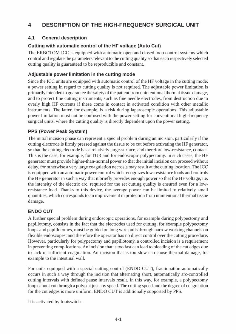
4 DESCRIPTION OF THE HIGH-FREQUENCY SURGICAL UNIT
4.1 General description
Cutting with automatic control of the HF voltage (Auto Cut)The ERBOTOM ICC is equipped with automatic open and closed loop control systems whichcontrol and regulate the parameters relevant to the cutting quality so that each respectively selectedcutting quality is guaranteed to be reproducible and constant.
Adjustable power limitation in the cutting modeSince the ICC units are equipped with automatic control of the HF voltage in the cutting mode,a power setting in regard to cutting quality is not required. The adjustable power limitation isprimarily intended to guarantee the safety of the patient from unintentional thermal tissue damage,and to protect fine cutting instruments, such as fine needle electrodes, from destruction due tooverly high HF currents if these come in contact in activated condition with other metallicinstruments. The latter, for example, is a risk during laparoscopic operations. This adjustablepower limitation must not be confused with the power setting for conventional high-frequencysurgical units, where the cutting quality is directly dependent upon the power setting.
PPS (Power Peak System)The initial incision phase can represent a special problem during an incision, particularly if thecutting electrode is firmly pressed against the tissue to be cut before activating the HF generator,so that the cutting electrode has a relatively large-surface, and therefore low-resistance, contact.This is the case, for example, for TUR and for endoscopic polypectomy. In such cases, the HFgenerator must provide higher-than-normal power so that the initial incision can proceed withoutdelay, for otherwise a very large coagulation necrosis may result at the cutting location. The ICCis equipped with an automatic power control which recognizes low-resistance loads and controlsthe HF generator in such a way that it briefly provides enough power so that the HF voltage, i.e.the intensity of the electric arc, required for the set cutting quality is ensured even for a low-resistance load. Thanks to this device, the average power can be limited to relatively smallquantities, which corresponds to an improvement in protection from unintentional thermal tissuedamage.
ENDO CUTA further special problem during endoscopic operations, for example during polypectomy andpapillotomy, consists in the fact that the electrodes used for cutting, for example polypectomyloops and papillotomes, must be guided on long wire pulls through narrow working channels onflexible endoscopes, and therefore the operator has no direct control over the cutting procedure.However, particularly for polypectomy and papillotomy, a controlled incision is a requirementin preventing complications. An incision that is too fast can lead to bleeding of the cut edges dueto lack of sufficient coagulation. An incision that is too slow can cause thermal damage, forexample to the intestinal wall.
For units equipped with a special cutting control (ENDO CUT), fractionation automaticallyoccurs in such a way through the incision that alternating short, automatically arc-controlledcutting intervals with defined pause intervals result. In this way, for example, a polypectomyloop cannot cut through a polyp at just any speed. The cutting speed and the degree of coagulationfor the cut edges is more uniform. ENDO CUT is additionally supported by PPS.
It is activated by footswitch.
4-2
Soft coagulationSoft coagulation can be activated by key or pedal.
Forced coagulationForced coagulation is advantageous if an efficient hemostasis is to be achieved with relativelysmall-surface electrodes, such as TUR resection loops.
Adjustable power limitation in the various coagulation modesFor the ERBOTOM ICC units, the surgically relevant coagulation qualities, i.e. the coagulationeffects Soft Coag., Forced Coag. and Bipolar Coag., are delimited by definition from one anotherand selectable by the press of a key. Nevertheless, the intensity of the different effects can bevaried by power limitation.
Operating mode for Argon Gas CoagulationFor units equipped with the Argon Coag operating mode, the ERBOTOM ICC 200 supplies apulsating HF voltage with peak values up to 4,000 V
P for Argon Gas Coagulation.
Bipolar coagulationIn this coagulation mode, the HF voltage is, similar to Soft coagulation, automatically andconstantly controlled, and its peak value always remains lower than 200 Vp, so that the currentdensity and thus the coagulation effect is, for the most part, independent of the effective contactsurface between the coagulation electrode and the tissue, provided the effective contact surfaceis not too large relative to the currently set power limitation.
The adjustable power limitation serves the purpose of protecting fine bipolar coagulationinstruments, such as pointed bipolar coagulation forceps, from being thermally destroyed incase of a short between the two forcep tips.
The footswitch or Auto Start is used for activation.
In the Auto Start mode, the HF generator is automatically activated if both poles of the bipolarcoagulation instruments used contact electrically conductive tissue simultaneously. Auto Startcan occur either immediately at the moment of contact with the tissue or more or less temporallydelayed. With immediate activation, it is possible to work very quickly, especially if severalcoagulations must be performed one after another. Delayed activation offers the operator theadvantage that he/she can prepare and securely grasp the tissue to be coagulated with the bipolarcoagulation forceps before the HF generator is automatically activated. Automatic activation ofthe HF generator only occurs if both poles of the bipolar coagulation instruments contact thetissue uninterruptedly for at least as long as the respectively selected delay lasts. If the contact isinterrupted before the respectively selected period of delay is over, the respective period of delayrestarts as of the next contact.
4-3
4.2 Description of the controls
This symbol, in accordance with EN 60 601-1, is intended to indicate to the userthat this unit must only be used on the patient if the user is acquainted with theoperation and features of this unit.
The figures set in cursive relate to the ICC illustration for this chapter, or to the functionfields in the text.
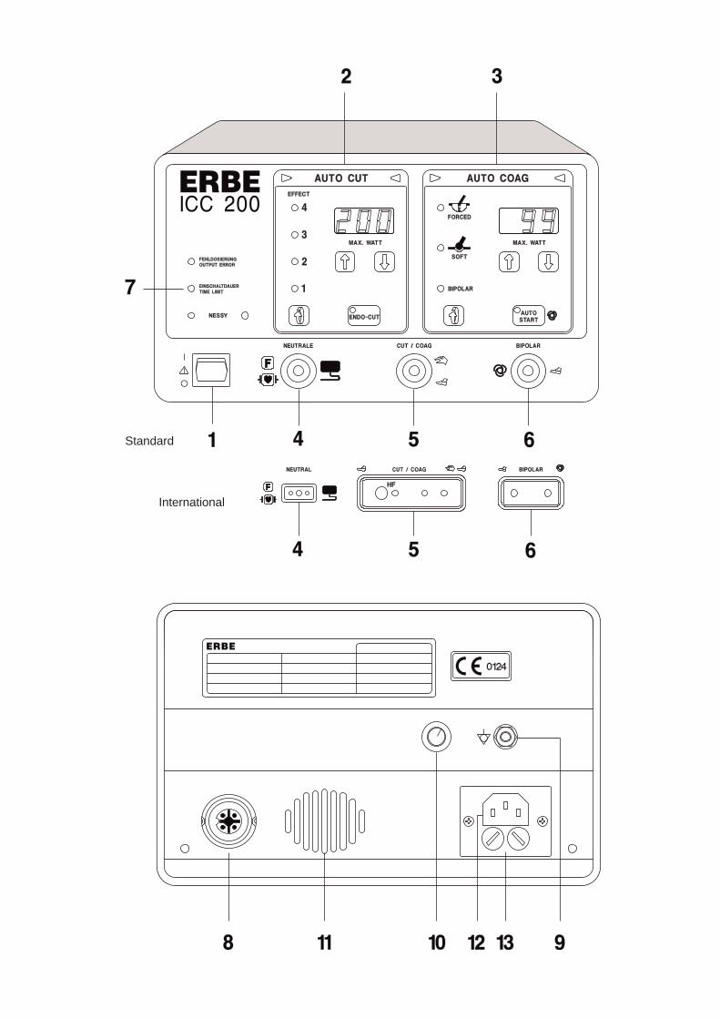
1 Power switchUsing this power switch, the unit is switched on and off.
Each time after being switched on, the unit automatically proceeds with various performancechecks. If an error in the unit or in the accessories is recognized here, a warning signalsounds and the determined error is indicated by a corresponding error number. (See Chapter8.1, Automatic performance checks after switching on the unit). If no error is determined,the unit is ready to operate.
If the unit was switched off for less than approx. 15 seconds, all settings for the programused before switching off appear after the automatic performance check on the front panel,and the unit can be immediately reactivated. This is advantageous if, for example, thepower supply briefly fails.
If the unit was switched off for longer than approx. 15 seconds, the basic setting of theprogram used before switching off appears after the automatic performance check on thefront panel, whereby all relevant visual displays continue to blink and the unit cannot beactivated until any key on the front panel is briefly pressed as confirmation that this programshould be used. Then the relevant displays are continously illuminated and the unit can beactivated using the available settings. These settings can be changed or adapted to thecurrent requirements at any time. However, other programs can be selected as well.
2 - 3 Function fieldsThe AUTO CUT and AUTO COAG function fields can be adjusted separately from oneanother, although not activated simultaneously for reasons of safety.
WARNING!
Function fields that are not used may be switched off completely to prevent unintentionalactivation. To do this, the power limitation must be set down so far in the corresponding functionfield until a beep is heard and “ —“ appears on the digital display. The corresponding functionfield cannot be activated in this condition.
4-4
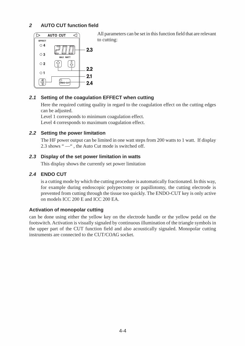
2 AUTO CUT function field
All parameters can be set in this function field that are relevantto cutting:
2.1 Setting of the coagulation EFFECT when cuttingHere the required cutting quality in regard to the coagulation effect on the cutting edgescan be adjusted.Level 1 corresponds to minimum coagulation effect.Level 4 corresponds to maximum coagulation effect.
2.2 Setting the power limitationThe HF power output can be limited in one watt steps from 200 watts to 1 watt. If display2.3 shows “ —“ , the Auto Cut mode is switched off.
2.3 Display of the set power limitation in wattsThis display shows the currently set power limitation
2.4 ENDO CUTis a cutting mode by which the cutting procedure is automatically fractionated. In this way,for example during endoscopic polypectomy or papillotomy, the cutting electrode isprevented from cutting through the tissue too quickly. The ENDO-CUT key is only activeon models ICC 200 E and ICC 200 EA.
Activation of monopolar cuttingcan be done using either the yellow key on the electrode handle or the yellow pedal on thefootswitch. Activation is visually signaled by continuous illumination of the triangle symbols inthe upper part of the CUT function field and also acoustically signaled. Monopolar cuttinginstruments are connected to the CUT/COAG socket.
4-5
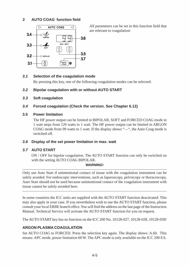
3 AUTO COAG function field
All parameters can be set in this function field thatare relevant to coagulation:
3.1 Selection of the coagulation modeBy pressing this key, one of the following coagulation modes can be selected:
3.2 Bipolar coagulation with or without AUTO START
3.3 Soft coagulation
3.4 Forced coagulation (Check the version. See Chapter 6.12)
3.5 Power limitationThe HF power output can be limited in BIPOLAR, SOFT and FORCED COAG mode in1 watt steps from 120 watts to 1 watt. The HF power output can be limited in ARGONCOAG mode from 99 watts to 1 watt. If the display shows “—“, the Auto Coag mode isswitched off.
3.6 Display of the set power limitation in max. watt
3.7 AUTO STARTON / OFF for bipolar coagulation. The AUTO START function can only be switched onwith the setting AUTO COAG BIPOLAR.
WARNING!
Only use Auto Start if unintentional contact of tissue with the coagulation instrument can besafely avoided. For endoscopic interventions, such as laparoscopy, pelviscopy or thoracoscopy,Auto Start should not be used because unintentional contact of the coagulation instrument withtissue cannot be safely avoided here.
In some countries the ICC units are supplied with the AUTO START function deactivated. Thismay also apply in your case. If you nevertheless wish to use the AUTO START function, pleaseconsult your local ERBE branch office. You will find the address on the last page of the InstructionManual. Technical Service will activate the AUTO START function for you on request.
The AUTO START key has no function on the ICC 200 No. 10128-027, 10128-028, 10128-058!
ARGON PLASMA COAGULATIONSet AUTO COAG to FORCED. Press the selection key again. The display shows: A.60. Thismeans: APC mode, power limitation 60 W. The APC mode is only available on the ICC 200 EA.
4-6
4 Connecting socket for neutral electrodesFor monopolar cutting and/or coagulation, a suitable neutral electrode must be used that mustboth be connected to the unit as well as carefully applied to the patient.
The ICC is equipped with a Neutral Electrode Monitoring System (NESSY) which automaticallymonitors the electrical connection between the neutral electrode and the unit as well as applicationof the neutral electrode on the patient. The latter only then however if neutral electrodes withtwo contact surfaces are used.
WARNING!
If single-surface neutral electrodes are used, NESSY only monitors the electrical connectionbetween the neutral electrode and the unit, but not the application of the neutral electrode on thepatient.
The pictograms beside the connecting socket for neutral electrodes have the following explanation:
Neutral electrode in general
The unit conforms to the requirements in EN 60 601-2-2, Sec. 19.101b, accordingto which the applied part of the unit is insulated to ground potential compatible toHF technology.
The ICC conforms to the requirements of Type CF in accordance with EN 60601-1. In addition, this pictogram indicates, in accordance with EN 60 601-2-2,that the neutral electrode can remain applied to the patient during defibrillation.
5 Connecting socket for monopolar cutting or coagulation instrumentsElectrode handles with or without fingerswitches can be operated at this connecting socket.Other instruments, such as electrodes for rigid or flexible endoscopes for endoscopic operations,can be connected to this connecting socket. Attention must be paid here to the correct plug type.This connecting socket can be activated via fingerswitch or the pedals of a footswitch.
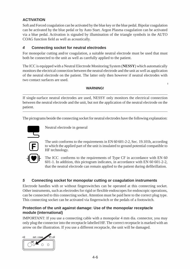
Protection of the unit against damage: Use of the monopolar receptaclemodule (international)IMPORTANT: If you use a connecting cable with a monopolar 4 mm dia. connector, you mayonly plug the connector into the receptacle labelled HF. The correct receptacle is marked with anarrow on the illustration. If you use a different receptacle, the unit will be damaged.
ACTIVATIONSoft and Forced coagulation can be activated by the blue key or the blue pedal. Bipolar coagulationcan be activated by the blue pedal or by Auto Start. Argon Plasma coagulation can be activatedvia a blue pedal. Activation is signaled by illumination of the triangle symbols in the AUTOCOAG function field as well as acoustically.
HF
4-7
6 Connecting socket for bipolar coagulation instrumentsBipolar instruments can be connected to this connecting socket. The bipolar coagulation modeis activated via pedal or Auto Start.
CAUTION!
When using pointed bipolar coagulation forceps, the tips can be thermally damaged due to electriccurrents that are too high. To prevent this, it is recommended that the power limitation be set aslow as possible and/or make certain that the tips of the bipolar coagulation forceps do not touchone another.
7 Safety fieldHigh-frequency surgical units of the ERBOTOM ICC series are equipped with various safetydevices to protect the patients and users.
8 Connecting socket for a dual-pedal footswitchA dual-pedal footswitch can be connected to this connecting socket. When using a dual-pedalfootswitch, the AUTO CUT function field can be activated with the yellow pedal and the AUTOCOAG function field can be activated with the blue pedal.
9 Terminal for potential equalizationFor this, see Chapter 6.4 “INSTALLATION“.
10 Volume of the acoustic signalThe volume of the acoustic signals can be set using this knob.This does not apply to warning signals, which must always be sufficiently loud.
WARNING!
An important purpose of this acoustic signal is to protect the patients and personnel from burnsdue to unintentional activation of the high-frequency generator (for more information, see Chapter3.1.2, Unintentional activation of a high-frequency generator).
11 Loudspeaker for acoustic signalsAlways set up the instrument in such a way that acoustic signals are easily heard from thisspeaker.
12 Power connectionThis high-frequency surgical unit must only be connected via the power cord supplied by theunit manufacturer or one of these of equal quality, which bears the national test symbol, tocorrectly installed hospital grade power sockets. Here, for reasons of safety, no multiple socketsor extension cords must be used if possible. If their use is unavoidable, they must be equippedwith a correctly functioning grounded connector.
13 Power fusesThe unit is secured with two fuses. If these fuses fail, an authorized technician should inspect theunit for possible errors before putting back into operation.
4-8
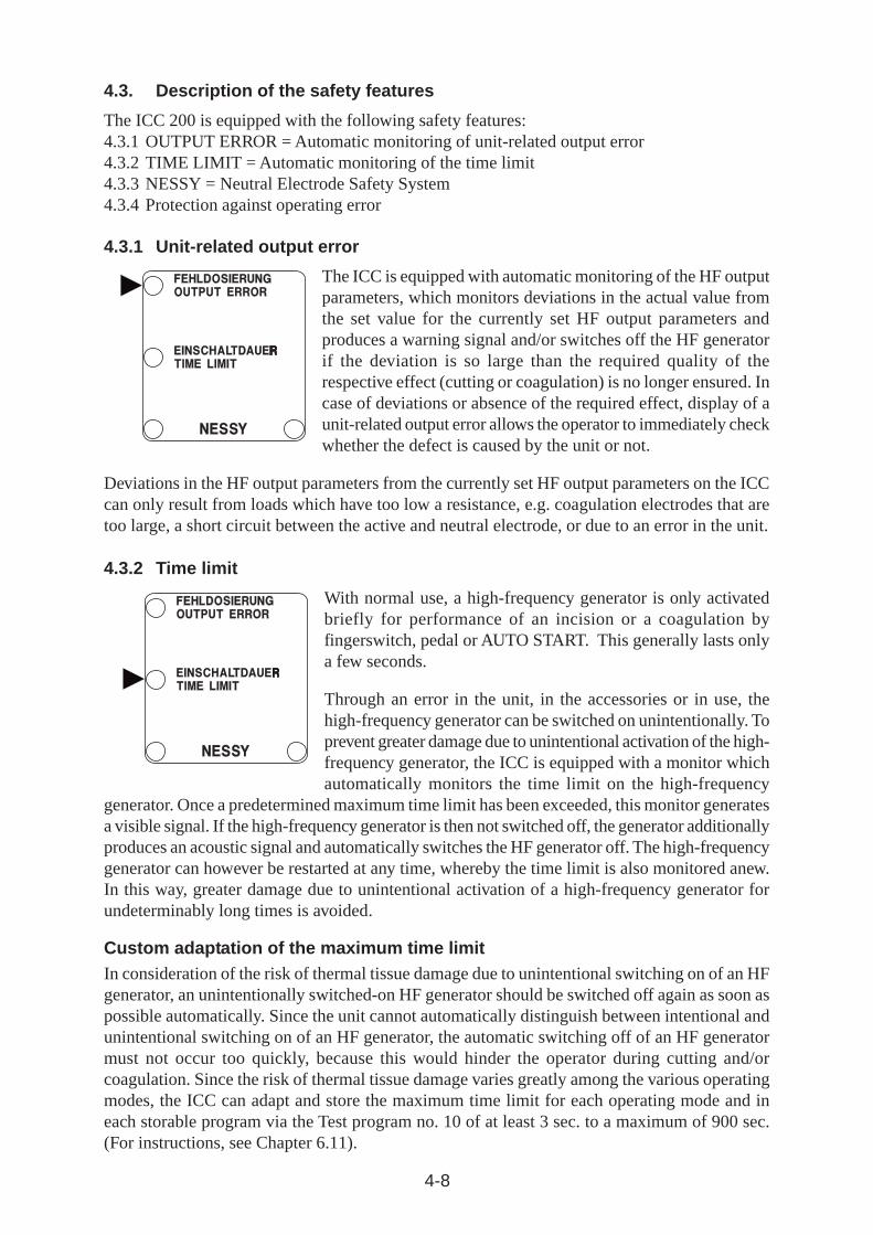
4.3.2 Time limit
With normal use, a high-frequency generator is only activatedbriefly for performance of an incision or a coagulation byfingerswitch, pedal or AUTO START. This generally lasts onlya few seconds.
Through an error in the unit, in the accessories or in use, thehigh-frequency generator can be switched on unintentionally. Toprevent greater damage due to unintentional activation of the high-frequency generator, the ICC is equipped with a monitor whichautomatically monitors the time limit on the high-frequency
generator. Once a predetermined maximum time limit has been exceeded, this monitor generatesa visible signal. If the high-frequency generator is then not switched off, the generator additionallyproduces an acoustic signal and automatically switches the HF generator off. The high-frequencygenerator can however be restarted at any time, whereby the time limit is also monitored anew.In this way, greater damage due to unintentional activation of a high-frequency generator forundeterminably long times is avoided.
Custom adaptation of the maximum time limitIn consideration of the risk of thermal tissue damage due to unintentional switching on of an HFgenerator, an unintentionally switched-on HF generator should be switched off again as soon aspossible automatically. Since the unit cannot automatically distinguish between intentional andunintentional switching on of an HF generator, the automatic switching off of an HF generatormust not occur too quickly, because this would hinder the operator during cutting and/orcoagulation. Since the risk of thermal tissue damage varies greatly among the various operatingmodes, the ICC can adapt and store the maximum time limit for each operating mode and ineach storable program via the Test program no. 10 of at least 3 sec. to a maximum of 900 sec.(For instructions, see Chapter 6.11).
4.3.1 Unit-related output error
The ICC is equipped with automatic monitoring of the HF outputparameters, which monitors deviations in the actual value fromthe set value for the currently set HF output parameters andproduces a warning signal and/or switches off the HF generatorif the deviation is so large than the required quality of therespective effect (cutting or coagulation) is no longer ensured. Incase of deviations or absence of the required effect, display of aunit-related output error allows the operator to immediately checkwhether the defect is caused by the unit or not.
Deviations in the HF output parameters from the currently set HF output parameters on the ICCcan only result from loads which have too low a resistance, e.g. coagulation electrodes that aretoo large, a short circuit between the active and neutral electrode, or due to an error in the unit.
4.3. Description of the safety features
The ICC 200 is equipped with the following safety features:4.3.1 OUTPUT ERROR = Automatic monitoring of unit-related output error4.3.2 TIME LIMIT = Automatic monitoring of the time limit4.3.3 NESSY = Neutral Electrode Safety System4.3.4 Protection against operating error
4-9
WARNING!
For reasons of safety, a change in the automatic limitation of the maximum time limit must onlybe made if all users of this unit are informed properly and in good time about this change.
In addition, a change in the automatic limitation of the maximum time limit must be properlydocumented, for example in the medical product logbook of the respective unit.
4-10
4.3.3 NESSY
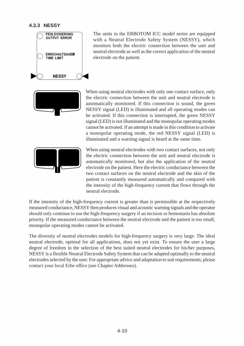
The units in the ERBOTOM ICC model series are equippedwith a Neutral Electrode Safety System (NESSY), whichmonitors both the electric connection between the unit andneutral electrode as well as the correct application of the neutralelectrode on the patient.
When using neutral electrodes with only one contact surface, onlythe electric connection between the unit and neutral electrode isautomatically monitored. If this connection is sound, the greenNESSY signal (LED) is illuminated and all operating modes canbe activated. If this connection is interrupted, the green NESSYsignal (LED) is not illuminated and the monopolar operating modescannot be activated. If an attempt is made in this condition to activatea monopolar operating mode, the red NESSY signal (LED) isilluminated and a warning signal is heard at the same time.
When using neutral electrodes with two contact surfaces, not onlythe electric connection between the unit and neutral electrode isautomatically monitored, but also the application of the neutralelectrode on the patient. Here the electric conductance between thetwo contact surfaces on the neutral electrode and the skin of thepatient is constantly measured automatically and compared withthe intensity of the high-frequency current that flows through theneutral electrode.
If the intensity of the high-frequency current is greater than is permissible at the respectivelymeasured conductance, NESSY then produces visual and acoustic warning signals and the operatorshould only continue to use the high-frequency surgery if an incision or hemostasis has absolutepriority. If the measured conductance between the neutral electrode and the patient is too small,monopolar operating modes cannot be activated.
The diversity of neutral electrodes models for high-frequency surgery is very large. The idealneutral electrode, optimal for all applications, does not yet exist. To ensure the user a largedegree of freedom in the selection of the best suited neutral electrodes for his/her purposes,NESSY is a flexible Neutral Electrode Safety System that can be adapted optimally to the neutralelectrodes selected by the user. For appropriate advice and adaptation to suit requirements, pleasecontact your local Erbe office (see Chapter Addresses).
4-11
WARNING!
For reasons of safety, a change to NESSY may only be made if it has been properly ensured thatall users of this unit are informed in good time about this change. In addition, a change toNESSY must be properly documented.
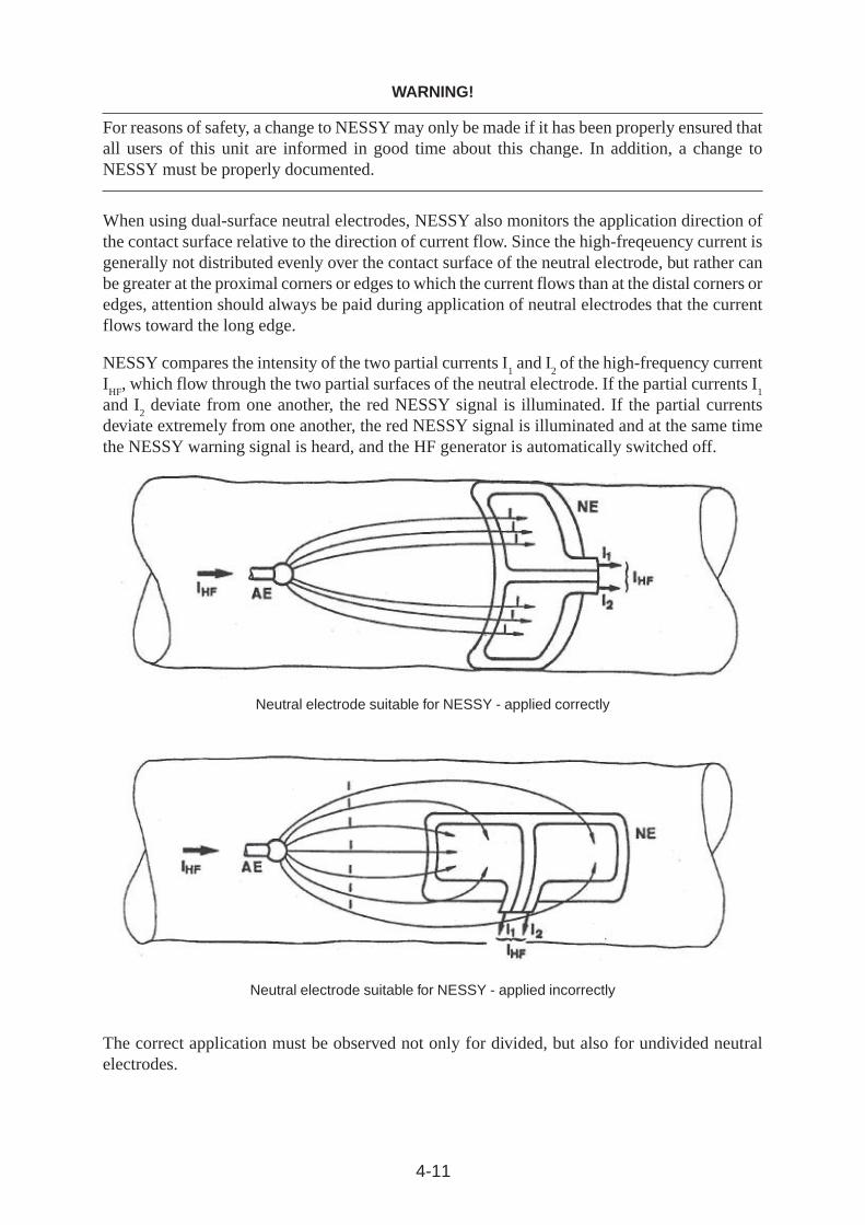
When using dual-surface neutral electrodes, NESSY also monitors the application direction ofthe contact surface relative to the direction of current flow. Since the high-freqeuency current isgenerally not distributed evenly over the contact surface of the neutral electrode, but rather canbe greater at the proximal corners or edges to which the current flows than at the distal corners oredges, attention should always be paid during application of neutral electrodes that the currentflows toward the long edge.
NESSY compares the intensity of the two partial currents I1 and I
2 of the high-frequency current
IHF
, which flow through the two partial surfaces of the neutral electrode. If the partial currents I1
and I2 deviate from one another, the red NESSY signal is illuminated. If the partial currents
deviate extremely from one another, the red NESSY signal is illuminated and at the same timethe NESSY warning signal is heard, and the HF generator is automatically switched off.
Neutral electrode suitable for NESSY - applied correctly
Neutral electrode suitable for NESSY - applied incorrectly
The correct application must be observed not only for divided, but also for undivided neutralelectrodes.
4-12
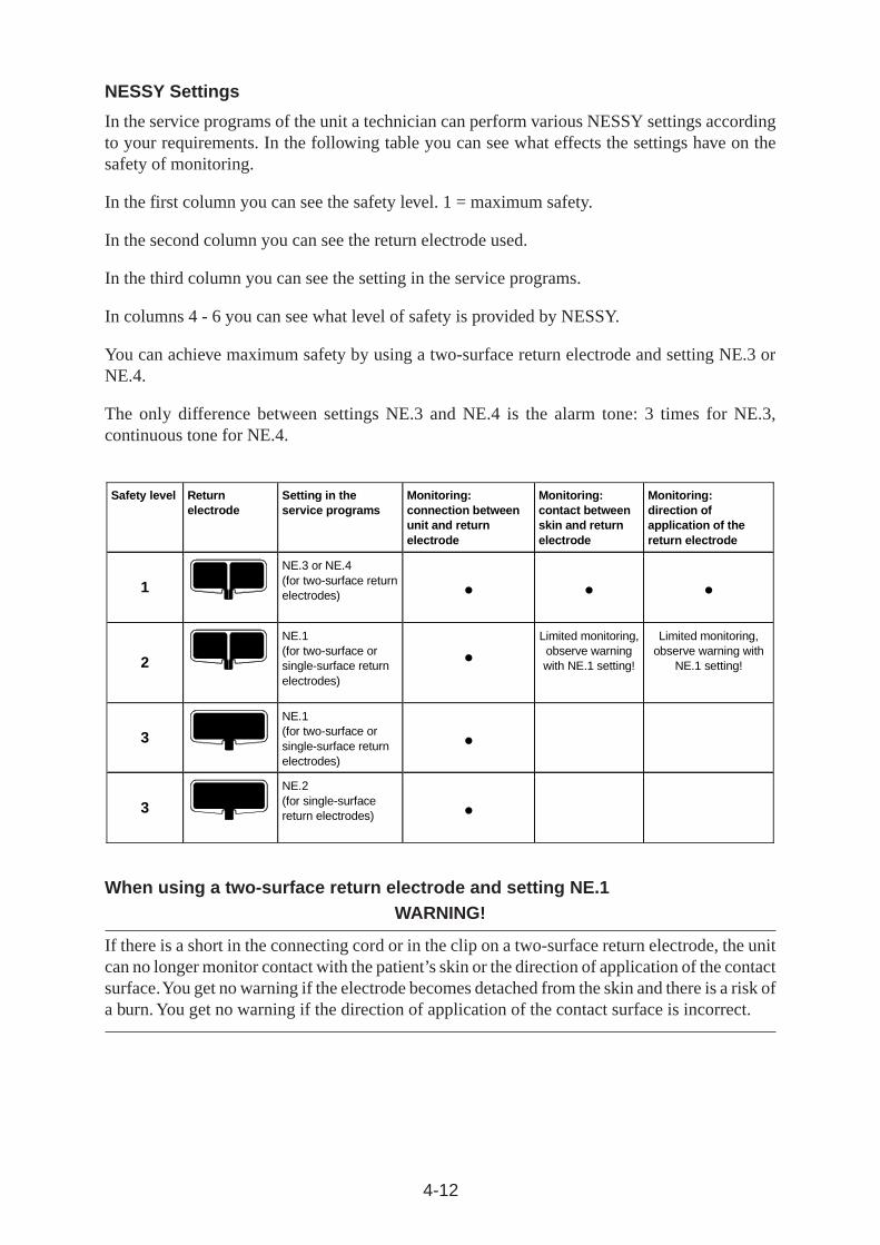
NESSY Settings
In the service programs of the unit a technician can perform various NESSY settings accordingto your requirements. In the following table you can see what effects the settings have on thesafety of monitoring.
In the first column you can see the safety level. 1 = maximum safety.
In the second column you can see the return electrode used.
In the third column you can see the setting in the service programs.
In columns 4 - 6 you can see what level of safety is provided by NESSY.
You can achieve maximum safety by using a two-surface return electrode and setting NE.3 orNE.4.
The only difference between settings NE.3 and NE.4 is the alarm tone: 3 times for NE.3,continuous tone for NE.4.
Safety level Return
electrode Setting in the service programs
Monitoring: connection between unit and return electrode
Monitoring: contact between skin and return electrode
Monitoring: direction of application of the return electrode
1
NE.3 or NE.4 (for two-surface return electrodes)
2
NE.1 (for two-surface or single-surface return electrodes)
Limited monitoring, observe warning with NE.1 setting!
Limited monitoring, observe warning with
NE.1 setting!
3
NE.1 (for two-surface or single-surface return electrodes)
3
NE.2 (for single-surface return electrodes)
When using a two-surface return electrode and setting NE.1WARNING!
If there is a short in the connecting cord or in the clip on a two-surface return electrode, the unitcan no longer monitor contact with the patient’s skin or the direction of application of the contactsurface. You get no warning if the electrode becomes detached from the skin and there is a risk ofa burn. You get no warning if the direction of application of the contact surface is incorrect.
4-13
Checking for a short in the connecting cord
In order to be sure there is no short in the connecting cord proceed as follows:
a) In the case of return electrodes without a permanently connected cordSwitch on the unit. Plug the connecting cord into the socket for the return electrode. The greenNESSY signal (LED) must NOT be lit. Only connect the cord to the return electrode when thishas been checked.
b) In the case of return electrodes with a permanently connected cordSwitch on the unit. Plug the connecting cord into the socket for the return electrode. The greenNESSY signal (LED) must NOT be lit. Only apply the return electrode when this has beenchecked on the patient.
4.3.4 Protection against operating error
To prevent operating errors, the front panel is designed in such a way that illogical and/orincomplete settings are automatically monitored and signaled.
The female connector beneath the front panel contains all the connecting sockets for the appliedpart.
These connecting sockets are designed in such a way that only plugs from intended accessoriescan be inserted (provided that only accessories recommended or supplied by the manufacturer ofthe unit are used).
Each time after switching on the power switch, an automatic test program is started within theunit which recognizes and signals the following errors in the operating controls for the unit andfor accessories connected to the unit:
1. If a key on the front panel is shorted or pressed due to an error when the power switch isswitched on, this error is indicated acoustically and by an Error Number after the powerswitch has been switched on.
2. If a key on the electrode handle is shorted or bypassed at low resistance due to an error(e.g. by moisture in the electrode handle) or pressed while the power switch is switchedon, this error is signaled acoustically and indicated by an Error Number after switching onthe power switch.
3. If a footswitch contact is shorted due to an error, a pedal sticks or a pedal is pressed whilethe power switch is switched on, this error is indicated acoustically and by an Error Number.
CAUTION!
Every function field can only then be activated if it has been completely set. If an attempt ismade to activate a function field which has not or not completely been set, the unit produces anintermittent acoustic warning signal and indicates this operating error by illumination of thetriangle symbols on the corresponding function field.

4-14
5-1
5 TECHNICAL DATA, SIGNALS, DIAGRAMS
5.1 Technical data
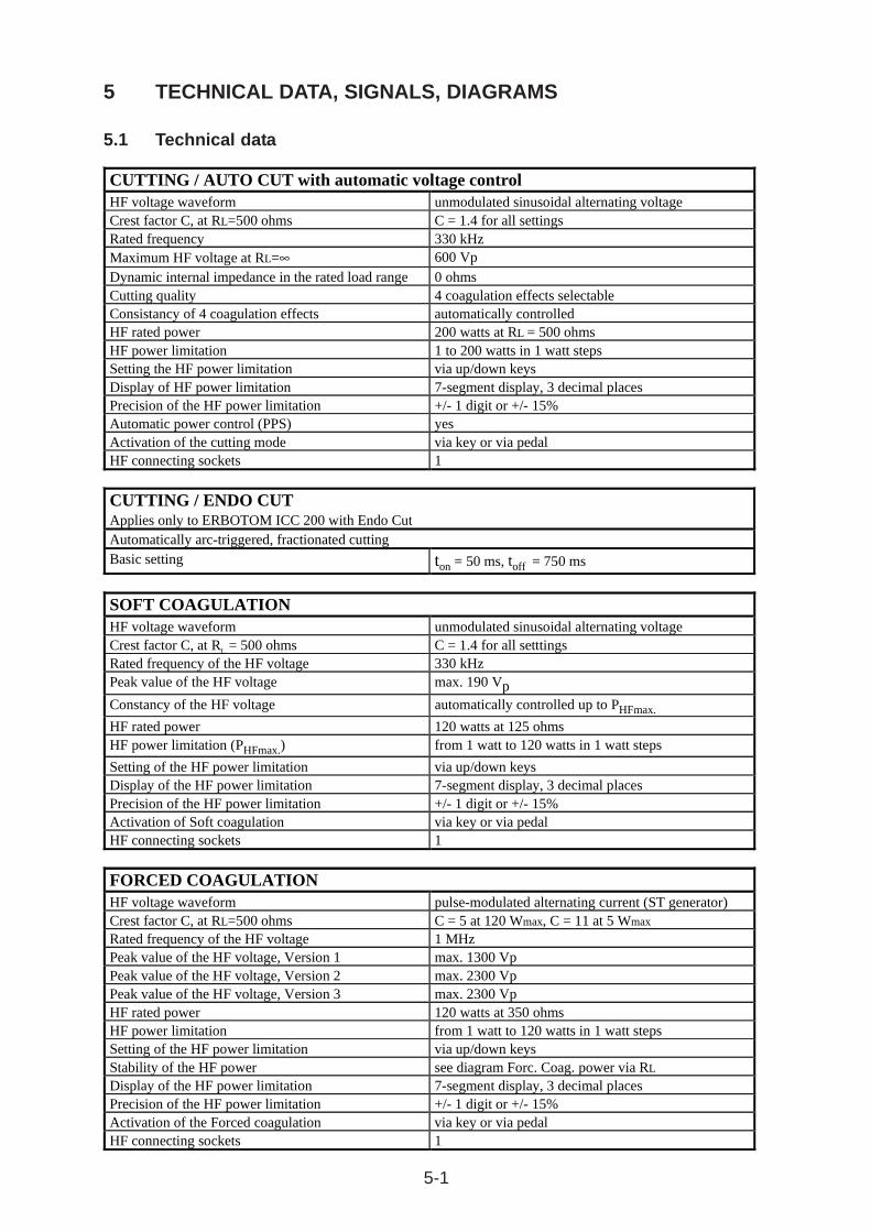
CUTTING / AUTO CUT with automatic voltage control HF voltage waveform unmodulated sinusoidal alternating voltage Crest factor C, at RL=500 ohms C = 1.4 for all settings Rated frequency 330 kHz Maximum HF voltage at RL=∞ 600 Vp Dynamic internal impedance in the rated load range 0 ohms Cutting quality 4 coagulation effects selectable Consistancy of 4 coagulation effects automatically controlled HF rated power 200 watts at RL = 500 ohms HF power limitation 1 to 200 watts in 1 watt steps Setting the HF power limitation via up/down keys Display of HF power limitation 7-segment display, 3 decimal places Precision of the HF power limitation +/- 1 digit or +/- 15% Automatic power control (PPS) yes Activation of the cutting mode via key or via pedal HF connecting sockets 1
CUTTING / ENDO CUT Applies only to ERBOTOM ICC 200 with Endo Cut Automatically arc-triggered, fractionated cutting Basic setting ton = 50 ms, toff = 750 ms
SOFT COAGULATION HF voltage waveform unmodulated sinusoidal alternating voltage Crest factor C, at RL = 500 ohms C = 1.4 for all setttings Rated frequency of the HF voltage 330 kHz Peak value of the HF voltage max. 190 Vp
Constancy of the HF voltage automatically controlled up to PHFmax.
HF rated power 120 watts at 125 ohms HF power limitation (PHFmax.) from 1 watt to 120 watts in 1 watt steps
Setting of the HF power limitation via up/down keys Display of the HF power limitation 7-segment display, 3 decimal places Precision of the HF power limitation +/- 1 digit or +/- 15% Activation of Soft coagulation via key or via pedal HF connecting sockets 1
FORCED COAGULATION HF voltage waveform pulse-modulated alternating current (ST generator) Crest factor C, at RL=500 ohms C = 5 at 120 Wmax, C = 11 at 5 Wmax Rated frequency of the HF voltage 1 MHz Peak value of the HF voltage, Version 1 max. 1300 Vp Peak value of the HF voltage, Version 2 max. 2300 Vp Peak value of the HF voltage, Version 3 max. 2300 Vp HF rated power 120 watts at 350 ohms HF power limitation from 1 watt to 120 watts in 1 watt steps Setting of the HF power limitation via up/down keys Stability of the HF power see diagram Forc. Coag. power via RL Display of the HF power limitation 7-segment display, 3 decimal places Precision of the HF power limitation +/- 1 digit or +/- 15% Activation of the Forced coagulation via key or via pedal HF connecting sockets 1
5-2
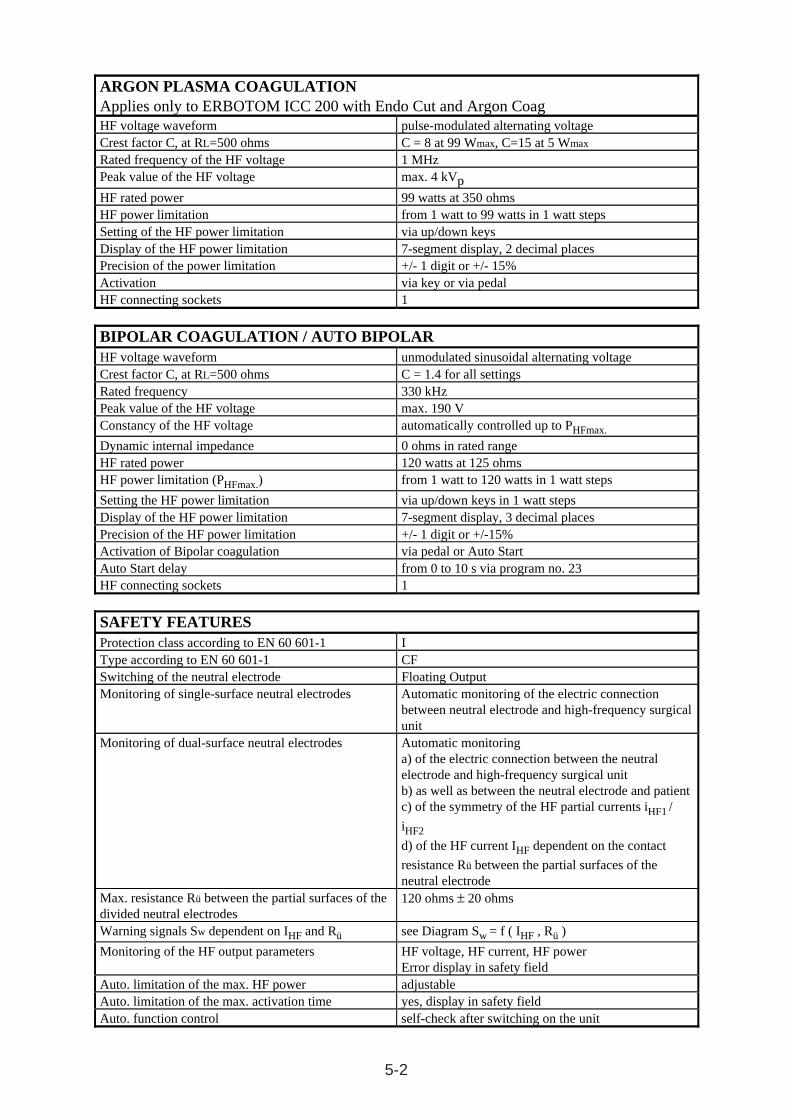
ARGON PLASMA COAGULATIONApplies only to ERBOTOM ICC 200 with Endo Cut and Argon CoagHF voltage waveform pulse-modulated alternating voltageCrest factor C, at RL=500 ohms C = 8 at 99 Wmax, C=15 at 5 Wmax
Rated frequency of the HF voltage 1 MHzPeak value of the HF voltage max. 4 kVpHF rated power 99 watts at 350 ohmsHF power limitation from 1 watt to 99 watts in 1 watt stepsSetting of the HF power limitation via up/down keysDisplay of the HF power limitation 7-segment display, 2 decimal placesPrecision of the power limitation +/- 1 digit or +/- 15%Activation via key or via pedalHF connecting sockets 1
BIPOLAR COAGULATION / AUTO BIPOLARHF voltage waveform unmodulated sinusoidal alternating voltageCrest factor C, at RL=500 ohms C = 1.4 for all settingsRated frequency 330 kHzPeak value of the HF voltage max. 190 VConstancy of the HF voltage automatically controlled up to PHFmax.
Dynamic internal impedance 0 ohms in rated rangeHF rated power 120 watts at 125 ohmsHF power limitation (PHFmax.) from 1 watt to 120 watts in 1 watt steps
Setting the HF power limitation via up/down keys in 1 watt stepsDisplay of the HF power limitation 7-segment display, 3 decimal placesPrecision of the HF power limitation +/- 1 digit or +/-15%Activation of Bipolar coagulation via pedal or Auto StartAuto Start delay from 0 to 10 s via program no. 23HF connecting sockets 1
SAFETY FEATURESProtection class according to EN 60 601-1 IType according to EN 60 601-1 CFSwitching of the neutral electrode Floating OutputMonitoring of single-surface neutral electrodes Automatic monitoring of the electric connection
between neutral electrode and high-frequency surgicalunit
Monitoring of dual-surface neutral electrodes Automatic monitoringa) of the electric connection between the neutralelectrode and high-frequency surgical unitb) as well as between the neutral electrode and patientc) of the symmetry of the HF partial currents iHF1 /
iHF2
d) of the HF current IHF dependent on the contact
resistance Rü between the partial surfaces of theneutral electrode
Max. resistance Rü between the partial surfaces of thedivided neutral electrodes
120 ohms ± 20 ohms
Warning signals Sw dependent on IHF and Rü see Diagram Sw = f ( IHF , Rü )
Monitoring of the HF output parameters HF voltage, HF current, HF powerError display in safety field
Auto. limitation of the max. HF power adjustableAuto. limitation of the max. activation time yes, display in safety fieldAuto. function control self-check after switching on the unit
5-3
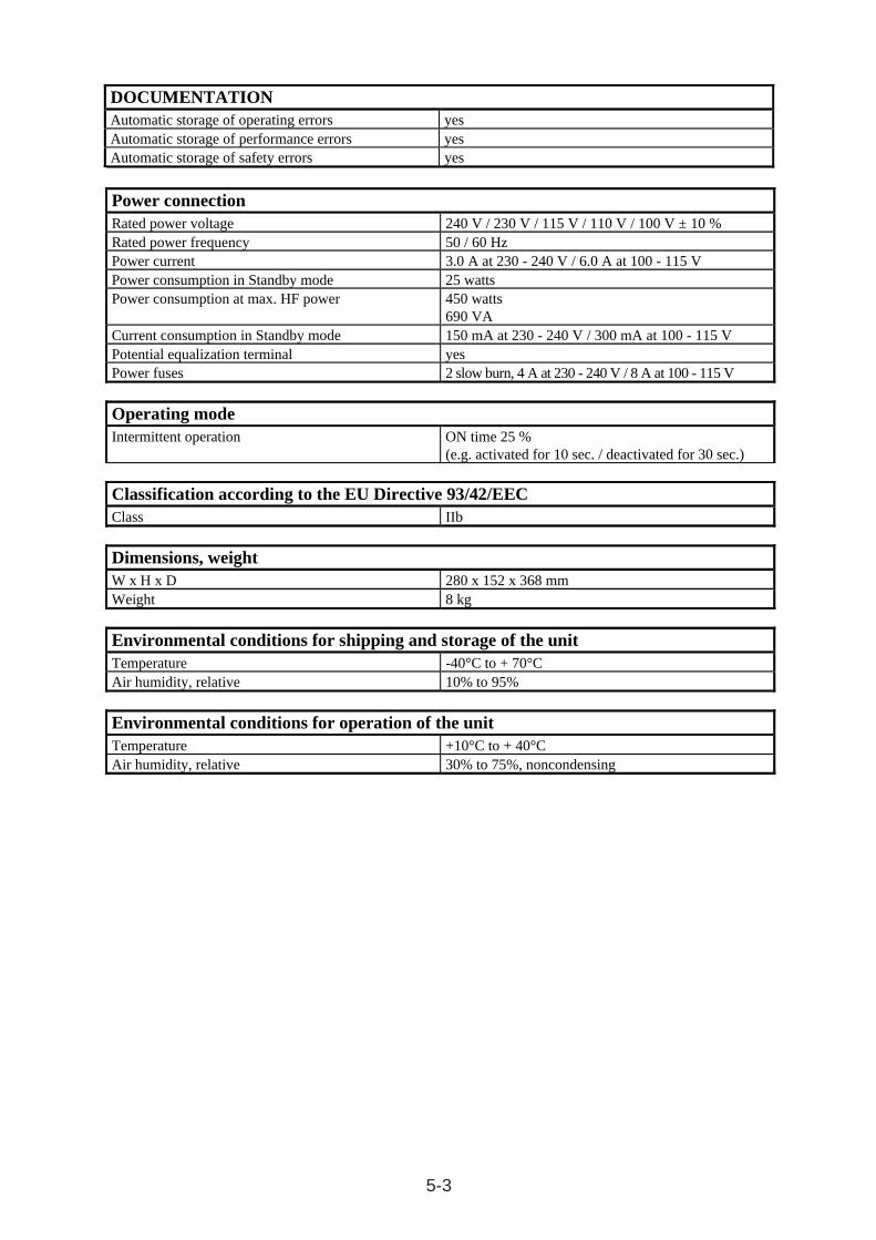
Power connection
Rated power voltage 240 V / 230 V / 115 V / 110 V / 100 V ± 10 % Rated power frequency 50 / 60 Hz Power current 3.0 A at 230 - 240 V / 6.0 A at 100 - 115 V Power consumption in Standby mode 25 watts Power consumption at max. HF power 450 watts
690 VA Current consumption in Standby mode 150 mA at 230 - 240 V / 300 mA at 100 - 115 V Potential equalization terminal yes Power fuses 2 slow burn, 4 A at 230 - 240 V / 8 A at 100 - 115 V
Operating mode
Intermittent operation ON time 25 % (e.g. activated for 10 sec. / deactivated for 30 sec.)
Classification according to the EU Directive 93/42/EEC
Class IIb
Dimensions, weight
W x H x D 280 x 152 x 368 mm Weight 8 kg
Environmental conditions for shipping and storage of the unit
Temperature -40°C to + 70°C Air humidity, relative 10% to 95%
Environmental conditions for operation of the unit
Temperature +10°C to + 40°C Air humidity, relative 30% to 75%, noncondensing
DOCUMENTATIONAutomatic storage of operating errors yesAutomatic storage of performance errors yesAutomatic storage of safety errors yes
5-4
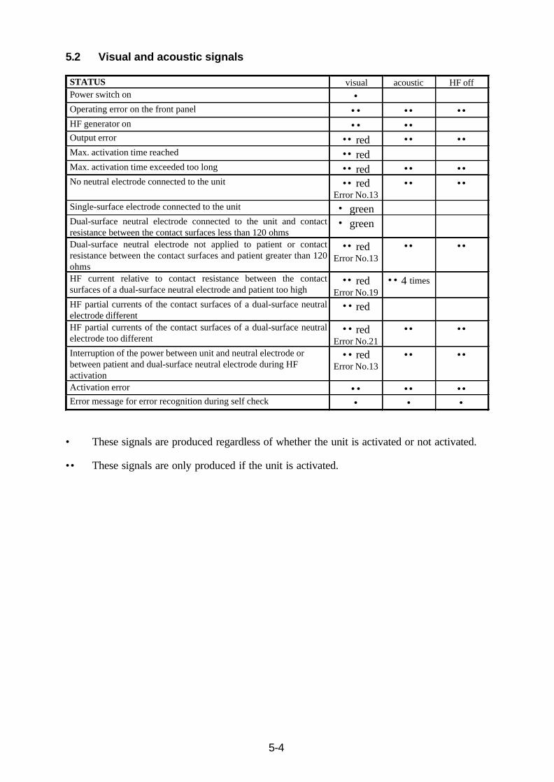
5.2 Visual and acoustic signals
• These signals are produced regardless of whether the unit is activated or not activated.
•• These signals are only produced if the unit is activated.
STATUS visual acoustic HF offPower switch on •Operating error on the front panel •• •• ••HF generator on •• ••Output error •• red •• ••Max. activation time reached •• redMax. activation time exceeded too long •• red •• ••No neutral electrode connected to the unit •• red
Error No.13•• ••
Single-surface electrode connected to the unit • greenDual-surface neutral electrode connected to the unit and contactresistance between the contact surfaces less than 120 ohms
• green
Dual-surface neutral electrode not applied to patient or contactresistance between the contact surfaces and patient greater than 120ohms
•• redError No.13
•• ••
HF current relative to contact resistance between the contactsurfaces of a dual-surface neutral electrode and patient too high
•• redError No.19
•• 4 times
HF partial currents of the contact surfaces of a dual-surface neutralelectrode different
•• red
HF partial currents of the contact surfaces of a dual-surface neutralelectrode too different
•• redError No.21
•• ••
Interruption of the power between unit and neutral electrode orbetween patient and dual-surface neutral electrode during HFactivation
•• redError No.13
•• ••
Activation error •• •• ••Error message for error recognition during self check • • •
5-5
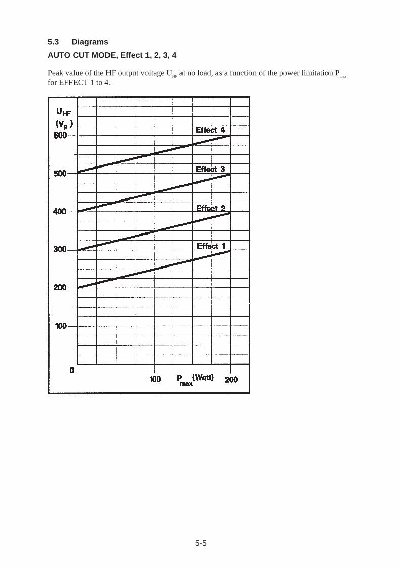
5.3 Diagrams
AUTO CUT MODE, Effect 1, 2, 3, 4
Peak value of the HF output voltage UHF
at no load, as a function of the power limitation Pmax
for EFFECT 1 to 4.
5-6
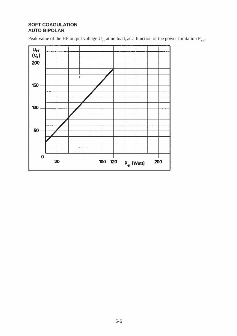
SOFT COAGULATIONAUTO BIPOLAR
Peak value of the HF output voltage UHF
at no load, as a function of the power limitation Pmax
.
5-7
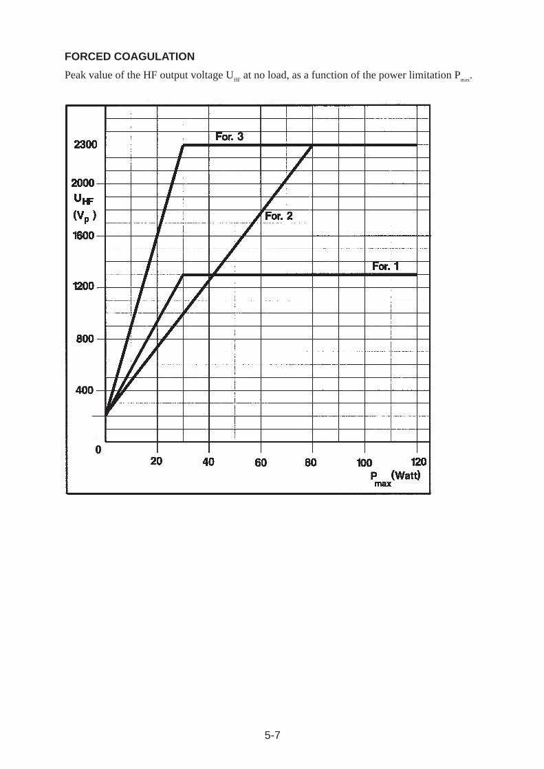
FORCED COAGULATION
Peak value of the HF output voltage UHF
at no load, as a function of the power limitation Pmax
.
5-8
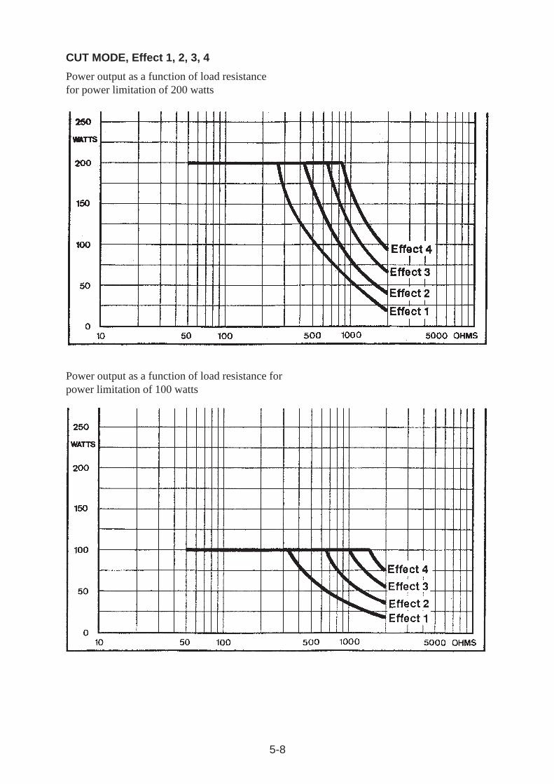
Power output as a function of load resistance forpower limitation of 100 watts
CUT MODE, Effect 1, 2, 3, 4
Power output as a function of load resistancefor power limitation of 200 watts
5-9
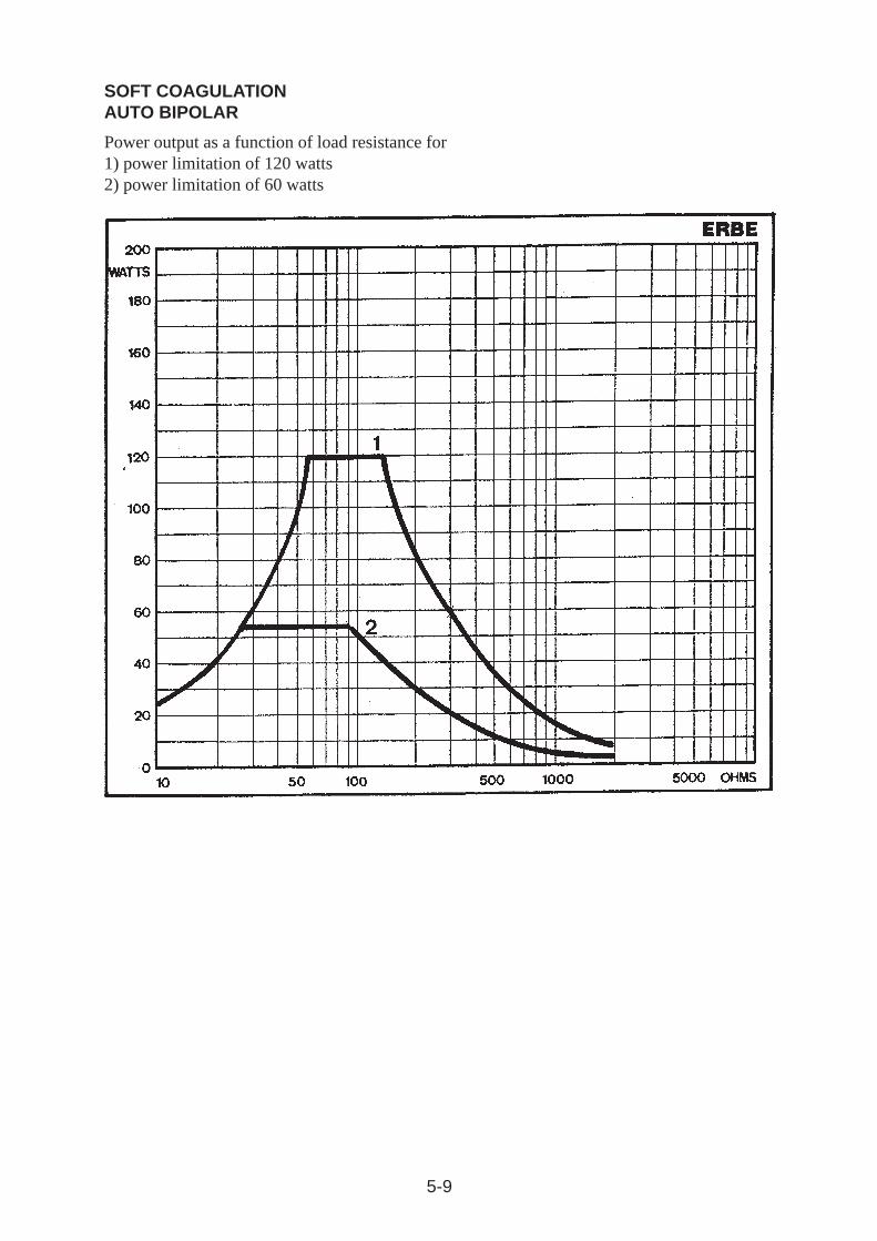
SOFT COAGULATIONAUTO BIPOLAR
Power output as a function of load resistance for1) power limitation of 120 watts2) power limitation of 60 watts
5-10
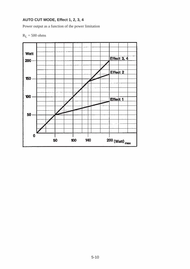
AUTO CUT MODE, Effect 1, 2, 3, 4
Power output as a function of the power limitation
RL = 500 ohms
5-11
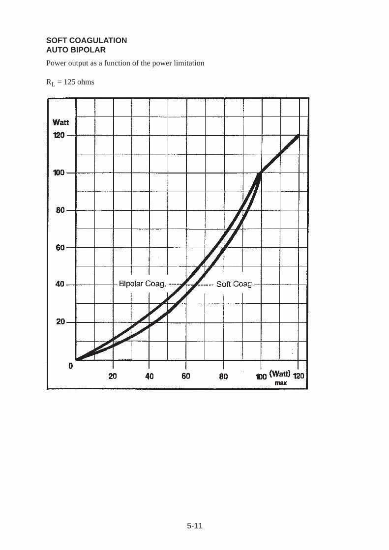
SOFT COAGULATIONAUTO BIPOLAR
Power output as a function of the power limitation
RL = 125 ohms
5-12
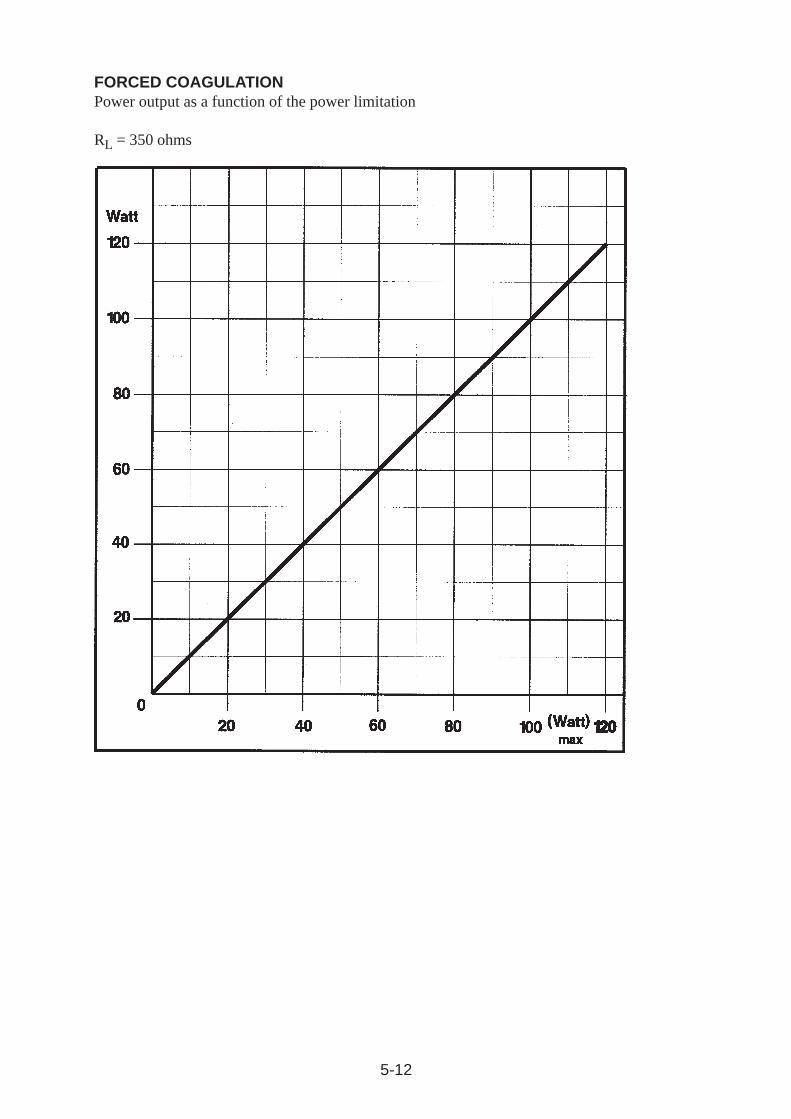
FORCED COAGULATIONPower output as a function of the power limitation
RL = 350 ohms
5-13
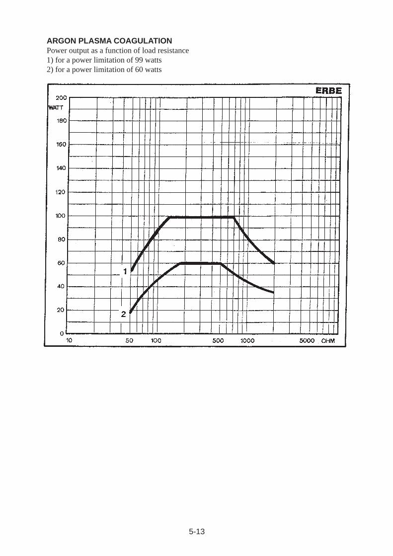
ARGON PLASMA COAGULATIONPower output as a function of load resistance1) for a power limitation of 99 watts2) for a power limitation of 60 watts
5-14
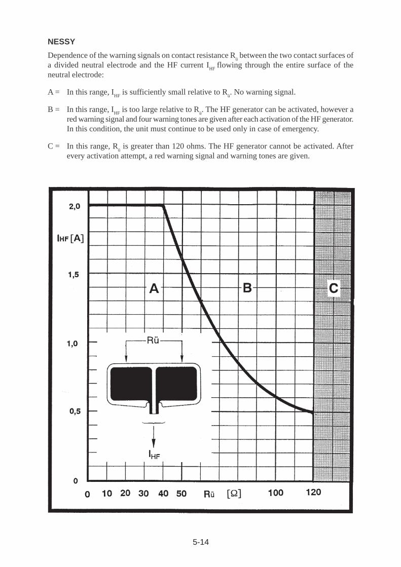
NESSY
Dependence of the warning signals on contact resistance Rü between the two contact surfaces of
a divided neutral electrode and the HF current IHF
flowing through the entire surface of theneutral electrode:
A = In this range, IHF
is sufficiently small relative to Rü. No warning signal.
B = In this range, IHF
is too large relative to Rü. The HF generator can be activated, however a
red warning signal and four warning tones are given after each activation of the HF generator.In this condition, the unit must continue to be used only in case of emergency.
C = In this range, Rü is greater than 120 ohms. The HF generator cannot be activated. After
every activation attempt, a red warning signal and warning tones are given.
6-1
6 INSTALLATION
6.1 Spatial requirementsHigh-frequency surgery units must only be operated in medically used rooms. The spatialrequirements, in regard to electric installation, affect e.g. the grounded conductor system, theground fault interrupt system, as well as measures for preventing electrostatic charges.
The unit is used in rooms in which personnel can pick up electrostatic charges, for example inrooms with electrically nonconductive floors, thus touching the front panel of the units can leadto a brief illumination of light diodes or seven-segment displays due to discharge of an electrostaticcharge. However, this occurrence does not change the settings on the front panel.
6.2 Set-up possibilities in the operating roomICC model series units can be set up in principle on tables, consoles on ceiling suspensions orwall- mounted arms, as well as on special equipment carts.
6.3 Power connectionHigh-frequency surgical units must only be connected via the power cord provided by the unitmanufacturer or one of equal quality equipped with the national test symbol to a correctly installedhospital grade power socket. Here, no outlet power socket or extension cord should be used ifpossible for reasons of safety. If their use is unavoidable, these must be equipped with a protectiveground in perfect working order. The power outlet must be secured with a fuse with at least 10 Arated current.
6.4 Potential equalizationIf necessary, the unit can be connected to the potential equalization of the room. This shouldprevent low-frequency electrode currents, e.g. low-frequency leakage currents in a defectiveprotective ground system, from endangering the patient.
ICC model series units are equipped with a potential equalization connector on the unit backpanel according to DIN 42 801. In this way, the units can be connected via a potential equalizationline to a potential equalization terminal at the set-up location.
6.5 Danger of explosionA potentially explosive atmosphere can result:
· From the release or dissipation of a potentially explosive mixture of anesthetics containingoxygen or nitrous oxide.
· From the use of combustible skin cleansing and disinfection substances.
The spatial extent of the danger zone is defined in the standard IEC 60 601-1 section 37.5. and inexplosion safety regulations.
WARNING!
HF surgical units generate electrical sparks, and are thus a potential source of ignition. Set up theHF surgical unit outside the danger area.
6-2
WARNING!
Footswitches are also potential sources of ignition. Due to their application, it is not always possibleto avoid setting them up in or near to the danger zone. Footswitches must therefore meet thespecial safety requirements of the "AP Class" in accordance with IEC 60 601-1 and be markedwith corresponding labels, if they are set up in the danger zone.
6.6 Protection against moistureICC model series high-frequency surgical units are protected against the penetration of moisture inaccordance with EN 60 601-2-2 . In spite of this, these units should not be set up in the vicinity ofhoses or containers which contain liquids. Liquids should not be placed above or even on the unit.Only those footswitches may be used which are watertight in accordance with EN 60 601-2-2Sec. 44.6 aa. Only those electrode handles with key switches must be used which conform to EN60 601-2-2, Sec. 44.6 bb.
6.7 CoolingICC model series units must be set up in such a way that free air circulation around their housingis ensured. For that reason, set-up in confined corners, shelves etc. is not permissible.
6.8 HF interferencesHigh-frequency surgical units intentionally generate high-frequency voltages and currents. It musttherefore be taken into consideration during set-up and operation that other electromedical equipmentmay be subjected to functional interference.
6.9 Combination with other unitsIf an ICC is to be operated in combination with other units, make certain that the correct functionsand the safety of the units are not impaired by this combination.
For combination of an ICC with an Argon Plasma Coagulation unit, the instruction manual forthe Argon Plasma Coagulation unit must also be precisely observed.
6.10 Receiving inspectionThe unit should be checked immediately upon receipt for shipping damage and be subjected toa performance test. In case of damage due to shipping, this must be immediately reported to theshipping agent and a damage report must be filled out to secure the claim for damagecompensation. This must include, in addition to the name and address of the recipient, the dateof receipt, type and serial number of the unit supplied, as well as a description of the damages.
The unit�s original packaging should be retained during the guarantee period so that the unit canbe returned in the original packaging if this becomes necessary.
6-3
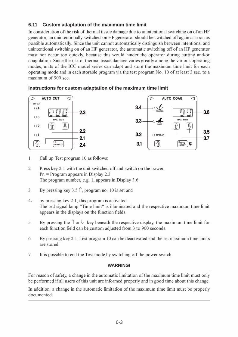
6.11 Custom adaptation of the maximum time limitIn consideration of the risk of thermal tissue damage due to unintentional switching on of an HFgenerator, an unintentionally switched-on HF generator should be switched off again as soon aspossible automatically. Since the unit cannot automatically distinguish between intentional andunintentional switching on of an HF generator, the automatic switching off of an HF generatormust not occur too quickly, because this would hinder the operator during cutting and/orcoagulation. Since the risk of thermal tissue damage varies greatly among the various operatingmodes, units of the ICC model series can adapt and store the maximum time limit for eachoperating mode and in each storable program via the test program No. 10 of at least 3 sec. to amaximum of 900 sec.
Instructions for custom adaptation of the maximum time limit
1. Call up Test program 10 as follows:
2. Press key 2.1 with the unit switched off and switch on the power.Pr. = Program appears in Display 2.3The program number, e.g. 1, appears in Display 3.6.
3. By pressing key 3.5 Ý, program no. 10 is set and
4. by pressing key 2.1, this program is activated.The red signal lamp �Time limit� is illuminated and the respective maximum time limitappears in the displays on the function fields.
5. By pressing the Ý or ß key beneath the respective display, the maximum time limit foreach function field can be custom adjusted from 3 to 900 seconds.
6. By pressing key 2.1, Test program 10 can be deactivated and the set maximum time limitsare stored.
7. It is possible to end the Test mode by switching off the power switch.
WARNING!
For reason of safety, a change in the automatic limitation of the maximum time limit must onlybe performed if all users of this unit are informed properly and in good time about this change.
In addition, a change in the automatic limitation of the maximum time limit must be properlydocumented.
6-4
6.12 Versions of Forced CoagulationFor Forced coagulation, the ICC generates brief voltage pulses with a high peak voltage. In thisway, an effective hemostasis is achieved even with very small-surface electrodes, such as withTUR resection loops or laparoscopic retractors. However, these voltage pulses can cause moreor less intensive disturbances in other electronic equipment, such as in video monitors. TheForced coagulation of the ICC can therefore be adapted via Test program 12 in regard to themaximum adjustable peak value of the voltage pulses according to the respective applicationpurpose.Three different versions of Forced coagulation are available for selection:
Version 1 (Standard version)
In this version, the peak value of the voltage pulses increases as a function of the power limitationin the range from 1 watt to 30 watts continuously to 1,300 V
p . Above 30 watts power limitation,
the peak value of the voltage pulses is limited to a maximum of approx. 1,300 Vp. This standard
version is set and stored on all units in the ICC 350 model series.
Version 2
In this version, the peak value of the voltage pulses continuously increases to 2,300 Vp as a
function of the power limitation in the range of 1 watt to 80 watts.
Version 3
In this version, the peak value of the voltage pulses increases continuously to 2,300 Vp as a
function of the power limitation in the range of 1 watt to 30 watts. Above 30 watts power limitation,the peak value of the voltage pulses is limited to a maximum of approx. 2,300 V
p.
WARNING!
If Version 2 or 3 is stored in memory, the unit briefly displays the current version every time afterthe power switch is switched on. Standard version 1 is not displayed.
In addition, any change of the version of Forced Coagulation must be properly documented.
6-5
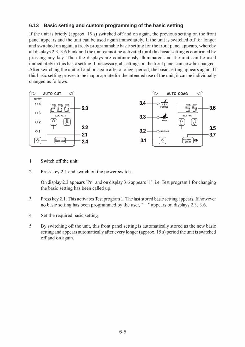
6.13 Basic setting and custom programming of the basic setting
If the unit is briefly (approx. 15 s) switched off and on again, the previous setting on the frontpanel appears and the unit can be used again immediately. If the unit is switched off for longerand switched on again, a freely programmable basic setting for the front panel appears, wherebyall displays 2.3, 3.6 blink and the unit cannot be activated until this basic setting is confirmed bypressing any key. Then the displays are continuously illuminated and the unit can be usedimmediately in this basic setting. If necessary, all settings on the front panel can now be changed.After switching the unit off and on again after a longer period, the basic setting appears again. Ifthis basic setting proves to be inappropriate for the intended use of the unit, it can be individuallychanged as follows.
1. Switch off the unit.
2. Press key 2.1 and switch on the power switch.
On display 2.3 appears �Pr� and on display 3.6 appears �1�, i.e. Test program 1 for changingthe basic setting has been called up.
3. Press key 2.1. This activates Test program 1. The last stored basic setting appears. If howeverno basic setting has been programmed by the user, ��� appears on displays 2.3, 3.6.
4. Set the required basic setting.
5. By switching off the unit, this front panel setting is automatically stored as the new basicsetting and appears automatically after every longer (approx. 15 s) period the unit is switchedoff and on again.
6-6
The unit is equipped with a specific front panel basic setting. The specific basic setting is definedat the factory and cannot be changed by the user. This specific basic setting only appears if thebasic setting freely programmable by the user is lost due to an error. For the ICC 200 unit, thefollowing specific basic setting is defined at the factory:
AUTO CUT EFFECT 3
AUTO CUT MAX.WATT 120 watts
ENDO CUT switched on
T-on time 50 ms
T-off time 750 ms
Monopolar SOFT COAG 60 watts
Monopolar FORCED COAG 60 watts
Monopolar ARGON COAG 60 watts
AUTO COAG BIPOLAR 40 watts, AUTO START switched off
7-1
7 CLEANING AND DISINFECTION OF THE UNIT
7.1 Cleaning and disinfection of the unitThe unit housing should only be cleaned and disinfected with nonflammable and nonexplosiveagents. Make certain here that no moisture penetrates into the unit.
We recommend a spray or wipe-down disinfection. However, the information from the disinfectantmanufacturer absolutely must be observed here.
WARNING!
If cleaning or disinfection of the unit with flammable or explosive agents unavoidable, this mustbe completely evaporated from the unit before switching on the unit.
Use no alcohol or disinfectant products with an alcohol base. The surface coating on the frontplate may become detached.

7-2
8-1
8 PERFORMANCE CHECKSBefore every application, the user should check the functional efficiency of the unit and theaccessories. The ICC is equipped for this with various automatic performance checks that, eachtime the power switch is switched on, are performed briefly and then signal and display recognizederrors. However, not all possible errors are automatically detected and displayed.
8.1 Automatic performance test after switching on the unitEach time the unit is switched on, it goes through an automatic performance check. If performanceerrors are detected here, these errors are signaled acoustically and an error number assigned tothe respective error is displayed. The following performance errors of the unit and of accessoriesconnected to the unit can be automatically recognized:
1. If a key on the front panel is depressed or shorted out due to an error once the power switchis switched on, this error is signaled acoustically after switching on the power switch andindicated by an error number.
2. If a key on the electrode handle is shorted out or bypassed at low resistance (e.g. due tomoisture in the electrode handle) due to an error or depressed while the power switch isswitched on, this error is signaled acoustically after the power switch is switched on andindicated by an error number.
3. If the contact of a footswitch is shorted out due to an error or if a pedal is stuck or a pedalis depressed while the power switch is switched on, this error is signaled acoustically andindicated by an error number.
8.2 Automatic performance check during activation
After every activation, the unit goes through an automatic performance check. If performanceerrors are determined here, these errors are acoustically signaled and an error number assignedto the respective error is displayed. The following performance errors of the unit and of accessoriesconnected to the unit are automatically recognized:
8.2.1 Check of the HF output voltageIf the HF output voltage deviates from the set HF output voltage when activating a certainoperating mode, e.g. CUTTING or SOFT COAGULATION, the unit produces acoustic warningsignals and displays this error with an error number (see Chapter 8.3 �Error list�).
8.2.2 Automatic check of the neutral electrodeIf the connection to the neutral electrode is interrupted during activation, or if the contact resistance(only for a divided neutral electrode) is too high, the unit switches the HF generator off, producesan acoustic warning signal and displays the error with an error number.
8-2
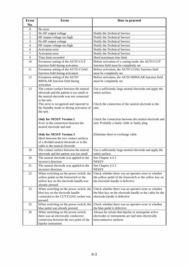
8.3 Automatic error documentation
Error numbers (ERROR No.) are assigned to the various errors recognized by the error recognitionsystem. If an error occurs, it is not only immediately reported visually and/or acoustically, butalso the corresponding error number is additionally stored in the unit, where it then also remainsstored when the unit is switched off. The last respective 10 error numbers can be called up at anytime as follows via Test program no. 2.
Calling up the test programs:
� In the AUTO CUT field, press the EFFECT key with the unit switched off andsimultaneously switch on the power switch.
� In the AUTO CUT display, Pr = Program appears,
� In the AUTO COAG display, 1 = Test number 1 appears.
� By pressing the Ý or ß key in the AUTO COAG field, the required test program number isselected.
� By pressing the EFFECT key in the AUTO CUT field, the required test program is started.
� End the test program by briefly switching off the power switch.
Calling up the stored ERROR numbers
� Call up Test program no. 2 (see above) and start.
� By pressing the Ý or ß key in the AUTO COAG field, memory locations 1 to 10 are calledup.
� In the AUTO CUT display, the number of the memory location appears.
� In the Auto COAG display, the error number appears.
� The cause of error corresponding to each error number is listed in the error list (see above).
� End this test program by briefly switching off the power switch.
8-3
ErrorNo.
Error How to proceed
0 No error1 No HF output voltage Notify the Technical Service2 HF output voltage too high Notify the Technical Service3 No HF output voltage Notify the Technical Service4 HF output voltage too high Notify the Technical Service6 Activation error Notify the Technical Service7 Activation error Notify the Technical Service9 Time limit exceeded Heed maximum time limit10 Erroneous setting of the AUTO CUT
function field during activationBefore activation of a cutting mode, the AUTO CUTfunction field must be completely set
11 Erroneous setting of the AUTO COAGfunction field during activation
Before activation, the AUTO COAG function fieldmust be completely set
12 Erroneous setting of the AUTOBIPOLAR function field duringactivation
Before activation, the AUTO BIPOLAR function fieldmust be completely set
13 The contact surface between the neutralelectrode and the patient is too small orthe neutral electrode was not connectedto the unit.This error is recognized and reported inthe Standby mode or during activation ofthe unit.
Only for NESSY Version 2Error in the connection between theneutral electrode and unit
Only for NESSY Version 3Short between the two contact surfacesof a divided neutral electrode or in thecable to the neutral electrode
Use a sufficiently large neutral electrode and apply theentire surface.
Check the connection of the neutral electrode to theunit.
Check the connection between the neutral electrode andunit. Probably a faulty cable or faulty plug
Eliminate short or exchange cable
19 The contact surface between the neutralelectrode and the patient was too small
Use a sufficiently large neutral electrode and apply theentire surface.
20 The neutral electrode was applied in theincorrect direction
See Chapter 4.3.3NESSY
21 The neutral electrode was applied in theincorrect direction
See Chapter 4.3.3NESSY
22 When switching on the power switch, theyellow pedal on the footswitch or theyellow key on the electrode handle wasalready pressed
Check whether there was an operator error or whetherthe yellow pedal of the footswitch or the yellow key onthe electrode handle is defective
23 When switching on the power switch, theblue key on the electrode handleconnected to the CUT/COAG socket waspressed
Check whether there was an operator error or whetherthe blue key on the electrode handle or the cable for theelectrode handle is defective
25 When switching on the power switch, theblue pedal was already pressed
Check whether there was an operator error or whetherthe blue pedal is defective
26 When switching on the power switch,there was an electrically conductiveconnection between the two poles of thebipolar instrument
Always be certain that bipolar or monopolar activeelectrodes or instruments are laid onto electricallynonconductive surfaces
8-4
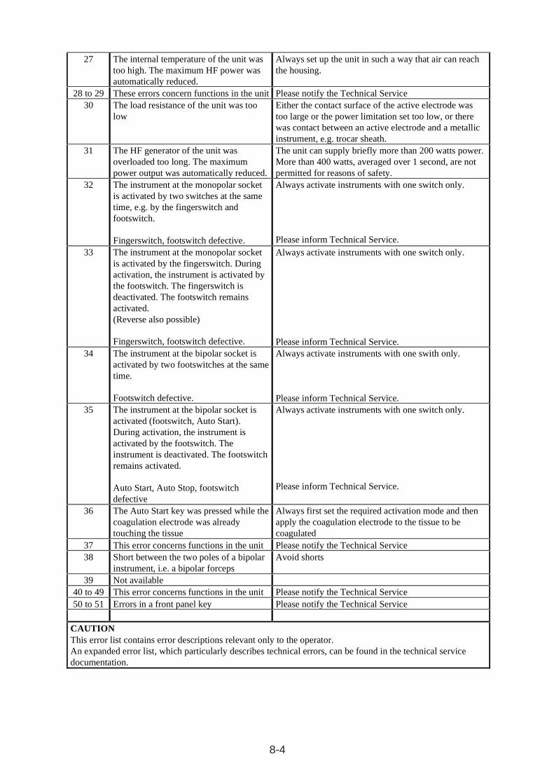
27 The internal temperature of the unit was too high. The maximum HF power was automatically reduced.
Always set up the unit in such a way that air can reach the housing.
28 to 29 These errors concern functions in the unit Please notify the Technical Service 30 The load resistance of the unit was too
low Either the contact surface of the active electrode was too large or the power limitation set too low, or there was contact between an active electrode and a metallic instrument, e.g. trocar sheath.
31 The HF generator of the unit was overloaded too long. The maximum power output was automatically reduced.
The unit can supply briefly more than 200 watts power. More than 400 watts, averaged over 1 second, are not permitted for reasons of safety.
32 The instrument at the monopolar socket is activated by two switches at the same time, e.g. by the fingerswitch and footswitch. Fingerswitch, footswitch defective.
Always activate instruments with one switch only.
Please inform Technical Service. 33 The instrument at the monopolar socket
is activated by the fingerswitch. During activation, the instrument is activated by the footswitch. The fingerswitch is deactivated. The footswitch remains activated. (Reverse also possible) Fingerswitch, footswitch defective.
Always activate instruments with one switch only.
Please inform Technical Service. 34 The instrument at the bipolar socket is
activated by two footswitches at the same time. Footswitch defective.
Always activate instruments with one swith only.
Please inform Technical Service. 35 The instrument at the bipolar socket is
activated (footswitch, Auto Start). During activation, the instrument is activated by the footswitch. The instrument is deactivated. The footswitch remains activated. Auto Start, Auto Stop, footswitch defective
Always activate instruments with one switch only.
Please inform Technical Service.
36 The Auto Start key was pressed while the coagulation electrode was already touching the tissue
Always first set the required activation mode and then apply the coagulation electrode to the tissue to be coagulated
37 This error concerns functions in the unit Please notify the Technical Service 38 Short between the two poles of a bipolar
instrument, i.e. a bipolar forceps Avoid shorts
39 Not available 40 to 49 This error concerns functions in the unit Please notify the Technical Service 50 to 51 Errors in a front panel key Please notify the Technical Service
CAUTION This error list contains error descriptions relevant only to the operator. An expanded error list, which particularly describes technical errors, can be found in the technical service documentation.
9-1
9 SAFETY CHECKS
To prevent a reduction in safety for the unit due to age, wear etc., § 6 of the regulation concerningthe installation, operation and use of active medical products (BetreibVaMP) prescribes regularsafety checks. The operator must have the safety checks which have been established for thisunit properly performed to the prescribed extent.
The following safety checks have been established for the ICC :
• Inspection of inscriptions and instruction manual
• Visual inspection of the unit and accessories for damage
• Inspection for electrical safety according to EN 60 601-1.a) Grounded conductor inspectionb) Leakage current inspection
• Performance test of all switches and control lamps on the unit
• Inspection of the monitoring devices
• Inspection of the automatic start mode
• Measurement of power output in the CUT operating mode.
• Measurement of power output in the COAGULATE operating mode.
• Measurement of the high-frequency capacities in the various operating modes
• The high-frequency surgical unit must undergo a safety check at least once a year.
The results of these safety checks must be entered in the medical product logbook.
If deficiencies are found during the safety checks, by which patients, employees or third partiescould be endangered, the unit must not be operated until these deficiencies have been rectifiedby a professional technical service.

9-2
10-1
10 MAINTENANCE, CARE AND DISPOSAL OF THE UNIT
10.1 Maintenance of the unit including reusable accessoriesMaintenance of the unit including the reusable accessories includes preventive and correctivemeasures for servicing. Therefore established, regularly performed safety checks (see Chapter9) represent preventive measures, while changes and repairs can be summarized under the categoryof corrective maintenance. Through regular maintenance, the unit including the reusableaccessories should be kept within the required status specified in the technical data, and operationalreadiness and safety are guaranteed for this until the next maintenance date.
10.1.1 Changes and repairsChanges and repairs must not reduce the safety of the unit and its accessories for the patient, theuser and the surroundings. This is considered fulfilled if structural and functional features havenot been changed at the expense of safety (DIN 57 751-1/VDE 0751-1). Changes and repairs tothe unit, in consideration of the special safety requirements for high-frequency surgical units,must only be performed by the manufacturer or by persons expressly authorized to do this byhim. If unauthorized persons perform improper changes or repairs to the unit or accessories, themanufacturer assumes no liability. Additionally in this case, the guarantee claim becomes void.
10.2 Care of the unitEffective protection of the unit from damage also includes, in addition to proper operation andmaintenance, the safe set-up of the unit. This also includes, in addition to safe fixation of the unitto its base, its protection from moisture, contamination and contact with flammable or explosivesubstances. To ensure good radiation of unit heat resulting from operation, air circulation aroundthe cooling fans and the heat sink must not be impeded.
10.3 Disposal of the unitThe unit can be disposed of at the end of its useful life as standard electronic scrap.

10-2
11-1
11 CONDITIONS OF GUARANTEE
11.1 Customer serviceIf you are interested in a service contract, please contact ERBE Elektromedizin or an authorizedretailer. Do you have questions regarding high-frequency surgery, the ICC or on this instructionmanual? Wish you like the latest scientific publications on high-frequency surgery? Please contactan ERBE employee or your local branch office. We would be glad to help you.
11.2 Conditions of guaranteeThe unit and accessories must be immediately examined upon receipt for defects and shippingdamage. Claims for damage compensation in this regard are only considered valid if the Selleror Shipping agent is immediately notified. A damage report must be filled out.
The term of guarantee for the ICC is 3 years, for accessory parts 6 months, calculated from thedate of delivery. A claim of guarantee can only be made when the properly completed guaranteecertificate is presented.
The scope of the guarantee encompasses no-cost repair of the unit, provided the damage wascaused by a material or manufacturing error. Other claims, particularly claims of damagecompensation, are excluded.
Repair must only be performed by ERBE, one of our representatives, or by an authorized retailer.The claim of guarantee becomes void if improper changes or repairs were made.
Through guarantee performances, the guarantee is neither extended nor renewed.

11-2
12-1
12 INFORMATION ON ELECTROMAGNETIC COMPATIBILITY(EMC)
Where EMC is concerned, medical electrical equipment is subject to special safety measuresand must be installed and commissioned according to the EMC instructions stated herein.
Guidelines for avoiding, recognizing, and rectifying unwanted electromagneticeffects on other equipment or systems that are the result of operating the ICCelectrosurgical unit.When ICC electrosurgical units are activated, disturbance of other equipment or sys-tems in theimmediate vicinity can occur. This can be recognized as, for example, image artifacts in imagingdevices or unusual fluctuations in measured value dis-plays.
Such disturbances from an activated electrosurgical unit can be reduced by placing it further awayand/or carrying out suitable shielding measures on the equipment or system experiencingdisturbance.
When the ICC electrosurgical unit is in the non-activated state, interference with other equipmentin the immediate vicinity does not occur.
ATTENTION
The use of internal cables other than those specified in the Service Manual may result in increasedemissions or decreased immunity of the equipment.
ATTENTION
The equipment should not be used adjacent to or stacked with equipment, other than with thatwhich is intended for this purpose. If adjacent or stacked use is necessary, the entire systemshould be observed to verify normal operation in the configuration in which it will be used.
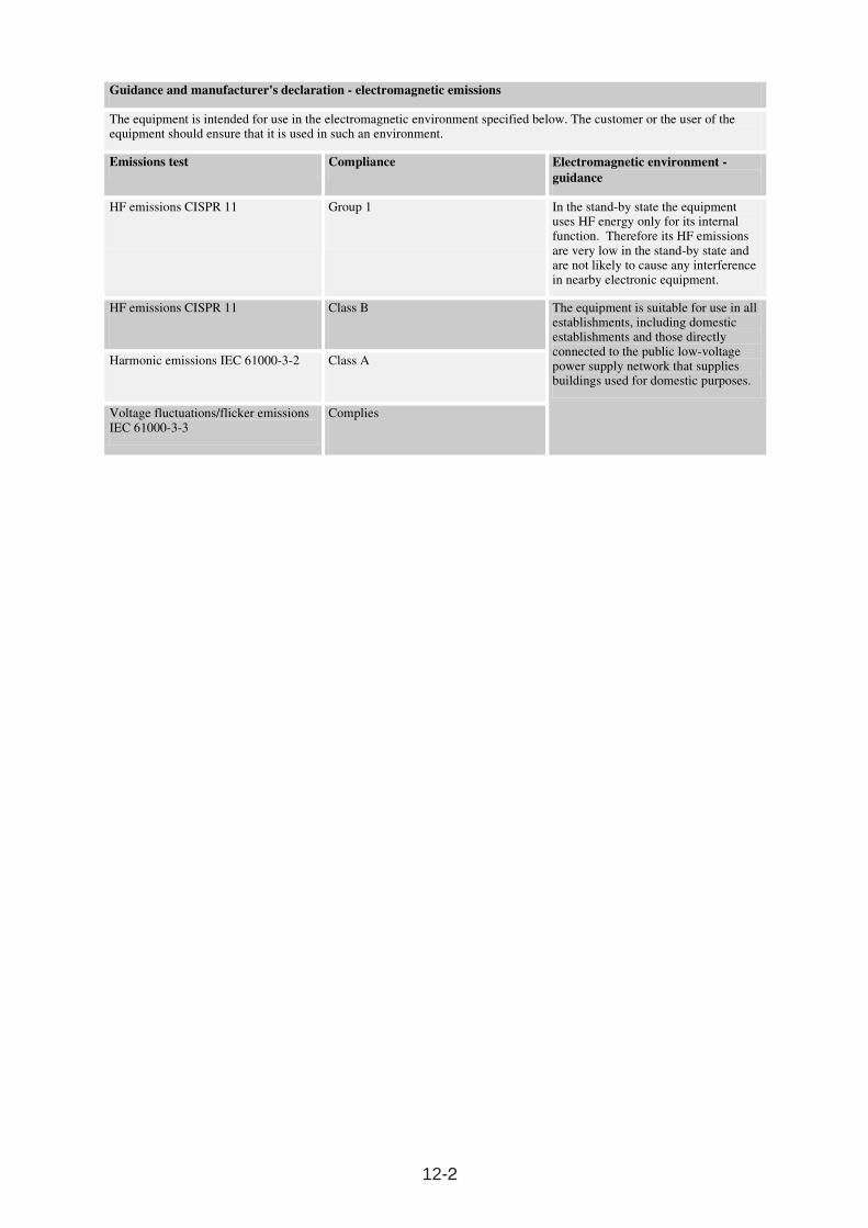
12-2
Guidance and manufacturer's declaration - electromagnetic emissions
The equipment is intended for use in the electromagnetic environment specified below. The customer or the user of the equipment should ensure that it is used in such an environment.
Emissions test Compliance Electromagnetic environment -guidance
HF emissions CISPR 11 Group 1 In the stand-by state the equipment uses HF energy only for its internal function. Therefore its HF emissions are very low in the stand-by state and are not likely to cause any interference in nearby electronic equipment.
HF emissions CISPR 11 Class B
Harmonic emissions IEC 61000-3-2 Class A
Voltage fluctuations/flicker emissions IEC 61000-3-3
Complies
The equipment is suitable for use in all establishments, including domestic establishments and those directly connected to the public low-voltage power supply network that supplies buildings used for domestic purposes.
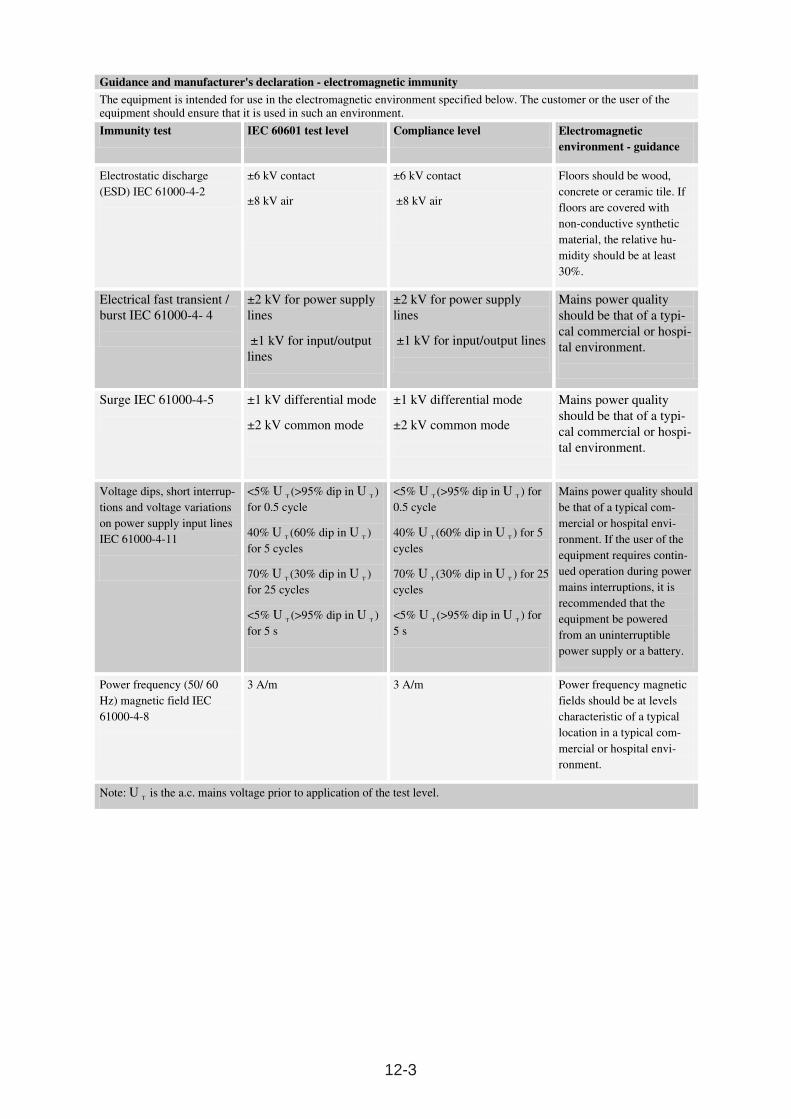
12-3
Guidance and manufacturer's declaration - electromagnetic immunity
The equipment is intended for use in the electromagnetic environment specified below. The customer or the user of the equipment should ensure that it is used in such an environment.
Immunity test IEC 60601 test level Compliance level Electromagnetic environment - guidance
Electrostatic discharge (ESD) IEC 61000-4-2
±6 kV contact
±8 kV air
±6 kV contact
±8 kV air
Floors should be wood, concrete or ceramic tile. If floors are covered with non-conductive synthetic material, the relative hu-midity should be at least 30%.
Electrical fast transient / burst IEC 61000-4- 4
±2 kV for power supply lines
±1 kV for input/output lines
±2 kV for power supply lines
±1 kV for input/output lines
Mains power quality should be that of a typi-cal commercial or hospi-tal environment.
Surge IEC 61000-4-5 ±1 kV differential mode
±2 kV common mode
±1 kV differential mode
±2 kV common mode
Mains power quality should be that of a typi-cal commercial or hospi-tal environment.
Voltage dips, short interrup-tions and voltage variations on power supply input lines IEC 61000-4-11
<5% U T (>95% dip in U T ) for 0.5 cycle
40% U T (60% dip in U T ) for 5 cycles
70% U T (30% dip in U T ) for 25 cycles
<5% UT (>95% dip in U
T )
for 5 s
<5% U T (>95% dip in U T ) for 0.5 cycle
40% U T (60% dip in U T ) for 5 cycles
70% U T (30% dip in U T ) for 25 cycles
<5% UT (>95% dip in U
T ) for
5 s
Mains power quality should be that of a typical com-mercial or hospital envi-ronment. If the user of the equipment requires contin-ued operation during power mains interruptions, it is recommended that the equipment be powered from an uninterruptible power supply or a battery.
Power frequency (50/ 60 Hz) magnetic field IEC 61000-4-8
3 A/m 3 A/m Power frequency magnetic fields should be at levels characteristic of a typical location in a typical com-mercial or hospital envi-ronment.
Note: UT is the a.c. mains voltage prior to application of the test level.
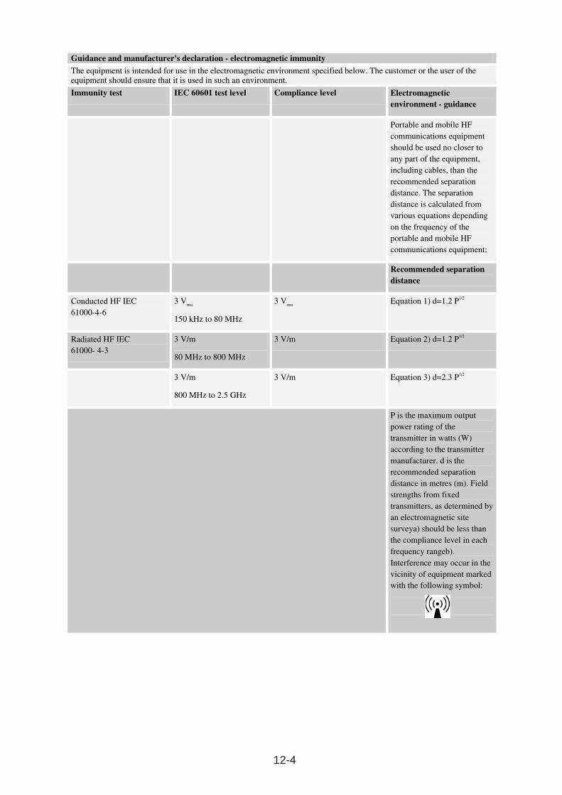
12-4
Guidance and manufacturer's declaration - electromagnetic immunity
The equipment is intended for use in the electromagnetic environment specified below. The customer or the user of the equipment should ensure that it is used in such an environment.
Immunity test IEC 60601 test level Compliance level Electromagnetic environment - guidance
Portable and mobile HF communications equipment should be used no closer to any part of the equipment, including cables, than the recommended separation distance. The separation distance is calculated from various equations depending on the frequency of the portable and mobile HF communications equipment:
Recommended separation distance
Conducted HF IEC 61000-4-6
3 Vrms
150 kHz to 80 MHz
3 Vrms
Equation 1) d=1.2 P1/2
Radiated HF IEC 61000- 4-3
3 V/m
80 MHz to 800 MHz
3 V/m Equation 2) d=1.2 P1/2
3 V/m
800 MHz to 2.5 GHz
3 V/m Equation 3) d=2.3 P1/2
P is the maximum output power rating of the transmitter in watts (W) according to the transmitter manufacturer. d is the recommended separation distance in metres (m). Field strengths from fixed transmitters, as determined by an electromagnetic site surveya) should be less than the compliance level in each frequency rangeb). Interference may occur in the vicinity of equipment marked with the following symbol:
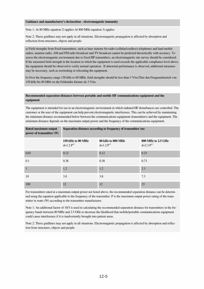
12-5
Guidance and manufacturer's declaration - electromagnetic immunity
Note 1: At 80 MHz equation 2) applies At 800 MHz equation 3) applies
Note 2: These guidlines may not apply in all situations. Electromagnetic propagation is affected by absorption and reflection from structures, objects and people.
a) Field strengths from fixed transmitters, such as base stations for radio (cellular/cordless) telephones and land mobile radios, amateur radio, AM and FM radio broadcast and TV broadcast cannot be predicted theoretically with accuracy. To assess the electromagnetic environment due to fixed HF transmitters, an electromagnetic site survey should be considered. If the measured field strength in the location in which the equipment is used exceeds the applicable compliance level above, the equipment should be observed to verify normal operation. If abnormal performance is observed, additional measures may be necessary, such as reorienting or relocating the equipment.
b) Over the frequency range 150 kHz to 80 MHz, field strengths should be less than 3 V/m.Über den Frequenzbereich von 150 kHz bis 80 MHz ist die Feldstärke kleiner als 3 V/m.
Recommended separation distances between portable and mobile HF communications equipment and the equipment
The equipment is intended for use in an electromagnetic environment in which radiated HF disturbances are controlled. The customer or the user of the equipment can help prevent electromagnetic interference. This can be achieved by maintaining the minimum distance recommended below between the communications equipment (transmitters) and the equipment. The minimum distance depends on the maximum output power and the frequency of the communications equipment.
Rated maximum output power of transmitter (W)
Separation distance according to frequency of transmitter (m)
150 kHz to 80 MHzd=1.2 P1/2
80 kHz to 800 MHzd=1.2 P1/2
800 MHz to 2.5 GHzd=2.3 P1/2
0.01 0.12 0.12 0.23
0.1 0.38 0.38 0.73
1 1.2 1.2 2.3
10 3.8 3.8 7.3
100 12 12 23
For transmitters rated at a maximum output power not listed above, the recommended separation distance can be determi-ned using the equation applicable to the frequency of the transmitter. P is the maximum output power rating of the trans-mitter in watts (W) according to the transmitter manufacturer.
Note 1: An additional factor of 10/3 is used in calculating the recommended separation distance for transmitters in the fre-quency bands between 80 MHz and 2.5 GHz to decrease the likelihood that mobile/portable communications equipment could cause interference if it is inadvertently brought into patient areas.
Note 2: These guidlines may not apply in all situations. Electromagnetic propagation is affected by absorption and reflec-tion from structures, objects and people.

12-6


![Hybrid technology - ERBE Elektromedizin GmbH€¦ · [electrosurgery] technology for ablation with controlled cutting and coagulation technique. The HybridKnife® enables submucosal](https://img.pdfslide.us/doc/110x75/5fa0a2b90917f561bc2e3c8a/hybrid-technology-erbe-elektromedizin-gmbh-electrosurgery-technology-for-ablation.jpg)