Embed Size (px)
Citation preview

8/18/2019 UTRAN Physical Layer Procedures (FDD)
http://slidepdf.com/reader/full/utran-physical-layer-procedures-fdd 1/99
3GPP TS 25.214 V9.4.0 (2010-12)
Technical Specification
3rd Generation Partnership Project;Technical Specification Group Radio Access Network;
Physical layer procedures (F!(Release "!
The present document has been developed within the 3rd Generation Partnership Project (3GPP TM) and may be further elaborated for the purposes of 3GPP.
The present document has not been subject to any approval process by the 3GPP Oranisational Partners and shall not be implemented.
This !pecification is provided for future development wor" within 3GPP only. The Oranisational Partners accept no liability for any use of this
!pecification.!pecifications and reports for implementation of the 3GPP TM system should be obtained via the 3GPP Oranisational Partners# Publications Offices.

8/18/2019 UTRAN Physical Layer Procedures (FDD)
http://slidepdf.com/reader/full/utran-physical-layer-procedures-fdd 2/993GPP
$eywordsUMTS, radio, layer 1
3GPP
Postal address
3GPP support office address
650 Roue de! "u#iole! - So$%ia &'i$oli!Valo''e - R&*+
Tel. 33 4 92 94 42 00 a/ 33 4 93 65 4 16
%nternet
%$.3$$.or
Copyright Notification
&o part may be reproduced e'cept as authoried by written permission.The copyriht and the foreoin restriction e'tend to reproduction in all media.
*+,+- 3GPP Oraniational Partners (/%0- T%!- 11!- 2T!%- TT- TT1).ll rihts reserved.
MT!4 is a Trade Mar" of 2T!% reistered for the benefit of its members
3GPP4 is a Trade Mar" of 2T!% reistered for the benefit of its Members and of the 3GPP Oraniational Partners
5T24 is a Trade Mar" of 2T!% currently bein reistered for the benefit of its Members and of the 3GPPOraniational Partners
G!M6 and the G!M loo are reistered and owned by the G!M ssociation
RAFT3GPP TS #$%#&' "%'%) (#)&)*&#!#Release "

8/18/2019 UTRAN Physical Layer Procedures (FDD)
http://slidepdf.com/reader/full/utran-physical-layer-procedures-fdd 3/99
+o'e'!
7oreword..........................................................................................................................................................
, !cope......................................................................................................................................................
* /eferences..............................................................................................................................................
3 8efinitions and bbreviations................................................................................................................3., 8efinitions...........................................................................................................................................................3.* bbreviations.......................................................................................................................................................
9 !ynchronisation procedures....................................................................................................................9., 1ell search...........................................................................................................................................................9.* 1ommon physical channel synchronisation........................................................................................................9.*., P:11P1; radio frame timin........................................................................................................................9.*.* !:11P1; soft combinin timin..................................................................................................................9.*.3 /adio frame timin on the M0!7& layer......................................................................................................
9.*.9 !econdary servin ;!:8!1; cell timin......................................................................................................9.3 8P11;<8P81;<7:8P1; synchronisation........................................................................................................9.3., !ynchronisation primitives............................................................................................................................9.3.,., General.....................................................................................................................................................9.3.,.* 8ownlin" synchronisation primitives....................................................................................................9.3.,.3 plin" synchronisation primitives.........................................................................................................
9.3.* /adio lin" establishment and physical layer reconfiuration for dedicated channels.................................9.3.*., General...................................................................................................................................................9.3.*.* &ode 0 radio lin" set state machine.......................................................................................................9.3.*.3 !ynchronisation procedure .................................................................................................................9.3.*.3 !ynchronisation procedure ..............................................................................................................9.3.*.9 !ynchronisation procedure 0.................................................................................................................
9.3.3 /adio lin" monitorin..................................................................................................................................
9.3.3., 8ownlin" radio lin" failure....................................................................................................................9.3.3.* plin" radio lin" failure<restore in 1255=81; state...........................................................................9.3.3.* plin" radio lin" failure<restore in 1255=71; state and %852 mode..............................................9.3.9 Transmission timin adjustments.................................................................................................................
> Power control.......................................................................................................................................>., plin" power control.........................................................................................................................................
>.,., P/1;........................................................................................................................................................>.,.,., General...................................................................................................................................................>.,.,.* !ettin of P/1; control and data part power difference....................................................................>.,.* 8P11;<8P81;..........................................................................................................................................>.,.*., General...................................................................................................................................................>.,.*.* Ordinary transmit power control............................................................................................................
>.,.*.*., General..............................................................................................................................................>.,.*.*.* lorithm , for processin TP1 commands....................................................................................>.,.*.*.3 lorithm * for processin TP1 commands....................................................................................>.,.*.3 Transmit power control in compressed mode........................................................................................>.,.*.9 Transmit power control in the uplin" 8P11; power control preamble................................................>.,.*.> !ettin of the uplin" 8P11;<8P81; relative powers.........................................................................
>.,.*.>., General..............................................................................................................................................>.,.*.>.* !inalled ain factors.......................................................................................................................>.,.*.>.3 1omputed ain factors......................................................................................................................>.,.*.>.9 !ettin of the uplin" 8P11;<8P81; relative powers in compressed mode.................................>.,.*.> !ettin of the uplin" ;!:8P11; power relative to 8P11; power.....................................................>.,.*.>0 !ettin of the uplin" 2:8P11; and 2:8P81; powers relative to 8P11; power.............................
>.,.*.>0., 2:8P11;<8P11;...........................................................................................................................
>.,.*.>0.* 2:8P81;<8P11;..........................................................................................................................>.,.*.>1 !ettin of the uplin" 8P11; ain factor when no 8P81; is confiured...........................................>.,.*.? Ma'imum and minimum power limits...................................................................................................>.,.3 @oid..............................................................................................................................................................
3GPP
RAFT3GPP TS #$%#&' "%'%) (#)&)*&#!3Release "

8/18/2019 UTRAN Physical Layer Procedures (FDD)
http://slidepdf.com/reader/full/utran-physical-layer-procedures-fdd 4/99
>.* 8ownlin" power control....................................................................................................................................>.*., 8P11;<8P81;<7:8P1;..........................................................................................................................>.*.,., General...................................................................................................................................................>.*.,.* Ordinary transmit power control............................................................................................................
>.*.,.*., 2 behaviour....................................................................................................................................>.*.,.*.* T/& behaviour...........................................................................................................................
>.*.,.3 Power control in compressed mode.......................................................................................................>.*.,.9 @oid........................................................................................................................................................>.*.* @oid..............................................................................................................................................................>.*.3 @oid..............................................................................................................................................................
>.*.9 %1;............................................................................................................................................................>.*.> P%1;............................................................................................................................................................>.*.? !:11P1;.....................................................................................................................................................>.*.A @oid..............................................................................................................................................................>.*.B @oid..............................................................................................................................................................>.*.C @oid..............................................................................................................................................................
>.*.,+ ;!:!11;.....................................................................................................................................................>.*.,, ;!:P8!1;..................................................................................................................................................>.*.,* 2:G1;......................................................................................................................................................
>.*.,3 2:;%1;........................................................................................................................................................>.*.,9 2:/G1;.......................................................................................................................................................
>.*.,> M%1;...........................................................................................................................................................>.*.,? !:1P%1;......................................................................................................................................................
? /andom access procedure.....................................................................................................................?., Physical random access procedure....................................................................................................................?.,., /1; sub:channels.....................................................................................................................................?.,.* /1; access slot sets................................................................................................................. .......... ......?., Physical random access procedure for 2nhanced plin" in 1255=71; state and %852 mode...................?.* @oid....................................................................................................................................................................
? ;!:8!1;:related procedures...............................................................................................................?., General procedure..............................................................................................................................................
?.,., 2 procedure for receivin ;!:8!1; and ;!:!11; in the 1255=81; state.......................................?.,., 2 procedure for receivin ;!:8!1; and ;!:!11; in 1255=71; state...........................................?.,.,0 2 procedure for receivin ;!:8!1; and ;!:!11; in the /=P1; and 1255=P1; states............?.,.* 2 procedure for reportin channel Duality indication (1E%) and precodin control indication (P1%)
......................................................................................................................................................................?.,.*., 1E% reportin procedure in case the 2 is not confiured in M%MO mode..........................................
?.,.*.* 1omposite P1%<1E% reportin procedure in case the 2 is confiured in M%MO mode......................?.,.3 &ode 0 procedure for transmittin the ;!:8!1; and ;!:!11;..............................................................?.,.3., &ode 0 procedure for transmittin the ;!:8!1; and ;!:!11; in the 1255=81; state................?.,.3.* &ode 0 procedure for transmittin the ;!:8!1; and ;!:!11; in the 1255=71; state..............?.,.3.3 &ode 0 procedure for transmittin the ;!:8!1; and ;!:!11; in the /=P1; or
1255=P1; state....................................................................................................................................
?.* 1hannel Duality indicator (1E%) definition........................................................................................................
?.*., 1E% definition when the 2 is not confiured in M%MO mode..................................................................?.*.* 1E% definition when the 2 is confiured in M%MO mode........................................................................?.*.3 1E% tables.......................................................................................................................................... ......... .?.3 Operation durin compressed mode on the associated 8P1; or 7:8P1;......................................................?.9 Precodin control indication (P1%) definition...................................................................................................
?0 2:81; related procedures....................................................................................................................?0., 1$<&1$ detection.......................................................................................................................................
?0.* /elative rants detection....................................................................................................................................?0.3 2:81; control timin.......................................................................................................................................?0.3., ,+ ms 2:81; TT%........................................................................................................................................?0.3.* * ms 2:81; TT%..........................................................................................................................................?0.9 Operation durin compressed mode..................................................................................................................
?0.9., plin" compressed mode.............................................................................................................................?0.9.* 8ownlin" compressed mode........................................................................................................................
3GPP
RAFT3GPP TS #$%#&' "%'%) (#)&)*&#!'Release "

8/18/2019 UTRAN Physical Layer Procedures (FDD)
http://slidepdf.com/reader/full/utran-physical-layer-procedures-fdd 5/99
?1 8iscontinuous transmission and reception procedures..........................................................................?1., plin" 1E% transmission...................................................................................................................................?1.* 8iscontinuous uplin" 8P11; transmission operation.....................................................................................
?1.*., plin" 8P11; burst pattern.......................................................................................................................?1.*.* plin" 8P11; preamble and postamble....................................................................................................?1.*.*., plin" 8P11; preamble and postamble for the 8P11; only transmission.......................................
?1.*.*.* plin" 8P11; preamble and postamble for the 2:81; transmission................................................?1.*.*.3 plin" 8P11; preamble and postamble for the ;!:8P11; transmission.........................................?1.3 8iscontinuous downlin" reception....................................................................................................................
?1.9 ;!:!11; orders...............................................................................................................................................?1.> Operation durin compressed mode..................................................................................................................
A 1losed loop mode , transmit diversity.................................................................................................A., General procedure..............................................................................................................................................A.* 8etermination of feedbac" information.............................................................................................................A.*., 2nd of frame adjustment..............................................................................................................................A.*.* &ormal initialisation....................................................................................................................................
A.*.3 Operation durin compressed mode............................................................................................................A.*.3., 8ownlin" in compressed mode and uplin" in normal mode..................................................................
A.*.3.* 0oth downlin" and uplin" in compressed mode....................................................................................A.*.3.3 plin" in compressed mode and downlin" in normal mode..................................................................A.*.9 %nitialisation durin compressed mode........................................................................................................A.*.9., 8ownlin" in compressed mode..............................................................................................................
A.*.9.* plin" in compressed mode...................................................................................................................A.3 @oid....................................................................................................................................................................
B %dle periods for %P85 location method.................................................................................................B., General...............................................................................................................................................................B.* Parameters of %P85...........................................................................................................................................B.3 1alculation of idle period position....................................................................................................................
C M%MO operation of ;!:8!1;.............................................................................................................C., General procedure..............................................................................................................................................
Annex A (informative): (no title).........................................................................................................., ntenna verification...........................................................................................................................................* 1omputation of feedbac" information for closed loop mode , transmit diversity............................................
Annex B (Informative): Power control................................................................................................
0., 8ownlin" power control timin............................................................................................................
0.* 2'ample of implementation in the 2..................................................................................................
0.3 5 power control when losin 5 synchronisation..............................................................................
Annex C (Informative): Cell search procedure...................................................................................
Annex D (informative): Change histor..............................................................................................
3GPP
RAFT3GPP TS #$%#&' "%'%) (#)&)*&#!$Release "

8/18/2019 UTRAN Physical Layer Procedures (FDD)
http://slidepdf.com/reader/full/utran-physical-layer-procedures-fdd 6/99
oreord
This Technical !pecification (T!) has been produced by the 3rd Generation Partnership Project (3GPP).
The contents of the present document are subject to continuin wor" within the T!G and may chane followin formalT!G approval. !hould the T!G modify the contents of this present document- it will be re:released by the T!G with anidentifyin chane of release date and an increase in version number as followsF
@ersion '.y.
whereF
' the first diitF
, presented to T!G for information
* presented to T!G for approval
3 or reater indicates T!G approved document under chane control.
y the second diit is incremented for all chanes of substance- i.e. technical enhancements- corrections-updates- etc.
the third diit is incremented when editorial only chanes have been incorporated in the document.
3GPP
RAFT3GPP TS #$%#&' "%'%) (#)&)*&#!+Release "

8/18/2019 UTRAN Physical Layer Procedures (FDD)
http://slidepdf.com/reader/full/utran-physical-layer-procedures-fdd 7/99
1 S#o$e
The present document specifies and establishes the characteristics of the physicals layer procedures in the 788 mode of T/.
2 Reere'#e!
The followin documents contain provisions which- throuh reference in this te't- constitute provisions of the presentdocument.
• /eferences are either specific (identified by date of publication- edition number- version number- etc.) or
non:specific.
• 7or a specific reference- subseDuent revisions do not apply.
• 7or a non:specific reference- the latest version applies. %n the case of a reference to a 3GPP document (includin
a G!M document)- a non:specific reference implicitly refers to the latest version of that document in the same
Release as the present document .
H,I 3GPP T! *>.*,,F JPhysical channels and mappin of transport channels onto physical channels(788)J.
H*I 3GPP T! *>.*,*F JMultiple'in and channel codin (788)J.
H3I 3GPP T! *>.*,3F J!preadin and modulation (788)J.
H9I 3GPP T! *>.*,>F JPhysical layer K Measurements (788)J.
H>I 3GPP T! *>.33,F J//1 Protocol !pecificationJ.
H?I 3GPP T! *>.933F JT/& %ub %nterface &0P !inallinJ.
HAI 3GPP T! *>.,+,F J2 /adio transmission and /eception (788)J.
HBI 3GPP T! *>.,33F J/eDuirements for !upport of /adio /esource Manaement (788)J.
HCI 3GPP T! *>.3*,F JM1 protocol specificationJ.
H,+I 3GPP T! *>.3+?F J2 /adio ccess 1apabilitiesJ.
3 ei'iio'! a'd &reiaio'!
3.1 ei'iio'!
7or the purposes of the present document- the followin terms and definitions applyF
Activated uplin! fre"uenc: 7or a specific 2- an uplin" freDuency is said to be activated if the 2 is allowed totransmit on that freDuency. The primary uplin" freDuency is always activated when confiured while a secondary uplin"
freDuency has to be activated by means of an ;!:!11; order in order to become activated. !imilarly- for a specific 2-an uplin" freDuency is said to be deactivated if it is confiured but disallowed by the &ode0 to transmit on thatfreDuency.
Configured uplin! fre"uencF 7or a specific 2- an uplin" freDuency is said to be confiured if the 2 has receivedall relevant information from hiher layers in order to perform transmission on that freDuency.
3GPP
RAFT3GPP TS #$%#&' "%'%) (#)&)*&#!,Release "

8/18/2019 UTRAN Physical Layer Procedures (FDD)
http://slidepdf.com/reader/full/utran-physical-layer-procedures-fdd 8/99
#$ com%ining periodF n interval of contiuous TT%s when !:11P1;s- each on different /5s- may be soft combined.
Primar uplin! fre"uenc: %f a sinle uplin" freDuency is confiured for the 2- then it is the primary uplin"
freDuency. %n case more than one uplin" freDuency is confiured for the 2- then the primary uplin" freDuency is thefreDuency on which the 2:81; correspondin to the servin 2:81; cell associated with the servin ;!:8!1; cell istransmitted. The association between a pair of uplin" and downlin" freDuencies is indicated by hiher layers.
&econdar uplin! fre"uenc: secondary uplin" freDuency is a freDuency on which an 2:81; correspondin to aservin 2:81; cell associated with a secondary servin ;!:8!1; cell is transmitted. The association between a pair
of uplin" and downlin" freDuencies is indicated by hiher layers.
3.2 &reiaio'!
7or the purposes of the present document- the followin abbreviations applyF
1$ c"nowledement%1; cDuisition %ndicator 1hannel
!1 ccess !ervice 1lass01; 0roadcast 1hannel
11P1; 1ommon 1ontrol Physical 1hannel11Tr1; 1oded 1omposite Transport 1hannel1P%1; 1ommon Pilot 1hannel1E% 1hannel Euality %ndicator
1/1 1yclic /edundancy 1hec" 81; 8edicated 1hannel85 8ownlin" 8P11; 8edicated Physical 1ontrol 1hannel8P1; 8edicated Physical 1hannel8P81; 8edicated Physical 8ata 1hannel
8TL 8iscontinuous Transmission2:81; 2nhanced 8edicated 1hannel2:8P11; 2:81; 8edicated Physical 1ontrol 1hannel
2:8P81; 2:81; 8edicated Physical 8ata 1hannel2:G1; 2:81; bsolute Grant 1hannel2:;%1; 2:81; ;/E c"nowledement %ndicator 1hannel
2:/G1; 2:81; /elative Grant 1hannel7:8P1; 7ractional 8edicated Physical 1hannel;!8P ;ih !peed 8ownlin" Pac"et ccess;!:8!1; ;ih !peed 8ownlin" !hared 1hannel;!:P8!1; ;ih !peed Physical 8ownlin" !hared 1hannel;!:!11; ;ih !peed Physical 8ownlin" !hared 1ontrol 1hannel
M0!7& M0M! over a !inle 7reDuency &etwor" M%1; M0M! %ndicator 1hannelM%MO Multiple %nput Multiple Output &1$ &eative c"nowledement
P:11P1; Primary 1ommon 1ontrol Physical 1hannelP1 Power 1ontrol lorithm
P%1; Pain %ndicator 1hannelP/1; Physical /andom ccess 1hannel/1; /andom ccess 1hannel/5 /adio 5in" /P5 /ecovery Period 5enth/!1P /eceived !inal 1ode Power
!:11P1; !econdary 1ommon 1ontrol Physical 1hannel!1; !ynchronisation 1hannel!7& !ystem 7rame &umber !%/ !inal:to:%nterference /atio!&%/ !inal to &oise %nterference /atioT71 Transport 7ormat 1ombination
T7/% Transport 7ormat and /esource %ndicator TP1 Transmit Power 1ontrol
3GPP
RAFT3GPP TS #$%#&' "%'%) (#)&)*&#!-Release "

8/18/2019 UTRAN Physical Layer Procedures (FDD)
http://slidepdf.com/reader/full/utran-physical-layer-procedures-fdd 9/99
Tr1; Transport 1hannelTT% Transmission Time %nterval2 ser 2Duipment5 plin"
T/& MT! Terrestrial /adio ccess &etwor"
4 Sy'#%ro'i!aio' $ro#edure!
4.1 +ell !ear#%
8urin the cell search- the 2 searches for a cell and determines the downlin" scramblin code and common channelframe synchronisation of that cell. ;ow cell search is typically done is described in nne' 1.
4.2 +o77o' $%y!i#al #%a''el !y'#%ro'i!aio'
The radio frame timin of all common physical channels can be determined after cell search.
4.2.1 P-++P+8 radio ra7e i7i'
The P:11P1; radio frame timin is found durin cell search and the radio frame timin of all common physicalchannel are related to that timin as described in H,I.
4.2.2 S-++P+8 !o #o7i'i' i7i'
;iher layers will provide timin information when !:11P1;s- each on different /5s-can be soft combined. Thetimin information allows the 2 to determine the 5, combinin period that applies to each !:11P1;. Theinformation also identifies the !:11P1;s and the /5s that can be soft combined. The set of !:11P1;s that can be
combined does not chane durin an 5, combinin period. hen !:11P1;s can be soft combined- all !:11P1;sshall contain identical bits in their data fields- althouh the T71% fields of the !:11P1;s may be different. (T71detection when !:11P1;s may be soft combined is discussed in H*I.) The ma'imum delay between !:11P1;s that the2 may combine is set by 2 performance reDuirements. The ma'imum number of !:11P1;s that 2 maysimultaneously combine is defined by the 2 capability in H,+I.
4.2.3 Radio ra7e i7i' o' %e MS* layer
M0!7& cluster search and radio frame synchronisation on the M0!7& layer can be performed via !1; and follow thesame principles as described in nne' 1. fter the primary scramblin code has been identified- the P:11P1; can be
detected and M0!7& system information can be read.
4.2.4 Se#o'dary !eri' 8S-S+8 #ell i7i'hen the 2 is confiured with a secondary servin ;!:8!1; cell- it shall not assume the presence of any common physical channel from that cell other than 1P%1;. The radio frame timin and timin reference for a secondary servin;!:8!1; cell are defined in H,I.
4.3 P++8P+8-P+8 !y'#%ro'i!aio'
4.3.1 Sy'#%ro'i!aio' $ri7iie!
4.3.1.1 Ge'eral
7or the dedicated channels- synchronisation primitives are used to indicate the synchronisation status of radio lin"s-
both in uplin" and downlin". The definition of the primitives is iven in the followin subclauses.
3GPP
RAFT3GPP TS #$%#&' "%'%) (#)&)*&#!"Release "

8/18/2019 UTRAN Physical Layer Procedures (FDD)
http://slidepdf.com/reader/full/utran-physical-layer-procedures-fdd 10/99
4.3.1.2 o'li': !y'#%ro'i!aio' $ri7iie!
%f 5=8TL=ctive is 75!2 (see section ?1)- layer , in the 2 shall every radio frame chec" synchronisation statusof either the 8P1; or the 7:8P1; dependin on which is confiured. %f 5=8TL=ctive is T/2 (see section ?1)-the layer , in the 2 shall chec" synchronisation status of the 7:8P1; for each radio frame in which the 7:8P1;transmission is "nown to be present in at least one slot- and for the other radio frames- the layer , will not indicate any
synchronisation status to the hiher layers. !ynchronisation status is indicated to hiher layers usin the 1P;N:!ync:%&8 and 1P;N:Out:of:!ync:%&8 primitives.
The criteria for reportin synchronisation status are defined in two different phases. 2ach phase is performed by the 2for each individual downlin" freDuency associated with the activated uplin" freDuencies. The downlin" synchroniation primitives are also reported to hiher layers for each individual downlin" freDuency associated with the activated uplin"
freDuencies.
The first phase starts when hiher layers initiate physical dedicated channel establishment (as described in H>I) orwhenever the 2 initiates synchronisation procedure or synchronisation procedure (as described in section 9.3.*.,and 9.3.*.3) and lasts until ,?+ ms after the downlin" dedicated channel is considered established by hiher layers(physical channel establishment is defined in H>I). 8urin this time out:of:sync shall not be reported and in:sync shall
be reported usin the 1P;N:!ync:%&8 primitive if the followin criterion is fulfilledF
-The 2 estimates the 8P11; Duality or the Duality of the TP1 fields of the 7:8P1; frame received from theassociated servin ;!:8!1; cell (or secondary servin ;!:8!1; cell) over the previous 9+ ms period to be better than a threshold Ein. This criterion shall be assumed not to be fulfilled before 9+ ms of 8P11; Dualitymeasurements have been collected. Ein is defined implicitly by the relevant tests in HAI.
The second phase starts ,?+ ms after the downlin" dedicated channel is considered established by hiher layers. 8urinthis phase both out:of:sync and in:sync are reported as follows.
Out:of:sync shall be reported usin the 1P;N:Out:of:!ync:%&8 primitive if any of the followin criteria is fulfilledF
: 5=8TL=ctive is 75!2 (see section ?1) and the 2 estimates the 8P11; Duality or the Duality of the TP1fields of the 7:8P1; frame received from the associated servin ;!:8!1; cell (or secondary servin ;!:8!1; cell) over the previous ,?+ ms period to be worse than a threshold Eout. Eout is defined implicitly by the
relevant tests in HAI.
- 5=8TL=ctive is T/2 (see section ?1) and the 2 estimates the Duality of the TP1 fields of the 7:8P1;from the associated servin ;!:8!1; cell (or secondary servin ;!:8!1; cell) over the previous *9+ slots in
which the TP1 symbols are "nown to be present to be worse than a threshold Eout. Eout is defined implicitly by
the relevant tests in HAI.
: The *+ most recently received transport bloc"s with a non:ero lenth 1/1 attached- as observed on all Tr1;susin non:ero lenth 1/1 mapped to the 8P81;- have been received with incorrect 1/1. %n addition- overthe previous ,?+ ms- all transport bloc"s with a non:ero lenth 1/1 attached have been received with incorrect1/1. %n case no T71% is used this criterion shall not be considered for the Tr1;(s) not usin uided detection ifthey do not use a non:ero lenth 1/1 in all transport formats. %f no transport bloc"s with a non:ero lenth
1/1 attached are received over the previous ,?+ ms this criterion shall not be assumed to be fulfilled.
7or a 8P1;- in:sync shall be reported usin the 1P;N:!ync:%&8 primitive if both of the followin criteria arefulfilledF
: The 2 estimates the 8P11; Duality over the previous ,?+ ms period to be better than a threshold Ein. Ein is
defined implicitly by the relevant tests in HAI.
: t least one transport bloc" with a non:ero lenth 1/1 attached- as observed on all Tr1;s usin non:erolenth 1/1 mapped to the 8P81;- is received in a TT% endin in the current frame with correct 1/1. %f notransport bloc"s are received- or no transport bloc" has a non:ero lenth 1/1 attached in a TT% endin in the
current frame and in addition over the previous ,?+ ms at least one transport bloc" with a non:ero lenth 1/1attached has been received with a correct 1/1- this criterion shall be assumed to be fulfilled. %f no transport bloc"s with a non:ero lenth 1/1 attached are received over the previous ,?+ ms this criterion shall also beassumed to be fulfilled. %n case no T71% is used this criterion shall not be considered for the Tr1;(s) not usin
uided detection if they do not use a non:ero lenth 1/1 in all transport formats.
7or a 7:8P1;- in:sync shall be reported usin the 1P;N:!ync:%&8 primitive if any of the followin criteria isfulfilledF
3GPP
RAFT3GPP TS #$%#&' "%'%) (#)&)*&#!&)Release "

8/18/2019 UTRAN Physical Layer Procedures (FDD)
http://slidepdf.com/reader/full/utran-physical-layer-procedures-fdd 11/99
: 5=8TL=ctive is 75!2 (see section ?1) and the 2 estimates the Duality of the TP1 fields of the 7:8P1;frame received from the associated servin ;!:8!1; cell (or secondary servin ;!:8!1; cell) over the previous ,?+ ms period to be better than a threshold Ein. Ein is defined implicitly by the relevant tests in HAI.
- 5=8TL=ctive is T/2 (see section ?1) and the 2 estimates the Duality of the TP1 fields of the 7:8P1;from the associated servin ;!:8!1; cell (or secondary servin ;!:8!1; cell) over the previous *9+ slots in
which the TP1 symbols are "nown to be present to be better than a threshold Ein. Ein is defined implicitly by therelevant tests in HAI.
;ow the primitives are used by hiher layers is described in H>I. The above definitions may lead to radio frames whereneither the in:sync nor the out:of:sync primitives are reported.
4.3.1.3 U$li': !y'#%ro'i!aio' $ri7iie!
5ayer , in the &ode 0 shall every radio frame chec" synchronisation status of all radio lin" sets. !ynchronisation status
is indicated to the /5 7ailure</estored trierin function usin either the 1P;N:!ync:%&8 or 1P;N:Out:of:!ync:%&8 primitive. ;ence- only one synchronisation status indication shall be iven per radio lin" set.
The e'act criteria for indicatin in:sync<out:of:sync is not subject to specification- but could e.. be based on received8P11; Duality or 1/1 chec"s. One e'ample would be to have the same criteria as for the downlin" synchronisation
status primitives.
4.3.2 Radio li': e!ali!%7e' a'd $%y!i#al layer re#o'iuraio' ordedi#aed #%a''el!
4.3.2.1 Ge'eral
Three synchronisation procedures are defined in order to obtain physical layer synchronisation of dedicated channels between 2 and T/&F
: !ynchronisation procedure F This procedure shall be used when at least one downlin" dedicated physical
channel (i.e. a 8P1; or 7:8P1;) and one uplin" dedicated physical channel are to be set up on a freDuency andnone of the radio lin"s after the establishment<reconfiuration e'isted on that freDuency prior to theestablishment<reconfiuration which also includes the followin cases F
: the 2 was previously on another /T i.e. inter:/T handover
: the 2 was previously on another freDuency i.e. inter:freDuency hard handover
: the 2 has all its previous radio lin"s removed and replaced by other radio lin"s i.e. intra:freDuency hard:handover
: after it fails to complete an inter:/T- intra: or inter:freDuency hard:handover HBI- the 2 attempts to re:establish H>I all the dedicated physical channels which were already established immediately before thehard:handover attempt. %n this case only steps c) and d) of synchronisation procedure are applicable.
: the 2 receives an ;!:!11; order to activate the secondary uplin" freDuency as specified in H*I and the
2 is confiured with multiple freDuencies on the uplin".
The synchronisation procedure shall not be e'ecuted after a transition to 1255=81; from 1255=71; stateand %852 mode if synchronisation is already achieved by a synchronisation procedure .
: !ynchronisation procedure F This procedure shall be used when one downlin" 7:8P1; and uplin"dedicated physical channels are to be set up on a freDuency as a conseDuence of an 2nhanced plin" in1255=71; procedure.
: !ynchronisation procedure 0F This procedure shall be used when one or several radio lin"s are added to theactive set on a freDuency and at least one of the radio lin"s prior to the establishment<reconfiuration still e'ists
on that freDuency after the establishment<reconfiuration.
: %f hiher layers indicate that the 2 shall not perform any synchronisation procedure for timin maintainedintra: and inter:freDuency hard handover- the 2 shall not perform any of the synchronisation procedures or0. %f hiher layers indicate to the &ode 0 timin maintained intra: or inter:freDuency hard handover where the
3GPP
RAFT3GPP TS #$%#&' "%'%) (#)&)*&#!&&Release "

8/18/2019 UTRAN Physical Layer Procedures (FDD)
http://slidepdf.com/reader/full/utran-physical-layer-procedures-fdd 12/99
2 does not perform any of the synchronisation procedures - or 0- the &ode 0 shall perform steps a) and b) of synchronisation procedure 0.
7or all physical layer reconfiurations not listed above- the 2 and T/& shall not perform any of thesynchronisation procedures listed above.
The three synchronisation procedures are described in subclauses 9.3.*.3- 9.3.*.3 and 9.3.*.9 respectively.
4.3.2.2 *ode radio li': !e !ae 7a#%i'e
%n &ode 0- each radio lin" set can be in three different statesF initial state- out:of:sync state and in:sync state.Transitions between the different states are shown in fiure , below. The state of the &ode 0 at the start of radio lin"establishment is described in the followin subclauses. Transitions between initial state and in:sync state are describedin subclauses 9.3.*.3- 9.3.*.3 and 9.3.*.9 and transitions between the in:sync and out:of:sync states are described insubclause 9.3.3.*.
;u-o-!y'#!ae
<'-!y'#!ae
<'iial!ae
R" Re!ore
R" Re!ore
R" )ailure
Fi.ure &/ Node 0 radio link set states and transitions
4.3.2.3 Sy'#%ro'i!aio' $ro#edure &7or each confiured uplin" freDuency- the synchronisation establishment procedure- which beins at the time indicated by hiher layers (either immediately at receipt of upper layer sinallin- or at an indicated activation time)- or by an ;!:!11; order to activate the secondary uplin" freDuency (in the case multiple freDuencies are confiured on the uplin")is as followsF
a) 2ach &ode 0 involved in the procedure sets all the radio lin" sets which are to be set:up for this 2 in the initialstate.
b) T/& shall start the transmission of the downlin" 8P11; or 7:8P1; correspondin to the activated uplin"freDuency and may start the transmission of 8P81; if any data is to be transmitted. The initial downlin"8P11; or 7:8P1; transmit power is set by hiher layers H?I. 8ownlin" TP1 commands are enerated as
described in >.,.*.*.,.*.
c) The 2 establishes downlin" chip and frame synchronisation of 8P11; or 7:8P1; correspondin to theactivated uplin" freDuency- usin the P:11P1; timin and timin offset information notified from T/&. 7or 8P1;- frame synchronisation can be confirmed usin the frame synchronisation word. 8ownlin"
synchronisation status is reported to hiher layers every radio frame accordin to subclause 9.3.,.*.
d) %f hiher layers indicate the usae of a post:verification period for the primary uplin" freDuency the 2 shallstart transmission on the primary uplin" freDuency immediately when the physical dedicated channelestablishment is initiated by the 2. Post:verification period is always used for the secondary uplin" freDuency.
%f hiher layers do not indicate the usae of a post:verification period for the primary uplin" freDuency- or ifhiher layers do indicate the usae of a post:verification period (as specified in >.,.*.*.,.,) and the post:verification has failed- the 2 shall not transmit on the activated uplin" freDuency until hiher layers considerthe downlin" physical channel established
: %f no activation time for uplin" 8P11; has been sinalled to the 2 or if the 2 attempts to re:establishthe 8P1; after an inter:/T- intra: or inter:freDuency hard:handover failure H>I- uplin" 8P11;
3GPP
RAFT3GPP TS #$%#&' "%'%) (#)&)*&#!&#Release "

8/18/2019 UTRAN Physical Layer Procedures (FDD)
http://slidepdf.com/reader/full/utran-physical-layer-procedures-fdd 13/99
transmission shall start on the activated uplin" freDuency when hiher layers consider the downlin" physicalchannel established
: %f an activation time has been iven- uplin" 8P11; transmission shall not start on the activated uplin"freDuency before the downlin" physical channel has been established and the activation time has beenreached. Physical channel establishment and activation time are defined in H>I.
The initial uplin" 8P11; transmit power is set by hiher layers H>I. %n case the synchronisation procedure ise'ecuted because the 2 receives an ;!:!11; order to activate the secondary uplin" freDuency- then the initial
8P11; transmit power on the secondary uplin" freDuency is computed (in d0) as
plin" 8P11; transmit power P8P11;-, K 2=!ec=T'=Power=0ac"off
where P8P11;-, is the 8P11; transmit power on the primary uplin" freDuency at the start of the transmission on
the secondary uplin" freDuency and 2=!ec=T'=Power=0ac"off is set by hiher layers.
%n case the 2 attempts to re:establish the 8P1; after an inter:/T- intra: or inter:freDuency hard:handoverfailure H>I the initial uplin" 8P11; power shall be the same as the one used immediately precedin the inter:/T- intra: or inter:freDuency hard:handover attempt. %n case of physical layer reconfiuration the uplin"8P11; power is "ept unchaned between before and after the reconfiuration e'cept for inner loop power
control adjustments.
power control preamble shall be applied on the activated uplin" freDuency as indicated by hiher layers. Thetransmission of the uplin" 8P11; power control preamble shall start & pcp radio frames prior to the radio framewhere the uplin" 8P81;<2:8P11;<2:8P81; transmission starts- where & pcp is a hiher layer parameter set by T/& H>I in case the 2 attempts to re:establish the 8P1; after an inter:/T- intra: or inter:freDuency
hard:handover failure H>I the 2 shall use the value of & pcp as specified in H>I for this case. &ote that thetransmission start delay between 8P11; and 8P81;<2:8P11;<2:8P81; may be cancelled usin a powercontrol preamble of + lenth. %f hiher layers indicate the usae of a post:verification period- and the start of theuplin" 8P11; power control preamble with a lenth of & pcp radio frames would be in a radio frame later thanthe first uplin" radio frame after physical dedicated channel establishment is initiated by the 2- then theduration of the uplin" 8P11; power control preamble shall be eDual to or loner than & pcp radio frames such
that the uplin" 8P11; power control preamble is transmitted from the first uplin" radio frame after physical
dedicated channel establishment is initiated by the 2.
The startin time for transmission of 8P81;s<2:8P11;<2:8P81;s shall also satisfy the constraints on addintransport channels to a 11Tr1;- as defined in H*I sub:clause 9.*.,9- independently of whether there are any bits
mapped to the 8P81;s<2:8P11;<2:8P81;s. 8urin the uplin" 8P11; power control preamble-independently of the selected T71- no transmission is done on the 8P81;<2:8P11;<2:8P81;.
e) T/& establishes uplin" chip and frame synchronisation on the activated uplin" freDuency. 7ramesynchronisation can be confirmed usin the frame synchronisation word. /adio lin" sets remain in the initialstate until &=%&!N&1=%&8 successive in:sync indications are received from layer ,- when &ode 0 shall trier
the /5 /estore procedure indicatin which radio lin" set has obtained synchronisation. hen /5 /estore has been triered the radio lin" set shall be considered to be in the in:sync state. The parameter value of &=%&!N&1=%&8 is confiurable- see H?I. The /5 /estore procedure may be triered several times- indicatinwhen synchronisation is obtained for different radio lin" sets.
&oteF The total sinallin response delay for the establishment of a new 8P1; shall not e'ceed the
reDuirements iven in H>I sub:clause ,3.>.
4.3.2.3& Sy'#%ro'i!aio' $ro#edure &&
The synchronisation establishment procedure- which beins at the time defined in H,I for the 2nhanced plin" in
1255=71; state and %852 mode- is as followsF
a) The &ode 0 involved in the procedure sets the radio lin" which is to be set:up for this 2 in the initial state.
b) T/& shall start the transmission of the downlin" 7:8P1; at the time defined for the 2nhanced plin" in1255=71; state and %852 mode in H,I.
c) The 2 establishes downlin" chip and frame synchronisation of 7:8P1;- usin the P:11P1; timin andtimin offset information notified from T/& and based on the timin definition for the 2nhanced plin" in
3GPP
RAFT3GPP TS #$%#&' "%'%) (#)&)*&#!&3Release "

8/18/2019 UTRAN Physical Layer Procedures (FDD)
http://slidepdf.com/reader/full/utran-physical-layer-procedures-fdd 14/99
1255=71; state and %852 mode as defined in H,I. 8ownlin" synchronisation status is reported to hiherlayers every radio frame accordin to subclause 9.3.,.*.
d) The 2 shall start transmission on uplin" at the time defined for the 2nhanced plin" in 1255=71; state and%852 mode in H,I and shall use a post:verification period for confirmin the establishment of the downlin" physical channel as followsF 8urin the first 9+ ms period of the first phase of the downlin" synchronisation
procedure the 2 shall control its transmitter accordin to a downlin" 7:8P1; Duality criterion as followsF: hen the 2 estimates the 7:8P1; Duality over the first 9+ ms period of the first phase of the downlin"
synchronisation status evaluation to be worse than a threshold E in- the 2 shall shut its transmitter off andconsider post:verification failed. Ein is defined implicitly by the relevant tests in HAI.
%f the post:verification has failed- the 2 shall not transmit on uplin" and await hiher layer orders.
e) T/& establishes uplin" chip and frame synchronisation. 7rame synchronisation can be confirmed usin theframe synchronisation word.
4.3.2.4 Sy'#%ro'i!aio' $ro#edure
7or each confiured uplin" freDuency- the synchronisation procedure 0- which beins at the time indicated by hiher
layers (either immediately at receipt of upper layer sinallin- or at an indicated activation time) is as followsF
a) The followin applies to each &ode 0 involved in the procedureF
: &ew radio lin" sets are set up to be in initial state.
: %f one or several radio lin"s are added to an e'istin radio lin" set- this radio lin" set shall be considered to bein the state the radio lin" set was prior to the addition of the radio lin"- i.e. if the radio lin" set was in the in:sync state before the addition of the radio lin" it shall remain in that state.
b) T/& starts the transmission of the downlin" 8P11;<8P81; or 7:8P1; for each new radio lin"
correspondin to the activated uplin" freDuency at a frame timin such that the frame timin received at the 2
will be within T+ ± ,9B chips prior to the frame timin of the uplin" 8P11;<8P81; at the 2. !imultaneously-
T/& establishes uplin" chip and frame synchronisation of each new radio lin". 7rame synchronisation can beconfirmed usin the frame synchronisation word. /adio lin" sets considered to be in the initial state shall remainin the initial state until &=%&!N&1=%&8 successive in:sync indications are received from layer ,- when &ode 0
shall trier the /5 /estore procedure indicatin which radio lin" set has obtained synchronisation. hen /5/estore is triered the radio lin" set shall be considered to be in the in:sync state. The parameter value of &=%&!N&1=%&8 is confiurable- see H?I. The /5 /estore procedure may be triered several times- indicatinwhen synchronisation is obtained for different radio lin" sets.
c) The 2 establishes chip and frame synchronisation of each new radio lin". 5ayer , in the 2 "eeps reportin
downlin" synchronisation status to hiher layers every radio frame accordin to the second phase of sub:clause9.3.,.*. 7or 8P1;- frame synchronisation can be confirmed usin the frame synchronisation word.
4.3.3 Radio li': 7o'iori'
4.3.3.1 o'li': radio li': ailure
The downlin" radio lin"s shall be monitored by the 2- to trier radio lin" failure procedures. The downlin" radio lin" failure criteria is specified in H>I- and is based on the synchronisation status primitives 1P;N:!ync:%&8 and 1P;N:
Out:of:!ync:%&8- indicatin in:sync and out:of:sync respectively.
4.3.3.2 U$li': radio li': ailurere!ore i' +""=+8 !ae
The uplin" radio lin" sets are monitored by the &ode 0- to trier radio lin" failure<restore procedures. Once the radiolin" sets have been established- they will be in the in:sync or out:of:sync states as shown in fiure , in
subclause 9.3.*.,. Transitions between those two states are described below.
The uplin" radio lin" failure<restore criteria is based on the synchronisation status primitives 1P;N:!ync:%&8 and1P;N:Out:of:!ync:%&8- indicatin in:sync and out:of:sync respectively. &ote that only one synchronisation statusindication shall be iven per radio lin" set.
3GPP
RAFT3GPP TS #$%#&' "%'%) (#)&)*&#!&'Release "

8/18/2019 UTRAN Physical Layer Procedures (FDD)
http://slidepdf.com/reader/full/utran-physical-layer-procedures-fdd 15/99
hen the radio lin" set is in the in:sync state- &ode 0 shall start timer T=/57%5/2 after receivin &=OT!N&1=%&8 consecutive out:of:sync indications. &ode 0 shall stop and reset timer T=/57%5/2 uponreceivin successive &=%&!N&1=%&8 in:sync indications. %f T=/57%5/2 e'pires- &ode 0 shall trier the /57ailure procedure and indicate which radio lin" set is out:of:sync. hen the /5 7ailure procedure is triered- the state
of the radio lin" set chane to the out:of:sync state.
hen the radio lin" set is in the out:of:sync state- after receivin &=%&!N&1=%&8 successive in:sync indications &ode 0 shall trier the /5 /estore procedure and indicate which radio lin" set has re:established synchronisation.hen the /5 /estore procedure is triered- the state of the radio lin" set chane to the in:sync state.
The specific parameter settins (values of T=/57%5/2- &=OT!N&1=%&8- and &=%&!N&1=%&8) areconfiurable- see H?I.
4.3.3.2& U$li': radio li': ailurere!ore i' +""=&+8 !ae a'd <" 7ode
The uplin" radio lin" failure<restore is under the control of the &ode 0.
4.3.4 Tra'!7i!!io' i7i' ad>u!7e'!
8urin a connection the 2 may adjust its 8P81;<8P11; transmission time instant.
hen the 2 autonomously adjusts its 8P81;<8P11; transmission time instant- it shall simultaneously adjust the;!:8P11;- 2:8P11; and 2:8P81; transmission time instant by the same amount so that the relative timin between 8P11;<8P81; and ;!:8P11; is "ept constant and that 8P11;<8P81; and 2:8P11;<2:8P81;
remain time alined.
%f the receive timin for any downlin" 8P11;<8P81; or 7:8P1; in the current active set has drifted- so the time between reception of the downlin" 8P11;<8P81; in Duestion and transmission of uplin" 8P11;<8P81; liesoutside the valid rane- 5, shall inform hiher layers of this- so that the networ" can be informed of this and downlin"
timin can be adjusted by the networ".
The ma'imum rate of uplin" TL time adjustment- and the valid rane for the time between downlin" 8P11;<8P81;
or 7:8P1; reception and uplin" 8P11;<8P81; transmission in the 2 are defined by the reDuirements specified inHBI.
5 Poer #o'rol
5.1 U$li': $oer #o'rol
5.1.1 PR&+8
5.1.1.1 Ge'eral
The power control durin the physical random access procedure is described in clause ?. The settin of power of themessae control and data parts is described in the ne't subclause.
5.1.1.2 Sei' o PR&+8 #o'rol a'd daa $ar $oer diere'#e
The messae part of the uplin" P/1; channel shall employ ain factors to control the control<data part relative power similar to the uplin" dedicated physical channels. ;ence- subclause >.,.*.> applies also for the /1; messae part-with the differences thatF
: β c is the ain factor for the control part (similar to 8P11;)
: β d is the ain factor for the data part (similar to 8P81;)
3GPP
RAFT3GPP TS #$%#&' "%'%) (#)&)*&#!&$Release "

8/18/2019 UTRAN Physical Layer Procedures (FDD)
http://slidepdf.com/reader/full/utran-physical-layer-procedures-fdd 16/99
: no inner loop power control is performed.
5.1.2 P++8P+8
5.1.2.1 Ge'eral
The initial uplin" 8P11; transmit power is set by hiher layers. !ubseDuently the uplin" transmit power control
procedure simultaneously and independently controls the power of a 8P11; on each activated uplin" freDuency and itscorrespondin 8P81;s (if present). The relative transmit power offset between 8P11; and 8P81;s is determined by the networ" and is computed accordin to subclause >.,.*.> usin the ain factors sinalled to the 2 usin hiherlayer sinallin.
The operation of the inner power control loop- described in sub clause >.,.*.*- adjusts the power of the 8P11; and
8P81;s by the same amount- provided there are no chanes in ain factors. dditional adjustments to the power of the8P11; associated with the use of compressed mode are described in sub clause >.,.*.3.
ny chane in the uplin" 8P11; transmit power shall ta"e place immediately before the start of the pilot field on the
8P11;. The chane in 8P11; power with respect to its previous value is derived by the 2 and is denoted by ∆8P11;
(in d0). The previous value of 8P11; power shall be that used in the previous slot- e'cept in the event of aninterruption in transmission due to the use of compressed mode or discontinuous uplin" 8P11; transmissionoperation- when the previous value shall be that used in the last slot before the transmission ap.
8urin the operation of the uplin" power control procedure the 2 transmit power shall not e'ceed a ma'imum
allowed value which is the lower out of the ma'imum output power of the terminal power class and a value which may be set by hiher layer sinallin.
plin" power control shall be performed while the 2 transmit power is below the ma'imum allowed output power.
The provisions for power control at the ma'imum allowed value and below the reDuired minimum output power (as
defined in HAI) are described in sub:clause >.,.*.?.
5.1.2.2 ;rdi'ary ra'!7i $oer #o'rol
5.1.2.2.1 Ge'eral
7or each activated uplin" freDuency- the uplin" inner:loop power control adjusts the 2 transmit power in order to "eepthe received uplin" sinal:to:interference ratio (!%/) on that freDuency at a iven !%/ taret- !%/ taret.
The cells in the active set should estimate sinal:to:interference ratio !%/ est of the received uplin" 8P1;. The cells inthe active set should then enerate TP1 commands and transmit the commands once per slot accordin to the followinruleF if !%/ est !%/ taret then the TP1 command to transmit is J+J- while if !%/ est Q !%/ taret then the TP1 command to
transmit is J,J. hen 5=8TL=ctive is T/2 (see section ?1)- a TP1 command is not reDuired to be transmitted inany downlin" slot startin durin an uplin" 8P11; slot which is in an uplin" 8P11; transmission ap as defined insubclause ?1.*- in which case it is not "nown to be present.
pon reception of one or more TP1 commands in a TP1 command combinin period- the 2 shall derive a sinle TP1command- TP1=cmd- for each TP1 command combinin period in which a TP1 command is "nown to be present-
combinin multiple TP1 commands if more than one is received in a TP1 command combinin period. The TP1command combinin period has a lenth of one slot- beinnin at the downlin" slot boundary for 8P1;- and >,* chipsafter the downlin" slot boundary for 7:8P1;. The 2 shall inore any TP1 commands received in an 7:8P1; slotstartin durin an uplin" 8P11; slot which is in an uplin" 8P11; transmission ap as defined in subclause ?1.*.
7urther- in case of an uplin" 8P11; transmission ap as defined in subclause ?1.*- the 2 shall add toether thevalues of TP1=cmd derived from each TP1 command combinin period in which a TP1 command is "nown to be present and is not inored as described above and which cannot be applied before the uplin" 8P11; transmission ap-and apply the resultin sum of TP1=cmd values when the uplin" 8P11; transmission resumes.
Two alorithms shall be supported by the 2 for derivin a TP1=cmd. hich of these two alorithms is used is
determined by a 2:specific hiher:layer parameter- JPower1ontrollorithmJ- and is under the control of theT/&. %f JPower1ontrollorithmJ indicates Jalorithm,J- then the layer , parameter P1 shall ta"e the value , andif JPower1ontrollorithmJ indicates Jalorithm*J then P1 shall ta"e the value *.
3GPP
RAFT3GPP TS #$%#&' "%'%) (#)&)*&#!&+Release "

8/18/2019 UTRAN Physical Layer Procedures (FDD)
http://slidepdf.com/reader/full/utran-physical-layer-procedures-fdd 17/99
%f P1 has the value ,- lorithm ,- described in subclause >.,.*.*.*- shall be used for processin TP1 commands.
%f P1 has the value *- lorithm *- described in subclause >.,.*.*.3- shall be used for processin TP1 commands
unless 2=8TL=8/L=2nabled is T/2- in which case lorithm , shall be used for processin TP1 commands.
The step sie ∆TP1 is a layer , parameter which is derived from the 2:specific hiher:layer parameter JTP1:!tep!ieJ
which is under the control of the T/&. %f JTP1:!tep!ieJ has the value Jd0,J- then the layer , parameter ∆TP1 shallta"e the value , d0 and if JTP1:!tep!ieJ has the value Jd0*J- then ∆TP1 shall ta"e the value * d0. The parameter
JTP1:!tep!ieJ only applies to lorithm , as stated in H>I. 7or lorithm * ∆TP1 shall always ta"e the value , d0.
fter derivin of the combined TP1 command TP1=cmd usin one of the two supported alorithms- the 2 shall
adjust the transmit power of the uplin" 8P11; with a step of ∆8P11; (in d0) which is iven byF
∆8P11; ∆TP1 × TP1=cmd.
5.1.2.2.1.1 ;u o !y'#%ro'i!aio' %a'dli'
fter ,?+ ms after physical channel establishment (defined in H>I)- the 2 shall independently control its transmitter oneach activated uplin" freDuency accordin to a downlin" 8P11; or 7:8P1; Duality criterion on the associated
downlin" freDuency as followsF
: %f 5=8TL=ctive is 75!2 (see section ?1)- the 2 shall stop transmittin on the associated uplin"freDuency when the 2 estimates the 8P11; or 7:8P1; Duality over the last ,?+ ms period to be worse than athreshold Eout. %f 5=8TL=ctive is T/2 (see section ?1)- the 2 shall stop transmittin on the associateduplin" freDuency when the 2 estimates the Duality of the TP1 fields of the 7:8P1; from the servin ;!:
8!1; cell (or secondary servin ;!:8!1; cell) over the last *9+ slots in which the TP1 symbols are "nown to be present to be worse than a threshold Eout. Eout is defined implicitly by the relevant tests in HAI.
: %f 5=8TL=ctive is 75!2 (see section ?1)- the 2 can start transmittin on the associated uplin" freDuencyaain when the 2 estimates the 8P11; or 7:8P1; Duality over the last ,?+ ms period to be better than athreshold Ein. %f 5=8TL=ctive is T/2 (see section ?1)- the 2 can start transmittin on the associated
uplin" freDuency aain when the 2 estimates the Duality of the TP1 fields of the 7:8P1; from the servin ;!:8!1; cell (or secondary servin ;!:8!1; cell) over the last *9+ slots in which the TP1 symbols are "nown to be present to be better than a threshold Ein. Ein is defined implicitly by the relevant tests in HAI. hentransmission is resumed- the power of the 8P11; shall be the same as when the 2 transmitter was shut off.
%f hiher layers indicate the usae of a post:verification period- the 2 shall independently control its transmitter on
each activated uplin" freDuency accordin to a downlin" 8P11; or 7:8P1; Duality criterion on the associateddownlin" freDuency as followsF
: hen the 2 estimates the 8P11; or 7:8P1; Duality over the first 9+ ms period of the first phase of thedownlin" synchronisation status evaluation to be worse than a threshold E in- the 2 shall stop transmittin on
the associated uplin" freDuency and consider post:verification failed. Ein is defined implicitly by the relevanttests in HAI. hen the 2 transmission is resumed- the transmission of the uplin" 8P11; power control preamble shall start & pcp radio frames prior to the start of uplin" 8P81; transmission- where & pcp is a hiherlayer parameter set by T/& H>I.
%n case 7:8P1; is confiured in the downlin"- the 7:8P1; Duality criterion shall be estimated as e'plained in
subclause 9.3.,.*.
5.1.2.2.1.2 TP+ #o77a'd e'eraio' o' do'li': duri' R" i'iiali!aio'
hen commanded by hiher layers the TP1 commands sent on a downlin" radio lin" from &ode 0s that have not yetachieved uplin" synchronisation shall follow a pattern as followsF
%f hiher layers indicate by J7irst /5! indicatorJ that the radio lin" is part of the first radio lin" set sent to the 2 or if
the radio lin" initialisation is caused by an ;!:!11; order to activate the secondary uplin" freDuency and the value #n#obtained from the parameter J85 TP1 pattern +, countJ passed by hiher layers is different from + then F
: the TP1 pattern shall consist of n instances of the pair of TP1 commands (J+J -J,J)- followed by one instance ofTP1 command J,J- where (J+J-J,J) indicates the TP1 commands to be transmitted in * consecutive slots-
3GPP
RAFT3GPP TS #$%#&' "%'%) (#)&)*&#!&,Release "

8/18/2019 UTRAN Physical Layer Procedures (FDD)
http://slidepdf.com/reader/full/utran-physical-layer-procedures-fdd 18/99
: the TP1 pattern continuously repeat but shall be forcibly re:started at the beinnin of each frame where 17&mod 9 +.
else
: The TP1 pattern shall consist only of TP1 commands J,J.
The TP1 pattern shall terminate once uplin" synchronisation is achieved.
5.1.2.2.2 &lori%7 1 or $ro#e!!i' TP+ #o77a'd!
5.1.2.2.2.1 eriaio' o TP+=#7d %e' o'ly o'e TP+ #o77a'd i! re#eied i' ea#% !lo
hen a 2 is not in soft handover- only one TP1 command will be received in each slot in which a TP1 command is"nown to be present. %n this case- the value of TP1=cmd shall be derived as followsF
: %f the received TP1 command is eDual to + then TP1=cmd for that slot is K,.
: %f the received TP1 command is eDual to ,- then TP1=cmd for that slot is ,.
5.1.2.2.2.2 +o7i'i' o TP+ #o77a'd! ro7 radio li':! o %e !a7e radio li': !e
hen a 2 is in soft handover- multiple TP1 commands may be received in each slot in which a TP1 command is"nown to be present from different cells in the active set. %n some cases- the 2 has the "nowlede that some of thetransmitted TP1 commands in a TP1 command combinin period are the same. This is the case when the radio lin"s arein the same radio lin" set. 7or these cases- the TP1 commands from the same radio lin" set in the same TP1 commandcombinin period shall be combined into one TP1 command- to be further combined with other TP1 commands as
described in subclause >.,.*.*.*.3.
5.1.2.2.2.3 +o7i'i' o TP+ #o77a'd! ro7 radio li':! o diere' radio li': !e!
This subclause describes the eneral scheme for combination of the TP1 commands from radio lin"s of different radiolin" sets.
7irst- the 2 shall for each TP1 command combinin period conduct a soft symbol decision i on each of the power
control commands TP1i- where i ,- *- R- &- where & is reater than , and is the number of TP1 commands fromradio lin"s of different radio lin" sets- that may be the result of a first phase of combination accordin to subclause>.,.*.*.*.*.
7inally- the 2 derives a combined TP1 command- TP1=cmd- as a function γ of all the & soft symbol decisions iF
: TP1=cmd γ (,- *- R &)- where TP1=cmd can ta"e the values , or :,.
The function γ shall fulfil the followin criteriaF
%f the & TP1i commands are random and uncorrelated- with eDual probability of bein transmitted as J+J or J,J- the probability that the output of γ is eDual to , shall be reater than or eDual to ,<(* &)- and the probability that the output of
γ is eDual to :, shall be reater than or eDual to +.>. 7urther- the output of γ shall eDual , if the TP1 commands from all
the radio lin" sets- that are not inored accordin to section >.,.*.*., or >.,.*.3 are reliably J,J- and the output of γ shall
eDual K, if a TP1 command from any of the radio lin" sets- that are not inored accordin to section >.,.*.*., or >.,.*.3is reliably J+J.
5.1.2.2.3 &lori%7 2 or $ro#e!!i' TP+ #o77a'd!
&OT2F lorithm * ma"es it possible to emulate smaller step sies than the minimum power control stepspecified in subclause >.,.*.*.,- or to turn off uplin" power control by transmittin an alternatin series of TP1 commands.
3GPP
RAFT3GPP TS #$%#&' "%'%) (#)&)*&#!&-Release "

8/18/2019 UTRAN Physical Layer Procedures (FDD)
http://slidepdf.com/reader/full/utran-physical-layer-procedures-fdd 19/99
5.1.2.2.3.1 eriaio' o TP+=#7d %e' o'ly o'e TP+ #o77a'd i! re#eied i' ea#% !lo
hen a 2 is not in soft handover- only one TP1 command will be received in each slot. %n this case- the 2 shall
process received TP1 commands on a >:slot cycle- where the sets of > slots shall be alined to the frame boundaries andthere shall be no overlap between each set of > slots.
The value of TP1=cmd shall be derived as followsF
: 7or the first 9 slots of a set- TP1=cmd +.
: 7or the fifth slot of a set- the 2 uses hard decisions on each of the > received TP1 commands as followsF
: %f all > hard decisions within a set are , then TP1=cmd , in the >th slot.
: %f all > hard decisions within a set are + then TP1=cmd :, in the >th slot.
: Otherwise- TP1=cmd + in the >th slot.
5.1.2.2.3.2 +o7i'i' o TP+ #o77a'd! ro7 radio li':! o %e !a7e radio li': !e
hen a 2 is in soft handover- multiple TP1 commands may be received in each slot from different cells in the activeset. %n some cases- the 2 has the "nowlede that some of the transmitted TP1 commands in a TP1 command
combinin period are the same. This is the case when the radio lin"s are in the same radio lin" set. 7or these cases- theTP1 commands from radio lin"s of the same radio lin" set in the same TP1 command combinin period shall becombined into one TP1 command- to be processed and further combined with any other TP1 commands as described insubclause >.,.*.*.3.3.
5.1.2.2.3.3 +o7i'i' o TP+ #o77a'd! ro7 radio li':! o diere' radio li': !e!
This subclause describes the eneral scheme for combination of the TP1 commands from radio lin"s of different radio
lin" sets.
The 2 shall ma"e a hard decision on the value of each TP1i- where i ,- *- R- & and & is the number of TP1commands from radio lin"s of different radio lin" sets- that may be the result of a first phase of combination accordinto subclause >.,.*.*.3.*.
The 2 shall follow this procedure for > consecutive TP1 command combinin periods- resultin in & hard decisionsfor each of the > TP1 command combinin periods.
The sets of > TP1 command combinin periods shall for 8P1; be alined to the frame boundaries and for 7:8P1; bealined to >,* chips offset from the frame boundaries- and there shall be no overlap between each set of > TP1
command combinin periods.
The value of TP1=cmd is ero for the first 9 TP1 command combinin periods. fter > TP1 command combinin periods have elapsed- the 2 shall determine the value of TP1=cmd for the fifth TP1 command combinin period inthe followin wayF
The 2 first determines one temporary TP1 command- TP1=tempi- for each of the & sets of > TP1 commands asfollowsF
: %f all > hard decisions within a set are J,J- TP1=tempi ,.
: %f all > hard decisions within a set are J+J- TP1=tempi :,.
: Otherwise- TP1=tempi +.
7inally- the 2 derives a combined TP1 command for the fifth TP1 command combinin period- TP1=cmd- as a
function γ of all the & temporary power control commands TP1=tempiF
TP1=cmd(>th TP1 command combinin period) γ (TP1=temp,- TP1=temp*- R- TP1=temp &)- where TP1=cmd(>th
TP1 command combinin period) can ta"e the values ,- + or K,- and γ is iven by the followin definitionF
- TP1=cmd is set to :, if any of TP1=temp, to TP1=temp & are eDual to :,.
3GPP
RAFT3GPP TS #$%#&' "%'%) (#)&)*&#!&"Release "

8/18/2019 UTRAN Physical Layer Procedures (FDD)
http://slidepdf.com/reader/full/utran-physical-layer-procedures-fdd 20/99
- Otherwise- TP1=cmd is set to , if >.+ = ,
,
>∑=
N
i
itempTPC N
.
- Otherwise- TP1=cmd is set to +.
5.1.2.3 Tra'!7i $oer #o'rol i' #o7$re!!ed 7ode
&OT2F STransmission aps correspond to transmission aps created as a result of compressed mode. nother type of
transmission ap may e'ist if 8P11; discontinuous transmission is applied (as described in section ?1)- however theseaps are named Suplin" 8P11; transmission aps.
%n compressed mode- one or more transmission ap pattern seDuences are active. Therefore some frames arecompressed and contain transmission aps. The uplin" power control procedure is as specified in clause >.,.*.*- usin
the same T/& supplied parameters for Power 1ontrol lorithm and step sie (∆TP1)- but with additional features
which aim to recover as rapidly as possible a sinal:to:interference ratio (!%/) close to the taret !%/ after eachtransmission ap.
The cells in the active set should estimate sinal:to:interference ratio !%/ est of the received uplin" 8P1;. The cells in
the active set should then enerate TP1 commands and transmit the commands once per slot- e'cept durin downlin"transmission aps- accordin to the followin ruleF if !%/ est !%/ cm=taret then the TP1 command to transmit is J+J- whileif !%/ est Q !%/ cm=taret then the TP1 command to transmit is J,J.
!%/ cm=taret is the taret !%/ durin compressed mode and fulfils
!%/ cm=taret !%/ taret U ∆!%/ P%5OT U ∆!%/,=codin U ∆!%/*=codin-
where ∆!%/,=codin and ∆!%/*=codin are computed from uplin" parameters 8elta!%/,- 8elta!%/*- 8elta!%/after,-
8elta!%/after* sinalled by hiher layers asF
: ∆!%/,=codin 8elta!%/, if the start of the first transmission ap in the transmission ap pattern is within the
current uplin" frame and 2=8TL=8/L=2nabled is 75!2 for the 2.
: ∆!%/,=codin 8elta!%/after, if the current uplin" frame just follows a frame containin the start of the firsttransmission ap in the transmission ap pattern and 2=8TL=8/L=2nabled is 75!2 for the 2.
: ∆!%/*=codin 8elta!%/* if the start of the second transmission ap in the transmission ap pattern is within
the current uplin" frame and 2=8TL=8/L=2nabled is 75!2 for the 2.
: ∆!%/*=codin 8elta!%/after* if the current uplin" frame just follows a frame containin the start of the
second transmission ap in the transmission ap pattern and 2=8TL=8/L=2nabled is 75!2 for the 2.
: ∆!%/,=codin + d0 and ∆!%/*=codin + d0 in all other cases.
∆!%/ P%5OT is defined asF ∆!%/ P%5OT ,+5o,+ (& pilot-&<& pilot-curr=frame)-
where N pilot,curr_frame is the number of pilot bits per slot in the current uplin" frame- and N pilot,N is the number of pilot bits per slot in a normal uplin" frame without a transmission ap.
%n the case of several compressed mode pattern seDuences bein used simultaneously- ∆!%/,=codin and
∆!%/*=codin offsets are computed for each compressed mode pattern and all ∆!%/,=codin and ∆!%/*=codin
offsets are summed toether.
%n compressed mode- compressed frames may occur in either the uplin" or the downlin" or both. %n uplin" compressed
frames- the transmission of uplin" 8P81;(s) and 8P11; shall both be stopped durin transmission aps.
8ue to the transmission aps in compressed frames- there may be missin TP1 commands in the downlin". %f nodownlin" TP1 command is transmitted- the correspondin TP1=cmd derived by the 2 shall be set to ero.
1ompressed and non:compressed frames in the uplin" 8P11; may have a different number of pilot bits per slot.
chane in the transmit power of the uplin" 8P11; would be needed in order to compensate for the chane in the total pilot enery. Therefore at the start of each slot the 2 shall derive the value of a power offset ∆ P%5OT. %f the number of
3GPP
RAFT3GPP TS #$%#&' "%'%) (#)&)*&#!#)Release "

8/18/2019 UTRAN Physical Layer Procedures (FDD)
http://slidepdf.com/reader/full/utran-physical-layer-procedures-fdd 21/99
pilot bits per slot in the uplin" 8P11; is different from its value in the most recently transmitted slot- ∆ P%5OT (in d0)
shall be iven byF
∆ P%5OT ,+5o,+ (& pilot-prev<& pilot-curr )
where N pilot,prev is the number of pilot bits in the most recently transmitted slot - and N pilot,curr is the number of pilot bits in
the current slot. Otherwise- includin durin transmission aps in the downlin"- ∆ P%5OT shall be ero.
nless otherwise specified- in every slot durin compressed mode the 2 shall adjust the transmit power of the uplin"
8P11; with a step of ∆8P11; (in d0) which is iven byF
∆8P11; ∆TP1 × TP1=cmd U ∆ P%5OT.
t the start of the first slot after an uplin" or downlin" transmission ap the 2 shall apply a chane in the transmit
power of the uplin" 8P11; by an amount ∆8P11; (in d0)- with respect to the uplin" 8P11; power in the most recently
transmitted uplin" slot- whereF
∆8P11; ∆ /2!M2 U∆ P%5OT.
The value of
∆/2!M2 (in d0) shall be determined by the 2 accordin to the %nitial Transmit Power mode (%TP). The
%TP is a 2 specific parameter- which is sinalled by the networ" with the other compressed mode parameters (see H9I).The different modes are summarised in table ,.
Ta1le &/ 2nitial Transit Power odes durin. copressed ode
2nitial Transit Power ode
escription
0 ∆ RSUM ? ∆TP+ × TP+=#7da$
1 ∆ RSUM ? δ la!
%f 2=8TL=8/L=2nabled is T/2- the 2 shall behave as if the %TP mode is +.
%n the case of a transmission ap in the uplin"- TP1=cmdap shall be derived as followsF
%f 8P1; is confiured in the downlin" then TP1=cmdap shall be the value of TP1=cmd derived in the first slot ofthe uplin" transmission ap- if a downlin" TP1=command is transmitted in that slot. Otherwise TP1=cmdap shall beero if no downlin" TP1=command is transmitted in that slot.
%f 7:8P1; is confiured in the downlin" then TP1=cmdap shall be eDual to the sum of the values of TP1=cmdderived from each TP1 command combinin period in which a TP1 command is "nown to be present and is not
inored as described below and which cannot be applied before the uplin" transmission ap. The 2 shall inoreany TP1 commands received in an 7:8P1; slot startin durin an uplin" 8P11; slot which is in an uplin"transmission ap. %n case there are no TP1 commands to be summed TP1=cmdap shall be ero.
δ last shall be eDual to the most recently computed value of δi. δi shall be updated accordin to the followin recursive
relations- which shall be e'ecuted in all slots in which both the uplin" 8P11; and a downlin" TP1 command aretransmitted- and in the first slot of an uplin" transmission ap if a downlin" TP1 command is transmitted in that slotF
ii
scTPC iii k cmd TPC
δ δ
δ δ
=∆−=
−
−
,
, = C?BA>.+C3A>.+
whereF TP1=cmdi is the power control command derived by the 2 in that slot
k sc + if additional scalin is applied in the current slot and the previous slot as described in sub:clause>.,.*.?- and k sc , otherwise.
δi:, is the value of δi computed for the previous slot. The value of δi:, shall be initialised to ero when the uplin" 8P11;
is activated- and also at the end of the first slot after each uplin" transmission ap- and also at the end of the first slot
after each downlin" transmission ap. The value of δi shall be set to ero at the end of the first slot after each uplin"
transmission ap.
3GPP
RAFT3GPP TS #$%#&' "%'%) (#)&)*&#!#&Release "

8/18/2019 UTRAN Physical Layer Procedures (FDD)
http://slidepdf.com/reader/full/utran-physical-layer-procedures-fdd 22/99
fter a transmission ap in either the uplin" or the downlin"- the period followin resumption of simultaneous uplin"and downlin" 8P11; or 7:8P1; transmission is called a recovery period. /P5 is the recovery period lenth and ise'pressed as a number of slots. /P5 is eDual to the minimum value out of the transmission ap lenth and A slots. %f atransmission ap or an plin" 8P11; burst pattern ap as defined in subclause ?1.* is scheduled to start before /P5
slots have elapsed- then the recovery period shall end at the start of the ap- and the value of /P5 shall be reducedaccordinly.
8urin the recovery period- * modes are possible for the power control alorithm. The /ecovery Period Power controlmode (/PP) is sinalled with the other compressed mode parameters (see H9I). The different modes are summarised in
the table *F
Ta1le #/ Reco4ery Period Power control odes durin. copressed ode
Reco4ery Period power control ode
escription
0Tra'!7i $oer #o'rol i! a$$lied u!i' %e alori%7 deer7i'ed y %e alue
o P+&, a! i' !u#lau!e 5.1.2.2 i% !e$ !i@e ∆TP+.
1Tra'!7i $oer #o'rol i! a$$lied u!i' alori%7 1 (!ee !u#lau!e 5.1.2.2.2)
i% !e$ !i@e ∆RP-TP+ duri' RP" !lo! aer ea#% ra'!7i!!io' a$.
%f 2=8TL=8/L=2nabled is T/2- the 2 shall behave as if the /PP mode is +.
7or /PP mode +- the step sie is not chaned durin the recovery period and ordinary transmit power control is applied(see subclause >.,.*.*)- usin the alorithm for processin TP1 commands determined by the value of P1 (see subclauses >.,.*.*.* and >.,.*.*.3).
7or /PP mode ,- durin /P5 slots after each transmission ap- power control alorithm , is applied with a step sie
∆/P:TP1 instead of ∆TP1- reardless of the value of P1. Therefore- the chane in uplin" 8P11; transmit power at the
start of each of the /P5U, slots immediately followin the transmission ap (e'cept for the first slot after thetransmission ap) is iven byF
∆8P11; ∆/P:TP1 × TP1=cmd U ∆ P%5OT
∆/P:TP1 is called the recovery power control step sie and is e'pressed in d0. %f P1 has the value ,- ∆/P:TP1 is eDual to
the minimum value of 3 d0 and *∆TP1. %f P1 has the value * - ∆/P:TP1 is eDual to , d0.
fter the recovery period- ordinary transmit power control resumes usin the alorithm specified by the value of P1
and with step sie ∆TP1.
%f P1 has the value * - the sets of slots over which the TP1 commands are processed shall remain alined to the frame boundaries in the compressed frame. 7or both /PP mode + and /PP mode ,- if the transmission ap or the recovery period results in any incomplete sets of TP1 commands- TP1=cmd shall be ero for those sets of slots which areincomplete.
5.1.2.4 Tra'!7i $oer #o'rol i' %e u$li': P++8 $oer #o'rol $rea7le
n uplin" 8P11; power control preamble is a period of uplin" 8P11; transmission prior to the start of the uplin"8P81; transmission. The downlin" 8P11; or 7:8P1; shall also be transmitted durin an uplin" 8P11; powercontrol preamble.
The lenth of the uplin" 8P11; power control preamble is a hiher layer parameter sinalled by the networ" asdefined in H>I. The uplin" 8P81; transmission shall commence after the end of the uplin" 8P11; power control preamble.
8urin the uplin" 8P11; power control preamble the chane in uplin" 8P11; transmit power shall be iven byF
∆8P11; ∆TP1 × TP1=cmd.
8urin the uplin" 8P11; power control preamble TP1=cmd is derived accordin to alorithm , as described in sub
clause >.,.*.*.,- reardless of the value of P1.
Ordinary power control (see subclause >.,.*.*)- with the power control alorithm determined by the value of P1 and
step sie ∆TP1- shall be used after the end of the uplin" 8P11; power control preamble.
3GPP
RAFT3GPP TS #$%#&' "%'%) (#)&)*&#!##Release "

8/18/2019 UTRAN Physical Layer Procedures (FDD)
http://slidepdf.com/reader/full/utran-physical-layer-procedures-fdd 23/99
5.1.2.5 Sei' o %e u$li': P++8P+8 relaie $oer!
5.1.2.5.1 Ge'eral
The uplin" 8P11; and 8P81;(s) are transmitted on different codes as defined in subclause 9.*., of H3I. %n the case
that at least one 8P81; is confiured- the ain factors βc and βd may vary for each T71. There are two ways of
controllin the ain factors of the 8P11; code and the 8P81; codes for different T71s in normal (non:compressed)framesF
− β c and β d are sinalled for the T71- or
− β c and β d is computed for the T71- based on the sinalled settins for a reference T71.
1ombinations of the two above methods may be used to associate β c and β d values to all T71s in the T71!. The two
methods are described in subclauses >.,.*.>.* and >.,.*.>.3 respectively. !everal reference T71s may be sinalled fromhiher layers.
The ain factors may vary on radio frame basis dependin on the current T71 used. 7urther- the settin of ain factorsis independent of the inner loop power control.
fter applyin the ain factors- the 2 shall scale the total transmit power of the 8P11; and 8P81;(s)- such that the
8P11; output power follows the chanes reDuired by the power control procedure with power adjustments of ∆8P11;
d0- subject to the provisions of sub:clause >.,.*.?.
The ain factors durin compressed frames are based on the nominal power relation defined in normal frames- asspecified in subclause >.,.*.>.9.
5.1.2.5.2 Si'alled ai' a#or!
hen the ain factors β c and β d are sinalled by hiher layers for a certain T71- the sinalled values are used directly
for weihtin of 8P11; and 8P81;(s). The variable A j- called the nominal power relation is then computed asF
c
d j A
β β = .
5.1.2.5.3 +o7$ued ai' a#or!
The ain factors β c and β d may also be computed for certain T71s- based on the sinalled settins for a reference T71.
5et β c,ref and β d,ref denote the sinalled ain factors for the reference T71. 7urther- let β c,j and β d,j denote the ain factors
used for the jFth T71. lso let Lref denote the number of 8P81;s used for the reference T71 and L ,j denote the numberof 8P81;s used for the jFth T71.
8efine the variable
∑ ⋅=i
iiref N RM K
where RM i is the semi:static rate matchin attribute for transport channel i (defined in H*I subclause 9.*.A)- N i is thenumber of bits output from the radio frame sementation bloc" for transport channel i (defined in H*I subclause 9.*.?.,)-
and the sum is ta"en over all the transport channels i in the reference T71.
!imilarly- define the variable
∑ ⋅=i
ii j N RM K
where the sum is ta"en over all the transport channels i in the jFth T71.
The variable A j- called the nominal power relation is then computed asF
3GPP
RAFT3GPP TS #$%#&' "%'%) (#)&)*&#!#3Release "

8/18/2019 UTRAN Physical Layer Procedures (FDD)
http://slidepdf.com/reader/full/utran-physical-layer-procedures-fdd 24/99
ref
j
j
ref
ref c
ref d
j K
K
L
L A ⋅=
-
-
β
β .
The ain factors for the jFth T71 are then computed as followsF
: %f A j ,- then +.,- = jd β and jc -β is the larest Duantiedβ
:value- for which the condition jc -β ≤ , < A j holds. !ince jc-β may not be set to ero- if the above roundin results in a ero value- jc -β shall be set to the
lowest Duantied amplitude ratio of ,<,> as specified in H3I.
: %f A j ≤ ,- then jd -β is the smallest Duantied β :value- for which the condition jd -β ≥ A j holds and
+.,- = jc
β .
The Duantied β:values are defined in H3I subclause 9.*.,- table ,.
5.1.2.5.4 Sei' o %e u$li': P++8P+8 relaie $oer! i' #o7$re!!ed 7ode
The ain factors used durin a compressed frame for a certain T71 are calculated from the nominal power relation used
in normal (non:compressed) frames for that T71. 5et A j denote the nominal power relation for the jFth T71 in a normalframe. 7urther- let β c,C,j and β d,C,j denote the ain factors used for the jFth T71 when the frame is compressed. The
variable AC,j is computed asF
N pilot C slots
C pilot
j jC N N
N A A
--
-
-
,>
⋅⋅
⋅=
where N pilot,C is the number of pilot bits per slot when in compressed mode- and N pilot,N is the number of pilot bits perslot in normal mode. N slots,C is the number of slots in the compressed frame used for transmittin the data.
The ain factors for the jFth T71 in a compressed frame are computed as followsF
%f AC,j ,- then +.,-- = jC d β and jC c --β is the larest Duantied β :value- for which the condition jC c --β ≤ , < AC,j holds. !ince jC c --β may not be set to ero- if the above roundin results in a ero value- jC c --β
shall be set to the lowest Duantied amplitude ratio of ,<,> as specified in H3I.
%f AC,j ≤ ,- then jC d --β is the smallest Duantied β :value- for which the condition jC d --β ≥ AC,j holds and
+.,-- = jC cβ .
The Duantied β:values are defined in H3I subclause 9.*.,- table ,.
5.1.2.5& Sei' o %e u$li': 8S-P++8 $oer relaie o P++8 $oer
hen an ;!:8P11; is active- the values for ∆1$ - ∆ &1$ and ∆1E% set by hiher layers are translated to the Duantied
amplitude ratios Ahs as specified in H3I subclause 9.*.,.*- and shall be set for each ;!:8P11; slot as follows.
%f the 2 is confiured in M%MO mode in only one of the servin ;!:8!1; cell and the secondary servin ;!:8!1;cell- then
: the power settin for ;!:8P11; slots carryin ;/E:1$ shall be the same as if the 2 was confiured inM%MO mode in both cells
: the power settin for ;!:8P11; slots carryin the 1E% associated with the cell for which the 2 isconfiured in M%MO mode shall be the same as if the 2 was confiured in M%MO mode in both cells
: the power settin for ;!:8P11; slots carryin the 1E% associated with the cell for which the 2 is not
confiured in M%MO mode shall be the same as if the 2 was not confiured in M%MO mode in any cell and!econdary=1ell=ctive is +.
7or ;!:8P11; slots carryin ;/E c"nowledementF
%f !econdary=1ell=ctive is +-
3GPP
RAFT3GPP TS #$%#&' "%'%) (#)&)*&#!#'Release "

8/18/2019 UTRAN Physical Layer Procedures (FDD)
http://slidepdf.com/reader/full/utran-physical-layer-procedures-fdd 25/99
hs eDuals the Duantied amplitude ratio translated from the sinalled value ∆1$ if the correspondin ;/E:
1$ messae is 1$
hs eDuals the Duantied amplitude ratio translated from the sinalled value ∆ &1$ if the correspondin ;/E:
1$ messae is &1$
hs eDuals the Duantied amplitude ratio translated from the reatest of the sinalled values ∆1$ and ∆ &1$ if thecorrespondin ;/E:1$ messae is P/2 before a sinle transport bloc" or PO!T after a sinle transport bloc".
hs eDuals the Duantied amplitude ratio translated from the sinalled value ∆1$ U, if the correspondin ;/E:
1$ messae is 1$<1$
hs eDuals the Duantied amplitude ratio translated from the sinalled value ∆ &1$ U, if the correspondin
;/E:1$ messae is &1$<&1$
hs eDuals the Duantied amplitude ratio translated from the reatest of (∆1$ U,) and (∆ &1$ U,) if the
correspondin ;/E:1$ messae is 1$<&1$- &1$<1$- P/2 before a dual transport bloc" orPO!T after a dual transport bloc".
Otherwise- if the 2 is not confiured in M%MO mode-
hs eDuals the Duantied amplitude ratio translated from the sinalled value ∆1$ U, if the correspondin ;/E:
1$ messae contains at least one 1$ but no &1$
hs eDuals the Duantied amplitude ratio translated from the sinalled value ∆ &1$ U, if the correspondin
;/E:1$ messae contains at least one &1$ but no 1$
hs eDuals the Duantied amplitude ratio translated from the reatest of (∆1$ U,) and (∆ &1$ U,) if the
correspondin ;/E:1$ messae contains both 1$ and &1$- or is a P/2 or a PO!T.
Otherwise-
hs eDuals the Duantied amplitude ratio translated from the sinalled value ∆1$ U, if the correspondin ;/E:1$ messae contains at least one 1$ but no &1$
hs eDuals the Duantied amplitude ratio translated from the sinalled value ∆ &1$ U, if the correspondin
;/E:1$ messae contains at least one &1$ but no 1$
hs eDuals the Duantied amplitude ratio translated from the reatest of (∆1$ U,) and (∆ &1$ U,) if the
correspondin ;/E:1$ messae contains both 1$ and &1$- or is a P/2 or a PO!T.
7or ;!:8P11; slots carryin 1E%F
hen a 1E% of type is transmitted-
hs eDuals the Duantied amplitude ratio translated from the sinalled value ∆1E% U,.
Otherwise- if the 2 is not confiured in M%MO mode and !econdary=1ell=ctive is not +-
hs eDuals the Duantied amplitude ratio translated from the sinalled value ∆1E% U,.
Otherwise-
hs eDuals the Duantied amplitude ratio translated from the sinaled value ∆1E%
Then- in non:compressed frames β hs- which is the ain factor defined in H3I subclause 9.*.,.*- is calculated accordin to
hschs A⋅= β β -
where β c value is sinalled by hiher:layer or calculated as described in subclause >.,.*.>.* or >.,.*.>.3 if at least one8P81; is confiured. %n case no 8P81; is confiured- β c value is set as described in subclause >.,.*.>1.
3GPP
RAFT3GPP TS #$%#&' "%'%) (#)&)*&#!#$Release "

8/18/2019 UTRAN Physical Layer Procedures (FDD)
http://slidepdf.com/reader/full/utran-physical-layer-procedures-fdd 26/99
ith the e'ception of the start and end of compressed frames- any 8P11; power chane shall not modify the powerratio between the 8P11; and the ;!:8P11;. The power ratio between the 8P11; and the ;!:8P11; durincompressed 8P11; frames is described below.
8urin the period between the start and end of a compressed 8P11; frame- when ;!:8P11; is transmitted- β hs is
calculated accordin to
N pilot
C pilot
hs jC chs N
N A
-
-
-- ⋅⋅= β β -
where jC c --β is calculated as described in subclause >.,.*.>.9 if at least one 8P81; is confiured. %n case no
8P81; is confiured- β c,C,j value is set as described in subclause >.,.*.>1. N pilot,C is the number of pilot bits per slot on
the 8P11; in compressed frames- and N pilot,N is the number of pilot bits per slot in non:compressed frames.
Thus the ain factor β hs varies dependin on the current Duantied amplitude ratio hs and on whether the 5 8P11; is
currently in a compressed frame.
5.1.2.5 Sei' o %e u$li': -P++8 a'd -P+8 $oer! relaie o P++8$oer
5.1.2.5.1 -P++8P++8
The 2:8P11; ain factor computation depends on the transmitted 2:T71 at a iven TT%.
%n non compressed frames- if 2:T71%i is smaller than or eDual to !T"C# ec,$oost - where !T"C# i denotes the 2:T71% of
the iFth 2:T71- the 2:8P11; ain factor- β ec- which is defined in H3I subclause 9.*.,.3- is calculated accordin to
eccec A⋅= β β
where β c value is sinalled by hiher:layers or calculated as described in subclause >.,.*.>.* or >.,.*.>.3 if at least one
8P81; is confiured. %n case no 8P81; is confiured- β c value is set as described in subclause >.,.*.>1. Aec isdefined in H3I subclause 9.*.,.3. The !T"C# ec,$oostvalue is sinalled by hiher layers.
%n non compressed frames if !T"C# i is reater than !T"C# ec,$oost - the unDuantied 2:8P11; ain factor for the iFth 2:
T71- β ec,i,u%-- is calculated accordin to
−∑
⋅= ∆
=,
,+
-ma'
,+
*
,
--
*
-- *
ma'-
TP T
ik
k c
k ied
eccu%iec A β
β
β β
where ∆T&TP is sinalled by hiher layers and is defined in H3I subclause 9.*.,.3- k ied --β is the 2:8P81; ain factor
for the iFth 2:T71 on the k Fth physical channel and k ma',i is the number of physical channels used for the iFth 2:T71.
%f β ec,i,u% is less than the smallest Duantied value of Table ,0.+ in H3I subclause 9.*.,.3- then the 2:8P11; ain factor
of !T"C# i- β ec,i is set such that β ec,i<β c is the smallest Duantied value of Table ,0.+ in H3I subclause 9.*.,.3.
Otherwise- β ec,i is selected from Table ,0.+ in H3I subclause 9.*.,.3- such that *+Vlo,+(β ec,i<β c) is the nearest
Duantied value to *+Vlo,+(β ec,i,u%<β c).
8urin compressed frames where the 2:81; TT% is *msec- the 2:8P11; ain factor- β ec- which is defined in H3I
subclause 9.*.,.3- is calculated accordin toF
N pilot
C pilot
ec jC cec N
N A
-
-
-- ⋅⋅= β β if !T"C# i is smaller than or eDual to !T"C# ec,$oost(
3GPP
RAFT3GPP TS #$%#&' "%'%) (#)&)*&#!#+Release "

8/18/2019 UTRAN Physical Layer Procedures (FDD)
http://slidepdf.com/reader/full/utran-physical-layer-procedures-fdd 27/99
and accordin to
N pilot
C pilot
k
k c
k ied
ec jC cu%iec N
N A
TP T
i
-
-
,+
*
,
--
*
---- ,
,+
-ma'*
ma'-
⋅
−∑
⋅= ∆
= β
β
β β if !T"C# i is reater than !T"C# ec,$oost(
where jC c --β is calculated as described in subclause >.,.*.>.9 if at least one 8P81; is confiured. %n case no
8P81; is confiured- the jC c --β value is set as described in subclause >.,.*.>1. k ied --β is the 2:8P81; ain
factor for the iFth 2:T71 on the k Fth physical channel in non:compressed frames. N pilot,C is the number of pilot bits per
slot on the 8P11; in compressed frames- and N pilot,N is the number of pilot bits per slot in non:compressed frames. N slots,C is the number of non 8TL slots in the compressed frame.
8urin compressed frames and where the 2:81; TT% is ,+msec- the 2:8P11; ain factor- β ec- which is defined in H3I
subclause 9.*.,.3- is calculated accordin toF
N pilot C slots
C pilot
ec jC cec N N
N A
--
-
--
,>
⋅⋅
⋅⋅= β β if !T"C# i is smaller than or eDual to !T"C# ec,$oost
and accordin to
N pilot C slots
C pilot
k
k c
k ied
ec jC cu%iec
N N
N A
TP T
i
--
-
,+
*
,
--
*
----
,>,
,+
-ma'*
ma'-
⋅
⋅⋅
−∑
⋅= ∆
= β
β
β β if !T"C# i is reater than !T"C# ec,$oost .
where- N slots,C is the number of non 8TL slots in the compressed frame.
5.1.2.5.2 -P+8P++8
5.1.2.5.2.1 Ge'eral
The 2:8P81; ain factor- β ed - which is defined in H3I subclause 9.*.,.3- may ta"e a different value for each 2:T71 and
;/E offset. The ain factors for different 2:T71s and ;/E offsets are computed as described in subclause
>.,.*.>0.*.3 based on reference ain factor(s) β ed,ref of 2:T71(s) sinalled as reference 2:T71(s). The β ed,ref are
computed as described in subclause >.,.*.>0.*.*. t least one 2:T71 of the set of 2:T71s confiured by the networ"shall be sinalled as a reference 2:T71.
The ain factors may vary on radio frame basis or sub:frame basis dependin on the 2:81; TT% used. 7urther- thesettin of ain factors is independent of the inner loop power control.
5.1.2.5.2.2 +o7$uaio' o reere'#e ai' a#or!
5et !T"C# ref,m denote the 2:T71% of the mFth reference 2:T71- where m,-*-R- M and M is the number of sinalledreference 2:T71s and !T"C# ref,, Q !T"C# ref,* Q R Q !T"C# ref,M .
7or each reference 2:T71- a reference ain factor β ed,ref is calculated accordin to
ed cref ed A⋅= β β
-
3GPP
RAFT3GPP TS #$%#&' "%'%) (#)&)*&#!#,Release "

8/18/2019 UTRAN Physical Layer Procedures (FDD)
http://slidepdf.com/reader/full/utran-physical-layer-procedures-fdd 28/99
where β c value is sinalled by hiher:layer or calculated as described in subclause >.,.*.>.* or >.,.*.>.3 if at least one
8P81; is confiured. %n case no 8P81; is confiured- β c value is set as described in subclause >.,.*.>1. Aed is
defined in H3I subclause 9.*.,.3 table ,0., when the reference !T"C# ref,m is smaller than or eDual to !T"C# ec,$oost
otherwise- Aed is defined in H3I subclause 9.*.,.3 table ,0.* when reference !T"C# ref,m is reater than !T"C# ec,$oost .
5.1.2.5.2.3 +o7$uaio' o ai' a#or!
The ain factor β ed of an 2:T71 is computed based on the sinalled settins for its correspondin reference 2:T71.
hether 2:8P81; power e'trapolation formula or 2:8P81; power interpolation formula is used to compute the ain
factor β ed is sinalled by hiher layers.
5et !T"C# i denote the 2:T71% of the iFth 2:T71.
7or the iFth 2:T71F
%f 2:8P81; power e'trapolation formula is confiured
if !T"C# i ≥ !T"C# ref,M - the reference 2:T71 is the M Fth reference 2:T71.
if !T"C# i Q !T"C# ref,,- the reference 2:T71 is the ,st reference 2:T71.
if !T"C# ref,, ≤ !T"C# i Q !T"C# ref,M - the reference 2:T71 is the mFth reference 2:T71 such that !T"C# ref,m ≤ !
T"C# i Q !T"C# ref,m),.
2lse %f 2:8P81; power interpolation formula is confiured
if !T"C# i W !T"C# ref,M , the primary and secondary reference 2:T71s are the ( M :,)Fth and M Fth reference 2:T71srespectively.
if !T"C# i Q !T"C# ref,* , the primary and secondary reference 2:T71s are the ,st and *nd reference 2:T71srespectively.
if !T"C# ref,, ≤ !T"C# i Q !T"C# ref,M - the primary and secondary reference 2:T71s are the mFth and (mU,)Fthreference 2:T71s respectively- such that !T"C# ref,m ≤ !T"C# i Q !T"C# ref,m),.
hen 2:8P81; power e'trapolation formula is confiured- let β ed,ref denote the reference ain factor of the reference
2:T71. 5et Le,ref denote the number of 2:8P81;s used for the reference 2:T71 and Le,i denote the number of 2:8P81;s used for the iFth 2:T71. %f !7* is used- Le,ref and Le,i are the eDuivalent number of physical channels assumin!79. 5et K e,ref denote the transport bloc" sie of the reference 2:T71 and K e,i denote the transport bloc" sie of the iFth2:T71- where the mappin between the 2:T71% and the 2:81; transport bloc" sie is defined in HCI. 7or the iFth 2:
T71- the temporary variable β ed,i,har% is then computed asF
∆
⋅= *+
-
-
-
-
--- ,+
har%
ref e
ie
ie
ref e
ref ed har%ied K
K
L
L
β β
where the ;/E offset ∆harD is defined in H3I subclause 9.*.,.3.
hen 2:8P81; power interpolation formula is confiured- let β ed,ref,* and β ed,ref -* denote the reference ain factors of the
primary and secondary reference 2:T71s respectively. 5et Le,ref,* and Le,ref ,& denote the number of 2:8P81;s used for
the primary and secondary reference 2:T71s respectively. 5et Le,i denotes the number of 2:8P81;s used for the iFth 2:T71. %f !7* is used- Le,ref,* - Le,ref,& and Le,i are the eDuivalent number of physical channels assumin !79. 5et K e,ref,* and
K e,ref ,& denote the transport bloc" sies of the primary and secondary reference 2:T71s respectively. 5et K e,i denotes thetransport bloc" sie of the iFth 2:T71- where the mappin between the 2:T71% and the 2:81; transport bloc" sie is
defined in HCI. 7or the iFth 2:T71- the temporary variable β ed,i,har% is computed asF
3GPP
RAFT3GPP TS #$%#&' "%'%) (#)&)*&#!#-Release "

8/18/2019 UTRAN Physical Layer Procedures (FDD)
http://slidepdf.com/reader/full/utran-physical-layer-procedures-fdd 29/99
( )
∆
⋅
+−
−
−
⋅= *+*
,--,---
,--*--
*
,--
*
*--
,--
*--
-
,--
-- ,+
har%
ref ed ref eie
ref eref e
ref ed ref ed
ref e
ref e
ie
ref e
har%ied K K
K K
L
L
L
Lβ
β β
β with the
e'ception that β ed,i,har% is set to + if ( ) +*
,--,---
,--*--
*,--
**--
,--
*--
≤+−
−
−ref ed ref eie
ref eref e
ref ed ref ed
ref e
ref e
K K K K
L L
β
β β
.
7or the iFth 2:T71- the unDuantied ain factor β ed,k,i,u% for the k Fth 2:8P81; (denoted 2:8P81;" in H3I subclause
9.*.,.3) shall be set to har%ied --* β × if the spreadin factor for 2:8P81;" is * and to har%ied --
β otherwise.
The followin appliesF
: 7or 2:T71% smaller than or eDual to !T"C# ec,$oost -
: %f β ed,k,i,u%<β c is less than the smallest Duantied value of Table ,0.* in H3I subclause 9.*.,.3- then the ain factor of
2:8P81;" - β ed,k is set such that β ed,k <β c is the smallest Duantied value of Table ,0.* in H3I subclause 9.*.,.3.
: Otherwise- β ed,k is set such that β ed,k <β c is the larest Duantied value of Table ,0.* in H3I subclause 9.*.,.3- for
which the condition β ed,k ≤ β ed,k,i,u% holds.
: 7or 2:T71% reater than !T"C# ec,$oost -
: %f β ed,k,i,u%<β c is less than the smallest Duantied value of Table ,0.*0 in H3I subclause 9.*.,.3- then the ain factor
of 2:8P81;" - β ed,k is set such that β ed,k <β c is the smallest Duantied value of Table ,0.*0 in H3I subclause 9.*.,.3.
: Otherwise- β ed,k is set such that β ed,k <β c is the larest Duantied value of Table ,0.*0 in H3I subclause 9.*.,.3- for
which the condition β ed,k ≤ β ed,k,i,u% holds.
5.1.2.5.2.4 -P+8P++8 ad>u!7e'! relai' o #o7$re!!ed 7ode
The ain factor applied to 2:8P81; is adjusted as a result of compressed mode operation in the followin casesF
X 2:81; transmissions that overlap a compressed frame
X 7or ,+msec 2:81; TT% case- retransmissions that do not themselves overlap a compressed frame- but for which thecorrespondin initial transmission overlapped a compressed frame.
The ain factors used durin a compressed frame for a certain 2:T71 are calculated from the nominal power relationused in normal (non:compressed) frames for that 2:T71. hen the frame is compressed- the ain factor used for the
iFth 2:T71 is derived from β ed,C,i as described below.
hen the 2:81; TT% is *msec- β ed,C,i shall be calculated as followsF
%f 2:8P81; power e'trapolation formula is confiured-
N pilot
C pilot
ref e
ie
ie
ref e
ed jC ciC ed N
N
K
K
L
L A
har%
-
-*+
-
-
-
-
----,+ ⋅⋅⋅⋅⋅=
∆
β β -
2lse if 2:8P81; power interpolation formula is confiured ,
3GPP
RAFT3GPP TS #$%#&' "%'%) (#)&)*&#!#"Release "

8/18/2019 UTRAN Physical Layer Procedures (FDD)
http://slidepdf.com/reader/full/utran-physical-layer-procedures-fdd 30/99
( ) N pilot
C pilot
har%
ed ref eie
ref eref e
ed ed
ref e
ref e
ie
ref e
jC ciC ed N
N A K K
K K
A A L
L
L
L
-
-*+*
,-,---
,--*--
*
,-
*
*-
,--
*--
-
,--
---- ,+ ⋅⋅
+−
−
−
⋅⋅=
∆
β β
with the e'ception that β ed,C,i is set to + if ( ) +*
,-,---
,--*--
*
,-
*
*-
,--
*--
≤+−
−
−
ed ref eie
ref eref e
ed ed
ref e
ref e
A K K K K
A A L
L
where jC c --β is calculated for the jFth T71 as described in subclause >.,.*.>.9 if at least one 8P81; is confiured. %n
case no 8P81; is confiured- the jC c --β value is set as described in subclause >.,.*.>1. Aed - Aed,* and Aed,& are as
defined in H3I subclause 9.*.,.3. Aed,* and Aed,& denote the Duantied amplitude ratios assined to the primary andsecondary reference 2:T71s respectively(
Le,ref , Le,i , K e,ref , K e,i ,L ,e,ref,* , Le,ref,& , K e,ref,* and K e,ref,&are as defined in subclause >.,.*.>0.*.3- ∆harD is as defined in H3I
subclause 9.*.,.3- N pilot,C is the number of pilot bits per slot on the 8P11; in compressed frames- and N pilot,N is thenumber of pilot bits per slot in non:compressed frames.
hen the 2:81; TT% is ,+msec and the current frame is compressed- β ed,C,i shall be calculated as followsF
%f 2:8P81; power e'trapolation formula is confiured
N pilot # slots
C pilot
ref e
ie
i # e
ref e
ed jC ciC ed N N
N
K
K
L
L A
har%
--
-*+
-
-
--
-
----
,>,+
⋅
⋅⋅⋅⋅⋅⋅=
∆
β β -
2lse if 2:8P81; power interpolation formula is confiured
( ) N pilot # slots
C pilot
har%
ed ref eie
ref eref e
ed ed
ref e
ref e
i # e
ref e
jC ciC ed N N
N A K K
K K
A A L
L
L
L
--
-*+*
,-,---
,--*--
*
,-
*
*-
,--
*--
--
,--
----
,>,+
⋅
⋅⋅⋅
+−
−
−
⋅⋅=
∆
β β
with the e'ception that β ed,C,i is set to + if ( ) +*
,-,---
,--*--
*
,-
*
*-
,--
*--
≤+−
−
−
ed ref eie
ref eref e
ed ed
ref e
ref e
A K K K K
A A L
L
where Le,#,i denotes the number of 2:8P81;s used for the iFth 2:T71 in the first frame used for transmittin the dataand N slots,# is the number of non 8TL slots in the first frame used for transmittin the data.
7or the iFth 2:T71- the unDuantied ain factor β ed, k,i,u% for the k Fth 2:8P81; (denoted 2:8P81;" in H3I subclause
9.*.,.3) shall be set toiC ed --
* β × if the spreadin factor for 2:8P81;" is * and to iC ed --β otherwise.
Euantiation may be applied as followsF
: 7or 2:T71% smaller than or eDual to !T"C# ec,$oost -
- %f β ed ,k,i,u%<β c,C,j is less than the smallest Duantied value of Table ,0.* in H3I subclause 9.*.,.3- then the
ain factor of 2:8P81;" - β ed,k is set such that β ed,k <β c,C,j is the smallest Duantied value of Table ,0.* in H3I
subclause 9.*.,.3.
3GPP
RAFT3GPP TS #$%#&' "%'%) (#)&)*&#!3)Release "

8/18/2019 UTRAN Physical Layer Procedures (FDD)
http://slidepdf.com/reader/full/utran-physical-layer-procedures-fdd 31/99
- Otherwise- β ed,k is set such that β ed,k <β c,C,j is the larest Duantied value of Table ,0.* in H3I subclause
9.*.,.3- for which the condition β ed,k ≤ β ed, k,i,u% holds.
: 7or 2:T71% reater than !T"C# ec,$oost -
- %f β ed,k,i,u%<β c,C,j is less than the smallest Duantied value of Table ,0.*0 in H3I subclause 9.*.,.3- then
the ain factor of 2:8P81;" - β ed,k is set such that β ed,k <β c,C,j is the smallest Duantied value of Table ,0.*0 in H3Isubclause 9.*.,.3.
- Otherwise- β ed,k is set such that β ed,k <β c,C,j is the larest Duantied value of Table ,0.*0 in H3I subclause
9.*.,.3- for which the condition β ed,k ≤ β ed,k,i,u% holds.
%f Duantiation is not applied- β ed,k shall be set to β ed, k,i,u%(
hen the 2:81; TT% is ,+msec and the current frame is not compressed- but is a retransmission for which thecorrespondin first transmission was compressed- the ain factor used for the k Fth 2:8P81; for the iFth 2:T71 is
derived from β ed,R,i as followsF
%f 2:8P81; power e'trapolation formula is confiured
∆
⋅= *+
--
-
--
-
--- ,+,>
har%
# slotsref e
ie
i # e
ref e
ref ed i Red N K
K
L
Lβ β
2lse if 2:8P81; power interpolation formula is confiured
( )
∆
⋅
+−
−
−
⋅⋅= *+
-
*
,--,---
,--*--
*
,--
*
*--
,--
*--
--
,--
-- ,+,>
har%
# slots
ref ed ref eie
ref eref e
ref ed ref ed
ref e
ref e
i # e
ref e
i Red N
K K K K
L
L
L
Lβ
β β
β
with the e'ception that β ed,R,i is set to + if ( ) +*
,--,---
,--*--
*
,--
*
*--
,--
*--
≤+−
−
−
ref ed ref eie
ref eref e
ref ed ref ed
ref e
ref e
K K K K
L
L
β
β β
where β ed,ref -β ed,ref,*, - β ed,ref -*- Le,ref , K e,ref - K e,i ,L ,e,ref,* , Le,ref,& , K e,ref,* and K e,ref,& are as defined in subclause >.,.*.>0.*.3 - ∆harD is
as defined in H3I subclause 9.*.,.3- and Le,#,i and N slots,# are as defined above.
7or the iFth 2:T71- the unDuantied ain factor β ed, k,i,u% for the k Fth 2:8P81; (denoted 2:8P81;" in H3I subclause9.*.,.3) shall be set to
i Red --* β × if the spreadin factor for 2:8P81;" is * and to i Red --
β otherwise.
Euantiation may be applied as followsF
: 7or 2:T71% smaller than or eDual to !T"C# ec,$oost -
- %f β ed, k,i,u%<β c is less than the smallest Duantied value of Table ,0.* in H3I subclause 9.*.,.3- then the
ain factor of 2:8P81;" - β ed,k is set such that β ed,k <β c is the smallest Duantied value of Table ,0.* in H3I
subclause 9.*.,.3.
- Otherwise- β ed,k is set such that β ed,k <β c is the larest Duantied value of Table ,0.* in H3I subclause
9.*.,.3- for which the condition β ed,k ≤ β ed, k,i,u% holds.
: 7or 2:T71% reater than !T"C# ec,$oost -
3GPP
RAFT3GPP TS #$%#&' "%'%) (#)&)*&#!3&Release "
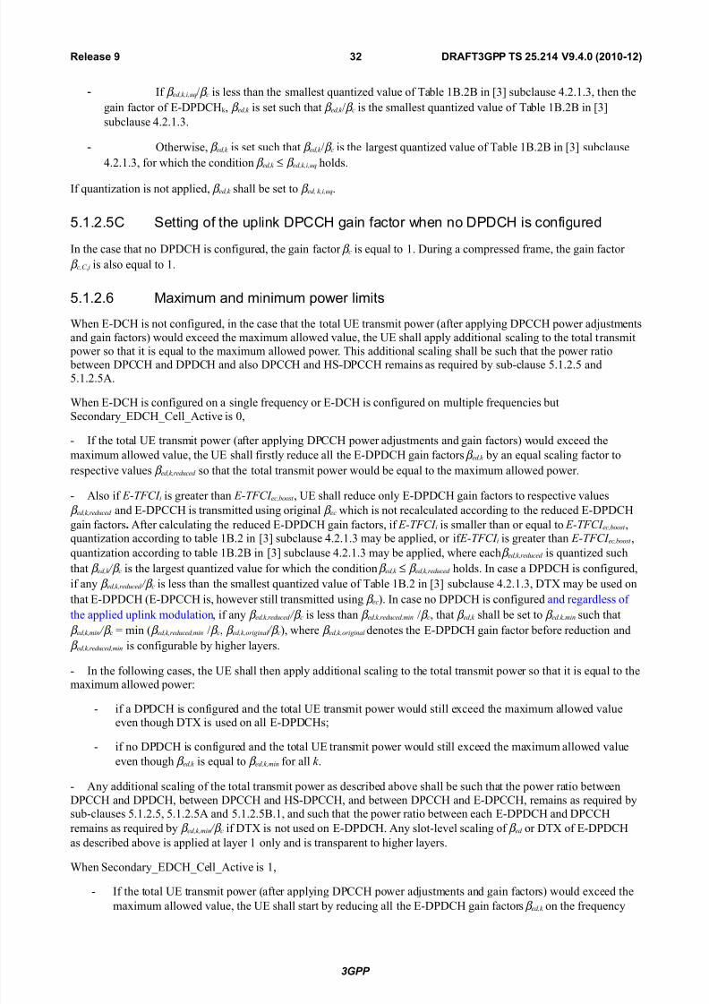
8/18/2019 UTRAN Physical Layer Procedures (FDD)
http://slidepdf.com/reader/full/utran-physical-layer-procedures-fdd 32/99
- %f β ed,k,i,u%<β c is less than the smallest Duantied value of Table ,0.*0 in H3I subclause 9.*.,.3- then the
ain factor of 2:8P81;" - β ed,k is set such that β ed,k <β c is the smallest Duantied value of Table ,0.*0 in H3I
subclause 9.*.,.3.
- Otherwise- β ed,k is set such that β ed,k <β c is the larest Duantied value of Table ,0.*0 in H3I subclause
9.*.,.3- for which the condition β ed,k ≤ β ed,k,i,u% holds.
%f Duantiation is not applied- β ed,k shall be set to β ed, k,i,u%.
5.1.2.5+ Sei' o %e u$li': P++8 ai' a#or %e' 'o P+8 i! #o'iured
%n the case that no 8P81; is confiured- the ain factor β c is eDual to ,. 8urin a compressed frame- the ain factor
β c,C,j is also eDual to ,.
5.1.2.6 Ma/i7u7 a'd 7i'i7u7 $oer li7i!
hen 2:81; is not confiured- in the case that the total 2 transmit power (after applyin 8P11; power adjustments
and ain factors) would e'ceed the ma'imum allowed value- the 2 shall apply additional scalin to the total transmit
power so that it is eDual to the ma'imum allowed power. This additional scalin shall be such that the power ratio between 8P11; and 8P81; and also 8P11; and ;!:8P11; remains as reDuired by sub:clause >.,.*.> and>.,.*.>.
hen 2:81; is confiured on a sinle freDuency or 2:81; is confiured on multiple freDuencies but
!econdary=281;=1ell=ctive is +-
: %f the total 2 transmit power (after applyin 8P11; power adjustments and ain factors) would e'ceed the
ma'imum allowed value- the 2 shall firstly reduce all the 2:8P81; ain factors β ed,k by an eDual scalin factor to
respective values β ed,k,reduced so that the total transmit power would be eDual to the ma'imum allowed power.
: lso if !T"C# i is reater than !T"C# ec,$oost - 2 shall reduce only 2:8P81; ain factors to respective values
β ed,k,reduced and 2:8P11; is transmitted usin oriinal β ec which is not recalculated accordin to the reduced 2:8P81;
ain factors. fter calculatin the reduced 2:8P81; ain factors- if !T"C# i is smaller than or eDual to !T"C# ec,$oost -Duantiation accordin to table ,0.* in H3I subclause 9.*.,.3 may be applied- or if !T"C# i is reater than !T"C# ec,$oost -
Duantiation accordin to table ,0.*0 in H3I subclause 9.*.,.3 may be applied- where each β ed,k,reduced is Duantied such
that β ed,k + β c is the larest Duantied value for which the condition β ed,k ≤ β ed,k,reduced holds. %n case a 8P81; is confiured-
if any β ed,k,reduced + β c is less than the smallest Duantied value of Table ,0.* in H3I subclause 9.*.,.3- 8TL may be used on
that 2:8P81; (2:8P11; is- however still transmitted usin β ec). %n case no 8P81; is confiured and reardless of
the applied uplin" modulation- if any β ed,k,reduced + β c is less than β ed,k,reduced,min <β c- that β ed,k shall be set to β ed,k,min such that
β ed,k,min + β c min (β ed,k,reduced,min <β c- β ed,k,oriinal + β c)- where β ed,k,oriinal denotes the 2:8P81; ain factor before reduction and
β ed,k,reduced,min is confiurable by hiher layers.
: %n the followin cases- the 2 shall then apply additional scalin to the total transmit power so that it is eDual to thema'imum allowed powerF
: if a 8P81; is confiured and the total 2 transmit power would still e'ceed the ma'imum allowed valueeven thouh 8TL is used on all 2:8P81;s
: if no 8P81; is confiured and the total 2 transmit power would still e'ceed the ma'imum allowed value
even thouh β ed,k is eDual to β ed,k,min for all k .
: ny additional scalin of the total transmit power as described above shall be such that the power ratio between
8P11; and 8P81;- between 8P11; and ;!:8P11;- and between 8P11; and 2:8P11;- remains as reDuired bysub:clauses >.,.*.>- >.,.*.> and >.,.*.>0.,- and such that the power ratio between each 2:8P81; and 8P11;
remains as reDuired by β ed,k,min + β c if 8TL is not used on 2:8P81;. ny slot:level scalin of β ed or 8TL of 2:8P81;
as described above is applied at layer , only and is transparent to hiher layers.
hen !econdary=281;=1ell=ctive is ,-
: %f the total 2 transmit power (after applyin 8P11; power adjustments and ain factors) would e'ceed the
ma'imum allowed value- the 2 shall start by reducin all the 2:8P81; ain factors β ed,k on the freDuency
3GPP
RAFT3GPP TS #$%#&' "%'%) (#)&)*&#!3#Release "

8/18/2019 UTRAN Physical Layer Procedures (FDD)
http://slidepdf.com/reader/full/utran-physical-layer-procedures-fdd 33/99
with hihest 8P11; power by an eDual scalin factor to respective values β ed,k,reduced so that the total transmit
power would be eDual to the ma'imum allowed power.
: lso if !T"C# i is reater than !T"C# ec,$oost - 2 shall reduce only 2:8P81; ain factors to respective values
β ed,k,reduced and 2:8P11; is transmitted usin oriinal β ec which is not recalculated accordin to the reduced 2:
8P81; ain factors. fter calculatin the reduced 2:8P81; ain factors- if !T"C# i is smaller than or eDual
to !T"C# ec,$oost - Duantiation accordin to table ,0.* in H3I subclause 9.*.,.3 may be applied- or if !T"C# i isreater than !T"C# ec,$oost - Duantiation accordin to table ,0.*0 in H3I subclause 9.*.,.3 may be applied-
where each β ed,k,reduced is Duantied such that β ed,k + β c is the larest Duantied value for which the condition
β ed,k ≤ β ed,k,reduced holds.
: %f β ed,k,reduced + β c is less than β ed,k,reduced,min <β c then β ed,k shall be set to β ed,k,min such that β ed,k,min + β c min
(β ed,k,reduced,min <β c- β ed,k,oriinal + β c)- where β ed,k,oriinal denotes the 2:8P81; ain factor before reduction and
β ed,k,reduced,min is individually confiured by hiher layers for each freDuency.
: The 2 shall then apply the same procedure on the uplin" freDuency with second hihest 8P11; power.
: %f β ed,k,min + β c min (β ed,k,reduced,min <β c- β ed,k,oriinal + β c) for all activated uplin" freDuencies- any additional scalin of
the total transmit power shall be such that
: the power ratio between 8P11; and ;!:8P11;- and between 8P11; and 2:8P11;- for eachactivated uplin" freDuency remains as reDuired by sub:clauses >.,.*.>- >.,.*.> and >.,.*.>0.,- and such
that the power ratio between each 2:8P81; and 8P11; remains as reDuired by β ed,k,min + β c and
: the power ratio between 8P11; on the activated freDuencies remains unchaned.
ny scalin- and any reduction in the 2:8P81; ain factor as described above- shall only be applied or chaned at a8P11; slot boundary. %n order that the total 2 transmit power does not e'ceed the ma'imum allowed value the
scalin or 2:8P81; ain factor reduction shall be computed usin the ma'imum ;!:8P11; power transmitted in thene't 8P11; slot. %n the case that either an 1$ or a &1$ transmission will start durin the ne't 8P11; slot- thema'imum ;!:8P11; power shall be computed usin one of the followinF
(a) whichever of ∆1$ and ∆ &1$ will be used accordin to whether the transmission will be 1$ or &1$- or
(b) whichever of ∆1$ and ∆ &1$ is the larest.
hen transmittin on a 8P1; the 2 is not reDuired to be capable of reducin its total transmit power below theminimum level reDuired in HAI. ;owever- it may do so- provided that the power ratio between 8P11; and 8P81; andalso between 8P11; and ;!:8P11; remains as specified in sub clause >.,.*.> and >.,.*.>. !ome furtherreulations also apply as followsF %n the case that the total 2 transmit power (after applyin 8P11; power
adjustments and ain factors) would be at or below the total transmit power in the previously transmitted slot and also ator below the reDuired minimum power specified in HAI- the 2 may apply additional scalin to the total transmit power-subject to the followin restrictionsF
: The total transmit power after applyin any additional scalin shall not e'ceed the reDuired minimum power- nor the total transmit power in the previously transmitted slot
: The manitude of any reduction in total transmit power between slots after applyin any additional scalin shallnot e'ceed the manitude of the calculated power reduction before the additional scalin.
%n the case that the total 2 transmit power in the previously transmitted slot is at or below the reDuired minimum
power specfied in HAI and the 8P11; power adjustment and ain factors for the current slot would result in an increasein total power- then no additional scalin shall be used (i.e. power control shall operate as normal).
%f the 2 applies any additional scalin to the total transmit power as described above- this scalin shall be included inthe computation of any 8P11; power adjustments to be applied in the ne't transmitted slot.
3GPP
RAFT3GPP TS #$%#&' "%'%) (#)&)*&#!33Release "

8/18/2019 UTRAN Physical Layer Procedures (FDD)
http://slidepdf.com/reader/full/utran-physical-layer-procedures-fdd 34/99
5.1.3 Void
5.2 o'li': $oer #o'rol
The transmit power of the downlin" channels is determined by the networ". %n eneral the ratio of the transmit power
between different downlin" channels is not specified and may chane with time. ;owever- reulations e'ist asdescribed in the followin subclauses.
;iher layer power settins shall be interpreted as settin of the total power- i.e. the sum of the power from the twoantennas in case of transmit diversity.
5.2.1 P++8P+8-P+8
5.2.1.1 Ge'eral
The downlin" transmit power control procedure controls simultaneously the power of a 8P11; and its correspondin
8P81;s. The power control loop adjusts the power of the 8P11; and 8P81;s with the same amount- i.e. the
relative power difference between the 8P11; and 8P81;s is not chaned. %n case of 7:8P1;- the power control loopadjusts the 7:8P1; power. %f multiple freDuencies are activated in the uplin"- then the downlin" transmit power control procedure shall be followed independently for each associated downlin" freDuency.
7or 8P1;- the relative transmit power offset between 8P11; fields and 8P81;s is determined by the networ". TheT71%- TP1 and pilot fields of the 8P11; are offset relative to the 8P81;s power by PO,- PO* and PO3 d0respectively. The power offsets may vary in time. The method for controllin the power offsets within T/& isspecified in H?I. The power offsets PO,- PO* and PO3 do not apply to 7:8P1;.
5.2.1.2 ;rdi'ary ra'!7i $oer #o'rol
5.2.1.2.1 U e%aiour
The 2 shall enerate TP1 commands to control the networ" transmit power and send them in the TP1 field of theuplin" 8P11;. n e'ample on how to derive the TP1 commands in iven in nne' 0.*.
The 2 shall chec" the downlin" power control mode (8P1=MO82) before eneratin the TP1 commandF
: if 8P1=MO82 + F the 2 sends a uniDue TP1 command in each slot and the TP1 command enerated istransmitted in the first available TP1 field in the uplin" 8P11;. %n case uplin" 8P11; slot format Y9 is usedthen 2 may delay transmittin enerated TP1 command to the ne't available TP1 field
: if 8P1=MO82 , F the 2 repeats the same TP1 command over 3 slots and the new TP1 command istransmitted such that there is a new command at the beinnin of the frame- unless 2=8TL=8/L=2nabled is
T/2- in which case the 2 shall behave as for 8P1=MO82+.
The 8P1=MO82 parameter is a 2 specific parameter controlled by the T/&.
The 2 shall not ma"e any assumptions on how the downlin" power is set by T/&- in order to not prohibit usae of
other T/& power control alorithms than what is defined in subclause >.*.,.*.*.
5.2.1.2.1.1 -P+8 Aualiy are #o'rol
The T/& sets a Duality taret for the 7:8P1;. The 2 autonomously sets a !%/ taret value and adjusts it in orderto achieve the same Duality as the Duality taret set by T/&. The Duality taret is set as a downlin" TP1 commanderror rate taret value for the 7:8P1; belonin to the radio lin" from the ;!:8!1; servin cell as sinalled by theT/&. The 2 shall set the !%/ taret when the 7:8P1; has been setup or reconfiured. %t shall not increase the !%/
taret value before the power control has convered on the current value. The 2 may estimate whether the powercontrol has convered on the current value- by comparin the averaed measured !%/ to the !%/ taret value. hen
5=8TL=ctive is T/2- the 2 shall inore in the !%/ taret value adjustment any TP1 commands received in 7:8P1; slot startin durin an uplin" 8P11; slot which is in an uplin" 8P11; transmission ap.
3GPP
RAFT3GPP TS #$%#&' "%'%) (#)&)*&#!3'Release "

8/18/2019 UTRAN Physical Layer Procedures (FDD)
http://slidepdf.com/reader/full/utran-physical-layer-procedures-fdd 35/99
5.2.1.2.2 UTR&* e%aiour
pon receivin the TP1 commands T/& shall adjust its downlin" 8P11;<8P81; or 7:8P1; power accordinly.
7or 8P1=MO82 +- and for 8P1=MO82, if 2=8TL=8/L=2nabled is T/2-T/& shall estimate thetransmitted TP1 command TP1est to be + or ,- and shall update the power every transmitted slot. %f 8P1=MO82 ,and 2=8TL=8/L=2nabled is 75!2- T/& shall estimate the transmitted TP1 command TP1 est over three slots
to be + or ,- and shall update the power every three slots.
fter estimatin the k Fth TP1 command- T/& shall adjust the current downlin" power P (k :,) Hd0I to a new power P (k ) Hd0I accordin to the followin formulaF
P (k ) P (k : ,) U P TPC (k ) U P $al (k )-
where P TPC (k ) is the k Fth power adjustment due to the inner loop power control- and P $al (k ) Hd0I is a correction
accordin to the downlin" power control procedure for balancin radio lin" powers towards a common reference power.The power balancin procedure and control of the procedure is described in H?I.
P TPC (k ) is calculated accordin to the followin.
%f the value of Limited Po-er #ncrease .sed parameter is #&ot used#- then
=−=+
=+)(TP1if Z
,)(TP1if Z)(P
estTP1
estTP1
TP1k
k k - Hd0I. (,)
%f the value of Limited Po-er #ncrease .sed parameter is #sed#- then the k/th inner loop power adjustment shall be
calculated asF
=≥∆+∆=<∆+∆=
∆−
∆+=
+)(TP1if
e=5imitPower=/ais)( and ,)(TP1if
e=5imitPower=/ais)( and ,)(TP1if
+)(
est
est
est
k
k k
k k
k P TPC sum
TPC sum
TPC
TPC
TPC - Hd0I (*)
where
∑−
−=
=∆,
indow=!ieverain=M85=Power=
)()(k
k i
TPC sum i P k
is the temporary sum of the last 0L_Po-er_Averain_1indo-_2i3e inner loop power adjustments (in d0).
7or the first ( 0L_Po-er_Averain_1indo-_2i3e K ,) adjustments after the activation of the limited power increasemethod- formula (,) shall be used instead of formula (*). Po-er_Raise_Limit and 0L_Po-er_Averain_1indo-_2i3e
are parameters confiured in the T/&.
The power control step sie ∆TP1 can ta"e four valuesF +.>- ,- ,.> or * d0. %t is mandatory for T/& to support ∆TP1 of
, d0- while support of other step sies is optional.
%n addition to the above described formulas on how the downlin" power is updated- the restrictions below apply.
%n case of conestion (commanded power not available)- T/& may disreard the TP1 commands from the 2.
The averae power of transmitted 8P81; symbols over one timeslot shall not e'ceed Ma'imum=85=Power (d0)- norshall it be below Minimum=85=Power (d0). Transmitted 8P81; symbol means here a comple' EP!$ symbol beforespreadin which does not contain 8TL. Ma'imum=85=Power (d0) and Minimum=85=Power (d0) are power limitsfor one channelisation code- relative to the primary 1P%1; power H?I.
%n case of 7:8P1;- the power of the transmitted symbol over one timeslot for a iven 2 shall not e'ceedMa'imum=85=Power (d0)- nor shall it be below Minimum=85=Power (d0). Transmitted symbol means here acomple' EP!$ symbol before spreadin which does not contain 8TL.
%n the case that 5=8TL=ctive is T/2 (see section ?1)- if no uplin" TP1 command is received due to plin"8P11; burst pattern ap as defined in subclause ?1.*.,- P TPC 4k5 derived by the &ode 0 shall be set to ero.
3GPP
RAFT3GPP TS #$%#&' "%'%) (#)&)*&#!3$Release "

8/18/2019 UTRAN Physical Layer Procedures (FDD)
http://slidepdf.com/reader/full/utran-physical-layer-procedures-fdd 36/99
5.2.1.3 Poer #o'rol i' #o7$re!!ed 7ode
The aim of downlin" power control in uplin" or<and downlin" compressed mode is to recover as fast as possible asinal:to:interference ratio (!%/) close to the taret !%/ after each transmission ap.
The 2 behaviour is the same in compressed mode as in normal mode- described in subclause >.*.,.*- e'cept that the
taret !%/ for a 8P1; is offset by hiher layer sinallin. ;owever due to transmission aps in uplin" compressedframes there may be incomplete sets of TP1 commands when 8P1=MO82,.
T/& behaviour is as stated in section >.*.,.*.* e'cept for 8P1=MO82 , where missin TP1 commands in the5 may lead the T/& to chanin its power more freDuently than every 3 slots.
%n compressed mode- compressed frames may occur in either the uplin" or the downlin" or both. %n downlin"compressed frames- the transmission of downlin" 8P81;(s)- 8P11; and 7:8P1; shall be stopped durintransmission aps.
The power of the 8P11; and 8P81; in the first slot after the transmission ap- or the power of the 7:8P1; in the
first slot after the transmission ap- should be set to the same value as in the slot just before the transmission ap.
8urin compressed mode e'cept durin downlin" transmission aps- T/& shall estimate the k Fth TP1 command
and adjust the current downlin" power P (k :,) Hd0I to a new power P (k ) Hd0I accordin to the followin formulaF
P (k ) P (k : ,) U P TPC (k ) U P 2#R4k5 U P $al (k )-
where P TPC (k ) is the k Fth power adjustment due to the inner loop power control- P 2#R4k5 is the ":th power adjustment dueto the downlin" taret !%/ variation- and P $al (k ) Hd0I is a correction accordin to the downlin" power control procedurefor balancin radio lin" powers towards a common reference power. The power balancin procedure and control of the procedure is described in H?I.
8ue to transmission aps in uplin" compressed frames- there may be missin TP1 commands in the uplin".
7or 8P1=MO82 +- and for 8P1=MO82, if 2=8TL=8/L=2nabled is T/2- if no uplin" TP1 command isreceived- P TPC 4k5 derived by the &ode 0 shall be set to ero. Otherwise- P TPC (k ) is calculated the same way as in normal
mode (see sub:clause >.*.,.*.*) but with a step sie ∆!T2P instead of ∆TP1.
7or 8P1=MO82 , if 2=8TL=8/L=2nabled is 75!2- the sets of slots over which the TP1 commands are processed shall remain alined to the frame boundaries in the compressed frame. %f this results in an incomplete set ofTP1 commands- the 2 shall transmit the same TP1 commands in all slots of the incomplete set.
The power control step sie ∆!T2P ∆/P:TP1 durin /P5 slots after each transmission ap and ∆!T2P ∆TP1 otherwise-
whereF
: /P5 is the recovery period lenth and is e'pressed as a number of slots. /P5 is eDual to the minimum value outof the transmission ap lenth and A slots. %f a transmission ap or an plin" 8P11; burst pattern ap asdefined in subclause ?1.* is scheduled to start before /P5 slots have elapsed- then the recovery period shall end
at the start of the ap- and the value of /P5 shall be reduced accordinly.
: ∆/P:TP1 is called the recovery power control step sie and is e'pressed in d0. ∆/P:TP1 is eDual to the minimumvalue of 3 d0 and *∆TP1.
7or 7:8P1;- P 2#R(k ) 0.
7or 8P1;- the power offset P 2#R(k ) δPcurr : δP prev- where δPcurr and δP prev are respectively the value of δP in the current
slot and the most recently transmitted slot and δP is computed as followsF
δP ma' (∆P,=compression- R- ∆Pn=compression) U ∆P,=codin U ∆P*=codin
where n is the number of different TT% lenths amonst TT%s of all Tr1hs of the 11Tr1h- where ∆P,=codin and
∆P*=codin are computed from uplin" parameters 8elta!%/,- 8elta!%/*- 8elta!%/after,- 8elta!%/after* sinaled by
hiher layers asF
: ∆P,=codin 8elta!%/, if the start of the first transmission ap in the transmission ap pattern is within the
current frame and 2=8TL=8/L=2nabled is 75!2.
3GPP
RAFT3GPP TS #$%#&' "%'%) (#)&)*&#!3+Release "

8/18/2019 UTRAN Physical Layer Procedures (FDD)
http://slidepdf.com/reader/full/utran-physical-layer-procedures-fdd 37/99
: ∆P,=codin 8elta!%/after, if the current frame just follows a frame containin the start of the first
transmission ap in the transmission ap pattern and 2=8TL=8/L=2nabled is 75!2.
: ∆P*=codin 8elta!%/* if the start of the second transmission ap in the transmission ap pattern is within the
current frame and 2=8TL=8/L=2nabled is 75!2.
: ∆P*=codin 8elta!%/after* if the current frame just follows a frame containin the start of the secondtransmission ap in the transmission ap pattern and 2=8TL=8/L=2nabled is 75!2.
: ∆P,=codin + d0 and ∆P*=codin + d0 in all other cases.
and ∆Pi=compression is defined by F
: ∆Pi=compression 3 d0 for downlin" frames compressed by reducin the spreadin factor by *.
: ∆Pi=compression + d0 in all other cases.
%n case several compressed mode patterns are used simultaneously- a δP offset is computed for each compressed mode
pattern and the sum of all δP offsets is applied to the frame.
7or all time slots e'cept those in transmissions aps- the averae power of transmitted 8P81; symbols over one
timeslot shall not e'ceed Ma'imum=85=Power (d0) by more than δPcurr - nor shall it be below Minimum=85=Power
(d0). Transmitted 8P81; symbol means here a comple' EP!$ symbol before spreadin which does not contain 8TL.Ma'imum=85=Power (d0) and Minimum=85=Power (d0) are power limits for one channelisation code- relative to the primary 1P%1; power H?I.
7or 7:8P1;- for all time slots e'cept those in transmissions aps the power of the transmitted symbol over one timeslotfor a iven 2 shall not e'ceed Ma'imum=85=Power (d0)- nor shall it be below Minimum=85=Power (d0).
Transmitted symbol means here a comple' EP!$ symbol before spreadin which does not contain 8TL.
5.2.1.4 Void
5.2.2 Void
5.2.3 Void
5.2.4 &<+8
The 2 is informed about the relative transmit power of the %s (measured as the power per transmitted acDuisitionindicator) and the relative transmit power of the 2%s (measured as the power per transmitted e'tended acDuisitionindicator)- both compared to the primary 1P%1; transmit power by the hiher layers.
5.2.5 P<+8
The 2 is informed about the relative transmit power of the P%1; (measured as the power over the pain indicators)
compared to the primary 1P%1; transmit power by the hiher layers.
5.2.6 S-++P+8
The T71% and pilot fields may be offset relative to the power of the data field. The power offsets may vary in time.
7or M0!7& 71; transmission with ,?EM- the 2 is informed about the relative transmit power of the !:11P1;(measured as the power of the transmitted data of !:11P1;) compared to the primary 1P%1; transmit power by thehiher layers.
3GPP
RAFT3GPP TS #$%#&' "%'%) (#)&)*&#!3,Release "

8/18/2019 UTRAN Physical Layer Procedures (FDD)
http://slidepdf.com/reader/full/utran-physical-layer-procedures-fdd 38/99
5.2. Void
5.2.B Void
5.2.9 Void
5.2.10 8S-S++8
The ;!:!11; power control is under the control of the node 0. %t may e.. follow the power control commands sent by
the 2 to the node 0 or any other power control procedure applied by the node 0.
5.2.11 8S-PS+8
The ;!:P8!1; power control is under the control of the node 0. hen the ;!:P8!1; is transmitted usin ,?EMor ?9EM- the 2 may assume that the power is "ept constant durin the correspondin ;!:8!1; subframe.
%n case of multiple ;!:P8!1; transmission to one 2- all the ;!:P8!1;s intended for that 2 shall be transmittedwith eDual power.
The sum of the powers used by all ;!:P8!1;s- ;!:!11;s- 2:G1;s- 2:/G1;s and 2:;%1;s in a cell shall note'ceed the value of 62!P02C6, 62!2CC6, !A7C6, !R7C6 and !6#C6 Total Po-er if sinaled by hiher layersH?I.
5.2.12 -&G+8
The 2:G1; power control is under the control of the node 0. %t may e.. follow the power control commands sent bythe 2 to the node 0 or any other power control procedure applied by the node 0.
5.2.13 -8<+8
The 2:;%1; power control is under the control of the node 0. %t may e.. follow the power control commands sent bythe 2 to the node 0 or any other power control procedure applied by the node 0.
5.2.14 -RG+8
The 2:/G1; power control is under the control of the node 0. %t may e.. follow the power control commands sent bythe 2 to the node 0 or any other power control procedure applied by the node 0.
5.2.15 M<+8
The 2 is informed about the relative transmit power of the M%1; (measured as the power over the notification
indicators) compared to the primary 1P%1; transmit power by the hiher layers.
5.2.16 S-+P<+8
%n case the 2 is confiured in M%MO mode- and !:1P%1; is used as a phase reference for a second transmit antenna-
the 2 is informed about the relative transmit power of the !:1P%1; compared to the primary 1P%1; transmit power by the hiher layers.
3GPP
RAFT3GPP TS #$%#&' "%'%) (#)&)*&#!3-Release "

8/18/2019 UTRAN Physical Layer Procedures (FDD)
http://slidepdf.com/reader/full/utran-physical-layer-procedures-fdd 39/99
6 Ra'do7 a##e!! $ro#edure
6.1 P%y!i#al ra'do7 a##e!! $ro#edure
The physical random access procedure described in this subclause is initiated upon reDuest from the M1 sublayer (cf.HCI).
0efore the physical random:access procedure can be initiated- 5ayer , shall receive the followin information from thehiher layers (//1)F
: The preamble scramblin code.
: The messae lenth in time- either ,+ or *+ ms.
: The %1;=Transmission=Timin parameter H+ or ,I.
: The set of available sinatures and the set of available /1; sub:channels for each ccess !ervice 1lass
(!1). !ub:channels are defined in subclause ?.,.,.
: The power:rampin factor Power /amp !tep Hinteer +I.
: The parameter Preamble /etrans Ma' Hinteer +I.
: The initial preamble power Preamble=%nitial=Power.
: The Power offset P p:m Pmessae:control K P preamble- measured in d0- between the power of the last transmitted preamble and the control part of the random:access messae.
: The set of Transport 7ormat parameters. This includes the power offset between the data part and the control partof the random:access messae for each Transport 7ormat.
&ote that the above parameters may be updated from hiher layers before each physical random access procedure is
initiated.
t each initiation of the physical random access procedure- 5ayer , shall receive the followin information from thehiher layers (M1)F
: The Transport 7ormat to be used for the P/1; messae part.
: The !1 of the P/1; transmission.
: The data to be transmitted (Transport 0loc" !et).
The physical random:access procedure shall be performed as followsF
, 8erive the available uplin" access slots- in the ne't full access slot set- for the set of available /1; sub:channels within the iven !1 with the help of subclauses ?.,.,. and ?.,.*. /andomly select one access slotamon the ones previously determined. %f there is no access slot available in the selected set- randomly select oneuplin" access slot correspondin to the set of available /1; sub:channels within the iven !1 from the ne't
access slot set. The random function shall be such that each of the allowed selections is chosen with eDual probability.
* /andomly select a sinature from the set of available sinatures within the iven !1. The random functionshall be such that each of the allowed selections is chosen with eDual probability.
3 !et the Preamble /etransmission 1ounter to Preamble /etrans Ma'.
9 %f the Preamble=%nitial=Power is below the minimum level reDuired in HAI- set the 1ommanded Preamble Powerto a value- which shall be at or above the Preamble=%nitial=Power and at or below the reDuired minimum powerspecified in HAI. Otherwise set the parameter 1ommanded Preamble Power to Preamble=%nitial=Power.
> %n the case that the 1ommanded Preamble Power e'ceeds the ma'imum allowed value- set the preambletransmission power to the ma'imum allowed power. %n the case that the 1ommanded Preamble Power is belowthe minimum level reDuired in HAI- set the preamble transmission power to a value- which shall be at or above the
3GPP
RAFT3GPP TS #$%#&' "%'%) (#)&)*&#!3"Release "

8/18/2019 UTRAN Physical Layer Procedures (FDD)
http://slidepdf.com/reader/full/utran-physical-layer-procedures-fdd 40/99
1ommanded Preamble Power and at or below the reDuired minimum power specified in HAI. Otherwise set the preamble transmission power to the 1ommanded Preamble Power. Transmit a preamble usin the selected uplin" access slot- sinature- and preamble transmission power.
? %f no positive or neative acDuisition indicator (% ≠ U, nor K,) correspondin to the selected sinature is
detected in the downlin" access slot correspondin to the selected uplin" access slotF
?., !elect the ne't available access slot in the set of available /1; sub:channels within the iven !1.
?.* /andomly select a new sinature from the set of available sinatures within the iven !1. The randomfunction shall be such that each of the allowed selections is chosen with eDual probability.
?.3 %ncrease the 1ommanded Preamble Power by ∆P+ Power /amp !tep Hd0I. %f the 1ommanded Preamble
Power e'ceeds the ma'imum allowed power by ?d0- the 2 may pass 5, status (J&o ac" on %1;J) to thehiher layers (M1) and e'it the physical random access procedure.
?.9 8ecrease the Preamble /etransmission 1ounter by one.
?.> %f the Preamble /etransmission 1ounter + then repeat from step >. Otherwise pass 5, status (J&o ac" on%1;J) to the hiher layers (M1) and e'it the physical random access procedure.
A %f a neative acDuisition indicator correspondin to the selected sinature is detected in the downlin" access slot
correspondin to the selected uplin" access slot- pass 5, status (J&ac" on %1; receivedJ) to the hiher layers(M1) and e'it the physical random access procedure.
B Transmit the random access messae three or four uplin" access slots after the uplin" access slot of the lasttransmitted preamble dependin on the %1; transmission timin parameter. Transmission power of the control
part of the random access messae should be P p:m Hd0I hiher than the power of the last transmitted preamble.
Transmission power of the data part of the random access messae is set accordin to subclause >.,.,.*.
C Pass 5, status J/1; messae transmittedJ to the hiher layers and e'it the physical random access procedure.
6.1.1 R&+8 !u-#%a''el!
/1; sub:channel defines a sub:set of the total set of uplin" access slots. There are a total of ,* /1; sub:channels. /1; sub:channel Yi (i +- R- ,,) consists of the followin uplin" access slotsF
: plin" access slot Yi leadin by τ p:a chips the downlin" access slot Yi contained within the ,+ ms interval that is
time alined with P:11P1; frames for which !7& mod B + or !7& mod B ,.
: 2very ,*th access slot relative to this access slot.
The access slots of different /1; sub:channels are also illustrated in Table A.
Ta1le ,/ The a4aila1le uplink access slots for different RA56 su1*channels
S* 7odulo B o
#orre!$o'di' P-++P+8 ra7e
Su1*channel nu1er
0 1 2 3 4 5 6 B 9 10 11
0 0 1 2 3 4 5 6
1 12 13 14 B 9 10 11
2 0 1 2 3 4 5 6
3 9 10 11 12 13 14 B
4 6 0 1 2 3 4 5
5 B 9 10 11 12 13 14
6 3 4 5 6 0 1 2
B 9 10 11 12 13 14
3GPP
RAFT3GPP TS #$%#&' "%'%) (#)&)*&#!')Release "

8/18/2019 UTRAN Physical Layer Procedures (FDD)
http://slidepdf.com/reader/full/utran-physical-layer-procedures-fdd 41/99
6.1.2 R&+8 a##e!! !lo !e!
The P/1; contains two sets of access slots as shown in 7iure *. ccess slot set , contains P/1; slots + K A and
starts τ p:a chips before the downlin" P:11P1; frame for which !7& mod * +. ccess slot set * contains P/1; slots
B : ,9 and starts (τ p:a K*>?+) chips before the downlin" P:11P1; frame for which !7& mod * ,.
&<+8 a##e!!!lo!
10 7!
C0 C1 C2 C3 C14C13C12C11C10C9CBCC6C5C4τ$-a
C0 C1 C2 C3 C14C13C12C11C10C9CBCC6C5C4
PR&+8a##e!! !lo!
S)* 7od 2 ? 0 S)* 7od 2 ? 1
10 7!
&##e!! !lo !e 1 &##e!! !lo !e 2
Fi.ure #/ PRA56 access slot and downlink A256 relation ( p*a 7 ,+-) chips!
6.1& P%y!i#al ra'do7 a##e!! $ro#edure or '%a'#ed U$li': i'+""=&+8 !ae a'd <" 7ode
The physical random access procedure described in this subclause is initiated upon reDuest from the M1 sublayer (cf.HCI).
0efore the physical random:access procedure can be initiated- 5ayer , shall receive the followin information from the
hiher layers (//1)F
: The preamble scramblin code.
: The %1;=Transmission=Timin parameter H+ or ,I.
: The set of available sinatures and the set of available /1; sub:channels correspondin to 2:81; resourcesfor each ccess !ervice 1lass (!1). !ub:channels are defined in subclause ?.,.,.
: The total number of 2:81; resources confiured in the cell.
: The power:rampin factor Power /amp !tep Hinteer +I.
: The parameter Preamble /etrans Ma' Hinteer +I.
: The initial preamble power Preamble=%nitial=Power.
: The Power offset P p:e Pdpcch K P preamble- measured in d0- between the power of the last transmitted preamble andthe initial 8P11; transmission power.
: The number of TT%s in which only the uplin" 8P11; is sent before the 2:81; transmission may start
&ote that the above parameters may be updated from hiher layers before each physical random access procedure isinitiated.
t each initiation of the physical random access procedure- 5ayer , shall receive the followin information from thehiher layers (M1)F
: The !1 of the P/1; transmission.
The physical random:access procedure shall be performed as followsF
3GPP
RAFT3GPP TS #$%#&' "%'%) (#)&)*&#!'&Release "

8/18/2019 UTRAN Physical Layer Procedures (FDD)
http://slidepdf.com/reader/full/utran-physical-layer-procedures-fdd 42/99
, 8erive the available uplin" access slots- in the ne't full access slot set- for the set of available /1; sub:channels within the iven !1 with the help of subclauses ?.,.,. and ?.,.*. /andomly select one access slotamon the ones previously determined. %f there is no access slot available in the selected set- randomly select oneuplin" access slot correspondin to the set of available /1; sub:channels within the iven !1 from the ne't
access slot set. The random function shall be such that each of the allowed selections is chosen with eDual probability.
* /andomly select a sinature from the set of available sinatures within the iven !1. The random functionshall be such that each of the allowed selections is chosen with eDual probability.
3 !et the Preamble /etransmission 1ounter to Preamble /etrans Ma'.
9 %f the Preamble=%nitial=Power is below the minimum level reDuired in HAI- set the 1ommanded Preamble Powerto a value- which shall be at or above the Preamble=%nitial=Power and at or below the reDuired minimum powerspecified in HAI. Otherwise set the parameter 1ommanded Preamble Power to Preamble=%nitial=Power.
> %n the case that the 1ommanded Preamble Power e'ceeds the ma'imum allowed value- set the preambletransmission power to the ma'imum allowed power. %n the case that the 1ommanded Preamble Power is belowthe minimum level reDuired in HAI- set the preamble transmission power to a value- which shall be at or above the1ommanded Preamble Power and at or below the reDuired minimum power specified in HAI. Otherwise set the
preamble transmission power to the 1ommanded Preamble Power. Transmit a preamble usin the selected uplin" access slot- sinature- and preamble transmission power.
? %f no positive or neative acDuisition indicator (% ≠ U, nor K,) correspondin to the selected sinature is
detected in the downlin" access slot correspondin to the selected uplin" access slotF
?., !elect the ne't available access slot in the set of available /1; sub:channels within the iven !1.
?.* /andomly select a new sinature from the set of available sinatures within the iven !1. The randomfunction shall be such that each of the allowed selections is chosen with eDual probability.
?.3 %ncrease the 1ommanded Preamble Power by ∆P+ Power /amp !tep Hd0I. %f the 1ommanded Preamble
Power e'ceeds the ma'imum allowed power by ?d0- the 2 may pass 5, status (J&o ac" on %1;J) to thehiher layers (M1) and e'it the physical random access procedure.
?.9 8ecrease the Preamble /etransmission 1ounter by one.
?.> %f the Preamble /etransmission 1ounter + then repeat from step >. Otherwise pass 5, status (J&o ac" on%1;J) to the hiher layers (M1) and e'it the physical random access procedure.
A %f a neative acDuisition indicator on %1; correspondin to the selected sinature is detected in the downlin"access slot correspondin to the selected uplin" access slot.
A., %f no 2'tended cDuisition %ndicator sinature set is confiured in the cell- pass 5, status (S&ac" on %1;received) to the hiher layers (M1) and e'it the physical random access procedure.
A.* %f an 2'tended cDuisition %ndicator sinature set is confiured in the cell- detect which one of the defined2'tended cDuisition %ndicator sinatures is present.
A.*., %f the detected 2'tended cDuisition %ndicator sinature and modulation symbol corresponds to
[&1$\ as defined in H,I- pass 5, status (S&ac" on %1; received) to the hiher layers (M1) and e'itthe physical random access procedure.
A.*.* %f the detected 2'tended cDuisition %ndicator sinature and modulation symbol do not correspond to[&1$\- pass 5, status (Sc" on %1; received) with the correspondin 2:81; resource inde' asdefined in H,I to hiher layers (M1) and s"ip step B.
B %f a positive acDuisition indicator on %1; correspondin to the selected sinature is detected in the downlin"access slot correspondin to the selected uplin" access slot- pass 5, status (Sc" on %1; received) with thedefault 2:81; resource inde' correspondin to the selected sinature as defined in H,I to hiher layers (M1)-
C !tart transmittin 8P11; (timin as specified in H,I and synchronisation accordin to synchronisation procedure ). The initial transmission power of 8P11; prior to startin the 2:81; transmission should be
P p:e Hd0I hiher than the power of the last transmitted preamble.
3GPP
RAFT3GPP TS #$%#&' "%'%) (#)&)*&#!'#Release "

8/18/2019 UTRAN Physical Layer Procedures (FDD)
http://slidepdf.com/reader/full/utran-physical-layer-procedures-fdd 43/99
,+ Proceed to transmittin 2:8P11; and 2:8P81; as instructed by M1 layer after the defined number of TT%sof 8P11; only transmission has passed.
6.2 Void
6& 8S-S+8-relaed $ro#edure!
6&.1 Ge'eral $ro#edure
!chedulin and transport format selection is controlled by the M1:hs or M1:ehs sublayer in the &ode 0 HCI.
The followin parameters are sinalled to the physical layer in the 2 and the &ode 0 from hiher layersF
,) ;!:!11; set to be monitored in the servin ;!:8!1; cell
*) /epetition factor of 1$<&1$F &=ac"nac"=transmit
3) 1hannel Euality %ndicator (1E%) feedbac" cycle k
9) /epetition factor of 1E%F &=cDi=transmit
>) Measurement power offset Γ
?) !tatus of preamble<postamble transmissionF ;/E=preamble=mode
A) !tatus of ?9EM confiuration
B) !et of P:1P%1; and<or !:1P%1; (which shall be transmitted on the same scramblin code) that shall be usedfor ;!:P8!1; demodulation in case the 2 is confiured in M%MO mode
C) The number N of dynamic sinle<dual 1E% reports out of a seDuence of M 1E% reports in case the 2 isconfiured in M%MO mode (not applicable when sinle:stream restriction is confiured)F N =cDi=type- M =cDi-respectively
,+) !et of transport bloc" sies confiured for ;!:!11;:less operation
,,) !et of ;!:P8!1;s confiured for ;!:!11;:less operation
,*) !tatus variables ;!=!11;=52!!=!TT! and 8TL=8/L=!TT!
,3) 2nablin=8elay
,9) //1 protocol state (1255=81;- 1255=71;- 1255=P1; or /=P1;)
,>) ;:/&T% values (dedicated ;:/&T%- common ;:/&T%- 011; specific ;:/&T%) to be monitored when the 2is confiured to receive ;!:8!1; in 1255=71; or 1255=P1; state
,?) ;!:8!1; pain system information- which includes the followin information when the 2 is confiured toreceive ;!:8!1; in /=P1; state or in 1255=P1; stateF
a. &umber of P11; transmissionsF The number of subframes used to transmit PG%&G TNP2 , as
defined in H>I.
b. ;!:P8!1; 1hannelisation 1ode confiured for ;!:!11; less pain operation
c. Transport 0loc" !ieF 5ist of Transport 0loc" !ies
,A) !tatus of M%MO confiuration
,B) ;!:!11; set to be monitored in a secondary servin ;!:8!1; cell
,C) ;!:!11; set to be monitored in one non:servin cell
3GPP
RAFT3GPP TS #$%#&' "%'%) (#)&)*&#!'3Release "

8/18/2019 UTRAN Physical Layer Procedures (FDD)
http://slidepdf.com/reader/full/utran-physical-layer-procedures-fdd 44/99
*+) !tatus of [!upport for different ;!:!11;s in contiuous TT%s\
%f ;!=!11;=52!!=!TT! is T/2 then ;!:!11;=less=mode,. Otherwise ;!:!11;=less=mode+.
;!:!11;:less=ctive shall be set to T/2 while ;!:!11;=less=mode, and ;!:!11;:less operation is activated.Otherwise ;!:!11;=less=ctive shall be set to 75!2. ;!:!11;:less operation shall be activated at the time when;!:!11;=less=mode is set to ,- and may be further deactivated or activated by ;!:!11; orders as specified in H*I.This ordered deactivation or activation of the ;!:!11;:less operation is applied by the 2 ,* slots after the end of the;!:!11; subframe deliverin the order.
%f the hiher layers set 8TL=8/L=!TT! to T/2 (as described in H>I) then 2=8TL=8/L=2nabled is 75!2until 2nablin=8elay radio frames have passed. fter the hiher layers have set 8TL=8/L=!TT! to T/2 (asdescribed in H>I) and 2nablin=8elay radio frames have passed then 2=8TL=8/L=2nabled is T/2. Otherwise2=8TL=8/L=2nabled is 75!2.
%f the 2 is confiured with a secondary servin ;!:8!1; cell- then !econdary=1ell=2nabled is ,- otherwise!econdary=1ell=2nabled is + and !econdary=1ell=ctive is +. The secondary servin ;!:8!1; cell shall be activatedat the time when !econdary=1ell=2nabled is set to ,- and may further be deactivated or activated by ;!:!11; ordersas specified in H*I. !econdary=1ell=ctive shall be set to , while !econdary=1ell=2nabled is , and the secondaryservin ;!:8!1; cell is activated- otherwise !econdary=1ell=ctive shall be set to +. %f !econdary=1ell=ctive is
already eDual to , when the 2 receives an ;!:!11; order for activation of the secondary servin ;!:8!1; cell asspecified in H*I- then the 2 shall not chane the status of !econdary=1ell=ctive reardin the contents of the order- but shall transmit the ;/E:1$ ac"nowledin the ;!:!11; order.
%f the 2 is not confiured with multiple uplin" freDuencies- ;!:!11; ordered deactivation or activation of thesecondary servin ;!:8!1; cell is applied by the 2 ,* slots after the end of the ;!:!11; subframe deliverin the
order- and any transient behaviour related to this chane should ta"e place before this point in time. The correspondinchane of the ;!:8P11; channel codin scheme as specified in H*I is applied by the 2 at the first ;!:8P11;subframe boundary after the activation or deactivation has been applied. %f the secondary servin ;!:8!1; cell isconfiured in a band that does not contain the servin ;!:8!1; cell- the ma'imum allowed interruption time for the primary uplin" freDuency and servin ;!:8!1; cell is , slot and the interrupt shall ta"e place durin the ne't 85 ;!:!11; slot after the end of the ;!:8P11; slot that contains the ;/E:1$ information ac"nowledin the ;!:
!11; order.
%f the 2 is confiured with multiple uplin" freDuencies- ;!:!11; ordered deactivation or activation of the secondaryservin ;!:8!1; cell is applied by the 2 ,B slots after the end of the ;!:!11; subframe deliverin the order- andany transient behaviour related to this chane should ta"e place before this point in time. The correspondin chane ofthe ;!:8P11; channel codin scheme as specified in H*I is applied by the 2 at the first ;!:8P11; subframe
boundary after the activation or deactivation has been applied.
6&.1.1 U $ro#edure or re#eii' 8S-S+8 a'd 8S-S++8 i' %e+""=+8 !ae
&OT2F The &ode 0 procedure for transmittin the ;!:8!1; and the ;!:!11; is specified in subclause ?.,.3.
%n this sub:clause- sub:frame n on the ;!:!11;s refers to the sub:frame which is associated with sub:frame n on the;!:P8!1; as defined in H,I- and sub:frame n on the ;!:8P11; refers to the sub:frame which is related to sub:frame
n on the ;!:P8!1; as defined in H,I.
%f the 2 did not detect consistent control information intended for this 2 on any of the ;!:!11;s in the ;!:!11;set in the immediately precedin subframe n K ,- the 2 shall in sub:frame n monitor all ;!:!11;s in the ;!:!11;set. The ma'imum sie of the ;!:!11; set in the servin ;!:8!1; cell is 9.
%f ?9EM is not confiured for the 2 and [!upport for different ;!:!11;s in contiuous TT%s\ is false- then if the2 did detect consistent control information intended for this 2 in the immediately precedin subframe n K ,- it issufficient in sub:frame n to only monitor the same ;!:!11; used in the immediately precedin subframe n K ,. %f?9EM is confiured for the 2 or [!upport for different ;!:!11;s in contiuous TT%s\ is true- then if the 2 diddetect consistent control information intended for this 2 in the immediately precedin subframe n K ,- the 2 shall insub:frame n monitor all ;!:!11;s in the ;!:!11; set. These rules apply reardless of the value of ;!:
!11;=less=mode.
%f !econdary=1ell=ctive is ,-
3GPP
RAFT3GPP TS #$%#&' "%'%) (#)&)*&#!''Release "

8/18/2019 UTRAN Physical Layer Procedures (FDD)
http://slidepdf.com/reader/full/utran-physical-layer-procedures-fdd 45/99
: The 2 shall simultaneously monitor an ;!:!11; set in the secondary servin ;!:8!1; cell- and receive ;!:8!1; if it is scheduled in that cell. The ma'imum sie of the ;!:!11; set in a secondary servin ;!:8!1;cell is 9 and the ma'imum number of ;!:!11;s monitored by the 2 across both the servin ;!:8!1; celland the secondary servin ;!:8!1; cell is ?.
: 7rom the servin ;!:8!1; cell- the 2 shall be able to receive up to one ;!:8!1; if M%MO mode is not
confiured or two ;!:8!1;s if M%MO mode is confiured or one ;!:!11; order.: %n addition- from the secondary servin ;!:8!1; cell- the 2 shall be able to simultaneously receive up to one
;!:8!1; if M%MO mode is not confiured or two ;!:8!1;s if M%MO mode is confiured or one ;!:!11;order.
: ;!:!11;:less ;!:8!1; transmission shall not be used in a secondary servin ;!:8!1; cell.
: The 2 behaviour is unspecified in case contradictory ;!:!11; orders (i.e. orders for activation anddeactivation of the same functionality) are received from the servin ;!:8!1; cell and the secondary servin;!:8!1; cell durin the same subframe.
The 2 can be confiured to simultaneously monitor a ma'imum of , ;!:!11; in one non:servin cell. This ;!:!11; is only used for ;!:!11; orders that indicate ;!:8!1; servin cell chane as defined in section 9.?1.*.*., in
H*I. pon successfully receivin an ;!:!11; order that indicates ;!:8!1; servin cell chane from this non:servincell- the 2 shall be able to start listenin to the full confiured ;!:!11; set from this new servin cell and from thenew secondary servin ;!:8!1; cell if confiured by hiher layers- at the activation time confiured by hiher layersif the activation time is not eDual to Snow- or otherwise within 9+ ms from the end of the subframe in which the ;!:!11; order is received.
hen the 2 monitors ;!:!11;s- the 2 shall only consider the control information to be consistent if eitherF
: the decoded #channeliation:code:set information# is lower than or eDual to #ma'imum number of ;!:8!1;codes received# in its 2 capability and the decoded #modulation scheme information# is valid in terms of its 2capability-
or
: the decoded #channeliation:code:set information# and decoded [modulation scheme information\ correspond toan indication of an ;!:!11; order as defined in H*I.
1ontrol information for one 2 shall not be transmitted from the servin cell on more than one ;!:!11; in a sinlesub:frame.
%f a 2 detects that one of the monitored ;!:!11;s in sub:frame n carries consistent control information intended forthis 2- the 2 shall perform the followinF
: %f the decoded #channeliation:code:set information# and decoded [modulation scheme information\ do notcorrespond to an indication of an ;!:!11; order- start receivin the ;!:P8!1;s indicated by this consistentcontrol information
: %f the 1/1 of the ;!:!11; is O$F
- %f ;!:!11;=less=mode, and the T7/% value corresponds to the retransmissions of ;!:!11;:lessoperation- the transport bloc" sie information shall be derived from the sinalled transport bloc" sieindicator as defined in H>I and HCI.
- 2lse if 2=8TL=8/L=2nabled is T/2 or ;!:!11;=less=mode, or !econdary=1ell=2nabled is not +-
and the [channeliation:code:set information\ and [modulation scheme information\ correspond to an ;!:!11; order- the 2 shallF
o if the T7/% value corresponds to an ;!:!11; order
%f the ;!:!11; order was sent by the servin ;!:8!1; cell or the secondary servin
;!:8!1; cell- transmit 1$ information in the slot allocated to the ;/E:1$ in the
correspondin ;!:8P11; sub:frame as defined in H,I
Process the ;!:!11; orders as described in subclauses ?.,- ?0 and ?1.9.
3GPP
RAFT3GPP TS #$%#&' "%'%) (#)&)*&#!'$Release "

8/18/2019 UTRAN Physical Layer Procedures (FDD)
http://slidepdf.com/reader/full/utran-physical-layer-procedures-fdd 46/99
o else- discard the information received on this ;!:!11;.
- 2lse- the transport bloc" sie information shall be derived from the sinalled T7/% value as defined in HCI.
o %f the #;ybrid:/E process information# is not included in the set confiured by upper layers- the
2 shall discard the information received on this ;!:!11; and on the ;!:P8!1;s.
: 2lse- if ;!:!11;=less=ctive is T/2- the 2 may start receivin the ;!:P8!1;s confiured for ;!:!11;:less operation and attempt to decode the ;!:8!1; bits based on the set of possible ;!:8!1; transport bloc" sies
confiured for ;!:!11;:less operation. Otherwise- the 2 shall discard the information received on this ;!:!11;and ;!:P8!1;.
Otherwise, if the 2 does not detect consistent control information intended for this 2 on any of the ;!:!11;s in its;!:!11; sets- the 2 shall perform the followinF
: the 2 shall discard the information received on this ;!:!11;.
: if ;!:!11;=less=ctive is T/2- the 2 shall start receivin the ;!:P8!1;s confiured for ;!:!11;:lessoperation and attempt to decode the ;!:8!1; bits based on the set of possible ;!:8!1; transport bloc" siesconfiured for ;!:!11;:less operation.
: otherwise- the 2 shall discard the information received on the ;!:P8!1;s.
%f 5=8TL=ctive is T/2 (see section ?1) and either of the followin is trueF
: the 2 detects consistent control information intended for this 2 and the T7/% value does not correspond to an;!:!11; order- or
: the 2 has successfully decoded ;!:P8!1;s intended for this 2
then- at the ;!:8P11; sub frame that contains or would contain the ;/E:1$ correspondin to the ;!:!11; or
to the ;!:P8!1;s that enerated the priority chane- the 2 shall perform the followinF
: set 1E%=8TL=Priority to , and-
: reset the 1E% nominal reportin timer to 1E%=8TL=T%M2/.
%f ;/E=preamble=mode , and the information received on ;!:!11; is not discarded- the 2 shallF
- transmit a ;/E Preamble (P/2) in the slot allocated to ;/E:1$ in ;!:8P11; sub:frame n K ,- unlessan 1$ or &1$ or any combination of 1$ and &1$ is to be transmitted in sub:frame n K , as a result ofan ;!:8!1; transmission earlier than sub:frame n on the ;!:P8!1;- and
- if &=ac"nac"=transmit ,- the 2 shall transmit a ;/E Preamble in the slot allocated to ;/E:1$ in ;!:8P11; sub:frame n K *- unless an 1$ or &1$ or any combination of 1$ and &1$ is to be transmittedin sub:frame n K * as a result of an ;!:8!1; transmission earlier than sub:frame n on the ;!:P8!1;.
The 2 shall transmit the 1$<&1$ information received from M1:hs or M1:ehs in the slot allocated to the
;/E:1$ in the correspondin ;!:8P11; sub:frame as defined in H,I. hen N_ acknack_transmit is reaterthan one- the 2 shallF
: repeat the transmission of the 1$<&1$ information over the ne't ( N_ acknack_transmit!*) consecutive;!:8P11; sub:frames- in the slots allocated to the ;/E:1$ as defined in H,I and
: not attempt to receive any ;!:!11; in ;!:!11; subframes correspondin to ;!:8P11; sub:frames inwhich the 1$<&1$ information transmission is repeated- nor to receive or decode transport bloc"s fromthe ;!:P8!1; in ;!:8!1; sub:frames correspondin to ;!:8P11; sub:frames in which the1$<&1$ information transmission is repeated.
%f 1$ or &1$ or any combination of 1$ and &1$ is transmitted in ;!:8P11; sub:frame n- and;/E=preamble=mode , and 2 %nterTT% ] N_acknack_transmit - then the 2 shallF
- transmit a ;/E Postamble (PO!T) in the slot allocated to ;/E:1$ in ;!:8P11; subframe n U *V N_acknack_transmit K ,- unless 1$ or &1$ or P/2 or any combination of 1$ and &1$ is to betransmitted in this subframe- and
3GPP
RAFT3GPP TS #$%#&' "%'%) (#)&)*&#!'+Release "

8/18/2019 UTRAN Physical Layer Procedures (FDD)
http://slidepdf.com/reader/full/utran-physical-layer-procedures-fdd 47/99
- if N_acknack_transmit ,- transmit a ;/E Postamble (PO!T) in the slot allocated to ;/E:1$ in ;!:8P11; subframe n U *V N_acknack_transmit K *- unless an 1$ or &1$ or P/2 or any combination of1$ and &1$ is to be transmitted in this subframe.
8TL shall be used on the ;!:8P11; in the slot allocated to ;/E:1$ in the correspondin ;!:8P11; subframe
unless a ;/E:1$ messae is to be transmitted as described above.
6&.1.1& U $ro#edure or re#eii' 8S-S+8 a'd 8S-S++8 i'+""=&+8 !ae
The ;!:!11; reception procedure is as defined in subclause ?.,.,.
The 2 shall perform these actions in the followin orderF
: The 2 shall monitor the first inde'ed ;!:!11; of the confiured ;!:!11; set with the 011; specific ;:/&T%.
: %f the 2 is confiured with a dedicated ;:/&T%- the 2 shall monitor the ;!:!11;s of the confiured ;!:!11; set with the dedicated ;:/&T%. %f the 2 is not confiured with a dedicated ;:/&T%- the 2 shall
monitor the ;!:!11;s of the confiured ;!:!11; set with the common ;:/&T% as defined in H>I.
%f the 2 detects that one ;!:!11; carries consistent control information intended for this 2- the 2 shall performthe followinF
: !tart receivin the ;!:P8!1;s indicated by this consistent control information.
: %f the 1/1 of the ;!:!11; is O$- the transport bloc" sie information shall be derived from the sinalled T7/%value as defined in HCI. %f the #;ybrid:/E process information# is not included in the set confiured by upperlayers- the 2 shall discard the information received on this ;!:!11; and on the ;!:P8!1;s.
nless indicated by hiher layers- the 2 shall not transmit any ;/E:1$ or 1E% information and 8TL shall be
used on all the ;!:8P11; subframes.
6&.1.1 U $ro#edure or re#eii' 8S-S+8 a'd 8S-S++8 i' %eUR&=P+8 a'd +""=P+8 !ae!
The ;!:!11; reception procedure is as defined in subclause ?.,.,.
%f the 2 has detected a pain indication intended for this 2- the 2 shall perform the actions belowF
%n 1255=P1; state- if the 2 is confiured with a dedicated ;:/&T%- the 2 shall perform these actions in thefollowin orderF
: The 2 shall monitor the first inde'ed ;!:!11; of the confiured ;!:!11; set with the 011; specific ;:/&T%.
: The 2 shall monitor the ;!:!11;s of the confiured ;!:!11; set with the dedicated ;:/&T%.
%f the 2 is confiured with a dedicated ;:/&T%- and if the 2 detects that one ;!:!11; in a set of > associated ;!:!11; subframes (as defined in H,I) carries consistent control information intended for this 2- the 2 shall performthe followinF
: !tart receivin the ;!:P8!1;s indicated by this consistent control information.
: %f the 1/1 of the ;!:!11; is O$- the transport bloc" sie information shall be derived from the sinalled T7/%value as defined in HCI. %f the #;ybrid:/E process information# is not included in the set confiured by upper
layers- the 2 shall discard the information received on this ;!:!11; and on the ;!:P8!1;s.
%n 1255=P1; state- when the 2 is confiured to receive ;!:8!1; without a dedicated ;:/&T%- or in /=P1;state- the 2 shall perform the followinF
: the 2 shall start receivin the ;!:P8!1; confiured for ;!:!11;:less operation and attempt to decode the
;!:8!1; bits of the first associated ;!:8!1; sub:frame (as defined in H,I) and the subseDuent repetitions in
3GPP
RAFT3GPP TS #$%#&' "%'%) (#)&)*&#!',Release "

8/18/2019 UTRAN Physical Layer Procedures (FDD)
http://slidepdf.com/reader/full/utran-physical-layer-procedures-fdd 48/99
the (&umber of P11; transmissions:,) ne't contiuous ;!:8!1; subframes based on the set of possible ;!:8!1; Transport 0loc" !ies confiured by hiher layers.
The 2 shall not transmit any ;/E:1$ or 1E% information and 8TL shall be used on all the ;!:8P11;subframes.
6&.1.2 U $ro#edure or re$ori' #%a''el Aualiy i'di#aio' (+D<) a'd$re#odi' #o'rol i'di#aio' (P+<)
The 2 procedure for reportin P1%<1E% is iven in sub:clause ?.,.*., for the case when the 2 is not confiured inM%MO mode and in sub:clause ?.,.*.* for the case when the 2 is confiured in M%MO mode.
%f the 2 is confiured in M%MO mode in only one of the servin ;!:8!1; cell and the secondary servin ;!:8!1;
cell- then the overall P1%<1E% reportin procedure shall be the same as if the 2 was confiured in M%MO mode asspecified in subclause ?.,.*.* e'cept that a 1E% value as defined in subclause ?.*., is derived and reported for thenon:M%MO cell.
6&.1.2.1 +D< re$ori' $ro#edure i' #a!e %e U i! 'o #o'iured i' M<M; 7ode
ith the e'ception of the provisions of subclause ?.3- the followin shall apply when the 2 is not confiured inM%MO modeF
,) The 2 derives the 1E% value for the servin ;!:8!1; cell as defined in subclause ?.*.,.
%f !econdary=1ell=ctive is ,- the 2 also derives a 1E% value for the secondary servin ;!:8!1; cell asdefined in subclause ?.*.,.
The 1E% report is constructed from the 1E% value(s) as specified in H*I.
*) 7or " +- the 2 shall not transmit the 1E% report.
7or " + when 8TL=8/L=!TT! is not T/2- the 2 shall transmit the 1E% report in each subframe that
starts m×*>? chips after the start of the associated uplin" 8P11; frame with m fulfillinF
( ) +modA?B+*>?> =′×+× k chipchipmC"N with )*( msk k =′ -
where 17& denotes the connection frame number for the associated 8P1; and the set of five possible valuesof m is calculated as described in subclause A.A in H,I.
7or " + when 8TL=8/L=!TT! is T/2- the 2 shall transmit the 1E% report as specified in ?1.* basedon the 1E% transmission pattern. The 1E% transmission pattern is the set of ;!:8P11; subframes whose ;!:
8P11; discontinuous transmission radio frame number 17&=8/L and subframe number !=8/L- both definedin ?1.3- verifyF
((>V17&=8/L : 2=8TL=8/L=Offset U !=8/L ) 'D "#) +- with )*( msk k =′ .
3) The 2 shall repeat the transmission of the 1E% report derived in ,) over the ne't 4N_c%i_transmit 8 *5 consecutive ;!:8P11; sub frames in the slots respectively allocated to the 1E% as defined in H,I. 2 does not
support the case of transmit c%i N k = =<′ .
9) The 2 shall not transmit the 1E% in other subframes than those described in *) and 3).
6&.1.2.2 +o7$o!ie P+<+D< re$ori' $ro#edure i' #a!e %e U i! #o'iured i'M<M; 7ode
The followin types of 1E% reports have to be supported by the 2 when the 2 is confiured in M%MO mode andsinle:stream restriction is not confiuredF
Type F 1E% reports that indicate the supported transport format(s) for the number of simultaneouslytransmitted transport bloc"s that the 2 prefers accordin to the current channel conditions assuminthat the preferred primary precodin vector as indicated by the P1% value sinalled in the same ;!:8P11; sub:frame would be applied at the &ode:0 for the primary transport bloc" and in case two
3GPP
RAFT3GPP TS #$%#&' "%'%) (#)&)*&#!'-Release "

8/18/2019 UTRAN Physical Layer Procedures (FDD)
http://slidepdf.com/reader/full/utran-physical-layer-procedures-fdd 49/99
transport bloc"s are preferred the precodin vector orthoonal to the preferred primary precodinvector would be applied for the secondary transport bloc". This type of 1E% report containsinformation on either one transport format or a combination of two transport formats dependin onwhat is currently the preferred number of transport bloc"s (either , or *).
Type 0F 1E% reports that indicate the supported transport format for a sinle transmitted transport bloc"
accordin to the current channel conditions assumin that the preferred primary precodin vector asindicated by the P1% value sinalled in the same ;!:8P11; sub:frame would be applied at the &ode:0 for the primary transport bloc" and that no secondary transport bloc" is transmitted.
hen 2 is confiured in M%MO mode and sinle:stream restriction is confiured only type 0 1E% report have to besupported by the 2.
ith the e'ception of the provisions of subclause ?.3- the followin shall apply when the 2 is confiured in M%MOmodeF
,) The 2 derives the P1% value for the servin ;!:8!1; cell as defined in subclause ?.9 and when sinle:stream restriction is not confiured either a type or a type 0 1E% value and when sinle:stream restriction isconfiured type 0 1E% value for the servin ;!:8!1; cell as defined in subclause ?.*.* dependin on whichtype of 1E% shall be reported as defined below.
%f !econdary=1ell=ctive is ,- the 2 also derives a P1% value for the secondary servin ;!:8!1; cell asdefined in subclause ?.9 and when sinle:stream restriction is not confiured either a type or a type 0 1E%value and when sinle:stream restriction is confiured type 0 1E% value for the secondary servin ;!:8!1;cell as defined in subclause ?.*.* dependin on which type of 1E% shall be reported as defined below.
*)
a. 7or " +- the 2 shall not transmit a composite P1%<1E% value.
b. 7or " + when 8TL=8/L=!TT! is not T/2 (see section ?.,)- the 2 shall transmit a composite
P1%<1E% value for the servin ;!:8!1; cell in each subframe that starts m×*>? chips after the start of the
associated uplin" 8P11; frame with m fulfillin
( ) +modA?B+*>?> =′×+× k chipchipmC"N with )*( msk k =′ - (',)
where 17& denotes the connection frame number for the associated 8P1; and the set of five possiblevalues of m is calculated as described in subclause A.A in H,I.
hen sinle:stream restriction is not confiured and the relation
=cDi=type =cDimodA?B+*>?>
N M k
chipchipmC"N <
′×+×
holds- the 2 shall report a type 1E% value. Otherwise the 2 shall report a type 0 1E% value.
c. 7or " + when 8TL=8/L=!TT! is T/2 (see section ?.,)- the 2 shall transmit the 1E% value forthe servin ;!:8!1; cell as specified in ?1.* based on the 1E% transmission pattern. The 1E%transmission pattern is the set of ;!:8P11; subframes whose ;!:8P11; discontinuous transmissionradio frame number 17&=8/L and subframe number !=8/L- both defined in ?1.3- verifyF
((>V17&=8/L : 2=8TL=8/L=Offset U !=8/L ) mod "#) +- with )*( msk k =′ .
hen sinle:stream restriction is not confiured and the relation
=cDi=type =cDimod!=8/L =Offset2=8TL=8/L17&=8/L>
N M
k
<
′
+−×
holds- the 2 shall report a type 1E% value. Otherwise the 2 shall report a type 0 1E% value.
3GPP
RAFT3GPP TS #$%#&' "%'%) (#)&)*&#!'"Release "

8/18/2019 UTRAN Physical Layer Procedures (FDD)
http://slidepdf.com/reader/full/utran-physical-layer-procedures-fdd 50/99
d. 7or "+- the P1% value derived in ,) shall be transmitted toether with the 1E% value as a compositeP1%<1E% value. %t should be noted that in case that *>?+ is not an inteer multiple of M =cDi- the seDuenceof type and type 0 1E% reports miht not always be periodic due to 17& roll:over.
3) The 2 shall repeat the transmission of the composite P1%<1E% value for the servin ;!:8!1; cell derivedabove over the ne't 4N_c%i_transmit 8 *5 consecutive ;!:8P11; sub frames in the slots respectively allocated
to 1E% as defined in H,I. The 2 does not support the case of transmit c%i N k = =<′ .
9) The 2 shall not transmit composite P1%<1E% for the servin ;!:8!1; cell in other subframes than thosedescribed in *) and 3).
>) %f !econdary=1ell=ctive is ,- the 2 shall also transmit the composite P1%<1E% value for the secondary
servin ;!:8!1; cell over the N_c%i_transmit consecutive ;!:8P11; sub frames immediately followin thetransmission for the servin ;!:8!1; cell described in *) and 3). %f !econdary=1ell=2nabled is ,- the 2 does
not support the case of transmit c%i N k = =* ⋅<′ .
6&.1.3 *ode $ro#edure or ra'!7ii' %e 8S-S+8 a'd 8S-S++8
6&.1.3.1 *ode $ro#edure or ra'!7ii' %e 8S-S+8 a'd 8S-S++8 i' %e+""=+8 !ae
hen transmittin to a 2 for which the ;!:!11;=less=mode,- the &ode 0 shall use the followin proceduresF
: The &ode 0 can always transmit an ;!:8!1; transport bloc" usin 1/1 attachment method , and ;!:!11;type ,.
: %f ;!:!11;=less=ctive is T/2- the &ode 0 may transmit an ;!:8!1; transport bloc" usin 1/1attachment method * and ;!:!11; type * accordin to H*I provided that the sie of the transport bloc" belonsto the set of transport bloc" sies confiured for ;!:!11; less operation by hiher layers. %n this case- a
ma'imum of two retransmissions may be used for each ;!:8!1; transport bloc".
Otherwise-
: The &ode 0 should always transmit an ;!:8!1; transport bloc" usin 1/1 attachment method , and
o ;!:!11; type , in a cell where the 2 is not confiured in M%MO mode- or
o ;!:!11; type 3 in a cell where the 2 is confiured in M%MO mode.
%f &ode 0 uses 1/1 attachment method , or 1/1 attachment method * for the first transmission of a transport bloc"-
&ode 0 shall use 1/1 attachment method , or 1/1 attachment method * respectively for any retransmission of thetransport bloc".
hen transmittin<retransmittin- in a cell where the 2 is not confiured in M%MO mode- a transport bloc" usin1/1 attachment method , or retransmittin a transport bloc" to a 2 usin 1/1 attachment method *- the &ode 0shall transmit the correspondin control information usin ;!:!11; type , or ;!:!11; type * respectively on one of
the ;!:!11;s in the 2\s ;!:!11; set.
hen transmittin<retransmittin- in a cell where the 2 is confiured in M%MO mode- a transport bloc" the &ode 0shall use 1/1 attachment method , and transmit the correspondin control information usin ;!:!11; type 3 on oneof the ;!:!11;s in the 2\s ;!:!11; set.
6&.1.3.2 *ode $ro#edure or ra'!7ii' %e 8S-S+8 a'd 8S-S++8 i' %e+""=&+8 !ae
hen transmittin to a 2 the &ode 0 shall use the followin proceduresF
: The &ode 0 shall always transmit an ;!:8!1; transport bloc" usin 1/1 attachment method , and ;!:!11; type ,.
3GPP
RAFT3GPP TS #$%#&' "%'%) (#)&)*&#!$)Release "

8/18/2019 UTRAN Physical Layer Procedures (FDD)
http://slidepdf.com/reader/full/utran-physical-layer-procedures-fdd 51/99
: hen transmittin<retransmittin a transport bloc" the &ode 0 shall transmit the correspondin controlinformation usin ;!:!11; type , on one of the ;!:!11;s in the confiured ;!:!11; set. hentransmittin<retransmittin a transport bloc" with the 011; specific ;:/&T%- the &ode 0 shall use the firstinde'ed ;!:!11; of the confiured ;!:!11; set.
6&.1.3.3 *ode $ro#edure or ra'!7ii' %e 8S-S+8 a'd 8S-S++8 i' %e
UR&=P+8 or +""=P+8 !ae
The timin relation of the P%1; frame to the first associated ;!:!11; subframe and its associated ;!:8!1;subframe is described in A.* of H,I.
%n 1255=P1; state- when transmittin with a dedicated ;:/&T% or 011; specific ;:/&T%- the &ode 0 shall use thefollowin proceduresF
: The &ode 0 may transmit ;!:!11; type , in any of the > ;!:!11; subframes associated with the P%1;frame (as defined in H,I)- and the correspondin ;!:8!1; transport bloc" usin 1/1 attachment method , inthe associated ;!:8!1; subframe. hen transmittin with the 011; specific ;:/&T%- the &ode 0 shall usethe first inde'ed ;!:!11; of the confiured ;!:!11; set.
: The &ode 0 may retransmit the ;!:8!1; in any of the subseDuent sub:frames associated with the P%1; (asdefined in H,I). ll retransmissions shall be sent with ;!:!11; type ,.
%n 1255=P1; state- when transmittin to a 2 not confiured with a dedicated ;:/&T%- or in /=P1; state- the &ode 0 shall use the followin proceduresF
: The &ode 0 shall not transmit an ;!:!11;.
: The &ode 0 shall transmit an ;!:8!1; transport bloc" in the ;!:8!1; subframe associated with the firstassociated ;!:!11; subframe- with the followin parametersF
o EP!$ modulation
o ;!:P8!1; channelisation code confiured for ;!:!11; less pain operation by hiher layers
o 1/1 attachment method , for the ;!:8!1;
o the sie of the transport bloc" belons to the set of transport bloc" sies confiured for ;!:!11; less
pain operation by hiher layers.
: The &ode 0 shall retransmit the ;!:8!1; transport bloc" (&umber of P11; transmissions:,) times in thene't contiuous subframes without transmittin ;!:!11;.
: 7or the first- second- third- fourth and fifth transmissions- the redundancy and constellation version of the ;!:
8!1; transport bloc" are +- *- >- ?- and ,- respectively.
6&.2 +%a''el Aualiy i'di#aor (+D<) dei'iio'
ny overlap between the 3:slot reference period (as defined in either ?.*., or ?.*.*) and a 8/L period (as defined insection ?1.3) shall not prevent the 2 transmittin a 1E% report.
6&.2.1 +D< dei'iio' %e' %e U i! 'o #o'iured i' M<M; 7ode
This definition of 1E% applies only when the 2 is not confiured in M%MO mode.
0ased on an unrestricted observation interval- the 2 shall report the hihest tabulated 1E% value for which a sinle
;!:8!1; sub:frame formatted with the transport bloc" sie- number of ;!:P8!1; codes and modulationcorrespondin to the reported or lower 1E% value could be received with a transport bloc" error probability note'ceedin +., in a 3:slot reference period endin , slot before the start of the first slot in which the reported 1E% valueis transmitted. 8ependin on the 2 cateory as derived by hiher layers in H>I- either Table A- A0- A1- A8- A2- A7 orAG should be used.
3GPP
RAFT3GPP TS #$%#&' "%'%) (#)&)*&#!$&Release "

8/18/2019 UTRAN Physical Layer Procedures (FDD)
http://slidepdf.com/reader/full/utran-physical-layer-procedures-fdd 52/99
7or the purpose of 1E% reportin- the 2 shall assume a total received ;!:P8!1; power of
∆+Γ += CP#C6 62P02C6 P P in d0-
where the total received power is evenly distributed amon the ;!:P8!1; codes of the reported 1E% value- the
measurement power offset Γ is sinalled by hiher layers and the reference power adjustment ∆ is iven by Table
A- A0- A1- A8- A2- A7 or AG dependin on the 2 cateory.
7urther- for the purpose of 1E% reportin- the 2 shall assume the number of soft channel bits available in the virtual%/ buffer (&%/ )- and redundancy and constellation version parameter (L/@) as iven by Table A- A0- A1- A8- A2- A7 or
AG dependin on the 2 cateory irrespective of the actual number of ;/E processes that are confiured. %f hiherlayer sinallin informs the 2 that for the relevant radio lin" (i.e. the radio lin" from the servin ;!:8!1; cell in thecase of a 1E% value for the servin ;!:8!1; cell- or the radio lin" from the secondary servin ;!:8!1; cell in thecase of a 1E% value for the secondary servin ;!:8!1; cell) it may use a !:1P%1; as a phase reference and the P:
1P%1; is not a valid phase reference- CP#C6 P is the received power of the !:1P%1; used by the 2- otherwise CP#C6
P
is the received power of the P:1P%1;. %n the case of a 1E% value for the servin ;!:8!1; cell- if closed loop transmit
diversity is used for the radio lin" from the servin ;!:8!1; cell- CP#C6 P denotes the power of the combined received
1P%1; from both transmit antennas- determined as if error:free transmitter weihts had been applied to the 1P%1;-
where those weihts are determined as described in sub:clause A.*. %f !TT8 is used- CP#C6 P denotes the combined
1P%1; power received from each transmit antenna and if no transmit diversity is used CP#C6 P denotes the power
received from the non diversity antenna.
7or the purpose of 1E% reportin the 2 shall assume that all ;!:P8!1; channelisation codes it may receive from the
relevant radio lin" are under the same scramblin code as the 1ommon Pilot 1hannel used to determine CP#C6 P .
6&.2.2 +D< dei'iio' %e' %e U i! #o'iured i' M<M; 7ode
This definition of 1E% applies only when the 2 is confiured in M%MO mode.
0ased on an unrestricted observation interval- the 2 shall report the hihest tabulated 1E% value(s) for which a sinle
;!:8!1; sub:frame formatted with the set of transport bloc" sie(s)- number of ;!:P8!1; codes and set ofmodulation(s) correspondin to the reported 1E% value(s) could be received with individual transport bloc" error probabilities not e'ceedin +., in a 3:slot reference period endin , slot before the start of the first slot in which thereported 1E% value(s) is<are transmitted if the preferred primary precodin vector as indicated by the P1% value reported
in the same ;!:8P11; sub:frame would be applied at the &ode 0 for the primary transport bloc" and in case twotransport bloc"s are preferred the precodin vector orthoonal to the preferred primary precodin vector would beapplied for the secondary transport bloc". hen sinle:stream restriction is not confiured and dependin on the 2cateory as derived by hiher layers H>I- either Table A;- A%- A%a or A%b shall be used for dual transport bloc" type 1E% reports- and either Table A1- A8- A7 or AG shall be used for sinle transport bloc" type or type 0 1E% reports.
Type 1E% reports are constructed usin a 1E% value that is computed accordin to
++
= 2 by the preferredis bloc"transport,when1E%
2 by the preferredare bloc"stransport*when3,1E%1E%',>
1E% !
*,
-
where 1E%, indicates the supported transport format accordin to Table A;- A%- A%a or A%b for the transport bloc" thatcould be received with the specified bloc" error probability if it was transmitted with the preferred primary precodinvector and 1E%* indicates the supported transport format accordin to Table A;- A%- A%a or A%b for the transport bloc"that could be received with the specified bloc" error probability if it was transmitted with the precodin vectororthoonal to the preferred primary precodin vector. 1E%! indicates the supported transport format accordin to Table
A1- A8- A7 or AG for the transport bloc" that could be received with the specified bloc" error probability if it wastransmitted with the preferred primary precodin vector.
hen sinle:stream restriction is not confiured type 0 1E% reports are constructed usin the 1E% value of thesupported transport format accordin to Table A1- A8- A7 or AG for the transport bloc" that could be received with thespecified bloc" error probability if it was transmitted with the preferred primary precodin vector.
3GPP
RAFT3GPP TS #$%#&' "%'%) (#)&)*&#!$#Release "

8/18/2019 UTRAN Physical Layer Procedures (FDD)
http://slidepdf.com/reader/full/utran-physical-layer-procedures-fdd 53/99
hen sinle:stream restriction is confiured type 0 1E% reports are constructed usin the 1E% value of the supportedtransport format accordin to Table A- A0- A1- A8- A7 or AG for the transport bloc" that could be received with thespecified bloc" error probability if it was transmitted with the preferred primary precodin vector.
7or the purpose of 1E% reportin- the 2 shall assume a total transmit power of ;!:P8!1;
Γ += CP#C6 62P02C6
P P in d0-
where the total transmit power is assumed to be evenly distributed amon the ;!:P8!1; codes correspondin to the
reported 1E% value- and the measurement power offset Γ is sinaled by hiher layers. CP#C6 P denotes the combined
transmit power of the set of 1P%1;(s) used for M%MO operation of ;!:8!1;.
hen sinle:stream restriction is not confiured and if a 1E% for a sinle transport bloc" is reported- the parameter ∆
that is iven by Table A1- A8- A7 or AG dependin on the 2 cateory and confiuration indicates a reference poweradjustment for the &ode 0 transmit power on the indicated ;!:P8!1;(s). %f a 1E% for two transport bloc"s is reported-
the parameter ∆ that is iven by Table A;- A%- A%a or A%b dependin on the 2 cateory and confiuration indicates by
how much the eDuivalent G& symbol !%&/ for a specific transport bloc" would be different from the one reDuiredto meet the predicted 052/ performance.
hen sinle:stream restriction is confiured- the parameter ∆ that is iven by Table A- A0- A1- A8- A7 or AGdependin on the 2 cateory and confiuration indicates a reference power adjustment for the &ode 0 transmit power
on the indicated ;!:P8!1;(s).
hen derivin the 1E% value- the 2 assumes that the &ode 0 would be usin a uniform power allocation across thenumber of ;!:P8!1; codes correspondin to the 1E% value to be reported. %n case the 2 reports a 1E% for twotransport bloc"s- it is assumed by the 2 that the &ode 0 uses an eDual power per ;!:P8!1; code for both of the twotransport bloc"s.
hen the &ode 0 schedules the 2 with two transport bloc"s- if the &ode 0 does not transmit with eDual power per
used ;!:P8!1; code or use different power per code than indicated by the measurement power offset Γ - it should not
assume that the reported transport bloc" sies can be received with the specified bloc" error probabilities or thattransmission of two transport bloc"s is preferred by the 2.
7urther- for the purpose of 1E% reportin- the 2 shall assume the number of soft channel bits available in the virtual%/ buffer (*<R)- and redundancy and constellation version parameter (Er- Er$- or Er!) as iven by Table A- A0- A1-
A8- A7- AG- A;- A%- A%a or A%b dependin on the 2 cateory and on the 1E% report type irrespective of the actualnumber of ;/E processes that are confiured.
7or the purpose of 1E% reportin the 2 shall assume that all ;!:P8!1; channelisation codes it may receive are under
the same scramblin code as the set of 1P%1;(s) used to determine CP#C6 P .
6&.2.3 +D< ale!
The 1E% mappin table for each 2 cateory and confiured mode of operation is described in Table Aa.
3GPP
RAFT3GPP TS #$%#&' "%'%) (#)&)*&#!$3Release "

8/18/2019 UTRAN Physical Layer Procedures (FDD)
http://slidepdf.com/reader/full/utran-physical-layer-procedures-fdd 54/99
Ta1le ,a/ Applica1ility of 582 appin. ta1les%
5ate.ory 9sed 582 appin. ta1le
:2: not confi.ured :2: confi.ured and sin.le*strea restrictionnot confi.ured
:2: and sin.le*strearestriction confi.ured
+'8A:not
confi.ured
+'8A:confi.ured
+'8A:not confi.ured
+'8A:confi.ured
+'8A:not
confi.ured
+'8A:confi.ured
2n case of type 0 or
sin.letransport
1locktype A
582reports
2n case of dual
transport1locktype A
582reports
2n case of type 0 or
sin.letransport
1locktype A
582reports
2n caseof dual
transpor t 1locktype A
582reports
1-6 & *& & *&
a'd B *& *&
9 + *& + *&
10 *& *&
11 a'd 12 *&
13 + *& +
14 G *& G
15 + *& + 8 *&
16 *& < *&
1 + + 8 *& *&
1B G < *& *& G
19 + + 8 F *&
20 G < G *&
21 + *& + *&
22 *& *&
23 + *& +
24 G *& G
25 + *& + 8 *& *&
26 *& < *& *&
2 + + 8 F *&
2B G < G *&
3GPP
RAFT3GPP TS #$%#&' "%'%) (#)&)*&#!$'Release "

8/18/2019 UTRAN Physical Layer Procedures (FDD)
http://slidepdf.com/reader/full/utran-physical-layer-procedures-fdd 55/99
Ta1le ,A/ 582 appin. ta1le A%
582 4alueTransport0lock Si<e
Nu1er of6S*PS56
:odulationReference power
adjustent
N2R =r4
0 *& ;u o ra'e
1 13 1 DPS 0 9600 0
2 13 1 DPS 0
3 233 1 DPS 0
4 31 1 DPS 0
5 3 1 DPS 0
6 461 1 DPS 0
650 2 DPS 0
B 92 2 DPS 0
9 931 2 DPS0
10 1262 3 DPS 0
11 14B3 3 DPS 0
12 142 3 DPS 0
13 229 4 DPS 0
14 25B3 4 DPS 0
15 3319 5 DPS 0
16 3565 5 16-D&M 0
1 41B9 5 16-D&M 0
1B 4664 5 16-D&M 0
19 52B 5 16-D&M 0
20 5BB 5 16-D&M 0
21 6554 5 16-D&M 0
22 16B 5 16-D&M 0
23 16B 5 16-D&M -1
24 16B 5 16-D&M -2
25 16B 5 16-D&M -3
26 16B 5 16-D&M -4
2 16B 5 16-D&M -5
2B 16B 5 16-D&M -6
29 16B 5 16-D&M -
30 16B 5 16-D&M -B
3GPP
RAFT3GPP TS #$%#&' "%'%) (#)&)*&#!$$Release "

8/18/2019 UTRAN Physical Layer Procedures (FDD)
http://slidepdf.com/reader/full/utran-physical-layer-procedures-fdd 56/99
Ta1le ,0/ 582 appin. ta1le 0%
582 4alueTransport0lock Si<e
Nu1er of6S*PS56
:odulationReference power
adjustent
N2R =r4
0 *& ;u o ra'e
1 13 1 DPS 0 19200 0
2 13 1 DPS 0
3 233 1 DPS 0
4 31 1 DPS 0
5 3 1 DPS 0
6 461 1 DPS 0
650 2 DPS 0
B 92 2 DPS 0
9 931 2 DPS 0
10 1262 3 DPS 0
11 14B3 3 DPS 0
12 142 3 DPS 0
13 229 4 DPS 0
14 25B3 4 DPS 0
15 3319 5 DPS 0
16 3565 5 16-D&M 0
1 41B9 5 16-D&M 0
1B 4664 5 16-D&M 0
19 52B 5 16-D&M 0
20 5BB 5 16-D&M 0
21 6554 5 16-D&M 0
22 16B 5 16-D&M 0
23 919 16-D&M 0
24 1141B B 16-D&M 0
25 14411 10 16-D&M 0
26 14411 10 16-D&M -1
2 14411 10 16-D&M -2
2B 14411 10 16-D&M -3
29 14411 10 16-D&M -4
30 14411 10 16-D&M -5
3GPP
RAFT3GPP TS #$%#&' "%'%) (#)&)*&#!$+Release "

8/18/2019 UTRAN Physical Layer Procedures (FDD)
http://slidepdf.com/reader/full/utran-physical-layer-procedures-fdd 57/99
Ta1le ,5/ 582 appin. ta1le 5%
582 or 582S 4alue
Transport0lock Si<e
Nu1er of6S*PS56
:odulationReference power
adjustent
N2R =r4 or =r4p1
0 *& ;u o ra'e
1 13 1 DPS 0 2BB00 0
2 13 1 DPS 0
3 233 1 DPS 0
4 31 1 DPS 0
5 3 1 DPS 0
6 461 1 DPS 0
650 2 DPS 0
B 92 2 DPS 0
9 931 2 DPS 0
10 1262 3 DPS 0
11 14B3 3 DPS 0
12 142 3 DPS 0
13 229 4 DPS 0
14 25B3 4 DPS 0
15 3319 5 DPS 0
16 3565 5 16-D&M 0
1 41B9 5 16-D&M 0
1B 4664 5 16-D&M 0
19 52B 5 16-D&M 0
20 5BB 5 16-D&M 0
21 6554 5 16-D&M 0
22 16B 5 16-D&M 0
23 919 16-D&M 0
24 1141B B 16-D&M 0
25 14411 10 16-D&M 0
26 123 12 16-D&M 0
2 123 12 16-D&M -1
2B 123 12 16-D&M -2
29 123 12 16-D&M -3
30 123 12 16-D&M -4
3GPP
RAFT3GPP TS #$%#&' "%'%) (#)&)*&#!$,Release "

8/18/2019 UTRAN Physical Layer Procedures (FDD)
http://slidepdf.com/reader/full/utran-physical-layer-procedures-fdd 58/99
Ta1le ,/ 582 appin. ta1le %
582 or 582S 4alue
Transport0lock Si<e
Nu1er of6S*PS56
:odulationReference power
adjustent
N2R =r4 or =r4p1
0 *& ;u o ra'e
1 13 1 DPS 0 2BB00 0
2 13 1 DPS 0
3 233 1 DPS 0
4 31 1 DPS 0
5 3 1 DPS 0
6 461 1 DPS 0
650 2 DPS 0
B 92 2 DPS 0
9 931 2 DPS 0
10 1262 3 DPS 0
11 14B3 3 DPS 0
12 142 3 DPS 0
13 229 4 DPS 0
14 25B3 4 DPS 0
15 3319 5 DPS 0
16 3565 5 16-D&M 0
1 41B9 5 16-D&M 0
1B 4664 5 16-D&M 0
19 52B 5 16-D&M 0
20 5BB 5 16-D&M 0
21 6554 5 16-D&M 0
22 16B 5 16-D&M 0
23 919 16-D&M 0
24 1141B B 16-D&M 0
25 14411 10 16-D&M 0
26 123 12 16-D&M 0
2 2154 15 16-D&M 0
2B 2330 15 16-D&M 0
29 24222 15 16-D&M 0
30 2555B 15 16-D&M 0
3GPP
RAFT3GPP TS #$%#&' "%'%) (#)&)*&#!$-Release "

8/18/2019 UTRAN Physical Layer Procedures (FDD)
http://slidepdf.com/reader/full/utran-physical-layer-procedures-fdd 59/99
Ta1le ,>/ 582 appin. ta1le >%
582 4alueTransport0lock Si<e
Nu1er of6S*PS56
:odulationReference power
adjustent
N2R =r4
0 *& ;u o ra'e
1 13 1 DPS 0 4B00 0
2 13 1 DPS 0
3 233 1 DPS 0
4 31 1 DPS 0
5 3 1 DPS 0
6 461 1 DPS 0
650 2 DPS 0
B 92 2 DPS 0
9 931 2 DPS 0
10 1262 3 DPS 0
11 14B3 3 DPS 0
12 142 3 DPS 0
13 229 4 DPS 0
14 25B3 4 DPS 0
15 3319 5 DPS 0
16 3319 5 DPS -1
1 3319 5 DPS -2
1B 3319 5 DPS -3
19 3319 5 DPS -4
20 3319 5 DPS -5
21 3319 5 DPS -6
22 3319 5 DPS -
23 3319 5 DPS -B
24 3319 5 DPS -9
25 3319 5 DPS -10
26 3319 5 DPS -11
2 3319 5 DPS -12
2B 3319 5 DPS -13
29 3319 5 DPS -14
30 3319 5 DPS -15
3GPP
RAFT3GPP TS #$%#&' "%'%) (#)&)*&#!$"Release "

8/18/2019 UTRAN Physical Layer Procedures (FDD)
http://slidepdf.com/reader/full/utran-physical-layer-procedures-fdd 60/99
Ta1le ,F/ 582 appin. ta1le F%
582 4alueTransport0lock Si<e
Nu1er of6S*PS56
:odulationReference power
adjustent
N2R =R
0 *& ;u o ra'e
1 136 1 DPS
0 43200 0
2 16 1 DPS 0
3 232 1 DPS 0
4 320 1 DPS 0
5 36 1 DPS 0
6 464 1 DPS 0
64B 2 DPS 0
B 92 2 DPS 0
9 92B 2 DPS 0
10 1264 3 DPS 0
11 14BB 3 DPS 0
12 144 3 DPS 0
13 22BB 4 DPS 0
14 2592 4 DPS 0
15 332B 5 DPS 0
16 356 5 16-D&M 0
1 4200 5 16-D&M 0
1B 462 5 16-D&M 0
19 5296 5 16-D&M 0
20 5B96 5 16-D&M 0
21 656B 5 16-D&M 0
22 1B4 5 16-D&M 0
23 936 16-D&M 0
24 11432 B 16-D&M 0
25 14424 10 16-D&M 0
26 156 10 64-D&M 0
2 216B 12 64-D&M 0
2B 26504 13 64-D&M 0
29 32264 14 64-D&M 0
30 32264 14 64-D&M -2
3GPP
RAFT3GPP TS #$%#&' "%'%) (#)&)*&#!+)Release "

8/18/2019 UTRAN Physical Layer Procedures (FDD)
http://slidepdf.com/reader/full/utran-physical-layer-procedures-fdd 61/99

8/18/2019 UTRAN Physical Layer Procedures (FDD)
http://slidepdf.com/reader/full/utran-physical-layer-procedures-fdd 62/99

8/18/2019 UTRAN Physical Layer Procedures (FDD)
http://slidepdf.com/reader/full/utran-physical-layer-procedures-fdd 63/99
Ta1le ,2a/ 582 appin. ta1le %
582&or
582#
Transport0lock Si<e
Nu1er of6S*PS56
:odulation>?ui4alent A@GN
S2NR differenceN2R
=r4p1
or =r4s1
0 4592 15 DPS -3.00 43200 0
1 4592 15 DPS -1.00
2 5296 15 DPS 0
3 312 15 DPS 0
4 9392 15 DPS 0
5 11032 15 DPS 0
6 14952 15 16D&M 0
1BB0 15 16D&M 0
B 213B4 15 16D&M 0
9 24232 15 16D&M 0
10 2960 15 64D&M 0
11 32264 15 64D&M 0
12 32264 15 64D&M 2
13 32264 15 64D&M 4
14 32264 15 64D&M 6
Ta1le ,21/ 582 appin. ta1le B%
582&or
582#
Transport0lock Si<e
Nu1er of6S*PS56
:odulation>?ui4alent A@GN
S2NR differenceN2R
=r4p1
or =r4s1
0 4592 15 DPS -3.00 43200 0
1 4592 15 DPS -1.00
2 5296 15 DPS 0
3 312 15 DPS 0
4 9392 15 DPS 0
5 11032 15 DPS 0
6 14952 15 16D&M 0
1BB0 15 16D&M 0
B 213B4 15 16D&M 0
9 24232 15 16D&M 0
10 2960 15 64D&M 0
11 32264 15 64D&M 0
12 3656B 15 64D&M 0
13 399B4 15 64D&M 0
14 42192 15 64D&M 0
3GPP
RAFT3GPP TS #$%#&' "%'%) (#)&)*&#!+3Release "

8/18/2019 UTRAN Physical Layer Procedures (FDD)
http://slidepdf.com/reader/full/utran-physical-layer-procedures-fdd 64/99
6&.3 ;$eraio' duri' #o7$re!!ed 7ode o' %e a!!o#iaedP+8 or -P+8
8urin compressed mode on the associated 8P1; or 7:8P1;- the followin applies for the 2 for transmission of;!:8P11; and reception of ;!:!11; and ;!:P8!1;F
: The 2 shall nelect a ;!:!11; or ;!:P8!1; transmission- if a part of the ;!:!11; or a part of thecorrespondin ;!:P8!1; overlaps with a downlin" transmission ap on the associated 8P1; or 7:8P1;. %nthis case- neither 1$- nor &1$ shall be transmitted by the 2 to respond to the correspondin downlin"transmission.
: %f a part of a ;!:8P11; slot allocated to ;/E:1$ overlaps with an uplin" transmission ap on theassociated 8P1;- the 2 shall use 8TL on the ;!:8P11; in that ;!:8P11; slot.
: %f in a ;!:8P11; sub:frame a part of the slots allocated for 1E% information overlaps with an uplin"transmission ap on the associated 8P1;- the 2 shall not transmit 1E% or composite P1%<1E% information inthat sub:frame.
: %f a 1E% report or a composite P1%<1E% report is scheduled in the current 1E% field accordin to subclause
?.,.*., pararaph (*) or subclause ?.,.*.* pararaph (*)- and the correspondin 3:slot reference period (asdefined in subclause ?.*., or subclause ?.*.*) wholly or partly overlaps a downlin" transmission ap- thenthe 2 shall use 8TL in the current 1E% field and in the 1E% fields in the ne't ( N_c%i_transmit K,) subframes.
6&.4 Pre#odi' #o'rol i'di#aio' (P+<) dei'iio'
The 2 uses the 1P%1;(s) transmitted from antenna , and antenna * to calculate the preferred precodin vectors to beapplied at &ode 0 to ma'imise the areate transport bloc" sie that could be supported under current channelconditions. &o matter whether one or two transport bloc"s are preferred- it is sufficient to sinal from the 2 to the
&ode 0 only the preferred primary precodin vector ( pref
*
pref
, - -- - since the optional secondary precodin vector
will be a uniDue function of the primary one. hen sinle:stream restriction is not confiured the information on
whether one or two transport bloc"s are preferred is part of the 1E% reportin as defined in subclause ?.*.*. !ince thefirst precodin weiht
pref
,- of the preferred primary precodin vector ( ) pref
*
pref
, - -- is constant- it is sufficient to
determine the precodin weiht for antenna *. %n each TT% durin which the 2 derives a composite P1%<1E% report-
the 2 shall calculate the optimum precodin weiht pref
*- for antenna *.
%f the 2 is not confiured with precodin weiht set restriction by the hiher layers- the optimum precodin weiht pref
*- for antenna * is ta"en from the setF
−−+−−+
∈*
,
*
,
*
,
*
, pref
*
j j j j- .
%f the 2 is confiured with precodin weiht set restriction by the hiher layers- the optimum precodin vector weiht pref
*- for antenna * is ta"en from the set as defined in table A^+.
Ta1le ,) / Selection of the precodin. wei.ht set when the precodin. wei.ht set restriction isconfi.ured 1y hi.her layers
um%er of *ransport Bloc!s preferred
in the composite PCI+C,I report
Precoding weight set from which the optimum
precoding weight pref
*- for antenna - is ta!en.
, (always the case when sinle:streamrestriction is confiured to the 2)
−−+
∈*
,
*
, pref
*
j j-
*
−−+−−+∈
*
,
*
,
*
,
*
, pref
*
j j j j-
3GPP
RAFT3GPP TS #$%#&' "%'%) (#)&)*&#!+'Release "

8/18/2019 UTRAN Physical Layer Procedures (FDD)
http://slidepdf.com/reader/full/utran-physical-layer-procedures-fdd 65/99
The precodin weiht pref
*- is mapped to P1% values as defined in table A^.
Ta1le , / :appin. of preferred precodin. wei.ht pref
*- to P52 4alues%
pref
*- P52 4alue
*
, j+0
*
, j−1
*
, j+−2
*
, j−−3
6 -+8 relaed $ro#edure!
The followin physical layer parameters are sinalled to the 2 from hiher layersF
,) 2:;%1; set to be monitored for each uplin" freDuency for which 2:81; is confiured
*) 2:/G1; set to be monitored for each uplin" freDuency for which 2:81; is confiured
%f the 2 is confiured with multiple uplin" freDuencies- then the !econdary=281;=1ell=2nabled is ,- otherwise
!econdary=281;=1ell=2nabled is + and !econdary=281;=1ell=ctive is +.
The !econdary=281;=1ell=ctive shall be set accordin to the followin rulesF
: !econdary=281;=1ell=ctive is set to + when !econdary=281;=1ell=2nabled is + or
!econdary=1ell=ctive is + (as described in subclause ?.,).
: !econdary=281;=1ell=ctive shall remain set to +- when !econdary=281;=1ell=2nabled is chaned from +to ,.
: !econdary=281;=1ell=ctive shall be set to + or ,- upon the reception of ;!:!11; orders to deactivate or
activate the secondary uplin" carrier respectively as specified in H*I when !econdary=281;=1ell=2nabled is ,and !econdary=1ell=ctive is , (as described in subclause ?.,).
: !econdary=281;=1ell=ctive shall be set to + or ,- upon the reception of ;!:!11; orders to deactivate oractivate both the secondary uplin" carrier and the secondary servin ;!:8!1; cell as specified in H*I when
!econdary=281;=1ell=2nabled is , (as described in subclause ?.,).
: !econdary=281;=1ell=ctive can be set to + by hiher layers (as described in H>I).
!econdary=281;=1ell=ctive shall be set to , while !econdary=281;=1ell=2nabled is ,- !econdary=1ell=ctive is, and the secondary uplin" freDuency is activated- otherwise !econdary=281;=1ell=ctive shall be set to +. %f the
!econdary=281;=1ell=ctive is already eDual to , when the 2 receives an ;!:!11; order for activation of thesecondary uplin" freDuency as specified in H*I- then the 2 shall not chane the status of!econdary=281;=1ell=ctive reardin the contents of the order- but shall transmit the ;/E:1$ ac"nowledinthe ;!:!11; order.
;!:!11; ordered deactivation or activation of the secondary uplin" freDuency is applied by the 2 at the same pointin time as in the case of ;!:!11; ordered deactivation and activation of the secondary servin ;!:8!1; cell for a2 confiured with multiple uplin" freDuencies (see subclause ?.,).
3GPP
RAFT3GPP TS #$%#&' "%'%) (#)&)*&#!+$Release "

8/18/2019 UTRAN Physical Layer Procedures (FDD)
http://slidepdf.com/reader/full/utran-physical-layer-procedures-fdd 66/99
6.1 &+*&+ dee#io'
7or each activated uplin" freDuency- the physical layer in the 2 shall detect 1$ or &1$ within the 2:;%1; setthat is monitored by the 2 in the subframes where 1$<&1$ is transmitted by the T/& and deliver the1$<&1$ to the hiher layers as followsF
: hen a 2 is not in soft handover- an 1$ shall be delivered to the hiher layers if a reliable 1$ is detected by the physical layer in the 2- else a &1$ shall be delivered to the hiher layers.
: hen a 2 is in soft handover- multiple 1$<&1$s may be received in an 2:81; TT% from different cellsin the active set. %n some cases- the 2 has the "nowlede that some of the transmitted 1$<&1$s are thesame. This is the case when the radio lin"s are in the same radio lin" set. 7or these cases- 1$<&1$s fromthe same radio lin" set shall be soft combined into one 1$<&1$ information and delivered to hiher layers.
%f a radio lin" set contains only one radio lin"- the detection shall be done as specified above for the case wherethe 2 is not in soft handover. 7or each radio lin" set containin multiple radio lin"s- an 1$ shall bedelivered to the hiher layers if a reliable 1$ is detected by the physical layer in the 2 after soft combinin-else a &1$ shall be delivered to the hiher layers.
6.2 Relaie ra'! dee#io'7or each activated uplin" freDuency- the physical layer in the 2 shall detect relative rants within the 2:/G1; set that
is monitored by the 2 and deliver the relative rants to the hiher layers as followsF
: hen a 2 is not in soft handover- an P shall be delivered to the hiher layers if a reliable P is detected bythe physical layer in the 2- else a 8O& shall be delivered to the hiher layers if a reliable 8O& isdetected by the 2- else a ;O58 shall be delivered to the hiher layers.
: hen a 2 is in soft handover- multiple relative rants may be received in an 2:81; TT% from different cellsin the 2:81; active set. The 2 shall handle the 2:/G1; received from these cells as followsF
o %f the 2:81; servin radio lin" set contains only one radio lin"- the detection shall be done as
specified above for the case where the 2 is not in soft handover. %f the 2:81; servin radio lin" set
contains more than one radio lin"- the relative rants from the 2:81; servin radio lin" set are thesame and shall be soft combined into one sinle relative rant information an P shall be delivered tothe hiher layers if a reliable P is detected by the physical layer in the 2 after soft combinin- elsea 8O& shall be delivered to the hiher layers if a reliable 8O& is detected by the 2 after softcombinin- else a ;O58 shall be delivered to the hiher layers.
o 7urthermore- for each relative rant received from a radio lin" which does not belon to the 2:81;
servin radio lin" set- a 8O& shall be delivered to the hiher layers if a reliable 8O& is detected by the 2- else a ;O58 shall be delivered to the hiher layers. The 2 shall not soft combinerelative rants received from radio lin"s which do not belon to the 2:81; servin radio lin" set.
6.3 -+8 #o'rol i7i'
%n sub:clauses ?0.3., and ?0.3.* the word JfirstJ refers to the earliest point in time.
6.3.1 10 7! -+8 TT<
7or each cell in the 2:81; active set- the 2 shall associate the control data received in the 2:;%1; frame associatedwith !7& i to the data transmitted in the 2:8P81; frame associated with !7& i!9.
7or each cell which belons to the servin 2:81; radio lin" set- the 2 shall first ta"e into account 2:81; controldata received in the 2:/G1; frame associated with !7& i in the hiher layer procedures which correspond to 2:81;
transmission in the 2:8P81; frame associated with !7& i)*.
7or each cell which does not belon to the servin 2:81; radio lin" set the 2 shall first ta"e into account 2:81;
control data received in the 2:/G1; frame associated with !7& i in the hiher layer procedures which correspond to2:81; transmission in the 2:8P81; frame associated with !7& i)*)s whereF
3GPP
RAFT3GPP TS #$%#&' "%'%) (#)&)*&#!++Release "

8/18/2019 UTRAN Physical Layer Procedures (FDD)
http://slidepdf.com/reader/full/utran-physical-layer-procedures-fdd 67/99
( )
−=
,>+
*>?,?+ -n 0PC6 s
τ
The 2 shall first ta"e into account 2:81; control data received in the 2:G1; frame associated with !7& i in thehiher layer procedures which correspond to 2:81; transmission in the 2:8P81; frame associated with !7& i)*)s whereF
( )
−=
,>+
*>?,++ -n 0PC6 s
τ
hen a downlin" 7:8P1; is confiured- n 0PC6 " n 0PC6 -- −= τ τ .
6.3.2 2 7! -+8 TT<
7or each cell in the 2:81; active set- the 2 shall associate the 2:81; control data received in sub:frame j of the 2:;%1; frame associated with !7& i to sub:frame t of the 2:8P81; frame associated with !7& i!s whereF
3, j s −= - and ( ) >mod*+= jt
7or each cell which belons to the servin 2:81; radio lin" set- the 2 shall first ta"e into account 2:81; controldata received in sub:frame j of the 2:/G1; frame associated with !7& i in the hiher layer procedures which
correspond to 2:81; transmission in sub:frame j of the 2:8P81; frame associated with !7& i)*.
7or each cell which does not belon to the servin 2:81; radio lin" set the 2 shall first ta"e into account 2:81;control data received in the 2:/G1; frame associated with !7& i in the hiher layer procedures which correspond to2:81; transmission in sub:frame t of the 2:8P81; frame associated with !7& i)*)s whereF
( )
−
=>
3+
*>?,?+ -n 0PC6
s
τ
- and( )
−−=
3+
,>+*>?,?+ - st n 0PC6 τ
The 2 shall first ta"e into account 2:81; control data received in sub:frame j of the 2:G1; frame associated with!7& i in the hiher layer procedures which correspond to 2:81; transmission in sub:frame t of the 2:8P81; frameassociated with !7& i)s whereF
( )
−+
=>
3+
*>?,++3+ -n 0PC6 j
s
τ
- and( )
−−+=
3+
,>+*>?,++3+ - s jt
n 0PC6 τ
hen a downlin" 7:8P1; is confiured- n 0PC6 " n 0PC6 -- −= τ τ .
6.4 ;$eraio' duri' #o7$re!!ed 7ode
6.4.1 U$li': #o7$re!!ed 7ode
hen 2:81; TT% lenth is * ms- the 2 shall not transmit 2:81; data in a TT% which fully or partly overlaps with anuplin" transmission ap.
;andlin of uplin" compressed mode when the 2:81; TT% is ,+msec is described in H*I.
6.4.2 o'li': #o7$re!!ed 7ode
The followin applies for the 2 for reception of 2:;%1;- 2:/G1; and 2:G1;- durin compressed mode on the8P1; or 7:8P1;F
3GPP
RAFT3GPP TS #$%#&' "%'%) (#)&)*&#!+,Release "

8/18/2019 UTRAN Physical Layer Procedures (FDD)
http://slidepdf.com/reader/full/utran-physical-layer-procedures-fdd 68/99
: 2 shall decode 2:;%1;- 2:/G1; or 2:G1; transmissions to the 2 usin all the slots which do notoverlap a downlin" transmission ap.
: The 2 may discard 2:;%1;- 2:/G1; or 2:G1; slots which overlap a downlin" transmission ap.
6+ i!#o'i'uou! ra'!7i!!io' a'd re#e$io'$ro#edure!
hether discontinuous uplin" 8P11; transmission operation or discontinuous downlin" reception operation areapplied is determined by the settins of 5=8TL=ctive and 85=8/L=ctive as followsF
5=8TL=ctive shall be set to T/2 while 2=8TL=8/L=2nabled is T/2 and discontinuous uplin" 8P11;transmission is activated. Otherwise- 5=8TL=ctive shall be set to 75!2.
8iscontinuous uplin" 8P11; transmission shall be activated at the time when 2=8TL=8/L=2nabled is set toT/2- and may be further deactivated or activated by layer , ;!:!11; orders (see section ?1.9).
85=8/L=ctive shall be set to T/2 while 2=8TL=8/L=2nabled is T/2 and 5=8TL=ctive is T/2 anddiscontinuous downlin" reception is activated. Otherwise- 85=8/L=ctive shall be set to 75!2.
8iscontinuous downlin" reception shall be activated at the time when 2=8TL=8/L=2nabled is set to T/2- andmay be further deactivated or activated by layer , ;!:!11; orders (see section ?1.9).
The hiher layers define the discontinuous transmission and reception procedures usin the followin parametersF
7or discontinuous 5 8P11; transmissionF
C,ID*/*I'01 F !pecifies the number of subframes durin which the 1E% reports have hiher priority than the8TL pattern. This is the initial value of 1E% nominal reportin timer.
20D*/ccle$F plin" 8P11; burst pattern lenth in subframes.
20D*/ccle-F plin" 8P11; burst pattern lenth in subframes.
Inactivit*hresholdfor20D*/ccle-F 8efines a number of consecutive 2:81; TT%s without an 2:81;transmission- after which the 2 shall immediately move from 2=8TL=cycle=, to usin 2=8TL=cycle=*.
20DPCC3%urst$F 8etermines the plin" 8P11; burst lenth in subframes- when 2=8TL=cycle=, is applied.
20DPCC3%urst-F 8etermines the plin" 8P11; burst lenth in subframes- when 2=8TL=cycle=* is applied.
20D*/longpream%lelengthF 8etermines in slots the lenth of the preamble associated with the2=8TL=cycle=*.
7or both discontinuous 5 8P11; transmission and discontinuous downlin" receptionF
20D*/D1/ ffsetF plin" 8P11; burst pattern and ;!:!11; reception pattern offset in subframes.
0na%lingDelaF defined in H>I- ensures that the uplin" 8P11; and downlin" 7:8P1; are transmitted continuouslyfor 2nablin=8elay radio frames after 8TL=8/L=!TT! is set to T/2.
7or discontinuous downlin" receptionF
20D1/ ccleF ;!:!11; reception pattern lenth in subframes.
Inactivit*hresholdfor20D1/ccleF 8efines the number of subframes after an ;!:!11; reception or after thefirst slot of an ;!:P8!1; reception (as defined in ?1.3) durin which the 2 is reDuired to monitor the ;!:!11;s inthe 2\s ;!:!11; set continuously with the e'ceptions of &=ac"nac"=transmit, or %nterTT%,.
20D1/4rant'onitoringF 0oolean which determines whether the 2 is reDuired to monitor the 2:G1;
transmissions from the servin 2:81; cell and the 2:/G1; from cells in the servin 2:81; radio lin" set when theconditions in subclause ?1.3 are met.
3GPP
RAFT3GPP TS #$%#&' "%'%) (#)&)*&#!+-Release "

8/18/2019 UTRAN Physical Layer Procedures (FDD)
http://slidepdf.com/reader/full/utran-physical-layer-procedures-fdd 69/99
6+.1 U$li': +D< ra'!7i!!io'
hen 5=8TL=ctive is 75!2 (see section ?1)- the 2 shall always transmit the 1hannel:Euality %ndication (1E%)in the 1E% transmission pattern defined in ?.,.*.
hen 5=8TL=ctive is T/2 (see section ?1)- the 2 shall perform the followin proceduresF
: The 2 shall set the initial value of the variable 1E%=8TL=Priority to ,.
: /eset the J1E% nominal reportin timerJ to 1E%=8TL=T%M2/ at the first ;!:8P11; subframe boundary.
fterwards- when 5=8TL=ctive is T/2- the 2 sets the 1E%=8TL=Priority based on the status of a J1E%
nominal reportin timerJ which is countin down to ero in ;!:8P11; subframes from the value 1E%=8TL=T%M2/which is confiured by hiher layers.
The settin of 1E%=8TL=Priority to , is described in subclause ?.,.,.
pon the e'piration of the 1E% nominal reportin timer- the 2 shall set 1E%=8TL=Priority to +.
1E%=8TL=Priority+ indicates that 1E% reports have lower priority than the plin" 8P11; burst pattern. %f
1E%=8TL=Priority is set to +- the 2 shall transmit the 1hannel:Euality %ndication (1E%)- and all repeated 1E%transmissions (correspondin to the servin ;!:8!1; cell and the secondary servin ;!:8!1; cell) accordin to thevalue of &=cDi=transmit- only if the start of the 1E% field correspondin to the servin ;!:8!1; cell in the 1E%
transmission pattern as defined in ?.,.* overlaps with a 8P11; transmission burst of the plin" 8P11; burst pattern as indicated in ?1.*.,.
1E%=8TL=Priority, indicates that 1E% reports have hiher priority than the plin" 8P11; burst pattern. %f1E%=8TL=Priority is set to ,-
: the 2 shall always transmit the 1hannel:Euality %ndication (1E%)- in the 1E% transmission pattern defined in?.,.*.
: The repeated 1E% transmissions accordin to the value of &=cDi=transmit are transmitted only if the start ofthe 1E% field in the 1E% transmission pattern- as defined in ?.,.*- is transmitted.
6+.2 i!#o'i'uou! u$li': P++8 ra'!7i!!io' o$eraio'
hen 5=8TL=ctive is 75!2 (see section ?1) the 2 shall transmit the uplin" 8P11; in each slot e'cept in theslots overlappin a compressed mode transmission ap.
hen 5=8TL=ctive is T/2 (see section ?1)- in addition to the conditions defined in ?1.> the 2 shall nottransmit the uplin" 8P11; in a slot on an activated uplin" freDuency when all of the followin conditions are met for
that uplin" freDuencyF
,. There is no ;/E:1$ transmission on ;!:8P11; as indicated in ?., overlappin with the 5 8P11;slot-
*. There is no 1E% transmission on ;!:8P11; as indicated in ?1., overlappin with the 5 8P11; slot-
3. There is no 2:81; transmission durin the 5 8P11; slot-
9. The slot is in a ap in the plin" 8P11; burst pattern defined in ?1.*.,-
>. The 5 8P11; preamble or postamble defined in ?1.*.* is not transmitted in the slot.
The procedures for the 7:8P1; transmission and reception in case of discontinuous uplin" 8P11; operation aredefined in sub:clause >.,.
6+.2.1 U$li': P++8 ur! $aer'
The plin" 8P11; burst pattern and the uplin" 8P11; preamble and postamble (?1.*.*) toether define thediscontinuous uplin" 8P11; operation.
3GPP
RAFT3GPP TS #$%#&' "%'%) (#)&)*&#!+"Release "

8/18/2019 UTRAN Physical Layer Procedures (FDD)
http://slidepdf.com/reader/full/utran-physical-layer-procedures-fdd 70/99
The plin" 8P11; burst pattern is illustrated in 7iure * for *ms 2:81; TT% and 7iure *0 for ,+ms 2:81; TT%.The plin" 8P11; burst pattern defines the minimum set of slots where the 2 shall transmit the 5:8P11;.
The plin" 8P11; burst pattern shall be derived as follows.
%f there has not been any 2:81; transmission for the last %nactivity=Threshold=for=2=8TL=cycle=* 2:81; TT%s-and at least this many TT%s have passed since the end of the 2nablin=8elay- thenF
• The transmission lenth in the plin" 8P11; burst pattern shall be 2=8P11;=burst=* subframes.
• The ap lenth followin the 8P11; transmission burst in the plin" 8P11; burst pattern shall be
o (2=8TL=cycle=* K 2=8P11;=burst=*) subframes-
• The first subframe in each plin" 8P11; burst pattern shall be such that
o the 17& and 8P11; subframe number ! verify
((>V17& : 2=8TL=8/L=Offset U !) 'D 2=8TL=cycle=*) +
OtherwiseF
• The transmission lenth in the plin" 8P11; burst pattern shall be 2=8P11;=burst=, subframes.
• The ap lenth followin the 8P11; transmission burst in the plin" 8P11; burst pattern shall be
o (2=8TL=cycle=, K 2=8P11;=burst=,) subframes.
• The first subframe in each plin" 8P11; burst pattern shall be such that
o the 17& and 8P11; subframe number ! verify
((>V17& : 2=8TL=8/L=Offset U !) 'D 2=8TL=cycle=,) +
%n case the 8TL cycle pattern chanes durin a transmission of an plin" 8P11; burst- the followin shall applyF
: the previously derived lenth of the plin" 8P11; burst which has already been started shall not be affected by the chane of the 8TL cycle pattern.
: if the 5 8P11; burst- which is derived accordin to the new 8TL cycle pattern- overlaps with the onoin5 8P11; burst- the non:overlappin portion of the burst- if any- shall be transmitted.
: the chane in the 8TL cycle pattern from 2=8TL=cycle=* to 2=8TL=cycle=, shall occur only at the endof an 2:81; transmission.
&OT2F The 2:81; transmission start time after data transmission inactivity may be restricted as described in HCIto allow discontinuous reception at &ode 0.
Fi.ure #A/ >Caple for 9plink P556 1urst pattern for #s >*56 TT2 1e.innin. at 5FN7& (with9>DT=DR=Dffset 7 +!
3GPP
RAFT3GPP TS #$%#&' "%'%) (#)&)*&#!,)Release "

8/18/2019 UTRAN Physical Layer Procedures (FDD)
http://slidepdf.com/reader/full/utran-physical-layer-procedures-fdd 71/99
Fi.ure #0/ >Caple for 9plink P556 1urst pattern for &)s >*56 TT2 1e.innin. at 5FN7& (with9>DT=DR=Dffset 7 $!
&oteF 7iures * and *0 do not show the application of preambles and postambles as described in section ?1.*.*.
6+.2.2 U$li': P++8 $rea7le a'd $o!a7le
&OT2F The Suplin" 8P11; preamble specified in this subclause is not the same as the Suplin" 8P11; power control
preamble specified in clauses 9 and >.
6+.2.2.1 U$li': P++8 $rea7le a'd $o!a7le or %e P++8 o'ly ra'!7i!!io'
%f a 2 will start a transmission of 8P11; based on the plin" 8P11; burst pattern at the start of slot s and finish its8P11; transmission at the end of slot t- the 2 shall start the 8P11; transmission at the start of slot s:* and continue
the 8P11; transmission till the end of slot tU,.
6+.2.2.2 U$li': P++8 $rea7le a'd $o!a7le or %e -+8 ra'!7i!!io'
%f a 2 will start a transmission of 2:8P11; and 2:8P81; on a 2:81; TT%- the 2 shall start the 8P11;transmission * slots prior to the 2:81; TT% and continue the 8P11; transmission durin the 2:81; TT% and
consecutive 2:81; TT%s and , slot after the last consecutive 2:81; TT%.
%n addition- if there has not been any 2:81; transmission for the last %nactivity=Threshold=for=2=8TL=cycle=* 2:81; TT%s- and if a 2 will start a transmission of 2:8P11; and 2:8P81; on a 2:81; TT%- the 2 shall start the8P11; transmission 2=8TL=lon=preamble=lenth slots prior to the 2:81; TT% and continue the 8P11;
transmission durin the 2:81; TT% and consecutive 2:81; TT%s and , slot after the last consecutive 2:81; TT%.
6+.2.2.3 U$li': P++8 $rea7le a'd $o!a7le or %e 8S-P++8 ra'!7i!!io'
%f a 2 will start a transmission of ;/E:1$- the 2 shall start the 8P11; transmission * slots prior to the8P11; slot that coincides with or overlaps the start of the ;/E:1$ field- unless the ;/E:1$ transmission is
an ;/E Preamble (P/2) in an ;!:8P11; sub:frame n K * as defined in subclause ?.,.,. The 2 shall continue the8P11; transmission durin the ;/E:1$ field and until the end of the first full 8P11; slot after the end of the;/E:1$ field.
%f a 2 will start a transmission of 1E%- the 2 shall start the 8P11; transmission 3 slots prior to the 8P11; slot thatcoincides with or overlaps the start of the 1E% field- and continue the 8P11; transmission durin the 1E% field and
until the end of the first full 8P11; slot after the end of the 1E% field.
%n addition- if there has not been any 2:81; transmission for the last %nactivity=Threshold=for=2=8TL=cycle=* 2:81; TT%s- and if a 2 will start a transmission of 1E%- the 2 shall start the 8P11; transmission
(2=8TL=lon=preamble=lenth U ,) slots prior to the 8P11; slot that coincides with or overlaps the start of the 1E%field- and continue the 8P11; transmission durin the 1E% field and until the end of the first full 8P11; slot after theend of the 1E% field. %f the transmission of the 1E% is not "nown to the 2 in advance due to the chane of
3GPP
RAFT3GPP TS #$%#&' "%'%) (#)&)*&#!,&Release "

8/18/2019 UTRAN Physical Layer Procedures (FDD)
http://slidepdf.com/reader/full/utran-physical-layer-procedures-fdd 72/99
1E%=8TL=Priority from + to ,- or due to the chane from 2=8TL=cycle=, to 2=8TL=cycle=*- the preamble forthe first 1E% after the chane may start late resultin in a shorter preamble.
6+.3 i!#o'i'uou! do'li': re#e$io'
The ;!:!11; reception pattern is derived from a discontinuous reception subframe numberin as follows.
The discontinuous ;!:!11; reception subframe numberin is such thatF
: ;!:!11; discontinuous reception radio frame is ,+ ms lon and is inde'ed usin 17&=8/L.
: The start of the ;!:!11; discontinuous reception radio frame of 17&=8/L n is alined with the start of the
;!:!11; subframe that starts τ8/L chips after the start of the associated downlin" 7:8P1; of 17& n where
chipsT chips 3B9+:3B9+ +8/L <≤− τ .
: The ;!:!11; subframe !=8/L+ is alined with the start of the ;!:!11; discontinuous reception radio
frame. The ;!:!11; subframes are numbered !=8/L+ to !=8/L9.
: The ;!:P8!1; discontinuous reception radio frame of 17&=8/L n starts τ;!:P8!1; chips after the start of the;!:!11; discontinuous reception radio frame of 17&=8/L n. The ;!:P8!1; subframe !=8/L+ is alinedwith the start of the ;!:P8!1; discontinuous reception radio frame. The ;!:P8!1; subframes are numbered!=8/L+ to !=8/L9.
: The ;!:8P11; discontinuous transmission radio frame of 17&=8/L n starts at the ;!:8P11; subframe boundary closest in time to ,*B+ chips after the start of the ;!:!11; discontinuous reception radio frame of17&=8/L n as received at the 2. The ;!:8P11; subframe !=8/L+ is alined with the start of the ;!:8P11; discontinuous transmission radio frame. The ;!:8P11; subframes are numbered !=8/L+ to!=8/L9.
The ;!:!11; reception pattern is the set of subframes whose ;!:!11; discontinuous reception radio frame number17&=8/L and subframe number !=8/L verifyF
((>V17&=8/L : 2=8TL=8/L=Offset U !=8/L ) 'D 2=8/L cycle) +
hen 85=8/L=ctive is 75!2 (see section ?1)- the 2 shall monitor and receive all downlin" physical channelscontinuously.
hen 85=8/L=ctive is T/2 (see section ?1)- the 2 shall continue to receive 7:8P1; as described in sub:clause>., and the 2 need not receive physical downlin" channels other than the 7:8P1; e'cept for the followin casesF
,. The 2 shall receive 2:;%1; (sub:)frame correspondin to an 2:81; transmission as specified in subclause?0.
*. The 2 shall monitor the ;!:!11; subframes in the ;!:!11; reception pattern.
3. The 2 shall receive an ;!:P8!1; subframe as specified in sub:clause ?.
9. The 2 has received an ;!:!11; or an ;!:P8!1; subframe durin the last%nactivity=Threshold=for=2=8/L=cycle subframes which was not an ;!:!11; order.
>. The 2 shall monitor 2:G1; transmission from the servin 2:81; cell in the followin casesF
o %f 2=8/L=Grant=Monitorin is T/2 and the 2:G1; subframe (in case of a *ms TT%) or
frame (in case of a ,+ms TT%) overlaps with the start of an ;!:!11; reception subframe as
defined in the ;!:!11; reception pattern-
o hen conditions defined in subclause ,,.B.,.B of HCI are fulfilled.
?. The 2 shall monitor 2:/G1; transmission from a cell in the servin 2:81; radio lin" set in the followin
casesF
o %f 2=8/L=Grant=Monitorin is T/2 and the correspondin subframe (in case of a *ms TT%) or
frame (in case of a ,+ms TT%) of the servin cell 2:/G1; overlaps with the start of an ;!:!11;reception subframe as defined in the ;!:!11; reception pattern.
3GPP
RAFT3GPP TS #$%#&' "%'%) (#)&)*&#!,#Release "

8/18/2019 UTRAN Physical Layer Procedures (FDD)
http://slidepdf.com/reader/full/utran-physical-layer-procedures-fdd 73/99
o hen conditions defined in subclause ,,.B.,.B of HCI are fulfilled.
A. The 2 shall monitor the 2:/G1;(s) from all the other cells in the 2:81; active set- e'cept from the cells in
the servin 2:81; radio lin" set- in the followin caseF
o hen conditions defined as determined in subclause ,,.B.,.B of HCI are fulfilled.
The ;!:!11; reception pattern is illustrated by 7iure *1 for a *ms 2:81; TT%. The rey subframes correspond tothe ;!:!11; reception pattern 2=8/L=cycle9.
Fi.ure #5/ >Caple for 6S*S556 reception patternE #s >*56 TT2
The ;!:!11; reception pattern is illustrated by 7iure *8 for a ,+ ms TT% 2:81;. The rey subframes correspond tothe ;!:!11; reception pattern ._0R:_c;cle>.
Fi.ure #/ >Caple for 6S*S556 reception patternE &)s >*56 TT2
3GPP
RAFT3GPP TS #$%#&' "%'%) (#)&)*&#!,3Release "

8/18/2019 UTRAN Physical Layer Procedures (FDD)
http://slidepdf.com/reader/full/utran-physical-layer-procedures-fdd 74/99
6+.4 8S-S++8 order!
The &ode 0 may activate and deactivate the discontinuous downlin" reception operation and discontinuous uplin"8P11; transmission operation throuh physical layer commands transmitted on one of the ;!:!11; in the ;!:!11;set as specified in H*I and in subclause ?.,.,.
- The activation and deactivation of the discontinuous uplin" 8P11; transmission operation is applied bythe 2 at the earliest 2:81; TT% boundary coincidin with or followin the beinnin of the ;!:8P11;subframe containin the ;/E:1$ correspondin to the order.
- The activation and deactivation of the discontinuous downlin" reception operation is applied by the 2 ,*slots after the endin of the ;!:!11; subframe deliverin the order.
- The activation and deactivation shall affect all freDuencies confiured to the 2.
6+.5 ;$eraio' duri' #o7$re!!ed 7ode
hen in compressed mode- the 2 shall behave accordin to subclauses ?.3 and ?0.9 includin the followin rules.
The uplin" discontinuous transmission operation is not impacted by the compressed mode in the radio frames that donot overlap an uplin" compressed mode transmission ap as defined in subclause ?.,., of H9I.
%n radio frames that overlap an uplin" compressed mode transmission ap as defined in subclause ?.,., of H9I- the
uplin" 8P11; shall be transmitted in all slots in the radio frame that do not overlap the uplin" compressed modetransmission ap if either of the followin is trueF
- an uplin" 8P11; transmission defined by the plin" 8P11; burst pattern accordin to subclause ?1.*.,overlaps an uplin" compressed mode transmission ap- or
- an uplin" 8P11; preamble or postamble accordin to subclause ?1.*.* correspondin to an uplin"
8P11; transmission defined by the plin" 8P11; burst pattern overlaps an uplin" compressed modetransmission ap.
%f the * bullets above are not true- the followin are not affected by compressed modeF
- uplin" 8P11; transmission accordin to plin" 8P11; burst patterns defined in subclause ?1.*.,-
- uplin" 8P11; preamble transmission correspondin to an uplin" 8P11; transmission defined by theplin" 8P11; burst pattern-
- uplin" 8P11; postamble transmission correspondin to an uplin" 8P11; transmission defined by theplin" 8P11; burst pattern.
%f part of an uplin" 8P11; preamble or postamble correspondin to an 2:81; or ;!:8P11; transmission overlapsan uplin" compressed mode transmission ap- then that part of the preamble or postamble shall not be transmitted.
%f an ;!:!11; subframe in the ;!:!11; reception pattern for downlin" discontinuous reception accordin tosubclause ?1.3 overlaps with a downlin" compressed mode transmission ap- the followin is trueF
- the reception of an ;!:!11; subframe is postponed to the first full ;!:!11; subframe after thedownlin" compressed mode transmission ap.
- if 2=8/L=Grant=Monitorin is T/2 and the conditions defined in subclause ,,.B.,.B of HCI are notfulfilled- the 2 may discard the 2:G1; and 2:/G1; subframe (in case of *ms TT%) or frame (in case
of ,+ms TT%) that overlaps with the start of the postponed ;!:!11; subframe.
&ote that the compressed mode parameters (see H>I) S5 compressed mode method- S85 compressed mode methodand Sscramblin code chane have no effect on the 2 behaviour while 8TL=8/L=!TT! is T/2.
3GPP
RAFT3GPP TS #$%#&' "%'%) (#)&)*&#!,'Release "

8/18/2019 UTRAN Physical Layer Procedures (FDD)
http://slidepdf.com/reader/full/utran-physical-layer-procedures-fdd 75/99
+lo!ed loo$ 7ode 1 ra'!7i dier!iy
The eneral transmitter structure to support closed loop mode transmit diversity for 8P1; transmission is shown infiure 3. 1hannel codin- interleavin and spreadin are done as in non:diversity mode. The spread comple' valued
sinal is fed to both TL antenna branches- and weihted with antenna specific weiht factors -* and -&. The weiht
factor -* is a constant scalar and the weiht factor -& is comple' valued sinal.
The weiht factor -& (actually the correspondin phase adjustment) is determined by the 2- and sinalled to theT/& access point (i.e. cell transceiver) usin the 70% field of uplin" 8P11;.
7or the closed loop mode , different orthoonal dedicated pilot symbols in the 8P11; are sent on the * differentantennas.
S$read!#ra7(le
w,
w*
P+8P++8
P+8
∑
+P<+81
∑
+P<+82
&'1
&'2
Hei% Ge'eraio'
w, w*
8etermine 70% messae
from plin" 8P11;
Fi.ure 3/ The .eneric downlink transitter structure to support closed loop ode transit di4ersityfor P56 transission%
1losed loop mode , characteristics are summarised in the Table B. The use of the closed loop mode , is controlled via
hiher layer sinallin.
Ta1le -/ Suary of nu1er of feed1ack inforation 1its per slotE NF0E feed1ack coand len.th inslotsE N@E feed1ack coand rateE feed1ack 1it rateE nu1er of phase 1itsE NphE per si.nallin. wordEnu1er of aplitude 1itsE NpoE per si.nallin. word and aount of constellation rotation at 9> for the
closed loop ode &%
NF0 N@ 9pdaterate
Feed1ack 1itrate
Npo Nph 5onstellationrotation
1 1 1500 8@ 1500 $! 0 1 π2
.1 Ge'eral $ro#edureThe 2 uses the 1P%1; to separately estimate the channels seen from each antenna.
3GPP
RAFT3GPP TS #$%#&' "%'%) (#)&)*&#!,$Release "

8/18/2019 UTRAN Physical Layer Procedures (FDD)
http://slidepdf.com/reader/full/utran-physical-layer-procedures-fdd 76/99
Once every slot- the 2 computes the phase adjustment- φ - that should be applied at the T/& access point to
ma'imise the 2 received power. 8urin soft handover- the 2 computes the phase adjustment to ma'imise the total2 received power from the cells in the active set. %n the case that a ;!:P8!1; is associated with a 8P1; for which
closed loop mode , is applied- the antenna weihts applied to the ;!:P8!1;- are the same as the antenna weihtsapplied to the associated 8P1;. %n case a ;!:P8!1; is associated with a 8P1; durin soft handover- the 2 mayemphasie the radio lin" transmitted from ;!:8!1; servin cell- respectively- when calculatin the antenna weihts.
n e'ample of how the computations can be accomplished is iven in nne' .*.
The 2 feeds bac" to the T/& access point the information on which phase<power settins to use. 7eedbac"!inallin Messae (7!M) bits are transmitted in the 70% field of uplin" 8P11; slot(s) (see H,I). 2ach messae is oflenth N 1 N poU N ph bits and its format is shown in the fiure 9. The transmission order of bits is from M!0 to 5!0-i.e. M!0 is transmitted first. 7!M po and 7!M ph subfields are used to transmit the power and phase settins- respectively.
7!M ph
M!0 5!0
7!M po
ph po
Fi.ure '/ Forat of feed1ack si.nallin. essa.e% FS:po transits the power settin. and FS:ph thephase settin.%
The adjustments are made by the T/& ccess Point at the beinnin of the downlin" 8P11; pilot field. Thedownlin" slot in which the adjustment is done is sinalled to 5, of 2 by hiher layers. Two possibilities e'istF
,) hen feedbac" command is transmitted in uplin" slot i- which is transmitted appro'imately ,+*9 chips in offsetfrom the received downlin" slot j- the adjustment is done at the beinnin of the pilot field of the downlin" slot( jU,) mod ,>.
*) hen feedbac" command is transmitted in uplin" slot i- which is transmitted appro'imately ,+*9 chips in offsetfrom the received downlin" slot j- the adjustment is done at the beinnin of the pilot field of the downlin" slot
( jU*) mod ,>.
Thus- adjustment timin at T/& ccess Point is either accordin to ,) or *) as controlled by the hiher layers.
%n case of soft handover- 5ayer , shall support different adjustment timin values for different radio lin"s in the sameactive set.
The timin of the weiht adjustment of the ;!:P8!1; is such that the ;!:P8!1; weiht adjustment is done at the
;!:P8!1; slot border- respectively- M chips after the adjustment of the associated 8P1;- where + ≤ M Q *>?+.
.2 eer7i'aio' o eeda#: i'or7aio'
The 2 uses the 1P%1; transmitted both from antenna , and antenna * to calculate the phase adjustment to be appliedat T/& access point to ma'imise the 2 received power. %n each slot- 2 calculates the optimum phase adjustment-
φ - for antenna *- which is then Duantied into <φ havin two possible values as followsF
≤−<
=otherwise-+
*<3)(*<if - π φ φ π π φ
ir
< (,)
whereF
=
==
,3-,,-C-A->-3-,-*<
,9-,*-,+-B-?-9-*-+-+)(
i
ii
r
π φ (*)
3GPP
RAFT3GPP TS #$%#&' "%'%) (#)&)*&#!,+Release "

8/18/2019 UTRAN Physical Layer Procedures (FDD)
http://slidepdf.com/reader/full/utran-physical-layer-procedures-fdd 77/99
%f <φ +- a command #+# is send to T/& usin the 7!M ph field. 1orrespondinly- if <φ π- command #,# is send
to T/& usin the 7!M ph field.
8ue to rotation of the constellation at 2 the T/& interprets the received commands accordin to table C which
shows the mappin between phase adjustment- iφ - and received feedbac" command for each uplin" slot.
Ta1le "/ Phase adjustentsE i , correspondin. to feed1ack coands for the slots i of the 9 radio
frae
Slot ) & # 3 ' $ + , - " &) && &# &3 &'
SM 0 0 π2 0 π2 0 π2 0 π2 0 π2 0 π2 0 π2 0
1 π -π2 π -π2 π -π2 π -π2 π -π2 π -π2 π -π2 π
The weiht -& is then calculated by averain the received phases over * consecutive slots. lorithmically- -& iscalculated as followsF
*
)sin(
*
)cos(,,
* ∑∑ −=−= +=
n
ni
i
n
ni
i
j-
φ φ (3)
whereF
{ }*<-*<--+ π π π φ −∈i (9)
7or antenna ,- -* is constantF
*<,, =- (>)
.2.1 'd o ra7e ad>u!7e'
%n closed loop mode , at frame borders the averain operation is slihtly modified. pon reception of the 70command for slot + of a frame- the averae is calculated based on the command for slot ,3 of the previous frame and
the command for slot + of the current frame- i.e. φ i from slot ,9 is not usedF
*
)sin()sin(
*
)cos()cos( +,
,3+,
,3*
j j j j
j- φ φ φ φ +
++
=−−
(?)
whereF
: ,
,3
− jφ phase adjustment from frame j:,- slot ,3.
: j
+φ phase adjustment from frame j- slot +.
.2.2 *or7al i'iiali!aio'
7or the first frame of transmission 2 determines the feedbac" commands in a normal way and sends them to T/&.
0efore the first 70 command is received- the T/& shall use the initial weiht ),(*
,* j- += .
;avin received the first 70 command the T/& calculates -& as followsF
*
)sin()*<sin(
*
)cos()*<cos( ++
*
φ π φ π +
+
+
= j-(A)
whereF
3GPP
RAFT3GPP TS #$%#&' "%'%) (#)&)*&#!,,Release "

8/18/2019 UTRAN Physical Layer Procedures (FDD)
http://slidepdf.com/reader/full/utran-physical-layer-procedures-fdd 78/99
+φ phase adjustment from slot + of the first frame.
.2.3 ;$eraio' duri' #o7$re!!ed 7ode
.2.3.1 o'li': i' #o7$re!!ed 7ode a'd u$li': i' 'or7al 7ode
hen downlin" is in compressed mode but uplin" is operatin normally (i.e. not compressed) the T/& continuesit#s T' diversity related functions in the same way as in non:compressed downlin" mode.
%n downlin" transmission aps there are uplin" slots for which no new estimate of the phase adjustment is calculated.8urin these slots the followin rules are applied in 2 when determinin the feedbac" commandF
,) %f no new estimate of phase adjustment φ i e'ists correspondin to the feedbac" command to be sent in uplin" slot
iF
: %f , Q i Q ,>F
: the feedbac" command sent in uplin" slot i:* is used
: else if i +F
: the feedbac" command sent in uplin" slot ,9 of previous frame is used
: else if i ,F
: the feedbac" command sent in uplin" slot ,3 of previous frame is used
: end if.
*) hen transmission in downlin" is started aain in downlin" slot &lastU, (if &lastU, ,>- then slot + in the ne'tframe) the 2 must resume calculatin new estimates of the phase adjustment. The feedbac" command
correspondin to the first new estimate of φ i must be sent in the uplin" slot which is transmitted appro'imately
,+*9 chips in offset from the downlin" slot & lastU,.
.2.3.2 o% do'li': a'd u$li': i' #o7$re!!ed 7ode
8urin the uplin" transmission aps no 70 commands are sent from 2 to T/&. hen transmission in downlin" isstarted aain in downlin" slot &lastU, (if &lastU, ,>- then slot + in the ne't frame) the 2 must resume calculatin new
estimates of the phase adjustment. The feedbac" command correspondin to the first new estimate of φ i must be sent in
the uplin" slot which is transmitted appro'imately ,+*9 chips in offset from the downlin" slot &lastU,.
The T/& continues to update the weiht -* until the uplin" transmission ap starts and no more 70 commands arereceived. hen the transmission in downlin" resumes in slot &lastU,- the value of -*- calculated after receivin the last70 command before the start of the uplin" transmission ap- is applied to antenna * sinal.
fter the 2 resumes transmission in uplin" and sends the first 70 command- the new value of -* is calculated asfollowsF
: !, _+- *- 9- ?- B- ,+- ,* ,9`.
: !* _,- 3- >- A- C- ,,- ,3`.
: i number of uplin" slot at which the transmission resumes.
: j number of uplin" slot at which the last 70 command was sent before the start of the uplin" transmission ap.
: 8o while ( ,, 2 jand 2 i ∈∈ ) or ( ** 2 jand 2 i ∈∈ )F
: j j:,
: if j Q +
: j ,9
3GPP
RAFT3GPP TS #$%#&' "%'%) (#)&)*&#!,-Release "
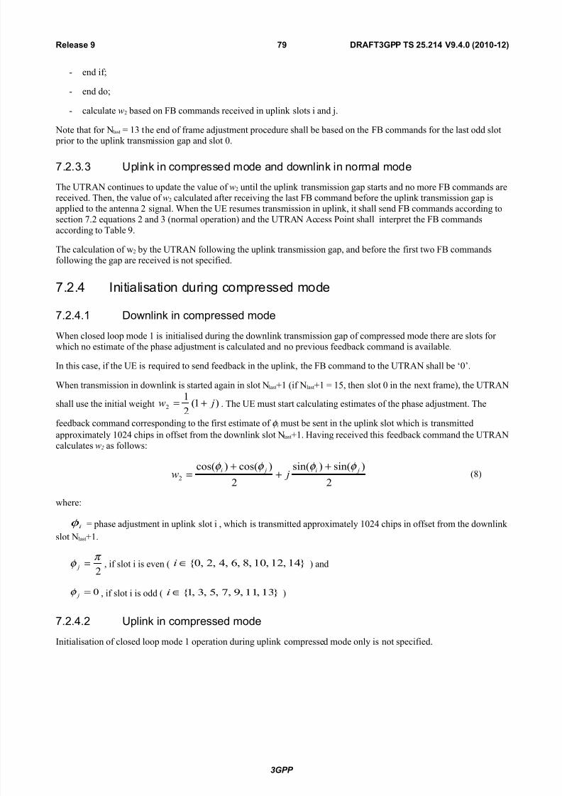
8/18/2019 UTRAN Physical Layer Procedures (FDD)
http://slidepdf.com/reader/full/utran-physical-layer-procedures-fdd 79/99
: end if
: end do
: calculate -* based on 70 commands received in uplin" slots i and j.
&ote that for &last ,3 the end of frame adjustment procedure shall be based on the 70 commands for the last odd slot
prior to the uplin" transmission ap and slot +.
.2.3.3 U$li': i' #o7$re!!ed 7ode a'd do'li': i' 'or7al 7ode
The T/& continues to update the value of -* until the uplin" transmission ap starts and no more 70 commands arereceived. Then- the value of -* calculated after receivin the last 70 command before the uplin" transmission ap isapplied to the antenna * sinal. hen the 2 resumes transmission in uplin"- it shall send 70 commands accordin tosection A.* eDuations * and 3 (normal operation) and the T/& ccess Point shall interpret the 70 commands
accordin to Table C.
The calculation of w* by the T/& followin the uplin" transmission ap- and before the first two 70 commandsfollowin the ap are received is not specified.
.2.4 <'iiali!aio' duri' #o7$re!!ed 7ode
.2.4.1 o'li': i' #o7$re!!ed 7ode
hen closed loop mode , is initialised durin the downlin" transmission ap of compressed mode there are slots forwhich no estimate of the phase adjustment is calculated and no previous feedbac" command is available.
%n this case- if the 2 is reDuired to send feedbac" in the uplin"- the 70 command to the T/& shall be [+\.
hen transmission in downlin" is started aain in slot & lastU, (if &lastU, ,>- then slot + in the ne't frame)- the T/&
shall use the initial weiht ),(*
,* j- += . The 2 must start calculatin estimates of the phase adjustment. The
feedbac" command correspondin to the first estimate of φ i must be sent in the uplin" slot which is transmitted
appro'imately ,+*9 chips in offset from the downlin" slot &lastU,. ;avin received this feedbac" command the T/&calculates -& as followsF
*
)sin()sin(
*
)cos()cos(*
ji ji j-
φ φ φ φ ++
+= (B)
whereF
iφ phase adjustment in uplin" slot i - which is transmitted appro'imately ,+*9 chips in offset from the downlin"
slot &lastU,.
*π φ = j - if slot i is even ( `,9-,*-,+-B-?-9-*-+_∈i ) and
+= j
φ - if slot i is odd ( `,3-,,-C-A->-3-,_∈i )
.2.4.2 U$li': i' #o7$re!!ed 7ode
%nitialisation of closed loop mode , operation durin uplin" compressed mode only is not specified.
3GPP
RAFT3GPP TS #$%#&' "%'%) (#)&)*&#!,"Release "

8/18/2019 UTRAN Physical Layer Procedures (FDD)
http://slidepdf.com/reader/full/utran-physical-layer-procedures-fdd 80/99
.3 Void
B <dle $eriod! or <P" lo#aio' 7e%od
B.1 Ge'eral
To support time difference measurements for location services- idle periods can be created in the downlin" (hence thename %P85) durin which time transmission of all channels from a &ode 0 is temporarily seied. 8urin these idle periods the visibility of neihbour cells from the 2 is improved.
The idle periods are arraned in a predetermined pseudo random fashion accordin to hiher layer parameters. %dle
periods differ from compressed mode in that they are shorter in duration- all channels are silent simultaneously- and noattempt is made to prevent data loss.
%n eneral there are two modes for these idle periodsF
: 1ontinuous mode- and
: 0urst mode.
%n continuous mode the idle periods are active all the time. %n burst mode the idle periods are arraned in bursts where
each burst contains enouh idle periods to allow a 2 to ma"e sufficient measurements for its location to be calculated.The bursts are separated by a period where no idle periods occur.
B.2 Para7eer! o <P"
The followin parameters are sinalled to the 2 via hiher layersF
IP&tatus: This is a loic value that indicates if the idle periods are arraned in continuous or burst mode.
IP&pacing: The number of ,+ ms radio frames between the start of a radio frame that contains an idle period andthe ne't radio frame that contains an idle period. &ote that there is at most one idle period in a radioframe.
IP#ength: The lenth of the idle periods- e'pressed in symbols of the 1P%1;.
IPffset: cell specific offset that can be used to synchronise idle periods from different sectors within a &ode 0.
&eed: !eed for the pseudo random number enerator.
dditionally in the case of burst mode operation the followin parameters are also communicated to the 2.
Burst&tart: !pecifies the start of the first burst of idle periods. *>?×0urst=!tart is the !7& where the first burst ofidle periods starts.
Burst#ength: The number of idle periods in a burst of idle periods.
Burst5re": !pecifies the time between the start of a burst and the start of the ne't burst. *>?×0urst=7reD is the
number of radio frames of the primary 1P%1; between the start of a burst and the start of the ne't burst.
B.3 +al#ulaio' o idle $eriod $o!iio'
%n burst mode- burst Y+ starts in the radio frame with !7& *>?×0urst=!tart. 0urst Yk starts in the radio frame with
!7& *>?×0urst=!tart U k ×*>?×0urst=7reD( k +-,-*- R). The seDuence of bursts accordin to this formula continuesup to and includin the radio frame with !7& 9+C>. t the start of the radio frame with !7& +- the burst seDuence is
terminated (no idle periods are enerated) and at !7& *>?×0urst=!tart the burst seDuence is restarted with burst Y+
followed by burst Y, etc.- as described above.
3GPP
RAFT3GPP TS #$%#&' "%'%) (#)&)*&#!-)Release "

8/18/2019 UTRAN Physical Layer Procedures (FDD)
http://slidepdf.com/reader/full/utran-physical-layer-procedures-fdd 81/99
1ontinuous mode is eDuivalent to burst mode- with only one burst spannin the whole !7& cycle of 9+C? radio frames-this burst startin in the radio frame with !7& +.
ssume that %P=Position( ') is the position of idle period number ' within a burst- where ' ,- *- R- and %P=Position( ')is measured in number of 1P%1; symbols from the start of the first radio frame of the burst.
The positions of the idle periods within each burst are then iven by the followin eDuationF
%P=Position( ') ( ' × %P=!pacin × ,>+) U (rand( ' modulo ?9) modulo (,>+ K %P=5enth)) U %P=Offset
where rand(m) is a pseudo random enerator defined as followsF
rand(+) !eed
rand(m) (,+?×rand(m K ,) U ,*B3) modulo ?+A>- m ,- *- 3- R.
&ote that ' is reset to ' , for the first idle period in every burst.
7iure ? below illustrates the idle periods for the burst mode case.
!lot YnU,!lot Yn
(0urst=5enth)t idle period
%P=5enth
[ ' × %P=!pacin\ frames
%P=Position( ')
%P=Position(,)
'th idle eriod in burst
rand( ' mod ?9) mod (,>+ K %P=5enth) U %P=Offset
[*>?×0urst=7reD\ frames
0urst Y+ of idle periods
7rame Yi
!7& +
[%P=!pacin\ frames
[*>?×0urst=!tart\ frames
0urst Y, of idle periods
[%P=!pacin\ frames
!lot Y+ !lot Y, !lot Y,9
!7& *>?×0urst=!tart
!7& *>?×0urst=!tart U *>?×0urst=7reD
Fi.ure +/ 2dle Period placeent in the case of 1urst ode operation
3GPP
RAFT3GPP TS #$%#&' "%'%) (#)&)*&#!-&Release "

8/18/2019 UTRAN Physical Layer Procedures (FDD)
http://slidepdf.com/reader/full/utran-physical-layer-procedures-fdd 82/99
9 M<M; o$eraio' o 8S-S+8
There are two possibilities for operatin M%MOF M%MO mode when sinle:stream restriction is not confiured- inwhich both sinle and dual stream transmission can be applied- and M%MO mode when sinle:stream restriction isconfiured- which is restricted only to sinle stream transmission. This section applies only when a 2 is confiured inM%MO mode.
The eneral transmitter structure to support M%MO operation of ;!:P8!1; transmission is shown in fiure A. 1hannel
codin- interleavin and spreadin are done as in non:M%MO mode. hen sinle:stream restriction is not confiuredthe &ode 0 scheduler can decide to transmit one or two transport bloc"s to a 2 in one TT% in the servin ;!:8!1;cell- and one or two transport bloc"s in the secondary servin ;!:8!1; cell if the 2 is confiured with a secondaryservin ;!:8!1; cell- whereas when sinle:stream restriction is confiured only transmission of sinle transport bloc" is allowed in any of the cells. The spread comple' valued sinals are fed to both TL antenna branches- and weihtedwith precodin weihts -*- -& , -9 and -=. The precodin weihts -* and -9 are constant real valued scalars and the
precodin weihts -& and -= are variable comple' valued scalars. The precodin weihts -*- -&- -9 and -= are definedas followsF
*<,,3
== -- -
*9 -- −= -
−−+−−+∈
*
,-
*
,-
*
,-
*
,*
j j j j- .
%f sinle:stream restriction is confiured- or sinle:stream restriction is not confiured and the &ode 0 schedules asinle transport bloc" in a cell to a 2 in one TT%- it uses the precodin vector (-*, -&) for transmission of that transport bloc" on the ;!:P8!1; sub:frame. %f sinle:stream restriction is not confiured and the T/& schedules twotransport bloc"s in a cell to a 2 in one TT%- it uses two orthoonal precodin vectors to transmit the two transport
bloc"s. The precodin vector (-*, -&) is called the primary precodin vector which is used for transmittin the primarytransport bloc" and the precodin vector (-9, -=) is called secondary precodin vector which is used for transmittin thesecondary transport bloc"- respectively.
%f sinle:stream restriction is confiured (7iure Aa) the secondary transport bloc" is never present. %f sinle:streamrestriction is not confiured (fiure A) the &ode 0 can dynamically schedule the 2 with one or two transport bloc"s.
3GPP
RAFT3GPP TS #$%#&' "%'%) (#)&)*&#!-#Release "

8/18/2019 UTRAN Physical Layer Procedures (FDD)
http://slidepdf.com/reader/full/utran-physical-layer-procedures-fdd 83/99
Fi.ure ,/ The .eneric downlink transitter structure to support :2: operation for 6S*PS56transission when sin.le*strea restriction is not confi.ured%
Fi.ure ,a/ The .eneric downlink transitter structure to support :2: operation for 6S*PS56transission when sin.le*strea restriction is confi.ured%
3GPP
RAFT3GPP TS #$%#&' "%'%) (#)&)*&#!-3Release "

8/18/2019 UTRAN Physical Layer Procedures (FDD)
http://slidepdf.com/reader/full/utran-physical-layer-procedures-fdd 84/99
9.1 Ge'eral $ro#edure
The 2 uses the 1P%1; to separately estimate the channels seen from each antenna. One of the antennas will transmitthe ntenna , modulation pattern of the P:1P%1; as defined in subclause >.3.3., of H,I. The other antenna will transmiteither the ntenna * modulation pattern of the P:1P%1; or the ntenna , modulation pattern of a !:1P%1;. The Pilotconfiuration in support of M%MO operation of ;!:8!1; in the cell is sinalled by hiher layers.
The 2 determines a preferred primary precodin vector ( pref
*
pref
, - -- and sinals it to the &ode 0. The sinalled
information about the preferred primary precodin vector is termed precodin control indication (P1%) and is defined insubclause ?.9. The P1% is sinalled to the &ode 0 toether with channel Duality indication (1E%) as a compositeP1%<1E% report accordin to the procedure defined in subclause ?.,.*.*. The 2 transmits the composite P1%<1E%report to the &ode 0 usin the 1E% field on the ;!:8P11; as defined in H,I. 0ased on the composite P1%<1E% reports-
the &ode 0 scheduler decides when sinle:stream restriction is not confiured whether to schedule one or two transport bloc"s in a cell to a 2 in one TT% and what transport bloc" sie(s) and modulation scheme(s) to use for each of them.
The &ode 0 sinals to the 2 the precodin weiht -& applied on the ;!:P8!1; sub:frame usin the precodinweiht indication bits of part , of the correspondin ;!:!11; sub:frame. The precodin weiht adjustment of each;!:P8!1; is done at the ;!:P8!1; sub:frame border.
3GPP
RAFT3GPP TS #$%#&' "%'%) (#)&)*&#!-'Release "

8/18/2019 UTRAN Physical Layer Procedures (FDD)
http://slidepdf.com/reader/full/utran-physical-layer-procedures-fdd 85/99
&''e/ & (i'or7aie)('o ile)
&.1 &'e''a erii#aio'
%n closed loop mode ,- if channel estimates are ta"en from the Primary 1P%1;- the performance will also suffer if the2 cannot detect errors since the channel estimates will be ta"en for the incorrect phase settins. To mitiate this problem- antenna verification can be done- which can ma"e use of antenna specific pilot patterns of the dedicated physical channel. The antenna verification can be implemented with several different alorithms. straihtforward
alorithm can use a 9:hypothesis test per slot. lternatively- a simplified beam former verification (!0@) reDuirin onlya *:hypothesis test per slot can be used.
1onsider
{ }
=
=
>∑= )+(
)(
ln)/e(*
,
*
V)(
-*
)(
-*,
* R'
R' p
i
d
i
Npath
i i p
p
hh φ
π φ
γ σ
Then define the variable '+ as + if the above ineDuality holds ood and '+ π otherwise.
!imilarly consider
{ }
−=
=>− ∑
= )*(
)*(ln)%m(*
,*
V)(
-*
)(
-*
,* π φ
π φ γ
σ R'
R' p
i
d
i
Npath
i i p
phh
then define the variable ', as :π<* if the above ineDuality holds ood and ', π<* oherwise.
hether '+ or ', is to be calculated for each slot is iven by the followin table - where the first row contains the 5
slot inde' of the feedbac" bit to be verified.
9 ) & # 3 ' $ + , - " &) && &# &3 &'
/0 /1 /0 /1 /0 /1 /0 /1 /0 /1 /0 /1 /0 /1 /0
The estimate for the transmitted phase is now obtained from
*
)cos(
*
)sin(
)cos()sin(
,
+
,
+
∑∑== +=+ i
i
i
i
T'T'
'
j
'
j φ φ
whereF
: the 'i values are used correspondin to the current slot and the previous slot ta"in into account the end:of:frameadjustment and the used 15 timin adjustment delay
: )(
-*
p
ih is the i#th estimated channel tap of antenna * usin the 1P%1;
: )(
-*
d
ih is the i#th estimated channel tap of antenna * usin the 8P11;
− γ & is the 8P1; Pilot !&%/< 1P%1; !&%/
: *iσ is the noise plus interference power on the i#th path.
3GPP
RAFT3GPP TS #$%#&' "%'%) (#)&)*&#!-$Release "

8/18/2019 UTRAN Physical Layer Procedures (FDD)
http://slidepdf.com/reader/full/utran-physical-layer-procedures-fdd 86/99
%n normal operation the a priori probability for selected pilot pattern is assumed to be C? (assumin there are 9 oferrors in the feedbac" channel for power control and antenna selection).
&.2 +o7$uaio' o eeda#: i'or7aio' or #lo!ed loo$ 7ode1 ra'!7i dier!iy
%n non:soft handover case- the computation of feedbac" information can be accomplished by e.. solvin for weihtvector- -, that ma'imises.
P>- 6 6 6 6- (,)
where
;[h* h&] and w H w,- w* IT
and where the column vectors h* and h& represent the estimated channel impulse responses for the transmission antennas, and *- of lenth eDual to the lenth of the channel impulse response. The elements of w correspond to the adjustmentscomputed by the 2.
8urin soft handover- the antenna weiht vector- - can be- for e'ample- determined so as to ma'imise the criteriafunctionF
P w;(;,;;,U ;*
;;*U⋅⋅⋅⋅)w (*)
where 6 i is an estimated channel impulse response for 0!Yi. %n reular !;O- the set of 0!Yi corresponds to the activeset.
%f ;!:P8!1; is present- the 2 may emphasie the ;!:P8!1; servin cell. %n this case the antenna weiht vector- - can be- for e'ample- determined so as to ma'imise the criteria functionF
P w
;
(α(;,
;
;,)U (,:α)(;*
;
;*U⋅⋅⋅⋅))w
where 0!Y, is the ;!:P8!1; servin cell and coefficient α is less than or eDual to ,. 7or e'ample α +.A enhances
;!:8!1; performance while ensurin that there is only a small deradation on the 8P1;.
3GPP
RAFT3GPP TS #$%#&' "%'%) (#)&)*&#!-+Release "
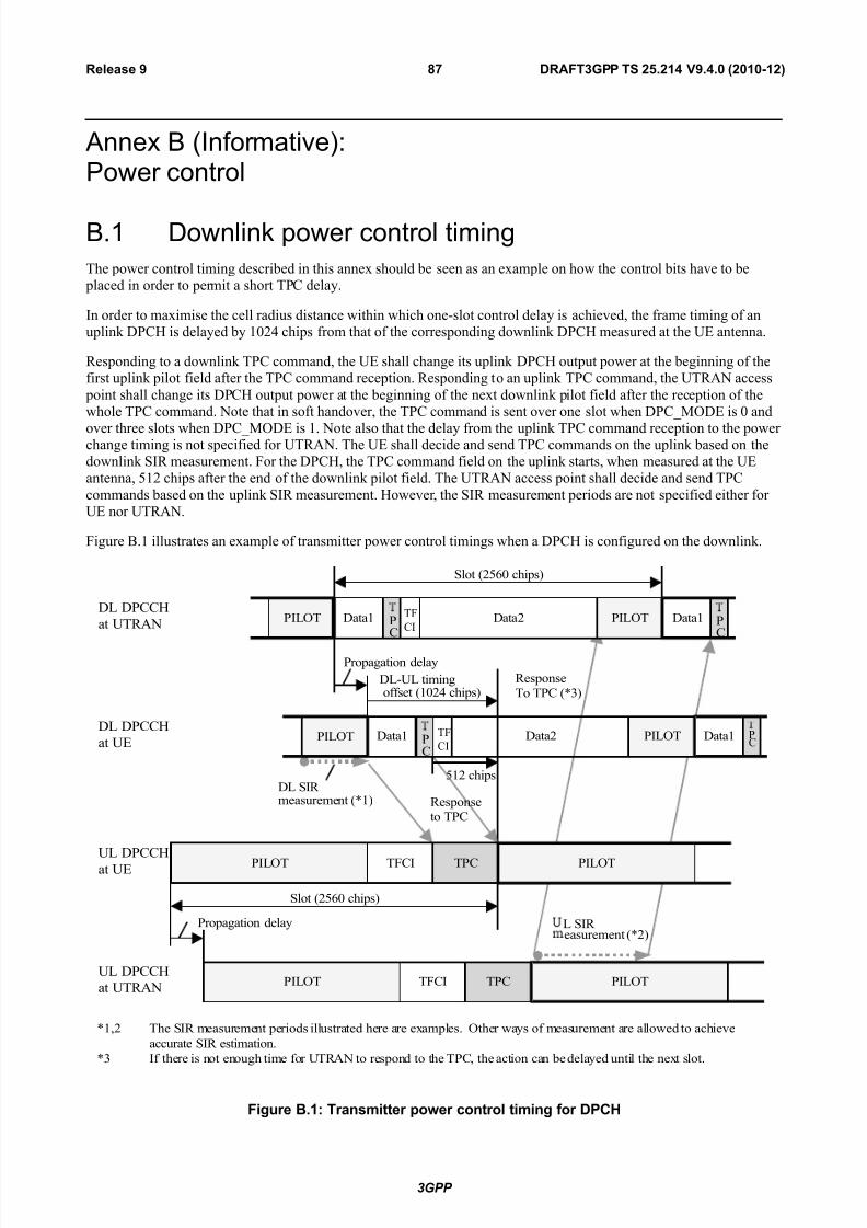
8/18/2019 UTRAN Physical Layer Procedures (FDD)
http://slidepdf.com/reader/full/utran-physical-layer-procedures-fdd 87/99
&''e/ (<'or7aie)Poer #o'rol
.1 o'li': $oer #o'rol i7i'
The power control timin described in this anne' should be seen as an e'ample on how the control bits have to be placed in order to permit a short TP1 delay.
%n order to ma'imise the cell radius distance within which one:slot control delay is achieved- the frame timin of anuplin" 8P1; is delayed by ,+*9 chips from that of the correspondin downlin" 8P1; measured at the 2 antenna.
/espondin to a downlin" TP1 command- the 2 shall chane its uplin" 8P1; output power at the beinnin of thefirst uplin" pilot field after the TP1 command reception. /espondin to an uplin" TP1 command- the T/& access
point shall chane its 8P1; output power at the beinnin of the ne't downlin" pilot field after the reception of thewhole TP1 command. &ote that in soft handover- the TP1 command is sent over one slot when 8P1=MO82 is + and
over three slots when 8P1=MO82 is ,. &ote also that the delay from the uplin" TP1 command reception to the powerchane timin is not specified for T/&. The 2 shall decide and send TP1 commands on the uplin" based on thedownlin" !%/ measurement. 7or the 8P1;- the TP1 command field on the uplin" starts- when measured at the 2antenna- >,* chips after the end of the downlin" pilot field. The T/& access point shall decide and send TP1
commands based on the uplin" !%/ measurement. ;owever- the !%/ measurement periods are not specified either for2 nor T/&.
7iure 0., illustrates an e'ample of transmitter power control timins when a 8P1; is confiured on the downlin".
8ata*8ata,
V,-* The !%/ measurement periods illustrated here are e'amples. Other ways of measurement are allowed to achieve
accurate !%/ estimation.
V3 %f there is not enouh time for T/& to respond to the TP1- the action can be delayed until the ne't slot.
8ata, P1
8ata, P1
P%5OTP%5OT
P%5OT
/esponse
To TP1 (V3)
P1
85 !%/ measurement (V,)
P%5OT T71% TP1
85:5 timin offset (,+*9 chips)
!lot (*>?+ chips)
P%5OTP%5OT 8ata*8ata, P1
P%5OTP%5OT T71% TP1
!lot (*>?+ chips)
Propaation delay
5 !%/ easurement (V*)
/esponse
to TP1
85 8P11;
at T/&
Propaation delay
85 8P11;
at 2
5 8P11;
at T/&
5 8P11;
at 2
>,* chips
T7
1%
T7
1%
Fi.ure 0%&/ Transitter power control tiin. for P56
3GPP
RAFT3GPP TS #$%#&' "%'%) (#)&)*&#!-,Release "

8/18/2019 UTRAN Physical Layer Procedures (FDD)
http://slidepdf.com/reader/full/utran-physical-layer-procedures-fdd 88/99
7iure 0.* illustrates an e'ample of transmitter power control timins when the 7:8P1; is confiured on the downlin"and the 7:8P1; TP1 offset &O77, of all the radio lin"s in the /5! is + or *(see Table ,?1 of H,I). 7iure 0.*a illustratesan e'ample of transmitter power control timins for the radio lin" whose 7:8P1; TP1 offset &O77, + or *- when the7:8P1; is confiured on the downlin"- and the 7:8P1; TP1 offset &O77, of at least one other radio lin" in the /5! is
*. 7iure 0.3 illustrates an e'ample of transmitter power control timins when the 7:8P1; is confiured on thedownlin" and the 7:8P1; TP1 offset &O77, of the radio lin" is larer than *. 7iure 0.9 illustrates an e'ample of
transmitter power control timins when the 7:8P1; is confiured on the downlin" and the 7:8P1; TP1 offset &O77, of the radio lin" is larer than ,9 when uplin" 8P11; slot format Y9 is used.
TP1
TP1
TP1
TP1
P%5OT T71% TP1 P%5OT T71% TP1
P%5OT T71% TP1 P%5OT T71% TP1
/esponse
To TP1
85 !%/easurement
85:5 timinoffset (,+*9 chips)
!lot (*>?+ chips)
Propaation delay τ p
5 !%/easurement
/esponse
o TP1
85 7:8P1;
at T/&
Propaation delay
85 7:8P1;at 2
5 8P11;
at T/&
5 8P11;
at 2
!lot (*>?+ chips)
TP1
τ+
7:8P1;
>,* chips or more &O77,
Fi.ure 0%#/ Transitter power control tiin. for F*P56 with TP5 offsets NFF& of ) or # when F*P56 TP5 offset NFF& of all the radio links in the RS is ) or #
3GPP
RAFT3GPP TS #$%#&' "%'%) (#)&)*&#!--Release "

8/18/2019 UTRAN Physical Layer Procedures (FDD)
http://slidepdf.com/reader/full/utran-physical-layer-procedures-fdd 89/99
P1
TP
1
P1
P1
P%5OT T71% TP1 P%5OT T71% TP1
P%5OT T71% TP1 P%5OT T71% TP1
/esponse
To TP1
85 !%/measurement
85:5 timinoffset (,+*9 chips)
!lot (*>?+ chips)
Propaation delay τ p
5 !%/measurement
/esponse
to TP1
85 7:8P1;at T/&
Propaation delay
85 7:8P1;
at 2
5 8P11;at T/&
5 8P11;
at 2
!lot (*>?+ chips)
TP1
τ+
7:8P1;
>,* chips or more &O77,
Fi.ure 0%#a/ Transitter power control tiin. for F*P56 with TP5 offsets N FF& of ) or # when theF*P56 TP5 offset NFF& of at least one other radio link in the RS is H #
TP1
TP1
TP
1
P%5OT T71% TP1 P%5OT T71% TP1
P%5OT T71% TP1 P%5OT T71% TP1
85 !%/measurement
85:35 timinoffset (,+*9 chips)
!lot (*>?+ chips)
Propaation delay τ p
35 !%/easurement
/esponse
o TP1
85 7:8P1;at 3T/&
Propaation delay
85 7:8P1;
at 32
35 8P11;at 3T/&
35 8P11;at 32
&O77,
!lot (*>?+ chips)τ+
7:8P1;
P%5OT
/esponse
To TP1
TP1
Fi.ure 0%3/ Transitter power control tiin. for F*P56 with a TP5 offset N FF& lar.er than #
3GPP
RAFT3GPP TS #$%#&' "%'%) (#)&)*&#!-"Release "

8/18/2019 UTRAN Physical Layer Procedures (FDD)
http://slidepdf.com/reader/full/utran-physical-layer-procedures-fdd 90/99
TP
1
TP
1
TP
1
TP
1
TP
1
P%5OT TP1 P%5OT TP1
P%5OT TP1 P%5OT TP1
85 !%/measurement
85:35 timinoffset (,+*9 chips)
!lot (*>?+ chips)
Propaation delay τ p
35 !%/measurement
/esponse
to TP1
85 7:8P1;at 3T/.&
Propaation delay
85 7:8P1;
at 32
35 8P11;at 3T/.&
35 8P11;
at 32
&O77,
!lot (*>?+ chips)τ+
7:8P1;
P%5OT TP1
P%5OT TP1
/esponse
to TP1
Fi.ure 0%'/ Transitter power control tiin. for F*P56 with a TP5 offset N FF& lar.er than &' withuplink P556 slot forat '
.2 /a7$le o i7$le7e'aio' i' %e U
The downlin" inner:loop power control adjusts the networ" transmit power in order to "eep the received downlin" !%/at a iven !%/ taret- !%/ taret. hiher layer outer loop adjusts !%/ taret independently for each connection.
The 2 should estimate the received downlin" 8P11;<8P81; power of the connection to be power controlled.!imultaneously- the 2 should estimate the received interference and calculate the sinal:to:interference ratio- !%/ est.!%/ est can be calculated as /!1P<%!1P- where /!1P refers to the received sinal code power on one code and %!1Prefers to the non:orthoonal interference sinal code power of the received sinal on one code. &ote that due to thespecific !%/ taret offsets described in H>I that can be applied durin compressed frames- the spreadin factor shall not
be considered in the calculation of !%/ est.
The obtained !%/ estimate !%/ est is then used by the 2 to enerate TP1 commands accordin to the followin ruleF if!%/ est !%/ taret then the TP1 command to transmit is J+J- reDuestin a transmit power decrease- while if !%/ est Q !%/ taret
then the TP1 command to transmit is J,J- reDuestin a transmit power increase.
hen the 2 is in soft handover- the 2 should estimate !%/ est from the downlin" sinals of all cells in the active set.
.3 U" $oer #o'rol %e' lo!i' U" !y'#%ro'i!aio'
2ach &ode 0 operates the uplin" power control independently of the other &ode 0s that may be providin /5! to thesame 2. %n case of multiple /5! the 2 derives the decision on power adjustment based on all the commands
received accordin the rules specified in section >.,.*. %n this scenario- transmission of a down command by one ormore of the involved &ode 0s will li"ely result in the 2 decreasin its transmit power.
3GPP
RAFT3GPP TS #$%#&' "%'%) (#)&)*&#!")Release "

8/18/2019 UTRAN Physical Layer Procedures (FDD)
http://slidepdf.com/reader/full/utran-physical-layer-procedures-fdd 91/99
1onseDuently- if and when- after successful initial /5 synchronisation- the &ode 0 loses 5 synchronisation for a 2and if the current number of /5! confiured for that 2 is reater than one and if the &ode 0 reverts to a TP1 patternin such situation (i.e. enerates 85 TP1 commands independently of actual /5 measurements)- the &ode 0 should notuse TP1 commands S+ in the TP1 pattern.
3GPP
RAFT3GPP TS #$%#&' "%'%) (#)&)*&#!"&Release "
8/18/2019 UTRAN Physical Layer Procedures (FDD)
http://slidepdf.com/reader/full/utran-physical-layer-procedures-fdd 92/99
&''e/ + (<'or7aie)+ell !ear#% $ro#edure
8urin the cell search- the 2 searches for a cell and determines the downlin" scramblin code and framesynchronisation of that cell. The cell search is typically carried out in three stepsF
Se$ 1 Slo !y'#%ro'i!aio'
8urin the first step of the cell search procedure the 2 uses the !1;\s primary synchronisation code to acDuire slot
synchronisation to a cell. This is typically done with a sinle matched filter (or any similar device) matched to the primary synchronisation code which is common to all cells. The slot timin of the cell can be obtained by detectin pea"s in the matched filter output.
Se$ 2 ra7e !y'#%ro'i!aio' a'd #ode-rou$ ide'ii#aio'
8urin the second step of the cell search procedure- the 2 uses the !1;\s secondary synchronisation code to find
frame synchronisation and identify the code roup of the cell found in the first step. This is done by correlatin thereceived sinal with all possible secondary synchronisation code seDuences- and identifyin the ma'imum correlationvalue. !ince the cyclic shifts of the seDuences are uniDue the code roup as well as the frame synchronisation isdetermined.
Se$ 3 S#ra7li'-#ode ide'ii#aio'
8urin the third and last step of the cell search procedure- the 2 determines the e'act primary scramblin code used by the found cell. The primary scramblin code is typically identified throuh symbol:by:symbol correlation over the
1P%1; with all codes within the code roup identified in the second step. fter the primary scramblin code has beenidentified- the Primary 11P1; can be detected. nd the system: and cell specific 01; information can be read.
%f the 2 has received information about which scramblin codes to search for- steps * and 3 above can be simplified.
3GPP
RAFT3GPP TS #$%#&' "%'%) (#)&)*&#!"#Release "

8/18/2019 UTRAN Physical Layer Procedures (FDD)
http://slidepdf.com/reader/full/utran-physical-layer-procedures-fdd 93/99
&''e/ (i'or7aie)+%a'e %i!ory
3GPP
RAFT3GPP TS #$%#&' "%'%) (#)&)*&#!"3Release "

8/18/2019 UTRAN Physical Layer Procedures (FDD)
http://slidepdf.com/reader/full/utran-physical-layer-procedures-fdd 94/99
5han.e history
ae TSG C TSG o#. +R Re Su>e#+o77e' ;ld *eR&*=05 RP-99531 - &$$roed a TSG R&* C5 a'd $la#ed u'der +%a'e +o'rol - 3.0.0
140100 R&*=06 RP-996B6 003 2 le/ile i7i' o UTR&* re!$o'!e o u$li': #lo!ed loo$ T/dier!iy eeda#: #o77a'd!
3.0.0 3.1.0
140100 R&*=06 RP-996B6 006 2 +P+8 $oer #o'rol $rea7le le'% 3.0.0 3.1.0
140100 R&*=06 RP-996B6 00 - Re7oal o o$e' loo$ $oer #o'rol 3.0.0 3.1.0
140100 R&*=06 RP-996B 00B - Poer o!e o &<+8 a'd P<+8 3.0.0 3.1.0140100 R&*=06 RP-996B6 009 1 U$dae o Ra'do7 &##e!! Pro#edure 3.0.0 3.1.0
140100 R&*=06 RP-996B6 010 1 o !y7ol #o7i'i' or u$li': $oer #o'rol 3.0.0 3.1.0
140100 R&*=06 RP-996B5 011 - +larii#aio' o #lo!ed loo$ ra'!7i dier!iy iure i' #lau!e B a'd#lo!ed loo$ o$eraio' i' #o7$re!!ed 7ode or 7ode 2 i'!u#lau!e B.3 o TS 25.214
3.0.0 3.1.0
140100 R&*=06 RP-996B6 012 - U$li': $oer #o'rol 7a/i7u7 TE $oer 3.0.0 3.1.0
140100 R&*=06 RP-996B6 013 1 Sei' o ea alue! or 7uli-#ode 3.0.0 3.1.0
140100 R&*=06 RP-996B6 014 - +o'!olidaio' o +P+8 Poer +o'rol Prea7le <'or7aio' 3.0.0 3.1.0
140100 R&*=06 RP-996B6 015 1 +o'!ol idaio' o Poer +o'rol <'or7aio' or +8 <'iiali!aio' 3.0.0 3.1.0
140100 R&*=06 RP-996B6 016 - U$li': $oer #o'rol i' #o7$re!!ed 7ode 3.0.0 3.1.0
140100 R&*=06 RP-996B6 01B 1 Ti7i' or i'iiali!aio' $ro#edure! 3.0.0 3.1.0
140100 R&*=06 RP-996B 021 - 20 7! R&+8 7e!!ae le'% 3.0.0 3.1.0
140100 R&*=06 RP-996B4 023 1 Ma/i7u7 T/ Poer a u$li': #o7$re!!ed Mode 3.0.0 3.1.0
140100 R&*=06 RP-996B 024 2 Sei' o $oer i' u$li': #o7$re!!ed 7ode 3.0.0 3.1.0
140100 R&*=06 RP-996B 025 - +lea'u$ o !y'#%ro'i!aio' $ro#edure! 3.0.0 3.1.0140100 R&*=06 RP-996B6 026 2 o'li': $oer #o'rol 3.0.0 3.1.0
140100 R&*=06 RP-996B 029 - ;u-o-!y'#% %a'dli' 3.0.0 3.1.0
140100 R&*=06 RP-996B 030 2 Sae u$dae rule addiio' o SST !$e#ii#aio' 3.0.0 3.1.0
140100 R&*=06 RP-996B 033 - U$li': TE i7i' ad>u!7e' 3.0.0 3.1.0
140100 R&*=06 RP-996B 036 - <'#lu!io' o idle $eriod! or %e <P" "+S 3.0.0 3.1.0
140100 R&*=06 RP-996B6 041 - Rei!io' o $oer #o'rol i7i' e/ 3.0.0 3.1.0
140100 R&*=06 RP-996B 042 1 <'#lu!io' o ad>u!7e' loo$ i' do'li': $oer #o'rol 3.0.0 3.1.0
140100 - - - +%a'e %i!ory a! added y %e edior 3.1.0 3.1.1
310300 R&*=0 RP-000064 043 1 ;$i7u7 < +ode! or SST Poer +o'rol 3.1.1 3.2.0
310300 R&*=0 RP-000064 044 - diorial #larii#aio' o !u#lau!e 5.1.2.2.2 3.1.1 3.2.0
310300 R&*=0 RP-000064 04 1 &ddiio'al de!#ri$io' o TE dier!iy or PS+8 3.1.1 3.2.0
310300 R&*=0 RP-000064 04B - Poer o!e o' S-++P+8 3.1.1 3.2.0
310300 R&*=0 RP-000064 050 2 +orre#io'! o u$li': $oer #o'rol 3.1.1 3.2.0
310300 R&*=0 RP-000064 055 - +orre#io' o &d>u!7e' loo$ de!#ri$io' 3.1.1 3.2.0
310300 R&*=0 RP-000064 056 1 +larii#aio' o TP+ #o77a'd #o7i'i' or &lori%7 1 3.1.1 3.2.0310300 R&*=0 RP-000064 05 - +larii#aio' o TP+ #o77a'd #o7i'i' or &lori%7 2 3.1.1 3.2.0
310300 R&*=0 RP-000064 059 2 +P+8+ !u!lo-relaed addiio'! o 6.2 3.1.1 3.2.0
310300 R&*=0 RP-000064 061 1 +P+8 ediorial #%a'e! a'd #larii#aio'! o 6.2 3.1.1 3.2.0
310300 R&*=0 RP-000064 062 - diorial #orre#io'! 3.1.1 3.2.0
310300 R&*=0 RP-000064 064 1 diorial i7$roe7e' o %e <P" !e#io' 3.1.1 3.2.0
310300 R&*=0 RP-000064 065 1 PR&+8 $oer o!e dei'iio' 3.1.1 3.2.0
310300 R&*=0 RP-000064 066 1 Radio li': !y'#%ro'i!aio' i' UTR& 3.1.1 3.2.0
310300 R&*=0 RP-000064 06B - ei'iio' or 7a/i7u7 a'd 7i'i7u7 " $oer 3.1.1 3.2.0
310300 R&*=0 RP-000064 069 4 +%a''el a!!i'7e' a'd U #%a''el !ele#io' 7e%od! o +P+8 3.1.1 3.2.0
310300 R&*=0 RP-000064 01 - +%a''eli@aio' #ode allo#aio' 7e%od or P+P+8 7e!!ae $ar 3.1.1 3.2.0
310300 R&*=0 RP-000064 02 1 "i7ied $oer rai!e u!ed -$ara7eer i' " P+ 3.1.1 3.2.0
310300 R&*=0 RP-000064 0B0 - o'li': $oer #o'rol 3.1.1 3.2.0
310300 R&*=0 RP-000064 0B1 - diorial i7$roe7e' o' SST $oer #o'rol !e#io' 3.1.1 3.2.0
310300 R&*=0 RP-000065 0B2 2 7ere'#y So$ o +P+8 ra'!7i!!io' a'd Sar o Me!!ae
<'di#aor
3.1.1 3.2.0
310300 R&*=0 RP-000065 0B3 - +lea' u$ o USTS relaed !$e#ii#aio'! 3.1.1 3.2.0
260600 R&*=0B RP-00026B 0B4 - &ddiio' o +S<+8 $oer $ara7eer 3.2.0 3.3.0
260600 R&*=0B RP-00026B 0B5 - +orre#io' o $oer #o'rol i' #o7$re!!ed 7ode re#oery $eriod 3.2.0 3.3.0
260600 R&*=0B RP-00026B 0B6 1 Rei!io'! o $oer #o'rol or +P+8 3.2.0 3.3.0
260600 R&*=0B RP-00026B 0B - +orre#io'! o u$li': +8 $oer #o'rol !e#io'! 3.2.0 3.3.0
260600 R&*=0B RP-00026B 090 3 "eel o !$e#ii#aio' o do'li': $oer #o'rol 3.2.0 3.3.0
260600 R&*=0B RP-00026B 091 1 +larii#aio' o TE dier!iy $oer !ei' 3.2.0 3.3.0
260600 R&*=0B RP-00026B 092 - P<+8 u'dei'ed i! 3.2.0 3.3.0
260600 R&*=0B RP-00026B 095 1 P+8P++8 ai' a#or! 3.2.0 3.3.0
260600 R&*=0B RP-00026B 096 3 +orre#io' o R&+8 !u#%a''el dei'iio' 3.2.0 3.3.0
260600 R&*=0B RP-00026B 09 1 T%e $oer !ei' o %e +++ ield o " P++8 or +P+8 3.2.0 3.3.0
260600 R&*=0B RP-00026B 09B 4 Pro#edure or e'd o ra'!7i!!io' i'di#aor i' +P+8 3.2.0 3.3.0
260600 R&*=0B RP-00026B 099 - o'li': i''er-loo$ $oer #o'rol i' #o7$re!!ed 7ode 3.2.0 3.3.0
260600 R&*=0B RP-00026B 100 - ei'iio' o e#or ra'!7i!!io' ei% e'iy 3.2.0 3.3.0
260600 R&*=0B RP-00026B 101 1 *u7er o !lo! or P++8 $oer #o'rol $rea7le 3.2.0 3.3.0260600 R&*=0B RP-00026B 102 - +larii#aio' o UTR&* T/ dier!iy re!$o'!e i7i' de!#ri$io' i'
25.2143.2.0 3.3.0
260600 R&*=0B RP-00026B 103 2 +orre#io'! o ra'!7i dier!iy !e#io' 3.2.0 3.3.0
3GPP
RAFT3GPP TS #$%#&' "%'%) (#)&)*&#!"'Release "

8/18/2019 UTRAN Physical Layer Procedures (FDD)
http://slidepdf.com/reader/full/utran-physical-layer-procedures-fdd 95/99
5han.e history
ae TSG C TSG o#. +R Re Su>e#+o77e' ;ld *e260600 R&*=0B RP-00026B 104 1 +orre#io'! o u$li': $oer #o'rol i' #o7$re!!ed 7ode 3.2.0 3.3.0
260600 R&*=0B RP-00026B 105 - +larii#aio' o do'li': $oer #o'rol 7ode 3.2.0 3.3.0
260600 R&*=0B RP-00026B 106 - +larii#aio' o radio li': !e 3.2.0 3.3.0
260600 R&*=0B RP-00026B 10 1 +larii#aio' o radio li': !y'#%ro'i!aio' $ro#edure 3.2.0 3.3.0
260600 R&*=0B RP-000269 10B - +orre#ly Aua'i@ed ai' a#or! or u$li': #o7$re!!ed 7ode 3.2.0 3.3.0
230900 R&*=09 RP-000342 110 4 o'li': i''er-loo$ $oer #o'rol i' #o7$re!!ed 7ode 3.3.0 3.4.0230900 R&*=09 RP-000342 112 - &ddi' reere'#e or $oer o!e ariaio' e/ i' TS 25.214 3.3.0 3.4.0
230900 R&*=09 RP-000342 113 - +o7i'i' TP+ #o77a'd! i' !o %a'doer 3.3.0 3.4.0
230900 R&*=09 RP-000342 115 1 +orre#io'! o $oer #o'rol 3.3.0 3.4.0
230900 R&*=09 RP-000342 116 - +orre#io'! o 25.214 3.3.0 3.4.0
230900 R&*=09 RP-000342 11 - +larii#aio' o do'li': $oer #o'rol 3.3.0 3.4.0
230900 R&*=09 RP-000342 11B 3 +larii#aio' o $oer #o'rol a 7a/i7u7 a'd 7i'i7u7 $oer 3.3.0 3.4.0
230900 R&*=09 RP-000342 119 - +larii#aio' o SST e/ 3.3.0 3.4.0
230900 R&*=09 RP-000342 120 - +orre#io'! o +" ra'!7i dier!iy 7ode 1 3.3.0 3.4.0
230900 R&*=09 RP-000342 121 1 +larii#aio' o SST < #ode i ra'!7i!!io' order 3.3.0 3.4.0
230900 R&*=09 RP-000342 122 1 +larii#aio' o' R&+8 a'd +P+8 !u#%a''el dei'iio' 3.3.0 3.4.0
230900 R&*=09 RP-000342 123 1 P+8 i'iiali!aio' $ro#edure 3.3.0 3.4.0
230900 R&*=09 RP-000342 124 - +larii#aio' o #lo!ed loo$ 7ode TE dier!iy i'iiali!aio' 3.3.0 3.4.0
230900 R&*=09 RP-000342 12 2 U$li': $oer #o'rol i' #o7$re!!ed 7ode 3.3.0 3.4.0
151200 R&*=10 RP-000540 12B 1 +larii#aio' o do'li': Aualiy 7ea!ure7e' i' SST 3.4.0 3.5.0
151200 R&*=10 RP-000540 129 - or7ula y$ora$%y a'd reere'#e #orre#io'! 3.4.0 3.5.0151200 R&*=10 RP-000540 130 1 Radio li': e!ali!%7e' a'd !y'# !au! re$ori' 3.4.0 3.5.0
151200 R&*=10 RP-000540 133 - +orre#io' o R&+8+P+8 $%y!i#al ra'do7 a##e!! $ro#edure 3.4.0 3.5.0
151200 R&*=10 RP-000540 134 - +orre#io' o u$li': $oer #o'rol alori%7 2 3.4.0 3.5.0
151200 R&*=10 RP-000540 135 1 TP+ #o77a'd e'eraio' o' do'li': duri' R"S i'iiali@aio' 3.4.0 3.5.0
151200 R&*=10 RP-000540 136 1 +lari i#aio' o R&+8 e%aior a 7a/i7u7 a'd 7i'i7u7 $oer 3.4.0 3.5.0
151200 R&*=10 RP-000540 13 - +larii#aio'! o' %e de!#ri$io' o %e radio li': e!ali!%7e'$ro#edure (%e' 'o radio li': e/i!!)
3.4.0 3.5.0
151200 R&*=10 RP-000540 13B 1 +orre#io'! o' $oer #o'rol $rea7le! 3.4.0 3.5.0
151200 R&*=10 RP-000540 139 1 +larii#aio' o R&+8 $ro#edure 3.4.0 3.5.0
151200 R&*=10 RP-000540 140 - U$li': $oer #o'rol i' #o7$re!!ed 7ode 3.4.0 3.5.0
151200 R&*=10 RP-000540 141 1 Rei!io' o %e areiaio' li! 3.4.0 3.5.0
160301 R&*=11 - - - &$$roed a! Relea!e 4 !$e#ii#aio' (4.0.0) a TSG R&* C11 3.5.0 4.0.0
160301 R&*=11 RP-010060 142 1 U$li': $oer #o'rol i' #o7$re!!ed 7ode 3.5.0 4.0.0
160301 R&*=11 RP-010060 144 - Re7oal o %e $oer ala'#i' alori%7 ro7 TS 25.214 3.5.0 4.0.0
160301 R&*=11 RP-010254 145 2 +larii#aio' o *id $ara7eer I %e' SST a'd u$li':#o7$re!!ed 7ode are i' o$eraio'
3.5.0 4.0.0
160301 R&*=11 RP-010060 146 - +larii#aio' o #lo!ed loo$ ra'!7i dier!iy 7ode 1 a'd 7ode 2o$eraio' duri' #o7$re!!ed 7ode
3.5.0 4.0.0
160301 R&*=11 RP-010060 14B 1 +larii#aio' o U S<R e!i7aio' 3.5.0 4.0.0
160301 R&*=11 RP-010060 150 1 +larii#aio' o %e order o SST !i'alli' i' 2 i < 3.5.0 4.0.0
160301 R&*=11 RP-010244 154 2 U$li': $oer #o'rol $rea7le 3.5.0 4.0.0
160301 R&*=11 RP-010060 155 - +orre#io' o li7ied $oer rai!e 3.5.0 4.0.0
160301 R&*=11 RP-010060 156 - +larii#aio' o i'iiali@aio' $ro#edure 3.5.0 4.0.0
160301 R&*=11 RP-010060 15B - ei'iio' o $oer #o'rol !e$ !i@e or alori%7 2 3.5.0 4.0.0
160301 R&*=11 RP-010060 161 1 +orre#io' o %e U e%aior i' SST 7ode 3.5.0 4.0.0
160301 R&*=11 RP-010060 163 - +orre#io' o' do'li': !y'#%ro'i@aio' $ri7iie! 3.5.0 4.0.0
160301 R&*=11 RP-01004 149 1 S+8 Poer +o'rol <7$roe7e' i' !o %a'doer 3.5.0 4.0.0
150601 R&*=12 RP-010334 166 1 "i7ied $oer rai!e ali'i' o er7i'oloy i% TS25.433 4.0.0 4.1.0
150601 R&*=12 RP-010334 16 1 +orre#io' o <P" ur! $ara7eer! 4.0.0 4.1.0
150601 R&*=12 RP-010334 169 1 +orre#io' o !y'#%ro'i!aio' $ri7iie! 4.0.0 4.1.0150601 R&*=12 RP-010334 1 1 +larii#aio' o' TP+ #o77a'd e'eraio' o' do'li': duri' R"
i'iiali!aio'4.0.0 4.1.0
150601 R&*=12 RP-0104B2 1B1 4 +larii#aio' o !y'#%ro'i!aio' $ro#edure! 4.0.0 4.1.0
150601 R&*=12 RP-010334 1B3 - +larii#aio' o i'iiali!aio' o #lo!ed loo$ 7ode 1 a'd 2 duri'#o7$re!!ed 7ode
4.0.0 4.1.0
150601 R&*=12 RP-010334 1B6 - " 7a/i7u7 $oer leel i' #o7$re!!ed 7ode 4.0.0 4.1.0
150601 R&*=12 RP-010341 164 1 +larii#aio' o' %e u!ae o SST !i'ali' i' u$li': 4.0.0 4.1.0
210901 R&*=13 RP-010520 192 - +orre#io'! a'd +larii#aio'! or #al#ulaio' o idle $eriod $o!iio'i' !u#lau!e B.3 i' 25.214
4.1.0 4.2.0
210901 R&*=13 RP-010520 194 1 Mi'or 7odii#aio'! o %e +P+8 a##e!! $ro#edure 4.1.0 4.2.0
210901 R&*=13 RP-010520 19 - o'li': $oer #o'rol i' #o7$re!!ed 7ode 4.1.0 4.2.0
210901 R&*=13 RP-010520 199 1 <7$roe7e'! o #lo!ed loo$ TE dier!iy de!#ri$io' 4.1.0 4.2.0
210901 R&*=13 RP-010520 201 1 +orre#io' o Ra'do7 a##e!! $ro#edure (Pri7iie ro7 M&+) 4.1.0 4.2.0
210901 R&*=13 RP-0106 205 1 Pro$o!ed +R o TS25.214 +larii#aio' o %e SST e%aiour
i% ea7 or7i'
4.1.0 4.2.0
210901 R&*=13 RP-01052 195 1 '%a'#ed PS+8 $oer #o'rol #larii#aio' 4.1.0 4.2.0
141201 R&*=14 RP-01039 20 1 Poer #o'rol i' #o7$re!!ed 7ode %e' P+=M;?1 4.2.0 4.3.0
141201 R&*=14 RP-01039 209 - +larii#aio' o #lo!ed loo$ 7ode 1 a'd 2 T/ dier!iy o$eraio'duri' #o7$re!!ed 7ode
4.2.0 4.3.0
3GPP
RAFT3GPP TS #$%#&' "%'%) (#)&)*&#!"$Release "

8/18/2019 UTRAN Physical Layer Procedures (FDD)
http://slidepdf.com/reader/full/utran-physical-layer-procedures-fdd 96/99
5han.e history
ae TSG C TSG o#. +R Re Su>e#+o77e' ;ld *e141201 R&*=14 RP-01039 211 - o'li': $%a!e reere'#e re#o'iuraio' 4.2.0 4.3.0
141201 R&*=14 RP-01039 219 1 o'li': $oer #o'rol or #%a''el! !u$$ori' +P+8 4.2.0 4.3.0
141201 R&*=14 RP-01039 223 - Re7oal o !lo $oer #o'rol ro7 TS 25.214 4.2.0 4.3.0
141201 R&*=14 RP-0105 216 - U$li': TP+ #o77a'd $ro#e!!i' i' S8; i% SST 4.2.0 4.3.0
141201 R&*=14 RP-01044 21 2 S+8 $oer #o'rol #larii#aio' 4.2.0 4.3.0
141201 R&*=14 RP-010933 229 - Re!ri# io' o SST a'd #lo!ed loo$ 7ode ra'!7i dier!iy#o7i'aio'
4.2.0 4.3.0
0B0302 R&*=15 RP-02004 22 - +larii#aio' o' P++8 dedi#aed $ilo i! i% #lo!ed loo$7ode1
4.3.0 4.4.0
0B0302 R&*=15 RP-020261 231 3 D% %re!%old $ara7eer i' SST 4.3.0 4.4.0
0B0302 R&*=15 RP-02004 240 1 TP+ $ro#edure i' U %e' SST i! a#iaed 4.3.0 4.4.0
0B0302 R&*=15 RP-020053 236 1 +lari i#aio' o #lo!ed loo$ ra'!7i dier!iy duri' !o %a'doer 4.3.0 4.4.0
0B0302 R&*=15 RP-020054 250 1 e!#ri$io' o SST o$eraio' or T+< $oer #o'rol i' %ard !$li7ode
4.3.0 5.0.0
0B0302 R&*=15 RP-02005B 23 2 <'rodu#io' o 8SP& eaure o TS25.214 4.3.0 5.0.0
0B0302 R&*=15 RP-02005B 251 - <'rodu#io' o $oer #o'rol a!$e#! or 8SP& eaure i'TS25.214
4.3.0 5.0.0
00602 R&*=16 RP-020316 255 2 +orre#io' o' %e o$eraio' o 8SP& duri' #o7$re!!ed 7ode 5.0.0 5.1.0
00602 R&*=16 RP-020316 259 1 +larii#aio' o U ra'!7i!!io' i7i' ad>u!7e' i% 8S-P++8 5.0.0 5.1.0
00602 R&*=16 RP-020316 260 4 ei'iio' o +D< re$ori' 5.0.0 5.1.0
00602 R&*=16 RP-020316 266 - +orre#io' o %e !ei' o P++88S-P++8 $oer diere'#e 5.0.0 5.1.000602 R&*=16 RP-020316 26 - <'#lu!io' o +D< ale 5.0.0 5.1.0
00602 R&*=16 RP-02031B 265 1 ei'iio' o D% %re!%old $ara7eer i' SST 5.0.0 5.1.0
10902 R&*=1 RP-0205B4 263 - +larii#aio' o oal 8S-S++88S-PS+8 $oer 5.1.0 5.2.0
10902 R&*=1 RP-02051 22 - Reer!al o u'a'ed #orre#io'! re!uli' ro7 +R 25.211-122 J+R 25.214-226
5.1.0 5.2.0
10902 R&*=1 RP-0205B4 23 2 +lari i#aio' o oal 8S-PS+8 $oer i' +D< re$ori' $ro#edure 5.1.0 5.2.0
10902 R&*=1 RP-0205B4 24 1 +lo!ed loo$ ra'!7i dier!iy 7ode 2 i% a'e''a erii#aio' 5.1.0 5.2.0
10902 R&*=1 RP-0205B9 29 - +orre#io' o 7a/i7u7 $oer ad>u!7e' i' #a!e o #o7$re!!ed7ode
5.1.0 5.2.0
10902 R&*=1 RP-02054 2B2 1 '%a'#ed S+8 $oer #o'rol $ara7eer 'a7e #%a'e 5.1.0 5.2.0
10902 R&*=1 RP-0205B4 2B 2 +orre#io' o +D< dei'iio' 5.1.0 5.2.0
10902 R&*=1 RP-0205B 2BB - <'#lu!io' o #lo!ed loo$ ra'!7i dier!iy or 8SP& 5.1.0 5.2.0
10902 R&*=1 RP-0205BB 2B9 - +orre#io' o i7i' o +D< re$ori' 5.1.0 5.2.0
10902 R&*=1 RP-020529 294 - +orre#io' o reere'#e li':ed o a$$roal o +R 25.133-41 5.1.0 5.2.0
10902 R&*=1 RP-0205B4 296 - T%e #larii#aio' o +D< eeda#: $ara7eer : alue 5.1.0 5.2.010902 R&*=1 RP-0205B4 29B - +larii#aio' o +D< dei'iio' a'd reere'#e $eriod 5.1.0 5.2.0
10902 R&*=1 RP-0205B4 2B6 1 *u7eri' #orre#io'! 5.1.0 5.2.0
201202 R&*=1B RP-020B4 300 1 +orre#io'! a'd #larii#aio'! o +D< de!#ri$io' 5.2.0 5.3.0
201202 R&*=1B RP-020B4 301 1 +rierio' o deer7i'e $ri7ary #ell or S+8 $oer #o'roli7$roe7e'
5.2.0 5.3.0
201202 R&*=1B RP-020B51 304 2 <'rodu#io' o Tra'!$or lo#: Si@e !i'ali' $ro#edurereere'#e.
5.2.0 5.3.0
201202 R&*=1B RP-020B41 30 - +larii#aio' o #lo!ed loo$ i7i' ad>u!7e' 7ode 5.2.0 5.3.0
260303 R&*=19 RP-030136 299 5 +D< re$ori' i% T/ 5.3.0 5.4.0
260303 R&*=19 RP-030136 313 1 ;' #lo!ed loo$ ra'!7i dier!iy 7ode 1 erii#aio' alori%7 5.3.0 5.4.0
260303 R&*=19 RP-030136 315 2 +larii#aio' o SST a'd 8SP& 5.3.0 5.4.0
260303 R&*=19 RP-030132 31B - +orre#io' o' erii#aio' alori%7 i' &''e/ 1 5.3.0 5.4.0
23K0603 R&*=20 RP-03023 314 1 +orre#io' o TP+ #o77a'd #o7i'i' i' S8; 5.4.0 5.5.0
23K0603 R&*=20 RP-03023 319 - +orre#io' or 8S-P++8 ai' a#or i' #o7$re!!ed ra7e 5.4.0 5.5.0
23K0603 R&*=20 RP-03023 320 1 +larii#aio' o 8S-S++8 re#e$io' i' #a!e o 7i'i7u7 i'erTT<i'eral i! 'o 1 5.4.0 5.5.0
23K0603 R&*=20 RP-03023 321 - +orre#io' o de!#ri$io' o +D< ra'!7i!!io' i7i' #al#ulaio' 5.4.0 5.5.0
23K0603 R&*=20 RP-03023 322 1 +larii#aio' o %e reere'#e $oer or 8S-P++8 5.4.0 5.5.0
210903 R&*=21 RP-03045B 325 - +orre#io' o +D< dei'iio' ale 5.5.0 5.6.0
210903 R&*=21 RP-030462 326 - Re7oal o %e #o7i'aio' o T/&& Mode 1 i% 8S-S++8 5.5.0 5.6.0
210903 R&*=21 RP-03045B 32B 2 +larii#aio' o $oer !#ali' i% 8S-P++8 5.5.0 5.6.0
210903 R&*=21 RP-03045B 329 3 +orre#io' o +D< re$ori' i' " #o7$re!!ed 7ode 5.5.0 5.6.0
210903 R&*=21 RP-03045B 330 1 +larii#aio' o 8S-S++8 re#e$io' 5.5.0 5.6.0
210903 R&*=21 RP-03045B 333 1 +larii#aio' o' +D< re$eiio' e%aiour 5.5.0 5.6.0
210903 R&*=21 RP-03054 335 3 TP+ $aer' duri' lo!! o R" !y'#%ro'i!aio' 5.5.0 5.6.0
060104 R&*=22 RP-030649 335 1 +larii#aio' o 8S-S++8 re#e$io' 5.6.0 5..0
060104 R&*=22 RP-030649 336 1 +larii#aio' o +D< dei'iio' 5.6.0 5..0
060104 R&*=22 RP-030649 33 1 +larii#aio' o %e 8S-S++8 dee#io' 5.6.0 5..0
060104 R&*=22 RP-030661 33B - Re7oe i'#o'!i!e'#y a7o' !$e#ii#aio'! o' !i'alli' !u$$oror $oer #o'rol duri' lo!! o R" !y'#%ro'i!aio'
5.6.0 5..0
060104 R&*=22 RP-03012 339 - &li'7e' o LSo #%a''el i!L er7i'oloy i% 25.306 5.6.0 5..0
130104 R&*=22 - - - +reaed or M.145 u$dae 5..0 6.0.0
230304 R&*=23 RP-0400B6 341 - ea alue! or 8S-P++8 i' #o7$re!!ed 7ode 6.0.0 6.1.0
230304 R&*=23 RP-0400B6 346 1 &+*&+ re$eiio' a#or 6.0.0 6.1.0
3GPP
RAFT3GPP TS #$%#&' "%'%) (#)&)*&#!"+Release "

8/18/2019 UTRAN Physical Layer Procedures (FDD)
http://slidepdf.com/reader/full/utran-physical-layer-procedures-fdd 97/99
5han.e history
ae TSG C TSG o#. +R Re Su>e#+o77e' ;ld *e090604 R&*=24 RP-04025 350 3 +larii#aio' o U $ro#edure i' #a!e o 88; ailure 6.1.0 6.2.0
2B0904 R&*=25 RP-04031B 352 1 +larii#aio' o SST u$li': o'ly !i'alli' 6.2.0 6.3.0
131204 R&*=26 RP-040449 361 1 <'rodu#io' o -+8 6.3.0 6.4.0
131204 R&*=26 RP-040450 351 - <'rodu#io' o M<+8 6.3.0 6.4.0
131204 R&*=26 RP-04044B 356 1 <'rodu#io' o MMS So +o7i'i' 6.3.0 6.4.0
131204 R&*=26 RP-04044 360 - +orre#io' o do'li': ra'!7i $oer #o'rol i' #o7$re!!ed 7ode 6.3.0 6.4.0131204 R&*=26 RP-04052 35B 1 Prea7le a'd Po!a7le o redu#e 8S-P++8 ra'!7i $oer 6.3.0 6.4.0
140305 R&*=2 RP-05004B 362 2 Gai' a#or !ei' or -+8 6.4.0 6.5.0
140305 R&*=2 RP-050049 364 1 Reliale -RG+8-8<+8 ee#io' 6.4.0 6.5.0
140305 R&*=2 RP-0500BB 36B 1 <'rodu#io' o -P+8 i%ou $ilo ield 6.4.0 6.5.0
140305 R&*=2 RP-050140 369 3 "U" i7i' a!!o#iaio' o -+8 o$eraio' 6.4.0 6.5.0
160605 R&*=2B RP-050254 354 4 Ti7i' Mai'ai'ed 8ard 8a'doer 6.5.0 6.6.0
160605 R&*=2B RP-050253 355 4 a!er "1 +8 !y'#%ro'i@aio' 6.5.0 6.6.0
160605 R&*=2B RP-050252 363 4 Poer #o'rol a %e 7a/i7u7 $oer li7i 6.5.0 6.6.0
160605 R&*=2B RP-050252 32 4 Su$$or o diere' 8&RD $roile! 6.5.0 6.6.0
160605 R&*=2B RP-050252 33 - "oe! reere'#e -T+ or %e ai' a#or !ei' or -+8 6.5.0 6.6.0
160605 R&*=2B RP-050250 35 1 eaure +lea' U$ Re7oal o +P+8N 6.5.0 6.6.0
160605 R&*=2B RP-05024B 3 1 eaure +lea' U$ Re7oal o S+8 ( 7ode) 6.5.0 6.6.0
160605 R&*=2B RP-050333 3B 1 -P+8 o'li': Poer +o'rol e%aiour i' S8; 6.5.0 6.6.0
160605 R&*=2B RP-050256 39 - +orre#io' o " !y'#%ro'i@aio' 6.5.0 6.6.0
160605 R&*=2B RP-050252 3B0 3 +larii#aio' o' -+8 i7i' 6.5.0 6.6.0160605 R&*=2B RP-050252 3B1 1 P++8 ai' a#or i% 'o P+8 #o'iured 6.5.0 6.6.0
160605 R&*=2B RP-050252 3B2 2 +o7$re!!ed 7ode o$eraio' or %e '%a'#ed U$li': 6.5.0 6.6.0
160605 R&*=2B RP-050244 3B4 - eaure +lea' U$ Re7oal o SSTN 6.5.0 6.6.0
160605 R&*=2B RP-05024 3B 1 eaure #lea' u$ Re7oal o %e OTE dier!iy #lo!ed loo$ 7ode 2O 6.5.0 6.6.0
160605 R&*=2B RP-050249 3B9 1 eaure #lea' u$ Re7oal o %e O#o7$re!!ed 7ode y$u'#uri'O
6.5.0 6.6.0
160605 R&*=2B RP-050246 391 1 eaure +lea' U$ Re7oal o dedi#aed $ilo a! !ole $%a!ereere'#e
6.5.0 6.6.0
160605 R&*=2B RP-050251 392 1 Re7oal o MMS Ra:e +o7i'i' 6.5.0 6.6.0
160605 R&*=2B RP-050242 394 1 8S-P++8 ra'!7i!!io'! o' di!#ardi' 8S-S++8 6.5.0 6.6.0
160605 R&*=2B RP-050345 395 - Re7oal o -RG+8 'o'-!eri' radio li': !e 6.5.0 6.6.0
260905 R&*=29 RP-050449 039B - Poer #o'rol a''e/ or -P+8 6.6.0 6..0
260905 R&*=29 RP-05044 0399 2 a!er "1 +8 Sy'#%ro'i!aio' 6.6.0 6..0
260905 R&*=29 RP-050449 0400 1 -P+8 Dualiy !i7ae 6.6.0 6..0
260905 R&*=29 RP-050450 0401 2 o'li': #o7$re!!ed 7ode a'd -8<+8, -RG+8 a'd -&G+8 6.6.0 6..0260905 R&*=29 RP-050440 0403 - o'li': 8S oal $oer li7iaio' 6.6.0 6..0
260905 R&*=29 RP-050450 0404 1 +larii#aio' o' $oer o!e Aua'i@aio' 6.6.0 6..0
260905 R&*=29 RP-050450 0405 - +larii#aio' o' #o7$uaio' o ai' a#or! 6.6.0 6..0
260905 R&*=29 RP-050450 0406 1 -P+8 $oer !#ali' a %e 7a/i7u7 $oer li7i 6.6.0 6..0
260905 R&*=29 RP-05054 040 2 +larii#aio' o' -RG+8 dee#io' 6.6.0 6..0
260905 R&*=29 RP-050645 040B 4 PR&+8 $rea7le $oer a 7i'i7u7 $oer ra'!7i!!io' 6.6.0 6..0
260905 R&*=29 RP-050450 0412 - +larii#aio' o' -&G+8, 8<+8, -RG+8 $oer #o'rol 6.6.0 6..0
121205 R&*=30 - - - diorial rei!io' o %e %eader or7a #%a'e o %e #%a$er 6.3 6..0 6..1
200306 R&*=31 RP-06006 0416 - +orre#io' o 'u7er o #o'iured P+8! i' relaio' o -P+8 $oer !#ali'
6..1 6.B.0
200306 R&*=31 - - - +reaio' o Relea!e !$e#ii#aio' (.0.0) a R&*C31 6.B.0 .0.0
120606 R&*=32 RP-060293 041B 1 +orre#io' o !y'#%ro'i!aio' $ro#edure .0.0 .1.0
120606 R&*=32 RP-06030 0420 - +larii#aio' o -T+< er7i'oloy .0.0 .1.0
290906 R&*=33 RP-060490 0423 1 +larii#aio' o -P+8 ai' a#or Aua'i@aio' .1.0 .2.0
111206 R&*=34 RP-0602 0432 3 +orre#io' o -+8 ai' a#or #al#ulaio' i' relaio' o#o7$re!!ed 7ode
.2.0 .3.0
0B030 R&*=35 RP-00114 0430 10ei'iio' o M<M; o$eraio' o' 8S-PS+8, $reerred $re#odi'a'd +D< re$ori' $ro#edure!, 7odiied +D< ale!
.3.0 .4.0
0B030 R&*=35 RP-00115 0421 13 Su$$or o +P+ eaure .3.0 .4.0
0B030 R&*=35 RP-00116 0434 2 <'rodu#io' o 64D&M or 8SP& .3.0 .4.0
30050 R&*=36 RP-003BB 0435 5 <'rodu#io' o 16-D&M or 8SUP& .4.0 .5.0
30050 R&*=36 RP-00392 043 2 '%a'#ed -P+8 .4.0 .5.0
30050 R&*=36 RP-003B9 043B 6 +larii#aio' o %e +P+ eaure .4.0 .5.0
30050 R&*=36 RP-003B 0440 -Sei' o %e u$li': 8S-P++8 $oer relaie o P++8 $oeror M<M;
.4.0 .5.0
30050 R&*=36 RP-00392 0446 1 '%a'#ed -P+8 a'd +P+ " P+ i7i' .4.0 .5.0
30050 R&*=36 RP-003B4 0449 - Su$$or or " o'ly S* o$eraio' or MMS .4.0 .5.0
30050 R&*=36 RP-00392 0450 - +larii#aio' o' $oer #o'rol o$eraio' or -P+8 e'%a'#e7e' .4.0 .5.0
30050 R&*=36 RP-00390 0451 1 '%a'#ed +""=&+8 Pro#edure .4.0 .5.0
11090 R&*=3 RP-00641 0452 2 +P+ $rea7le a'd $o!a7le #lar ii#aio' or +D< ra'!7i!!io' .5.0 .6.0
11090 R&*=3 RP-00641 0453 -Re7oal o <'a#iiy=T%re!%old=or=U=Gra'=Mo'iori'dei'iio'
.5.0 .6.0
11090 R&*=3 RP-00643 0454 2 +orre#io'! o 8S-S+8 $ro#edure! or +""=&+8 a'd M<M; .5.0 .6.0
11090 R&*=3 RP-00644 0456 3 +orre#io' o Rel- -P+8 ai' a#or #al#ulaio' .5.0 .6.0
3GPP
RAFT3GPP TS #$%#&' "%'%) (#)&)*&#!",Release "

8/18/2019 UTRAN Physical Layer Procedures (FDD)
http://slidepdf.com/reader/full/utran-physical-layer-procedures-fdd 98/99
5han.e history
ae TSG C TSG o#. +R Re Su>e#+o77e' ;ld *e11090 R&*=3 RP-00645 045B 1 +orre#io' o 64D&M +D< ale! .5.0 .6.0
11090 R&*=3 RP-00641 0459 - +larii#aio' o +P+ .5.0 .6.0
11090 R&*=3 RP-00644 0460 2 -P+8 !#ali' %e' U i! a 7a/ $oer .5.0 .6.0
11090 R&*=3 RP-00642 0462 1 +orre#io' o M<M; +D< ale! .5.0 .6.0
2110 R&*=3B RP-00945 0463 - Ti7i' o +D< ! TE $rioriy #%a'e .6.0 ..0
2110 R&*=3B RP-00945 0465 - Gra' Mo'iori' #larii#aio' .6.0 ..02110 R&*=3B RP-0094 046 1 +larii#aio' o' +D< ale! i' Rel- .6.0 ..0
2110 R&*=3B RP-00945 0469 2 &ddiio' o TR< o li! o areiaio'! .6.0 ..0
2110 R&*=3B RP-00944 040 - +orre#io' o Rel- -P+8 ai' a#or #al#ulaio' .6.0 ..0
2110 R&*=3B RP-00941 041 2 +larii#aio' o +D< dei'iio' .6.0 ..0
2110 R&*=3B RP-0094 043 2 +larii#aio' o' 8SP& U #aeory i' Rel- .6.0 ..0
2110 R&*=3B RP-00911 044 - +larii#aio' o' -P+8 $oer e/ra$olaio'i'er$olaio' .6.0 ..0
2B110 R&*=3B RP-0094B 046 -Re7oi' %e #o'!rai' %a %e !a7e 8S-S++8 !%ould e u!edi' #o'iuou! TT<!
..0 B.0.0
2B110 R&*=3B RP-00950 04 - <'#lu!io' o +D< ale! or %e #o7i'aio' o 64D&M a'd M<M; ..0 B.0.0
04030B R&*=39 RP-0B0143 04B0 1 +orre#io' o U ra' 7o'iori' B.0.0 B.1.0
2B050B R&*=40 RP-0B0350 04B2 2 +P+ TE #y#le #%a'e #larii#aio' B.1.0 B.2.0
2B050B R&*=40 RP-0B0440 04B3 3 8S-S++8 order! or 8S-S++8-le!! o$eraio' B.1.0 B.2.0
2B050B R&*=40 RP-0B0439 04B5 - +orre#io' o -P++8 ai' a#or #al#ulaio' B.1.0 B.2.0
2B050B R&*=40 RP-0B0351 0492 1 +orre#io' o -+8 #o'rol #%a''el i7i' B.1.0 B.2.0
09090B R&*=41 RP-0B062 0490 1 <'rodu#io' o %e '%a'#ed U$li': or +""=&+8 !ae B.2.0 B.3.009090B R&*=41 RP-0B063 049B 3 <'rodu#io' o 8S-PS+8 Seri' +ell +%a'e '%a'#e7e'! B.2.0 B.3.0
03120B R&*=42 RP-0B09B9 049 4 <'rodu#io' o ual-+el l 8SP& ;$eraio' o' &d>a#e' +arrier! B.3.0 B.4.0
03120B R&*=42 RP-0B094 0502 1+larii#aio' o -P+8 TP+ +o7i'i' Rule o #ell! i' %e !a7eR"S
B.3.0 B.4.0
03120B R&*=42 RP-0B09BB 0503 1 <'rodu#io' o 8S-PS+8 Seri' +ell +%a'e '%a'#e7e'! B.3.0 B.4.0
03120B R&*=42 RP-0B09B6 0504 1+orre#io'! i' %e $%y!i#al ra'do7 a##e!! $ro#edure or'%a'#ed U$li': i' +""=&+8 Sae a'd <dle 7ode
B.3.0 B.4.0
03120B R&*=42 RP-0B094 0506 2 +orre#io' o %e de!#ri$io' o +P+ $ro#edure! B.3.0 B.4.0
03120B R&*=42 RP-0B0990 050B 2 <7$roed U" $oer #o'rol a U $oer li7iaio' B.3.0 B.4.0
03120B R&*=42 RP-0B099 0509 1Ty$ora$%i#al error #orre#io' i' a $ara7eer 'a7e i' 8S-PS+8re#e$io'
B.3.0 B.4.0
03120B R&*=42 RP-0B09B6 0513 - Su$$or o 8S-P++8 or '%a'#ed u$li': i' +""=&+8 !ae B.3.0 B.4.0
03120B R&*=42 RP-0B09B 0515 - +larii#aio' o *<R !ei' i' +D< 7a$$i' ale! B.3.0 B.4.0
03120B R&*=42 RP-0B095 051 3+orre#io' o -P+8 ai' a#or i'er$olaio' i' #o7$re!!ed
7ode
B.3.0 B.4.0
03120B R&*=42 RP-0B09B9 0519 - Reere'#e! o +D< ale! or +-8SP& B.3.0 B.4.0
03120B R&*=42 RP-0B095 0523 - +orre#io' o -P+8 ai' a#or #al#ulaio' B.3.0 B.4.0
03120B R&*=42 RP-0B094 0524 - +larii#aio' o +D< re$eiio' i' #a!e o U TE B.3.0 B.4.0
03120B R&*=42 RP-0B09B9 052B - +larii#aio'! o ual-+ell 8SP& ;$eraio' B.3.0 B.4.0
030309 R&*=43 RP-09022 0531 -diorial #orre#io' o U ra'!7i $oer #o'rol e%aiour i' #a!eo TERE
B.4.0 B.5.0
030309 R&*=43 RP-090242 0534 2 +orre#io'! o 8S-S++8 order! or +-8SP& B.4.0 B.5.0
030309 R&*=43 RP-09022 0535 - +larii#aio' o +D< $rea7le le'% %e' !i#%i' U TE #y#le B.4.0 B.5.0
030309 R&*=43 RP-090229 053B 1+larii#aio' o %e !our#e o $ara7eer! o 8S-S+8 $%y!i#allayer
B.4.0 B.5.0
260509 R&*=44 RP-090525 0545 1+larii#aio' o %e ra'!7i!!io' o a #o7i'aio' o &+ a'd*&+
B.5.0 B.6.0
260509 R&*=44 RP-090532 0546 -8S-S+8 !eri' #ell #%a'e e'%a'#e7e'! i% $re#o'iured!e#o'dary #ell
B.5.0 B.6.0
150909 R&*=45 RP-090BB5 0550 1 +larii#aio' o +D< ra'!7i!!io' %e' +D< $rioriy #%a'e! B.6.0 B..0
150909 R&*=45 RP-090BB6 0553 1+larii#aio' o !u$$or o 8S-S+8 relaed $ro#edure! a##ordi'o M&+-e%!
B.6.0 B..0
150909 R&*=45 RP-090BB5 055 1 +larii#aio' o +P+ 'ali' elay B.6.0 B..0
150909 R&*=45 RP-090BB5 0559 1+larii#aio' o TE +y#le ra'!iio'! a'd U" P++8 ur!ra'!7i!!io'!
B.6.0 B..0
150909 R&*=45 RP-090BB5 0561 1 +larii#aio' o %e !ar o %e +D<=TE=Ti7er B.6.0 B..0
150909 R&*=45 RP-090BB3 0563 1 U'eAual Poer Sei' o P-+P<+8 a'd S-+P<+8 B.6.0 B..0
150909 R&*=45 RP-090BB9 056B 1 8S-P++8 &+*&+ Poer ;!e !ei' or +-8SP& B.6.0 B..0
1B0909 R&*=45 RP-09095 054B 4 <'rodu#io' o T/&& e/e'!io' or 'o'-M<M; U! B..0 9.0.0
1B0909 R&*=45 RP-09094 0569 - +o7i'aio' o +-8SP& i% M<M; B..0 9.0.0
011209 R&*=46 RP-09110 050 5 <'rodu#io' o +-8SUP& 9.0.0 9.1.0
011209 R&*=46 RP-09111 054 3 M<M; #o'iuraio' $er do'li': reAue'#y i' +-M<M; o$eraio' 9.0.0 9.1.0
011209 R&*=46 RP-09114 05B 1 +larii#aio' o T/&& e/e'!io' i' dual #ell 9.0.0 9.1.0
011209 R&*=46 RP-091164 05B0 - +larii#aio' o 8S-S++8 7o'iori' 9.0.0 9.1.0
011209 R&*=46 RP-091163 05B2 - +larii#aio' o +D< 'o7i'al i7er a'd +D< TE T<MR 9.0.0 9.1.0
011209 R&*=46 RP-091165 05B9 - Tale <'de/ +orre#io' 9.0.0 9.1.0
160310 R&*=4 RP-100199 0592 3 8SP& M<M; #odeoo: re!ri#io' 9.1.0 9.2.0
160310 R&*=4 RP-100200 0594 -+orre#io' o 8S-S+8 a'd 8S-S++8 re#e$io' i' %e UR&=P+8a'd +""=P+8 !ae!
9.1.0 9.2.0
3GPP
RAFT3GPP TS #$%#&' "%'%) (#)&)*&#!"-Release "

8/18/2019 UTRAN Physical Layer Procedures (FDD)
http://slidepdf.com/reader/full/utran-physical-layer-procedures-fdd 99/99
5han.e history
ae TSG C TSG o#. +R Re Su>e#+o77e' ;ld *e
160310 R&*=4 RP-100206 0596 1+larii#aio' o M<M; #o'iuraio' $er do'li': reAue'#y i' +-M<M; o$eraio'
9.1.0 9.2.0
160310 R&*=4 RP-10020 059 - +orre#io' o &$$li#ailiy o +D< Ma$$i' Tale 9.1.0 9.2.0
160310 R&*=4 RP-10020B 0599 1 e#rea!e +-8SP& #arr ier a#iaio' a$$li#aio' i7e o 1B !lo! 9.1.0 9.2.0
140910 R&*=49 RP-100B93 0604 5+larii#aio' o %e +D< dei'iio' %e' %e U i! #o'iured i'
M<M; 7ode
9.2.0 9.3.0
140910 R&*=49 RP-100BB3 060 3+larii#aio' o 8S-S+8 a'd 8S-S++8 re#e$io' i'+""=&+8, +""=P+8 a'd UR&=P+8 !ae!
9.2.0 9.3.0
140910 R&*=49 RP-100B94 0614 -+larii#aio' o -&G+8-RG+8 7o'iori' i' a +M a$ %e'"=RE=&#ie i! TRU
9.2.0 9.3.0
140910 R&*=49 RP-100B9B 0615 2+larii#aio' o' %e i'erru$io' i7e or -8SP& due o 8S-S++8 order (de)a#iaio'
9.2.0 9.3.0
140910 R&*=49 RP-100B9 0616 -+larii#aio' o' Se#o'dary=+8=+ell=&#ie u$o' re#e$io' oredu'da' 8S-S++8 order
9.2.0 9.3.0
01210 R&*=50 RP-101312 625 1ur%er #larii#aio' o -&G+8-RG+8 7o'iori' i' +M a$%e' "=RE=&#ie i! TRU
9.3.0 9.4.0
01210 R&*=50 RP-101315 626 - +orre#io' o 'u7er o re#eied 8S-S+8 i' +-8SP&-M<M; 9.3.0 9.4.0
01210 R&*=50 RP-101313 630 2+larii#aio' o -P++8 ai' a#or #al#ulaio' i' #o7$re!!ed7ode
9.3.0 9.4.0
01210 R&*=50 RP-101312 636 1+larii#aio' o di!#o'i'uou! u$li': P++8 ra'!7i!!io' a'd#o7$re!!ed 7ode
9.3.0 9.4.0
01210 R&*=50 RP-101311 640 2 +orre#io' o %e !i'le !rea7 +D< re$ori' i' M<M; 7ode 9.3.0 9.4.0
01210 R&*=50 RP-101310 649 -+larii#aio' o %e a$$li#ailiy o %e < *u7er o P++8ra'!7i!!io'! i' +""=P+8 !ae
9.3.0 9.4.0
RAFT3GPP TS #$%#&' "%'%) (#)&)*&#!""Release "