Embed Size (px)
Citation preview
ETSI TS 102 000 V1.4.1 (2004-07)
Technical Specification
Broadband Radio Access Networks (BRAN);HIPERACCESS;
DLC protocol specification
�
ETSI
ETSI TS 102 000 V1.4.1 (2004-07) 2
Reference RTS/BRAN-0030002-R3
Keywords access, broadband, HIPERACCESS, radio
ETSI
650 Route des Lucioles F-06921 Sophia Antipolis Cedex - FRANCE
Tel.: +33 4 92 94 42 00 Fax: +33 4 93 65 47 16
Siret N° 348 623 562 00017 - NAF 742 C
Association à but non lucratif enregistrée à la Sous-Préfecture de Grasse (06) N° 7803/88
Important notice
Individual copies of the present document can be downloaded from: http://www.etsi.org
The present document may be made available in more than one electronic version or in print. In any case of existing or perceived difference in contents between such versions, the reference version is the Portable Document Format (PDF).
In case of dispute, the reference shall be the printing on ETSI printers of the PDF version kept on a specific network drive within ETSI Secretariat.
Users of the present document should be aware that the document may be subject to revision or change of status. Information on the current status of this and other ETSI documents is available at
http://portal.etsi.org/tb/status/status.asp
If you find errors in the present document, send your comment to: [email protected]
Copyright Notification
No part may be reproduced except as authorized by written permission. The copyright and the foregoing restriction extend to reproduction in all media.
© European Telecommunications Standards Institute 2004.
All rights reserved.
DECTTM, PLUGTESTSTM and UMTSTM are Trade Marks of ETSI registered for the benefit of its Members. TIPHONTM and the TIPHON logo are Trade Marks currently being registered by ETSI for the benefit of its Members. 3GPPTM is a Trade Mark of ETSI registered for the benefit of its Members and of the 3GPP Organizational Partners.
ETSI
ETSI TS 102 000 V1.4.1 (2004-07) 3
Contents
Intellectual Property Rights ................................................................................................................................8
Foreword.............................................................................................................................................................8
Introduction ........................................................................................................................................................8
1 Scope ......................................................................................................................................................10
2 References ..............................................................................................................................................10
3 Definitions, symbols and abbreviations .................................................................................................11 3.1 Definitions........................................................................................................................................................11 3.2 Symbols............................................................................................................................................................11 3.3 Abbreviations ...................................................................................................................................................17
4 Overview ................................................................................................................................................20 4.1 Applications and services .................................................................................................................................20 4.2 Point-to-Multipoint (PMP) architecture ...........................................................................................................20 4.2.1 General........................................................................................................................................................20 4.2.2 Interoperability aspects ...............................................................................................................................21 4.2.3 Duplex Schemes (FDD, TDD) and H-FDD operation................................................................................22 4.2.4 Multiplexing techniques and frame structure..............................................................................................22 4.3 Basic Arrangement of HA networks ................................................................................................................23 4.3.1 System and reference configuration............................................................................................................23 4.3.2 External and internal interfaces, interworking functions ............................................................................25 4.3.3 Layer architecture and functional entities ...................................................................................................25 4.4 Convergence Layers .........................................................................................................................................27 4.4.1 Cell-based Convergence Layer ...................................................................................................................27 4.4.2 Packet-based Convergence Layer ...............................................................................................................27 4.4.3 Handling of DLC QoS classes ....................................................................................................................28 4.5 Data Link Control (DLC) Layer.......................................................................................................................29 4.5.1 Overview and basic features .......................................................................................................................29 4.5.2 Radio Link Control (RLC) sublayer ...........................................................................................................30 4.5.3 Medium Access Control (MAC) sublayer ..................................................................................................30 4.5.4 Error control (ARQ) within the MAC sublayer ..........................................................................................30 4.5.5 Security control within the RLC sublayer...................................................................................................31 4.5.6 Multicast connections .................................................................................................................................31 4.6 Physical (PHY) layer........................................................................................................................................32 4.6.1 Adaptive coding and modulation ................................................................................................................32 4.6.2 Automatic Transmit Power Control (ATPC) ..............................................................................................33
5 Interface to PHY layer............................................................................................................................33 5.1 Definition of MAC PDU ..................................................................................................................................33 5.1.1 Layer overview and general definitions (CL PDU and MAC PDU) ..........................................................33 5.1.2 Long MAC PDUs .......................................................................................................................................35 5.1.3 Short MAC PDU.........................................................................................................................................36 5.2 Interface DLC-PHY .........................................................................................................................................36 5.2.1 Informal description in terms of detailed parameter lists............................................................................36 5.2.2 Data units in transmitter and receiver chain................................................................................................39 5.2.3 Downlink with FDD mode .........................................................................................................................40 5.2.4 Uplink with FDD mode ..............................................................................................................................42 5.2.5 TDD mode ..................................................................................................................................................43 5.2.6 Structure of RS codewords and preambles in UL bursts ............................................................................44
6 DLC addressing and identities ...............................................................................................................44 6.1 General .............................................................................................................................................................44 6.2 APC Identity (APC-ID)....................................................................................................................................45 6.3 Access Terminal (AT) Identities ......................................................................................................................45 6.3.1 AT MAC address (equipment ID based on MAC-48) ................................................................................45 6.3.2 Terminal Identity (TID) ..............................................................................................................................45
ETSI
ETSI TS 102 000 V1.4.1 (2004-07) 4
6.4 Connection IDentity (CID)...............................................................................................................................46 6.5 Connection aggregate identity (CAID).............................................................................................................47
7 MAC management messages: mapping to MAC management connections, transport and list of all messages.................................................................................................................................................47
7.1 Overview of connection types ..........................................................................................................................47 7.2 Transport of MAC management messages with MAC Signalling PDUs.........................................................48 7.2.1 Some general rules......................................................................................................................................48 7.2.2 The use of long MAC signalling PDUs ......................................................................................................49 7.2.3 The use of short MAC signalling PDUs .....................................................................................................49 7.3 Transport of MAC management messages (packing, encoding, segmentation) ..............................................51 7.3.1 Overview of message formats.....................................................................................................................51 7.3.2 Overview of packing, encoding and segmentation .....................................................................................52 7.3.3 Encoding rule..............................................................................................................................................53 7.3.4 Packing of MAC management messages....................................................................................................53 7.3.5 Segmentation and Reassembly (SAR) ........................................................................................................53 7.4 List of protocol primitives and mapping of messages to connections (normative) ..........................................54 7.4.1 List of all MAC management messages .....................................................................................................54 7.4.2 Messages for packing..................................................................................................................................56 7.4.3 Messages for multiple-TID.........................................................................................................................56 7.4.4 Overview of Connections ...........................................................................................................................57 7.5 List of service primitives (informative)............................................................................................................58
8 Multiplexing and MAC frame structure .................................................................................................59 8.1 MAC PDU format ............................................................................................................................................60 8.1.1 Overview ....................................................................................................................................................60 8.1.2 MAC PDU header.......................................................................................................................................60 8.1.3 MAC data PDU...........................................................................................................................................62 8.1.4 Long MAC signalling PDU ........................................................................................................................62 8.1.5 Short MAC signalling PDU........................................................................................................................63 8.1.6 Long and short MAC dummy PDU............................................................................................................63 8.2 Frame structure.................................................................................................................................................63 8.2.1 Frame structure for downlink......................................................................................................................64 8.2.2 Frame structure for uplink ..........................................................................................................................65 8.3 Support of FDD, H-FDD and TDD in DLC layer ............................................................................................67 8.3.1 FDD mode ..................................................................................................................................................67 8.3.2 H-FDD operation ........................................................................................................................................67 8.3.3 TDD Mode..................................................................................................................................................68 8.4 Entries for downlink and uplink maps..............................................................................................................69 8.4.1 Downlink map entries.................................................................................................................................69 8.4.2 Uplink map entries......................................................................................................................................71 8.4.3 More details on DL and UL map use..........................................................................................................72 8.5 Automatic Repeat Request (ARQ) ...................................................................................................................73 8.5.1 Operational conditions for ARQ.................................................................................................................73 8.5.2 Frame structure for ARQ ............................................................................................................................73 8.5.3 ARQ map entries ........................................................................................................................................74 8.5.4 Rules for re-transmissions ..........................................................................................................................75 8.5.5 Impact of ARQ on delay and overhead (informal) .....................................................................................79 8.6 Structure of the control zone ............................................................................................................................79 8.6.1 Overview of main fields .............................................................................................................................79 8.6.2 Further details of all fields ..........................................................................................................................81 8.6.3 FEC scheme for fast decoding ....................................................................................................................83 8.7 Time Relevance of Starting Symbols (SS) and maps .......................................................................................83 8.7.1 Starting Symbols for UL bursts ..................................................................................................................84 8.7.2 Time relevance of maps for FDD mode......................................................................................................85 8.7.3 Time relevance of maps for TDD mode .....................................................................................................86 8.7.4 Timing rule for some specific short grants .................................................................................................87 8.8 General Broadcast Information (GBI) message ...............................................................................................88 8.9 AT reaction to undefined parameters ...............................................................................................................90
9 Resource-Grant Control (RGC) and contention resolution ....................................................................90 9.1 General .............................................................................................................................................................90 9.2 Grants ...............................................................................................................................................................90

ETSI
ETSI TS 102 000 V1.4.1 (2004-07) 5
9.3 Requests ...........................................................................................................................................................91 9.3.1 General request strategy..............................................................................................................................91 9.3.2 Requests per MAC PDU header .................................................................................................................92 9.3.3 Requests per bandwidth request message ...................................................................................................93 9.3.4 AP-requested queue status report................................................................................................................94 9.4 Allocation mechanisms ....................................................................................................................................95 9.4.1 Continuous grant.........................................................................................................................................95 9.4.2 Polling.........................................................................................................................................................95 9.4.3 Piggyback ...................................................................................................................................................96 9.4.4 Poll-me bit ..................................................................................................................................................96 9.4.5 Contention reservation................................................................................................................................97 9.5 Contention resolution .......................................................................................................................................98 9.5.1 Contention resolution algorithm .................................................................................................................98 9.5.2 Bandwidth request contention window.......................................................................................................98 9.5.3 Contention opportunities acknowledgments ...............................................................................................99
10 Initialization control (IC)......................................................................................................................100 10.1 Overview ........................................................................................................................................................100 10.2 Process of initialization ..................................................................................................................................100 10.3 Steps from frequency scanning to downlink synchronization ........................................................................103 10.3.1 Frequency scanning ..................................................................................................................................103 10.3.2 Synchronization acquisition......................................................................................................................103 10.3.3 APC identification ....................................................................................................................................104 10.3.4 UL and DL parameters acquisition ...........................................................................................................105 10.3.5 Summary...................................................................................................................................................106 10.4 Ranging ..........................................................................................................................................................107 10.4.1 Overview ..................................................................................................................................................107 10.4.2 Ranging described with MSC diagrams....................................................................................................109 10.4.3 Timing advance for ranging (and normal operation) ................................................................................110 10.4.4 Ranging described with state diagrams.....................................................................................................112 10.4.5 Ranging described in terms of the frame structure ...................................................................................114 10.5 Capabilities negotiation and authentication....................................................................................................116 10.5.1 Physical capabilities negotiation...............................................................................................................116 10.5.2 Authentication...........................................................................................................................................117 10.5.3 Other capabilities negotiation ...................................................................................................................118 10.6 Serial and parallel processes during initialization ..........................................................................................119
11 Radio Resource Control (RRC)............................................................................................................121 11.1 Overview ........................................................................................................................................................121 11.2 Link supervision.............................................................................................................................................121 11.2.1 Detection of link loss ................................................................................................................................121 11.2.2 Reaction on link loss.................................................................................................................................122 11.2.3 Reaction on AT malfunction.....................................................................................................................125 11.2.4 Performance monitoring ...........................................................................................................................126 11.3 Change of PHY mode, ATPC and ATTC ......................................................................................................126 11.3.1 Overview ..................................................................................................................................................126 11.3.2 Measurement of uplink RF carrier at AP ..................................................................................................128 11.3.3 Measurement of downlink RF carrier at AT and measurement reports to AP..........................................129 11.3.4 Change of downlink PHY mode ...............................................................................................................131 11.3.5 Automatic Uplink Transmit Power Control (UL ATPC) and Automatic Uplink Transmit Time
Control (UL ATTC)..................................................................................................................................136 11.3.6 Automatic Downlink Transmit Power Control (DL ATPC).....................................................................137 11.4 Change of PHY Mode Set ..............................................................................................................................138 11.5 Change of UL structure ..................................................................................................................................139 11.6 Load levelling (inter-carrier handover) ..........................................................................................................140
12 Security control ....................................................................................................................................141 12.1 Overview ........................................................................................................................................................142 12.1.1 Overview in terms of HMSC ....................................................................................................................142 12.1.2 Overview of all security messages............................................................................................................143 12.1.3 Key structure and operational issues.........................................................................................................145 12.2 Phased Security ..............................................................................................................................................146 12.2.1 Overview of phase 1, phase 2 and phase 3 security ..................................................................................146
ETSI
ETSI TS 102 000 V1.4.1 (2004-07) 6
12.2.2 Negotiation of phased security..................................................................................................................146 12.3 Authentication ................................................................................................................................................147 12.3.1 Overview ..................................................................................................................................................147 12.3.2 First Authentication during first or re-initialization..................................................................................148 12.3.3 Re-authentication during normal operation ..............................................................................................149 12.3.4 X.509 Certificates .....................................................................................................................................150 12.3.5 Certificate chains ......................................................................................................................................154 12.4 TEK exchange ................................................................................................................................................154 12.4.1 Overview ..................................................................................................................................................154 12.4.2 Algorithm for TEK encryption with AK...................................................................................................155 12.4.3 TEK refresh allocation..............................................................................................................................156 12.4.4 First TEK allocation..................................................................................................................................158 12.4.5 Global view on TEK exchange .................................................................................................................160 12.4.6 Changing TEKs for phase 1 security ........................................................................................................160 12.4.7 Changing TEKs for phase 3 security ........................................................................................................161 12.5 Privacy (encryption of payload with TEK) ....................................................................................................162 12.6 Cryptographic standards.................................................................................................................................163 12.6.1 Certificate .................................................................................................................................................163 12.6.2 Asymmetric keys for AT ..........................................................................................................................163 12.6.3 Message digest HMAC.............................................................................................................................163 12.6.4 Data encryption standard DES..................................................................................................................164 12.6.5 Random numbers ......................................................................................................................................164
13 Connection Control (CC) .....................................................................................................................164 13.1 Common part layer primitives (informative only)..........................................................................................164 13.1.1 Use of primitives.......................................................................................................................................166 13.1.2 DlcConnectionAdditionInitReq ................................................................................................................166 13.1.3 DlcConnectionAdditionReq......................................................................................................................167 13.1.4 DlcConnectionAdditionInitInd .................................................................................................................167 13.1.5 DlcConnectionAdditionInd.......................................................................................................................167 13.1.6 DlcConnectionAdditionRsp......................................................................................................................167 13.1.7 DlcConnectionAdditionCnf ......................................................................................................................168 13.1.8 Changing an existing connection ..............................................................................................................168 13.1.9 DlcConnectionDeletionReq ......................................................................................................................168 13.1.10 DlcConnectionDeletionInd .......................................................................................................................168 13.1.11 DlcConnectionDeletionRsp ......................................................................................................................169 13.1.12 DlcConnectionDeletionCnf ......................................................................................................................169 13.1.13 DlcDataReq...............................................................................................................................................169 13.1.14 DlcDataInd................................................................................................................................................169 13.2 MSC diagrams (informative only)..................................................................................................................169 13.3 DLC service categories ..................................................................................................................................172 13.4 Connection control procedures.......................................................................................................................173 13.4.1 Overview of protocol primitives...............................................................................................................174 13.4.1.1 HMSC of procedures...........................................................................................................................174 13.4.1.2 Parameters...........................................................................................................................................175 13.4.2 Connection establishment procedure ........................................................................................................176 13.4.2.1 AT initiated connection establishment procedure ...............................................................................177 13.4.2.2 AP initiated connection establishment procedure ...............................................................................178 13.4.3 Change of established connection procedure............................................................................................179 13.4.4 Connection deletion procedure .................................................................................................................181 13.5 Multicast connections.....................................................................................................................................183
Annex A (normative): Parameters and constants ...........................................................................184
A.1 List of optional/mandatory features .....................................................................................................184
A.2 Detailed specification of PHY parameters in protocol primitives........................................................185
A.3 Timers...................................................................................................................................................186
Annex B (normative): Formats of protocol primitives ...................................................................188
Annex C (informative): Formats of service primitives......................................................................198
ETSI
ETSI TS 102 000 V1.4.1 (2004-07) 7
Annex D (informative): MSC interpretation guidelines....................................................................199
Annex E (normative): SDL specification of DLC protocol ............................................................202
E.1 The HIPERACCESS SDL model.........................................................................................................202
E.2 Radio Resource Control SDL model....................................................................................................202 E.2.1 RRC AP..........................................................................................................................................................203 E.2.2 RRC AT .........................................................................................................................................................208
E.3 Initialization control SDL model..........................................................................................................212 E.3.1 IC AP..............................................................................................................................................................212 E.3.2 IC AT .............................................................................................................................................................223
E.4 Connection control SDL model............................................................................................................232 E.4.1 CC AP ............................................................................................................................................................232 E.4.2 CC AT ............................................................................................................................................................237
E.5 Security control SDL model.................................................................................................................242 E.5.1 AP_SC............................................................................................................................................................242 E.5.2 AT_SC............................................................................................................................................................249 E.5.3 AP_TEK.........................................................................................................................................................255 E.5.4 AT_TEK.........................................................................................................................................................264
Annex F (informative): ASN.1 interpretation guidelines .................................................................273
Annex G (informative): List of all PHY parameters .........................................................................274
Annex H (informative): Bibliography.................................................................................................276
History ............................................................................................................................................................282
ETSI
ETSI TS 102 000 V1.4.1 (2004-07) 8
Intellectual Property Rights IPRs essential or potentially essential to the present document may have been declared to ETSI. The information pertaining to these essential IPRs, if any, is publicly available for ETSI members and non-members, and can be found in ETSI SR 000 314: "Intellectual Property Rights (IPRs); Essential, or potentially Essential, IPRs notified to ETSI in respect of ETSI standards", which is available from the ETSI Secretariat. Latest updates are available on the ETSI Web server (http://webapp.etsi.org/IPR/home.asp).
Pursuant to the ETSI IPR Policy, no investigation, including IPR searches, has been carried out by ETSI. No guarantee can be given as to the existence of other IPRs not referenced in ETSI SR 000 314 (or the updates on the ETSI Web server) which are, or may be, or may become, essential to the present document.
Foreword This Technical Specification (TS) has been produced by ETSI Project Broadband Radio Access Networks (BRAN).
The present document describes the basic data transport functions of the Data Link Control (DLC) layer for fixed wireless access systems above 11 GHz according to the High Performance Radio Access (HIPERACCESS) project. Separate ETSI documents provide details of the system overview, the PHYsical (PHY) layer, the Convergence Layer (CL) and the conformance test requirements defined for HIPERACCESS.
For the purpose of the present document, a "system" constitutes the PHY and DLC layers, which are independent of the core network, and the core network specific convergence layers. It should be noted that to specify a complete system, other specifications, e.g. for the network layer and higher layers are required. These specifications are assumed to be available or to be developed by other bodies.
Introduction The main field of application of HIPERACCESS systems is to provide access to a broad range of core networks including ATM, IP, PSTN, PDN, etc. By means of a Point-to-Multipoint (PMP) architecture the network service area may cover scattered subscriber locations. The systems may be applied to build new access networks by means of a multi-cellular architecture, covering both suburban, urban and regional areas.
Subscribers are offered the full range of services by the particular public or private network. Subscribers will have access to these services by means of the various standardized user network interfaces. HIPERACCESS systems provide standard network interfaces and transparently connect subscribers to the appropriate network node. These systems allow a service to be connected to a number of subscribers ranging from a few to several thousand, and over a wide range of distances, e.g. up to 2 km to 5 km.
The essential features of a HIPERACCESS system are:
• efficient use of the radio spectrum;
• high multiplex gain;
• maintaining QoS.
Radio is often the ideal way of obtaining communications at low cost and difficult topography. Moreover, a small number of sites are required for these installations, thus facilitating rapid implementation and minimizing maintenance requirements of the systems.
Multiplexing means that m subscribers can share n radio channels (m being larger than n), allowing a better use to be made of the available frequency spectrum and at a lower equipment cost. The term "multi-access" derives from the fact that every subscriber has access to every channel (instead of a fixed assignment as in most multiplex systems). When a call or service is initiated the required resource is allocated to it. When the call or service is terminated, the resource is released. Concentration requires the use of distributed intelligent control which in turn allows many other operations and maintenance functions to be added.

ETSI
ETSI TS 102 000 V1.4.1 (2004-07) 9
Maintenance of QoS means that the exchange (service node) and the subscriber equipment can communicate with each other without being restricted by the actual quality of the radio link.
The implementation of an HIPERACCESS system includes at least one subscriber unit (referred to as terminal or Access Termination, AT) that communicates with a base station (referred to as Access Point, AP) via an interoperable air-interface, the interfaces to external networks, and services transported by the DLC and PHY protocol layers.
ETSI
ETSI TS 102 000 V1.4.1 (2004-07) 10
1 Scope The present document applies to the HIPERACCESS air-interface with the specifications of layer 2 (Data Link Control (DLC) layer) following the ISO-OSI model. HIPERACCESS is confined to only the radio subsystem consisting of the physical (PHY) layer and the DLC layer, which are both core network independent, and the core network specific convergence sublayer.
The DLC layer contains functions and protocols for:
• Radio Link Control (RLC) for managing the resources of both directions of the radio link between AP and AT, including:
- Initialization Control (IC), for managing the access of a terminal to the HIPERACCESS system;
- Radio Resource Control (RRC), for managing adaptive PHY mode operation, adaptive power control, load levelling, etc.;
- Connection Control (CC), for managing the setup and the quality of connections;
- Security Control (SC), for managing privacy of traffic data and terminal authentication.
• Medium Access Control (MAC) for managing the access to the shared radio resource, including Resource Grant Control (RGC) and the control of the frame structure.
• The interworking with layers at the top of the radio subsystem is handled by convergence layers above the DLC layer. The scope of the present document is as follows:
- it gives a description of the basic data transport functions of the DLC layer of HIPERACCESS systems;
- it specifies the protocols (including all messages and their formats) in full detail in order to allow interoperability between equipment developed by different manufacturers.
For the purpose of interoperability and completeness the present document includes the detailed specification of the normal and exceptional behaviour. ASN.1 is used for the description of the content of all protocol primitives (normative) and service primitives (informative), a graphical view of the message flow over interfaces is provided by the use of MSCs (informative) and HMSCs (informative) and the protocol and system behaviour is extensively specified in SDL (normative).
The present document does not address the requirements and technical characteristics for conformance testing. These are covered in separate deliverables.
2 References The following documents contain provisions which, through reference in this text, constitute provisions of the present document.
• References are either specific (identified by date of publication and/or edition number or version number) or non-specific.
• For a specific reference, subsequent revisions do not apply.
• For a non-specific reference, the latest version applies.
Referenced documents which are not found to be publicly available in the expected location might be found at http://docbox.etsi.org/Reference.
[1] ETSI TS 101 999: "Broadband Radio Access Networks (BRAN); HIPERACCESS; PHY protocol specification".
[2] ETSI TR 102 003: "Broadband Radio Access Networks (BRAN); HIPERACCESS; System Overview".
ETSI
ETSI TS 102 000 V1.4.1 (2004-07) 11
[3] ITU-T Recommendation G.821: "Error performance of an international digital connection operating at a bit rate below the primary rate and forming part of an integrated services digital network".
[4] ITU-T Recommendation G.826: "Error performance parameters and objectives for international, constant bit rate digital paths at or above the primary rate".
[5] ITU-T Recommendation G.827: "Availability parameters and objectives for path elements of international constant bit-rate digital paths at or above the primary rate".
[6] ITU-T Recommendation M.2100: "Performance limits for bringing-into-service and maintenance of international PDH paths, sections and transmission systems".
[7] ITU-T Recommendation X.691: "Information technology - ASN.1 encoding rules - Specification of Packed Encoding Rules (PER)".
[8] ITU-T Recommendation Z.120: "Message sequence chart (MSC)".
[9] ITU-T Recommendation X.509: "Information technology - Open Systems Interconnection - The Directory: Publi c-key and attribute certificate frameworks".
[10] FIPS PUB 180-2 (1995): "Secure Hash Standard (SHS)".
[11] FIPS PUB 186-2 (1995): "Digital Signature Standard (DSS)".
[12] FIPS PUB 46-3 (1999): "Data Encryption Standard (DES)".
[13] FIPS PUB 74 (1981): "Guidelines for Implementing and Using the NBS Data Encryption Standard".
[14] FIPS PUB 81: "DES Modes of Operation - 1980 December 2".
[15] IETF RFC 1750: "Randomness Recommendations for Security".
3 Definitions, symbols and abbreviations
3.1 Definitions For the purposes of the present document, the following terms and definitions apply:
Access Point (AP): generalized equipment consisting of an Access Point Controller (APC) and several Access Point Transceivers (APT)
NOTE 1: Also addressed as base station.
NOTE 2: A typical configuration is one APC per cell and one APT per RF channel.
Access Terminal (AT): generalized equipment consisting of an Radio Termination (RT, transceiver) and Interworking Function (IWF)
NOTE 1: The number of ATs per RF channel and per sector is limited to 254.
NOTE 2: An AT can only transmit and receive on a single RF channel, but can be switched from one RF channel to another one by the load-levelling procedure (non-seamless handover).
authentication: method to prove the claimed identity of the communication partner
NOTE: The AT shall be authenticated against the AP.
ETSI
ETSI TS 102 000 V1.4.1 (2004-07) 12
burst: generic term for DL burst or UL burst, describing a sequence of channel symbols consisting of guard periods at beginning and end (only for UL), a preamble and the data symbols
NOTE: A burst transports one or several MAC PDUs with a given PHY mode, i.e. different PHY modes within a burst are excluded. The data part contains one or several FEC blocks (where each FEC block shall have its own trellis termination if applicable and padding bits to complete a modulation symbol).
� DL burst: is present only in the optional TDMA zone of the DL frame. It contains FEC blocks of a specific PHY mode, i.e. the DL burst corresponds to a PHY mode region plus the preamble of that PHY mode region. A DL burst can serve several ATs. Several DL bursts with the same PHY mode can appear in the TDMA zone of one DL frame.
� UL burst: applies for all transmissions in the UL. The UL burst shall be preceded by a guard time required for power ramp-up at the AT. An UL burst can contain up to several FEC blocks or in the shortest case only one short MAC signalling PDU. An UL burst can contain either one preamble at the beginning after the guard time or several preambles (i.e. one midamble per FEC block).
cell: term with two different meanings:
• (ATM) cell: a data unit referenced by the cell-based CL for ATM networks
• (Geographical) cell: a geographical area controlled by an Access Point (AP)
NOTE: A geographical cell can be split into several sectors, where this split could be different for different RF channels at the same cell site.
certificate: secure binding between the identity and the public key of an AT
cluster: set of cells where all frequencies available to the operator are used
control zone: part of the DL frame, that consists of the DL map, the UL map, the ARQ map and some further signalling fields.
DownLink (DL): the direction from AP to AT
FEC block: result from the inner convolutional encoding (if applicable) of one RS codeword, including the trellis termination bits and further padding bits to complete a modulation symbol
NOTE: If no inner convolutional code is present, the FEC block shall be simply identical to the RS codeword plus the padding bits. Hence, a FEC block carries one or up to four MAC PDUs. This applies both for DL and UL transmissions (except for the protection of the control zone in the DL and the short MAC signalling PDU in the UL).
frame: sequence of data stream with a fixed duration of 1 ms
NOTE 1: The frame structure appears both in PHY and DLC layer.
NOTE 2: The frame structure is different for FDD and TDD mode:
• FDD Frame: the frames appear both in DL and UL with the same fixed length and DL frames and UL frames are synchronized with a fixed offset between them:
- DL frame: it consists in this order of a preamble, a control zone, a TDM zone, and optionally a TDMA zone and some padding symbols if necessary;
- UL frame: it consists of a number of short signalling bursts, long signalling bursts and data bursts in any order.
• TDD frame: it consists of two subframes for DL and UL transmissions.
General Broadcast Information (GBI or RlcGeneralBroadcastInformation) message: broadcast message that is transmitted occasionally, i.e. not in every DL frame, containing several broadcast information fields (which are not that time-critical as the broadcast information fields in the control zone) and the PHY mode set descriptor (PSD)
NOTE: During the transition phase from one PHY mode set to another PHY mode set, the GBI carries two PSDs.
ETSI
ETSI TS 102 000 V1.4.1 (2004-07) 13
guard time: generic term for:
• "Normal" guard time: time at the beginning and end of each UL burst to allow power ramping up and down at the AT
• Extended guard time (EGT): time required (e.g. for the ranging UL burst to compensate for the maximum round-trip delay (RTD), where the RTD = 2 × TD depends on the location of the AT within the sector (the Transmission Delay (TD) is half of the RTD). The EGT shall be defined by an AT at the sector border. The EGT is known at the AP according to the radius of the sector. Each AT only knows its own RTD but not the EGT.
NOTE: The EGT shall be defined by an AT at the sector border. The EGT is known at the AP according to the radius of the sector. Each AT only knows its own RTD but not the EGT.
H-FDD AT: FDD AT transmitting and receiving data not simultaneously
NOTE: DL and UL carriers are separated in frequency (paired bands). This is referred to as H-FDD operation.
initialization: generic term for first and re-initialization
NOTE 1: In both cases, the AT shall synchronize to the DL and then wait for a ranging invitation.
• First initialization: process which is required to bring the AT into the operational mode (i.e. the ability to establish connections)
NOTE 2: The initialization shall be performed whenever a new AT enters the network.
• Re-initialization: process that occurs when the AT is recovering from an out-of-service state or after a link loss or after a Power Supply Interruption (PSI)
NOTE 3: Re-initialization does not include the frequency scanning step and the AP can command if the capabilities negotiation steps and the authentication step shall be skipped or not.
MAC PDU: data unit exchanged between the MAC sublayers of AP and AT, consisting of the MAC PDU header and the MAC PDU payload
NOTE 1: The MAC PDU header is different for DL and UL.
NOTE 2: Several types of MAC PDUs have to be distinguished:
� MAC data PDU: created in the CL.
� Long MAC signalling PDU: created in the DLC layer with exactly the same format as a MAC data PDU and carries one or several MAC management messages.
NOTE 3: By using SAR within the DLC layer, a MAC management message can be spread to several MAC PDUs, applicable both for DL and UL directions.
• Short MAC signalling PDU: created in the DLC layer to carry one short MAC management messages.
NOTE 4: This is restricted to the UL direction.
• MAC dummy PDU: is created in the DLC layer for a purpose as follows:
- DL direction: to support continuous transmission in the DL. MAC dummy PDU can be inserted at any position in the DL frame, i.e. in any PHY mode region of the TDM or TDMA zones (to allow more flexibility of the AP scheduler, however, a location of the MAC dummy PDUs at the beginning of the TDM zone with the most robust PHY mode would improve synchronization).
- UL direction: to fill up the UL burst if grants are given but nothing is to be transmitted (e.g. if grants are given for ARQ-retransmissions but cannot be used completely in case of non-ARQ connections).
ETSI
ETSI TS 102 000 V1.4.1 (2004-07) 14
map: generic term for the DL map, the UL map or the ARQ map:
• DL map: part of the control zone that defines the Starting Symbols (SS) for the PHY mode regions inside the TDM or TDMA zones for the downlink.
• UL map: part of the control zone that defines the SSs of the UL bursts.
• ARQ map: part of the control zone that lists the SS of the erroneously received RS codewords (from the respective UL frame).
mode: generic term for the duplex scheme:
• FDD mode: Both AP and AT are transmitting and receiving data at the same time, the DL and UL RF carriers are separated by the duplex frequency, the two paired RF carriers form an RF channel.
• TDD mode: DL and UL transmissions use the same RF carrier, both AP and AT are transmitting and receiving data not simultaneously, the RF channel is simply identical to one (unpaired) RF carrier.
NOTE 1: In case of two paired RF carriers, it is not excluded to operate two independent HA systems each in TDD mode in the two RF carriers.
NOTE 2: The word "mode" is also used in the terms "PHY mode" and "initialization mode".
Offset (or Frame Offset, FO): The fixed time difference between DL frame and UL frame, selected by the AP. This applies only for the FDD mode
NOTE 1: FO should be at least 2/5 of the frame duration (i.e. the UL frame starts at least 0,40 ms after the DL frame) as an upper bound of the maximum length of the control zone, including also the maximum Round Trip Delay (RTD) and the Time for Processing (TP) to allow for the decoding of the UL map in the AT before the first granted UL transmissions.
NOTE 2: FO should be limited to the frame duration, i.e. in this case the DL and UL frames are exactly aligned.
NOTE 3: FO is specified at the AP antenna (the FO in the digital domain is usually a little larger).
packet: data unit of variable length referenced by the packet-based CL
PHY mode: combination of a signal constellation (modulation alphabet) and FEC parameters (coding scheme, i.e. inner and outer code, code rates, block lengths, etc.)
PHY mode Set Description (PSD): shall be carried in the GBI message
NOTE 1: It contains a description of the C/(N+I) thresholds for one set of PHY modes.
NOTE 2: Two specific PHY modes are selected for DL and UL (could be identical or different) on a frame-by-frame basis under control of the AP and communicated to the AT by messages (for DL) and UIUC (for UL).
PHY mode region: part of the TDM (or TDMA) zone with fixed PHY mode, containing one or several FEC blocks
NOTE: This applies only for the DL.
preamble: specific sequence of channel symbols with a given auto-correlation property assisting modem synchronization and channel estimation
Specific preambles are:
• DL frame preamble: at the beginning of each DL frame, prior to the control zone, consisting of 32 symbols.
• DL burst preamble: at the beginning of each DL PHY mode region in the optional TDMA zone, consisting of 16 symbols.
• UL burst preamble: at the beginning of each UL burst, after the guard time, consisting of 16 or 32 symbols. The preamble length shall be commanded to the AT at initialization. Both lengths shall be supported by all ATs.
ETSI
ETSI TS 102 000 V1.4.1 (2004-07) 15
ranging: process through which the AP compensates the individual delay of each AT up to the farthest distance allowed in the sector (i.e. the process that enables the AT to adjust its correct transmission time) and to define the correct AT transmit power setting
NOTE: The ranging process can only be started with a ranging invitation and is identical for first and re-initialization: the AT transmits several times with increasing power in granted ranging bursts, terminated by a ranging response from the AP.
RF block: group of one or several contiguous RF carriers
NOTE 1: The FDD mode requires two separated RF blocks, one for the DL transmission (DL RF block) and one for the UL transmission (UL RF block).
NOTE 2: The TDD mode can be accommodated in a single RF block or in several separated RF blocks.
RF channel: pair of downlink and uplink carriers (in case of FDD mode)
NOTE: For TDD mode, an RF channel is simply a carrier. For all modes, each carrier shall have a width of 28 MHz.
RS codeword: result from the outer encoding of a number of information bytes
NOTE: A RS codeword shall be subjected to a further inner encoding if applicable. A FEC block corresponds exactly to the combination of an RS codeword together with the trellis termination bits and the padding bits to complete a modulation symbol. The following cases can be distinguished:
� Long RS codewords (for MAC data PDU or long MAC signalling PDU in the DL): an RS codeword contains four MAC PDUs (or down to one MAC PDU by RS shortening if less MAC PDUs per PHY mode region are to be transmitted), i.e. (1 or 2 or 3 or 4) × (51 + 3 or 4) bytes are protected.
� Short RS codewords (for short MAC signalling PDU in the UL): An RS codeword protects one short MAC signalling PDU with a fixed length of 12 = 8 + 4 bytes.
� Short RS codewords (for the control zone in the DL): An RS codeword protects 30 bytes of the control zone. No RS shortening occurs since the length of the control zone shall be a multiple of 30 bytes due to padding.
sector: geographical area resulting from the splitting of a cell achieved by the use of the sector antenna
NOTE: A sector can be covered by one or several antennas but all with the same azimuth and beamwidth. Depending on the implementation, one or several RF channels can be combined for a single antenna.
Segmentation and Reassembly (SAR): segmentation of very long MAC management messages (created in the DLC layer) in the MAC sublayer
NOTE: The length of a segment shall be 50 bytes, together with 1 additional byte for segmentation control (SCF). Segmented and non-segmented long MAC signalling PDUs are distinguished by the PT field in the MAC PDU header. SAR can be applied for DL and UL, but not for short MAC signalling PDUs and not in combination with packing.
set of PHY modes: group of several PHY modes
NOTE: Adaptive changes of PHY modes are only possible within the fixed set. Occasionally, a switch from one set of PHY mode to another set of PHY mode is possible.
Starting Symbol (SS): numbering of modulation symbols in the DL frame used in the entries for all maps of the control zone:
• DL map: the SS indicates the beginning of a PHY mode region, both for TDM and TDMA zones. The length of a PHY mode region shall be calculated from the difference of subsequent SSs.
• ARQ map: the SS indicates the RS codeword (from the respective UL frame) where all MAC PDUs from this RS codeword for connections with ARQ shall be re-transmitted.
ETSI
ETSI TS 102 000 V1.4.1 (2004-07) 16
• UL map: the SS indicates the beginning of a window or the beginning of a scheduled UL burst (with reference to the reception at the AP). Note that the SS does not include the AT-specific RTD and that each AT shall compute the real starting transmit time from the SS of the UL map and the RTD and the FO.
subframe (or TDD subframe): part of the TDD frame, used either for DL or UL transmissions
NOTE: The partitioning into DL and UL subframes can be adaptive (i.e. variable over time) or non-adaptive as well as synchronous (i.e. between APs of a network) or asynchronous.
time: generic term for:
• Starting time of UL bursts: Shall be computed from the Starting Symbol (SS) in the UL map and the Round Trip Delay (RTD) and the Frame Offset (FO).
• Transmission Delay (TD): AT-specific delay for the transmission in DL or UL direction.
• Round Trip Delay (RTD): equal to two times TD, depending on the specific AT.
NOTE 1: The RTD and the TD are known and fixed at AP and AT after completion of the initialization process.
• Extended Guard Time (EGT): maximum of the Round Trip Delay (RTD), depending on the sector radius.
NOTE 2: The EGT shall be fixed and is not known outside of the AP.
• Time for Processing (TP): time to decode the UL map from the control zone in the AT.
NOTE 3: The TP shall not be broadcasted and only used in AP to select the appropriate Frame Offset (FO). Note that the fast decoding of the DL map shall be supported by the short RS codewords used for the protection of the control zone.
• Frame Offset (FO): selected by the AP, could depend on the maximum length on the control zone under worst-case conditions and the Extended Guard Time (EGT).
NOTE 4: The FO shall be fixed and broadcasted in the GBI message.
Tx/Rx-Switching time: amount of time required to switch from reception to transmission or vice versa; in FDD mode used for H-FDD ATs; in TDD mode used for both AT and AP
UpLink (UL): direction from AT to AP
window (or bandwidth contention window): part of the UL frame which can be used in contention mode by all ATs for the bandwidth request message
NOTE: The position of the window(s) shall be broadcasted in the UL map. Note that a window is not always present in all frames. Some frame may contain multiple windows. All UL transmissions in a window shall use the most robust PHY mode and always short MAC signalling PDUs.
zone: generic term for a part of the DL frame (with continuous transmission, of variable length):
• TDM zone: part of the DL frame consisting of different PHY mode regions, starting with the most robust PHY mode (decreasing order of PHY mode robustness).
• TDMA zone: optional part of the DL frame consisting of different PHY mode regions, where each PHY mode region starts with a preamble used for synchronization of H-FDD ATs. A TDMA region may serve more than one AT by time division multiplexing DL data to several ATs.
3.2 Symbols For the purposes of the present document, the following symbols apply:
dBm decibel relative to 1 mW ppm parts per million
ETSI
ETSI TS 102 000 V1.4.1 (2004-07) 17
3.3 Abbreviations For the purposes of the present document, the following abbreviations apply:
ABR Available Bit Rate ACK ACKnowledge AES Advanced Encryption Standard AK Authentication Key AP Access Point (= base station) APC AP Controller APC-ID APC-IDentity APT AP Transceiver AR Aggregate Request ARQ Automatic Repeat reQuest ASN.1 Abstract Syntax Notation One AT Access Termination (= terminal subscriber station) ATM Asynchronous Transfer Mode ATPC Automatic Transmit Power Control ATTC Automatic Transmit Time Control BCH Broadcast CHannel BER Bit Error Rate BFWA Broadband Fixed Wireless Access BR Bandwidth Request C/I Carrier-to-Interference power ratio CA Connection Aggregate CA Certification Authority (only used in clause 12) CAC Call Admission Control CAID Connection Aggregate IDentity CBR Constant Bit Rate CC Connection Control CDV Cell Delay Variation CI CRC Indicator CID Connection ID CL Convergence Layer CLID Convergence Layer IDentity CLP Cell Loss Priority CNF CoNFirm CNR Carrier-to-Noise power Ratio (also denoted by C/N) CPE Customer Premises Equipment CTD Cell Transfer Delay CW CodeWord DES Data Encryption Standard DHCP Dynamic Host Configuration Protocol DIUC Downlink Interval Usage Code DL DownLink DLC Data Link Control (layer) DOCSIS Data Over Cable Service Interface Specifications DVB Digital Video Broadcasting EC Error Control (refers to ARQ) ECN Encoding Control Notation EDE Encrypt-Decrypt-Encrypt EGT Extended Guard Time EKS Encryption Key Sequence EMS Element Management System FDD Frequency Division Duplex FDMA Frequency Division Multiple Access FEC Forward Error Correction FO Frame Offset FSM Finite State Machines FSN Fragmentation Sequence Number FWA Fixed Wireless Access

ETSI
ETSI TS 102 000 V1.4.1 (2004-07) 18
GBI General Broadcast Information GFC Generic Flow Control GFR Guaranteed Frame Rate GM Grant Management field GPT Grant Per Terminal H/2 HIPERLAN Type 2 HA HIPERACCESS HCS Header Check Sequence HEC Header Error Check H-FDD Half-duplex Frequency Division Duplex HIPERACCESS High Performance Radio Access Network HIPERLAN High Performance Radio Local Area Network HIPERMAN High Performance Radio Metropolitan Access Network HL HIPERLAN HM HIPERMAN HMSC High-level MSC HT Header Type IC Initialization Control ID IDentity IDU InDoor Unit IETF Internet Engineering Task Force IF Intermediate Frequency IMA Inverse Multiple Access IND INDication IP Internet Protocol ISDN Integrated Services Digital Network ISO International Standards Organization ITU International Telecommunications Union IUC Interval Usage Code (both for DL or UL) IV Initialization Vector (for encryption) IVP Indicator of Variable MAC PDU IWF InterWorking Function LAN Local Area Network LL Leased Line LLC Logical Link Control LoS Line of Sight (connection) MAC Medium Access Control MC MultiCast MIB Management Information Base MPLS Multi Protocol Label Switching MSC Message Sequence Charts MT Message Type MTL Minimum Traffic Load NMS Network Management System NNI Network Node Interface nrt non-realtime NT Network Termination ODU OutDoor Unit OSI Open System Interconnect PABX Private Automatic Branch eXchange PB Piggyback Byte PDN Public Digital Network PDU Protocol Data Unit PER Packet Encoding Rule PHS Payload Header Suppression PHY PHYsical (layer) PKM Privacy Key Management PM Poll-Me bit PMP Point-to-MultiPoint POTS Plain Old Telephone Service PSD PHY mode Set Descriptor PSDI PHY mode Set Descriptor Indicator
ETSI
ETSI TS 102 000 V1.4.1 (2004-07) 19
PSI Power Supply Interruption PSTN Public Switched Telephone Network PT PDU Type PTC Product Turbo Code PTD PDU Transfer Delay PTI Payload Type Indicator PVC Permanent Virtual Connection QAM Quadrature Amplitude Modulation QoS Quality of Service QPSK Quadrature Phase Shift Keying REQ REQuest RF Radio Frequency RGC Resource Grant Control RLC Radio Link Control RNC Radio Network Controller RRC Radio Resource Control RS Reed-Solomon (code) RSA Rivest Shamir Adleman (standard for asymmetric cryptography) RSB Request bit for Short UL Burst RSP ReSPonse RT Radio Termination rt real-time RTD Round Trip Delay (equal to 2 times TD, AT-dependent) SA Security Association SAID Security Association IDentity SAP Service Access Point SAR Segmentation And Reassembly SC Security Control SCF Segmentation Control Field SCID Service Class IDentity SDL Specification and Description Language SDU Service Data Unit SI Slip Indicator SLA Service Level Agreement SME Small to Medium sized Enterprise SNI Service Node Interface SNMP Simple Network Management Protocol SNR Signal-to-Noise power Ratio (also denoted by S/N) SO System Overview SOHO Small Office/Home Office SS Starting Symbol STM Synchronous Transfer Mode SVC Switched Virtual Connection TC Transmission Convergence layer TD Transmission Delay (one direction, AT-dependent) TDD Time Division Duplex TDM Time Division Multiplex TDMA Time Division Multiple Access TEK Traffic Encryption Key TFTP Trivial File Transfer Protocol TID Terminal ID TP Time for Processing UBR Unspecified Bit Rate UIUC Uplink Interval Usage Code UL UpLink UMTS Universal Mobile Telecommunication System UNI User-Network Interface VBR Variable Bit Rate VBRnrt Variable Bit Rate non real time VBRrt Variable Bit Rate real time VC Virtual Connection VCI Virtual Connection Identity
ETSI
ETSI TS 102 000 V1.4.1 (2004-07) 20
VoD Video on Demand VP Virtual Path VPI Virtual Path Identity VPN Virtual Private Network WWW World Wide Web xDSL x (= generic) Digital Subscriber Line
4 Overview This clause contains a short overview of the general HIPERACESS (HA) features, the network architecture and the interfaces as well as a summary of the main properties of the DLC layer and its relationship with other layers.
4.1 Applications and services Potential applications of HA systems include, for example, residential customers, SMEs and UMTS backhaul service. HA will provide the support for a wide range of voice and broadband data services and facilities, including "bandwidth on demand" to deliver the appropriate data rate needed by the customer. For more details, see TR 102 003 [2].
The QoS of HA systems will behave, from the user perspective, like the QoS of wired broadband systems, such as xDSL and cable modems. The end users need not be aware that the services are delivered via radio. The performance in terms of BER, access delays, connection setup times and availability is to be comparable with the equivalent competing systems. QoS objectives are to be maintained even under adverse conditions of propagation, interference, equipment failure and increasing network load.
HA systems are bearers for a wide diversity of applications. Not all applications need to be supported in all implementations of such systems. They may support a subset of the total set of possibilities, provided the services are supported in the specified manner. The data rate supported shall be variable on demand up to peak of tens of Mbit/s in UL plus DL directions delivered at the user network interface. It may be useful in some systems to allow only lower data rates to be supported, thereby decreasing the overall traffic requirement, which could reduce costs and lead to longer ranges. The average user rate varies for different applications. Generally, the peak data rate for a single user is required only for limited periods of time. The UL and DL user rates are usually not identical.
4.2 Point-to-Multipoint (PMP) architecture
4.2.1 General
HA network deployments will potentially cover large areas like cities etc. Due to the large capacity requirements of the network, millimetre wave spectrum will be used, causing a limitation of the transmission ranges to a few kilometres. A typical network will therefore consist of some number of cells each covering a part of the designated deployment area.
ETSI
ETSI TS 102 000 V1.4.1 (2004-07) 21
AT
SectorAP
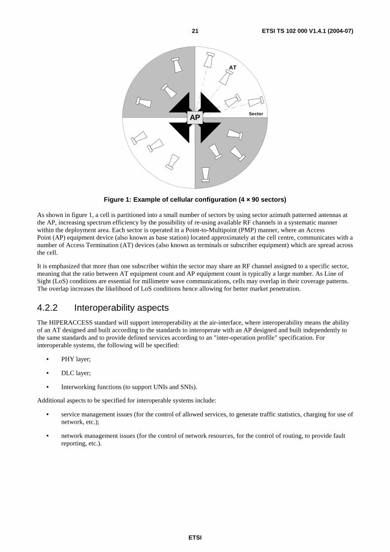
Figure 1: Example of cellular configuration (4 ×××× 90 sectors)
As shown in figure 1, a cell is partitioned into a small number of sectors by using sector azimuth patterned antennas at the AP, increasing spectrum efficiency by the possibility of re-using available RF channels in a systematic manner within the deployment area. Each sector is operated in a Point-to-Multipoint (PMP) manner, where an Access Point (AP) equipment device (also known as base station) located approximately at the cell centre, communicates with a number of Access Termination (AT) devices (also known as terminals or subscriber equipment) which are spread across the cell.
It is emphasized that more than one subscriber within the sector may share an RF channel assigned to a specific sector, meaning that the ratio between AT equipment count and AP equipment count is typically a large number. As Line of Sight (LoS) conditions are essential for millimetre wave communications, cells may overlap in their coverage patterns. The overlap increases the likelihood of LoS conditions hence allowing for better market penetration.
4.2.2 Interoperability aspects
The HIPERACCESS standard will support interoperability at the air-interface, where interoperability means the ability of an AT designed and built according to the standards to interoperate with an AP designed and built independently to the same standards and to provide defined services according to an "inter-operation profile" specification. For interoperable systems, the following will be specified:
• PHY layer;
• DLC layer;
• Interworking functions (to support UNIs and SNIs).
Additional aspects to be specified for interoperable systems include:
• service management issues (for the control of allowed services, to generate traffic statistics, charging for use of network, etc.);
• network management issues (for the control of network resources, for the control of routing, to provide fault reporting, etc.).
ETSI
ETSI TS 102 000 V1.4.1 (2004-07) 22
4.2.3 Duplex schemes (FDD, TDD) and H-FDD operation
As the communication channel between the AP and the ATs is bi-directional, the DL (downlink, direction from AP to AT) and UL (uplink, direction from AT to AP) paths shall be established utilizing the spectrum resource available to the operator. Two duplex schemes are specified, one is frequency-domain based (FDD) and one is time-domain based (TDD), used by two different operation modes of HA systems. Therefore FDD and TDD modes are optional for the AP; so one of the two modes shall be implemented. Each AT shall support the FDD mode (full or H-FDD) or the TDD mode.
• For a Frequency Division Duplex (FDD) duplex scheme, the available spectrum is partitioned into a DL RF block and an UL RF block. An RF channel is actually a pair of carriers, one from the DL RF block and one for the UL RF block, hence DL and UL transmissions are established on separate and independent radio channels. In HIPERACCESS both DL and UL carriers are equal in size and fixed to a width of 28 MHz.
• In the half-duplex FDD (H-FDD) operational mode, the AT radio equipment is limited to a half-duplex operation (i.e. transmission and reception cannot occur simultaneously), thus a relaxation of some RF design parameters is possible (e.g. isolation) and an AT cost reduction is facilitated. The DLC layer acknowledging AT limitations shall schedule the DL reception events and the UL transmission events accordingly. Furthermore the AP recognizes in this case the fact that switching from transmission operation to reception operation (and vice versa) at the AT is not immediately possible (i.e. a guard time for ramp up and down of the transmit power is required).
• It is emphasized that the H-FDD operation is an AT feature only. The AP has a different impact on the deployment cost and on system capacity (if H-FDD operation is employed at the AP). Note that in addition to the AT burst transmission capability, the H-FDD operation requires burst reception capability as well. The H-FDD operation in the AT equipment is an optional feature. However the AP equipment shall support AT equipment which has implemented this feature.
• In contrast to FDD, the Time Division Duplex (TDD) duplex scheme shall use a single carrier of 28 MHz bandwidth for DL and UL communications. The AP establishes a frame based transmission as for FDD, but additionally the frame is divided into two parts: a subframe of the frame is allocated for DL purposes and the remainder of the frame for UL purposes. This time sharing ensures that DL and UL transmission events never overlap. The ratio between the allocated time for DL transmissions and the time allocated for UL transmissions is configurable. This ratio will be identical for a given deployment region in order to maximize capacity requirements by frame synchronization of all cells.
Note that in general the TDD standard is based completely on the FDD standard. This means that the TDD operation shall use identical parameters to those of FDD, which is straightforward as the FDD operation consists of fixed length framed transmissions. In other words, FDD is the main application of HIPERACCESS systems and no specific opposed or additional optimizations for TDD are envisaged.
4.2.4 Multiplexing techniques and frame structure
As more than one AT is sharing the same UL carrier, the AP shall employ techniques controlling the access of ATs. Only TDMA (Time Division Multiple Access) shall be used. After an AT has been initialized with the system, its UL transmission events are scheduled by the AP. Scheduled events are basically time coordinates which uniquely define when the AT shall begin and end its transmission. The schedule data for UL transmission is organized in an UL map which is broadcasted in the DL. An AT can transmit in a contention based manner only for bandwidth requests.
The DL data stream to different ATs is multiplexed in the time domain (TDM). As HA systems employ adaptive PHY modes, a frame consists of a few TDM regions. Each TDM region is assigned with a specific PHY mode. Only ATs capable of receiving (i.e. successfully demodulating and decoding) the assigned PHY mode may find their DL data multiplexed in the associated TDM region. For simplifying the demodulation process, TDM regions are allocated in a robustness descending order. For example, an AT with excellent link conditions, which is assigned to a spectrum efficient PHY mode, starts its reception process at the beginning of the frame and continues through all TDM regions (using a more robust PHY mode) ending its reception process with its associated TDM region. An AT with worse link conditions will be assigned to a more robust PHY mode and its reception process will end before the AT of the previous example. Note that in any case all synchronization related operation is performed once per frame for all ATs.
The TDM region location within a frame is broadcasted at the beginning of a DL frame in the DL map, together with the UL map, used instead to give grants to different ATs. Both DL and UL maps together with the ARQ map and some other information fields are referred to as the control zone at the beginning of the frame.
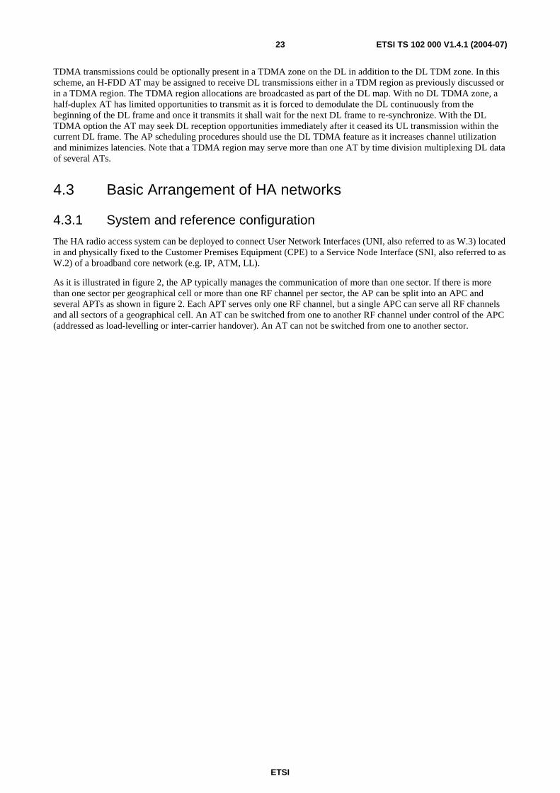
ETSI
ETSI TS 102 000 V1.4.1 (2004-07) 23
TDMA transmissions could be optionally present in a TDMA zone on the DL in addition to the DL TDM zone. In this scheme, an H-FDD AT may be assigned to receive DL transmissions either in a TDM region as previously discussed or in a TDMA region. The TDMA region allocations are broadcasted as part of the DL map. With no DL TDMA zone, a half-duplex AT has limited opportunities to transmit as it is forced to demodulate the DL continuously from the beginning of the DL frame and once it transmits it shall wait for the next DL frame to re-synchronize. With the DL TDMA option the AT may seek DL reception opportunities immediately after it ceased its UL transmission within the current DL frame. The AP scheduling procedures should use the DL TDMA feature as it increases channel utilization and minimizes latencies. Note that a TDMA region may serve more than one AT by time division multiplexing DL data of several ATs.
4.3 Basic Arrangement of HA networks
4.3.1 System and reference configuration
The HA radio access system can be deployed to connect User Network Interfaces (UNI, also referred to as W.3) located in and physically fixed to the Customer Premises Equipment (CPE) to a Service Node Interface (SNI, also referred to as W.2) of a broadband core network (e.g. IP, ATM, LL).
As it is illustrated in figure 2, the AP typically manages the communication of more than one sector. If there is more than one sector per geographical cell or more than one RF channel per sector, the AP can be split into an APC and several APTs as shown in figure 2. Each APT serves only one RF channel, but a single APC can serve all RF channels and all sectors of a geographical cell. An AT can be switched from one to another RF channel under control of the APC (addressed as load-levelling or inter-carrier handover). An AT can not be switched from one to another sector.
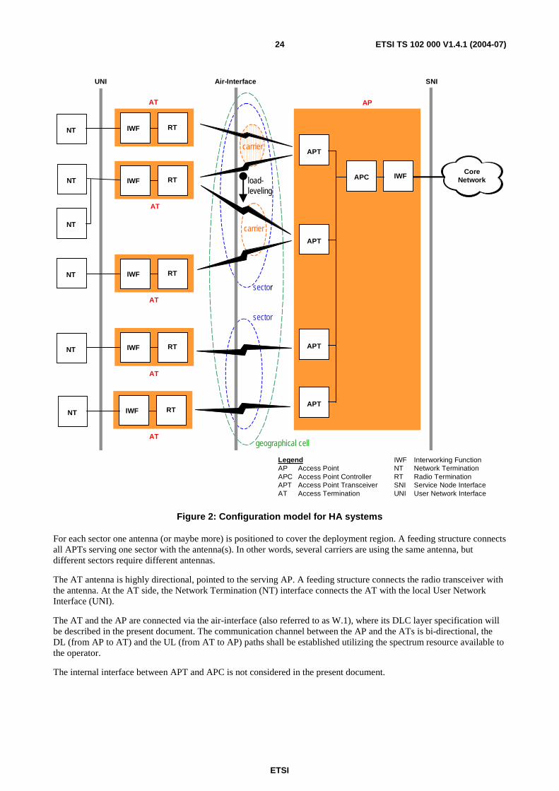
ETSI
ETSI TS 102 000 V1.4.1 (2004-07) 24
NT
NT
NT
UNI Air-Interface SNI
RTIWF
AT
AT
AT
AT
AT
APC
AP
IWF
APT
APT
APT
carrier
load-leveling
sector
sector
carrier
APT
CoreNetwork
NT
NT
NT
LegendAP Access PointAPC Access Point ControllerAPT Access Point TransceiverAT Access Termination
geographical cell
RTIWF
RTIWF
RTIWF
RTIWF
IWF Interworking FunctionNT Network TerminationRT Radio TerminationSNI Service Node InterfaceUNI User Network Interface
Figure 2: Configuration model for HA systems
For each sector one antenna (or maybe more) is positioned to cover the deployment region. A feeding structure connects all APTs serving one sector with the antenna(s). In other words, several carriers are using the same antenna, but different sectors require different antennas.
The AT antenna is highly directional, pointed to the serving AP. A feeding structure connects the radio transceiver with the antenna. At the AT side, the Network Termination (NT) interface connects the AT with the local User Network Interface (UNI).
The AT and the AP are connected via the air-interface (also referred to as W.1), where its DLC layer specification will be described in the present document. The communication channel between the AP and the ATs is bi-directional, the DL (from AP to AT) and the UL (from AT to AP) paths shall be established utilizing the spectrum resource available to the operator.
The internal interface between APT and APC is not considered in the present document.
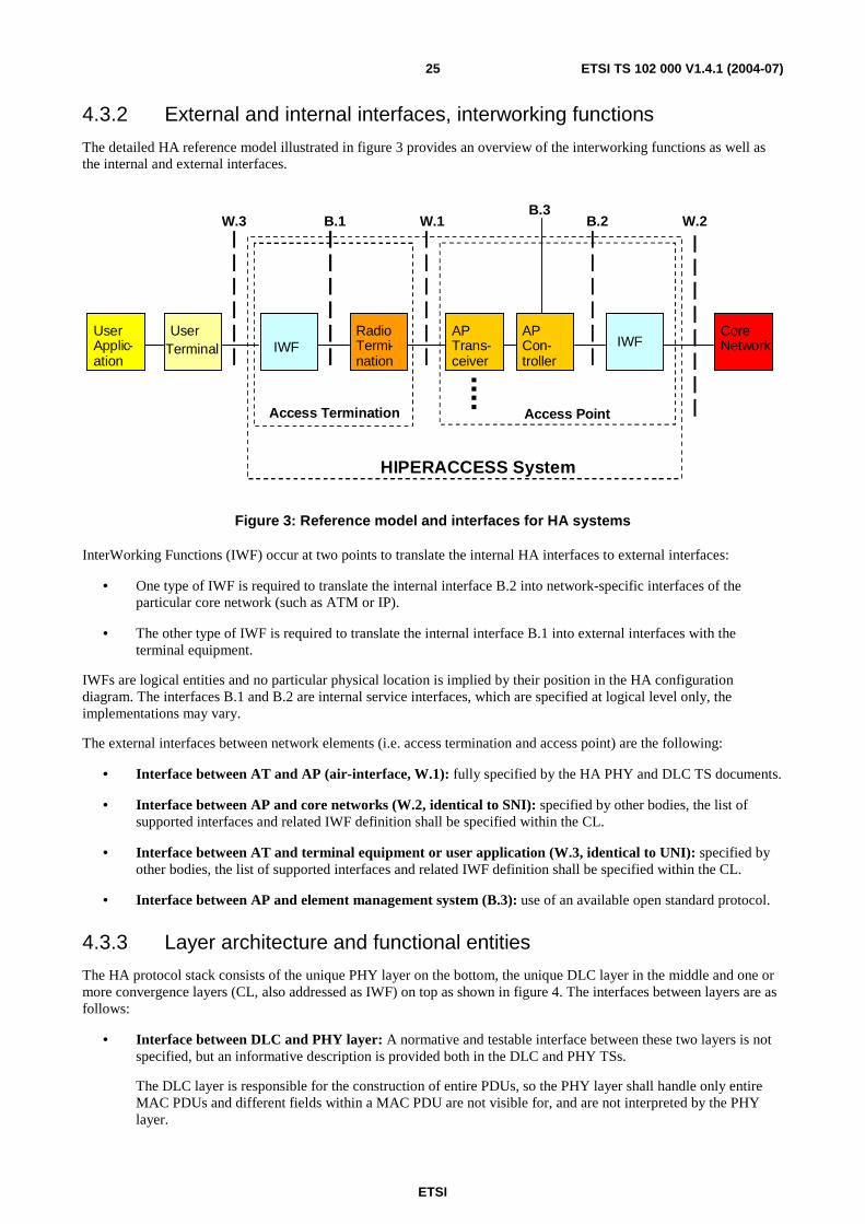
ETSI
ETSI TS 102 000 V1.4.1 (2004-07) 25
4.3.2 External and internal interfaces, interworking functions
The detailed HA reference model illustrated in figure 3 provides an overview of the interworking functions as well as the internal and external interfaces.
IWFAP Con-troller
AP Trans-ceiver
Core Network
RadioTermi-nation
IWFUserApplic-ation
W.1 B.2B.1 W.2W.3
Access Termination
HIPERACCESS System
UserTerminal
B.3
Access Point
Figure 3: Reference model and interfaces for HA systems
InterWorking Functions (IWF) occur at two points to translate the internal HA interfaces to external interfaces:
• One type of IWF is required to translate the internal interface B.2 into network-specific interfaces of the particular core network (such as ATM or IP).
• The other type of IWF is required to translate the internal interface B.1 into external interfaces with the terminal equipment.
IWFs are logical entities and no particular physical location is implied by their position in the HA configuration diagram. The interfaces B.1 and B.2 are internal service interfaces, which are specified at logical level only, the implementations may vary.
The external interfaces between network elements (i.e. access termination and access point) are the following:
• Interface between AT and AP (air-interface, W.1): fully specified by the HA PHY and DLC TS documents.
• Interface between AP and core networks (W.2, identical to SNI): specified by other bodies, the list of supported interfaces and related IWF definition shall be specified within the CL.
• Interface between AT and terminal equipment or user application (W.3, identical to UNI): specified by other bodies, the list of supported interfaces and related IWF definition shall be specified within the CL.
• Interface between AP and element management system (B.3): use of an available open standard protocol.
4.3.3 Layer architecture and functional entities
The HA protocol stack consists of the unique PHY layer on the bottom, the unique DLC layer in the middle and one or more convergence layers (CL, also addressed as IWF) on top as shown in figure 4. The interfaces between layers are as follows:
• Interface between DLC and PHY layer: A normative and testable interface between these two layers is not specified, but an informative description is provided both in the DLC and PHY TSs.
The DLC layer is responsible for the construction of entire PDUs, so the PHY layer shall handle only entire MAC PDUs and different fields within a MAC PDU are not visible for, and are not interpreted by the PHY layer.
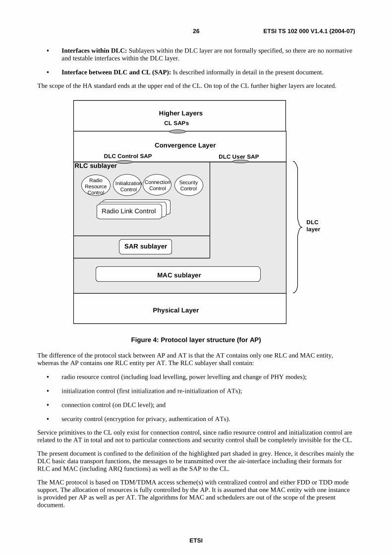
ETSI
ETSI TS 102 000 V1.4.1 (2004-07) 26
• Interfaces within DLC: Sublayers within the DLC layer are not formally specified, so there are no normative and testable interfaces within the DLC layer.
• Interface between DLC and CL (SAP): Is described informally in detail in the present document.
The scope of the HA standard ends at the upper end of the CL. On top of the CL further higher layers are located.
Physical Layer
Convergence Layer
DLC Control SAP
ConnectionControl
Radio Link Control
DLC User SAP
RLC sublayer
MAC sublayer
Higher Layers
CL SAPs
DLClayer
InitializationControl
RadioResourceControl
SecurityControl
SAR sublayer
Figure 4: Protocol layer structure (for AP)
The difference of the protocol stack between AP and AT is that the AT contains only one RLC and MAC entity, whereas the AP contains one RLC entity per AT. The RLC sublayer shall contain:
• radio resource control (including load levelling, power levelling and change of PHY modes);
• initialization control (first initialization and re-initialization of ATs);
• connection control (on DLC level); and
• security control (encryption for privacy, authentication of ATs).
Service primitives to the CL only exist for connection control, since radio resource control and initialization control are related to the AT in total and not to particular connections and security control shall be completely invisible for the CL.
The present document is confined to the definition of the highlighted part shaded in grey. Hence, it describes mainly the DLC basic data transport functions, the messages to be transmitted over the air-interface including their formats for RLC and MAC (including ARQ functions) as well as the SAP to the CL.
The MAC protocol is based on TDM/TDMA access scheme(s) with centralized control and either FDD or TDD mode support. The allocation of resources is fully controlled by the AP. It is assumed that one MAC entity with one instance is provided per AP as well as per AT. The algorithms for MAC and schedulers are out of the scope of the present document.

ETSI
ETSI TS 102 000 V1.4.1 (2004-07) 27
In order to control the allocation of resources, the AP needs to know the state of its own buffers and of the buffers in all ATs. Therefore, the ATs report their buffer states in resource request messages to the AP. Using this mechanism, the ATs request for resources in terms of transmission capacity. Moreover, an optional feature is to negotiate a fixed capacity allocation over multiple frames. The AP allocates the resources according to the buffer states on a fair basis and, if required, taking QoS parameters into account. The allocation of resources is conveyed by resource grant messages. Requests are defined on a per connection or per connection aggregate basis, whereas grants are given on a per AT basis.
The MAC sublayer includes also an instance for EC (Error Control) which is responsible for detection and recovery from transmission errors on the radio link. An ARQ (Automatic Repeat Request) protocol can be applied on a per connection basis. Most ARQ functions (like the mechanisms for requests and grants of re-transmissions) are indeed DLC related, however, the error detection itself is performed in the PHY layer. ARQ also ensures the in-sequence delivery of MAC PDUs. A dedicated ARQ instance can be assigned to each DLC connection for non-real time data services and maybe even for real time CBR services if the delay requirements are less strict. ARQ is negotiated at connection establishment. In particular ARQ shall not be applied to any RLC signalling. ARQ is only applied to the UL direction. The support and implementation of ARQ is optional for the AP but mandatory for all ATs.
NOTE: Architectures where the AP is split into an AP controller and one or more AP transceivers are not precluded by the present document. If the split between AP controller and AP transceiver is below the DLC layer, more than one MAC entity may exist in the AP controller.
4.4 Convergence Layers The function of the Convergence Layer (CL) is the Interworking Function (IWF) for mapping services over the DLC frame, specified for different services at the AT side and different core networks at the AP side. There are at least two convergence layers, a cell-based CL for ATM and a packet-based CL for IP.
The RLC sublayer receives from the CL a QoS description for each connection. The grouping of connections into connection aggregates is performed in the DLC layer.
The identifier of the Convergence Layer is called Clid and it is transported in a lot of messages. The format of the Clid is described in annex B.
4.4.1 Cell-based Convergence Layer (CL)
The cell-based Convergence Layer (CL) is dedicated to interface the ATM layer to the HA DLC layer. At ATM level several classes of service are defined together with the requirements on QoS they are able to respect. The DLC level shall be able to be compliant with the QoS requirements coming from at least the following ATM class of service:
• Constant Bit Rate (CBR);
• Variable Bit Rate real time (VBRrt);
• Variable Bit Rate non real time (VBRnrt);
• Unspecified Bit Rate (UBR).
To ensure the support of these service classes four different service categories have been defined within the DLC layer (see clause 4.4.3).
For the handling of data cells coming from the ATM layer (see clause 5.2.1).
4.4.2 Packet-based Convergence Layer
The packet-based CL (Convergence Layer) is dedicated to interface any packet oriented upper layer to the HA DLC layer. At CL a Segmentation and Reassembly (SAR) functionality shall be provided in order to exchange with the DLC level fixed packet data units.
NOTE: Another different SAR entity within the MAC sublayer is defined to segment long MAC management messages.
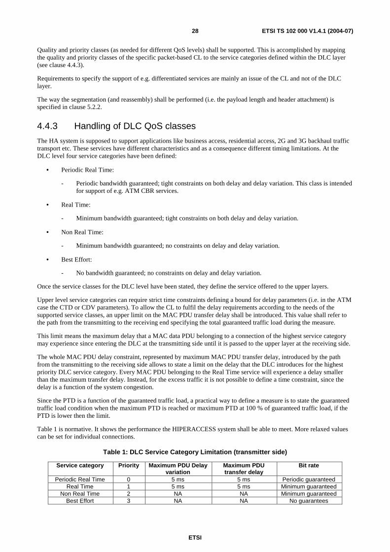
ETSI
ETSI TS 102 000 V1.4.1 (2004-07) 28
Quality and priority classes (as needed for different QoS levels) shall be supported. This is accomplished by mapping the quality and priority classes of the specific packet-based CL to the service categories defined within the DLC layer (see clause 4.4.3).
Requirements to specify the support of e.g. differentiated services are mainly an issue of the CL and not of the DLC layer.
The way the segmentation (and reassembly) shall be performed (i.e. the payload length and header attachment) is specified in clause 5.2.2.
4.4.3 Handling of DLC QoS classes
The HA system is supposed to support applications like business access, residential access, 2G and 3G backhaul traffic transport etc. These services have different characteristics and as a consequence different timing limitations. At the DLC level four service categories have been defined:
• Periodic Real Time:
- Periodic bandwidth guaranteed; tight constraints on both delay and delay variation. This class is intended for support of e.g. ATM CBR services.
• Real Time:
- Minimum bandwidth guaranteed; tight constraints on both delay and delay variation.
• Non Real Time:
- Minimum bandwidth guaranteed; no constraints on delay and delay variation.
• Best Effort:
- No bandwidth guaranteed; no constraints on delay and delay variation.
Once the service classes for the DLC level have been stated, they define the service offered to the upper layers.
Upper level service categories can require strict time constraints defining a bound for delay parameters (i.e. in the ATM case the CTD or CDV parameters). To allow the CL to fulfil the delay requirements according to the needs of the supported service classes, an upper limit on the MAC PDU transfer delay shall be introduced. This value shall refer to the path from the transmitting to the receiving end specifying the total guaranteed traffic load during the measure.
This limit means the maximum delay that a MAC data PDU belonging to a connection of the highest service category may experience since entering the DLC at the transmitting side until it is passed to the upper layer at the receiving side.
The whole MAC PDU delay constraint, represented by maximum MAC PDU transfer delay, introduced by the path from the transmitting to the receiving side allows to state a limit on the delay that the DLC introduces for the highest priority DLC service category. Every MAC PDU belonging to the Real Time service will experience a delay smaller than the maximum transfer delay. Instead, for the excess traffic it is not possible to define a time constraint, since the delay is a function of the system congestion.
Since the PTD is a function of the guaranteed traffic load, a practical way to define a measure is to state the guaranteed traffic load condition when the maximum PTD is reached or maximum PTD at 100 % of guaranteed traffic load, if the PTD is lower then the limit.
Table 1 is normative. It shows the performance the HIPERACCESS system shall be able to meet. More relaxed values can be set for individual connections.
Table 1: DLC Service Category Limitation (transmitter side)
Service category Priority Maximum PDU Delay variation
Maximum PDU transfer delay
Bit rate
Periodic Real Time 0 5 ms 5 ms Periodic guaranteed Real Time 1 5 ms 5 ms Minimum guaranteed
Non Real Time 2 NA NA Minimum guaranteed Best Effort 3 NA NA No guarantees
ETSI
ETSI TS 102 000 V1.4.1 (2004-07) 29
The delay variation reported in the table refers to the maximum peak-to-peak delay variation (PDVpeak-to-peak) that is given by the difference PTDmax - PTDmin, where PTDmin is the minimum delay experienced by a PDU in the transit through the DLC layer. If PTDmin is negligible respect to the PDTmax, the PDVpeak-to-peak and the PTDmax have the same value. In table 1 the reported delay variation is the maximum reachable value, supposing the PTDmin = 0. In case the ARQ is used the PTDmin is 3 ms at least. If PTDmin is not zero, the sum of the delay variation and the PTDmin shall be within the PTDmax. The maximum transfer delay for any single PDU shall not be larger than PTDmax.
It should be noticed that the DLC functionality, is distributed between two separated entities: for the DL the AP is the only entity involved in traffic handling, while for UL traffic decisions are taken both in AP and AT.
The AP in DL and both the AP and the AT in UL are congestion points and, due to the statistical multiplexing of traffic, they introduce a delay variation.
In the downlink direction the values of the system parameters on delay are referred to the AP only, whereas in the uplink direction, being the AT a congestion point for the incoming traffic from the line and the AP a congestion point related to the handling of the bandwidth requested by the ATs, two contributions can be defined:
• Uplink AT PTD: maximum delay introduced by the statistical multiplexing at AT level when a continuous flow of transmission grants is received from the AP.
• Uplink AP PTD: maximum delay introduced by the statistical multiplexing at AP level supposing the ATs has continuously PDUs to be transmitted.
The downlink PTD and the sum of the uplink PTDs shall be both within the maximum PTD defined as system parameter, supposing the ARQ is not used. When the ARQ is adopted, the PTD that it introduces has to be added to the uplink AT and AP PTDs and the total value shall be within the maxPTD defined as system parameter.
Since the PTD is a function of the guaranteed traffic load, a practical way to define a measure is to state the guaranteed traffic load condition when the maximum PTD is reached or the maximum PTD at 100 % of guaranteed traffic load, if the PTD is lower than the limit.
4.5 Data Link Control (DLC) Layer
4.5.1 Overview and basic features
The DLC layer is connection oriented (this means that MAC PDUs are received in the same order as sent and that a connection is set up before MAC PDUs are sent) to guarantee QoS. Connections are set up over the air during the initialization of an AT, and additionally new connections may be established when new services are required.
Both ATM and IP are supported efficiently by means of a fixed MAC PDU size of 51 bytes:
• The efficient support of ATM is achieved by a one-to-one correspondence between the ATM cells of 51 bytes (full ATM cell except HEC and VPI fields) and the MAC PDU. All mechanisms for:
- request-grant;
- ARQ (optional for AP);
- error-detection and performance monitoring;
are oriented towards MAC PDUs and thus towards ATM cells in case of cell-based CL. The solution with the shortened ATM header (of 3 bytes) offers also the unconditional support of VP switching.
• For the efficient support of IP, the variable length IP packets are mapped by SAR to the fixed size MAC PDUs.
It should be noted for cell-based CL that other solutions like selectable MAC PDU size, segmentation of ATM cells in the CL to 48 bytes or hand-shaking procedures for a (VPI,VCI) mapping to CID during connection establishments do not offer any advantages.
ARQ is not specified for the DL direction but it shall be supported by the DLC and PHY layer for the UL direction where the AP shall switch on/off ARQ on a per connection basis.
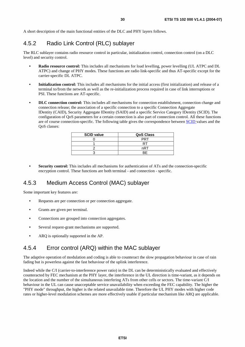
ETSI
ETSI TS 102 000 V1.4.1 (2004-07) 30
A short description of the main functional entities of the DLC and PHY layers follows.
4.5.2 Radio Link Control (RLC) sublayer
The RLC sublayer contains radio resource control in particular, initialization control, connection control (on a DLC level) and security control.
• Radio resource control: This includes all mechanisms for load levelling, power levelling (UL ATPC and DL ATPC) and change of PHY modes. These functions are radio link-specific and thus AT-specific except for the carrier-specific DL ATPC.
• Initialization control: This includes all mechanisms for the initial access (first initialization) and release of a terminal to/from the network as well as the re-initialization process required in case of link interruptions or PSI. These functions are AT-specific.
• DLC connection control: This includes all mechanisms for connection establishment, connection change and connection release; the association of a specific connection to a specific Connection Aggregate IDentity (CAID), Security Aggregate IDentity (SAID) and a specific Service Category IDentity (SCID). The configuration of QoS parameters for a certain connection is also part of connection control. All these functions are of course connection-specific. The following table gives the correspondence between SCID values and the QoS classes:
SCID value QoS Class 0 PRT 1 RT 2 nRT 3 BE
• Security control: This includes all mechanisms for authentication of ATs and the connection-specific encryption control. These functions are both terminal - and connection - specific.
4.5.3 Medium Access Control (MAC) sublayer
Some important key features are:
• Requests are per connection or per connection aggregate.
• Grants are given per terminal.
• Connections are grouped into connection aggregates.
• Several request-grant mechanisms are supported.
• ARQ is optionally supported in the AP.
4.5.4 Error control (ARQ) within the MAC sublayer
The adaptive operation of modulation and coding is able to counteract the slow propagation behaviour in case of rain fading but is powerless against the fast behaviour of the uplink interference.
Indeed while the C/I (carrier-to-interference power ratio) in the DL can be deterministically evaluated and effectively counteracted by FEC mechanism at the PHY layer, the interference in the UL direction is time-variant, as it depends on the location and the number of the simultaneous interfering ATs from other cells or sectors. The time-variant C/I behaviour in the UL can cause unacceptable service unavailability when exceeding the FEC capability. The higher the "PHY mode" throughput, the higher is the related unavailable time. Therefore the UL PHY modes with higher code rates or higher-level modulation schemes are more effectively usable if particular mechanism like ARQ are applicable.
ETSI
ETSI TS 102 000 V1.4.1 (2004-07) 31
The ARQ protocol shall be implemented at the DLC level, where the error detection is performed in the PHY layer. It is based on a selective-repeat approach as described in clause 8.5, where only the PDUs carried by erroneously received RS codewords are to be re-transmitted. In the AP, the received RS codewords are checked and in case of detected errors the RS codeword itself and all PDUs carried by this codeword are discarded. If one erroneous RS codeword in an UL frame is detected, then the AP will set an indication in the control zone of the next DL frame, enforcing a re-transmission procedure for all PDUs belonging to all erroneous RS codewords of those ATs which have at least one connection with ARQ. The impact of ARQ in terms of delay and spectrum efficiency is described in clause 8.5.5.
4.5.5 Security control within the RLC sublayer
The most important security requirements are as follows:
• Protection of traffic privacy.
• Fraud prevention.
• Checks for legitimate use.
• A "medium" security level seems enough since high-security applications will use their own end-to-end security mechanisms. As a consequence, a protection against active attacks (e.g. message integrity protection) is not provided. Furthermore, a legal interception from the air-interface is not supported, since this should be supported by the network or in higher layers.
The key mechanisms and protocols for security control are as follows:
• Authentication of ATs based on ITU-T Recommendation X.509 [9] certificates.
• Three-level cryptographic scheme:
- asymmetric RSA (Rivest Shamir Adleman), used for authentication and AK transmission;
- symmetric AK (Authentication Key), encrypted with RSA for transmission, used for TEK transmission;
- symmetric TEK (Traffic Encryption Key), encrypted with AK for transmission, used for the encryption of the payload part of all unicast traffic connections (all management connections and all broadcast connections shall not be encrypted; multicast connections shall not be encrypted for phase 1 security and phase 2 security).
• Frequent changes of AKs and TEKsare possible during traffic transmission under control of the AP.
• Security functions (authentication and encryption) can be switched off (to allow the operation of HA systems in countries where encryption is legally not allowed).
Phased security allows to operate according to phase 1 (only 4 fixed TEKs per AT, mandatory support of AP and AT) or phase 2 (frequent key updates, optional for AP and AT) or phase 3 (includes phase 2 and support of multicast encryption).
4.5.6 Multicast connections
A multicast connection is defined as follows:
• The same stream of information is addressed to a group of connections (belonging to the same or different terminals), which is referred to as a multicast group. To save bandwidth, the information is transmitted only once over the air, whereas the transmission at the SNI could be once per connection or once per multicast group. Multicast transmissions exist only in the DL. Several multicast groups comprising different sets of connections can exist in parallel. All multicast groups are dynamic, i.e. connections can be allocated to a group or withdrawn from a group at any time.
Multicast connections shall be supported. Encryption for multicast on the PHY and DLC layer is only supported in phase 3 security.
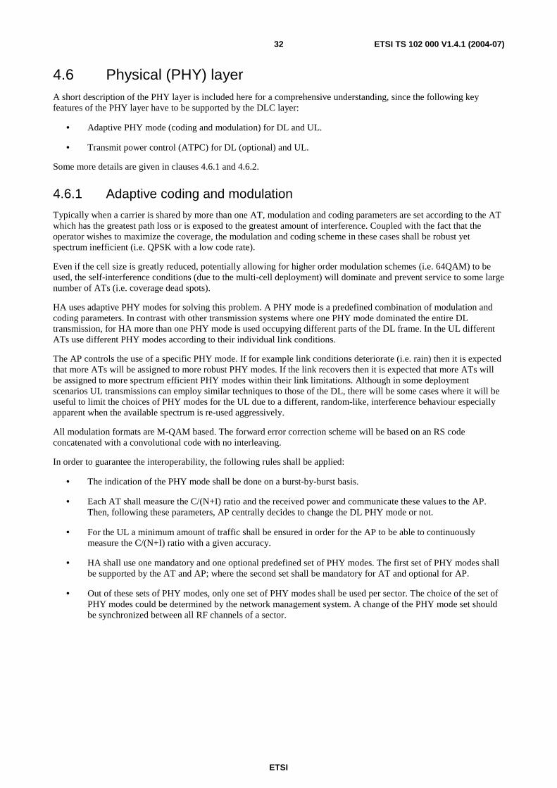
ETSI
ETSI TS 102 000 V1.4.1 (2004-07) 32
4.6 Physical (PHY) layer A short description of the PHY layer is included here for a comprehensive understanding, since the following key features of the PHY layer have to be supported by the DLC layer:
• Adaptive PHY mode (coding and modulation) for DL and UL.
• Transmit power control (ATPC) for DL (optional) and UL.
Some more details are given in clauses 4.6.1 and 4.6.2.
4.6.1 Adaptive coding and modulation
Typically when a carrier is shared by more than one AT, modulation and coding parameters are set according to the AT which has the greatest path loss or is exposed to the greatest amount of interference. Coupled with the fact that the operator wishes to maximize the coverage, the modulation and coding scheme in these cases shall be robust yet spectrum inefficient (i.e. QPSK with a low code rate).
Even if the cell size is greatly reduced, potentially allowing for higher order modulation schemes (i.e. 64QAM) to be used, the self-interference conditions (due to the multi-cell deployment) will dominate and prevent service to some large number of ATs (i.e. coverage dead spots).
HA uses adaptive PHY modes for solving this problem. A PHY mode is a predefined combination of modulation and coding parameters. In contrast with other transmission systems where one PHY mode dominated the entire DL transmission, for HA more than one PHY mode is used occupying different parts of the DL frame. In the UL different ATs use different PHY modes according to their individual link conditions.
The AP controls the use of a specific PHY mode. If for example link conditions deteriorate (i.e. rain) then it is expected that more ATs will be assigned to more robust PHY modes. If the link recovers then it is expected that more ATs will be assigned to more spectrum efficient PHY modes within their link limitations. Although in some deployment scenarios UL transmissions can employ similar techniques to those of the DL, there will be some cases where it will be useful to limit the choices of PHY modes for the UL due to a different, random-like, interference behaviour especially apparent when the available spectrum is re-used aggressively.
All modulation formats are M-QAM based. The forward error correction scheme will be based on an RS code concatenated with a convolutional code with no interleaving.
In order to guarantee the interoperability, the following rules shall be applied:
• The indication of the PHY mode shall be done on a burst-by-burst basis.
• Each AT shall measure the C/(N+I) ratio and the received power and communicate these values to the AP. Then, following these parameters, AP centrally decides to change the DL PHY mode or not.
• For the UL a minimum amount of traffic shall be ensured in order for the AP to be able to continuously measure the C/(N+I) ratio with a given accuracy.
• HA shall use one mandatory and one optional predefined set of PHY modes. The first set of PHY modes shall be supported by the AT and AP; where the second set shall be mandatory for AT and optional for AP.
• Out of these sets of PHY modes, only one set of PHY modes shall be used per sector. The choice of the set of PHY modes could be determined by the network management system. A change of the PHY mode set should be synchronized between all RF channels of a sector.

ETSI
ETSI TS 102 000 V1.4.1 (2004-07) 33
4.6.2 Automatic Transmit Power Control (ATPC)
The transmit power control is needed in order to cope with attenuation effects due to rain fading. Both UL ATPC and DL ATPC are under full control of the AP.
For the UL ATPC, each AT receives individual power adjustment commands from the AP. Usually, the UL transmit power is only changed in case of a rain fading. The AP gains the information about each AT's reasonable transmit power from the measurement of the received UL signal as well as from the parameters in the measurement reports from the ATs (where the present document contains the current transmit power and the current power margin among other parameters). As for the adaptive UL PHY mode, the AP gives enough grants to all ATs (even if the AT has no traffic to transmit) to measure the received UL power with the required precision.
In order to guarantee the interoperability, the following rules shall be applied for UL ATPC:
• The change of the transmit power shall be done on a frame-by-frame basis (both for DL and UL).
• Each AT shall report the current transmit power to the AP. Then, following these parameters and own measurements of the received UL signal, the AP decides to command an UL power adjustment.
• For the UL a minimum amount of traffic shall be ensured in order for the AP to be able to continuously measure the received UL power with a given accuracy.
In case of initial ranging, the AT shall start the transmission of the UL ranging bursts with an estimation of the proper power level. Then the power shall be increased with a pre-defined step size until the UL ranging burst is received by the AP for the first time and the AP replies with a power adjustment message. Only in case of short link interruptions, the AP can allow the AT to resume its UL transmission with the old UL transmit power setting.
The DL ATPC is an optional feature to fulfil regulatory requirements (where applicable). The DL transmit power can be changed for all carriers of a sector without notifying the ATs in advance. The DL transmit power shall be increased only if the current DL transmit power is not high enough for at least one AT in the most robust mode. In other words, the DL transmit power shall be minimized to allow the reception of the most robust PHY mode even for the AT with the worst DL radio channel conditions, but shall not be maximized to allow the use of the most efficient PHY mode for a large number of ATs.
5 Interface to PHY layer The interface between the DLC layer and the PHY layer is only informative.
Further interfaces within the DLC layer are not specified, i.e. the MAC and RLC sublayers of the DLC layer are introduced to improve the readability of the present document and are of informative character only.
5.1 Definition of MAC PDU
5.1.1 Layer overview and general definitions (CL PDU and MAC PDU)
Protocol Data Units (PDU) and Service Data Units (SDU) are only defined with respect to a specific layer. In the downward direction, the SDU is the input from an upper layer to a lower layer and the PDU is exchanged between the respective layers of transmitting and receiving entity.
To reduce the number of names and definitions, the term SDU is not widely used in the present document. For the purpose of the DLC specification, only the CL SDU and the MAC PDU are of major importance. Two overviews are provided: in figure 5 with regards to the protocol stack and in figure 6 with regards to the structure of the data fields.
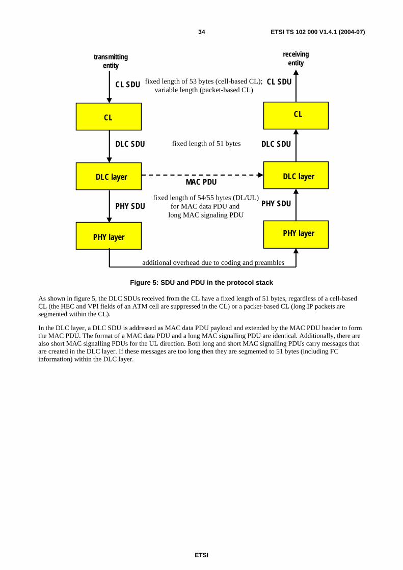
ETSI
ETSI TS 102 000 V1.4.1 (2004-07) 34
fixed length of 53 bytes (cell-based CL);variable length (packet-based CL)
transmittingentity
receivingentity
fixed length of 51 bytes
CL
DLC layer
PHY layer
fixed length of 54/55 bytes (DL/UL)for MAC data PDU and
long MAC signaling PDU
additional overhead due to coding and preambles
MAC PDU
DLC SDU
CL SDU
PHY layer
DLC layer
CL
CL SDU
DLC SDU
PHY SDU PHY SDU
Figure 5: SDU and PDU in the protocol stack
As shown in figure 5, the DLC SDUs received from the CL have a fixed length of 51 bytes, regardless of a cell-based CL (the HEC and VPI fields of an ATM cell are suppressed in the CL) or a packet-based CL (long IP packets are segmented within the CL).
In the DLC layer, a DLC SDU is addressed as MAC data PDU payload and extended by the MAC PDU header to form the MAC PDU. The format of a MAC data PDU and a long MAC signalling PDU are identical. Additionally, there are also short MAC signalling PDUs for the UL direction. Both long and short MAC signalling PDUs carry messages that are created in the DLC layer. If these messages are too long then they are segmented to 51 bytes (including FC information) within the DLC layer.
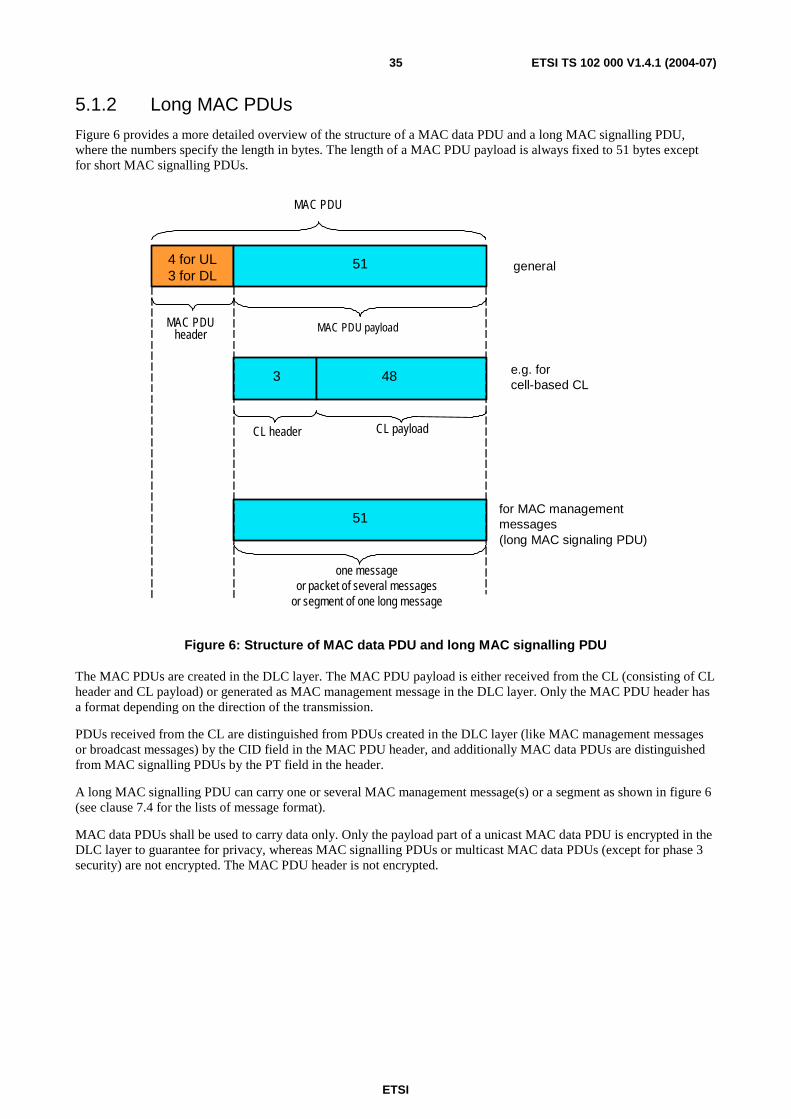
ETSI
ETSI TS 102 000 V1.4.1 (2004-07) 35
5.1.2 Long MAC PDUs
Figure 6 provides a more detailed overview of the structure of a MAC data PDU and a long MAC signalling PDU, where the numbers specify the length in bytes. The length of a MAC PDU payload is always fixed to 51 bytes except for short MAC signalling PDUs.
4 for UL3 for DL
3
51
48
general
e.g. for cell-based CL
for MAC managementmessages(long MAC signaling PDU)
MAC PDU payload
MAC PDU
MAC PDUheader
CL header CL payload
one messageor packet of several messages
or segment of one long message
51
Figure 6: Structure of MAC data PDU and long MAC signalling PDU
The MAC PDUs are created in the DLC layer. The MAC PDU payload is either received from the CL (consisting of CL header and CL payload) or generated as MAC management message in the DLC layer. Only the MAC PDU header has a format depending on the direction of the transmission.
PDUs received from the CL are distinguished from PDUs created in the DLC layer (like MAC management messages or broadcast messages) by the CID field in the MAC PDU header, and additionally MAC data PDUs are distinguished from MAC signalling PDUs by the PT field in the header.
A long MAC signalling PDU can carry one or several MAC management message(s) or a segment as shown in figure 6 (see clause 7.4 for the lists of message format).
MAC data PDUs shall be used to carry data only. Only the payload part of a unicast MAC data PDU is encrypted in the DLC layer to guarantee for privacy, whereas MAC signalling PDUs or multicast MAC data PDUs (except for phase 3 security) are not encrypted. The MAC PDU header is not encrypted.
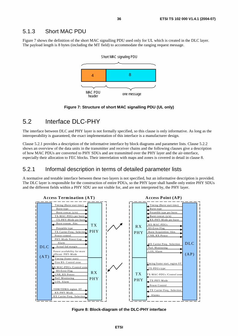
ETSI
ETSI TS 102 000 V1.4.1 (2004-07) 36
5.1.3 Short MAC PDU
Figure 7 shows the definition of the short MAC signalling PDU used only for UL which is created in the DLC layer. The payload length is 8 bytes (including the MT field) to accommodate the ranging request message.
4 8
one message
Short MAC signaling PDU
MAC PDUheader
Figure 7: Structure of short MAC signalling PDU (UL only)
5.2 Interface DLC-PHY The interface between DLC and PHY layer is not formally specified, so this clause is only informative. As long as the interoperability is guaranteed, the exact implementation of this interface is a manufacturer design.
Clause 5.2.1 provides a description of the informative interface by block diagrams and parameter lists. Clause 5.2.2 shows an overview of the data units in the transmitter and receiver chains and the following clauses give a description of how MAC PDUs are converted to PHY SDUs and are transmitted over the PHY layer and the air-interface, especially their allocation to FEC blocks. Their interrelation with maps and zones is covered in detail in clause 8.
5.2.1 Informal description in terms of detailed parameter lists
A normative and testable interface between these two layers is not specified, but an informative description is provided. The DLC layer is responsible for the construction of entire PDUs, so the PHY layer shall handle only entire PHY SDUs and the different fields within a PHY SDU are not visible for, and are not interpreted by, the PHY layer.
DLC
(AT)
D LC
(AP)
PH Y
TX
TX
RX
RX
Burst-type
TX-M AC PDU s per burst
T im ing (Burst start time)
TX-PH Y-M ode per burst
Power control
Burst concat. (y/n)
Preamble type
Burst transm . Akn.
T DM /TD M A region ST
Actual fad m argin
RX-PHY-M ode
RX M AC-PDUs /Control zone
RS-Error Flag
CNR, RX-Power
Perf. M onitoring
LOS, A larm
Tim ing (fram e start)
First RS- Control zone
TX-PH Y-M ode
Power Control
A larm s
Tim ing:frame start, region ST
TX-M AC-PDUs /Control zone
Burst-type
RX-M AC -PDU s
Tim ing (Burst start time)
RX-PHY-M ode per burst
CNR, RX-Power
Burst concat. (y/n)
Pream ble type per burst
Burst Acquisition . Akn.
RS-E rror F lag
Perf. M onitoring
PH Y
PHY
PHY
A ccess Term ination (A T) A ccess Point (A P)
PHY-M ode Power Gap
Alarm
L OS, Alarm
T X-PD Us type
TX Carrier Freq.. Selec tion
R X Carrier Freq .. Selection
RX Carrier Freq. Selection
TX Carrier Freq.. Selec tion
Power availability for m ore efficent PHY-M ode
Figure 8: Block-diagram of the DLC-PHY interface
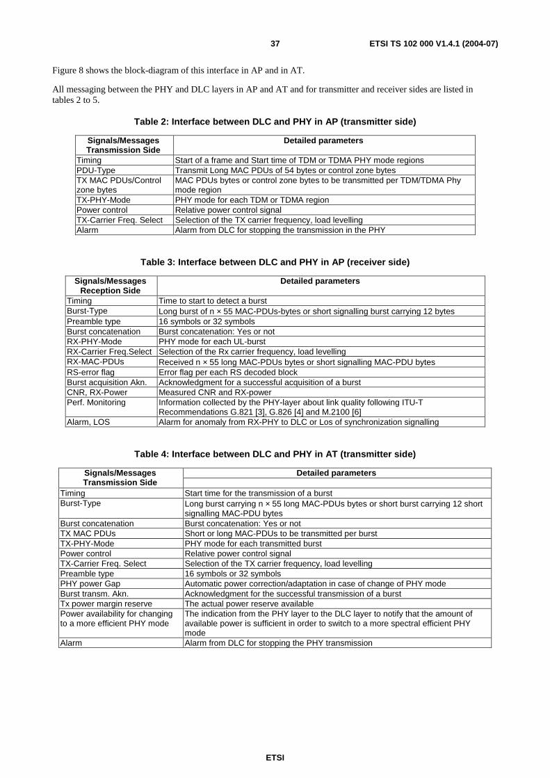
ETSI
ETSI TS 102 000 V1.4.1 (2004-07) 37
Figure 8 shows the block-diagram of this interface in AP and in AT.
All messaging between the PHY and DLC layers in AP and AT and for transmitter and receiver sides are listed in tables 2 to 5.
Table 2: Interface between DLC and PHY in AP (transmitter side)
Signals/Messages Transmission Side
Detailed parameters
Timing Start of a frame and Start time of TDM or TDMA PHY mode regions PDU-Type Transmit Long MAC PDUs of 54 bytes or control zone bytes TX MAC PDUs/Control zone bytes
MAC PDUs bytes or control zone bytes to be transmitted per TDM/TDMA Phy mode region
TX-PHY-Mode PHY mode for each TDM or TDMA region Power control Relative power control signal TX-Carrier Freq. Select Selection of the TX carrier frequency, load levelling Alarm Alarm from DLC for stopping the transmission in the PHY
Table 3: Interface between DLC and PHY in AP (receiver side)
Signals/Messages Reception Side
Detailed parameters
Timing Time to start to detect a burst Burst-Type Long burst of n × 55 MAC-PDUs-bytes or short signalling burst carrying 12 bytes Preamble type 16 symbols or 32 symbols Burst concatenation Burst concatenation: Yes or not RX-PHY-Mode PHY mode for each UL-burst RX-Carrier Freq.Select Selection of the Rx carrier frequency, load levelling RX-MAC-PDUs Received n × 55 long MAC-PDUs bytes or short signalling MAC-PDU bytes RS-error flag Error flag per each RS decoded block Burst acquisition Akn. Acknowledgment for a successful acquisition of a burst CNR, RX-Power Measured CNR and RX-power Perf. Monitoring Information collected by the PHY-layer about link quality following ITU-T
Recommendations G.821 [3], G.826 [4] and M.2100 [6] Alarm, LOS Alarm for anomaly from RX-PHY to DLC or Los of synchronization signalling
Table 4: Interface between DLC and PHY in AT (transmitter side)
Detailed parameters Signals/Messages Transmission Side
Timing Start time for the transmission of a burst Burst-Type Long burst carrying n × 55 long MAC-PDUs bytes or short burst carrying 12 short
signalling MAC-PDU bytes Burst concatenation Burst concatenation: Yes or not TX MAC PDUs Short or long MAC-PDUs to be transmitted per burst TX-PHY-Mode PHY mode for each transmitted burst Power control Relative power control signal TX-Carrier Freq. Select Selection of the TX carrier frequency, load levelling Preamble type 16 symbols or 32 symbols PHY power Gap Automatic power correction/adaptation in case of change of PHY mode Burst transm. Akn. Acknowledgment for the successful transmission of a burst Tx power margin reserve The actual power reserve available Power availability for changing to a more efficient PHY mode
The indication from the PHY layer to the DLC layer to notify that the amount of available power is sufficient in order to switch to a more spectral efficient PHY mode
Alarm Alarm from DLC for stopping the PHY transmission

ETSI
ETSI TS 102 000 V1.4.1 (2004-07) 38
Table 5: Interface between DLC and PHY in AT (receiver side)
Signals/Messages Reception Side
Detailed parameters
Timing Detection of the beginning of a frame: Frame start time First RS-Control zone First 30 bytes of control zone RX MAC-PDUs/Control zone bytes
Received n × long MAC-PDUs of 55 bytes or control zone bytes
RS-error flag Error flag per each RS decoded block CNR, RX-Power Measured CNR and RX-power Perf. Monitoring Information collected by the PHY-layer about link quality following ITU-T
Recommendations G.821 [3], G.826 [4] and M.2100 [6] Alarm, LOS Alarm for anomaly from RX-PHY to DLC or Los of synchronization signalling TDM/TDMA region ST Start time for detecting each TDM or TDMA PHY mode region RX-PHY-Mode PHY mode for each DL TDM or TDMA PHY mode region RX-Carrier Freq.Select Selection of the Rx carrier frequency, load levelling
Some additional remarks:
NOTE 1: PHY functions include (for transmitter): insertion of zero bits for trellis termination; insertion of padding bits to complete a modulation symbol; insertion of padding channel symbols to complete the fixed frame duration; creation and insertion of preambles; scrambling; timing for frame and burst duration; maintaining of time synchronization.
NOTE 2: DLC functions include (for transmitter): creation of MAC PDUs or PHY SDUs; creation of control zone (including frame number); organization of re-transmissions for ARQ and creation of ARQ entries; creation of MAC dummy PDUs; creation of ranging request messages (for AT only); maintaining of minimum data rate in UL; segmentation of MAC management messages; encryption and decryption of MAC PDU payload.
The frame structure with a fixed duration of 1 ms is both relevant for DLC and PHY layers.
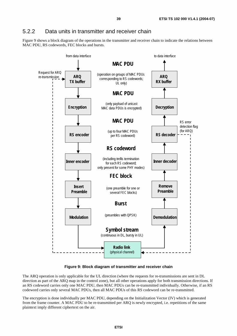
ETSI
ETSI TS 102 000 V1.4.1 (2004-07) 39
5.2.2 Data units in transmitter and receiver chain
Figure 9 shows a block diagram of the operations in the transmitter and receiver chain to indicate the relations between MAC PDU, RS codewords, FEC blocks and bursts.
Radio link (physical channel)
RS encoder
Inner encoder
Insert Preamble
Modulation Demodulation
RemovePreamble
Inner decoder
RS decoder
Encryption Decryption
ARQTX buffer
MAC PDU
MAC PDU
MAC PDU
RS codeword
FEC block
Burst
Symbol stream(continuous in DL, bursty in UL)
(preambles with QPSK)
(one preamble for one or several FEC blocks)
(including trellis terminationfor each RS codeword;
only present for some PHY modes)
(up to four MAC PDUsper RS codeword)
(only payload of unicastMAC data PDUs is encrypted)
(operation on groups of MAC PDUs corresponding to RS codewords;
UL only)
ARQRX buffer
from data interface to data interface
RS errordetection flag(for ARQ)
Request for ARQre-transmission
Figure 9: Block diagram of transmitter and receiver chain
The ARQ operation is only applicable for the UL direction (where the requests for re-transmissions are sent in DL direction as part of the ARQ map in the control zone), but all other operations apply for both transmission directions. If an RS codeword carries only one MAC PDU, then MAC PDUs can be re-transmitted individually. Otherwise, if an RS codeword carries only several MAC PDUs, then all MAC PDUs of this RS codeword can be re-transmitted.
The encryption is done individually per MAC PDU, depending on the Initialization Vector (IV) which is generated from the frame counter. A MAC PDU to be re-transmitted per ARQ is newly encrypted, i.e. repetitions of the same plaintext imply different ciphertext on the air.
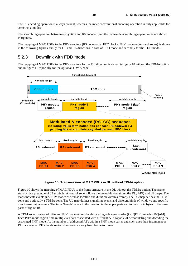
ETSI
ETSI TS 102 000 V1.4.1 (2004-07) 40
The RS encoding operation is always present, whereas the inner convolutional encoding operation is only applicable for some PHY modes.
The scrambling operation between encryption and RS encoder (and the inverse de-scrambling) operation is not shown in figure 9.
The mapping of MAC PDUs to the PHY structure (RS codewords, FEC blocks, PHY mode regions and zones) is shown in the following figures, firstly for DL and UL directions in case of FDD mode and secondly for the TDD mode.
5.2.3 Downlink with FDD mode
The mapping of MAC PDUs to the PHY structure for the DL direction is shown in figure 10 without the TDMA option and in figure 11 especially for the optional TDMA zone.
Control zone TDM zone
1 ms (fixed duration)
variable length
PHY mode 1region
PHY mode 2region
PHY mode 4 (last)region
variable length variable length variable length
FramePadding
Modulated & encoded (RS+CC) sequenceincluding trellis termination bits per each RS codeword &
padding bits to complete a symbol per each FEC block
Preamble(32 symbols)
RS codeword RS codeword RS codewordLast
RS codeword
fixed length fixed length fixed length variable length
MACPDU 1
MACPDU 2
MACPDU 3
MACPDU 4
MACPDU 1
MACPDU 2
MACPDU N
where N=1,2,3,4
Figure 10: Transmission of MAC PDUs in DL without TDMA option
Figure 10 shows the mapping of MAC PDUs to the frame structure in the DL without the TDMA option. The frame starts with a preamble of 32 symbols. A control zone follows the preamble containing the DL, ARQ and UL maps. The maps indicate events (i.e. PHY modes as well as location and duration within a frame). The DL map defines the TDM zone and optionally a TDMA zone. The UL map defines signalling events and different kinds of windows and specific user transmission events. The term "length" refers to the duration in the upper parts and to the size in bytes in the lower parts of figure 10.
A TDM zone consists of different PHY mode regions by descending robustness order (i.e. QPSK precedes 16QAM). Each PHY mode region time multiplexes data associated with different ATs capable of demodulating and decoding the associated PHY mode. As the number of addressed ATs within a PHY mode varies and such does their instantaneous DL data rate, all PHY mode region durations can vary from frame to frame.
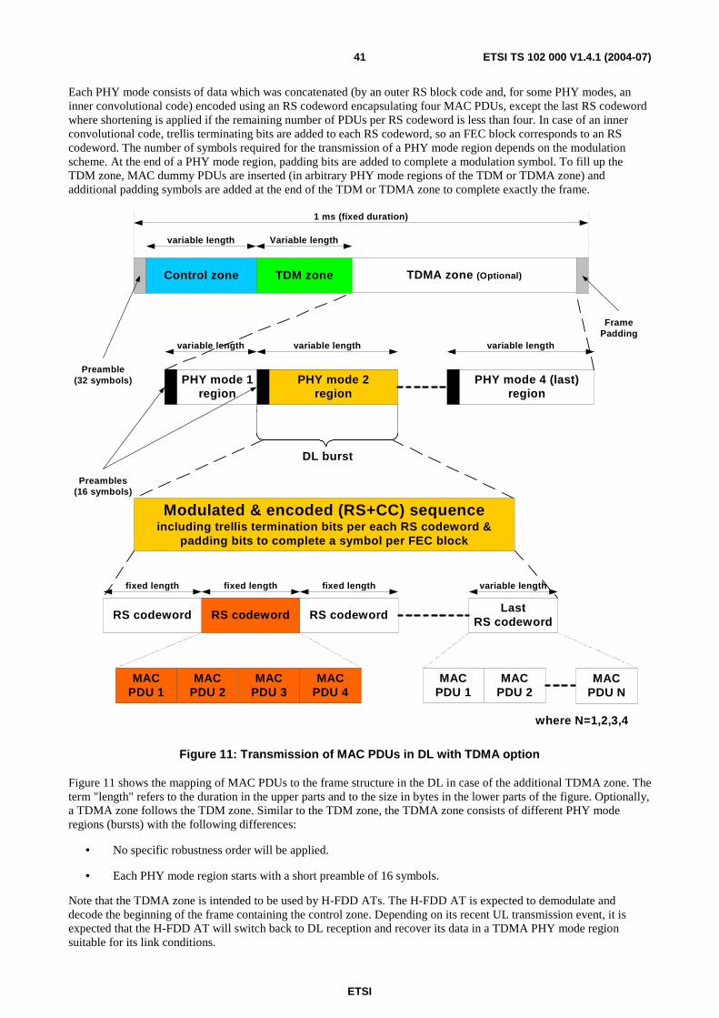
ETSI
ETSI TS 102 000 V1.4.1 (2004-07) 41
Each PHY mode consists of data which was concatenated (by an outer RS block code and, for some PHY modes, an inner convolutional code) encoded using an RS codeword encapsulating four MAC PDUs, except the last RS codeword where shortening is applied if the remaining number of PDUs per RS codeword is less than four. In case of an inner convolutional code, trellis terminating bits are added to each RS codeword, so an FEC block corresponds to an RS codeword. The number of symbols required for the transmission of a PHY mode region depends on the modulation scheme. At the end of a PHY mode region, padding bits are added to complete a modulation symbol. To fill up the TDM zone, MAC dummy PDUs are inserted (in arbitrary PHY mode regions of the TDM or TDMA zone) and additional padding symbols are added at the end of the TDM or TDMA zone to complete exactly the frame.
Preamble(32 symbols)
Preambles(16 symbols)
Modulated & encoded (RS+CC) sequenceincluding trellis termination bits per each RS codeword &
padding bits to complete a symbol per FEC block
RS codeword RS codeword RS codewordLast
RS codeword
fixed length fixed length fixed length variable length
MACPDU 1
MACPDU 2
MACPDU 3
MACPDU 4
MACPDU 1
MACPDU 2
MACPDU N
PHY mode 1region
PHY mode 2region
PHY mode 4 (last)region
FramePadding
Control zone TDM zone
1 ms (fixed duration)
variable length Variable length
variable length variable length variable length
TDMA zone (Optional)
DL burst
where N=1,2,3,4
Figure 11: Transmission of MAC PDUs in DL with TDMA option
Figure 11 shows the mapping of MAC PDUs to the frame structure in the DL in case of the additional TDMA zone. The term "length" refers to the duration in the upper parts and to the size in bytes in the lower parts of the figure. Optionally, a TDMA zone follows the TDM zone. Similar to the TDM zone, the TDMA zone consists of different PHY mode regions (bursts) with the following differences:
• No specific robustness order will be applied.
• Each PHY mode region starts with a short preamble of 16 symbols.
Note that the TDMA zone is intended to be used by H-FDD ATs. The H-FDD AT is expected to demodulate and decode the beginning of the frame containing the control zone. Depending on its recent UL transmission event, it is expected that the H-FDD AT will switch back to DL reception and recover its data in a TDMA PHY mode region suitable for its link conditions.

ETSI
ETSI TS 102 000 V1.4.1 (2004-07) 42
The PHY mode region shall be composed of one or more FEC blocks. Every FEC block shall contain 4 MAC PDUs, only the last FEC block in a PHY burst shall contain a number of MAC PDUs equal to 1, 2, 3 or 4 in order to complete the transmission of the number of MAC PDUs foreseen for the burst. The number of symbols within each FEC block depends on the relevant PHY mode. The total length of a burst shall be an integer number of symbols, the last symbol shall be padded with bit values equal to 0 as necessary.
5.2.4 Uplink with FDD mode
The UL frame is subdivided in:
• A window or windows for contention-based access (i.e. non-scheduled transmissions) where only bandwidth requests are allowed. Only short MAC signalling PDUs with the most robust PHY mode shall be transmitted in contention windows.
• Scheduled bursts (i.e. granted bursts for invited traffic from AT), applies for:
- MAC data PDUs;
- long MAC signalling PDUs;
- short MAC signalling PDUs;
- ranging bursts (always with the most robust PHY mode);
where each PHY mode can be scheduled for the first three cases).
The locations of these different parts within an UL frame are indicated by the UIUC entries in the UL map which is broadcasted in the control zone in the DL at the beginning of each frame. See clause 8.2.2 for more details on the UL frame structure.
An UL burst for an AT transmission may include more than one MAC PDU or more than one FEC block similar to the DL direction. MAC PDUs shall be encapsulated into RS codewords of fixed length. The last RS codeword will be shortened in the case where the number of remaining MAC PDUs is less than four. As the AT finishes to transmit its UL burst, it may ramp-down its transmitter. This period of time is expected to overlap a ramp-up period of the next AT UL burst scheduled for transmission.
An UL burst can either contain a mixture of MAC data PDUs and long MAC signalling PDUs (and maybe dummy PDUs if nothing else is to be transmitted) or one short MAC signalling PDU. In other words, an UL burst with one short MAC signalling PDU can not contain a further short MAC signalling PDU or a long MAC PDU.
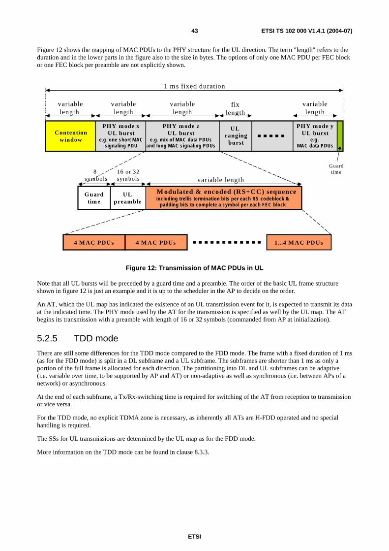
ETSI
ETSI TS 102 000 V1.4.1 (2004-07) 43
Figure 12 shows the mapping of MAC PDUs to the PHY structure for the UL direction. The term "length" refers to the duration and in the lower parts in the figure also to the size in bytes. The options of only one MAC PDU per FEC block or one FEC block per preamble are not explicitly shown.
1 m s fixed duration
Guardtime
PHY mode xUL burst
e.g. one short M ACsignaling PDU
variablelength
variablelength
Contentionwindow
PHY mode yUL burst
e.g. MAC data PDUs
4 M AC PDUs 1...4 M AC PD Us4 M AC PDUs
variablelength
variablelength
M odulated & encoded (RS+CC) sequenceincluding trellis term ination bits per each RS codeblock &
padding bits to com plete a sym bol per each FEC block
ULpreamble
8 symbols
Guardtime
16 or 32 symbols variable length
PHY mode zUL burst
e.g. m ix of M AC data PDU sand long MAC signaling PDUs
UL ranging
burst
fixlength
Figure 12: Transmission of MAC PDUs in UL
Note that all UL bursts will be preceded by a guard time and a preamble. The order of the basic UL frame structure shown in figure 12 is just an example and it is up to the scheduler in the AP to decide on the order.
An AT, which the UL map has indicated the existence of an UL transmission event for it, is expected to transmit its data at the indicated time. The PHY mode used by the AT for the transmission is specified as well by the UL map. The AT begins its transmission with a preamble with length of 16 or 32 symbols (commanded from AP at initialization).
5.2.5 TDD mode
There are still some differences for the TDD mode compared to the FDD mode. The frame with a fixed duration of 1 ms (as for the FDD mode) is split in a DL subframe and a UL subframe. The subframes are shorter than 1 ms as only a portion of the full frame is allocated for each direction. The partitioning into DL and UL subframes can be adaptive (i.e. variable over time, to be supported by AP and AT) or non-adaptive as well as synchronous (i.e. between APs of a network) or asynchronous.
At the end of each subframe, a Tx/Rx-switching time is required for switching of the AT from reception to transmission or vice versa.
For the TDD mode, no explicit TDMA zone is necessary, as inherently all ATs are H-FDD operated and no special handling is required.
The SSs for UL transmissions are determined by the UL map as for the FDD mode.
More information on the TDD mode can be found in clause 8.3.3.
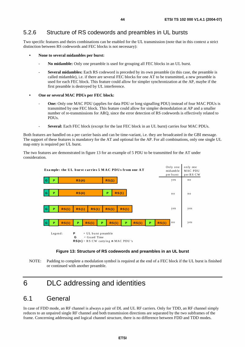
ETSI
ETSI TS 102 000 V1.4.1 (2004-07) 44
5.2.6 Structure of RS codewords and preambles in UL bursts
Two specific features and theirs combinations can be enabled for the UL transmission (note that in this context a strict distinction between RS codewords and FEC blocks is not necessary):
• None to several midambles per burst:
- No midamble: Only one preamble is used for grouping all FEC blocks in an UL burst.
- Several midambles: Each RS codeword is preceded by its own preamble (in this case, the preamble is called midamble), i.e. if there are several FEC blocks for one AT to be transmitted, a new preamble is used for each FEC block. This feature could allow for simpler synchronization at the AP, maybe if the first preamble is destroyed by UL interference.
• One or several MAC PDUs per FEC block:
- One: Only one MAC PDU (applies for data PDU or long signalling PDU) instead of four MAC PDUs is transmitted by one FEC block. This feature could allow for simpler demodulation at AP and a smaller number of re-transmissions for ARQ, since the error detection of RS codewords is effectively related to PDUs.
- Several: Each FEC block (except for the last FEC block in an UL burst) carries four MAC PDUs.
Both features are handled on a per carrier basis and can be time-variant, i.e. they are broadcasted in the GBI message. The support of these features is mandatory for the AT and optional for the AP. For all combinations, only one single UL map entry is required per UL burst.
The two features are demonstrated in figure 13 for an example of 5 PDU to be transmitted for the AT under consideration.
y es n o
n o n o
y es y es
n o y es
Leg en d : P = UL b u rst p reamb leG = Gu ard Time
RS (n ) = R S C W carry in g n MAC PDU ‘s
On ly o n e mid amb lep er b u rs t
RS (4)
P RS (4)
RS (1)
G PP
G
P
G P
RS (1)
RS (1)
RS (1) RS (1) RS (1) RS (1)
RS (1)G P RS (1)RS (1) RS (1)RS (1) PP P P
Exa mple : the U L b ur st c ar r ie s 5 M A C PD U s fr om one A To n ly on e MAC PDUp er R S C W
Figure 13: Structure of RS codewords and preambles in an UL burst
NOTE: Padding to complete a modulation symbol is required at the end of a FEC block if the UL burst is finished or continued with another preamble.
6 DLC addressing and identities
6.1 General In case of FDD mode, an RF channel is always a pair of DL and UL RF carriers. Only for TDD, an RF channel simply reduces to an unpaired single RF channel and both transmission directions are separated by the two subframes of the frame. Concerning addressing and logical channel structure, there is no difference between FDD and TDD modes.

ETSI
ETSI TS 102 000 V1.4.1 (2004-07) 45
The main identities to be handled in a HA system are as follows:
• The APC-ID (24 bits) is used to identify the sector during initialization.
• The AT MAC address (based on MAC-48, 48 bits) is used to identify the AT during initialization and authentication.
• The terminal identity (TID, 10 bits) is used in the control zone for the UL map for the allocation of grants to the ATs, in the multiple-TID message.
• The connection identity (CID, 16 bits) is used in the MAC PDU header for DL and UL to identify the connection. Some specific CIDs are used to identify MAC management connections and are thus AT-specific.
• The connection aggregate identity (CAID, 16 bits) is used in the bandwidth request message and the queue status request message.
• The security associate identity (SAID, 16 bits) is used in security and connection control messages and is specified in clause 12.
6.2 APC Identity (APC-ID) The APC-ID (APC Identity) is used to identify the access point controller and so the cell site. The scope is to facilitate and speed up the initialization process by identifying the cell site.
The APC-ID consists of 24 bits. The first 4 bits are used to distinguish between different operators (operator colour code) and the remaining 20 bits are used to identify the APC.
The APC-ID is transmitted in each control zone, i.e. with a period of 1 ms.
6.3 Access Terminal (AT) Identities A long world-wide unique terminal identity of 48 bits related to the terminal equipment (AT MAC address) and a short sector-wide unique terminal identity (TID) of 10 bits have to be distinguished.
6.3.1 AT MAC address (equipment ID based on MAC-48)
A permanent world-wide unique AT MAC address of 48 bits length is used for terminal identification during the first initialization or re-initialization, especially for the initial ranging message and for authentication.
The AT MAC address is based on MAC-48 (see IEEE 802 in bibliography) and related to the terminal equipment. Hence, this is not a logical identity, in case of equipment replacement (e.g. due to an equipment failure) the AT MAC address will change.
6.3.2 Terminal Identity (TID)
The terminal identity (TID) of 10 bit is used in the control zone for the UL map entries for the allocation of grants to the ATs and also in multiple-TID messages. The TID is unique per carrier. Up to 1 024 ATs per carrier are supported with regards to addressing. However, due to the noise floor limitation, the number of ATs per sector is limited to 254 and the number of ATs per carrier is also limited to 254.
According to annex B, some specific TIDs shall be used for:
• UL map entries that indicate bandwidth request contention windows.
• End of map entries.
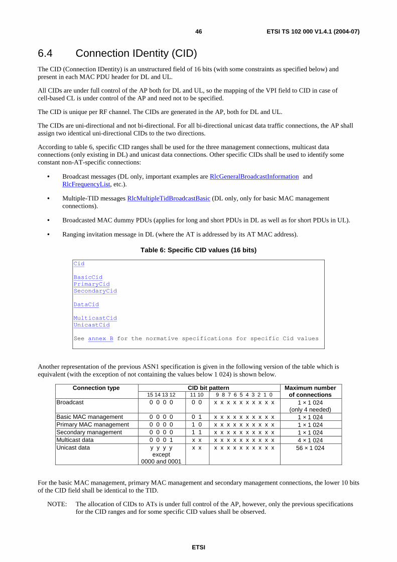
ETSI
ETSI TS 102 000 V1.4.1 (2004-07) 46
6.4 Connection IDentity (CID) The CID (Connection IDentity) is an unstructured field of 16 bits (with some constraints as specified below) and present in each MAC PDU header for DL and UL.
All CIDs are under full control of the AP both for DL and UL, so the mapping of the VPI field to CID in case of cell-based CL is under control of the AP and need not to be specified.
The CID is unique per RF channel. The CIDs are generated in the AP, both for DL and UL.
The CIDs are uni-directional and not bi-directional. For all bi-directional unicast data traffic connections, the AP shall assign two identical uni-directional CIDs to the two directions.
According to table 6, specific CID ranges shall be used for the three management connections, multicast data connections (only existing in DL) and unicast data connections. Other specific CIDs shall be used to identify some constant non-AT-specific connections:
• Broadcast messages (DL only, important examples are RlcGeneralBroadcastInformation and RlcFrequencyList, etc.).
• Multiple-TID messages RlcMultipleTidBroadcastBasic (DL only, only for basic MAC management connections).
• Broadcasted MAC dummy PDUs (applies for long and short PDUs in DL as well as for short PDUs in UL).
• Ranging invitation message in DL (where the AT is addressed by its AT MAC address).
Table 6: Specific CID values (16 bits)
Cid BasicCid PrimaryCid SecondaryCid DataCid MulticastCid UnicastCid See annex B for the normative specifications for specific Cid values
Another representation of the previous ASN1 specification is given in the following version of the table which is equivalent (with the exception of not containing the values below 1 024) is shown below.
CID bit pattern Connection type 15 14 13 12 11 10 9 8 7 6 5 4 3 2 1 0
Maximum number of connections
Broadcast 0 0 0 0 0 0 x x x x x x x x x x 1 × 1 024 (only 4 needed)
Basic MAC management 0 0 0 0 0 1 x x x x x x x x x x 1 × 1 024 Primary MAC management 0 0 0 0 1 0 x x x x x x x x x x 1 × 1 024 Secondary management 0 0 0 0 1 1 x x x x x x x x x x 1 × 1 024 Multicast data 0 0 0 1 x x x x x x x x x x x x 4 × 1 024 Unicast data y y y y
except 0000 and 0001
x x x x x x x x x x x x 56 × 1 024
For the basic MAC management, primary MAC management and secondary management connections, the lower 10 bits of the CID field shall be identical to the TID.
NOTE: The allocation of CIDs to ATs is under full control of the AP, however, only the previous specifications for the CID ranges and for some specific CID values shall be observed.
ETSI
ETSI TS 102 000 V1.4.1 (2004-07) 47
6.5 Connection Aggregate Identity (CAID) The grouping of connections to connection aggregates shall be under full control of the AP and the result of the grouping is communicated to the AT during connection establishment. Later re-groupings are possible.
Connections belonging to different QoS classes should not be grouped into the same connection aggregate (to allow vendor-specific QoS implementations).
A specific identity for a connection aggregate does exist with 16 bits. For requests, connection aggregates in total are addressed by an arbitrary CID inside the connection aggregate, i.e. the CAID is not used for requests per grant management field in the MAC PDU header. However, the CAID is used in the payload of the queue status request message and the bandwidth request message.
In order to request bandwidth especially for MAC management messages by using the bandwidth request message RlcBandwidthReq or the queue status request message RlcQueueStatusReq (where both messages contain only references to connection aggregates), specific CAID values (which can be selected arbitrarily at AP) are provided to the AT during the ranging procedure with the RlcRangingInvitation message. See annex B for the CAID specification.
7 MAC management messages: mapping to MAC management connections, transport and list of all messages
Transport and logical channels are not formally introduced in the present document.
7.1 Overview of connection types Three management connections are established for both directions at AT initialization with AT-specific CIDs:
• Basic MAC management connection is used to transport shorter, more delay-intolerant (urgent) MAC management messages such as ranging requests, signalling for adaptive operation and power control and for connection management, etc.
• Primary MAC management connection is used to exchange longer, more delay-tolerant MAC management messages such as key management, etc.
• Secondary management connection is set up to transfer delay-tolerant standards based information such as DHCP, SNMP, TFTP, etc.
The basic and primary MAC management connections are dedicated for the communication between the DLC protocol entities. The secondary management connection is dedicated for the communication between upper layers.
In addition to these AT-specific management connections, certain MAC management messages can also be transmitted per broadcast:
• Broadcast connection exists only for DL and is characterized by the broadcast CID. It shall be used with the most robust PHY mode (even if all current initialized ATs are able to decode high-level modulation, to guarantee the reception of the broadcast channel for new ATs during initialization).
• An important particular message for the broadcast connection is the GBI message:
- RlcGeneralBroadcastInformation carrying general information relevant to all ATs and especially the description of the current PHY mode set (and new PHY mode set, if applicable).
ETSI
ETSI TS 102 000 V1.4.1 (2004-07) 48
Another type of broadcast connection is:
• Multiple-TID message:
- RlcMultipleTidBroadcastBasic (with the CID MultipleTidBroadcastBasicCid), addressing several ATs. The payload of these messages is a packet of pairs (TID, one message for the respective AT), where only basic MAC management messages are carried. The specification of the multiple-TID messages is given in annex B and also illustrated in figure 14.
Furthermore, several:
• Multicast connections can be set up for specific groups of ATs to transport multicast MAC data PDUs. The multicast CIDs have the same generic format as all other CIDs.
Broadcast information can be transmitted in the broadcast connection (e.g. GBI message or other MAC management messages) or in the control zone. The control zone appears at the beginning of each frame ("fast channel"), whereas the GBI message is usually transmitted in long intervals only ("slow connection").
All MAC management messages transmitted in the three MAC management connections or in the broadcast connection are carried with the same generic MAC PDU format (MAC signalling PDU) as used for the regular traffic (MAC data PDU).
The basic MAC management, primary MAC management and secondary management connections are of unicast type and can be transmitted with any PHY mode in DL or UL. The broadcast connection (but not the multicast connections) shall be transmitted always with the most robust PHY mode in the DL to guarantee their reception by all ATs.
7.2 Transport of MAC management messages with MAC Signalling PDUs
Long (both DL and UL) as well as short (UL only) MAC signalling PDUs are specified, see clause 8.1 for the exact formats. These MAC signalling PDUs and the MAC data PDUs (and additionally MAC dummy PDUs) are identified by the PT field in the generic MAC PDU header.
7.2.1 Some general rules
Some general rules for the use of MAC signalling PDUs are summarized below.
• Opportunities for transmitting with both long and short MAC signalling PDUs in the UL can be granted to the AT. It should be noted that grants for MAC data PDUs and long MAC signalling PDUs can not be distinguished in the UL map.
• The AT can issue requests for bandwidth (both MAC data PDUs and long MAC signalling PDUs). Specific requests for short MAC signalling PDUs are also possible via the RSB bit in the MAC PDU header.
• The AT can use granted bandwidth for sending a MAC management message, but this shall be in the form of a long MAC signalling PDU (instead of a MAC data PDU) or short MAC signalling PDU. Specific rules for using granted short MAC signalling PDUs are summarized in clause 7.2.3.
• In bandwidth contention windows only short MAC signalling PDUs are allowed with PHY mode #1 carrying the message for bandwidth requests. However, the bandwidth request message can also be sent in granted short UL bursts.
• Short MAC signalling PDUs shall be used for granted short bursts and for bandwidth contention windows as well as for granted ranging bursts (during first initialization or re-initialization).
• It is possible to combine several messages into one long MAC signalling PDU for the same AT (applies for DL) or from the same AT (applies for UL) by packing. The short MAC signalling PDU (UL only) contains always only one or no message (to avoid problems with packing).
• It is possible to combine messages for several ATs (applies only for DL) into one MAC signalling PDU as RlcMultipleTidBroadcastBasic message.
ETSI
ETSI TS 102 000 V1.4.1 (2004-07) 49
• Segmentation of MAC management messages is possible for DL and UL directions, but not in combination with packing or multiple-TID message.
• An UL burst contains either one or several long MAC PDUs (can be a mixture of long MAC signalling PDUs and MAC data PDUs and MAC dummy PDUs, can consist of several FEC blocks) or exactly one short MAC signalling PDU (a specific UL ranging burst with extra guard time is specified for short MAC signalling PDUs carrying ranging requests). A mixture of short and long MAC PDUs or several short MAC signalling PDUs in one UL burst shall not be supported.
• If the AT receives grants for transmission without having any data (traffic or signalling) to transmit, then it shall send long or short MAC dummy PDUs (as specified by the grant).
• It is up to the schedulers in the AP (giving grants for UL) and the AT (using grants for UL) to determine how MAC management messages shall be transmitted, e.g. with long or short MAC signalling PDUs (if applicable). Hence there is no pre-defined binding between MAC management messages and MAC signalling PDUs in the UL (with some exceptions, see clause 7.2.3).
• Padding shall be used to fill up any unfilled payload part of any MAC signalling PDU.
7.2.2 The use of long MAC signalling PDUs
The long MAC signalling PDUs are created in the DLC layer.
Short (i.e. compared to 51 bytes) MAC management messages shall have the option to be packed and transmitted in one long MAC signalling PDU as specified in clause 7.3. This applies both for DL (for the same AT) and UL (from the same AT). Additionally, several short messages for different ATs can be packed together in one multiple-TID message. All messages that are allowed to be packed are listed in clause 7.4.
Long (i.e. longer than 51 bytes) MAC management messages shall be segmented (SAR, segmentation and reassembly, part of the MAC sublayer) as specified in clause 7.3. Examples for very long MAC management messages are asymmetric keys and the AT certificate.
Two types of long MAC signalling PDUs are distinguished by the PT field in the header:
• Non-segmented long MAC signalling PDU carries one MAC management message or a packet of several MAC management messages, if the total length is smaller than or equal to 51 bytes (after encoding).
• Segmented long MAC signalling PDU carries segments of long MAC management messages. The payload of 51 bytes consists of 1 byte for segmentation control (SCF) and up to 50 bytes for the segment.
Packing and segmentation shall not be combined.
7.2.3 The use of short MAC signalling PDUs
As for long MAC signalling PDUs, the short MAC signalling PDUs are also created in the DLC layer.
Short signalling PDUs shall be used only in the UL and shall be precluded for the DL. A burst containing a short MAC signalling PDU contains only this one short MAC signalling PDU, i.e. several short MAC signalling PDU within one burst or a mixture with long MAC signalling PDUs or MAC data PDUs shall be precluded. The following rules shall be applied when using short MAC signalling PDUs:
• Short MAC signalling PDUs shall be used to carry the following types of MAC management messages, where only granted bursts are allowed for transmission (see exception for bandwidth request below) and all PHY mode are allowed (see exception for ranging request below):
- Bandwidth request message RlcBandwidthReq, possible not only in granted short UL bursts but also in the bandwidth request contention window.
- Queues status reply message RlcQueueStatusRsp, but only after reception of the queue status request message RlcQueueStatusReq.

ETSI
ETSI TS 102 000 V1.4.1 (2004-07) 50
- Measurement report message RlcMeasurementReportData, used for the signalling for ATPC and DL PHY mode change, where the message can be initiated by:
i) changed link conditions measured by the AT;
ii) AP request; or
iii) expiration of period. The measurement report can also be transmitted in a long MAC signalling PDU.
- Ranging request message RlcRangingReq, but only with PHY mode #1 and only for granted UL ranging bursts (i.e. not for granted normal short bursts).
- Short MAC dummy PDU.
- All other messages that are short enough to fit into a short MAC signalling PDU.
• Any UL burst, if used to transmit short MAC signalling PDUs, shall contain only one short MAC signalling PDU.
• If short MAC signalling PDUs are to be transmitted in scheduled bursts, the UIUC entry of the UL map shall be one that indicates short MAC signalling PDUs (and not long PDUs) or ranging bursts.
• Packed messages shall not be transmitted with short MAC signalling PDUs.
Three additional rules are mandatory:
• After reception of the message RlcQueueStatusReq, the next granted short burst shall be used for the message RlcQueueStatusRsp.
• If periodic measurement reports are commanded, then the report RlcMeasurementReportData shall be sent in the next granted short PDU after expiration of the report period.
• In case that the messages RlcQueueStatusRsp and RlcMeasurementReportData shall be transmitted at the "same" time, the message RlcQueueStatusRsp shall have a higher priority than the message RlcMeasurementReportData. However, the AP shall be smart enough to grant enough short UL bursts for such conditions.
• The AT can also request a grant for a short UL burst with the RSB bit in the MAC PDU header. This shall not affect the three rules stated above.
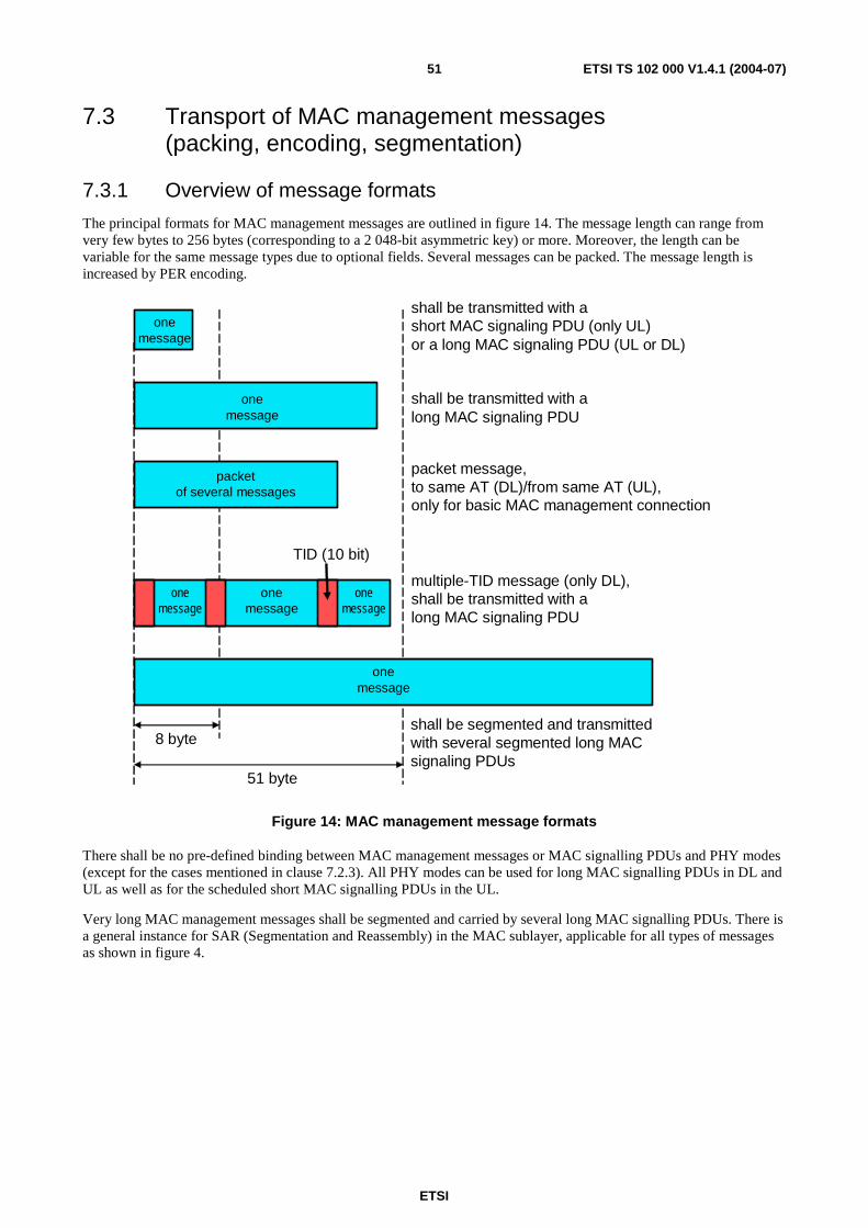
ETSI
ETSI TS 102 000 V1.4.1 (2004-07) 51
7.3 Transport of MAC management messages (packing, encoding, segmentation)
7.3.1 Overview of message formats
The principal formats for MAC management messages are outlined in figure 14. The message length can range from very few bytes to 256 bytes (corresponding to a 2 048-bit asymmetric key) or more. Moreover, the length can be variable for the same message types due to optional fields. Several messages can be packed. The message length is increased by PER encoding.
shall be transmitted with a short MAC signaling PDU (only UL)or a long MAC signaling PDU (UL or DL)
multiple-TID message (only DL),shall be transmitted with along MAC signaling PDU
shall be segmented and transmittedwith several segmented long MACsignaling PDUs
8 byte
51 byte
TID (10 bit)
onemessage
packet of several messages
onemessage
onemessage
onemessage
onemessage
onemessage
packet message,to same AT (DL)/from same AT (UL),only for basic MAC management connection
shall be transmitted with a long MAC signaling PDU
Figure 14: MAC management message formats
There shall be no pre-defined binding between MAC management messages or MAC signalling PDUs and PHY modes (except for the cases mentioned in clause 7.2.3). All PHY modes can be used for long MAC signalling PDUs in DL and UL as well as for the scheduled short MAC signalling PDUs in the UL.
Very long MAC management messages shall be segmented and carried by several long MAC signalling PDUs. There is a general instance for SAR (Segmentation and Reassembly) in the MAC sublayer, applicable for all types of messages as shown in figure 4.
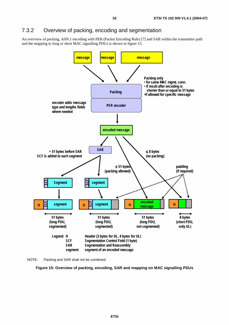
ETSI
ETSI TS 102 000 V1.4.1 (2004-07) 52
7.3.2 Overview of packing, encoding and segmentation
An overview of packing, ASN.1 encoding with PER (Packet Encoding Rule) [7] and SAR within the transmitter path and the mapping to long or short MAC signalling PDUs is shown in figure 15.
encoded message
message message
H
SAR
H
padding(if required)
51 bytes(long PDU, segmented)
51 bytes(long PDU,
not segmented)
8 bytes(short PDU,
only UL)
segment Hencodedmessage
Legend: H Header (3 bytes for DL, 4 bytes for UL)SCF Segmentation Control Field (1 byte)SAR Segmentation and Reassemblysegment segment of an encoded message
SCF
PER encoder
Packing
Packing only• for same MAC mgmt. conn.• if result after encoding is
shorter than or equal to 51 bytes•if allowed for specific message
> 51 bytes before SARSCF is added to each segment
≤≤≤≤ 8 bytes(no packing)
≤≤≤≤ 51 bytes(packing allowed)
encoder adds messagetype and lengths fieldswhere needed
message
SegmentSCF
H segmentSCF
SCF
segment
51 bytes(long PDU, segmented)
NOTE: Packing and SAR shall not be combined.
Figure 15: Overview of packing, encoding, SAR and mapping on MAC signalling PDUs
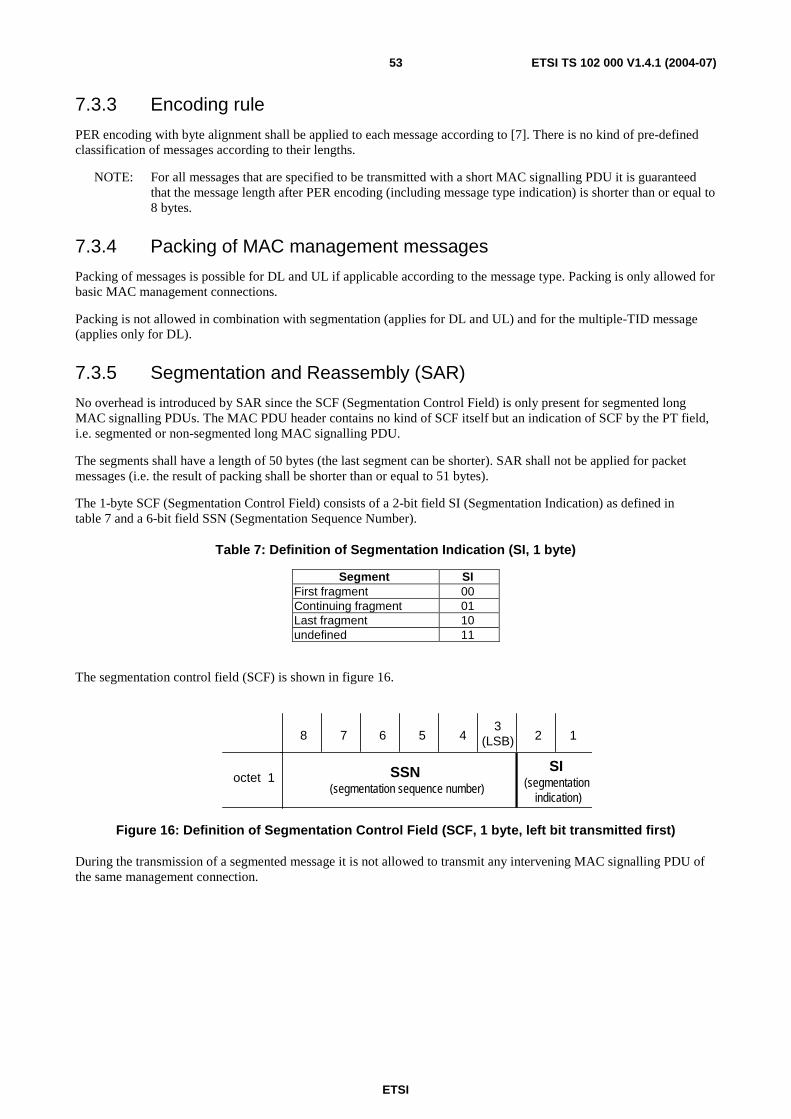
ETSI
ETSI TS 102 000 V1.4.1 (2004-07) 53
7.3.3 Encoding rule
PER encoding with byte alignment shall be applied to each message according to [7]. There is no kind of pre-defined classification of messages according to their lengths.
NOTE: For all messages that are specified to be transmitted with a short MAC signalling PDU it is guaranteed that the message length after PER encoding (including message type indication) is shorter than or equal to 8 bytes.
7.3.4 Packing of MAC management messages
Packing of messages is possible for DL and UL if applicable according to the message type. Packing is only allowed for basic MAC management connections.
Packing is not allowed in combination with segmentation (applies for DL and UL) and for the multiple-TID message (applies only for DL).
7.3.5 Segmentation and Reassembly (SAR)
No overhead is introduced by SAR since the SCF (Segmentation Control Field) is only present for segmented long MAC signalling PDUs. The MAC PDU header contains no kind of SCF itself but an indication of SCF by the PT field, i.e. segmented or non-segmented long MAC signalling PDU.
The segments shall have a length of 50 bytes (the last segment can be shorter). SAR shall not be applied for packet messages (i.e. the result of packing shall be shorter than or equal to 51 bytes).
The 1-byte SCF (Segmentation Control Field) consists of a 2-bit field SI (Segmentation Indication) as defined in table 7 and a 6-bit field SSN (Segmentation Sequence Number).
Table 7: Definition of Segmentation Indication (SI, 1 byte)
Segment SI First fragment 00 Continuing fragment 01 Last fragment 10 undefined 11
The segmentation control field (SCF) is shown in figure 16.
8 7 6 5 43
(LSB) 2
SSN(segmentation sequence number)
1
octet 1SI
(segmentationindication)
Figure 16: Definition of Segmentation Control Field (SCF, 1 byte, left bit transmitted first)
During the transmission of a segmented message it is not allowed to transmit any intervening MAC signalling PDU of the same management connection.

ETSI
ETSI TS 102 000 V1.4.1 (2004-07) 54
7.4 List of protocol primitives and mapping of messages to connections (normative)
7.4.1 List of all MAC management messages
Table 8 provides an overview and a short description of all MAC management messages. The detailed message contents are given in annex B.
Legend for "connection" column in table 8 :
• 0 = broadcast (only for DL).
• 1 = basic MAC management connection (AT-specific).
• 2 = primary MAC management connection (AT-specific).
• 3 = secondary management connection (AT-specific).
• p = allowed for packing.
• m = allowed for multiple-TID message.
• R-NR = direction from requesting to non-requesting entity.
• NR-R = direction from non-requesting to requesting entity.
Table 8: List of MAC management messages (protocol primitives)
Name Direction Connection Description and remarks Broadcast messages
RlcGeneralBroadcastInformation (GBI message)
DL 0 Broadcast information (Frequencies, operation modes, frame offset, contention resolution parameters, timers, PHY mode set descriptor(s)
RlcFrequencyList DL 0 Frequency list RlcMultipleTidBroadcastBasic DL 0 Addresses several ATs, contains a packet of (TID,
basic MAC management message) pairs Request-grant messages
RlcBandwidthReq UL 1 Bandwidth request, shall be used in granted short PDUs or in bandwidth request contention window
RlcQueueStatusReq DL 1, p, m Request to report the queue status of listed CAs RlcQueueStatusRsp UL 1 Response, containing the queue lengths, to be
transmitted in next granted short PDU Initialization control messages
RlcRangingInvitation DL 1 Invitation to initial ranging (binding between MAC address and TID, allocation of CIDs, start of ranging). Multiple-TID message not possible
RlcRangingReq UL 1 Ranging request in granted UL ranging burst, contains formally EGT, transmitted with increasing or adapted power
RlcRangingContinue DL 1, m Response from AP, contains power and timing offset information and indicates continuation of ranging
RlcRangingSuccess DL 1, m Response from AP, contains power and timing offset information and indicates termination of ranging, informs about termination of initialization
RlcRangingAck UL 1 Acknowledgement of reception of RlcRangingSuccess, in granted UL ranging burst
RlcPhyCapabilitiesReq DL 1, p, m AP request to send RlcPhyCapabilitiesInfo RlcPhyCapabilitiesInfo UL 1
non-PTC AT informs about its optional PHY capabilities, PTC not allowed
RlcPhyCapabilitiesCnf DL 1, p, m AP commands PHY features to be used, informs about termination of initialization
RlcOtherCapabilitiesReq DL 1, p, m AP request to send RlcOtherCapabilitiesInfo
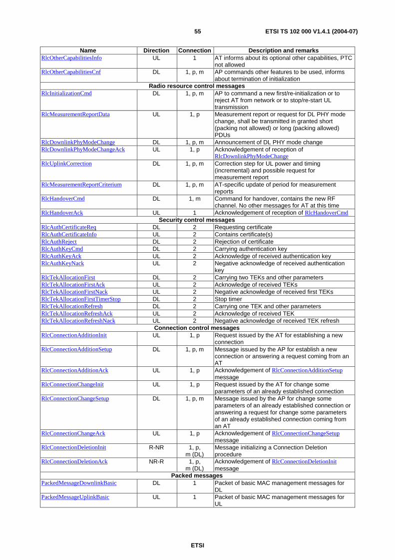
ETSI
ETSI TS 102 000 V1.4.1 (2004-07) 55
Name Direction Connection Description and remarks RlcOtherCapabilitiesInfo UL 1 AT informs about its optional other capabilities, PTC
not allowed RlcOtherCapabilitiesCnf DL 1, p, m AP commands other features to be used, informs
about termination of initialization Radio resource control messages
RlcInitializationCmd DL 1, p, m AP to command a new first/re-initialization or to reject AT from network or to stop/re-start UL transmission
RlcMeasurementReportData UL 1, p Measurement report or request for DL PHY mode change, shall be transmitted in granted short (packing not allowed) or long (packing allowed) PDUs
RlcDownlinkPhyModeChange DL 1, p, m Announcement of DL PHY mode change RlcDownlinkPhyModeChangeAck UL 1, p Acknowledgement of reception of
RlcDownlinkPhyModeChange RlcUplinkCorrection DL 1, p, m Correction step for UL power and timing
(incremental) and possible request for measurement report
RlcMeasurementReportCriterium DL 1, p, m AT-specific update of period for measurement reports
RlcHandoverCmd DL 1, m Command for handover, contains the new RF channel. No other messages for AT at this time
RlcHandoverAck UL 1 Acknowledgement of reception of RlcHandoverCmd Security control messages
RlcAuthCertificateReq DL 2 Requesting certificate RlcAuthCertificateInfo UL 2 Contains certificate(s) RlcAuthReject DL 2 Rejection of certificate RlcAuthKeyCmd DL 2 Carrying authentication key RlcAuthKeyAck UL 2 Acknowledge of received authentication key RlcAuthKeyNack UL 2 Negative acknowledge of received authentication
key RlcTekAllocationFirst DL 2 Carrying two TEKs and other parameters RlcTekAllocationFirstAck UL 2 Acknowledge of received TEKs RlcTekAllocationFirstNack UL 2 Negative acknowledge of received first TEKs RlcTekAllocationFirstTimerStop DL 2 Stop timer RlcTekAllocationRefresh DL 2 Carrying one TEK and other parameters RlcTekAllocationRefreshAck UL 2 Acknowledge of received TEK RlcTekAllocationRefreshNack UL 2 Negative acknowledge of received TEK refresh
Connection control messages RlcConnectionAdditionInit UL 1, p Request issued by the AT for establishing a new
connection RlcConnectionAdditionSetup DL 1, p, m Message issued by the AP for establish a new
connection or answering a request coming from an AT
RlcConnectionAdditionAck UL 1, p Acknowledgement of RlcConnectionAdditionSetup message
RlcConnectionChangeInit UL 1, p Request issued by the AT for change some parameters of an already established connection
RlcConnectionChangeSetup DL 1, p, m Message issued by the AP for change some parameters of an already established connection or answering a request for change some parameters of an already established connection coming from an AT
RlcConnectionChangeAck UL 1, p Acknowledgement of RlcConnectionChangeSetup message
RlcConnectionDeletionInit R-NR 1, p, m (DL)
Message initializing a Connection Deletion procedure
RlcConnectionDeletionAck NR-R 1, p, m (DL)
Acknowledgement of RlcConnectionDeletionInit message
Packed messages PackedMessageDownlinkBasic DL 1 Packet of basic MAC management messages for
DL PackedMessageUplinkBasic UL 1 Packet of basic MAC management messages for
UL
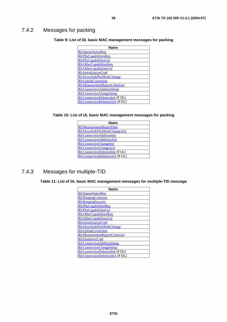
ETSI
ETSI TS 102 000 V1.4.1 (2004-07) 56
7.4.2 Messages for packing
Table 9: List of DL basic MAC management messages for packing
Name RlcQueueStatusReq RlcPhyCapabilitiesReq RlcPhyCapabilitiesCnf RlcOtherCapabilitiesReq RlcOtherCapabilitiesCnf RlcInitializationCmd RlcDownlinkPhyModeChange RlcUplinkCorrection RlcMeasurementReportCriterium RlcConnectionAdditionSetup RlcConnectionChangeSetup RlcConnectionDeletionInit (if DL) RlcConnectionDeletionAck (if DL)
Table 10: List of UL basic MAC management messages for packing
Name RlcMeasurementReportData RlcDownlinkPhyModeChangeAck RlcConnectionAdditionInit RlcConnectionAdditionAck RlcConnectionChangeInit RlcConnectionChangeAck RlcConnectionDeletionInit (if UL) RlcConnectionDeletionAck (if UL)
7.4.3 Messages for multiple-TID
Table 11: List of DL basic MAC management messages for multiple-TID message
Name RlcQueueStatusReq RlcRangingContinue RlcRangingSuccess RlcPhyCapabilitiesReq RlcPhyCapabilitiesCnf RlcOtherCapabilitiesReq RlcOtherCapabilitiesCnf RlcInitializationCmd RlcDownlinkPhyModeChange RlcUplinkCorrection RlcMeasurementReportCriterium RlcHandoverCmd RlcConnectionAdditionSetup RlcConnectionChangeSetup RlcConnectionDeletionInit (if DL) RlcConnectionDeletionAck (if DL)

ETSI
ETSI TS 102 000 V1.4.1 (2004-07) 57
7.4.4 Overview of Connections
Table 12: Overview of connections and related parameters
Connection type Direction Identification PHY mode
UL PDU length
PT
Multicast data DL MulticastCid (per AT group) all - 0 Unicast data both UnicastCid (per AT) all L 0 basic MAC mgmt both BasicCid = BasicCaid (per AT) all L or S 1, 2, 4 primary MAC mgmt both PrimaryCid = PrimaryCaid (per
AT) all L or S 1, 2, 4
secondary mgmt both SecondaryCid (per AT) all L 0 broadcast (e.g. GBI message)
DL BroadcastCid=0 1 - 1
control zone (not a connection)
DL frame preamble, DIUC, UIUC, EndOfMapTid=1
0 - n/a
multiple-TID DL BroadcastBasicCid=1 only basic MAC mgmt messages
all - 1
ranging invitation DL RangingCid=4 (per AT) message allocated to basic mgmt
1 - 1
Contention window (RlcBandwidthRequest)
UL ContentionWindowTid=0 message allocated to basic mgmt
1 S 4
MAC dummy PDU (not a connection)
both DummyCid=3 (per AT) all L or S 3, 5
Legend: UL PDU length: L=long, S=short
PT: 0=data, 1=long non-seg, 2=long seg, 3=long dummy, 4=short, 5=short dummy
NOTE: All data and management connections can be allocated to connection aggregates. Multiple-TID messages, the ranging request message carried in the ranging burst and the bandwidth request message carried in the contention window are allocated to the basic MAC management connection. Such an allocation does not exist for MAC dummy PDUs.
Table 13 summarizes the use of short and long MAC signalling PDUs and the relation to some other properties like applicability of packing, multiple-TID, etc.
Table 13: Use of short and long signalling PDUs
Message Direc-tion
Long or short PDU
Packing allowed
Multiple-TID allowed
DL only
Contention window allowed
UL only
Use of (PM,RSB,PB)
UL only
PHY mode allowed
RlcRangingReq, RlcRangingAck
UL short No - No No only #1 (ranging burst)
RlcBandwidthReq UL short No - Yes (or Granted)
Yes only #1 for contention window;
all for granted PDU
RlcQueueStatusRsp UL short No - No Yes all RlcMeasurementReportData
UL short or
long
No for short; Yes for long
- No Yes all
Other messages that fit into one short PDU
UL short or
long
No for short
Yes for long
- No Yes all
Other messages that fit into one long PDU
both long see lists in clause 7.4.2
see list in clause 7.4.3
No Yes all
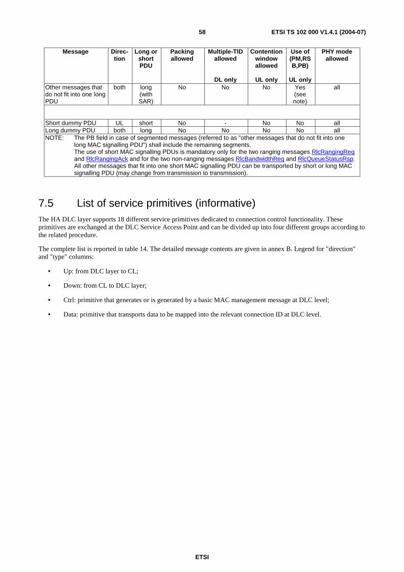
ETSI
ETSI TS 102 000 V1.4.1 (2004-07) 58
Message Direc-tion
Long or short PDU
Packing allowed
Multiple-TID allowed
DL only
Contention window allowed
UL only
Use of (PM,RSB,PB)
UL only
PHY mode allowed
Other messages that do not fit into one long PDU
both long (with SAR)
No No No Yes (see note)
all
Short dummy PDU UL short No - No No all Long dummy PDU both long No No No No all NOTE: The PB field in case of segmented messages (referred to as "other messages that do not fit into one
long MAC signalling PDU") shall include the remaining segments. The use of short MAC signalling PDUs is mandatory only for the two ranging messages RlcRangingReq and RlcRangingAck and for the two non-ranging messages RlcBandwidthReq and RlcQueueStatusRsp. All other messages that fit into one short MAC signalling PDU can be transported by short or long MAC signalling PDU (may change from transmission to transmission).
7.5 List of service primitives (informative) The HA DLC layer supports 18 different service primitives dedicated to connection control functionality. These primitives are exchanged at the DLC Service Access Point and can be divided up into four different groups according to the related procedure.
The complete list is reported in table 14. The detailed message contents are given in annex B. Legend for "direction" and "type" columns:
• Up: from DLC layer to CL;
• Down: from CL to DLC layer;
• Ctrl: primitive that generates or is generated by a basic MAC management message at DLC level;
• Data: primitive that transports data to be mapped into the relevant connection ID at DLC level.
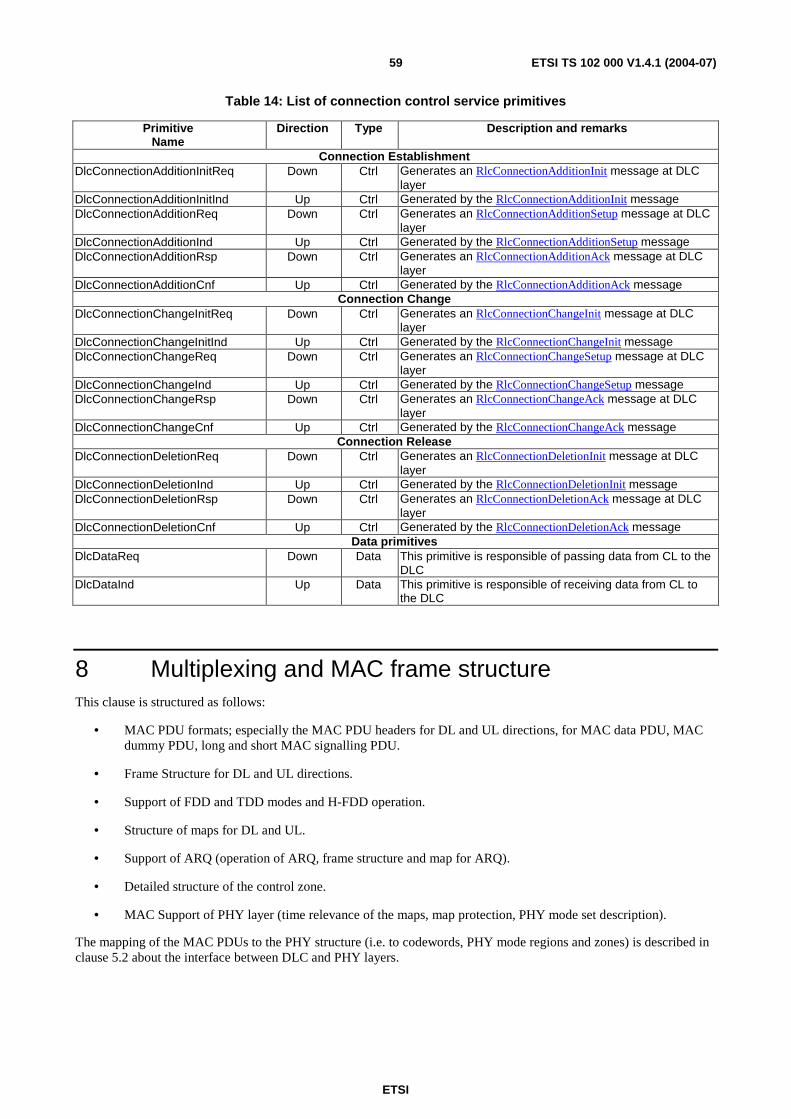
ETSI
ETSI TS 102 000 V1.4.1 (2004-07) 59
Table 14: List of connection control service primitives
Primitive Name
Direction Type Description and remarks
Connection Establishment DlcConnectionAdditionInitReq Down Ctrl Generates an RlcConnectionAdditionInit message at DLC
layer DlcConnectionAdditionInitInd Up Ctrl Generated by the RlcConnectionAdditionInit message DlcConnectionAdditionReq Down Ctrl Generates an RlcConnectionAdditionSetup message at DLC
layer DlcConnectionAdditionInd Up Ctrl Generated by the RlcConnectionAdditionSetup message DlcConnectionAdditionRsp Down Ctrl Generates an RlcConnectionAdditionAck message at DLC
layer DlcConnectionAdditionCnf Up Ctrl Generated by the RlcConnectionAdditionAck message
Connection Change DlcConnectionChangeInitReq Down Ctrl Generates an RlcConnectionChangeInit message at DLC
layer DlcConnectionChangeInitInd Up Ctrl Generated by the RlcConnectionChangeInit message DlcConnectionChangeReq Down Ctrl Generates an RlcConnectionChangeSetup message at DLC
layer DlcConnectionChangeInd Up Ctrl Generated by the RlcConnectionChangeSetup message DlcConnectionChangeRsp Down Ctrl Generates an RlcConnectionChangeAck message at DLC
layer DlcConnectionChangeCnf Up Ctrl Generated by the RlcConnectionChangeAck message
Connection Release DlcConnectionDeletionReq Down Ctrl Generates an RlcConnectionDeletionInit message at DLC
layer DlcConnectionDeletionInd Up Ctrl Generated by the RlcConnectionDeletionInit message DlcConnectionDeletionRsp Down Ctrl Generates an RlcConnectionDeletionAck message at DLC
layer DlcConnectionDeletionCnf Up Ctrl Generated by the RlcConnectionDeletionAck message
Data primitives DlcDataReq Down Data This primitive is responsible of passing data from CL to the
DLC DlcDataInd Up Data This primitive is responsible of receiving data from CL to
the DLC
8 Multiplexing and MAC frame structure This clause is structured as follows:
• MAC PDU formats; especially the MAC PDU headers for DL and UL directions, for MAC data PDU, MAC dummy PDU, long and short MAC signalling PDU.
• Frame Structure for DL and UL directions.
• Support of FDD and TDD modes and H-FDD operation.
• Structure of maps for DL and UL.
• Support of ARQ (operation of ARQ, frame structure and map for ARQ).
• Detailed structure of the control zone.
• MAC Support of PHY layer (time relevance of the maps, map protection, PHY mode set description).
The mapping of the MAC PDUs to the PHY structure (i.e. to codewords, PHY mode regions and zones) is described in clause 5.2 about the interface between DLC and PHY layers.

ETSI
ETSI TS 102 000 V1.4.1 (2004-07) 60
8.1 MAC PDU format
8.1.1 Overview
The MAC PDU is the data unit exchanged between the MAC sublayers of AP and AT. The MAC PDU shall have a fixed length in bytes, but a variable duration and a variable length in symbols due to the use of adaptive PHY mode (i.e. adaptive modulation and coding schemes).
Four MAC PDU types are defined, each consisting of the MAC PDU payload part and the MAC PDU header as shown in figures 6 and 7:
• MAC data PDU: shall be used to carry unicast data (both directions, also including the secondary management connection) or multicast data (DL) only. The total length is 54 bytes for DL and 55 bytes for UL where for both directions the traffic payload is fixed to 51 bytes. In case of a cell-based CL, this is suitable for carrying ATM cells, corresponding to 48 bytes ATM payload plus 3 bytes header (i.e. full ATM header except HEC and VPI field).
• MAC dummy PDU: the long MAC dummy PDU is a specific MAC PDU with the same total length as the MAC data PDU to fill up the DL TDM zone if not enough MAC PDUs are to be transmitted or to fill up an UL burst if more MAC PDU have been granted than are available for transmission. The short MAC dummy PDU exists only in the UL with a total length of 12 bytes and is used if more grants for short PDUs are given than short MAC signalling PDUs are available for transmission.
• Long MAC signalling PDU (carrying broadcast, basic or primary MAC management messages): shall have the same length as the MAC data PDU with 51 bytes for the payload part. Two subtypes have to be distinguished (both for DL and UL):
- The segmented long MAC signalling PDU shall be used to carry the segments of long (unpacked) messages after SAR, i.e. the PT field in the PDU header indicates that the first byte of the payload contains segmentation information. The length of the segments itself are limited to 50 bytes.
- The non-segmented long MAC signalling PDU shall be used to carry one message or a packet of several messages. The length of the payload is limited to 51 bytes.
• Short MAC signalling PDU (carrying basic or primary MAC management messages): carries only one message, exits only in the UL. The payload length is 8 bytes and the total length is 12 bytes.
Encryption for privacy is only applied for MAC data PDUs (i.e. PT = 000 shall be fulfilled) and only for the 51 bytes of the payload part and only for unicast data connections.
8.1.2 MAC PDU header
The MAC PDU headers for DL and UL transmissions are different and shown in table 15 for the DL with a length of 3 bytes (applies for MAC data PDU, MAC dummy PDU, long MAC signalling PDU) and table 16 for the UL with a length of 4 bytes (applies for MAC data PDU, MAC dummy PDU, long MAC signalling PDU, short MAC signalling PDU). The difference in the length is caused by the additional GM field required in the UL header.
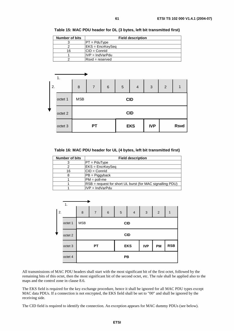
ETSI
ETSI TS 102 000 V1.4.1 (2004-07) 61
Table 15: MAC PDU header for DL (3 bytes, left bit transmitted first)
Number of bits Field description 3 PT = PduType 2 EKS = EncrKeySeq
16 CID = ConnId 1 IVP = IndVarPdu 2 Rsvd = reserved
8 7 6 5 4 3 2 1
CID
CID
IVPEKSPT Rsvd
octet 1
octet 2
octet 3
MSB
1.
2.
Table 16: MAC PDU header for UL (4 bytes, left bit transmitted first)
Number of bits Field description 3 PT = PduType 2 EKS = EncrKeySeq
16 CID = ConnId 8 PB = Piggyback 1 PM = poll-me 1 RSB = request for short UL burst (for MAC signalling PDU) 1 IVP = IndVarPdu
8 7 6 5 4 3 2 1
CID
CID
IVPEKSPT PM RSB
PB
octet 1
octet 2
octet 3
octet 4
MSB
1.
2.
All transmissions of MAC PDU headers shall start with the most significant bit of the first octet, followed by the remaining bits of this octet, then the most significant bit of the second octet, etc. The rule shall be applied also to the maps and the control zone in clause 8.6.
The EKS field is required for the key exchange procedure, hence it shall be ignored for all MAC PDU types except MAC data PDUs. If a connection is not encrypted, the EKS field shall be set to "00" and shall be ignored by the receiving side.
The CID field is required to identify the connection. An exception appears for MAC dummy PDUs (see below).
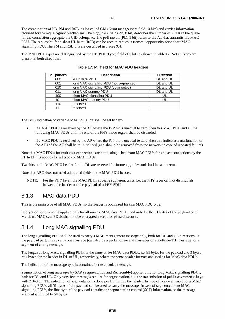
ETSI
ETSI TS 102 000 V1.4.1 (2004-07) 62
The combination of PB, PM and RSB is also called GM (Grant management field 10 bits) and carries information required for the request-grant mechanism. The piggyback field (PB, 8 bit) describes the number of PDUs in the queue for the connection aggregate the CID belongs to. The poll-me bit (PM, 1 bit) refers to the AT that transmits the MAC PDU. The request bit for a short UL burst (RSB) can be used to request a transmit opportunity for a short MAC signalling PDU. The PM and RSB bits are described in clause 9.4.
The MAC PDU types are distinguished by the PT (PDU Type) field of 3 bits as shown in table 17. Not all types are present in both directions.
Table 17: PT field for MAC PDU headers
PT pattern Description Direction 000 MAC data PDU DL and UL 001 long MAC signalling PDU (not segmented) DL and UL 010 long MAC signalling PDU (segmented) DL and UL 011 long MAC dummy PDU DL and UL 100 short MAC signalling PDU UL 101 short MAC dummy PDU UL 110 reserved 111 reserved
The IVP (Indication of variable MAC PDU) bit shall be set to zero.
• If a MAC PDU is received by the AT where the IVP bit is unequal to zero, then this MAC PDU and all the following MAC PDUs until the end of the PHY mode region shall be discarded.
• If a MAC PDU is received by the AP where the IVP bit is unequal to zero, then this indicates a malfunction of the AT and the AT shall be re-initialized (and should be removed from the network in case of repeated failure).
Note that MAC PDUs for multicast connections are not distinguished from MAC PDUs for unicast connections by the PT field, this applies for all types of MAC PDUs.
Two bits in the MAC PDU header for the DL are reserved for future upgrades and shall be set to zero.
Note that ARQ does not need additional fields in the MAC PDU header.
NOTE: For the PHY layer, the MAC PDUs appear as coherent units, i.e. the PHY layer can not distinguish between the header and the payload of a PHY SDU.
8.1.3 MAC data PDU
This is the main type of all MAC PDUs, so the header is optimized for this MAC PDU type.
Encryption for privacy is applied only for all unicast MAC data PDUs, and only for the 51 bytes of the payload part. Multicast MAC data PDUs shall not be encrypted except for phase 3 security.
8.1.4 Long MAC signalling PDU
The long signalling PDU shall be used to carry a MAC management message only, both for DL and UL directions. In the payload part, it may carry one message (can also be a packet of several messages or a multiple-TID message) or a segment of a long message.
The length of long MAC signalling PDUs is the same as for MAC data PDUs, i.e. 51 bytes for the payload and 3 bytes or 4 bytes for the header in DL or UL, respectively, where the same header formats are used as for MAC data PDUs.
The indication of the message type is contained in the encoded message.
Segmentation of long messages by SAR (Segmentation and Reassembly) applies only for long MAC signalling PDUs, both for DL and UL. Only very few messages require for segmentation, e.g. the transmission of public asymmetric keys with 2 048 bit. The indication of segmentation is done per PT field in the header. In case of non-segmented long MAC signalling PDUs, all 51 bytes of the payload can be used to carry the message. In case of segmented long MAC signalling PDUs, the first byte of the payload contains the segmentation control (SCF) information, so the message segment is limited to 50 bytes.
ETSI
ETSI TS 102 000 V1.4.1 (2004-07) 63
The payload of long MAC signalling PDUs shall not be encrypted.
8.1.5 Short MAC signalling PDU
The short MAC signalling PDU shall be used to carry signalling messages only. They are only used in the UL direction.
The length of short MAC signalling PDUs is 8 bytes for the payload plus 4 bytes for the header, where the same header format is used as for MAC data PDUs or long MAC signalling PDUs in the UL.
NOTE: In some cases the type of the message is known in advance from the appearance in a specific window (e.g. bandwidth request message in bandwidth request contention window).
The payload of short MAC signalling PDUs shall not be encrypted.
8.1.6 Long and short MAC dummy PDU
MAC dummy PDUs are generated in the DLC layer.
The payload and header format of long MAC dummy PDUs is identical to the MAC data PDU format. The long MAC dummy PDU shall be used in DL or UL to fill up:
• The DL TDM zone if not enough MAC data PDUs are to be transmitted. They can be transmitted with any PHY mode, i.e. within any PHY mode region of the TDM or TDMA zone.
• An UL burst if more MAC PDU have been granted than are available for transmission (usually, the AP scheduler knows the number of MAC PDU in the AT, however, it is possible that grants are given for ARQ re-transmissions which cannot be used for non-ARQ connections).
The payload and header format of short MAC dummy PDUs is identical to the short MAC signalling data PDU format. The short MAC dummy PDU shall be used in the UL to fill up:
• An UL burst if more grants for short PDUs have been received than are required for transmission of short MAC signalling PDUs.
Grants for long or short PDUs can also be given by the AP to enforce the AT to transmit in any case. The AT shall transmit if grants are received, maybe with long or short (according to the grant) MAC dummy PDUs (if no other data is available). This allows the AP to measure the properties of the UL radio link.
The content of the header of all MAC dummy PDUs is ignored in the receiver after reading the PT field. A MAC dummy PDU shall be both marked by the PT field and a specific "MAC dummy CID".
The 51 byte payload of a long MAC dummy PDU shall be identical to an ATM idle cell, i.e. the first three bytes corresponding to the compressed ATM header shall be zero with the exception of 1 for the CLP bit, and the content of the information field is 0110 1010 repeated 48 times.
The 8-byte payload of a short MAC dummy PDU shall be set to zero.
MAC dummy PDUs shall not be encrypted.
8.2 Frame structure The frame structure shall be flexible enough to support either the FDD or the TDD operational mode. With reference to the FDD mode, the frame structure gives the possibility to support in the same frame both the FDD ATs as well as the H-FDD ATs.
The transmissions of AP and AT shall be structured in frames of fixed length. The frame structure is relevant for the DLC layer (especially with regards to scheduling and multiplexing) as well as for the PHY layer (especially with regards to synchronization and preambles). The frame duration shall be fixed to 1 ms, both for DL and UL directions, and shall be independent of the FDD and TDD mode and the H-FDD operation.

ETSI
ETSI TS 102 000 V1.4.1 (2004-07) 64
For FDD, the frames for DL and UL shall be synchronized in time with a fixed Frame Offset (FO), where FO is configurable by the AP. An offset of zero would mean an exact alignment at the AP antenna, (i.e. the UL frame starts at the same time as the DL frame starts), however, the minimum FO shall be at least 0,4 ms, since this corresponds to about the maximum length of the control zone in DL under worst-case conditions, i.e. the UL frame does not start earlier than the end of the UL map where also some extra time for the decoding of the UL map should be spent. Formally, FO is not defined for TDD systems.
The basic multiple access scheme shall be TDM for the DL and TDMA for the UL. Optionally, a TDMA zone for the DL is possible in addition to the regular TDM zone.
8.2.1 Frame structure for downlink
The DL frame consists of the DL frame preamble, the control zone with a variable length, the TDM zone and the optional TDMA zone as described in figure 17 (see also the figures in clauses 5.2.2 and 5.2.3 describing the DLC-PHY interface). The length of the TDM zone (in case of TDM only) or the lengths of TDM and TDMA zones (in case of additional TDMA) are variable.
ControlZone
PHY mode#1
region
PHY mode#2
region
PHY mode#3
regionOptional TDMA Regions
Downlinkmap
Uplinkmap
PHY mode#X
region
PHY mode#Z
region
PHY mode#Y
region
TDM zoneFrame
Preamble TDMA zone
ARQmap
BroadcastFrame
Info
Startingsymbols
Framepadding
BurstPreamble
Figure 17: Maps and basic DL frame structure with TDMA option
The DL data to different ATs shall be multiplexed in the time domain (TDM). The TDM zone of the DL frame consists of a few TDM regions (with the same PHY mode in one region) in a robustness descending order (PHY mode #1, #2, etc.), where the number of regions is given by the cardinality of the PHY mode set. The control zone at the beginning of the DL frame shall be transmitted with the most robust PHY mode #0 to allow the reception of the control zone by all ATs.
TDMA regions are optionally present on the DL. In this case, an AT (supporting TDMA) may be assigned to receive DL transmissions either in a TDM region as previously described or in a TDMA region. The TDMA region allocations shall be broadcasted as part of the DL map. The AP scheduler could use the DL TDMA feature as it increases channel utilization and minimizes latencies. Note that a TDMA region may serve more than one AT by time division multiplexing DL data to several ATs.
A DL burst in the TDMA zone constitutes FEC blocks of a specific PHY mode, i.e. the DL burst corresponds to a PHY mode region plus the preamble of the PHY mode region. A DL burst can serve several ATs. Several DL bursts with the same PHY mode can appear.
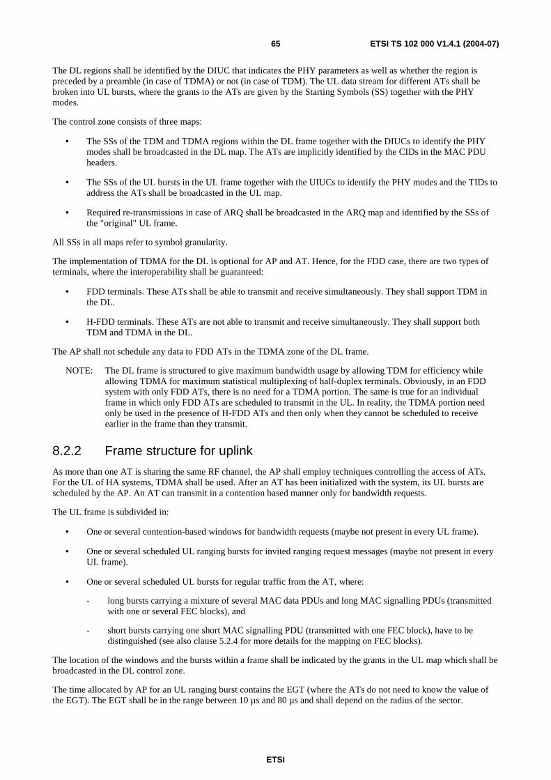
ETSI
ETSI TS 102 000 V1.4.1 (2004-07) 65
The DL regions shall be identified by the DIUC that indicates the PHY parameters as well as whether the region is preceded by a preamble (in case of TDMA) or not (in case of TDM). The UL data stream for different ATs shall be broken into UL bursts, where the grants to the ATs are given by the Starting Symbols (SS) together with the PHY modes.
The control zone consists of three maps:
• The SSs of the TDM and TDMA regions within the DL frame together with the DIUCs to identify the PHY modes shall be broadcasted in the DL map. The ATs are implicitly identified by the CIDs in the MAC PDU headers.
• The SSs of the UL bursts in the UL frame together with the UIUCs to identify the PHY modes and the TIDs to address the ATs shall be broadcasted in the UL map.
• Required re-transmissions in case of ARQ shall be broadcasted in the ARQ map and identified by the SSs of the "original" UL frame.
All SSs in all maps refer to symbol granularity.
The implementation of TDMA for the DL is optional for AP and AT. Hence, for the FDD case, there are two types of terminals, where the interoperability shall be guaranteed:
• FDD terminals. These ATs shall be able to transmit and receive simultaneously. They shall support TDM in the DL.
• H-FDD terminals. These ATs are not able to transmit and receive simultaneously. They shall support both TDM and TDMA in the DL.
The AP shall not schedule any data to FDD ATs in the TDMA zone of the DL frame.
NOTE: The DL frame is structured to give maximum bandwidth usage by allowing TDM for efficiency while allowing TDMA for maximum statistical multiplexing of half-duplex terminals. Obviously, in an FDD system with only FDD ATs, there is no need for a TDMA portion. The same is true for an individual frame in which only FDD ATs are scheduled to transmit in the UL. In reality, the TDMA portion need only be used in the presence of H-FDD ATs and then only when they cannot be scheduled to receive earlier in the frame than they transmit.
8.2.2 Frame structure for uplink
As more than one AT is sharing the same RF channel, the AP shall employ techniques controlling the access of ATs. For the UL of HA systems, TDMA shall be used. After an AT has been initialized with the system, its UL bursts are scheduled by the AP. An AT can transmit in a contention based manner only for bandwidth requests.
The UL frame is subdivided in:
• One or several contention-based windows for bandwidth requests (maybe not present in every UL frame).
• One or several scheduled UL ranging bursts for invited ranging request messages (maybe not present in every UL frame).
• One or several scheduled UL bursts for regular traffic from the AT, where:
- long bursts carrying a mixture of several MAC data PDUs and long MAC signalling PDUs (transmitted with one or several FEC blocks), and
- short bursts carrying one short MAC signalling PDU (transmitted with one FEC block), have to be distinguished (see also clause 5.2.4 for more details for the mapping on FEC blocks).
The location of the windows and the bursts within a frame shall be indicated by the grants in the UL map which shall be broadcasted in the DL control zone.
The time allocated by AP for an UL ranging burst contains the EGT (where the ATs do not need to know the value of the EGT). The EGT shall be in the range between 10 µs and 80 µs and shall depend on the radius of the sector.
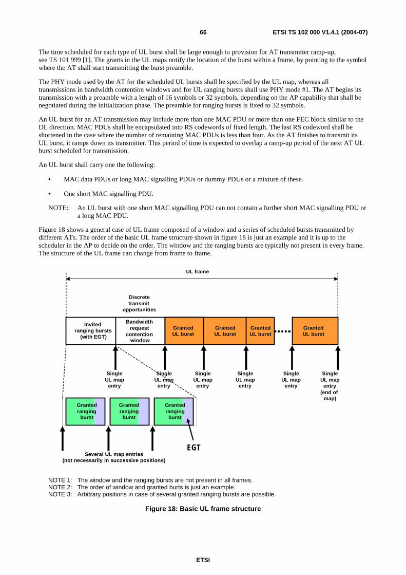
ETSI
ETSI TS 102 000 V1.4.1 (2004-07) 66
The time scheduled for each type of UL burst shall be large enough to provision for AT transmitter ramp-up, see TS 101 999 [1]. The grants in the UL maps notify the location of the burst within a frame, by pointing to the symbol where the AT shall start transmitting the burst preamble.
The PHY mode used by the AT for the scheduled UL bursts shall be specified by the UL map, whereas all transmissions in bandwidth contention windows and for UL ranging bursts shall use PHY mode #1. The AT begins its transmission with a preamble with a length of 16 symbols or 32 symbols, depending on the AP capability that shall be negotiated during the initialization phase. The preamble for ranging bursts is fixed to 32 symbols.
An UL burst for an AT transmission may include more than one MAC PDU or more than one FEC block similar to the DL direction. MAC PDUs shall be encapsulated into RS codewords of fixed length. The last RS codeword shall be shortened in the case where the number of remaining MAC PDUs is less than four. As the AT finishes to transmit its UL burst, it ramps down its transmitter. This period of time is expected to overlap a ramp-up period of the next AT UL burst scheduled for transmission.
An UL burst shall carry one the following:
• MAC data PDUs or long MAC signalling PDUs or dummy PDUs or a mixture of these.
• One short MAC signalling PDU.
NOTE: An UL burst with one short MAC signalling PDU can not contain a further short MAC signalling PDU or a long MAC PDU.
Figure 18 shows a general case of UL frame composed of a window and a series of scheduled bursts transmitted by different ATs. The order of the basic UL frame structure shown in figure 18 is just an example and it is up to the scheduler in the AP to decide on the order. The window and the ranging bursts are typically not present in every frame. The structure of the UL frame can change from frame to frame.
GrantedUL burst
Invited ranging bursts
(with EGT)
Bandwidthrequest
contentionwindow
GrantedUL burst
UL frame
GrantedUL burst
Grantedranging
burst
Grantedranging
burst
Grantedranging
burst
EGT
Discretetransmit
opportunities
SingleUL map
entry
SingleUL map
entry
Several UL map entries(not necessarily in successive positions)
GrantedUL burst
SingleUL map
entry
SingleUL map
entry
SingleUL map
entry
SingleUL map
entry(end of
map)
NOTE 1: The window and the ranging bursts are not present in all frames. NOTE 2: The order of window and granted burts is just an example. NOTE 3: Arbitrary positions in case of several granted ranging bursts are possible.
Figure 18: Basic UL frame structure
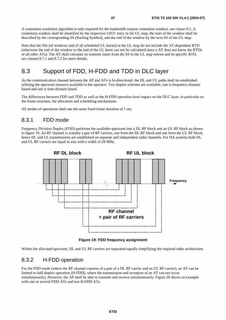
ETSI
ETSI TS 102 000 V1.4.1 (2004-07) 67
A contention resolution algorithm is only required for the bandwidth request contention window, see clause 9.5. A contention window shall be identified by the respective UIUC entry in the UL map, the start of the window shall be described by the corresponding SS (Starting Symbol), and the end of the window by the next SS of the UL map.
Note that the SSs (of windows and of all scheduled UL bursts) in the UL map do not include the AT-dependent RTD (otherwise the end of the window or the end of the UL burst can not be calculated since a AT does not know the RTDs of all other ATs). The AT shall calculate its transmit times from the SS in the UL map entries and its specific RTD, see clauses 8.7.1 and 8.7.2 for more details.
8.3 Support of FDD, H-FDD and TDD in DLC layer As the communication channel between the AP and ATs is bi-directional, the DL and UL paths shall be established utilizing the spectrum resource available to the operator. Two duplex schemes are available, one is frequency-domain based and one is time-domain based.
The differences between FDD and TDD as well as the H-FDD operation have impact on the DLC layer, in particular on the frame structure, the allocation and scheduling mechanisms.
All modes of operations shall use the same fixed frame duration of 1 ms.
8.3.1 FDD mode
Frequency Division Duplex (FDD) partitions the available spectrum into a DL RF block and an UL RF block as shown in figure 19. An RF channel is actually a pair of RF carriers, one from the DL RF block and one form the UL RF block, hence DL and UL transmissions are established on separate and independent radio channels. For HA systems both DL and UL RF carriers are equal in size with a width of 28 MHz.
RF DL block RF UL block
Frequency
RF channel= pair of RF carriers
Figure 19: FDD frequency assignment
Within the allocated spectrum, DL and UL RF carriers are separated equally simplifying the required radio architecture.
8.3.2 H-FDD operation
For the FDD mode (where the RF channel consists of a pair of a DL RF carrier and an UL RF carrier), an AT can be limited to half-duplex operation (H-FDD), where the transmission and reception of an AT can not occur simultaneously). However, the AP shall be able to transmit and receive simultaneously. Figure 20 shows an example with one or several FDD ATs and two H-FDD ATs.
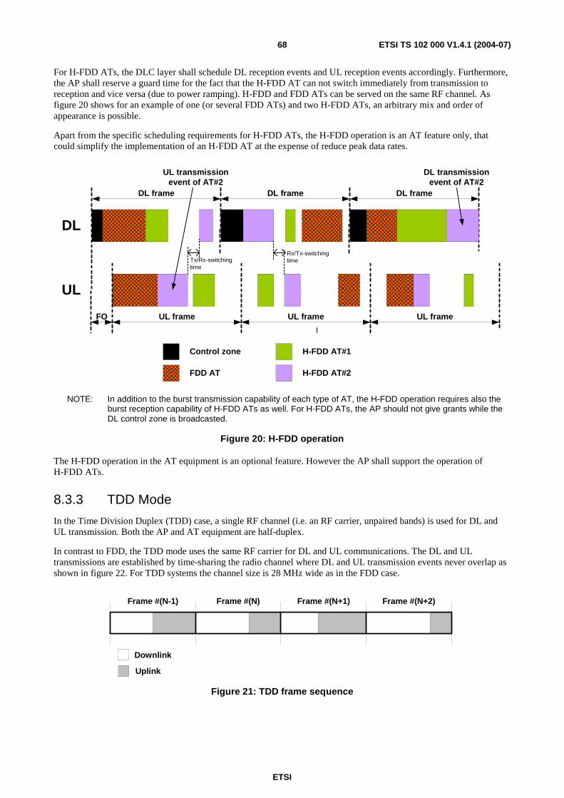
ETSI
ETSI TS 102 000 V1.4.1 (2004-07) 68
For H-FDD ATs, the DLC layer shall schedule DL reception events and UL reception events accordingly. Furthermore, the AP shall reserve a guard time for the fact that the H-FDD AT can not switch immediately from transmission to reception and vice versa (due to power ramping). H-FDD and FDD ATs can be served on the same RF channel. As figure 20 shows for an example of one (or several FDD ATs) and two H-FDD ATs, an arbitrary mix and order of appearance is possible.
Apart from the specific scheduling requirements for H-FDD ATs, the H-FDD operation is an AT feature only, that could simplify the implementation of an H-FDD AT at the expense of reduce peak data rates.
UL frame
DL
Control zone
FDD AT
H-FDD AT#1
H-FDD AT#2
DL transmissionevent of AT#2
UL transmissionevent of AT#2
UL
UL frame
DL frame DL frame DL frame
UL frameFO
Tx/Rx-switchingtime
Rx/Tx-switchingtime
NOTE: In addition to the burst transmission capability of each type of AT, the H-FDD operation requires also the burst reception capability of H-FDD ATs as well. For H-FDD ATs, the AP should not give grants while the DL control zone is broadcasted.
Figure 20: H-FDD operation
The H-FDD operation in the AT equipment is an optional feature. However the AP shall support the operation of H-FDD ATs.
8.3.3 TDD Mode
In the Time Division Duplex (TDD) case, a single RF channel (i.e. an RF carrier, unpaired bands) is used for DL and UL transmission. Both the AP and AT equipment are half-duplex.
In contrast to FDD, the TDD mode uses the same RF carrier for DL and UL communications. The DL and UL transmissions are established by time-sharing the radio channel where DL and UL transmission events never overlap as shown in figure 22. For TDD systems the channel size is 28 MHz wide as in the FDD case.
Frame #(N)Frame #(N-1) Frame #(N+1) Frame #(N+2)
Downlink
Uplink
Figure 21: TDD frame sequence

ETSI
ETSI TS 102 000 V1.4.1 (2004-07) 69
Figure 22 shows the general case of variable borders frame-by-frame between DL and UL subframes (adaptive TDD). However, if the border is not variable frame-by-frame, then there could be advantages for the frequency planning (i.e. a higher frequency re-use factor could be achieved).
Obviously, as shown in figure 22 for the TDD operational mode the TDMA portion (from the DL) shall not be included, since ATs shall receive in the DL subframe and transmit in the UL subframe.
Controlzone
PHY Mode#0
PHY Mode#n Region
Downlinkmap
Rangingcontention
window
Bandwidthrequest
contentionwindow
ScheduledUL burst
Downlink subframeFrame
preamble
PHY Mode #1Region
PHY Mode #2Region
Tx/Rxgap
ScheduledUL burst
Rx/Tx
gap
Uplink subframe
ARQmap
Uplinkmap
Figure 22: TDD frame structure
The following timing issues shall be considered for the TDD operational mode.
Gaps for switching from DL to UL (Tx/Rx) and from UL to DL (Rx/Tx) shall be used. These gaps shall be provisioned within a frame as the transceiver in the AT and AP requires time to switch from transmission to reception and vice versa. This situation is identical to the one encountered by the H-FDD AT, as in DL TDMA the scheduler recognizes the AT transceiver switching limitations. The only difference is that in the TDD case the gaps are "visible" in the frame structure.
The duration of the gap will be identical to the gap required by the H-FDD AT. It should be noted that the gaps are not required to be larger than the EGT.
Although the TDD UL may start immediately after the DL events terminate (plus the Tx/Rx gap), the scheduler may be instructed to start UL bursts only after an additional guard time. This is useful in the case where the operator employs cell cluster (set of cells where all frequencies available to the operator are used) TDD frame synchronization to mitigate relevant TDD interference scenarios (i.e. hub to hub). In this case some allowance for propagation delays between the interferer and the victim translates into a guard time within the frame - hence reducing the probability of hub to hub and AT to AT interference scenarios. Note that inherently all ATs implement this feature as they are instructed by the AP where UL events occur.
8.4 Entries for downlink and uplink maps The control zone containing the DL map, the UL map and the ARQ map and some other information fields shall be broadcasted at the beginning of each DL frame, immediately after the frame preamble.
8.4.1 Downlink map entries
The DL map shall be used by the ATs to recognize PHY mode transitions. The ATs shall receive and decode all data they are capable of receiving (see clause 11.3 for further details) and keep or discard MAC PDUs based on the CID in the PDU headers. This means that the DL map contains the ordered PHY modes descriptions for group of ATs. Since the ATs know the least robust PHY scheme the AP will use to transmit to them, the ATs shall only listen to PHY mode regions that are of this or a more robust type (see clause 11.3.4 for more details).

ETSI
ETSI TS 102 000 V1.4.1 (2004-07) 70
In case of presence of the TDMA optional zone, the DL part of the map shall contain also the transitions between the PHY modes in the TDMA zone (i.e. the map is unique for DL both for TDM only or TDM combined with TDMA); the TDM and TDMA zones shall be distinguished by means of the DIUC.
The DL map entries shall indicate the transition between the different PHY mode regions for the TDM zone and the SS for DL bursts in the optional TDMA zone. For each type of zone, two fields shall compose the DL map entry:
• DIUC (4 bits): DL interval usage code that indicates the usage of a region of the DL frame; it specifies the PHY mode that shall be used in the relevant region.
• Starting Symbol (SS, 15 bits): indicates where the channel symbol at which the relevant region or DL burst starts.
Figure 23 summarizes the entries for the DL map.
as in table 16 LSB
DIUC (4 bits) SS (15 bits)
Figure 23: DL map entry format (left bit transmitted first)
The duration of a PHY mode region is obtained as the difference between the SSs of the consecutive DL map entries.
The last DL map entry shall be constituted by a well-known DIUC together with the SS in order to calculate the length of the last PHY mode region.
The coding of the DIUCs is reported in table 18.
Table 18: DIUC coding
DIUC Description 0000 Region with PHY mode #1 of PHY mode set for TDM 0001 Region with PHY mode #2 of PHY mode set for TDM 0010 Region with PHY mode #3 of PHY mode set for TDM 0011 Region with PHY mode #4 of PHY mode set for TDM 0100 Reserved 0101 Reserved 0110 Burst with mode #1 of PHY mode set for TDMA 0111 Burst with mode #2 of PHY mode set for TDMA 1000 Burst with mode #3 of PHY mode set for TDMA 1001 Burst with mode #4 of PHY mode set for TDMA 1010 Reserved 1011 Reserved 1100 Reserved 1101 Reserved 1110 Reserved 1111 End of map
All relevant parameters for the PHY mode sets (i.e. C/(N+I) thresholds for DL and AT transmit power gaps for UL) shall be described in the PSD (PHY mode Set Descriptor), together with a PSDI (PSD indicator). The control zone contains the PSDI and the GBI message contains the PSD. Hence, new PHY mode sets could be specified for future extensions of HA.
A change from one PHY mode set to another PHY mode set shall be communicated by the corresponding PSDI in the control zone. This requires only that the new PHY mode set is specified in advance by the PSD (see clause 11.4 for the detailed description).
For the TDM zone, there are at most 4 DL map entries required (excluding the end-of-map entry), i.e. a DL map entry corresponds to a PHY mode region.
The duration of a PHY mode region is obtained as difference between the SS of the relevant region and the SS of the following region. From the duration and the PHY mode of the region, the ATs can calculate the number of FEC blocks and PDU if necessary. The same applies for the DL bursts in the DL TDMA zone.
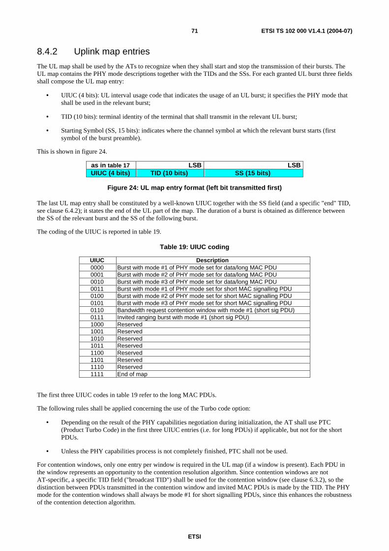
ETSI
ETSI TS 102 000 V1.4.1 (2004-07) 71
8.4.2 Uplink map entries
The UL map shall be used by the ATs to recognize when they shall start and stop the transmission of their bursts. The UL map contains the PHY mode descriptions together with the TIDs and the SSs. For each granted UL burst three fields shall compose the UL map entry:
• UIUC (4 bits): UL interval usage code that indicates the usage of an UL burst; it specifies the PHY mode that shall be used in the relevant burst;
• TID (10 bits): terminal identity of the terminal that shall transmit in the relevant UL burst;
• Starting Symbol (SS, 15 bits): indicates where the channel symbol at which the relevant burst starts (first symbol of the burst preamble).
This is shown in figure 24.
as in table 17 LSB LSB UIUC (4 bits) TID (10 bits) SS (15 bits)
Figure 24: UL map entry format (left bit transmitted first)
The last UL map entry shall be constituted by a well-known UIUC together with the SS field (and a specific "end" TID, see clause 6.4.2); it states the end of the UL part of the map. The duration of a burst is obtained as difference between the SS of the relevant burst and the SS of the following burst.
The coding of the UIUC is reported in table 19.
Table 19: UIUC coding
UIUC Description 0000 Burst with mode #1 of PHY mode set for data/long MAC PDU 0001 Burst with mode #2 of PHY mode set for data/long MAC PDU 0010 Burst with mode #3 of PHY mode set for data/long MAC PDU 0011 Burst with mode #1 of PHY mode set for short MAC signalling PDU 0100 Burst with mode #2 of PHY mode set for short MAC signalling PDU 0101 Burst with mode #3 of PHY mode set for short MAC signalling PDU 0110 Bandwidth request contention window with mode #1 (short sig PDU) 0111 Invited ranging burst with mode #1 (short sig PDU) 1000 Reserved 1001 Reserved 1010 Reserved 1011 Reserved 1100 Reserved 1101 Reserved 1110 Reserved 1111 End of map
The first three UIUC codes in table 19 refer to the long MAC PDUs.
The following rules shall be applied concerning the use of the Turbo code option:
• Depending on the result of the PHY capabilities negotiation during initialization, the AT shall use PTC (Product Turbo Code) in the first three UIUC entries (i.e. for long PDUs) if applicable, but not for the short PDUs.
• Unless the PHY capabilities process is not completely finished, PTC shall not be used.
For contention windows, only one entry per window is required in the UL map (if a window is present). Each PDU in the window represents an opportunity to the contention resolution algorithm. Since contention windows are not AT-specific, a specific TID field ("broadcast TID") shall be used for the contention window (see clause 6.3.2), so the distinction between PDUs transmitted in the contention window and invited MAC PDUs is made by the TID. The PHY mode for the contention windows shall always be mode #1 for short signalling PDUs, since this enhances the robustness of the contention detection algorithm.
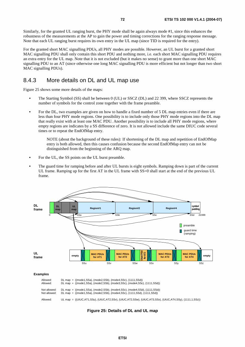
ETSI
ETSI TS 102 000 V1.4.1 (2004-07) 72
Similarly, for the granted UL ranging burst, the PHY mode shall be again always mode #1, since this enhances the robustness of the measurements at the AP to gain the power and timing corrections for the ranging response message. Note that each UL ranging burst requires its own entry in the UL map (since TID is required for the entry).
For the granted short MAC signalling PDUs, all PHY modes are possible. However, an UL burst for a granted short MAC signalling PDU shall only contain this short PDU and nothing more, i.e. each short MAC signalling PDU requires an extra entry for the UL map. Note that it is not excluded (but it makes no sense) to grant more than one short MAC signalling PDU to an AT (since otherwise one long MAC signalling PDU is more efficient but not longer than two short MAC signalling PDUs).
8.4.3 More details on DL and UL map use
Figure 25 shows some more details of the maps:
• The Starting Symbol (SS) shall be between 0 (UL) or SSCZ (DL) and 22 399, where SSCZ represents the number of symbols for the control zone together with the frame preamble.
• For the DL, two examples are given on how to handle a fixed number of 5 DL map entries even if there are less than four PHY mode regions. One possibility is to include only those PHY mode regions into the DL map that really exist with at least one MAC PDU. Another possibility is to include all PHY mode regions, where empty regions are indicates by a SS difference of zero. It is not allowed include the same DIUC code several times or to repeat the EndOfMap entry.
NOTE (about the background of these rules): If shortening of the DL map and repetition of EndOfMap entry is both allowed, then this causes confusion because the second EndOfMap entry can not be distinguished from the beginning of the ARQ map.
• For the UL, the SS points on the UL burst preamble.
• The guard time for ramping before and after UL bursts is eight symbols. Ramping down is part of the current UL frame. Ramping up for the first AT in the UL frame with SS=0 shall start at the end of the previous UL frame.
emptyMAC PDUs
for AT2
SSv SSw SSx SSy SSz
0 SSa SSb SSc SSd 22399
DLmap
ULmap Region#1 Region#2 Region#4
symbolpadding
DLframe
ULframe
preamble
guard time(ramping)
Examples
Allowed: DL map = ((mode1,SSa), (mode2,SSb), (mode4,SSc), (1111,SSd))Allowed: DL map = ((mode1,SSa), (mode2,SSb), (mode3,SSc), (mode4,SSc), (1111,SSd))
Not allowed: DL map = ((mode1,SSa), (mode2,SSb), (mode4,SSc), (mode4,SSd), (1111,SSd))Not allowed: DL map = ((mode1,SSa), (mode2,SSb), (mode4,SSc), (1111,SSd), (1111,SSd))
Allowed: UL map = ((UIUC,AT1,SSu), (UIUC,AT2,SSv), (UIUC,AT2,SSw), (UIUC,AT3,SSx), (UIUC,AT4,SSy), (1111,1,SSz))
MAC PDUsfor AT1empty
SSu
Shor
t PDU
for A
T2 MAC PDUsfor AT4
MAC PDUsfor AT3
Figure 25: Details of DL and UL map
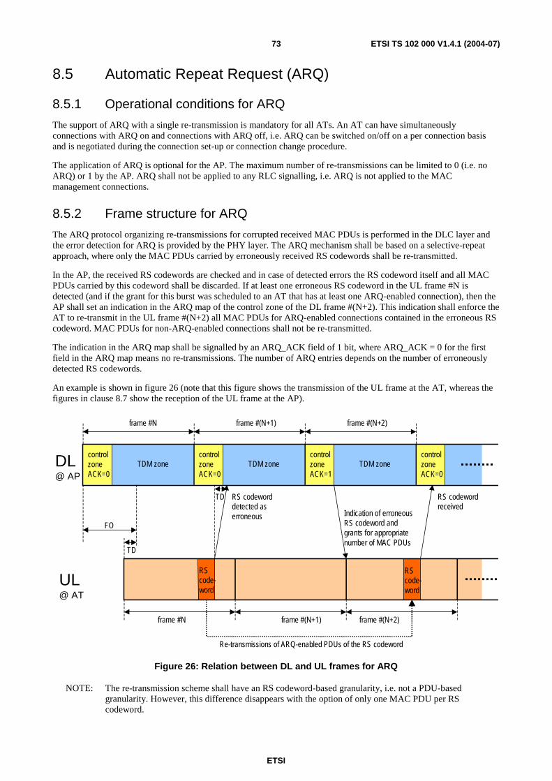
ETSI
ETSI TS 102 000 V1.4.1 (2004-07) 73
8.5 Automatic Repeat Request (ARQ)
8.5.1 Operational conditions for ARQ
The support of ARQ with a single re-transmission is mandatory for all ATs. An AT can have simultaneously connections with ARQ on and connections with ARQ off, i.e. ARQ can be switched on/off on a per connection basis and is negotiated during the connection set-up or connection change procedure.
The application of ARQ is optional for the AP. The maximum number of re-transmissions can be limited to 0 (i.e. no ARQ) or 1 by the AP. ARQ shall not be applied to any RLC signalling, i.e. ARQ is not applied to the MAC management connections.
8.5.2 Frame structure for ARQ
The ARQ protocol organizing re-transmissions for corrupted received MAC PDUs is performed in the DLC layer and the error detection for ARQ is provided by the PHY layer. The ARQ mechanism shall be based on a selective-repeat approach, where only the MAC PDUs carried by erroneously received RS codewords shall be re-transmitted.
In the AP, the received RS codewords are checked and in case of detected errors the RS codeword itself and all MAC PDUs carried by this codeword shall be discarded. If at least one erroneous RS codeword in the UL frame #N is detected (and if the grant for this burst was scheduled to an AT that has at least one ARQ-enabled connection), then the AP shall set an indication in the ARQ map of the control zone of the DL frame #(N+2). This indication shall enforce the AT to re-transmit in the UL frame #(N+2) all MAC PDUs for ARQ-enabled connections contained in the erroneous RS codeword. MAC PDUs for non-ARQ-enabled connections shall not be re-transmitted.
The indication in the ARQ map shall be signalled by an ARQ_ACK field of 1 bit, where ARQ_ACK = 0 for the first field in the ARQ map means no re-transmissions. The number of ARQ entries depends on the number of erroneously detected RS codewords.
An example is shown in figure 26 (note that this figure shows the transmission of the UL frame at the AT, whereas the figures in clause 8.7 show the reception of the UL frame at the AP).
frame #N frame #(N+1) frame #(N+2)
controlzoneACK=0
controlzoneACK=0
controlzoneACK=1
TDM zone TDM zone TDM zone
RScode-word
RS codeworddetected aserroneous
frame #N frame #(N+1) frame #(N+2)
Indication of erroneousRS codeword andgrants for appropriatenumber of MAC PDUs
controlzoneACK=0
RS codewordreceived
Re-transmissions of ARQ-enabled PDUs of the RS codeword
TD
DL@ AP
UL@ AT
TD
RScode-word
FO
Figure 26: Relation between DL and UL frames for ARQ
NOTE: The re-transmission scheme shall have an RS codeword-based granularity, i.e. not a PDU-based granularity. However, this difference disappears with the option of only one MAC PDU per RS codeword.
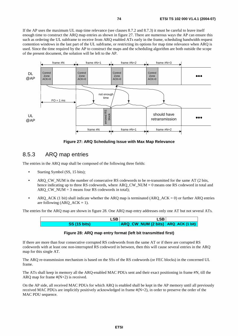
ETSI
ETSI TS 102 000 V1.4.1 (2004-07) 74
If the AP uses the maximum UL map time relevance (see clauses 8.7.2 and 8.7.3) it must be careful to leave itself enough time to construct the ARQ map entries as shown in figure 27. There are numerous ways the AP can ensure this such as ordering the UL subframe to receive from ARQ enabled ATs early in the frame, scheduling bandwidth request contention windows in the last part of the UL subframe, or restricting its options for map time relevance when ARQ is used. Since the time required by the AP to construct the maps and the scheduling algorithm are both outside the scope of the present document, the solution will be left to the AP.
should haveretransmission
ControlZone
ACK=0
ControlZone
ACK=0
ControlZone
ACK=0
ControlZone
ACK=0
FO = 1 ms
DL@AP
UL@AP
frame #N frame #N+3frame #N+2frame #N+1
erro
red
RS
bloc
k
not enoughtime
frame #N frame #N+2frame #N+1
Figure 27: ARQ Scheduling Issue with Max Map Relevance
8.5.3 ARQ map entries
The entries in the ARQ map shall be composed of the following three fields:
• Starting Symbol (SS, 15 bits);
• ARQ_CW_NUM is the number of consecutive RS codewords to be re-transmitted for the same AT (2 bits, hence indicating up to three RS codewords, where ARQ_CW_NUM = 0 means one RS codeword in total and ARQ_CW_NUM = 3 means four RS codewords in total);
• ARQ_ACK (1 bit) shall indicate whether the ARQ map is terminated (ARQ_ACK = 0) or further ARQ entries are following (ARQ_ACK = 1).
The entries for the ARQ map are shown in figure 28. One ARQ map entry addresses only one AT but not several ATs.
LSB LSB SS (15 bits) ARQ_CW_NUM (2 bits) ARQ_ACK (1 bit)
Figure 28: ARQ map entry format (left bit transmitted first)
If there are more than four consecutive corrupted RS codewords from the same AT or if there are corrupted RS codewords with at least one non-interrupted RS codeword in between, then this will cause several entries in the ARQ map for this single AT.
The ARQ re-transmission mechanism is based on the SSs of the RS codewords (or FEC blocks) in the concerned UL frame.
The ATs shall keep in memory all the ARQ-enabled MAC PDUs sent and their exact positioning in frame #N, till the ARQ map for frame #(N+2) is received.
On the AP side, all received MAC PDUs for which ARQ is enabled shall be kept in the AP memory until all previously received MAC PDUs are implicitly positively acknowledged in frame #(N+2), in order to preserve the order of the MAC PDU sequence.
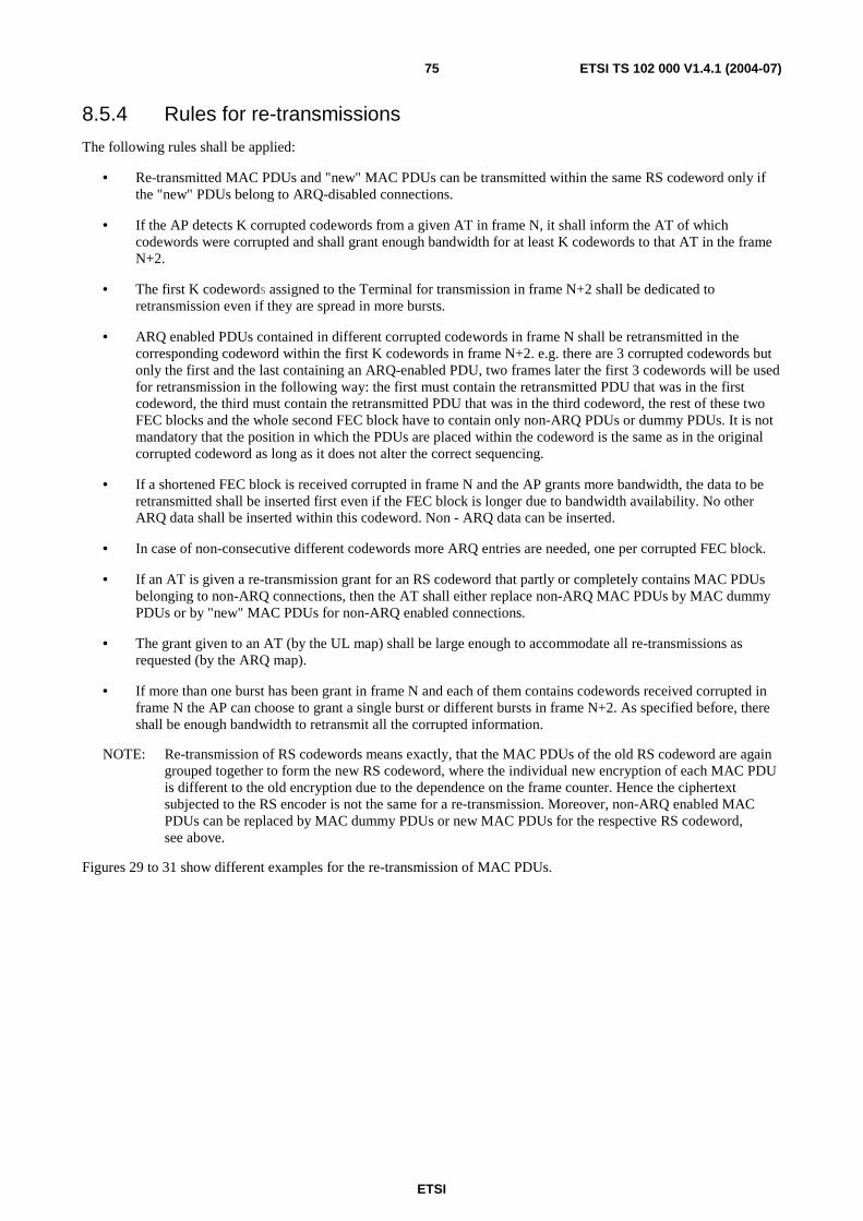
ETSI
ETSI TS 102 000 V1.4.1 (2004-07) 75
8.5.4 Rules for re-transmissions
The following rules shall be applied:
• Re-transmitted MAC PDUs and "new" MAC PDUs can be transmitted within the same RS codeword only if the "new" PDUs belong to ARQ-disabled connections.
• If the AP detects K corrupted codewords from a given AT in frame N, it shall inform the AT of which codewords were corrupted and shall grant enough bandwidth for at least K codewords to that AT in the frame N+2.
• The first K codewords assigned to the Terminal for transmission in frame N+2 shall be dedicated to retransmission even if they are spread in more bursts.
• ARQ enabled PDUs contained in different corrupted codewords in frame N shall be retransmitted in the corresponding codeword within the first K codewords in frame N+2. e.g. there are 3 corrupted codewords but only the first and the last containing an ARQ-enabled PDU, two frames later the first 3 codewords will be used for retransmission in the following way: the first must contain the retransmitted PDU that was in the first codeword, the third must contain the retransmitted PDU that was in the third codeword, the rest of these two FEC blocks and the whole second FEC block have to contain only non-ARQ PDUs or dummy PDUs. It is not mandatory that the position in which the PDUs are placed within the codeword is the same as in the original corrupted codeword as long as it does not alter the correct sequencing.
• If a shortened FEC block is received corrupted in frame N and the AP grants more bandwidth, the data to be retransmitted shall be inserted first even if the FEC block is longer due to bandwidth availability. No other ARQ data shall be inserted within this codeword. Non - ARQ data can be inserted.
• In case of non-consecutive different codewords more ARQ entries are needed, one per corrupted FEC block.
• If an AT is given a re-transmission grant for an RS codeword that partly or completely contains MAC PDUs belonging to non-ARQ connections, then the AT shall either replace non-ARQ MAC PDUs by MAC dummy PDUs or by "new" MAC PDUs for non-ARQ enabled connections.
• The grant given to an AT (by the UL map) shall be large enough to accommodate all re-transmissions as requested (by the ARQ map).
• If more than one burst has been grant in frame N and each of them contains codewords received corrupted in frame N the AP can choose to grant a single burst or different bursts in frame N+2. As specified before, there shall be enough bandwidth to retransmit all the corrupted information.
NOTE: Re-transmission of RS codewords means exactly, that the MAC PDUs of the old RS codeword are again grouped together to form the new RS codeword, where the individual new encryption of each MAC PDU is different to the old encryption due to the dependence on the frame counter. Hence the ciphertext subjected to the RS encoder is not the same for a re-transmission. Moreover, non-ARQ enabled MAC PDUs can be replaced by MAC dummy PDUs or new MAC PDUs for the respective RS codeword, see above.
Figures 29 to 31 show different examples for the re-transmission of MAC PDUs.
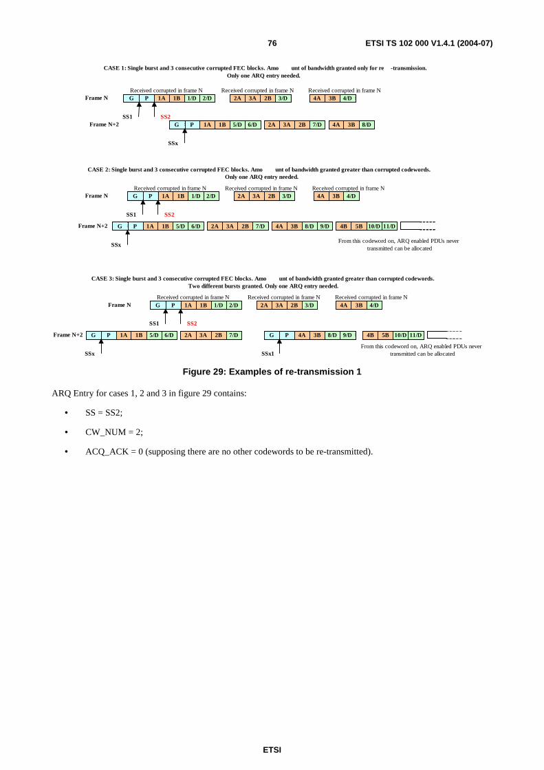
ETSI
ETSI TS 102 000 V1.4.1 (2004-07) 76
2A 3A 2B 3/D 2A 3A 2B 3/D 4A 3B 4/D 4A 3B 4/D 1A 1B 1/D 2/D P G 1A 1B 1/D 2/D P G
SS1
CASE 1: Single burst and 3 consecutive corrupted FEC blocks. Amo unt of bandwidth granted only for re - transmission. Only one ARQ entry needed.
Received corrupted in frame N
1A 1B 5/D 6/D P G 1A 1B 5/D 6/D P G 2A 3A 2B 7/D 2A 3A 2B 7/D 4A 3B 8/D 4A 3B 8/D
SSx
SS2
Received corrupted in frame N Received corrupted in frame N
CASE 2: Single burst and 3 consecutive corrupted FEC blocks. Amo unt of bandwidth granted greater than corrupted codewords. Only one ARQ entry needed.
1A 1B 5/D 6/D P G 1A 1B 5/D 6/D P G 2A 3A 2B 7/D 2A 3A 2B 7/D 9/D 4A 3B 8/D 9/D 4A 3B 8/D 4A 3B 8/D
SSx
SS2
2A 3A 2B 3/D 2A 3A 2B 3/D 4A 3B 4/D 4A 3B 4/D 1A 1B 1/D 2/D P G 1A 1B 1/D 2/D P G
SS1
Received corrupted in frame N Received corrupted in frame N Received corrupted in frame N
4B 5B 10/D 11/D 4B 5B 10/D 11/D
Frame N
Frame N
Frame N+2
Frame N+2
CASE 3: Single burst and 3 consecutive corrupted FEC blocks. Amo unt of bandwidth granted greater than corrupted codewords. Two different bursts granted. Only one ARQ entry needed.
1A 1B 5/D 6/D P G 1A 1B 5/D 6/D P G 2A 3A 2B 7/D 2A 3A 2B 7/D
SSx
SS2
2A 3A 2B 3/D 2A 3A 2B 3/D 4A 3B 4/D 4A 3B 4/D 1A 1B 1/D 2/D P G 1A 1B 1/D 2/D P G
SS1
Received corrupted in frame N Received corrupted in frame N Received corrupted in frame N
4B 5B 10/D 11/D 4B 5B 10/D 11/D
Frame N
Frame N+2 9/D 4A 3B 8/D P G 9/D 4A 3B 8/D 9/D 4A 3B 8/D 4A 3B 8/D P G
SSx1
From this codeword on, ARQ enabled PDUs never transmitted can be allocated
From this codeword on, ARQ enabled PDUs never transmitted can be allocated
Figure 29: Examples of re-transmission 1
ARQ Entry for cases 1, 2 and 3 in figure 29 contains:
• SS = SS2;
• CW_NUM = 2;
• ACQ_ACK = 0 (supposing there are no other codewords to be re-transmitted).
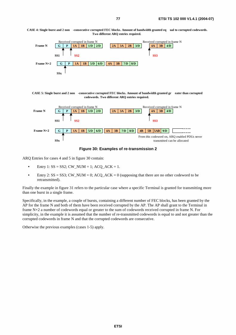
ETSI
ETSI TS 102 000 V1.4.1 (2004-07) 77
8/D
CASE 4: Single burst and 2 non - consecutive corrupted FEC blocks. Amount of bandwidth granted eq ual to corrupted codewords. Two different ARQ entries required.
2A 3A 2B 3/D 2A 3A 2B 3/D 4A 3B 4/D 4A 3B 4/D 1A 1B 1/D 2/D P G 1A 1B 1/D 2/D P G
SS1
1A 1B 5/D 6/D P G 1A 1B 5/D 6/D P G
SSx
SS2
Received corrupted in frame N Received corrupted in frame N
4A 3B 7/D 4A 3B 7/D
Frame N
2A 3A 2B 3/D 2A 3A 2B 3/D 4A 3B 4/D 4A 3B 4/D 1A 1B 1/D 2/D P G 1A 1B 1/D 2/D P G
SS1
Received corrupted in frame N Received corrupted in frame N
CASE 5: Single burst and 2 non - consecutive corrupted FEC blocks. Amount of bandwidth granted gr eater than corrupted codewords. Two different ARQ entries required.
1A 1B 5/D 6/D P G 1A 1B 5/D 6/D P G
SSx
SS2
8/D 4A 3B 7/D 8/D 4A 3B 7/D 4A 3B 7/D 4B 5B 5AB 9/D 4B 5B 5AB 9/D
Frame N
Frame N+2
Frame N+2
SS3
SS3
From this codeword on, ARQ enabled PDUs never transmitted can be allocated
Figure 30: Examples of re-transmission 2
ARQ Entries for cases 4 and 5 in figure 30 contain:
• Entry 1: SS = SS2; CW_NUM = 1; ACQ_ACK = 1.
• Entry 2: SS = SS3; CW_NUM = 0; ACQ_ACK = 0 (supposing that there are no other codeword to be retransmitted).
Finally the example in figure 31 refers to the particular case where a specific Terminal is granted for transmitting more than one burst in a single frame.
Specifically, in the example, a couple of bursts, containing a different number of FEC blocks, has been granted by the AP for the frame N and both of them have been received corrupted by the AP. The AP shall grant to the Terminal in frame N+2 a number of codewords equal or greater to the sum of codewords received corrupted in frame N. For simplicity, in the example it is assumed that the number of re-transmitted codewords is equal to and not greater than the corrupted codewords in frame N and that the corrupted codewords are consecutive.
Otherwise the previous examples (cases 1-5) apply.
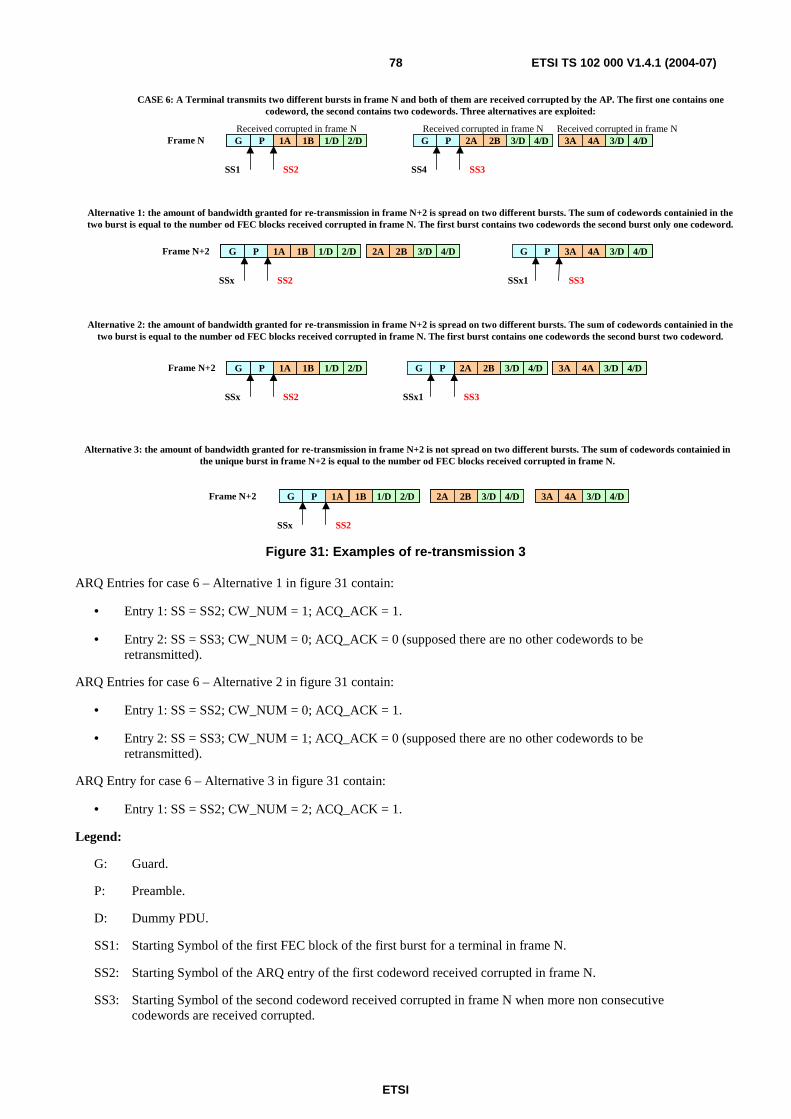
ETSI
ETSI TS 102 000 V1.4.1 (2004-07) 78
CASE 6: A Terminal transmits two different bursts in frame N and both of them are received corrupted by the AP. The first one contains one codeword, the second contains two codewords. Three alternatives are exploited:
2A 2B 3/D 4/DPG 2A 2B 3/D 4/DPG
SS4
Received corrupted in frame N1A 1B 1/D 2/DPG 1A 1B 1/D 2/DPG
SS1
Received corrupted in frame NFrame N
2A 2B 3/D 4/D2A 2B 3/D 4/D PG
SSx1
SS3
1A 1B 1/D 2/DPG 1A 1B 1/D 2/DPG
SSx
SS2
Frame N+2
1A 1B 1/D 2/DPG 1A 1B 1/D 2/DPG
SSx
Frame N+2 2A 2B 4/D3/D2A 2B 4/D3/D
Alternative 3: the amount of bandwidth granted for re-transmission in frame N+2 is not spread on two different bursts. The sum of codewords containied in the unique burst in frame N+2 is equal to the number od FEC blocks received corrupted in frame N.
3A 4A 3/D 4/D3A 4A 3/D 4/D
3A 4A 3/D 4/D3A 4A 3/D 4/D
Alternative 1: the amount of bandwidth granted for re-transmission in frame N+2 is spread on two different bursts. The sum of codewords containied in the two burst is equal to the number od FEC blocks received corrupted in frame N. The first burst contains two codewords the second burst only one codeword.
2A 2B 3/D 4/D2A 2B 3/D 4/DPG
SSx1
1A 1B 1/D 2/DPG 1A 1B 1/D 2/DPG
SSx
Frame N+2 3A 4A 3/D 4/D3A 4A 3/D 4/D
Alternative 2: the amount of bandwidth granted for re-transmission in frame N+2 is spread on two different bursts. The sum of codewords containied in the two burst is equal to the number od FEC blocks received corrupted in frame N. The first burst contains one codewords the second burst two codeword.
3A 4A 3/D 4/D3A 4A 3/D 4/D
SS2
SS2
SS2
SS3
SS3
Received corrupted in frame N
Figure 31: Examples of re-transmission 3
ARQ Entries for case 6 – Alternative 1 in figure 31 contain:
• Entry 1: SS = SS2; CW_NUM = 1; ACQ_ACK = 1.
• Entry 2: SS = SS3; CW_NUM = 0; ACQ_ACK = 0 (supposed there are no other codewords to be retransmitted).
ARQ Entries for case 6 – Alternative 2 in figure 31 contain:
• Entry 1: SS = SS2; CW_NUM = 0; ACQ_ACK = 1.
• Entry 2: SS = SS3; CW_NUM = 1; ACQ_ACK = 0 (supposed there are no other codewords to be retransmitted).
ARQ Entry for case 6 – Alternative 3 in figure 31 contain:
• Entry 1: SS = SS2; CW_NUM = 2; ACQ_ACK = 1.
Legend:
G: Guard.
P: Preamble.
D: Dummy PDU.
SS1: Starting Symbol of the first FEC block of the first burst for a terminal in frame N.
SS2: Starting Symbol of the ARQ entry of the first codeword received corrupted in frame N.
SS3: Starting Symbol of the second codeword received corrupted in frame N when more non consecutive codewords are received corrupted.
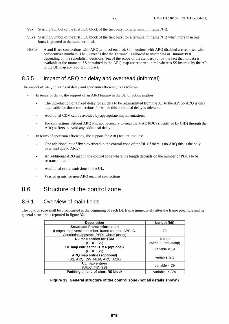
ETSI
ETSI TS 102 000 V1.4.1 (2004-07) 79
SSx: Starting Symbol of the first FEC block of the first burst for a terminal in frame N+2.
SSx1: Starting Symbol of the first FEC block of the first burst for a terminal in frame N+2 when more than one burts is granted to the same terminal.
NOTE: A and B are connections with ARQ protocol enabled. Connections with ARQ disabled are reported with consecutives numbers. The /D means that the Terminal is allowed to insert data or Dummy PDU depending on the schedulism decisions (out of the scope of the standard) or by the fact that no data is available at the moment. SS contained in the ARQ map are reported in red whereas SS inserted by the AP in the UL map are reported in black.
8.5.5 Impact of ARQ on delay and overhead (informal)
The impact of ARQ in terms of delay and spectrum efficiency is as follows:
• In terms of delay, the support of an ARQ feature in the UL direction implies:
- The introduction of a fixed delay for all data to be retransmitted from the AT to the AP. So ARQ is only applicable for those connections for which this additional delay is tolerable.
- Additional CDV can be avoided by appropriate implementations.
- For connections without ARQ it is not necessary to send the MAC PDUs (identified by CID) through the ARQ buffers to avoid any additional delay.
• In terms of spectrum efficiency, the support for ARQ feature implies:
- One additional bit of fixed overhead in the control zone of the DL (if there is no ARQ this is the only overhead due to ARQ).
- An additional ARQ map in the control zone where the length depends on the number of PDUs to be re-transmitted.
- Additional re-transmissions in the UL.
- Wasted grants for non-ARQ enabled connections.
8.6 Structure of the control zone
8.6.1 Overview of main fields
The control zone shall be broadcasted at the beginning of each DL frame immediately after the frame preamble and its general structure is reported in figure 32.
Description Length [bit] Broadcast Frame Information
(Length, map version number, frame counter, APC-ID, ContentionOppsAck, PSDI, ClockQuality)
72
DL map entries for TDM (DIUC, SS)
4 × 19 (without EndOfMap)
DL map entries for TDMA (optional) (DIUC, SS) variable × 19
ARQ map entries (optional) (SS, ARQ_CW_NUM, ARQ_ACK) variable, ≥ 1
UL map entries (UIUC, TID, SS) variable × 29
Padding till end of short RS block variable, ≤ 239
Figure 32: General structure of the control zone (not all details shown)
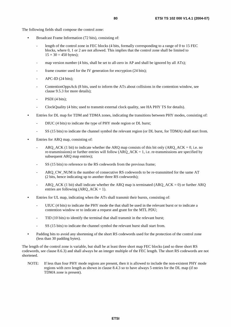
ETSI
ETSI TS 102 000 V1.4.1 (2004-07) 80
The following fields shall compose the control zone:
• Broadcast Frame Information (72 bits), consisting of:
- length of the control zone in FEC blocks (4 bits, formally corresponding to a range of 0 to 15 FEC blocks, where 0, 1 or 2 are not allowed. This implies that the control zone shall be limited to 15 × 30 = 450 bytes);
- map version number (4 bits, shall be set to all-zero in AP and shall be ignored by all ATs);
- frame counter used for the IV generation for encryption (24 bits);
- APC-ID (24 bits);
- ContentionOppsAck (8 bits, used to inform the ATs about collisions in the contention window, see clause 9.5.3 for more details);
- PSDI (4 bits);
- ClockQuality (4 bits; used to transmit external clock quality, see HA PHY TS for details).
• Entries for DL map for TDM and TDMA zones, indicating the transitions between PHY modes, consisting of:
- DIUC (4 bits) to indicate the type of PHY mode region or DL burst;
- SS (15 bits) to indicate the channel symbol the relevant region (or DL burst, for TDMA) shall start from.
• Entries for ARQ map, consisting of:
- ARQ_ACK (1 bit) to indicate whether the ARQ map consists of this bit only (ARQ_ACK = 0, i.e. no re-transmissions) or further entries will follow (ARQ_ACK = 1, i.e. re-transmissions are specified by subsequent ARQ map entries);
- SS (15 bits) to reference to the RS codewords from the previous frame;
- ARQ_CW_NUM is the number of consecutive RS codewords to be re-transmitted for the same AT (2 bits, hence indicating up to another three RS codewords);
- ARQ_ACK (1 bit) shall indicate whether the ARQ map is terminated (ARQ_ACK = 0) or further ARQ entries are following (ARQ_ACK = 1).
• Entries for UL map, indicating when the ATs shall transmit their bursts, consisting of:
- UIUC (4 bits) to indicate the PHY mode the that shall be used in the relevant burst or to indicate a contention window or to indicate a request and grant for the MTL PDU;
- TID (10 bits) to identify the terminal that shall transmit in the relevant burst;
- SS (15 bits) to indicate the channel symbol the relevant burst shall start from.
• Padding bits to avoid any shortening of the short RS codewords used for the protection of the control zone (less than 30 padding bytes).
The length of the control zone is variable, but shall be at least three short map FEC blocks (and so three short RS codewords, see clause 8.6.3) and shall always be an integer multiple of the FEC length. The short RS codewords are not shortened.
NOTE: If less than four PHY mode regions are present, then it is allowed to include the non-existent PHY mode regions with zero length as shown in clause 8.4.3 so to have always 5 entries for the DL map (if no TDMA zone is present).
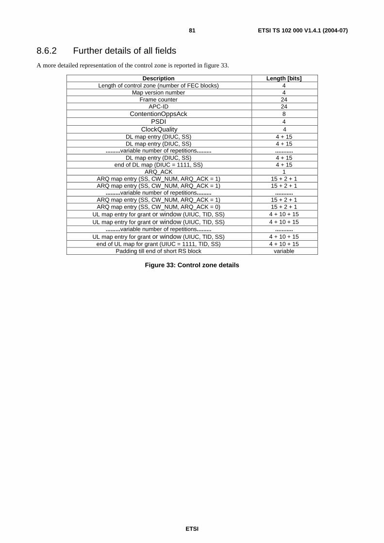
ETSI
ETSI TS 102 000 V1.4.1 (2004-07) 81
8.6.2 Further details of all fields
A more detailed representation of the control zone is reported in figure 33.
Description Length [bits] Length of control zone (number of FEC blocks) 4
Map version number 4 Frame counter 24
APC-ID 24 ContentionOppsAck 8
PSDI 4 ClockQuality 4
DL map entry (DIUC, SS) 4 + 15 DL map entry (DIUC, SS) 4 + 15
.........variable number of repetitions......... ........... DL map entry (DIUC, SS) 4 + 15
end of DL map (DIUC = 1111, SS) 4 + 15 ARQ_ACK 1
ARQ map entry (SS, CW_NUM, ARQ_ACK = 1) 15 + 2 + 1 ARQ map entry (SS, CW_NUM, ARQ_ACK = 1) 15 + 2 + 1
.........variable number of repetitions......... ........... ARQ map entry (SS, CW_NUM, ARQ_ACK = 1) 15 + 2 + 1 ARQ map entry (SS, CW_NUM, ARQ_ACK = 0) 15 + 2 + 1
UL map entry for grant or window (UIUC, TID, SS) 4 + 10 + 15 UL map entry for grant or window (UIUC, TID, SS) 4 + 10 + 15
.........variable number of repetitions......... ........... UL map entry for grant or window (UIUC, TID, SS) 4 + 10 + 15
end of UL map for grant (UIUC = 1111, TID, SS) 4 + 10 + 15 Padding till end of short RS block variable
Figure 33: Control zone details
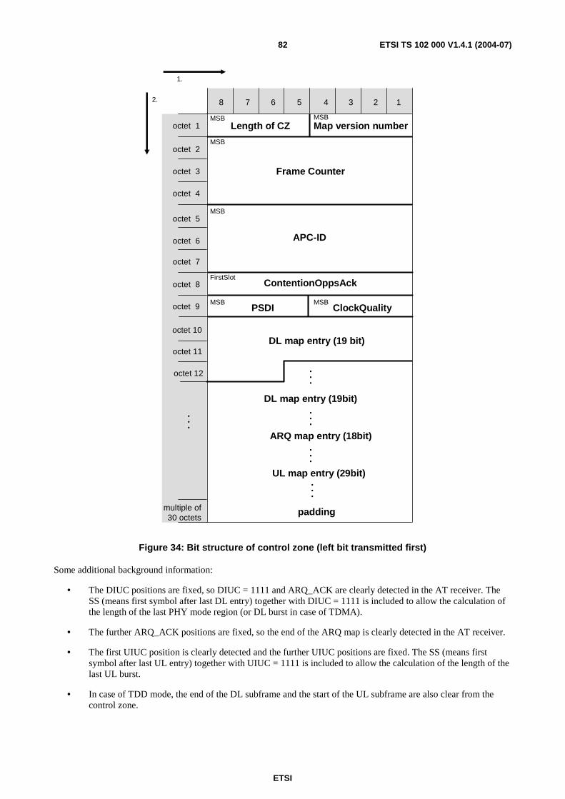
ETSI
ETSI TS 102 000 V1.4.1 (2004-07) 82
UL map entry (29bit)
8 7 6 5 4 3 2
octet 8
octet 9
octet 10
multiple of 30 octets
Length of CZ
1
Frame Counter
APC-ID
PSDI
Map version number
DL map entry (19 bit)
DL map entry (19bit)
ARQ map entry (18bit)
padding
.
.
.
..
.
.
..
..
.
..
.
octet 7
octet 6
octet 5
octet 4
octet 3
octet 2
octet 1
octet 11
ContentionOppsAckFirstSlot
MSB MSB
MSB
MSB
MSB
1.
2.
ClockQualityMSB
octet 12
Figure 34: Bit structure of control zone (left bit transmitted first)
Some additional background information:
• The DIUC positions are fixed, so DIUC = 1111 and ARQ_ACK are clearly detected in the AT receiver. The SS (means first symbol after last DL entry) together with DIUC = 1111 is included to allow the calculation of the length of the last PHY mode region (or DL burst in case of TDMA).
• The further ARQ_ACK positions are fixed, so the end of the ARQ map is clearly detected in the AT receiver.
• The first UIUC position is clearly detected and the further UIUC positions are fixed. The SS (means first symbol after last UL entry) together with UIUC = 1111 is included to allow the calculation of the length of the last UL burst.
• In case of TDD mode, the end of the DL subframe and the start of the UL subframe are also clear from the control zone.
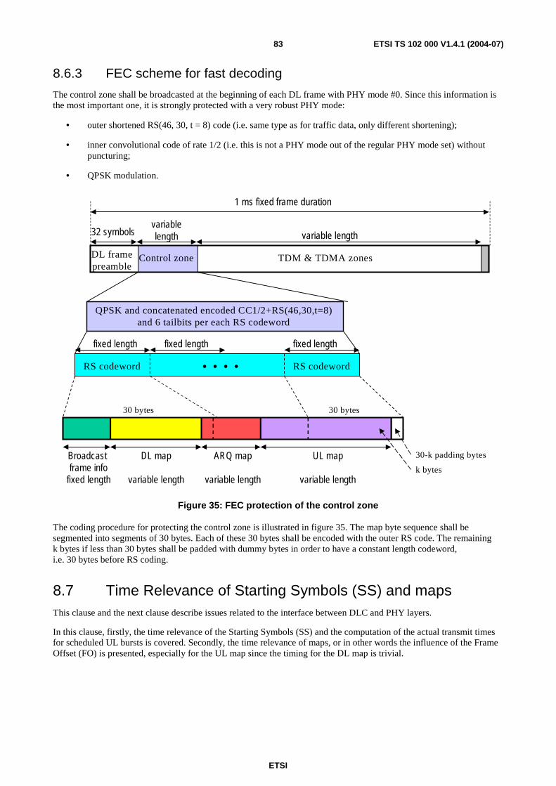
ETSI
ETSI TS 102 000 V1.4.1 (2004-07) 83
8.6.3 FEC scheme for fast decoding
The control zone shall be broadcasted at the beginning of each DL frame with PHY mode #0. Since this information is the most important one, it is strongly protected with a very robust PHY mode:
• outer shortened RS(46, 30, t = 8) code (i.e. same type as for traffic data, only different shortening);
• inner convolutional code of rate 1/2 (i.e. this is not a PHY mode out of the regular PHY mode set) without puncturing;
• QPSK modulation.
DL framepreamble
1 ms fixed frame duration
Control zone TDM & TDMA zones
variable length
RS codeword
QPSK and concatenated encoded CC1/2+RS(46,30,t=8) and 6 tailbits per each RS codeword
DL map
variable length
UL map
variable length
variablelength32 symbols
fixed length fixed length fixed length
. . . .
k bytes
Broadcast frame info
fixed length
ARQ map
variable length
30 bytes
30-k padding bytes
30 bytes
RS codeword
Figure 35: FEC protection of the control zone
The coding procedure for protecting the control zone is illustrated in figure 35. The map byte sequence shall be segmented into segments of 30 bytes. Each of these 30 bytes shall be encoded with the outer RS code. The remaining k bytes if less than 30 bytes shall be padded with dummy bytes in order to have a constant length codeword, i.e. 30 bytes before RS coding.
8.7 Time Relevance of Starting Symbols (SS) and maps This clause and the next clause describe issues related to the interface between DLC and PHY layers.
In this clause, firstly, the time relevance of the Starting Symbols (SS) and the computation of the actual transmit times for scheduled UL bursts is covered. Secondly, the time relevance of maps, or in other words the influence of the Frame Offset (FO) is presented, especially for the UL map since the timing for the DL map is trivial.

ETSI
ETSI TS 102 000 V1.4.1 (2004-07) 84
8.7.1 Starting Symbols for UL bursts
The AT knows:
• the sector-specific Frame Offset (FO) from reading the GBI message; and
• its individual Transmission Delay (TD) or the Round Trip Delay (RTD) from the initialization phase (and updated by further AT-specific messages in the DL if required).
The RTD is simply the double of TD and EGT shall be equal or larger than the maximum of RTD (determined by the farthest AT in the sector).
The FO is chosen by the AP, however, usually the FO should be larger than the sum of the maximum length of the control zone plus the EGT plus the TP (Time for Processing), where TP denotes the time required in the AT to decode the UL map after complete reception of the control zone.
The calculation of the physical starting time (derived from the numbering of the received DL frame) for an UL burst from the Starting Symbol (SS) contained in the UL map entries is shown in figure 36.
frame duration
controlzone EGT TP
FO
DL frame transmitted at AP
UL frame received at AP
DL frame receivedat AT1
UL burst transmittedat AT1 within UL frame
TD TDFO-RTD
SS_AT1 SS_AT2
UL burstfrom AT1
UL burstfrom AT1
TD
frame duration
whereT1a=FO-RTD+SS_AT1T1b=FO-RTD+SS_AT2
T1a T1b
UL map:SS_AT1,SS_AT2,...
controlzone TP
UL map:SS_AT1,SS_AT2,...
Figure 36: Starting times for UL bursts
In figure 36, the terminal AT1 is assumed at the maximum distance from the AP for simplicity, so EGT = RTD. The UL map contains an entry for AT1 with the starting symbol SS_AT1. The next entry in the UL map contains a starting symbol SS_AT2 for another terminal AT2. The SS values refer to the numbering of the UL frame at the AP, where the range is determined by 0 ≤ SS ≤ 22 399 (note that the symbol rate is 22,4 MBaud and the frame duration is 1 ms).
The AT1 counts the symbols in the received DL frame, from 1 to 22 400. With regard to this counter, AT1 is allowed to transmit from T1a = FO−RTD + SS_AT1 till T1b = FO−RTD + SS_AT2.
NOTE 1: This follows from the specific case of SS_AT1 = 0 (which is immediately intelligible).
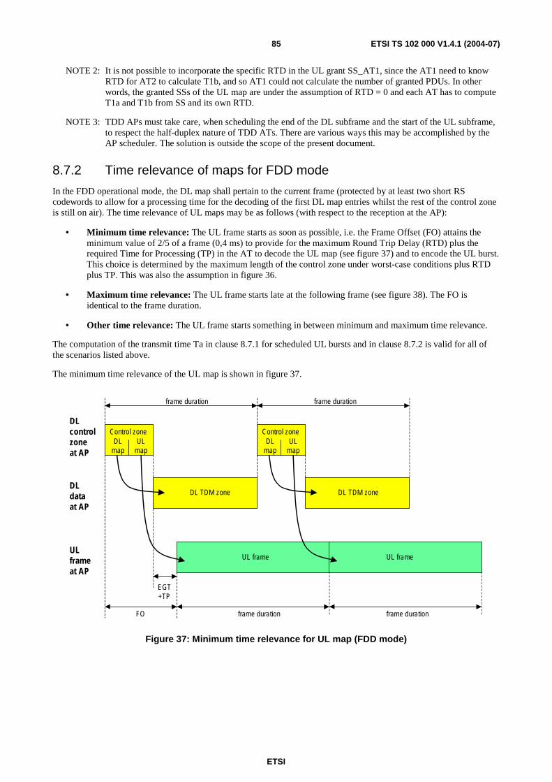
ETSI
ETSI TS 102 000 V1.4.1 (2004-07) 85
NOTE 2: It is not possible to incorporate the specific RTD in the UL grant SS_AT1, since the AT1 need to know RTD for AT2 to calculate T1b, and so AT1 could not calculate the number of granted PDUs. In other words, the granted SSs of the UL map are under the assumption of RTD = 0 and each AT has to compute T1a and T1b from SS and its own RTD.
NOTE 3: TDD APs must take care, when scheduling the end of the DL subframe and the start of the UL subframe, to respect the half-duplex nature of TDD ATs. There are various ways this may be accomplished by the AP scheduler. The solution is outside the scope of the present document.
8.7.2 Time relevance of maps for FDD mode
In the FDD operational mode, the DL map shall pertain to the current frame (protected by at least two short RS codewords to allow for a processing time for the decoding of the first DL map entries whilst the rest of the control zone is still on air). The time relevance of UL maps may be as follows (with respect to the reception at the AP):
• Minimum time relevance: The UL frame starts as soon as possible, i.e. the Frame Offset (FO) attains the minimum value of 2/5 of a frame (0,4 ms) to provide for the maximum Round Trip Delay (RTD) plus the required Time for Processing (TP) in the AT to decode the UL map (see figure 37) and to encode the UL burst. This choice is determined by the maximum length of the control zone under worst-case conditions plus RTD plus TP. This was also the assumption in figure 36.
• Maximum time relevance: The UL frame starts late at the following frame (see figure 38). The FO is identical to the frame duration.
• Other time relevance: The UL frame starts something in between minimum and maximum time relevance.
The computation of the transmit time Ta in clause 8.7.1 for scheduled UL bursts and in clause 8.7.2 is valid for all of the scenarios listed above.
The minimum time relevance of the UL map is shown in figure 37.
frame duration
DLcontrolzoneat AP
EGT+TP
frame duration
Control zoneUL
mapDL
map
Control zoneUL
mapDL
map
FO frame duration frame duration
UL frame UL frame
DL TDM zone DL TDM zoneDLdataat AP
ULframeat AP
Figure 37: Minimum time relevance for UL map (FDD mode)
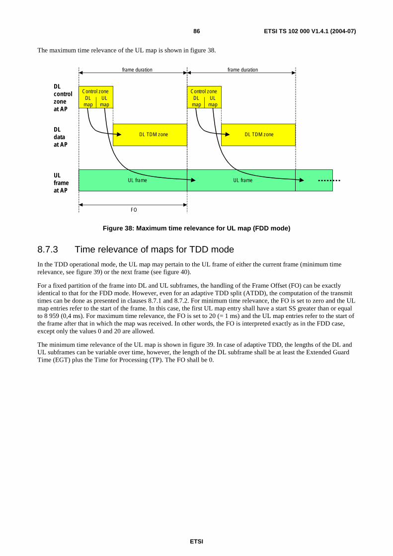
ETSI
ETSI TS 102 000 V1.4.1 (2004-07) 86
The maximum time relevance of the UL map is shown in figure 38.
frame duration
DLcontrolzoneat AP
frame duration
Control zoneUL
mapDL
map
Control zoneUL
mapDL
map
FO
UL frame UL frame
DL TDM zone DL TDM zoneDLdataat AP
ULframeat AP
Figure 38: Maximum time relevance for UL map (FDD mode)
8.7.3 Time relevance of maps for TDD mode
In the TDD operational mode, the UL map may pertain to the UL frame of either the current frame (minimum time relevance, see figure 39) or the next frame (see figure 40).
For a fixed partition of the frame into DL and UL subframes, the handling of the Frame Offset (FO) can be exactly identical to that for the FDD mode. However, even for an adaptive TDD split (ATDD), the computation of the transmit times can be done as presented in clauses 8.7.1 and 8.7.2. For minimum time relevance, the FO is set to zero and the UL map entries refer to the start of the frame. In this case, the first UL map entry shall have a start SS greater than or equal to 8 959 (0,4 ms). For maximum time relevance, the FO is set to 20 (= 1 ms) and the UL map entries refer to the start of the frame after that in which the map was received. In other words, the FO is interpreted exactly as in the FDD case, except only the values 0 and 20 are allowed.
The minimum time relevance of the UL map is shown in figure 39. In case of adaptive TDD, the lengths of the DL and UL subframes can be variable over time, however, the length of the DL subframe shall be at least the Extended Guard Time (EGT) plus the Time for Processing (TP). The FO shall be 0.
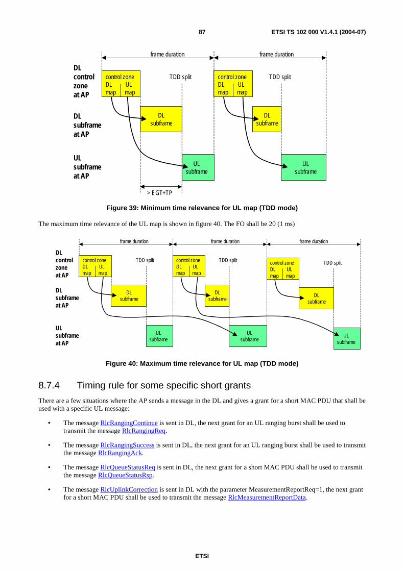
ETSI
ETSI TS 102 000 V1.4.1 (2004-07) 87
frame duration
> EGT+TP
control zoneDL ULmap map
control zoneDL ULmap map
DLsubframe
ULsubframe
DL control zoneat AP
DL subframeat AP
UL subframeat AP
frame duration
TDD split
DLsubframe
TDD split
ULsubframe
Figure 39: Minimum time relevance for UL map (TDD mode)
The maximum time relevance of the UL map is shown in figure 40. The FO shall be 20 (1 ms)
frame duration
control zoneDL ULmap map
DL control zoneat AP
DL subframeat AP
UL subframeat AP
frame duration
control zoneDL ULmap map
DLsubframe
ULsubframe
TDD split
DLsubframe
TDD split
ULsubframe
control zoneDL ULmap map
DLsubframe
ULsubframe
TDD split
frame duration
Figure 40: Maximum time relevance for UL map (TDD mode)
8.7.4 Timing rule for some specific short grants
There are a few situations where the AP sends a message in the DL and gives a grant for a short MAC PDU that shall be used with a specific UL message:
• The message RlcRangingContinue is sent in DL, the next grant for an UL ranging burst shall be used to transmit the message RlcRangingReq.
• The message RlcRangingSuccess is sent in DL, the next grant for an UL ranging burst shall be used to transmit the message RlcRangingAck.
• The message RlcQueueStatusReq is sent in DL, the next grant for a short MAC PDU shall be used to transmit the message RlcQueueStatusRsp.
• The message RlcUplinkCorrection is sent in DL with the parameter MeasurementReportReq=1, the next grant for a short MAC PDU shall be used to transmit the message RlcMeasurementReportData.
ETSI
ETSI TS 102 000 V1.4.1 (2004-07) 88
For all these cases, the following timing rule shall be applied: If the DL message is transmitted in frame #N, then the grant for the short burst (i.e. short MAC PDU or UL ranging burst) shall be given as follows:
• For RlcRangingContinue messages: At frame N+10 or later.
• For RlcRangingSuccess messages: At frame N+10 or later.
• For RlcQueueStatusReq messages: At frame N+1 or later.
• For RlcUplinkCorrection messages: At frame N+4 or later.
8.8 General Broadcast Information (GBI) message The GBI (General Broadcast Information) message RlcGeneralBroadcastInformation is a broadcast message containing general carrier-specific information that does not need to be transmitted in each frame (in contrast to the broadcast information contained in the control zone of each DL frame). The content of the GBI message can be grouped into several parts:
• General information about the carrier (and the network) related to operation modes, frame offset, message periods, structure of UL bursts, parameters for contention resolution and some other information fields.
• The PSD (PHY mode Set Descriptor) containing the C/(N+I) thresholds for all relevant sets of PHY modes (currently up to two) together with a PSD-specific PSDI (PSD Indicator). The PSDI is just a reference to the PSD. The description of the PHY mode includes the thresholds for up (channel improves) and down (channel is worse off) direction together with the respective changes of the transmit power that shall be applied during PHY mode switching.
Normally, only one set shall be described by the PSD. However, if a change from one PHY mode set to another PHY mode set shall be performed, then the new set shall be described by the PSD some time in advance, where a strict period is not required. The GBI message with the new PSD shall be broadcasted several times to guarantee that almost all ATs have received the information correctly.
The parameters carried in the PSD part are described in figure 41:
• 2n C/N thresholds (each threshold requires 8 bit prior to encoding); and
• 4(m-1) transmit power gaps (each gap requires 6 bit prior to encoding);
shall be transmitted for one PHY mode set, where n and m are the numbers of PHY modes for DL and UL direction, respectively.

ETSI
ETSI TS 102 000 V1.4.1 (2004-07) 89
PH Y m ode 4=n
PH Y m ode 3
PH Y m ode 2
PH Y m ode 1
PerformDL ATPC(optional)
C /(N +I) for D L
2nthresholds
TX power for UL(non-TC mode)
2(m-1) TX pow er corrections
PH Y m ode 3=m
PH Y m ode 2
PH Y m ode 1
2(m -1) TX power corrections
TX pow er for UL(TC mode)
Radio link quality
increasedecrease
U pgrade D ow ngrade
Figure 41: Parameters for PHY mode set description
The dynamic use of the C/(N+I) threshold pairs is specified in clause 11.3.4. The first (lower values) C/(N+I) threshold pair is only relevant if the optional DL ATPC is activated (see clause 11.3.6) but shall be always contained in the GBI message. The transmit power gaps for PTC are only relevant if at least one AT in the carrier uses the PTC option, but again these values shall be always contained in the GBI message.
The complete GBI message RlcGeneralBroadcastInformation is described with ASN1 in annex B. Note that normally only one PHY mode set is present, and two PHY mode sets are only present during the PHY mode set exchange phase (even in this case, the GBI message fits into one long MAC signalling PDU).
A change of PHY modes is performed as follows:
• A change from one to another PHY mode for a specific AT is part of the regular adaptive operation in DL and UL and is communicated by the DIUC and UIUC, respectively.
• A change from one to another PHY mode set for a sector is communicated by the corresponding PSDI in the control zone.
More details are specified in clause 11.4. Some rules for the PHY mode sets:
• PHY mode #1 is identical for all PHY mode sets. The PHY mode sets are listed in table 20.
Table 20: PHY mode sets
Mode # Set 1 (mandatory for AP and AT) PSDI = 1
Set 2 (optional for AP) PSDI = 2
0 QPSK + RS(t = 8) + CC1/2 (only for control zone, independent of PHY mode set)
1 QPSK + RS(t = 8) + CC2/3 QPSK + RS(t = 8) + CC2/3 2 QPSK + RS(t = 8) QPSK + RS(t = 8) 3 16 - QAM + RS(t = 8) + CC7/8 16 - QAM + RS(t = 8) 4 64 - QAM + RS(t = 8) + CC5/6 64 - QAM + RS(t = 8)
ETSI
ETSI TS 102 000 V1.4.1 (2004-07) 90
• The DL PHY mode set consists of 4 modes (where the highest mode is optional).
• The UL PHY mode set consists of 3 modes (where the highest mode is optional per AT).
• The PHY mode set in use should be always the same for all carriers of a sector.
NOTE: The fact that the UL PHY mode is a subset of the DL PHY modes (without the PTC option) has no impact on the DLC layer.
The parameter FixedVariableChannelInd shall be set to the value fixedChannel and the ATs shall ignore this parameter.
All parameters in the GBI message shall always be constant and not changed over time without re-initialization of all ATs (except for the PHY mode set description). Note that catastrophic error propagation could occur, if parameters like encryption mode or frame offset are changed with a GBI message that is not received by all ATs. A mechanism for synchronized and robust change of parameters is only provided for the PHY mode set description.
8.9 AT reaction to undefined parameters For the reception in the DL of undefined values of parameters the AT shall ignore this message. For undefined parameters in the control zone, the complete control zone shall be ignored, i.e. the AT does not transmit in the UL frame.
9 Resource-Grant Control (RGC) and contention resolution
9.1 General While the downlink data stream will be a continuous sequence of frames broadcasted to all ATs, the uplink will be a discontinuous burst point-to-point transmission from each AT to the AP.
The Medium Access Control (MAC) protocol is a central feature of a PMP system. The function of the MAC sublayer in a shared-medium network is to deal with the fact that the physical medium is shared. All ATs cannot transmit at the same time successfully, as they could in a dedicated-medium situation such as pertains with a switch and point-to-point wiring. The MAC layer determines who transmits when, and if contention is allowed, the MAC controls the contention process and resolves any collisions that occur.
Each burst in the uplink is reserved to transmissions from an AT that is activated in that particular burst by a Grant, sent by the AP in the UL map of the control zone of the DL frame.
The MAC Processor of the AP selects the AT that will have access to the radio channel; the operation is performed burst by burst by the AP processor and a signalling message is inserted into downlink containing the TID of the relevant AT.
All ATs will receive all the downlink signalling messages (broadcast mode); the AT decodes all the received messages and enables the uplink transmission burst by burst only in case the TID in the grant is assigned to it.
MAC functionality, located in AP, is in charge of generating these "grants" in order to satisfy bandwidth requests from ATs. The AP receives requests for transmission rights and grants these requests within the time available. The resource allocation protocol consists of these two types of messaging: Grant and Request.
9.2 Grants The AP shall use the UL map to allocate bandwidth, i.e. to give grants (see clause 8.4.2).
The grant shall contain the TID. Following a successful detection of a grant the AT gains access to the related uplink burst.
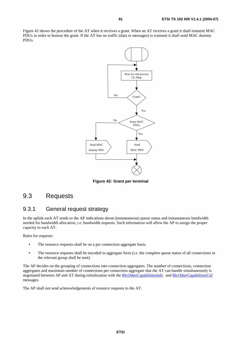
ETSI
ETSI TS 102 000 V1.4.1 (2004-07) 91
Figure 42 shows the procedure of the AT when it receives a grant. When an AT receives a grant it shall transmit MAC PDUs in order to honour the grant. If the AT has no traffic (data or messages) to transmit it shall send MAC dummy PDUs.
Wait for and process UL-Map
Grant?
Some MAC PDUs
Send
MAC PDU
Send MAC
dummy PDU
No
Yes
Yes
No
Figure 42: Grant per terminal
9.3 Requests
9.3.1 General request strategy
In the uplink each AT sends to the AP indications about (instantaneous) queue status and instantaneous bandwidth needed for bandwidth allocation, i.e. bandwidth requests. Such information will allow the AP to assign the proper capacity to each AT.
Rules for requests:
• The resource requests shall be on a per connection aggregate basis.
• The resource requests shall be encoded in aggregate form (i.e. the complete queue status of all connections in the relevant group shall be sent).
The AP decides on the grouping of connections into connection aggregates. The number of connections, connection aggregates and maximum number of connections per connection aggregate that the AT can handle simultaneously is negotiated between AP and AT during initialization with the RlcOtherCapabilitiesInfo and RlcOtherCapabilitiesCnf messages.
The AP shall not send acknowledgements of resource requests to the AT.

ETSI
ETSI TS 102 000 V1.4.1 (2004-07) 92
The three possible signalling mechanisms in the UL for bandwidth requests are specified in the following clauses:
• per MAC PDU header;
• per RlcBandwidthReq MAC management message;
• per queue status report procedure.
9.3.2 Requests per MAC PDU header
Every MAC data PDU in the UL transports, within its header, a request for bandwidth allocations.
The request format is clear from the MAC PDU header for the UL as defined by table 16. A total of 26 bits (3 bytes and 2 bit) are needed for the bandwidth request:
• CID (16 bits): the connection ID is exactly that assigned to the particular connection whose PDU is transmitted in the burst. The CID associated to the bandwidth request identifies the connection aggregate that MAC Data PDU belongs to.
• PB (8 bits): the request byte (piggyback field) describes the number of PDUs in the queue for the connection aggregate associated with the connection aggregate of the MAC data PDU.
• PM (1 bit): the poll-me bit is used to indicate whether the AT has traffic to send or not for the connection aggregates associated to the poll-me bit with the exclusion of the connection aggregate specified by the CID field.
PM = 1 means poll-me and PM = 0 means do not poll-me.
• RSB (1 bit): a request for an UL grant to send a short MAC signalling PDU. If the AP replies with a grant, then this can be used for all MAC management messages that fit into a short MAC signalling PDU, e.g. measurement reports, bandwidth request, connection control messages, etc.
RSB = 1 means request and RSB = 0 means no request.
The three fields PB, PM and RSB are also addressed as the GM (Grant Management) field with 10 bit.
The use of RSB is shown in diagram 1. The RSB bit shall be set to 1 only in one long uplink MAC PDU and not in all subsequent MAC PDUs. Only in case of expiration of T_RSB, the RSB shall be set to 1 again (supposed that the AT has still the need for a short MAC signalling PDU).
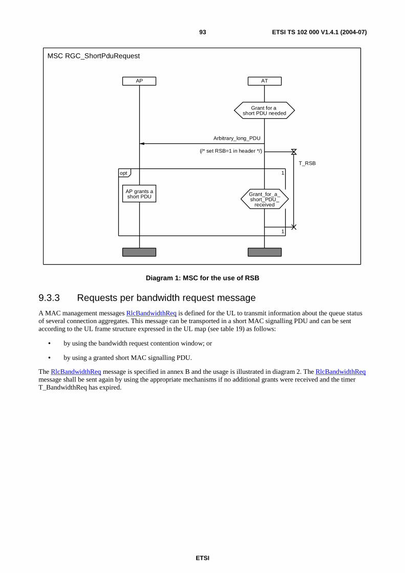
ETSI
ETSI TS 102 000 V1.4.1 (2004-07) 93
AP AT
1
1opt
AP grants ashort PDU
Grant for a short PDU needed
Grant_for_a_short_PDU_
received
MSC RGC_ShortPduRequest
T_RSB
Arbitrary_long_PDU
(/* set RSB=1 in header */)
Diagram 1: MSC for the use of RSB
9.3.3 Requests per bandwidth request message
A MAC management messages RlcBandwidthReq is defined for the UL to transmit information about the queue status of several connection aggregates. This message can be transported in a short MAC signalling PDU and can be sent according to the UL frame structure expressed in the UL map (see table 19) as follows:
• by using the bandwidth request contention window; or
• by using a granted short MAC signalling PDU.
The RlcBandwidthReq message is specified in annex B and the usage is illustrated in diagram 2. The RlcBandwidthReq message shall be sent again by using the appropriate mechanisms if no additional grants were received and the timer T_BandwidthReq has expired.
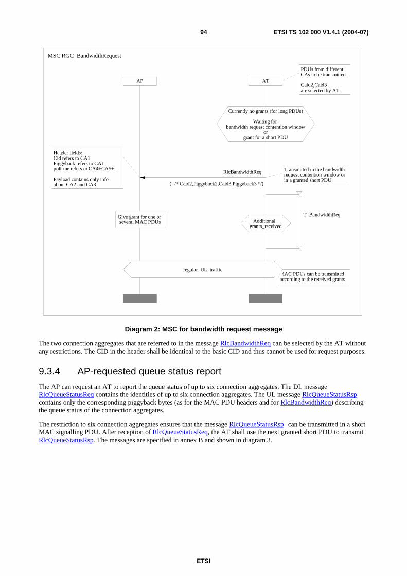
ETSI
ETSI TS 102 000 V1.4.1 (2004-07) 94
AP AT
PDUs from different CAs to be transmitted.
Caid2,Caid3are selected by AT
MAC PDUs can be transmittedaccording to the received grants
regular_UL_traffic
Currently no grants (for long PDUs)
Waiting for bandwidth request contention window
orgrant for a short PDU
Additional_grants_received
Transmitted in the bandwidthrequest contention window orin a granted short PDU
Header fields: Cid refers to CA1Piggyback refers to CA1 poll-me refers to CA4+CA5+...
Payload contains only infoabout CA2 and CA3
Give grant for one or several MAC PDUs
MSC RGC_BandwidthRequest
T_BandwidthReq
RlcBandwidthReq
( /* Caid2,Piggyback2,Caid3,Piggyback3 */)
Diagram 2: MSC for bandwidth request message
The two connection aggregates that are referred to in the message RlcBandwidthReq can be selected by the AT without any restrictions. The CID in the header shall be identical to the basic CID and thus cannot be used for request purposes.
9.3.4 AP-requested queue status report
The AP can request an AT to report the queue status of up to six connection aggregates. The DL message RlcQueueStatusReq contains the identities of up to six connection aggregates. The UL message RlcQueueStatusRsp contains only the corresponding piggyback bytes (as for the MAC PDU headers and for RlcBandwidthReq) describing the queue status of the connection aggregates.
The restriction to six connection aggregates ensures that the message RlcQueueStatusRsp can be transmitted in a short MAC signalling PDU. After reception of RlcQueueStatusReq, the AT shall use the next granted short PDU to transmit RlcQueueStatusRsp. The messages are specified in annex B and shown in diagram 3.
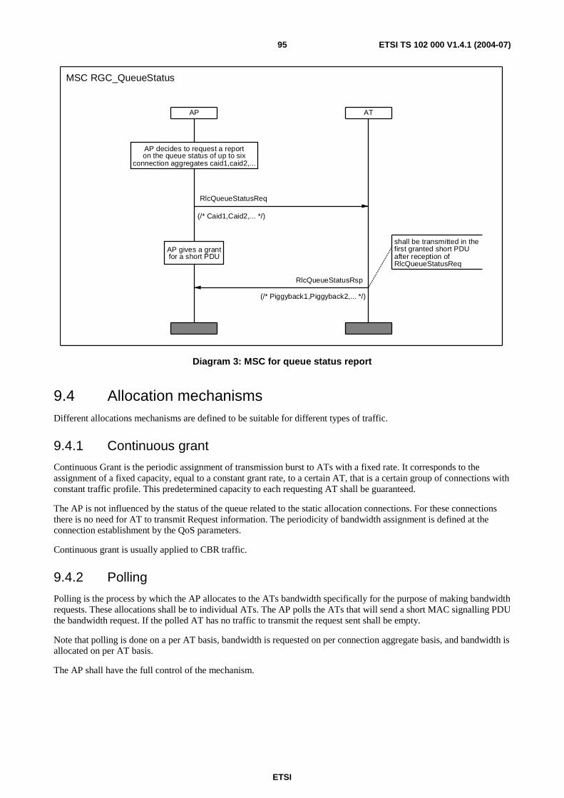
ETSI
ETSI TS 102 000 V1.4.1 (2004-07) 95
AP AT
AP gives a grantfor a short PDU
shall be transmitted in the first granted short PDU after reception of RlcQueueStatusReq
AP decides to request a reporton the queue status of up to six
connection aggregates caid1,caid2,...
MSC RGC_QueueStatus
RlcQueueStatusRsp
(/* Piggyback1,Piggyback2,... */)
RlcQueueStatusReq
(/* Caid1,Caid2,... */)
Diagram 3: MSC for queue status report
9.4 Allocation mechanisms Different allocations mechanisms are defined to be suitable for different types of traffic.
9.4.1 Continuous grant
Continuous Grant is the periodic assignment of transmission burst to ATs with a fixed rate. It corresponds to the assignment of a fixed capacity, equal to a constant grant rate, to a certain AT, that is a certain group of connections with constant traffic profile. This predetermined capacity to each requesting AT shall be guaranteed.
The AP is not influenced by the status of the queue related to the static allocation connections. For these connections there is no need for AT to transmit Request information. The periodicity of bandwidth assignment is defined at the connection establishment by the QoS parameters.
Continuous grant is usually applied to CBR traffic.
9.4.2 Polling
Polling is the process by which the AP allocates to the ATs bandwidth specifically for the purpose of making bandwidth requests. These allocations shall be to individual ATs. The AP polls the ATs that will send a short MAC signalling PDU the bandwidth request. If the polled AT has no traffic to transmit the request sent shall be empty.
Note that polling is done on a per AT basis, bandwidth is requested on per connection aggregate basis, and bandwidth is allocated on per AT basis.
The AP shall have the full control of the mechanism.
ETSI
ETSI TS 102 000 V1.4.1 (2004-07) 96
9.4.3 Piggyback
All the MAC data PDUs have within the header a bandwidth request field. The piggyback byte describes the number of PDUs in the queue for the connection aggregate including the connection of the MAC data PDU.
The first 255 combinations refer to 0 to 254 data PDUs, the last all-one combination means 255 or more PDUs in the queue.
The use of piggyback is sketched in figure 43.
9.4.4 Poll-me bit
Poll-me bit is a form of piggyback mechanism. It is a request of polling and the format is represented by one bit added in every PDU header.
During the connection set-up procedure, the configuration of the poll-me bit, active or non-active, is set in conformance to the connection aggregate the connection belongs to. The configuration of the poll-me bit is under the full control of the AP.
The poll-me bit shall be used to indicate whether the AT has traffic to send or not for the connection aggregates associated with the poll-me bit with the exclusion of the one that the CID of the MAC PDU belongs to.
The use of poll-me bit and piggyback is sketched in figure 43.
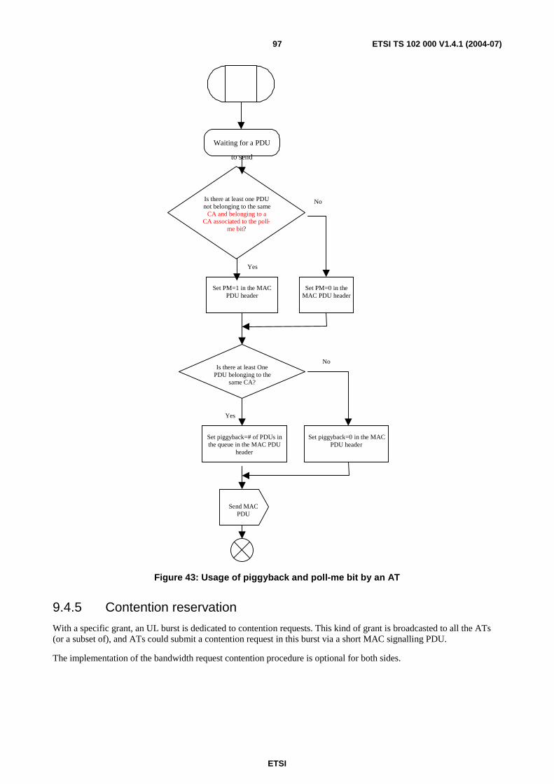
ETSI
ETSI TS 102 000 V1.4.1 (2004-07) 97
Waiting for a PDU
to send
Is there at least one PDUnot belonging to the same
CA and belonging to aCA associated to the poll-
me bit?
Set PM=1 in the MACPDU header
Yes
No
Send MACPDU
Is there at least OnePDU belonging to the
same CA?
Set piggyback=# of PDUs inthe queue in the MAC PDU
header
Set piggyback=0 in the MACPDU header
Yes
No
Set PM=0 in theMAC PDU header
Figure 43: Usage of piggyback and poll-me bit by an AT
9.4.5 Contention reservation
With a specific grant, an UL burst is dedicated to contention requests. This kind of grant is broadcasted to all the ATs (or a subset of), and ATs could submit a contention request in this burst via a short MAC signalling PDU.
The implementation of the bandwidth request contention procedure is optional for both sides.
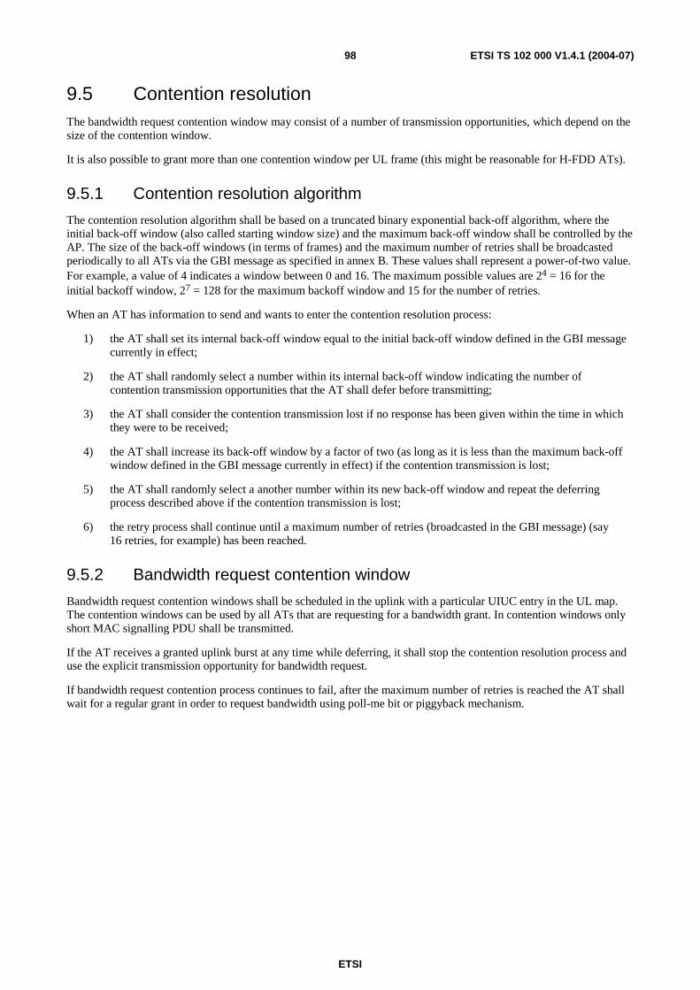
ETSI
ETSI TS 102 000 V1.4.1 (2004-07) 98
9.5 Contention resolution The bandwidth request contention window may consist of a number of transmission opportunities, which depend on the size of the contention window.
It is also possible to grant more than one contention window per UL frame (this might be reasonable for H-FDD ATs).
9.5.1 Contention resolution algorithm
The contention resolution algorithm shall be based on a truncated binary exponential back-off algorithm, where the initial back-off window (also called starting window size) and the maximum back-off window shall be controlled by the AP. The size of the back-off windows (in terms of frames) and the maximum number of retries shall be broadcasted periodically to all ATs via the GBI message as specified in annex B. These values shall represent a power-of-two value. For example, a value of 4 indicates a window between 0 and 16. The maximum possible values are 24 = 16 for the initial backoff window, 27 = 128 for the maximum backoff window and 15 for the number of retries.
When an AT has information to send and wants to enter the contention resolution process:
1) the AT shall set its internal back-off window equal to the initial back-off window defined in the GBI message currently in effect;
2) the AT shall randomly select a number within its internal back-off window indicating the number of contention transmission opportunities that the AT shall defer before transmitting;
3) the AT shall consider the contention transmission lost if no response has been given within the time in which they were to be received;
4) the AT shall increase its back-off window by a factor of two (as long as it is less than the maximum back-off window defined in the GBI message currently in effect) if the contention transmission is lost;
5) the AT shall randomly select a another number within its new back-off window and repeat the deferring process described above if the contention transmission is lost;
6) the retry process shall continue until a maximum number of retries (broadcasted in the GBI message) (say 16 retries, for example) has been reached.
9.5.2 Bandwidth request contention window
Bandwidth request contention windows shall be scheduled in the uplink with a particular UIUC entry in the UL map. The contention windows can be used by all ATs that are requesting for a bandwidth grant. In contention windows only short MAC signalling PDU shall be transmitted.
If the AT receives a granted uplink burst at any time while deferring, it shall stop the contention resolution process and use the explicit transmission opportunity for bandwidth request.
If bandwidth request contention process continues to fail, after the maximum number of retries is reached the AT shall wait for a regular grant in order to request bandwidth using poll-me bit or piggyback mechanism.

ETSI
ETSI TS 102 000 V1.4.1 (2004-07) 99
In figure 44 is sketched the bandwidth request contention process performed by an AT.
Set internal back-off (z) equal to the initial back-off window defined in the UCD
Set a number (x) within z randomly
Wait for bandwidth contention window
Perform the transmission in the xth opportunity
Grant received?
Grant?
Time Y expired?
Set z = 2z
Retries equal to
maximum? Yes
No
No
No
Yes
Yes
No
Yes
Waiting for a regular grant
Figure 44: Contention algorithm for bandwidth request
The time Y (waiting time for a grant) shall be 100 ms.
9.5.3 Contention opportunities acknowledgments
Each bit in the 8-bit ContentionOppsAck field from the broadcast frame information of the control zone in frame #(N+3) refers to one opportunity of the contention window of frame #N.
The bits in the ContentionOppsAck byte are defined as follows:
• 0 indicates correct reception of a valid bandwidth request message. The AT that has used this opportunity shall not perform a re-transmission of the bandwidth request very soon even if it receives no grant.
• 1 indicates no reception of a valid bandwidth request message or a detected collision (e.g. by an indication of the burst receiver or RS decoder). All ATs that have used this opportunity shall perform a re-transmission of the bandwidth request according to the contention resolution algorithm.
NOTE: This scheme avoids all unnecessary re-transmissions of bandwidth requests.

ETSI
ETSI TS 102 000 V1.4.1 (2004-07) 100
The first bit of the ContentionOppsAck byte refers to the first opportunity of the contention window (or first contention window in case that there are more than one contention windows per frame).
• If there were less than 8 contention opportunities per frame, then the remaining bits are set to 1.
• If there were more than 8 contention opportunities per frame, then the mechanism described above is only applied to the first seven bits. The eighth bit is set to 0 if all remaining opportunities were received with valid bandwidth requests message and set to 1 otherwise.
10 Initialization Control (IC)
10.1 Overview Initialization is the procedure that occurs when an AT enters into the network. At the end of the initialization process the AT becomes operational. Initialization is a general term that includes the following cases:
• A new AT enters into the network.
• After PSI (Power Supply Interruption), breakdown or replacement of AT equipment.
• An already initialized AT loses the radio link; this may happen due to deep rain fading or co-channel interference (may affect both or only one direction).
• Malfunction of the AP, e.g. loss of the status of the AT and its parameters or breakdown of the AP.
In the first two cases the process is named first initialization, while in the other two cases the process is named re-initialization. Differences between first initialization and re-initialization are mainly related to the fact that during re-initialization a new frequency scanning procedure is not required and consequently the process of re-initialization is easier and faster.
Initialization is always invited, i.e. the AP knows the AT MAC address in advance and the AP knows when to perform a first initialization (e.g. AP knows that AT need initial access) or re-initialization (e.g. AP is aware of link interruptions).
10.2 Process of initialization The initialization process shall be divided into the following steps:
• DL frequency scanning (search within the DL channels of full RF block).
• Synchronization acquisition (carrier, phase, clock, by processing the DL frame preamble).
• UL and DL transmission parameters acquisition (by decoding the control zone in PHY mode #0 and the PHY mode region #1 used for broadcast messages including the reception of the broadcasted GBI message RlcGeneralBroadcastInformation).
• Initial ranging: during this phase of UL and DL transmissions the AT gets:
- TID (to be used instead of AT MAC address for all other addressing or identification of AT).
- CIDs for management connections (basic, primary and secondary).
- Transmit timing offset (and thus TD and RTD).
- UL transmit power level.
NOTE: Timing and transmit power settings are also updated during regular operation by the message RlcUplinkCorrection.
The whole UL communication during ranging is restricted to the use of granted UL ranging bursts.

ETSI
ETSI TS 102 000 V1.4.1 (2004-07) 101
From the AP point of view, after reception of the RlcRangingAck message the ranging process is finished and the AP shall start to give regular grants.
From the AT point of view, after reception of the RlcRangingSuccess message and reception of another message not related to ranging, the ranging process is finished.
• Physical capabilities negotiation (informs AP about ATs DL and UL PHY capabilities and AP commands on what to use).
• AT authentication (including AK transmission and first TEK allocation).
• Other AT capabilities negotiation (maximum numbers of CIDs and CAs, etc.).
After these steps the AT is called operational and connections can be established (and allocated to connection aggregates and security associations).

ETSI
ETSI TS 102 000 V1.4.1 (2004-07) 102
The overview of the entire initialization process is reported in diagram 4, where the upper left entry refers to first initialization when an AT enters the network for the first time and the upper right entry represents the situation after a link loss.
CapabilitiesNegotiationandAuthenticationon request of AP
Start with oldcarrier successful
Start with old carrier not succesful
MSC IC_InitializationOverview 1(1)
IC_Ranging
Downlink_frequency_scanning_according_to_list
UL_and_DL_parameters_aquisition
Synchronisation_aquisition
IC_PhyCapabilitiesNegotiation
SC_Authentication
IC_OtherCapabilitiesNegotiation
AT_not_installed Link_Loss
Start_with_old_carrier
CC_AT_init__Connection_
_Addition
CC_AP_init__Connection_
_Addition
SC_TekAllocationFirst
Diagram 4: HMSC for AT activities and states for initialization

ETSI
ETSI TS 102 000 V1.4.1 (2004-07) 103
10.3 Steps from frequency scanning to downlink synchronization
10.3.1 Frequency scanning
The first operation that the AT shall perform is the frequency scanning. Before installation the list of possible downlink RF channels (all downlink frequency available in the RF block assigned to an operator) shall be stored in the AT non-volatile storage. Any change on this list shall be communicated by the RlcFrequencyList message.
NOTE: If the list of possible downlink RF channels contains only one entry, then automatically frequency scanning is not applied.
The AT shall order all scanned frequencies in a descending order based on the signal strength and select the frequency with the strongest received DL signal power. The scanning process shall be restricted to those frequencies that are supported by the AT (note that the AP is informed during PHY capabilities negotiation about the AT's RF channel range in order to guarantee successful handover).
During first installation of the AT equipment, it should also be possible to apply further restrictions of the scanning range in order to perform antenna pointing (a correct orientation of the antenna is recommended before scanning, however, the antenna alignment requires an active DL carrier with continuous traffic from the desired AP).
The frequency scanning step during re-initialization is very similar to that during initialization with the simplification that AT shall try to find first the DL frequency used during previous operations. If AT does not find this frequency, then it shall go to next frequency in the ordered list of frequencies, where time constraints for trying the next frequency are not specified.
10.3.2 Synchronization acquisition
The AT modem shall synchronize, in time and frequency, to the preamble of the DL frame. Once the PHY layer has achieved synchronization, the MAC sublayer shall decode the control zone. As it has received and decoded at least one control zone, the AT achieves the frame synchronization and remains synchronized until it fails to receive or decode control zones. If the timer T_synchronization elapsed before a map has been received and decoded, the AT shall come back to the DL frequency scanning step. The synchronization acquisition step shall be as in figure 45.
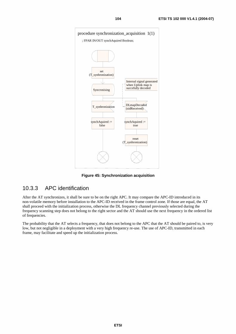
ETSI
ETSI TS 102 000 V1.4.1 (2004-07) 104
procedure synchronization_acquisition 1(1)
set (T_synhronization)
Syncronising
T_synhronization
synchAquired := false
DLmapDecoded (sidReceived)
synchAquired := true
reset (T_synhronization)
Internal signal generated when Uplink map is succefully decoded
; FPAR IN/OUT synchAquired Boolean;
Figure 45: Synchronization acquisition
10.3.3 APC identification
After the AT synchronizes, it shall be sure to be on the right APC. It may compare the APC-ID introduced in its non-volatile memory before installation to the APC-ID received in the frame control zone. If those are equal, the AT shall proceed with the initialization process, otherwise the DL frequency channel previously selected during the frequency scanning step does not belong to the right sector and the AT should use the next frequency in the ordered list of frequencies.
The probability that the AT selects a frequency, that does not belong to the APC that the AT should be paired to, is very low, but not negligible in a deployment with a very high frequency re-use. The use of APC-ID, transmitted in each frame, may facilitate and speed up the initialization process.
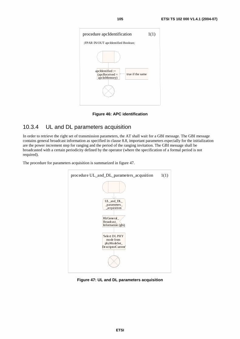
ETSI
ETSI TS 102 000 V1.4.1 (2004-07) 105
;FPAR IN/OUT apcIdentified Boolean;
procedure apcIdentification 1(1)
apcIdentified := (apcReceived = apcInMemory)
true if the same
Figure 46: APC identification
10.3.4 UL and DL parameters acquisition
In order to retrieve the right set of transmission parameters, the AT shall wait for a GBI message. The GBI message contains general broadcast information as specified in clause 8.8, important parameters especially for the initialization are the power increment step for ranging and the period of the ranging invitation. The GBI message shall be broadcasted with a certain periodicity defined by the operator (where the specification of a formal period is not required).
The procedure for parameters acquisition is summarized in figure 47.
procedure UL_and_DL_parameters_acqusition 1(1)
UL_and_DL__parameters__acquisition
RlcGeneral_Broadcast_Information (gbi)
'Select DL PHY mode from
phyModeSet_DescriptorCurrent'
Figure 47: UL and DL parameters acquisition
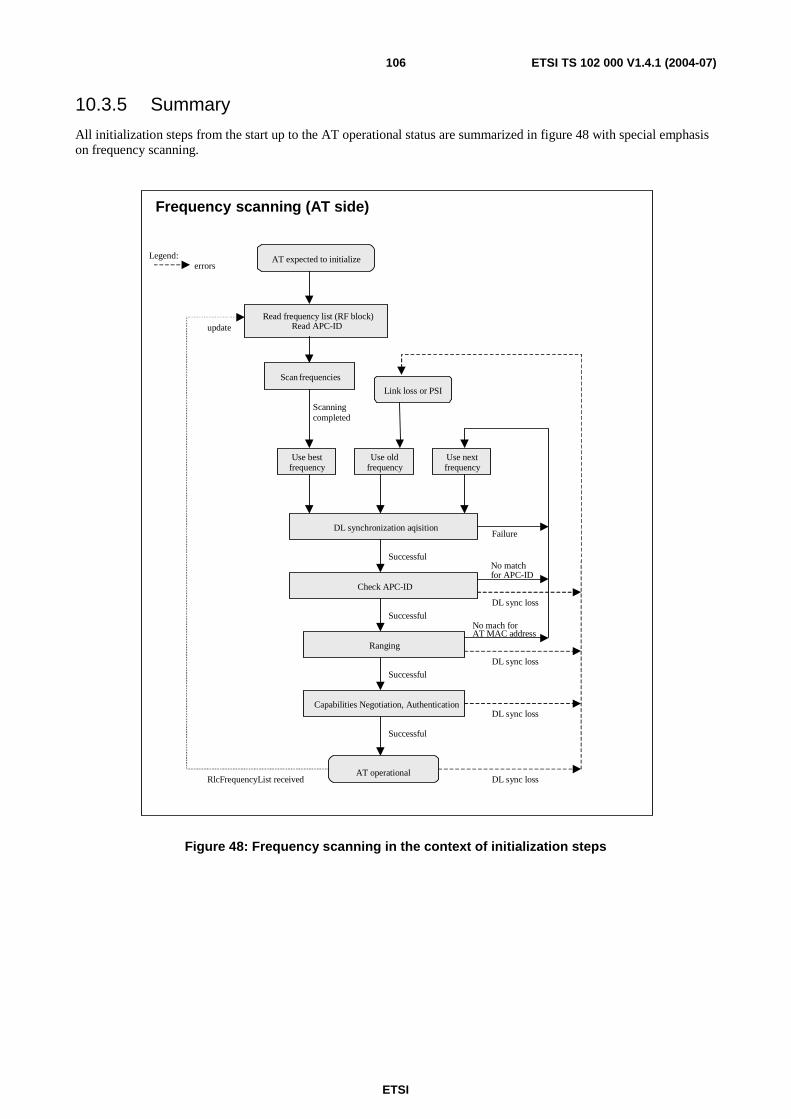
ETSI
ETSI TS 102 000 V1.4.1 (2004-07) 106
10.3.5 Summary
All initialization steps from the start up to the AT operational status are summarized in figure 48 with special emphasis on frequency scanning.
Frequency scanning (AT side)
Legend: errors
AT expected to initialize
Read frequency list (RF block) Read APC-ID
Scan frequencies
Use best frequency
Use old frequency
Use next frequency
DL synchronization aqisition
Check APC-ID
Ranging
Capabilities Negotiation, Authentication
AT operational
update
RlcFrequencyList received
Scanning completed
Successful
Failure
No match for APC-ID
Link loss or PSI
Successful
Successful
Successful
DL sync loss
DL sync loss
DL sync loss
DL sync loss
No mach for AT MAC address
Figure 48: Frequency scanning in the context of initialization steps
ETSI
ETSI TS 102 000 V1.4.1 (2004-07) 107
10.4 Ranging
10.4.1 Overview
The ranging process is required in order that the AT shall be able to get:
• the right timing offset so that its transmission is aligned to a symbol that marks the beginning of MAC frame (the PHY layer timing delays shall be relatively constant); and
• the right Tx power parameters that it will use during normal operations.
The ranging process shall be started as soon as the AT has acquired the right frequency, synchronization and uplink transmission parameters and after the reception of the RlcRangingInvitation message. The RlcRangingInvitation message contains the AT MAC address to identify the AT and provides the binding between the AT MAC address and the TID. Moreover, the RlcRangingInvitation message contains the CIDs and CAIDs for the three management connections and the current power level of the transmitted signal of the AP (apTxPowerIndication parameter).
After reception of the RlcRangingInvitation message and before transmission of the RlcRangingComplete messages (including the message itself), the AT is only allowed to transmit with granted ranging bursts.
The ranging process is started with the reception of the RlcRangingInvitation message. At this point the AT can calculate an estimation of the proper transmission power level to be used in the first ranging burst by analysing the link attenuation derived as difference between transmitted and received power in the downlink and applying a proper backoff. Exact figures for this starting power ATtxPower do not need to be standardized provided that the terminal transmits the first ranging burst with a somewhat lower power than the operative transmission power.
The AT uses each ranging grant to send an RlcRangingReq message with increasing transmit power, starting from ATtxPower, where the transmit power increments are specified in the GBI message.
• If the AT receives an RlcRangingContinues message then it adapts its transmit power and timing according to this message and waits for next ranging grant to send an RlcRangingReq message.
• If the AT receives an RlcRangingSuccess message then it adapts its transmit power and timing according to this message and waits for the next ranging grant to send an RlcRangingAck message.
• After transmission of the RlcRangingAck message, the AT has to respond:
- to a ranging grant with the RlcRangingReq message and increased transmit power (error case);
- to a normal grant with a regular transmission (normal case).
• Whenever the AT receives two subsequent ranging grants without an RlcRangingContinue or RlcRangingSuccess message in between (indicates loss of message in DL), then it shall return to the transmit power increase mechanism. The same applies whenever the AT receives two messages without a ranging grant in between (AP error).
The AP shall not give ranging grants in the same frame as it transmits the RlcRangingContinue or RlcRangingSuccess message.
However, it should be noted that there is no rule how to combine RlcRangingInvitation messages and ranging grants, since the first requires DL capacity and the latter UL capacity. So several RlcRangingInvitation messages between two ranging grants are allowed (but not recommended), but also several ranging grants between two RlcRangingInvitation messages (recommended). In other words, RlcRangingInvitation message and ranging grants can be given whenever there is free capacity in the DL or UL frame, so the ranging process does not cause any considerable overhead at all.
If no RlcRangingInvitation message was transmitted for any AT, then the AP should not give any ranging grants. However, if the AT receives a ranging grant without having received an RlcRangingInvitation message, then it shall ignore the ranging grant.
A maximum gap between two subsequent RlcRangingInvitation messages to the same AT shall be transmitted in the GBI message in order to limit waiting times during the frequency scanning process.
ETSI
ETSI TS 102 000 V1.4.1 (2004-07) 108
The AT will usually receive several RlcRangingInvitation messages during ranging. If there are different TID or CID values in the RlcRangingInvitation messages (this should not appear under normal conditions), then the AT shall return to the start of the ranging procedure.
The RlcRangingInvitation, RlcRangingContinue and RlcRangingSuccess messages shall be transmitted with the most robust PHY mode #1.
If an RlcRangingInvitation message is received during normal operation, then the AT shall stop all transmissions, wait for ranging grants and start from the updated ATtxPower. After reaction to an RlcRangingInvitation message, the AT shall ignore all further RlcRangingInvitation messages. The AP stops issuing RlcRangingInvitation messages after reception of the first RlcRangingReq message. The AT can react again to an RlcRangingInvitation messages after InitializationStatus = InitializationFinished in one of the initialization DL messages.
The RlcRangingInvitation message contains also the command to the AT on the use of the preamble length of normal UL burst (16 or 32 symbols) whereas the ranging bursts always have a 32-symbol preamble. Note that is information is needed at AT side before the start of the PHY capabilities negotiation.
The messages for ranging (RlcRangingInvitation, RlcRangingReq, RlcRangingContinue, RlcRangingSuccess and RlcRangingAck) are specified in detail in annex B.

ETSI
ETSI TS 102 000 V1.4.1 (2004-07) 109
10.4.2 Ranging described with MSC diagrams
Diagram 5 shows the basic principle of the ranging procedure.
ATAP
1
1loop <0, k>
1
1loop <0, m>
If RlcRangingAck is not received then RlcRangingSuccess has to be resent
AP shall continue to grantranging bursts (untilranging is finished)
Stop sendingRlcRangingInvitation
AP shall startsending regulargrants
several transmissions with increasing TxPower, until RlcRangingContinue orRlcRangingSuccess is received
Save Tid, Cids
Further receptions ofRlcRangingInvitationdo not restart theranging process
AP knows AtMacAddress
Sending repeated until RlcRangingReq is received
RangingCompleted
RangingGrant_Received Transmit with the
adapted TxPower
Transmit with theincreased TxPower
AT is not allowedto transmit outsideof ranging bursts unless rangingis finished
Transmit with theadapted TxPower
RangingGrant_Received
RangingGrant_Received
RangingGrant_Received
Synchronization_established_RlcGeneralBroadcastInformation_read
MSC IC_Ranging
RlcRangingSuccess
(/* TimingAdjustRanging,UplinkPowerIncRanging,InitializationStatus */ )
RlcRangingContinue
(/* TimingAdjustRanging,UplinkPowerIncRanging */ )
RlcRangingAck
( /*RangingStatus */)
RlcRangingInvitation
(/* AtMacAddress,Tid,Cids,Caids,ApTxPowerIndication,UplinkPreambleLength */ )
T_RangingAckT_RangingAck
RlcRangingReq
( /* RangingStatus */)
RlcRangingReq
( /* RangingStatus */)
RlcRangingReq
( /* RangingStatus */)
Diagram 5: MSC for the ranging principle
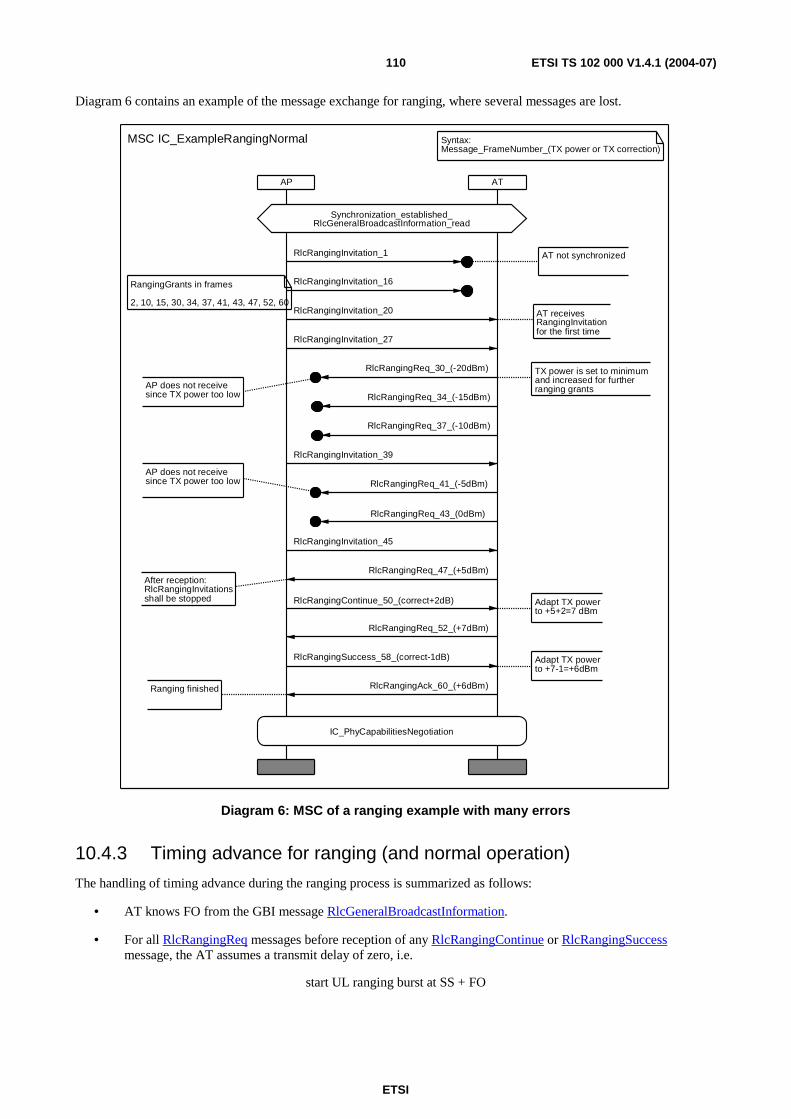
ETSI
ETSI TS 102 000 V1.4.1 (2004-07) 110
Diagram 6 contains an example of the message exchange for ranging, where several messages are lost.
AP AT
RangingGrants in frames
2, 10, 15, 30, 34, 37, 41, 43, 47, 52, 60
Syntax: Message_FrameNumber_(TX power or TX correction)
Ranging finished
Adapt TX powerto +7-1=+6dBm
Adapt TX powerto +5+2=7 dBm
After reception:RlcRangingInvitationsshall be stopped
AP does not receivesince TX power too low
TX power is set to minimumand increased for furtherranging grantsAP does not receive
since TX power too low
AT receives RangingInvitationfor the first time
IC_PhyCapabilitiesNegotiation
Synchronization_established_RlcGeneralBroadcastInformation_read
AT not synchronized
MSC IC_ExampleRangingNormal
RlcRangingReq_52_(+7dBm)
RlcRangingAck_60_(+6dBm)
RlcRangingSuccess_58_(correct-1dB)
RlcRangingContinue_50_(correct+2dB)
RlcRangingReq_47_(+5dBm)
RlcRangingInvitation_45
RlcRangingReq_43_(0dBm)
RlcRangingReq_41_(-5dBm)
RlcRangingInvitation_39
RlcRangingReq_37_(-10dBm)
RlcRangingReq_34_(-15dBm)
RlcRangingReq_30_(-20dBm)
RlcRangingInvitation_27
RlcRangingInvitation_20
RlcRangingInvitation_16
RlcRangingInvitation_1
Diagram 6: MSC of a ranging example with many errors
10.4.3 Timing advance for ranging (and normal operation)
The handling of timing advance during the ranging process is summarized as follows:
• AT knows FO from the GBI message RlcGeneralBroadcastInformation.
• For all RlcRangingReq messages before reception of any RlcRangingContinue or RlcRangingSuccess message, the AT assumes a transmit delay of zero, i.e.
start UL ranging burst at SS + FO
ETSI
ETSI TS 102 000 V1.4.1 (2004-07) 111
• For all RlcRangingReq messages after reception of the absolute value timingAdjustRanging in RlcRangingContinue or RlcRangingSuccess messages, the AT assumes a propagation delay of timingAdjustRanging /2, i.e.
start UL ranging burst at SS + FO − timingAdjustRanging
• For all normal UL bursts after completion of ranging, the AT shall use the incremental timing advance parameter timingAdjustFine from the RlcUplinkCorrection message in the following way:
start UL burst at SS + FO − tnew, where tnew = told − timingAdjustFine
NOTE: A positive (or negative) value of timingAdjustFine means delay (or advance) transmission. See also clause 11.3.5.
The timing advance refers to the round trip delay and not to the one-way propagation delay.
An error in the transition from second to third bullet in the preceding list (i.e. missed or wrong RlcRangingContinue message) has only temporary impact and is corrected by the next correct RlcRangingContinue message.
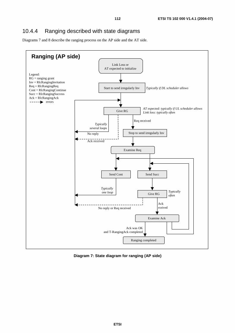
ETSI
ETSI TS 102 000 V1.4.1 (2004-07) 112
10.4.4 Ranging described with state diagrams
Diagrams 7 and 8 describe the ranging process on the AP side and the AT side.
Give RG
Examine Req
Send Cont
Ranging (AP side)
Ranging completed
Typicallyseveral loops
Typicallyone loop
Legend:RG = ranging grantInv = RlcRangingInvitationReq = RlcRangingReqCont = RlcRangingContinueSucc = RlcRangingSuccessAck = RlcRangingAck errors
Req received
No reply
Ack received
Send Succ
Give RG
No reply or Req received
Examine Ack
Ackrceived
Ack was OKand T-RangingAck completed
Link Loss orAT expected to initialize
Start to send irregularly Inv
AT expected: typically if UL scheduler allowsLink loss: typically often
Typicallyoften
Typically if DL scheduler allows
Stop to send irregularly Inv
Diagram 7: State diagram for ranging (AP side)
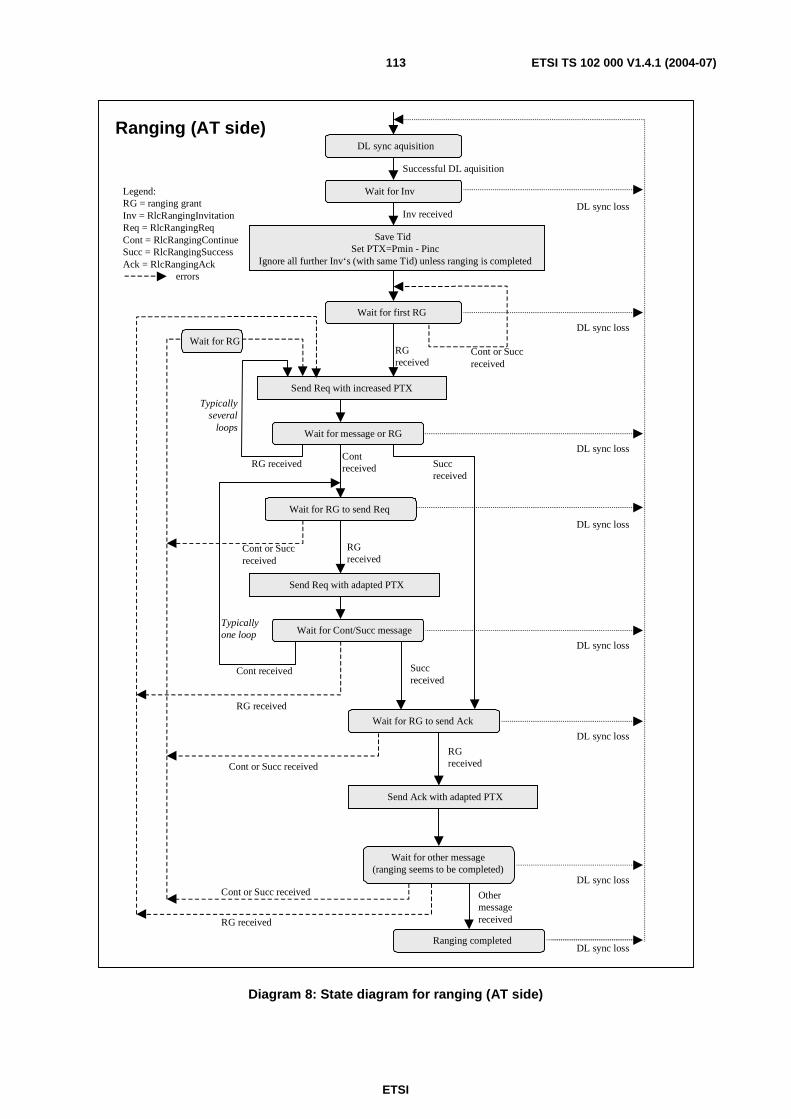
ETSI
ETSI TS 102 000 V1.4.1 (2004-07) 113
DL sync aquisition
Wait for Inv
Successful DL aquisition
Save Tid Set PTX=Pmin - Pinc
Ignore all further Inv‘s (with same Tid) unless ranging is completed
Wait for first RG
Inv received
Send Req with increased PTX
Wait for message or RG
Cont or Succ received
RG received
Wait for RG to send Req
Contreceived
Send Req with adapted PTX
RG received
Wait for Cont/Succ message
Cont received
RG received
Ranging (AT side)
Wait for RG to send Ack
Succ received
Succ received
Send Ack with adapted PTX
Wait for other message (ranging seems to be completed)
Cont or Succ received
RG received
Ranging completed
Other message received
Typicallyseveral
loops
Typicallyone loop
Cont or Succ received
RG received
Cont or Succ received
Legend:RG = ranging grantInv = RlcRangingInvitationReq = RlcRangingReqCont = RlcRangingContinueSucc = RlcRangingSuccessAck = RlcRangingAck errors
DL sync loss
DL sync loss
DL sync loss
DL sync loss
DL sync loss
DL sync loss
DL sync loss
DL sync loss
Wait for RG
RG received
Diagram 8: State diagram for ranging (AT side)
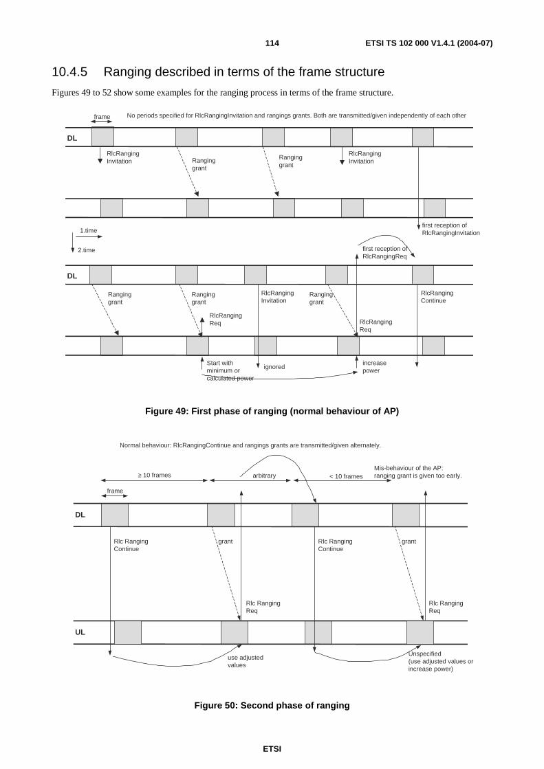
ETSI
ETSI TS 102 000 V1.4.1 (2004-07) 114
10.4.5 Ranging described in terms of the frame structure
Figures 49 to 52 show some examples for the ranging process in terms of the frame structure.
first reception ofRlcRangingInvitation
frame
Ranginggrant
RlcRangingInvitation
DL
2.time
RlcRangingInvitation
1.time
DL
RlcRangingInvitation
Start withminimum orcalculated power
RlcRangingReq
ignored
RlcRangingContinue
RlcRangingReq
increasepower
Ranginggrant
Ranginggrant
Ranginggrant
Ranginggrant
first reception ofRlcRangingReq
No periods specified for RlcRangingInvitation and rangings grants. Both are transmitted/given independently of each other
Figure 49: First phase of ranging (normal behaviour of AP)
frame
≥ 10 frames < 10 frames
Rlc RangingContinue
Rlc RangingContinue
grantgrant
Rlc RangingReq
Rlc RangingReq
use adjustedvalues
DL
UL
Unspecified(use adjusted values orincrease power)
arbitrary
Normal behaviour: RlcRangingContinue and rangings grants are transmitted/given alternately.
Mis-behaviour of the AP:ranging grant is given too early.
Figure 50: Second phase of ranging
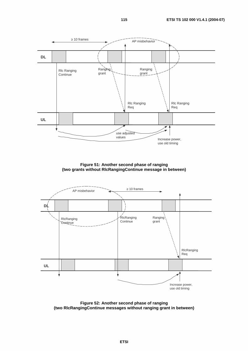
ETSI
ETSI TS 102 000 V1.4.1 (2004-07) 115
≥ 10 frames
Rlc RangingContinue
Ranginggrant
Rlc RangingReq
Ranginggrant
Rlc RangingReq
use adjustedvalues
UL
DL
Increase power,use old timing
AP misbehavior
Figure 51: Another second phase of ranging (two grants without RlcRangingContinue message in between)
≥ 10 frames
RlcRangingContinue
RlcRangingReq
UL
DL
Increase power,use old timing
RlcRangingContinue
Ranginggrant
AP misbehavior
Figure 52: Another second phase of ranging (two RlcRangingContinue messages without ranging grant in between)
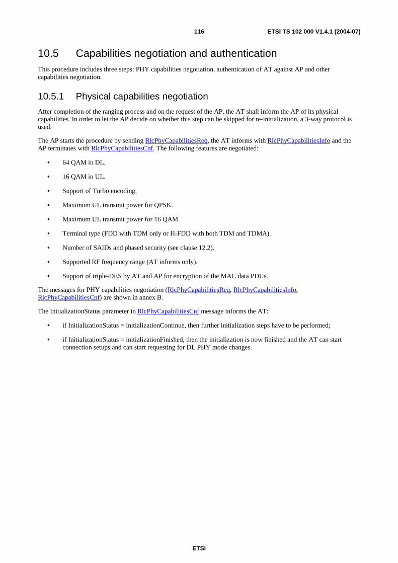
ETSI
ETSI TS 102 000 V1.4.1 (2004-07) 116
10.5 Capabilities negotiation and authentication This procedure includes three steps: PHY capabilities negotiation, authentication of AT against AP and other capabilities negotiation.
10.5.1 Physical capabilities negotiation
After completion of the ranging process and on the request of the AP, the AT shall inform the AP of its physical capabilities. In order to let the AP decide on whether this step can be skipped for re-initialization, a 3-way protocol is used.
The AP starts the procedure by sending RlcPhyCapabilitiesReq, the AT informs with RlcPhyCapabilitiesInfo and the AP terminates with RlcPhyCapabilitiesCnf. The following features are negotiated:
• 64 QAM in DL.
• 16 QAM in UL.
• Support of Turbo encoding.
• Maximum UL transmit power for QPSK.
• Maximum UL transmit power for 16 QAM.
• Terminal type (FDD with TDM only or H-FDD with both TDM and TDMA).
• Number of SAIDs and phased security (see clause 12.2).
• Supported RF frequency range (AT informs only).
• Support of triple-DES by AT and AP for encryption of the MAC data PDUs.
The messages for PHY capabilities negotiation (RlcPhyCapabilitiesReq, RlcPhyCapabilitiesInfo, RlcPhyCapabilitiesCnf) are shown in annex B.
The InitializationStatus parameter in RlcPhyCapabilitiesCnf message informs the AT:
• if InitializationStatus = initializationContinue, then further initialization steps have to be performed;
• if InitializationStatus = initializationFinished, then the initialization is now finished and the AT can start connection setups and can start requesting for DL PHY mode changes.
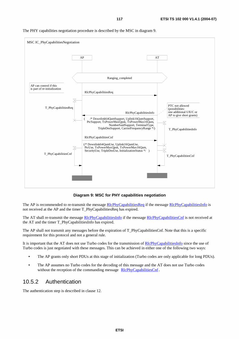
ETSI
ETSI TS 102 000 V1.4.1 (2004-07) 117
The PHY capabilities negotiation procedure is described by the MSC in diagram 9.
ATAP
Ranging_completed
PTC not allowed (possibilities:one additional UIUC orAP to give short grants)
AP can control if thisis part of re-initialization
MSC IC_PhyCapabilitiesNegotiation
RlcPhyCapabilitiesCnf
(/* Downlink64QamUse, Uplink16QamUse,PtcUse, TxPowerMaxQpsk, TxPowerMax16Qam,SecurityUse, TripleDesUse, InitializationStatus */ )
RlcPhyCapabilitiesInfo
( /* Downlink64QamSupport, Uplink16QamSupport,PtcSupport, TxPowerMaxQpsk, TxPowerMax16Qam,
NumberSaidSupport, TerminalType,TripleDesSupport, CarrierFrequencyRange */)
T_PhyCapabilitiesCnfT_PhyCapabilitiesCnf
RlcPhyCapabilitiesReq
T_PhyCapabilitiesReq
T_PhyCapabilitiesInfo
Diagram 9: MSC for PHY capabilities negotiation
The AP is recommended to re-transmit the message RlcPhyCapabilitiesReq if the message RlcPhyCapabilitiesInfo is not received at the AP and the timer T_PhyCapabilitiesReq has expired.
The AT shall re-transmit the message RlcPhyCapabilitiesInfo if the message RlcPhyCapabilitiesCnf is not received at the AT and the timer T_PhyCapabilitiesInfo has expired.
The AP shall not transmit any messages before the expiration of T_PhyCapabilitiesCnf. Note that this is a specific requirement for this protocol and not a general rule.
It is important that the AT does not use Turbo codes for the transmission of RlcPhyCapabilitiesInfo since the use of Turbo codes is just negotiated with these messages. This can be achieved in either one of the following two ways:
• The AP grants only short PDUs at this stage of initialization (Turbo codes are only applicable for long PDUs).
• The AP assumes no Turbo codes for the decoding of this message and the AT does not use Turbo codes without the reception of the commanding message RlcPhyCapabilitiesCnf.
10.5.2 Authentication
The authentication step is described in clause 12.
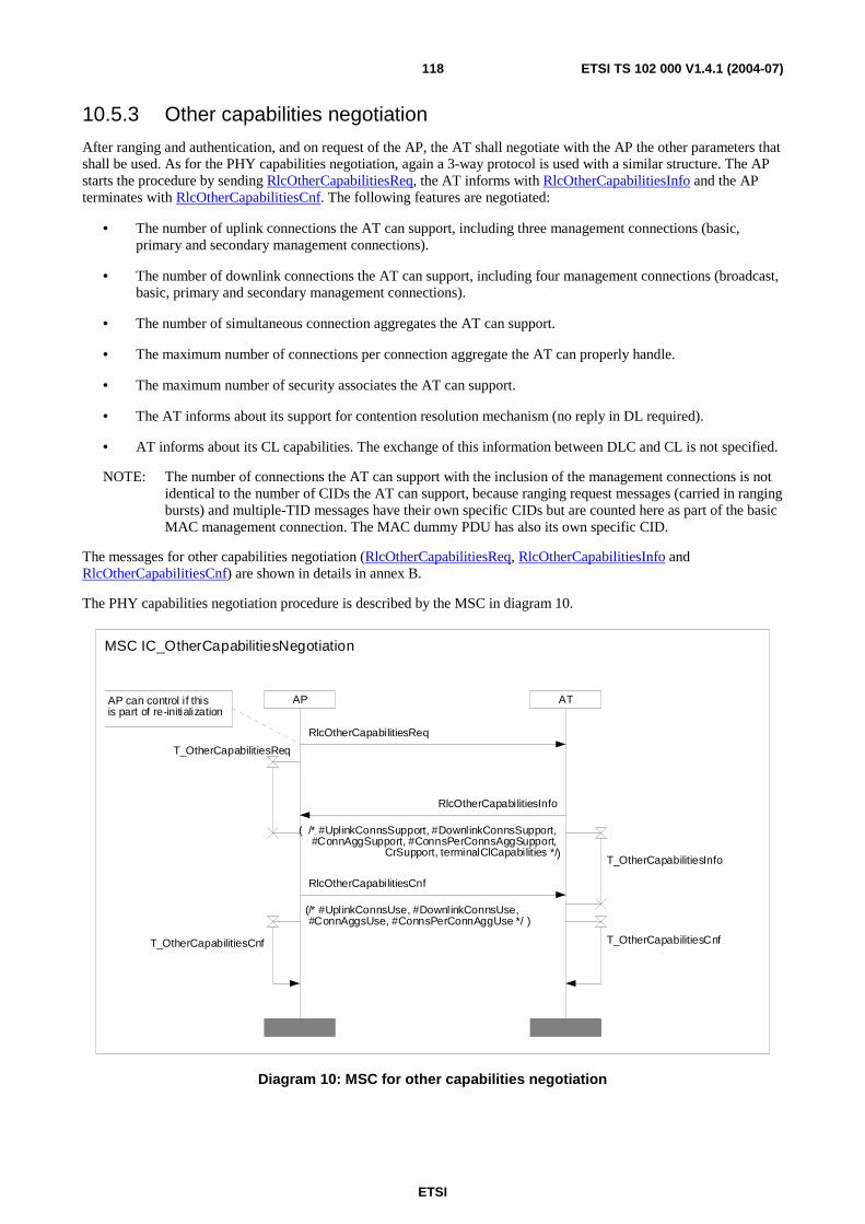
ETSI
ETSI TS 102 000 V1.4.1 (2004-07) 118
10.5.3 Other capabilities negotiation
After ranging and authentication, and on request of the AP, the AT shall negotiate with the AP the other parameters that shall be used. As for the PHY capabilities negotiation, again a 3-way protocol is used with a similar structure. The AP starts the procedure by sending RlcOtherCapabilitiesReq, the AT informs with RlcOtherCapabilitiesInfo and the AP terminates with RlcOtherCapabilitiesCnf. The following features are negotiated:
• The number of uplink connections the AT can support, including three management connections (basic, primary and secondary management connections).
• The number of downlink connections the AT can support, including four management connections (broadcast, basic, primary and secondary management connections).
• The number of simultaneous connection aggregates the AT can support.
• The maximum number of connections per connection aggregate the AT can properly handle.
• The maximum number of security associates the AT can support.
• The AT informs about its support for contention resolution mechanism (no reply in DL required).
• AT informs about its CL capabilities. The exchange of this information between DLC and CL is not specified.
NOTE: The number of connections the AT can support with the inclusion of the management connections is not identical to the number of CIDs the AT can support, because ranging request messages (carried in ranging bursts) and multiple-TID messages have their own specific CIDs but are counted here as part of the basic MAC management connection. The MAC dummy PDU has also its own specific CID.
The messages for other capabilities negotiation (RlcOtherCapabilitiesReq, RlcOtherCapabilitiesInfo and RlcOtherCapabilitiesCnf) are shown in details in annex B.
The PHY capabilities negotiation procedure is described by the MSC in diagram 10.
AP ATAP can control if thisis part of re-initialization
MSC IC_OtherCapabilitiesNegotiation
RlcOtherCapabilitiesCnf
(/* #UplinkConnsUse, #DownlinkConnsUse,#ConnAggsUse, #ConnsPerConnAggUse */ )
RlcOtherCapabilitiesInfo
( /* #UplinkConnsSupport, #DownlinkConnsSupport,#ConnAggSupport, #ConnsPerConnsAggSupport,
CrSupport, terminalClCapabilities */)
T_OtherCapabilitiesCnfT_OtherCapabilitiesCnf
T_OtherCapabilitiesInfo
T_OtherCapabilitiesReq
RlcOtherCapabilitiesReq
Diagram 10: MSC for other capabilities negotiation

ETSI
ETSI TS 102 000 V1.4.1 (2004-07) 119
The AP is recommended to re-transmit the message RlcOtherCapabilitiesReq if the message RlcOtherCapabilitiesInfo is not received at the AP and the timer T_OtherCapabilitiesReq has expired.
The AT shall re-transmit the message RlcOtherCapabilitiesInfo if the message RlcOtherCapabilitiesCnf is not received at the AT and the timer T_OtherCapabilitiesInfo has expired.
10.6 Serial and parallel processes during initialization Figure 53 describes again all steps to be performed during initialization from frequency scanning to other capabilities negotiation. After completion of first TEK allocation (see clause 12) and other capabilities negotiation, the AT is called operational. The entire procedure is called extended initialization.
Connection establishments are only allowed for operational ATs (since otherwise MAC PDUs have to blocked or have to be transmitted unencrypted).
The figure states which processes can be started after completion of the initialization steps. For example, the link supervision mechanisms shall start immediately after completion of ranging and thus before PHY capabilities negotiation (to avoid interruption of UL timing and power correction, see clause 11 for more details), however, the AP has to assume ATs with H-FDD operation until the RlcPhyCapabitiesInfo message is received.
The AT can use the contention window for bandwidth requests for messaging purposes, even if data connection are not yet established. If contention window is not supported by AP or AT (note that the AP is not aware of the AT's capability until RlcOtherCapabilitiesInfo is received), the AP is recommended to give enough grants.
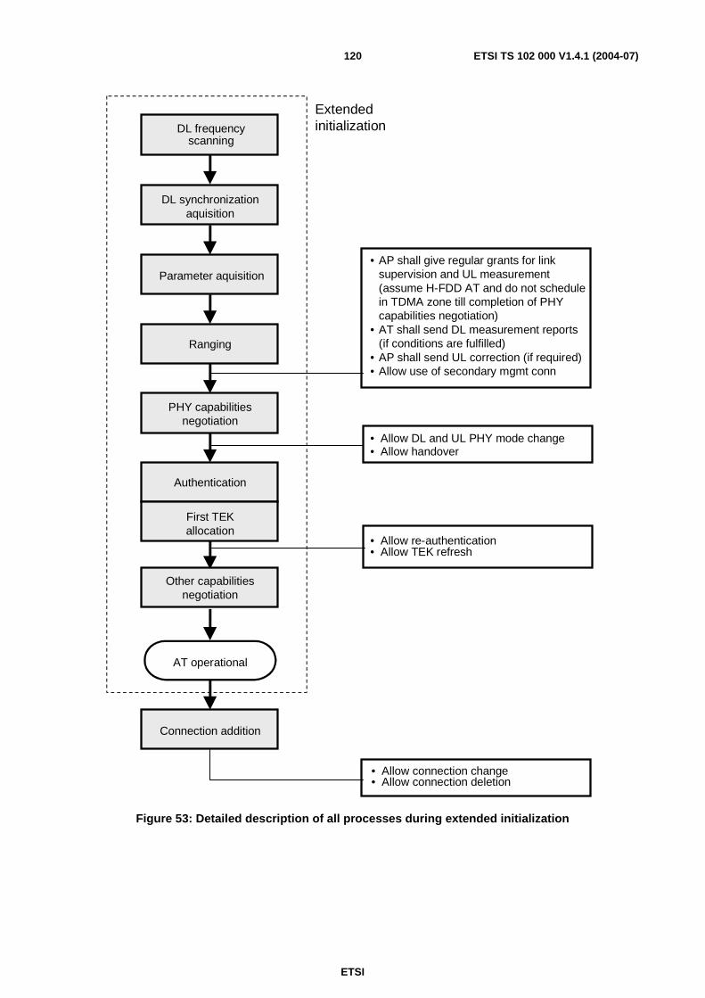
ETSI
ETSI TS 102 000 V1.4.1 (2004-07) 120
DL frequencyscanning
• AP shall give regular grants for linksupervision and UL measurement(assume H-FDD AT and do not schedulein TDMA zone till completion of PHYcapabilities negotiation)
• AT shall send DL measurement reports(if conditions are fulfilled)
• AP shall send UL correction (if required)• Allow use of secondary mgmt conn
DL synchronizationaquisition
Parameter aquisition
Ranging
PHY capabilitiesnegotiation
Authentication
Other capabilitiesnegotiation
First TEKallocation
AT operational
Connection addition
• Allow DL and UL PHY mode change• Allow handover
• Allow re-authentication• Allow TEK refresh
• Allow connection change• Allow connection deletion
Extendedinitialization
Figure 53: Detailed description of all processes during extended initialization
ETSI
ETSI TS 102 000 V1.4.1 (2004-07) 121
11 Radio Resource Control (RRC)
11.1 Overview Radio Resource Control (RRC) is an important part of the Radio Link Control (RLC) sublayer as shown in figure 4. The other three RLC functions are initialization control (IC, see clause 10), security control (SC, see clause 12) and connection control (CC, see clause 13). It should be noted that ARQ is not allocated to the same level but is part of the MAC sublayer (see clause 8.5).
The main functions for radio resource control include the supervision of the radio link (and the start of a new initialization procedure if required), the adaptive change of the DL and UL PHY modes (i.e. adaptive coding and modulation) and the automatic power control for DL (optional) and UL. Other parts are the change of the PHY mode set, load-levelling (inter-channel handover) and the control of the UL structure (i.e. number of FEC blocks per preamble, number of MAC PDUs per UL burst). The present document describes:
• all messages required for the report of measurements and the exchange of information between AT and AP (e.g. measurement of C/N, transmit power and received power);
• all messages or mechanisms for the synchronized change of a parameter (e.g. PHY mode or transmit power or carrier frequency);
• the responsibility (i.e. whether AP or AT or both can or shall change a parameter).
The algorithms and the criteria for a change of a parameter are implementation-specific in most cases and therefore not addressed in the present document.
11.2 Link supervision
11.2.1 Detection of link loss
Possible reasons for link interruptions are as follows:
• Deep rain fading event (applies for DL and UL).
• Interference from other AP (applies for DL, typically time-invariant) or from other AT (applies for UL, typically time-variant).
• PSI (Power Supply Interruption) at AP or AT (affects both DL and UL).
• Equipment failure at AP or AT (with impact on transmit or receive direction or both directions).
The detection of a link interruption is based on the fact that AP gives grants to each AT on a regular basis even if the AT has no traffic data to transmit (the replies to these grants are needed to allow for UL channel measurements at the AP, see clause 11.3).
• If the DL is interrupted, then the AT can detect this by failing to decode the control zone. Since the AT cannot reply to the regular grants from the AP, the AP shall be able to detect the link interruption.
• If the UL is interrupted, then the AP will detect this since the replies of the AT to the regular grants are missing. The AT might not be able to detect the UL interruption very soon.
If the AT receives grants for each frame, then the AP can detect the DL or UL interruption very fast. The AP can detect the link interruption after one or several missing replies in at least two subsequent frames.
ETSI
ETSI TS 102 000 V1.4.1 (2004-07) 122
11.2.2 Reaction on link loss
As a basic principle, the reaction to a link interruption shall be under full control of the AP.
For the definition or detection of a link loss at the AT side and the appropriate reaction of the AT it is not required to define any timers. For the AP side, timers might be required but these are implementation-specific and out of the scope of the present document.
The AT shall always try to maintain or to re-establish as soon as possible the synchronization of the DL (on the same RF channel as before) and to decode the control zone and PHY mode region #1 in order to receive or wait for commands from the AP.
The AP shall react on a link interruption by sending the ranging invitation RlcRangingInvitation and by giving ranging grants to the AT. During the re-initialization process, the AP can command whether the PHY and other capabilities steps and the authentication and key distribution steps shall be skipped or re-performed. The AP can also use the initialization command RlcInitializationCmd for this situation.
The AT shall delete all connection and security settings after reception of a ranging invitation.
The details for AT reaction in case of link loss and during regular operation are shown in diagram 11 and also specified below:
• If the AT receives a ranging grant during regular operation or after a link interruption without having received a ranging invitation, then this ranging grant shall be ignored. This situation can only occur for specific error scenarios.
• If the AT receives an RlcRangingInvitation during regular operation or after a link interruption, then it shall stop all transmissions (if applicable) and shall not reply to any grants other than ranging grants (if applicable) and shall start the ranging procedure and the capabilities negotiation steps (if commanded) by using the granted ranging bursts.
• During the ranging process, repeated RlcRangingInvitation messages shall be ignored after reception of the first RlcRangingInvitation message.
• If the AT lost the DL synchronization (i.e. failed to decode the control zone), then it shall try to re-establish the DL synchronization and wait for further commands.
The details for AP reaction in case of link loss are specified below:
• If the AT does not reply to grants, then the AP shall start to issue irregularly RlcRangingInvitation messages and irregularly ranging grants.
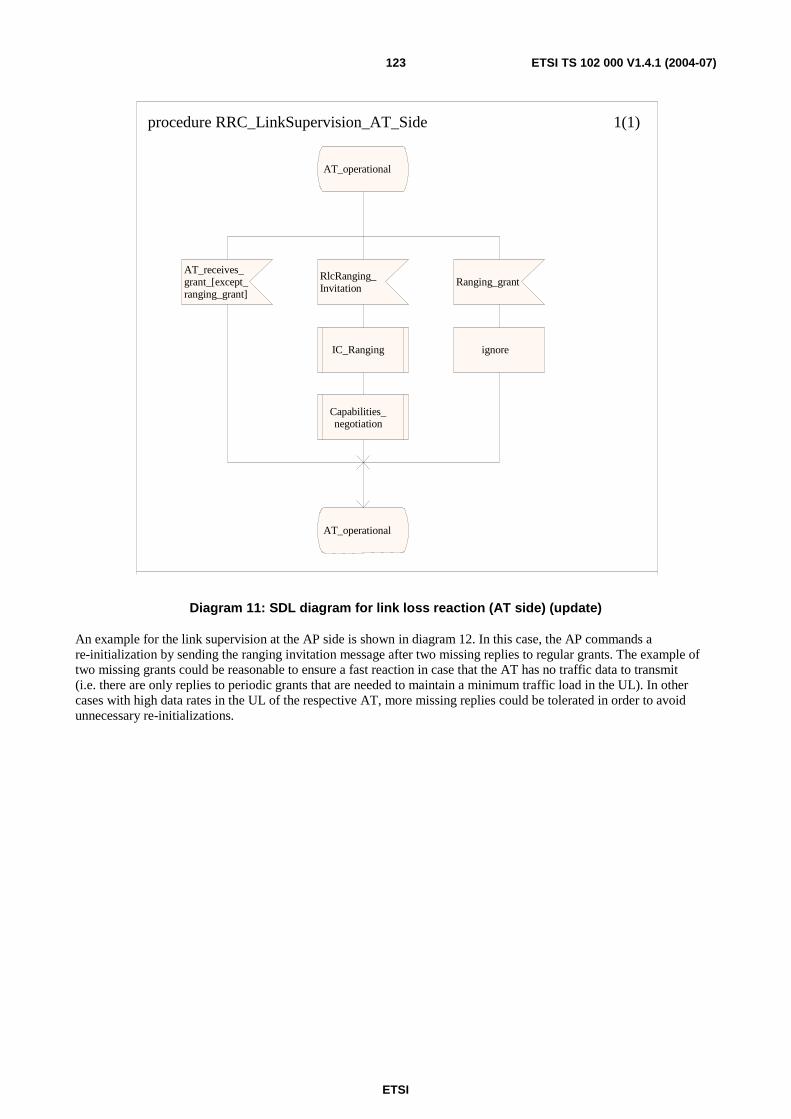
ETSI
ETSI TS 102 000 V1.4.1 (2004-07) 123
procedure RRC_LinkSupervision_AT_Side 1(1)
AT_operational
AT_receives_ grant_[except_ ranging_grant]
AT_operational
RlcRanging_ Invitation
IC_Ranging
Capabilities_ negotiation
Ranging_grant
ignore
Diagram 11: SDL diagram for link loss reaction (AT side) (update)
An example for the link supervision at the AP side is shown in diagram 12. In this case, the AP commands a re-initialization by sending the ranging invitation message after two missing replies to regular grants. The example of two missing grants could be reasonable to ensure a fast reaction in case that the AT has no traffic data to transmit (i.e. there are only replies to periodic grants that are needed to maintain a minimum traffic load in the UL). In other cases with high data rates in the UL of the respective AT, more missing replies could be tolerated in order to avoid unnecessary re-initializations.
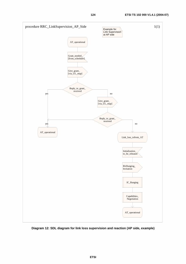
ETSI
ETSI TS 102 000 V1.4.1 (2004-07) 124
procedure RRC_LinkSupervision_AP_Side 1(1)Example for Link Supervisionat AP side
AT_operational
Grant_needed_[from_scheduler]
Give_grant_[via_UL_map]
Reply_to_grant_received
Give_grant_[via_UL_map]
Reply_to_grant_received
AT_operational
Link_loss_tofrom_AT
Initialization_to_be_released
RlcRanging_Invitation
IC_Ranging
Capabilities_Negotiation
AT_operational
noyes
yes no
Diagram 12: SDL diagram for link loss supervision and reaction (AP side, example)
ETSI
ETSI TS 102 000 V1.4.1 (2004-07) 125
11.2.3 Reaction on AT malfunction
In case of a malfunction of the AT the following procedures shall be applied:
• If the DL operation fails then the AT can not establish or re-establish synchronization. The AT can not react on ranging grants or ranging invitations. After some time, the AP is aware of this and can decide to stop any ranging grants or ranging invitations to this AT. The AT does not transmit anything and additional specifications are not given.
• If the UL operations fails or if there is some malfunction (e.g. UL transmit power too high or uncontrollable), then the AP can switch off the AT with the RlcInitializationCmd message as specified in annex B.
For the parameter InitializationCmd, the following rules shall be applied:
• InitializationCmd = rejectedFromNetwork: the AT shall stop all transmissions and the reception and shall not try to synchronize to the network again. The AP shall not give any grants to the AT after this command.
• InitializationCmd = rejectedFromChannel: the AT shall stop all transmissions and the reception and shall not try to synchronize to the same RF channel again. The AT shall be reset completely. The AT is allowed to perform frequency scanning. The AP shall not give any grants to the AT after this command.
• InitializationCmd = firstInitialization: the AT shall stop all transmissions. The AT shall be reset completely and then shall perform a first initialization procedure on the same carrier, started with RlcRangingInvitation. The AP shall not give any grants to the AT after this command except for ranging grants.
• InitializationCmd = transmissionStop: the AT shall stop all transmissions but continue to receive and wait for further commands. The AT shall react on InitializationStatus = transmissionReStart (or on other values of InitializationStatus if applicable) or on RlcRangingInvitation. The AP shall not give grants to the AT after this command except for ranging grants.
• InitializationCmd = transmissionReStart: the AT shall reply to all grants and can use the bandwidth request contention window. It is recommended to use this command only after a short period of silence since the link conditions may have changed otherwise.
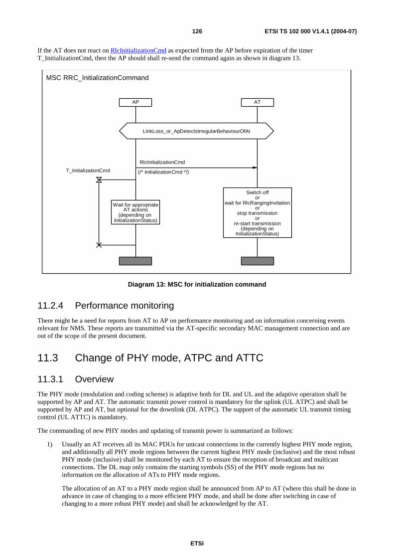
ETSI
ETSI TS 102 000 V1.4.1 (2004-07) 126
If the AT does not react on RlcInitializationCmd as expected from the AP before expiration of the timer T_InitializationCmd, then the AP should shall re-send the command again as shown in diagram 13.
AP AT
LinkLoss_or_ApDetectsIrregularBehaviourOfAt
Wait for appropriateAT actions
(depending on InitializationStatus)
Switch offor
wait for RlcRangingInvitationor
stop transmissionor
re-start transmission(depending on
InitializationStatus)
MSC RRC_InitializationCommand
RlcInitializationCmd
(/* InitializationCmd */)T_InitializationCmd
Diagram 13: MSC for initialization command
11.2.4 Performance monitoring
There might be a need for reports from AT to AP on performance monitoring and on information concerning events relevant for NMS. These reports are transmitted via the AT-specific secondary MAC management connection and are out of the scope of the present document.
11.3 Change of PHY mode, ATPC and ATTC
11.3.1 Overview
The PHY mode (modulation and coding scheme) is adaptive both for DL and UL and the adaptive operation shall be supported by AP and AT. The automatic transmit power control is mandatory for the uplink (UL ATPC) and shall be supported by AP and AT, but optional for the downlink (DL ATPC). The support of the automatic UL transmit timing control (UL ATTC) is mandatory.
The commanding of new PHY modes and updating of transmit power is summarized as follows:
1) Usually an AT receives all its MAC PDUs for unicast connections in the currently highest PHY mode region, and additionally all PHY mode regions between the current highest PHY mode (inclusive) and the most robust PHY mode (inclusive) shall be monitored by each AT to ensure the reception of broadcast and multicast connections. The DL map only contains the starting symbols (SS) of the PHY mode regions but no information on the allocation of ATs to PHY mode regions.
The allocation of an AT to a PHY mode region shall be announced from AP to AT (where this shall be done in advance in case of changing to a more efficient PHY mode, and shall be done after switching in case of changing to a more robust PHY mode) and shall be acknowledged by the AT.
ETSI
ETSI TS 102 000 V1.4.1 (2004-07) 127
A new DL PHY mode can be requested by the AT if certain C/(N+I) thresholds (derived from the received and decoded DL signal) are crossed (where the thresholds themselves are commended by the AP to the ATs in the GBI message) as well as commanded by the AP.
2) The DL transmit power for the complete sector can be changed by the AP without notifying the ATs in advance. The DL transmit power shall be increased only if the current DL transmit power is not high enough for at least one AT in the most robust PHY mode. The DL ATPC is an optional feature.
3) The UL PHY mode is commanded from AP to AT by addressing each active AT (i.e. ATs that receive grants) in the UL map. Each UL map entry consists of the triplet UIUC, TID, SS (where TID is replaced by a specific contention window TID for the contention windows). The UL PHY mode is selected in the AP. For the contention windows (i.e. for non-granted UL transmissions), the most robust PHY mode shall be used.
4) The UL transmit power for each AT is commanded by AT-specific MAC management messages (via basic MAC management connection) when required, i.e. UL transmit power changes are usually only commanded when the rain fading conditions change. During PHY mode switching the AT automatically corrects the transmitted power according to the UplinkPowerModChangeList values broadcast in the GBI message.
The information required at the AP for the appropriate allocation of PHY modes and the appropriate choice of the transmit power is gained as follows:
• The selection of the DL PHY mode and the DL transmit power is under full control of the AP and is based on the DL channel measurements at the ATs and the measurement reports from the ATs to the AP. The parameters to be measured and the reporting mechanisms are specified in detail in the present document.
• The selection of the UL PHY mode and the UL transmit power is under full control of the AP and is based on the UL channel measurements at the AP. Therefore each AT is granted bandwidth appropriately to maintain a minimum traffic load in order to allow for reliable measurements at the AP. More details about the channel measurement procedure in the AP and the calculation of the UL parameters are implementation-specific and thus out of the scope of the present document.
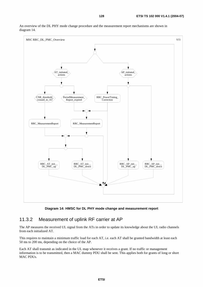
ETSI
ETSI TS 102 000 V1.4.1 (2004-07) 128
An overview of the DL PHY mode change procedure and the measurement report mechanisms are shown in diagram 14.
MSC RRC_DL_PMC_Overview 1(1)
AP_initiated_actions
CNR_threshold_crossed_in_AT
PeriodMeasurement_Report_expired
RRC_AT_init__DL_PMC_up
RRC_AT_init__DL_PMC_down
RRC_AP_init__DL_PMC_up
RRC_AP_init__DL_PMC_down
AT_initiated_actions
RRC_MeasurementReportRRC_MeasurementReport
RRC_PowerTiming_Correction
Diagram 14: HMSC for DL PHY mode change and measurement report
11.3.2 Measurement of uplink RF carrier at AP
The AP measures the received UL signal from the ATs in order to update its knowledge about the UL radio channels from each initialized AT.
This requires to maintain a minimum traffic load for each AT, i.e. each AT shall be granted bandwidth at least each 50 ms to 200 ms, depending on the choice of the AP.
Each AT shall transmit as indicated in the UL map whenever it receives a grant. If no traffic or management information is to be transmitted, then a MAC dummy PDU shall be sent. This applies both for grants of long or short MAC PDUs.

ETSI
ETSI TS 102 000 V1.4.1 (2004-07) 129
11.3.3 Measurement of downlink RF carrier at AT and measurement reports to AP
The AT shall measure the following two parameters from the received DL signal:
• CnrMeasured = measured absolute current C/(N+I) from the received and decoded DL signal; resolution = 8 bit; range = [4, 40] dB; granularity = 0,25 dB. The measurement accuracy is specified with 1 dB and all other details (like averaging period) are implementation-specific.
• RxPowerMeasured = measured absolute current received power of the DL signal; resolution = 8 bit; range = [-88, -28] dBm; granularity = 0,25 dB.
Both parameters are independent of the current DL PHY mode. The measurement report shall also contain the following four parameters:
• TxPowerMeasured = current UL transmit power of the measurement report; resolution = 6 bit, range = [-26, +20] dBm, granularity = 1,0 dB.
• TxPowerMargin = gap between current uplink transmit power and the maximum uplink transmit power; resolution = 6 bit; range = [0, 12] dB; granularity = 0,25 dB.
• DownlinkPhyModeWanted = wanted PHY mode as a result of CnrMeasured; resolution = 3 bit.
• MaxUplinkPhyMode = most efficient PHY mode that is possible for the AT with the current transmitted power; resolution = 3 bit.
• ActualUplinkPhyMode = current UL PHY mode that was used to calculate the TX power parameters.
The measurement report RlcMeasurementReportData message is specified in annex B and is transmitted from AT to AP in the following cases:
• If certain C/(N+I) thresholds are crossed, where these thresholds CnrThreshold are broadcasted with the GBI message for all PHY modes of the current PHY mode set. The thresholds are different for increasing or decreasing channel quality to support hystheresis, see clause 11.3.4 for more details.
• If the parameter MeasurementReportReq in the message RlcUplinkCorrection (used to command power or timing correction to the AT) indicates the AP request, see RlcUplinkCorrectionin annex B. The AP can control that a correction message is always or never or sometimes replied by the report, see the message RlcMeasurementReportCriterium.
• According to the period PeriodReportGeneral in the GBI message. This carrier-specific report period can be overwritten by the PeriodReportAtSpecific parameter contained in the AT-specific message RlcMeasurementReportCriterium, see the message RlcMeasurementReportCriterium in annex B. Switching on/off of periodic reports is possible on a per carrier basis as well as on a per AT basis.
In contrast to many most other messages, the RlcMeasurementReportCriterium message shall not be acknowledged by an explicit message in the uplink direction. If the AT does not change its report behaviour according to the new value of PeriodReportAtSpecific, then the AP should send the message RlcMeasurementReportCriterium again.
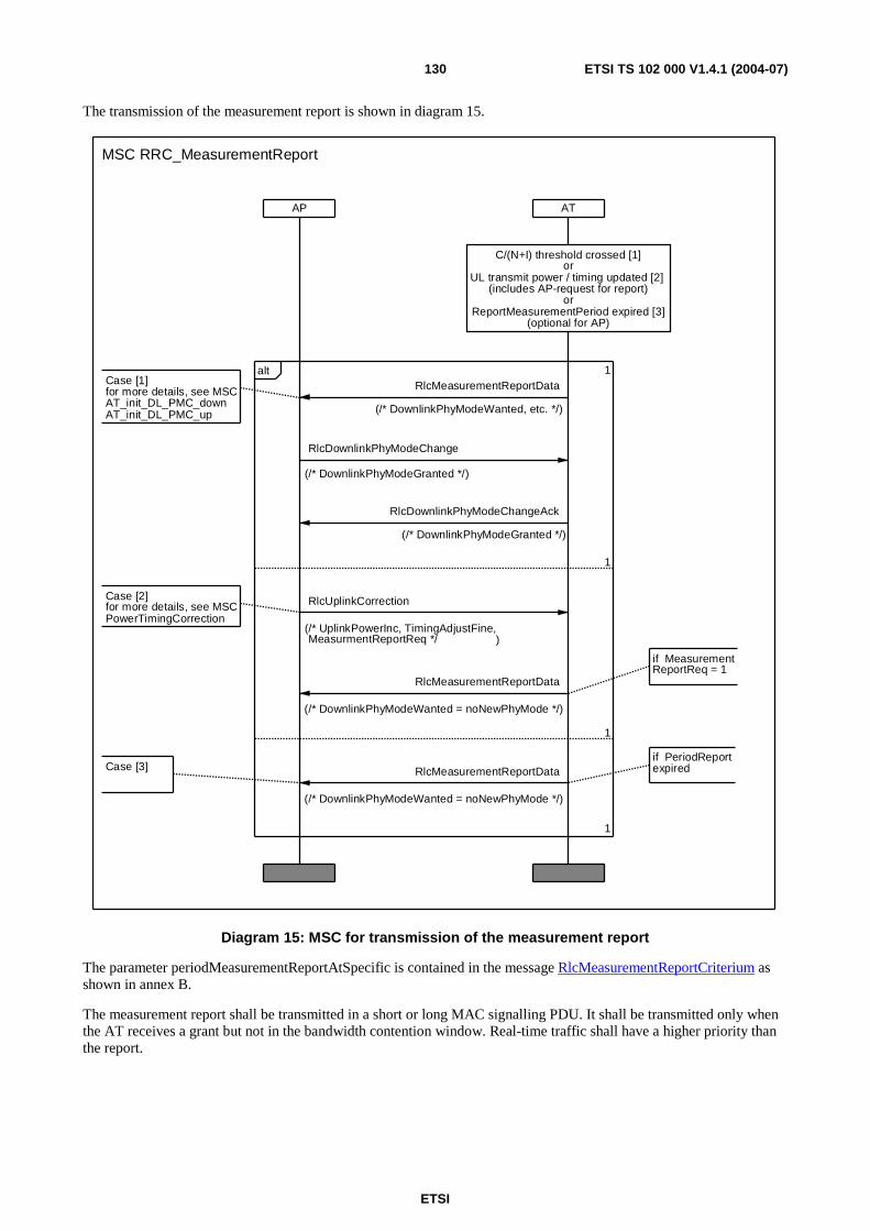
ETSI
ETSI TS 102 000 V1.4.1 (2004-07) 130
The transmission of the measurement report is shown in diagram 15.
ATAP
C/(N+I) threshold crossed [1]or
UL transmit power / timing updated [2] (includes AP-request for report)
orReportMeasurementPeriod expired [3]
(optional for AP)
Case [1]for more details, see MSCAT_init_DL_PMC_downAT_init_DL_PMC_up
1
1alt
Case [3]
1
1
Case [2]for more details, see MSCPowerTimingCorrection
if PeriodReportexpired
if MeasurementReportReq = 1
MSC RRC_MeasurementReport
RlcDownlinkPhyModeChangeAck
(/* DownlinkPhyModeGranted */)
RlcDownlinkPhyModeChange
(/* DownlinkPhyModeGranted */)
RlcMeasurementReportData
(/* DownlinkPhyModeWanted = noNewPhyMode */)
RlcMeasurementReportData
(/* DownlinkPhyModeWanted = noNewPhyMode */)
RlcUplinkCorrection
(/* UplinkPowerInc, TimingAdjustFine,MeasurmentReportReq */ )
RlcMeasurementReportData
(/* DownlinkPhyModeWanted, etc. */)
Diagram 15: MSC for transmission of the measurement report
The parameter periodMeasurementReportAtSpecific is contained in the message RlcMeasurementReportCriterium as shown in annex B.
The measurement report shall be transmitted in a short or long MAC signalling PDU. It shall be transmitted only when the AT receives a grant but not in the bandwidth contention window. Real-time traffic shall have a higher priority than the report.
ETSI
ETSI TS 102 000 V1.4.1 (2004-07) 131
11.3.4 Change of downlink PHY mode
The change of the DL PHY mode can be initiated by AT or AP. Both possibilities shall be supported. More exactly, the DL PHY mode referred to in the following MAC management messages is the current highest PHY mode that shall be monitored by the AT, i.e. the AT shall decode all PHY mode regions between the most robust PHY mode and the highest current PHY mode.
For the AT initiated DL PHY mode change, the AT measures the C/(N+I) ratio of the received DL signal (which is also forwarded to the AP in the measurement report). The AT knows the C/(N+I) thresholds that have been broadcasted to all ATs in the PHY mode set descriptor section of the GBI message (for all PHY modes of the current PHY mode set and the thresholds are different for increasing or decreasing channel quality).
The AT can issue a request for the DL PHY mode change by transmitting the measurement report RlcMeasurementReportData as described in annex B. The request is based on the CnrMeasured value and explicitly stated by downlinkPhyModeWanted, where the value noNewPhyMode shall not be used in this context.
The AP sends a confirmation of the DL PHY mode change request in the DL in form of an announcement RlcDownlinkPhyModeChange and an acknowledgement of this announcement is sent in the UL with the message RlcDownlinkPhyModeChangeAck. These two messages are shown in annex B. It should be noted that the content of these two messages is identical but the messages appear in different contexts.
For the order of the messages two cases have to be distinguished:
• Changing to a more robust PHY mode as shown in diagram 16 (AT initiated) and diagram 18 (AP initiated): The PHY mode switching should be performed as soon as possible after reception of RlcMeasurementReportData and shall be done before the transmission or reception of RlcDownlinkPhyModeChangeand RlcDownlinkPhyModeChangeAck.
• Changing to a more efficient PHY mode as shown in diagram 17 (AT initiated) and diagram 19 (AP initiated): The PHY mode switching shall be performed after the reception of RlcMeasurementReportData and RlcDownlinkPhyModeChange and RlcDownlinkPhyModeChangeAck.
Except for the RlcMeasurementReportData message in the UL for AT initiated DL PHY mode change, the two subsequent messages RlcDownlinkPhyModeChange and RlcDownlinkPhyModeChangeAck are identical for AT or AP initiated DL PHY mode change.
For the AT initiated DL PHY mode changes, the whole procedure is only performed if DownlinkPhyMode = New, since the report RlcMeasurementReportData is also sent in other situations with DownlinkPhyMode = noNewPhyMode. (However, even a reception of RlcMeasurementReportData with DownlinkPhyMode = noNewPhyMode can stimulate the AP to command a DL PHY mode change.)
After transmission of RlcDownlinkPhyModeChange in DL, the reception of RlcDownlinkPhyModeChangeAck is controlled with the timer T_DownlinkPhyModeChange. If this timer expires then RlcDownlinkPhyModeChange shall be repeated.
After transmission of RlcMeasurementReportData in UL with DownlinkPhyMode = New, the reception of RlcDownlinkPhyModeChange is controlled with the timer T_MeasurementReportData. If this timer expires then RlcMeasurementReportData shall be repeated.
If the AT receives RlcDownlinkPhyModeChange (maybe without having sent RlcMeasurementReportData), the AT shall reply with RlcDownlinkPhyModeChangeAck.
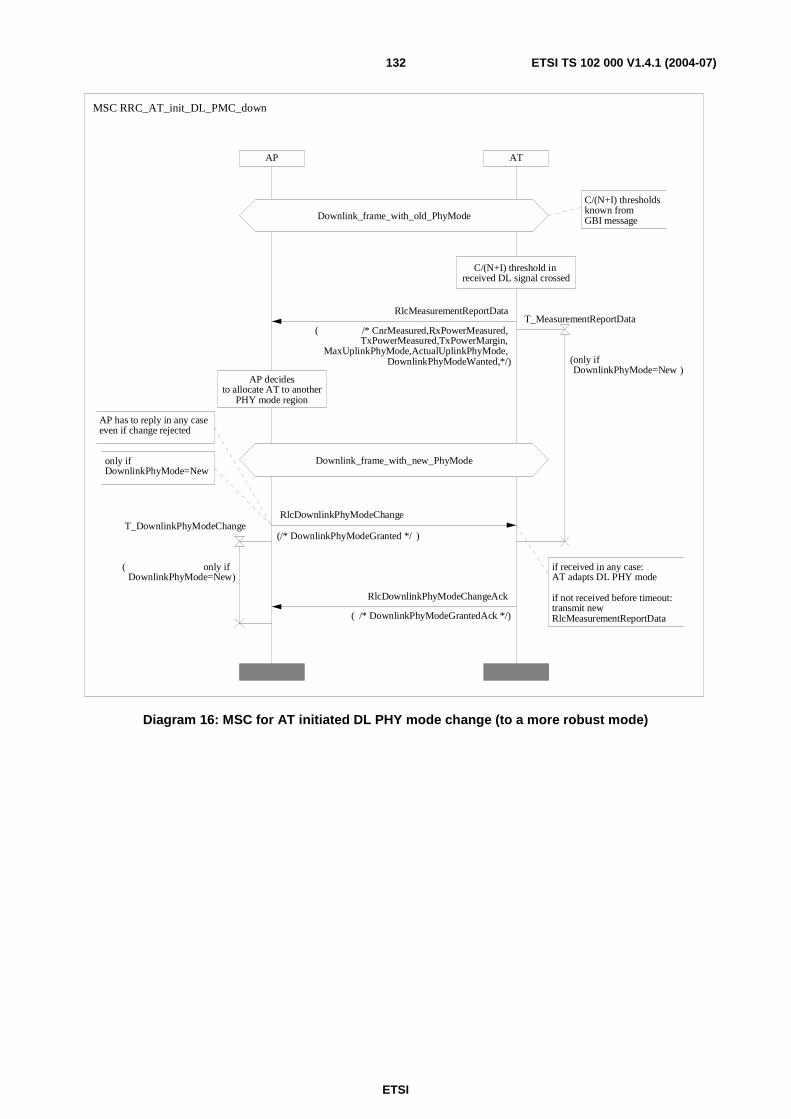
ETSI
ETSI TS 102 000 V1.4.1 (2004-07) 132
ATAP
AP has to reply in any caseeven if change rejected
if received in any case: AT adapts DL PHY mode
if not received before timeout: transmit newRlcMeasurementReportData
only if DownlinkPhyMode=New
AP decidesto allocate AT to another
PHY mode region
Downlink_frame_with_new_PhyMode
C/(N+I) thresholdsknown from GBI messageDownlink_frame_with_old_PhyMode
C/(N+I) threshold in received DL signal crossed
MSC RRC_AT_init_DL_PMC_down
RlcMeasurementReportData
( /* CnrMeasured,RxPowerMeasured,TxPowerMeasured,TxPowerMargin,
MaxUplinkPhyMode,ActualUplinkPhyMode,DownlinkPhyModeWanted,*/)
RlcDownlinkPhyModeChangeAck
( /* DownlinkPhyModeGrantedAck */)
T_DownlinkPhyModeChange
( only if DownlinkPhyMode=New)
RlcDownlinkPhyModeChange
(/* DownlinkPhyModeGranted */ )
T_MeasurementReportData
(only if DownlinkPhyMode=New )
Diagram 16: MSC for AT initiated DL PHY mode change (to a more robust mode)
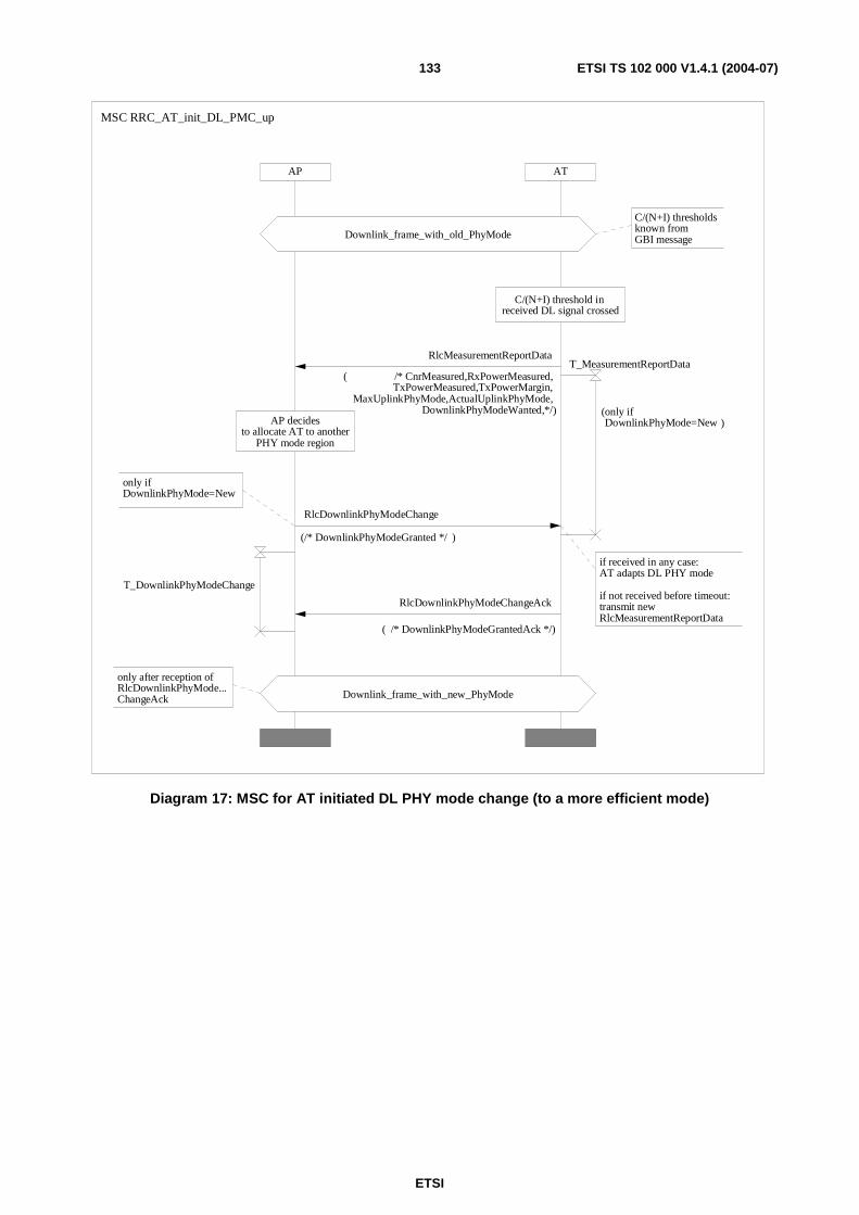
ETSI
ETSI TS 102 000 V1.4.1 (2004-07) 133
AP AT
only after reception ofRlcDownlinkPhyMode...ChangeAck Downlink_frame_with_new_PhyMode
if received in any case: AT adapts DL PHY mode
if not received before timeout: transmit newRlcMeasurementReportData
C/(N+I) threshold in received DL signal crossed
AP decidesto allocate AT to another
PHY mode region
only if DownlinkPhyMode=New
C/(N+I) thresholdsknown from GBI messageDownlink_frame_with_old_PhyMode
MSC RRC_AT_init_DL_PMC_up
RlcMeasurementReportData
( /* CnrMeasured,RxPowerMeasured,TxPowerMeasured,TxPowerMargin,
MaxUplinkPhyMode,ActualUplinkPhyMode,DownlinkPhyModeWanted,*/)
RlcDownlinkPhyModeChangeAck
( /* DownlinkPhyModeGrantedAck */)
T_MeasurementReportData
(only if DownlinkPhyMode=New )
T_DownlinkPhyModeChange
RlcDownlinkPhyModeChange
(/* DownlinkPhyModeGranted */ )
Diagram 17: MSC for AT initiated DL PHY mode change (to a more efficient mode)
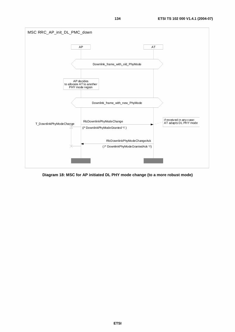
ETSI
ETSI TS 102 000 V1.4.1 (2004-07) 134
AP AT
if received in any case: AT adapts DL PHY mode
Downlink_frame_with_old_PhyMode
Downlink_frame_with_new_PhyMode
AP decidesto allocate AT to another
PHY mode region
MSC RRC_AP_init_DL_PMC_down
RlcDownlinkPhyModeChangeAck
( /* DownlinkPhyModeGrantedAck */)
T_DownlinkPhyModeChangeRlcDownlinkPhyModeChange
(/* DownlinkPhyModeGranted */ )
Diagram 18: MSC for AP initiated DL PHY mode change (to a more robust mode)
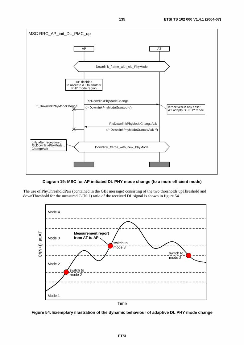
ETSI
ETSI TS 102 000 V1.4.1 (2004-07) 135
ATAP
if received in any case: AT adapts DL PHY mode
only after reception ofRlcDownlinkPhyMode...ChangeAck Downlink_frame_with_new_PhyMode
Downlink_frame_with_old_PhyMode
AP decidesto allocate AT to another
PHY mode region
MSC RRC_AP_init_DL_PMC_up
RlcDownlinkPhyModeChangeAck
(/* DownlinkPhyModeGrantedAck */)
T_DownlinkPhyModeChange
RlcDownlinkPhyModeChange
(/* DownlinkPhyModeGranted */)
Diagram 19: MSC for AP initiated DL PHY mode change (to a more efficient mode)
The use of PhyThresholdPair (contained in the GBI message) consisting of the two thresholds upThreshold and downThreshold for the measured C/(N+I) ratio of the received DL signal is shown in figure 54.
Mode 1
Mode 2
Mode 3
Mode 4
C/(
N+I
) a
t AT
Time
switch tomode 2
switch tomode 3
switch tomode 2
Measurement reportfrom AT to AP
Figure 54: Exemplary illustration of the dynamic behaviour of adaptive DL PHY mode change
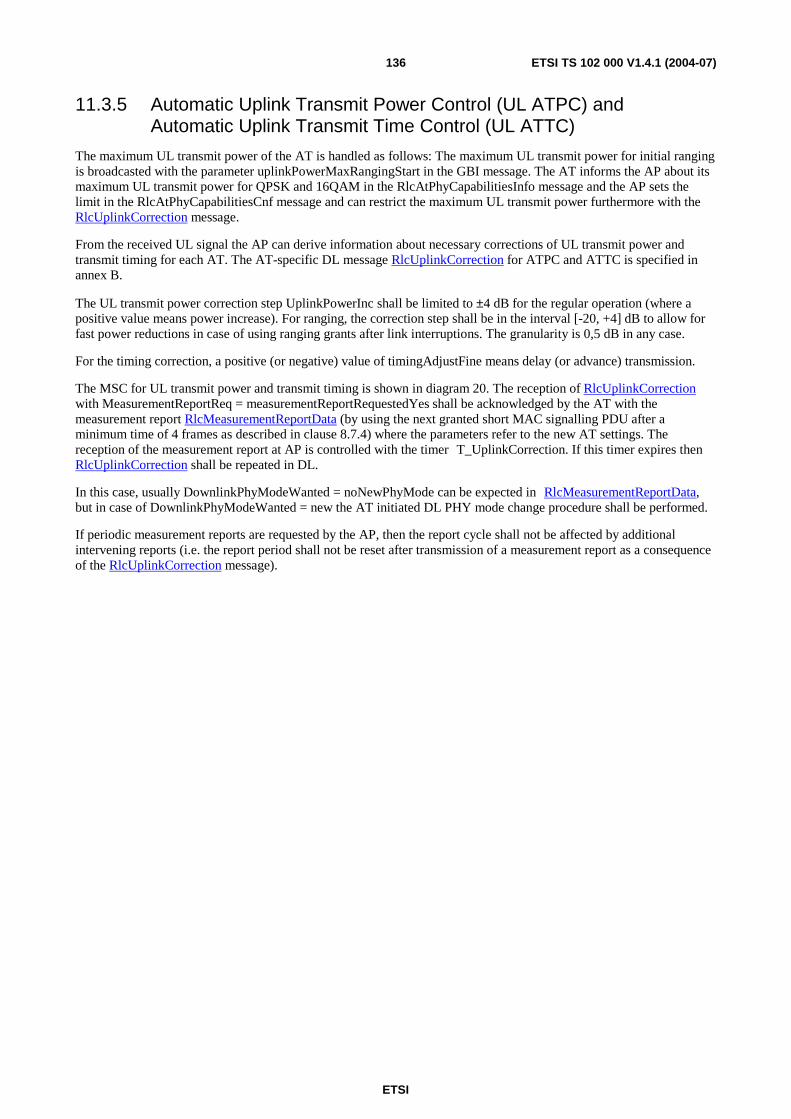
ETSI
ETSI TS 102 000 V1.4.1 (2004-07) 136
11.3.5 Automatic Uplink Transmit Power Control (UL ATPC) and Automatic Uplink Transmit Time Control (UL ATTC)
The maximum UL transmit power of the AT is handled as follows: The maximum UL transmit power for initial ranging is broadcasted with the parameter uplinkPowerMaxRangingStart in the GBI message. The AT informs the AP about its maximum UL transmit power for QPSK and 16QAM in the RlcAtPhyCapabilitiesInfo message and the AP sets the limit in the RlcAtPhyCapabilitiesCnf message and can restrict the maximum UL transmit power furthermore with the RlcUplinkCorrection message.
From the received UL signal the AP can derive information about necessary corrections of UL transmit power and transmit timing for each AT. The AT-specific DL message RlcUplinkCorrection for ATPC and ATTC is specified in annex B.
The UL transmit power correction step UplinkPowerInc shall be limited to ±4 dB for the regular operation (where a positive value means power increase). For ranging, the correction step shall be in the interval [-20, +4] dB to allow for fast power reductions in case of using ranging grants after link interruptions. The granularity is 0,5 dB in any case.
For the timing correction, a positive (or negative) value of timingAdjustFine means delay (or advance) transmission.
The MSC for UL transmit power and transmit timing is shown in diagram 20. The reception of RlcUplinkCorrection with MeasurementReportReq = measurementReportRequestedYes shall be acknowledged by the AT with the measurement report RlcMeasurementReportData (by using the next granted short MAC signalling PDU after a minimum time of 4 frames as described in clause 8.7.4) where the parameters refer to the new AT settings. The reception of the measurement report at AP is controlled with the timer T_UplinkCorrection. If this timer expires then RlcUplinkCorrection shall be repeated in DL.
In this case, usually DownlinkPhyModeWanted = noNewPhyMode can be expected in RlcMeasurementReportData, but in case of DownlinkPhyModeWanted = new the AT initiated DL PHY mode change procedure shall be performed.
If periodic measurement reports are requested by the AP, then the report cycle shall not be affected by additional intervening reports (i.e. the report period shall not be reset after transmission of a measurement report as a consequence of the RlcUplinkCorrection message).
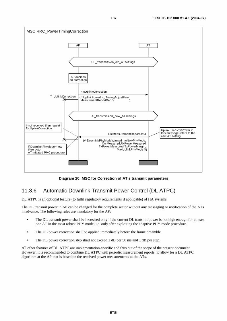
ETSI
ETSI TS 102 000 V1.4.1 (2004-07) 137
AP AT
UL_transmission_new_ATsettings
AP decideson correction
if DownlinkPhyMode=newthen goto AT-initiated PMC procedure
if not received then repeat RlcUplinkCorrection
Uplink TransmitPower in this message refers to thenew AT setting
UL_transmission_old_ATsettings
MSC RRC_PowerTimingCorrection
RlcMeasurementReportData
(/* DownlinkPhyModeWanted=noNewPhyMode,CnrMeasured,RxPowerMeasured
TxPowerMeasured,TxPowerMargin,MaxUplinkPhyMode */)
T_UplinkCorrection
RlcUplinkCorrection
(/* UplinkPowerInc, TimingAdjustFine,MeasurmentReportReq */ )
Diagram 20: MSC for Correction of AT's transmit parameters
11.3.6 Automatic Downlink Transmit Power Control (DL ATPC)
DL ATPC is an optional feature (to fulfil regulatory requirements if applicable) of HA systems.
The DL transmit power in AP can be changed for the complete sector without any messaging or notification of the ATs in advance. The following rules are mandatory for the AP:
• The DL transmit power shall be increased only if the current DL transmit power is not high enough for at least one AT in the most robust PHY mode, i.e. only after exploiting the adaptive PHY mode procedure.
• The DL power correction shall be applied immediately before the frame preamble.
• The DL power correction step shall not exceed 1 dB per 50 ms and 1 dB per step.
All other features of DL ATPC are implementation-specific and thus out of the scope of the present document. However, it is recommended to combine DL ATPC with periodic measurement reports, to allow for a DL ATPC algorithm at the AP that is based on the received power measurements at the ATs.
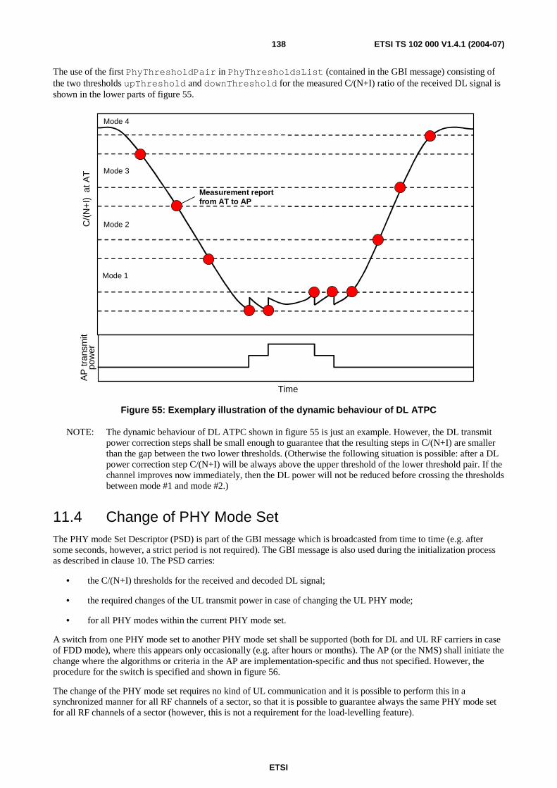
ETSI
ETSI TS 102 000 V1.4.1 (2004-07) 138
The use of the first PhyThresholdPair in PhyThresholdsList (contained in the GBI message) consisting of the two thresholds upThreshold and downThreshold for the measured C/(N+I) ratio of the received DL signal is shown in the lower parts of figure 55.
Mode 1
Mode 2
Mode 3
Mode 4
C/(
N+I
) a
t AT
Time
Measurement reportfrom AT to AP
AP
tran
smit
pow
er
Figure 55: Exemplary illustration of the dynamic behaviour of DL ATPC
NOTE: The dynamic behaviour of DL ATPC shown in figure 55 is just an example. However, the DL transmit power correction steps shall be small enough to guarantee that the resulting steps in C/(N+I) are smaller than the gap between the two lower thresholds. (Otherwise the following situation is possible: after a DL power correction step C/(N+I) will be always above the upper threshold of the lower threshold pair. If the channel improves now immediately, then the DL power will not be reduced before crossing the thresholds between mode #1 and mode #2.)
11.4 Change of PHY Mode Set The PHY mode Set Descriptor (PSD) is part of the GBI message which is broadcasted from time to time (e.g. after some seconds, however, a strict period is not required). The GBI message is also used during the initialization process as described in clause 10. The PSD carries:
• the C/(N+I) thresholds for the received and decoded DL signal;
• the required changes of the UL transmit power in case of changing the UL PHY mode;
• for all PHY modes within the current PHY mode set.
A switch from one PHY mode set to another PHY mode set shall be supported (both for DL and UL RF carriers in case of FDD mode), where this appears only occasionally (e.g. after hours or months). The AP (or the NMS) shall initiate the change where the algorithms or criteria in the AP are implementation-specific and thus not specified. However, the procedure for the switch is specified and shown in figure 56.
The change of the PHY mode set requires no kind of UL communication and it is possible to perform this in a synchronized manner for all RF channels of a sector, so that it is possible to guarantee always the same PHY mode set for all RF channels of a sector (however, this is not a requirement for the load-levelling feature).
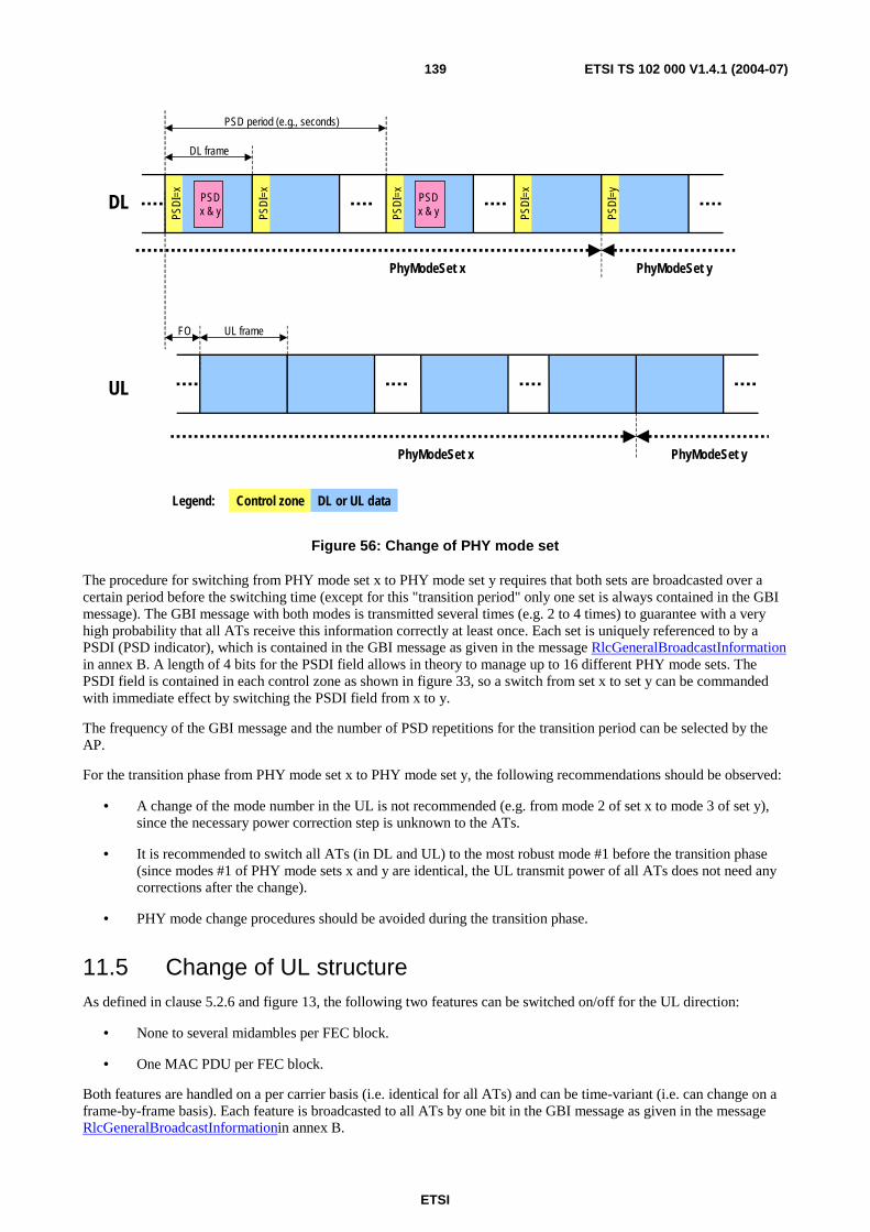
ETSI
ETSI TS 102 000 V1.4.1 (2004-07) 139
PSD
I=x
PSD
I=x
PSD
I=x
PSD
I=x
PSD
I=y
PSDx & y
PSDx & y
PSD period (e.g., seconds)
DL frame
UL frameFO
DL
UL
PhyModeSet x PhyModeSet y
PhyModeSet x PhyModeSet y
Legend: DL or UL dataControl zone
Figure 56: Change of PHY mode set
The procedure for switching from PHY mode set x to PHY mode set y requires that both sets are broadcasted over a certain period before the switching time (except for this "transition period" only one set is always contained in the GBI message). The GBI message with both modes is transmitted several times (e.g. 2 to 4 times) to guarantee with a very high probability that all ATs receive this information correctly at least once. Each set is uniquely referenced to by a PSDI (PSD indicator), which is contained in the GBI message as given in the message RlcGeneralBroadcastInformation in annex B. A length of 4 bits for the PSDI field allows in theory to manage up to 16 different PHY mode sets. The PSDI field is contained in each control zone as shown in figure 33, so a switch from set x to set y can be commanded with immediate effect by switching the PSDI field from x to y.
The frequency of the GBI message and the number of PSD repetitions for the transition period can be selected by the AP.
For the transition phase from PHY mode set x to PHY mode set y, the following recommendations should be observed:
• A change of the mode number in the UL is not recommended (e.g. from mode 2 of set x to mode 3 of set y), since the necessary power correction step is unknown to the ATs.
• It is recommended to switch all ATs (in DL and UL) to the most robust mode #1 before the transition phase (since modes #1 of PHY mode sets x and y are identical, the UL transmit power of all ATs does not need any corrections after the change).
• PHY mode change procedures should be avoided during the transition phase.
11.5 Change of UL structure As defined in clause 5.2.6 and figure 13, the following two features can be switched on/off for the UL direction:
• None to several midambles per FEC block.
• One MAC PDU per FEC block.
Both features are handled on a per carrier basis (i.e. identical for all ATs) and can be time-variant (i.e. can change on a frame-by-frame basis). Each feature is broadcasted to all ATs by one bit in the GBI message as given in the message RlcGeneralBroadcastInformationin annex B.
ETSI
ETSI TS 102 000 V1.4.1 (2004-07) 140
11.6 Load levelling (inter-carrier handover) Load levelling means the switching from one RF channel (i.e. pair of RF carriers for DL and UL communication in case of FDD) to another RF channel, where this shall be initiated by the NMS (Network Management System) or by the AP.
In order to avoid unnecessary complexity, a fast dynamic load levelling procedure is not supported. The PHY layer needs about 100 ms for changing the carrier frequencies, so a seamless load-levelling is not possible (with only one transceiver per AT).
The specified load levelling procedure means basically that an AT shall be switched off from the old RF channel and shall perform a new first initialization procedure on the new RF channel. All parameters settings are commanded and negotiated again, i.e. an information exchange between the two APTs is not required.
The implementation of load levelling is optional for AP and mandatory for AT.
The details of the load levelling procedure are described in annex B for the messages (RlcHandoverCmd, RlcHandoverAck) and diagram 21 with the MSC diagram. The load levelling command RlcHandoverCmd contains a description of the new RF channel (and the AT MAC Address) and no other information. The AT shall reply with the message RlcHandoverAck and then the new APT is informed from the old APT to start the initialization process by issuing the RlcRangingInvitation message. All parameter setting at the AT are cancelled and new established as for a first initialization.
If the message RlcHandoverAck is not received before the expiration of the timer T_HandoverCmd, the AP is recommended to re-transmit the message RlcHandoverCmd. During the duration of T_HandoverAck the AT is waiting for re-transmissions of RlcHandoverCmd (where such a re-transmission is only likely in cases where at least one of the two messages RlcHandoverCmd or RlcHandoverCmd was lost previously).
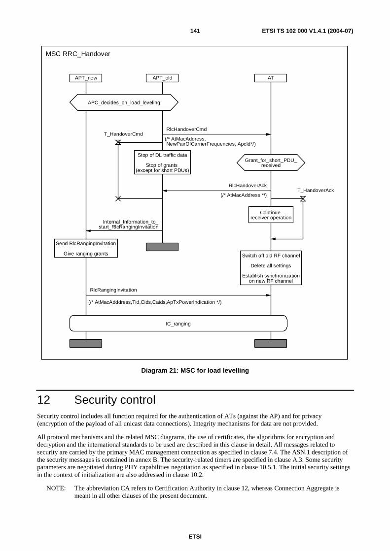
ETSI
ETSI TS 102 000 V1.4.1 (2004-07) 141
APT_new APT_old AT
Grant_for_short_PDU_received
Send RlcRangingInvitation
Give ranging grants Switch off old RF channel
Delete all settings
Establish synchronizationon new RF channel
APC_decides_on_load_leveling
Stop of DL traffic data
Stop of grants (except for short PDUs)
IC_ranging
Continue receiver operation
MSC RRC_Handover
RlcRangingInvitation
(/* AtMacAdddress,Tid,Cids,Caids,ApTxPowerIndication */)
RlcHandoverAck
(/* AtMacAddress */)T_HandoverAck
RlcHandoverCmd
(/* AtMacAddress, NewPairOfCarrierFrequencies, ApcId*/)
T_HandoverCmd
Internal_Information_to_start_RlcRangingInvitation
Diagram 21: MSC for load levelling
12 Security control Security control includes all function required for the authentication of ATs (against the AP) and for privacy (encryption of the payload of all unicast data connections). Integrity mechanisms for data are not provided.
All protocol mechanisms and the related MSC diagrams, the use of certificates, the algorithms for encryption and decryption and the international standards to be used are described in this clause in detail. All messages related to security are carried by the primary MAC management connection as specified in clause 7.4. The ASN.1 description of the security messages is contained in annex B. The security-related timers are specified in clause A.3. Some security parameters are negotiated during PHY capabilities negotiation as specified in clause 10.5.1. The initial security settings in the context of initialization are also addressed in clause 10.2.
NOTE: The abbreviation CA refers to Certification Authority in clause 12, whereas Connection Aggregate is meant in all other clauses of the present document.
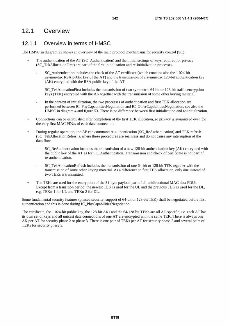
ETSI
ETSI TS 102 000 V1.4.1 (2004-07) 142
12.1 Overview
12.1.1 Overview in terms of HMSC
The HMSC in diagram 22 shows an overview of the main protocol mechanisms for security control (SC).
• The authentication of the AT (SC_Authentication) and the initial settings of keys required for privacy (SC_TekAllocationFirst) are part of the first initialization and re-initialization processes.
- SC_Authentication includes the check of the AT certificate (which contains also the 1 024-bit asymmetric RSA public key of the AT) and the transmission of a symmetric 128-bit authentication key (AK) encrypted with the RSA public key of the AT.
- SC_TekAllocationFirst includes the transmission of two symmetric 64-bit or 128-bit traffic encryption keys (TEK) encrypted with the AK together with the transmission of some other keying material.
- In the context of initialization, the two processes of authentication and first TEK allocation are performed between IC_PhyCapabilitiesNegotiation and IC_OtherCapabilitiesNegotiation, see also the HMSC in diagram 4 and figure 53. There is no difference between first initialization and re-initialization.
• Connections can be established after completion of the first TEK allocation, so privacy is guaranteed even for the very first MAC PDUs of each data connection.
• During regular operation, the AP can command re-authentication (SC_ReAuthentication) and TEK refresh (SC_TekAllocationRefresh), where these procedures are seamless and do not cause any interruption of the data flow.
- SC_ReAuthentication includes the transmission of a new 128-bit authentication key (AK) encrypted with the public key of the AT as for SC_Authentication. Transmission and check of certificate is not part of re-authentication.
- SC_TekAllocationRefresh includes the transmission of one 64-bit or 128-bit TEK together with the transmission of some other keying material. As a difference to first TEK allocation, only one instead of two TEKs is transmitted.
• The TEKs are used for the encryption of the 51-byte payload part of all unidirectional MAC data PDUs. Except from a transition period, the newest TEK is used for the UL and the previous TEK is used for the DL, e.g. TEKn-1 for UL and TEKn-2 for DL.
Some fundamental security features (phased security, support of 64-bit or 128-bit TEK) shall be negotiated before first authentication and this is done during IC_PhyCapabilitiesNegotiation.
The certificate, the 1 024-bit public key, the 128-bit AKs and the 64/128-bit TEKs are all AT-specific, i.e. each AT has its own set of keys and all unicast data connections of one AT are encrypted with the same TEK. There is always one AK per AT for security phase 2 or phase 3. There is one pair of TEKs per AT for security phase 2 and several pairs of TEKs for security phase 3.
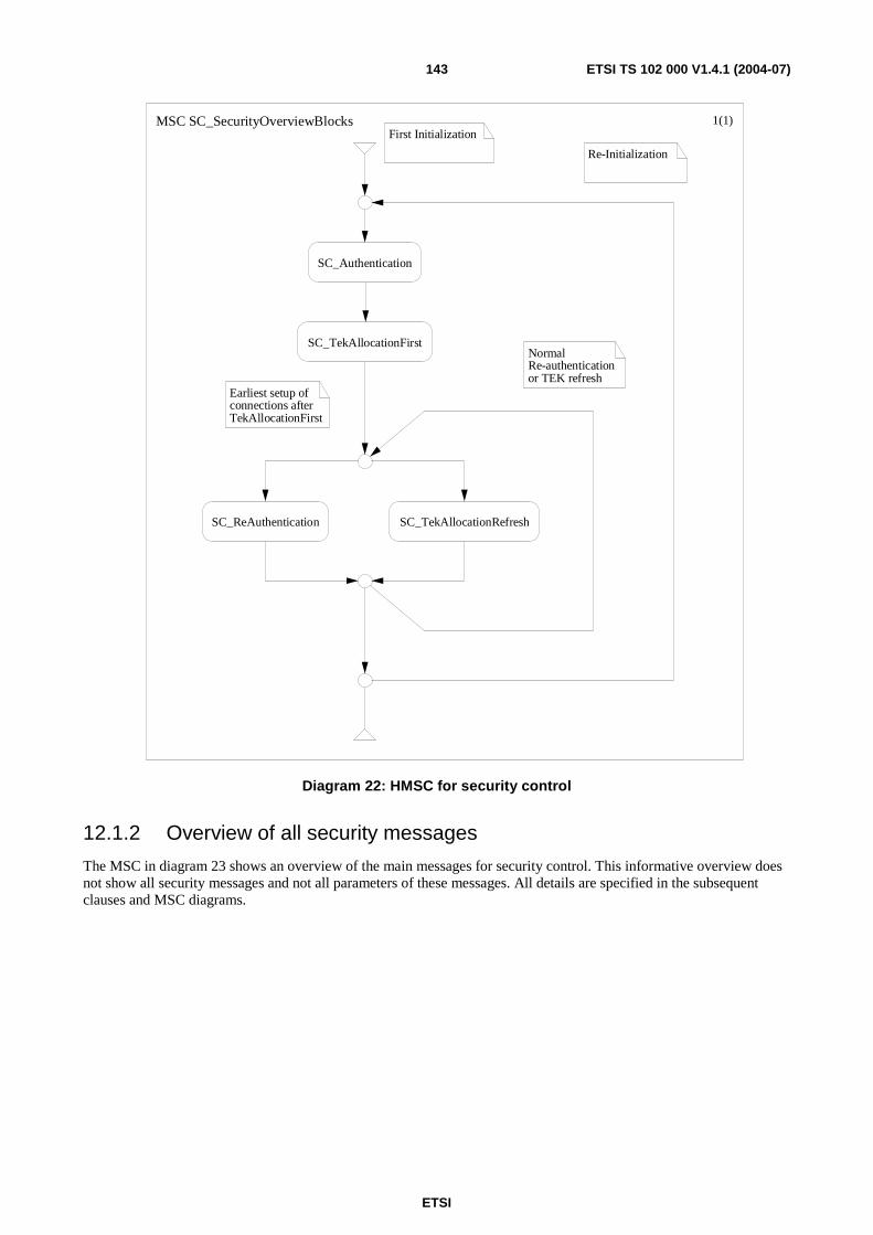
ETSI
ETSI TS 102 000 V1.4.1 (2004-07) 143
First Initialization
Re-Initialization
Normal Re-authenticationor TEK refresh
Earliest setup of connections afterTekAllocationFirst
MSC SC_SecurityOverviewBlocks 1(1)
SC_Authentication
SC_TekAllocationFirst
SC_ReAuthentication SC_TekAllocationRefresh
Diagram 22: HMSC for security control
12.1.2 Overview of all security messages
The MSC in diagram 23 shows an overview of the main messages for security control. This informative overview does not show all security messages and not all parameters of these messages. All details are specified in the subsequent clauses and MSC diagrams.
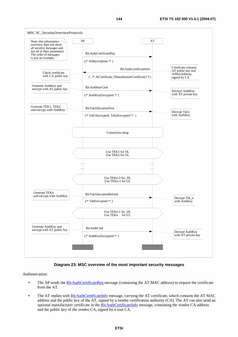
ETSI
ETSI TS 102 000 V1.4.1 (2004-07) 144
AP ATNote: this informativeoverview does not showall security messages and not all of their parameters.The order of messagesis just an example.
Use TEKn-1 for_DLUse TEKn for UL
Use TEKn-2 for_DLUse TEKn-1 for UL
Use TEK1 for DLUse TEK2 for UL
Generate TEKnand encrypt with AuthKey
Decrypt Tek_nwith AuthKey
Generate AuthKey and encrypt with AT public key
Decrypt AuthKeywith AT private key
Generate TEK1, TEK2and encrypt with AuthKey
Check certificatewith CA public key
Generate AuthKey and encrypt with AT public key
Connection setup
Decrypt Tek'swith AuthKey
Certificate containsAT public key andAtMaxAddress,signed by CA
Decrypt AuthKeywith AT private key
MSC SC_SecurityOverviewProtocols
RlcAuthCmd
(/* AuthKeyEncrypted */ )
RlcAuthCertificateInfo
( /* AtCertificate, [ManufacturerCertificate] */)
RlcTekAllocationFirst
(/* Tek1Encrypted, Tek2Encrypted */ )
RlcTekAllocationRefresh
(/* TekEncrypted */ )
RlcAuthCertificateReq
(/* AtMacAddress */ )
RlcAuthKeyCmd
(/* AuthKeyEncrypted */ )
Diagram 23: MSC overview of the most important security messages
Authentication:
• The AP sends the RlcAuthCertificateReq message (containing the AT MAC address) to request the certificate from the AT.
• The AT replies with RlcAuthCertificateInfo message, carrying the AT certificate, which contains the AT MAC address and the public key of the AT, signed by a vendor certification authority (CA). The AT can also send an optional manufacturer certificate in the RlcAuthCertificateInfo message, containing the vendor CA address and the public key of the vendor CA, signed by a root CA.
ETSI
ETSI TS 102 000 V1.4.1 (2004-07) 145
• The certificate is checked in the AP by using the public key of the vendor CA or the public key of the root CA:
- If the certificate is valid, the AP generates a 128-bit AK, encrypts the AK with the public key of the AT and transmits the encrypted AK with the message RlcAuthKeyCmd. The AT decrypts the encrypted AK by using its secret key and replies with the RlcAuthKeyAck message (not shown).
- If the certificate is invalid, the AP sends an RlcAuthReject message (not shown).
First TEK allocation:
• The AP generates two 64/128-bit TEKs (TEK1 and TEK2), two 64-bit initialization vector parameters (IVP) and one 2-bit EKSAllocated parameter, encrypts the TEKs with the AK and transmits all these parameters with the message RlcTekAllocationFirst. The AT decrypts the encrypted TEKs by using its AK and replies with the RlcTekAllocationFirstAck message (not shown).
After setup of one or several connections, TEK2 is used for UL and TEK1 for DL. The AP can now command re-authentications and TEK refreshs, where these two processes shall not be run in parallel.
TEK refresh:
• The AP generates one 64/128-bit TEK (TEKn), one 64-bit IVP and one 2-bit EKSAllocated parameter, encrypts the TEK with the actual AK and transmits all these parameters with the message RlcTekAllocationRefresh. The AT decrypts the encrypted TEK by using its AK and replies with the RlcTekAllocationRefreshAck message (not shown).
Presuppose that TEKn-1 is used for UL and TEKn-2 for DL before the TEK refresh procedure. During the TEK refresh procedure with transmission of TEKn, TEKn-1 is replaced by TEKn for UL and TEKn-2 is replaced by TEKn-1 for DL. The details are specified in clause 12.4.
Re-authentication:
• The AP generates a new 128-bit AK, encrypts the AK with the public key of the AT and transmits the encrypted AK with the message RlcAuthKeyCmd. The AT decrypts the encrypted AK by using its secret key and replies with the RlcAuthKeyAck message (not shown). These messages are identical to those used for first authentication.
All SC-related messages are transmitted with the primary MAC management connection. A summary is contained in clause 7.4.
NOTE: Some security messages (especially RlcAuthCertificateInfo) could be very long and may require the application of SAR (segmentation and re-assembly) for transmission.
12.1.3 Key structure and operational issues
Without counting the asymmetric keys used for the CA, three different key levels shall be distinguished:
• Asymmetric 1 024-bit RSA keys (pairs of public and private keys), used to encrypt the AK.
• Symmetric 128-bit AK, used to encrypt the TEK with the 3DES algorithm.
• Symmetric 64-bit or 128-bit TEK, used to encrypt the 51-byte payload of all unicast MAC data PDUs with the DES or 3DES algorithm.
The encryption of AK with the AT's public key might be time-consuming, however, due to the high-security level provided by the 128-bit key, seldom exchanges of the AK are sufficient. The encryption of TEK with AK does not imply a very high computional burden, so the TEKs can be exchanged more often than the AKs. A frequent TEK exchange is especially recommended in case of 64-bit TEKs.
The exchange periods for AK and TEK are under AP control. Exact values are not specified in the present document. However, an example could be one year for AK and 128-bit TEK and some minutes or hours for 64-bit TEK.
ETSI
ETSI TS 102 000 V1.4.1 (2004-07) 146
12.2 Phased Security
12.2.1 Overview of phase 1, phase 2 and phase 3 security
Phase 1 security is characterized as follows:
• Four fixed TEKs and IVPs are used that are identical for all ATs of a sector.
• The (TEK, IVP) pairs are numbered from 0 to 3 and referenced to by the EKS value of MAC PDU headers.
• The TEK exchange is commanded by the AP for the DL and the AT shall follow as soon as possible for the UL (more details are specified in clause 12.4.6).
• Certificates, asymmetric keys, authentication keys and all cryptographic messages shall be out of use and shall be ignored if received by the other side.
• The distribution of the four (TEK, IVP) pairs is not specified.
Phase 2 security is characterized as follows:
• Full support for certificate check.
• Full support for frequent exchanges of AK and TEK.
• Two AT-specific (TEK, IVP) pairs are used and referenced to by the EKS value of MAC PDU headers. The old TEK is used for DL and the new TEK is used for UL.
Phase 3 security is characterized as follows:
• All features of phase 2 and additionally support of multicast encryption with different TEKs per AT.
Common properties of all phases include:
• Use of 64-bit or 128-bit TEK for the encryption and decryption of the 51-byte MAC PDU payload, including details like CBC mode, padding method, Initialization Vector (IV) generation (see clause 12.5).
• Handling of AT MAC address in the ranging process during initialization.
The support of phase 1 is mandatory for AP and AT, whereas phase 2 or phase 3 is an optional feature for both AP and AT.
Phase 2 is recommended for all applications where no other security functions are provided from outside world. For UMTS backhauling, Phase 1 could be sufficient since encryption for privacy is applied between UMTS terminals and RNC (Radio Network Controller) and so the link between node B and RNC is protected in any case, regardless of wireline or HA-based wireless PMP access solutions.
NOTE: All statements in the present document and especially in clause 12 refer to security phase 2 unless otherwise stated.
12.2.2 Negotiation of phased security
Security according to phase 1 or 2 or 3 is negotiated on a per AT basis in SC_PhyCapabilitiesNegotiation during initialization as follows: The AT informs about its capabilities via the 10-bit NumberSaidSupport field in the RlcPhyCapabilitiesInfo message:
• NumberSaidSupport = 0 means Phase 1.
• NumberSaidSupport = 1 means Phase 2. This means that always the same SAID value in all SC-related and CC-related messages for the same AT shall be used, since the effective handling of several groups of connections with different TEKs for one AT is not specified. The AP shall allocate different SAIDs numbers for different ATs in a sector.
ETSI
ETSI TS 102 000 V1.4.1 (2004-07) 147
• NumberSaidSupport > 1 means Phase 3. One SAID per AT is used for all unicast connections as for phase 2. Several additional SAIDs per AT can be used to encrypt different multicast connections. The AP shall allocate different SAIDs numbers for different ATs in a sector. The same SAID is used for the same multicast connection (i.e. same TEKs for different ATs) and different multicast connection shall have different SAIDs.
The AP commands the phased security via the 3-bit SecurityUse field in RlcPhyCapabilitiesCnf message:
• If AT supports Phase 3, then AP can command
SecurityUse=securityNotUsed (0); or SecurityUse=phaseOne (1); or SecurityUse=phaseTwo (2); or SecurityUse=phaseThree (3).
• If AT supports Phase 2, then AP can command
SecurityUse=securityNotUsed (0); or SecurityUse=phaseOne (1); or SecurityUse=phaseTwo (2).
• If AT supports only Phase 1, then AP can command
SecurityUse=securityNotUsed (0); or SecurityUse=phaseOne (1); or SecurityUse=rejectedFromNetwork (4).
If the AP has the optional capability of supporting phase 2 and the further optional capability of serving ATs with phase 1 and ATs with phase 2 in the same sector, then such a mixed operation is allowed (but it is not mandatory for APs to support such a mixed operation).
In this context two other options are mentioned (which are independent of phase 1 and phase 2):
• The AT informs about its optional support for 128-bit TEKs via the 1-bit TripleDesSupport field in the RlcPhyCapabilitiesInfo message: TripleDesSupport = 0 means no support (64-bit TEK, mandatory); TripleDesSupport = 1 means support (128-bit TEK, optional).
• The AP informs about the use of 128-bit TEKs via the 1-bit TripleDesUse field in the RlcPhyCapabilitiesCnf message: TripleDesUse = 0 means 64-bit TEK; TripleDesUse = 1 means 128-bit TEK.
The AP can switch off encryption on a per sector basis for all ATs via the 1-bit EncryptionMode field in the RlcGeneralBroadcastInformation message (where this parameter shall be constant over time unless all ATs are re-initialized).
12.3 Authentication
12.3.1 Overview
Authentication is based on the fact that the AP shall know the AT MAC address in advance. The AT shall present a certificate which is a secure binding between the MAC address and the RSA public key of the AT, signed by a Certification Authority (CA). This signature is pre-computed in the CA with the secret key of the CA and checked with the public key of the CA in the AP.
Without knowledge of the secret key of the CA, an enemy can not create a valid certificate. Moreover, the certificate creates a secure link between the AT MAC address and the RSA public key of the AT. The AP uses the AT's RSA public key to encrypt the AK and the AT decrypts the AK by using its RSA secret key.
SC_Authentication is the process of requesting, transmitting and checking the certificate together with the transmission of an AK. This process shall be performed during each first initialization and each re-initialization.
SC_ReAuthentication is restricted to the transmission of a new AK with the same messages as for SC_Authentication. The certificates shall not be re-transmitted.

ETSI
ETSI TS 102 000 V1.4.1 (2004-07) 148
12.3.2 First Authentication during first or re-initialization
The MSC for first authentication is shown in diagram 24.
ATAP
no guard timer needed to wait for re-transmission
if HmacOfAuthKeyis invalid
1
1exc
1
1exc
Encrypt Noncewith AuthKey
Decrypt Nonceand check
AuthKey can be used for TEK transmissions
Encrypt AuthKeywith AT public key;Select Nonce randomly
Use same parametersin case of re-transmission
Decrypt AuthKeywith AT private key;Save AuthKey
AP generates AuthKey
AP rejects authentication of ATafter certificate check AT behaviour
depends onErrorCode
Shall be performed atinitialization orre-initialization
MSC SC_Authentication
RlcAuthKeyCmd
(/* AuthKeyEncrypted, HmacOfAuthKey, Nonce */ )
T_AuthKeyCmd
RlcAuthKeyAck
( /* HmacOfNonceEncrypted */)
RlcAuthKeyNack
RlcAuthReject
(/* AuthRejectErrorCode, [ErrorInfoText] */ )
RlcAuthCertificateReq
(/* AtMacAddress, InitializationStatus */ )
RlcAuthCertificateInfo
( /* AtCertificate, [ManufacturerCertificate] */)
T_AuthCertificateReq
Diagram 24: MSC for authentication
The authentication procedure is started with the RlcAuthCertificateReq message, carrying the AT MAC address (to increase the robustness, however, the management CID is sufficient to address the AT) and the InitializationStatus field (informs AT whether IC_OtherCapabilitiesNegotiation will follow or not).
The AT shall transmit the AT certificate and optionally also the vendor certificate (also called manufacturer certificate) in the RlcAuthCertificateInfo message, where all fields shall be transmitted in plaintext. The reception of this message at the AT side is controlled with the T_AuthCertificateReq timer on the AP side.
ETSI
ETSI TS 102 000 V1.4.1 (2004-07) 149
After reception of RlcAuthCertificateInfo, the AP shall stop the timer T_AuthCertificateReq and shall check the certificate with the public key of the CA:
• If the certificate is invalid, the AP shall transmit the message RlcAuthReject.
• If the certificate is valid, the AP shall:
- generates the 128-bit AK, encrypt the AK with the RSA public key of the AT;
- compute the 20-byte message digest field HMAC (Hased Message Authentication Code) of the encrypted AK by using the hash function SHA-1 (the result is called HmacOfAuthKey); and
- generate a 64-bit random number N once.
The AP transmits the encrypted AK, its HMAC and the Nonce in plaintext with the message RlcAuthKeyCmd. The AP shall start the timer T_AuthKeyCmd.
After reception of RlcAuthKeyCmd, the AT shall decrypt the encrypted AK with its RSA private key and check the HMAC. The Nonce is encrypted with AK and hashed to a 20-byte field using the hash function SHA-1 (the result is called HmacOfNonceEncrypted) and transmitted via the RlcAuthKeyAck message to the AP. If the HMAC check of AK at the AT indicates an error, the AT shall transmit the RlcAuthKeyNack message in order to inform the AP about the invalid HMAC.
After reception of RlcAuthKeyAck, the AP shall stop the timer T_AuthKeyCmd and check HMAC of Nonce by using AK. If this check indicates an error, the response of the AP is not specified, however it is recommended the AP re-transmits the RlcAuthKeyCmd message with the same parameters.
In case of time-outs for T_AuthCertificateReq (i.e. expiration of T_AuthCertificateReq without reception of RlcAuthCertificateInfo), the AP is recommended to re-transmit the RlcAuthCertificateReq message with the same parameters. A guard timer after RlcAuthCertificateInfo is not needed, since the AP shall not proceed with the authentication protocol unless the certificate was received and successfully checked.
In case of time-outs for T_AuthKeyCmd (i.e. expiration of T_AuthKeyCmd without reception of RlcAuthKeyAck), it is recommended the AP re-transmits the same AK with the RlcAuthKeyCmd message and the same other parameters. A guard timer after RlcAuthKeyAck is not needed, since the AP shall not use the AK for any purpose unless RlcAuthKeyAck was received and successfully checked.
12.3.3 Re-authentication during normal operation
The MSC for re-authentication is shown in diagram 25.
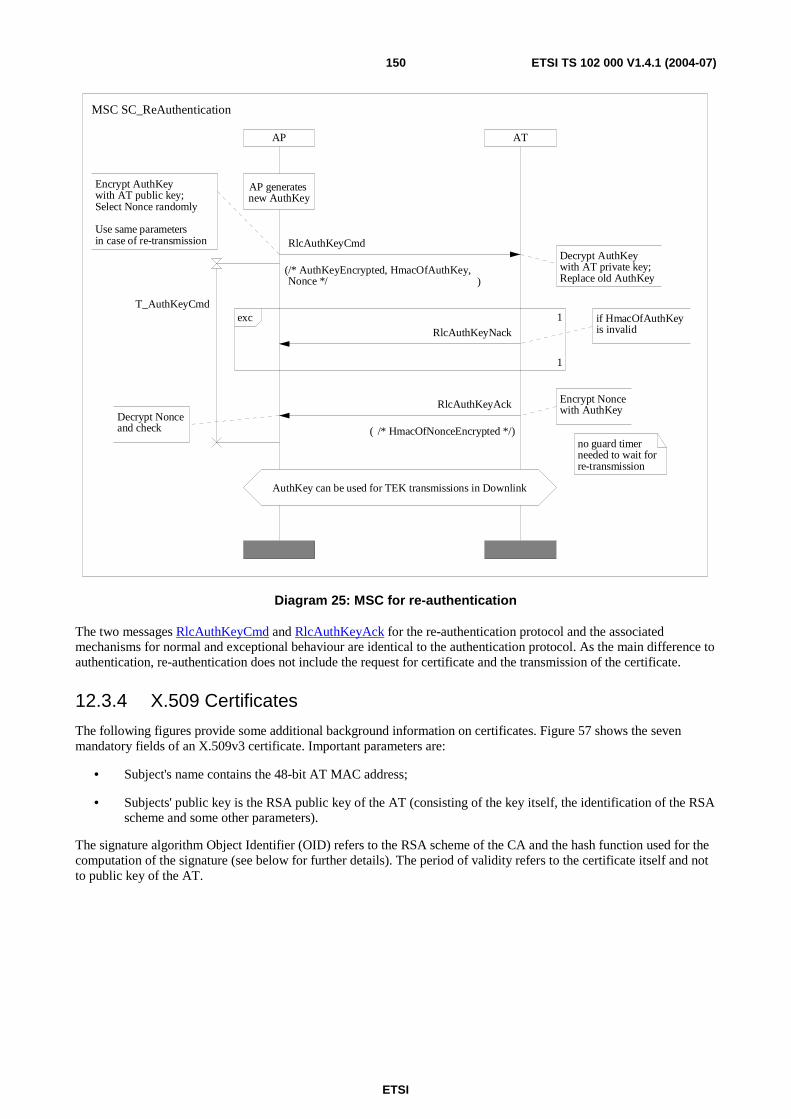
ETSI
ETSI TS 102 000 V1.4.1 (2004-07) 150
ATAP
no guard timer needed to wait for re-transmission
1
1exc
Encrypt Noncewith AuthKey
Decrypt Nonceand check
AuthKey can be used for TEK transmissions in Downlink
Encrypt AuthKeywith AT public key;Select Nonce randomly
Use same parametersin case of re-transmission
if HmacOfAuthKeyis invalid
Decrypt AuthKeywith AT private key;Replace old AuthKey
AP generates new AuthKey
MSC SC_ReAuthentication
T_AuthKeyCmd
RlcAuthKeyAck
( /* HmacOfNonceEncrypted */)
RlcAuthKeyNack
RlcAuthKeyCmd
(/* AuthKeyEncrypted, HmacOfAuthKey,Nonce */ )
Diagram 25: MSC for re-authentication
The two messages RlcAuthKeyCmd and RlcAuthKeyAck for the re-authentication protocol and the associated mechanisms for normal and exceptional behaviour are identical to the authentication protocol. As the main difference to authentication, re-authentication does not include the request for certificate and the transmission of the certificate.
12.3.4 X.509 Certificates
The following figures provide some additional background information on certificates. Figure 57 shows the seven mandatory fields of an X.509v3 certificate. Important parameters are:
• Subject's name contains the 48-bit AT MAC address;
• Subjects' public key is the RSA public key of the AT (consisting of the key itself, the identification of the RSA scheme and some other parameters).
The signature algorithm Object Identifier (OID) refers to the RSA scheme of the CA and the hash function used for the computation of the signature (see below for further details). The period of validity refers to the certificate itself and not to public key of the AT.
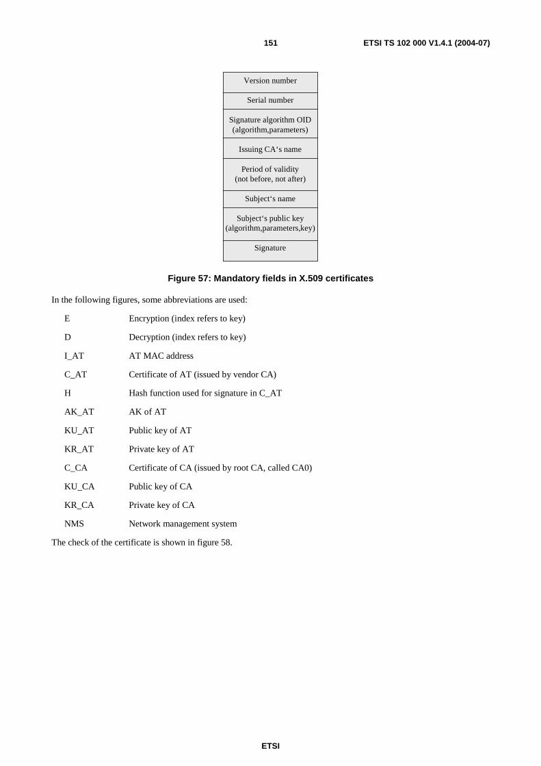
ETSI
ETSI TS 102 000 V1.4.1 (2004-07) 151
Version number
Serial number
Signature algorithm OID(algorithm,parameters)
Issuing CA‘s name
Period of validity(not before, not after)
Subject‘s name
Subject‘s public key(algorithm,parameters,key)
Signature
Figure 57: Mandatory fields in X.509 certificates
In the following figures, some abbreviations are used:
E Encryption (index refers to key)
D Decryption (index refers to key)
I_AT AT MAC address
C_AT Certificate of AT (issued by vendor CA)
H Hash function used for signature in C_AT
AK_AT AK of AT
KU_AT Public key of AT
KR_AT Private key of AT
C_CA Certificate of CA (issued by root CA, called CA0)
KU_CA Public key of CA
KR_CA Private key of CA
NMS Network management system
The check of the certificate is shown in figure 58.
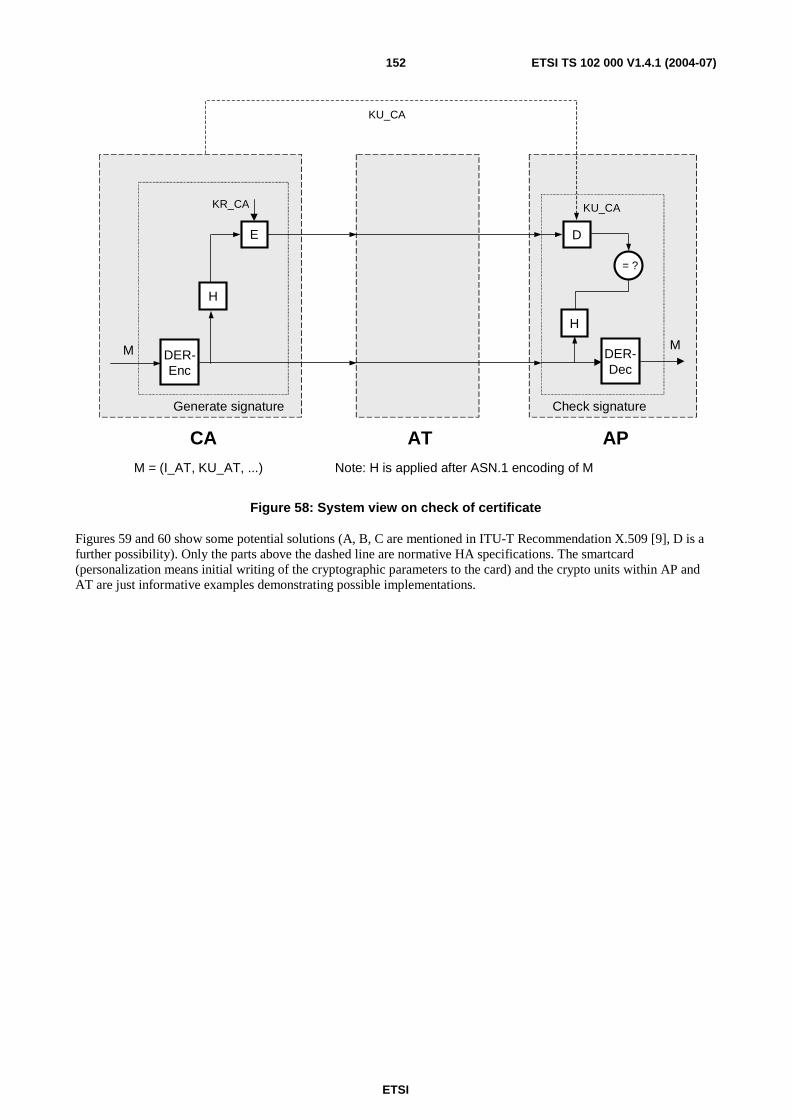
ETSI
ETSI TS 102 000 V1.4.1 (2004-07) 152
H
E D
H
AT
KU_CAKR_CA
= ?
M
AP
Generate signature
CAM = (I_AT, KU_AT, ...) Note: H is applied after ASN.1 encoding of M
Check signature
KU_CA
DER-Enc
DER-Dec
M
Figure 58: System view on check of certificate
Figures 59 and 60 show some potential solutions (A, B, C are mentioned in ITU-T Recommendation X.509 [9], D is a further possibility). Only the parts above the dashed line are normative HA specifications. The smartcard (personalization means initial writing of the cryptographic parameters to the card) and the crypto units within AP and AT are just informative examples demonstrating possible implementations.
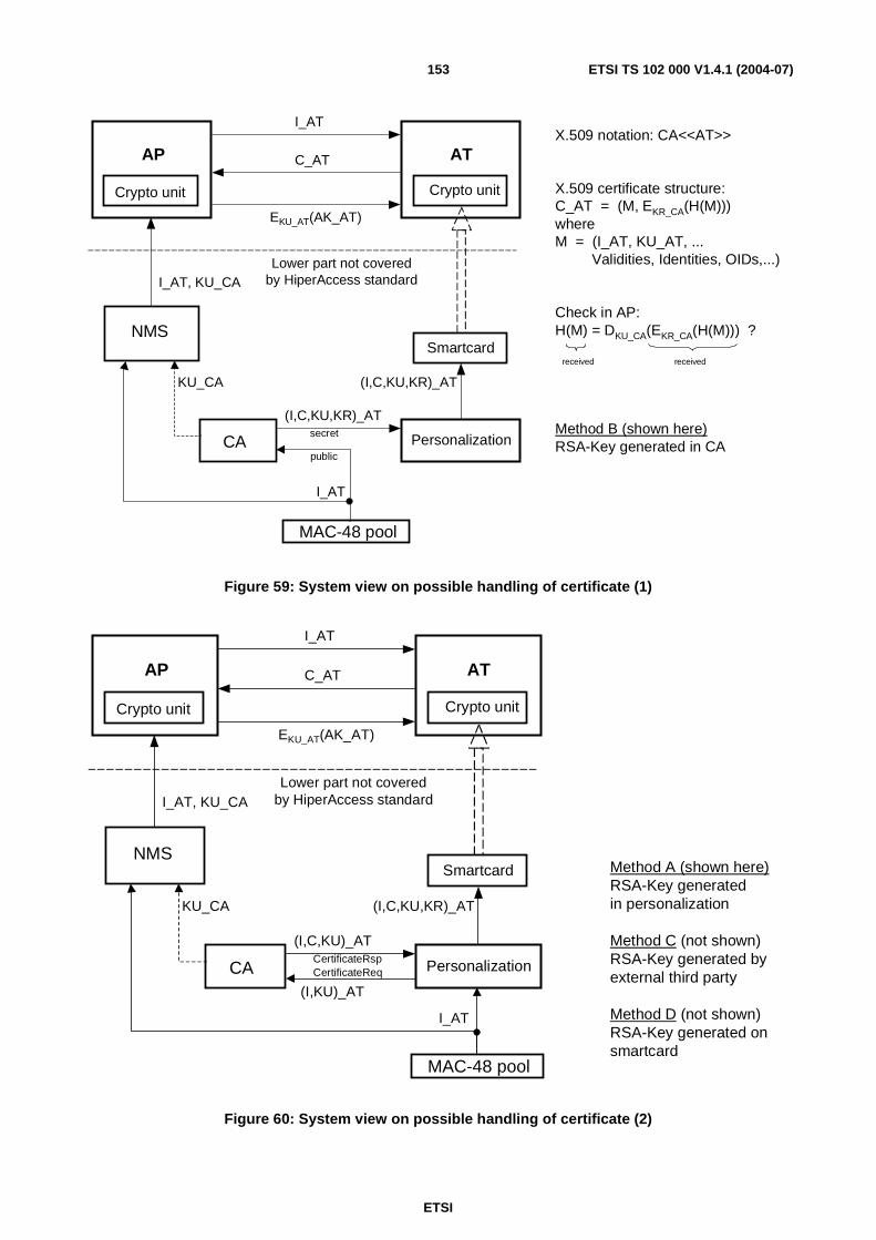
ETSI
ETSI TS 102 000 V1.4.1 (2004-07) 153
X.509 notation: CA<<AT>>
X.509 certificate structure:C_AT = (M, EKR_CA(H(M)))whereM = (I_AT, KU_AT, ... Validities, Identities, OIDs,...)
Check in AP:H(M) = DKU_CA(EKR_CA(H(M))) ?
received received
Method B (shown here)RSA-Key generated in CA
AP AT
Crypto unit Crypto unit
Smartcard
Personalization
NMS
CA
I_AT
C_AT
EKU_AT(AK_AT)
(I,C,KU,KR)_AT
I_AT
(I,C,KU,KR)_AT
I_AT, KU_CA
KU_CA
MAC-48 pool
Lower part not coveredby HiperAccess standard
secret
public
Figure 59: System view on possible handling of certificate (1)
AP AT
Crypto unit Crypto unit
Smartcard
Personalization
NMS
CA
I_AT
C_AT
EKU_AT(AK_AT)
(I,C,KU,KR)_AT
I_AT
(I,C,KU)_AT
I_AT, KU_CA
KU_CA
MAC-48 pool
Lower part not coveredby HiperAccess standard
(I,KU)_AT
Method A (shown here)RSA-Key generatedin personalization
Method C (not shown)RSA-Key generated byexternal third party
Method D (not shown)RSA-Key generated onsmartcard
CertificateRspCertificateReq
Figure 60: System view on possible handling of certificate (2)
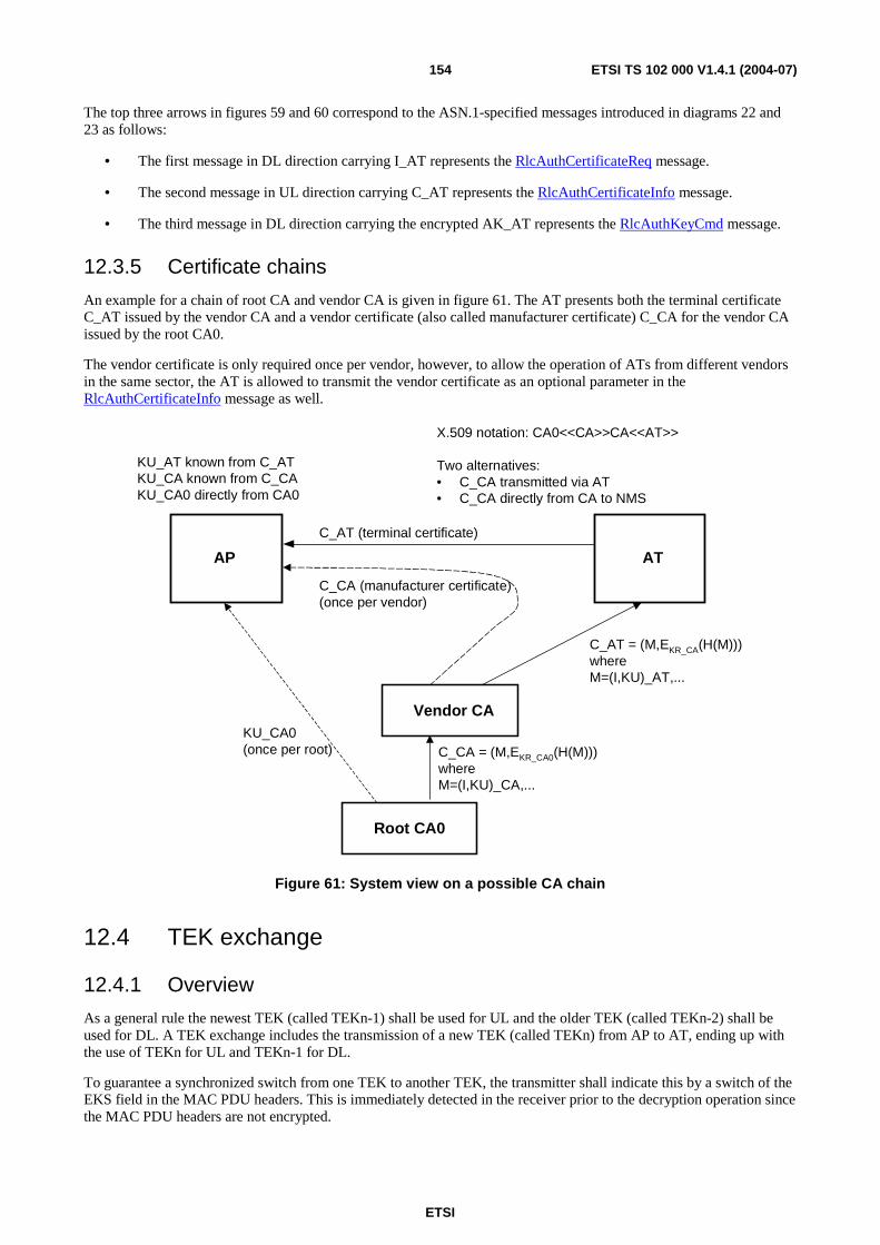
ETSI
ETSI TS 102 000 V1.4.1 (2004-07) 154
The top three arrows in figures 59 and 60 correspond to the ASN.1-specified messages introduced in diagrams 22 and 23 as follows:
• The first message in DL direction carrying I_AT represents the RlcAuthCertificateReq message.
• The second message in UL direction carrying C_AT represents the RlcAuthCertificateInfo message.
• The third message in DL direction carrying the encrypted AK_AT represents the RlcAuthKeyCmd message.
12.3.5 Certificate chains
An example for a chain of root CA and vendor CA is given in figure 61. The AT presents both the terminal certificate C_AT issued by the vendor CA and a vendor certificate (also called manufacturer certificate) C_CA for the vendor CA issued by the root CA0.
The vendor certificate is only required once per vendor, however, to allow the operation of ATs from different vendors in the same sector, the AT is allowed to transmit the vendor certificate as an optional parameter in the RlcAuthCertificateInfo message as well.
AP AT
C_AT (terminal certificate)
Vendor CA
Root CA0
C_AT = (M,EKR_CA(H(M)))whereM=(I,KU)_AT,...
C_CA (manufacturer certificate)(once per vendor)
C_CA = (M,EKR_CA0(H(M)))whereM=(I,KU)_CA,...
KU_CA0(once per root)
KU_AT known from C_ATKU_CA known from C_CAKU_CA0 directly from CA0
X.509 notation: CA0<<CA>>CA<<AT>>
Two alternatives:• C_CA transmitted via AT• C_CA directly from CA to NMS
Figure 61: System view on a possible CA chain
12.4 TEK exchange
12.4.1 Overview
As a general rule the newest TEK (called TEKn-1) shall be used for UL and the older TEK (called TEKn-2) shall be used for DL. A TEK exchange includes the transmission of a new TEK (called TEKn) from AP to AT, ending up with the use of TEKn for UL and TEKn-1 for DL.
To guarantee a synchronized switch from one TEK to another TEK, the transmitter shall indicate this by a switch of the EKS field in the MAC PDU headers. This is immediately detected in the receiver prior to the decryption operation since the MAC PDU headers are not encrypted.
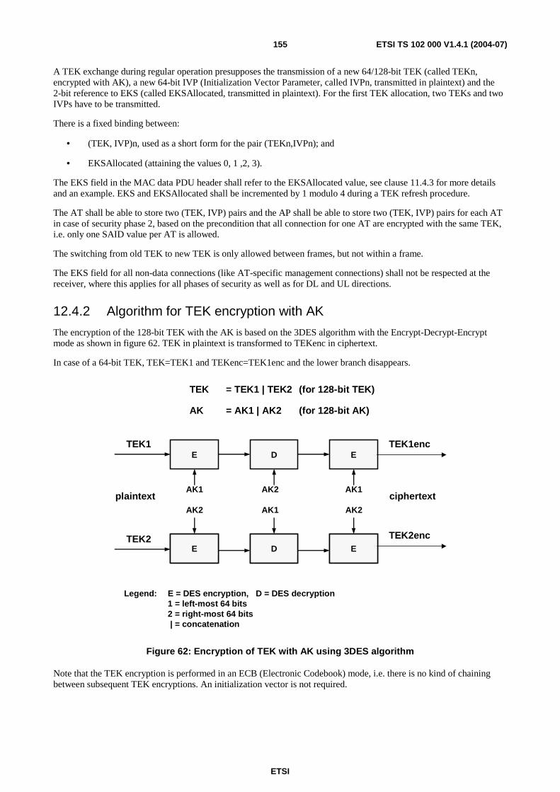
ETSI
ETSI TS 102 000 V1.4.1 (2004-07) 155
A TEK exchange during regular operation presupposes the transmission of a new 64/128-bit TEK (called TEKn, encrypted with AK), a new 64-bit IVP (Initialization Vector Parameter, called IVPn, transmitted in plaintext) and the 2-bit reference to EKS (called EKSAllocated, transmitted in plaintext). For the first TEK allocation, two TEKs and two IVPs have to be transmitted.
There is a fixed binding between:
• (TEK, IVP)n, used as a short form for the pair (TEKn,IVPn); and
• EKSAllocated (attaining the values 0, 1 ,2, 3).
The EKS field in the MAC data PDU header shall refer to the EKSAllocated value, see clause 11.4.3 for more details and an example. EKS and EKSAllocated shall be incremented by 1 modulo 4 during a TEK refresh procedure.
The AT shall be able to store two (TEK, IVP) pairs and the AP shall be able to store two (TEK, IVP) pairs for each AT in case of security phase 2, based on the precondition that all connection for one AT are encrypted with the same TEK, i.e. only one SAID value per AT is allowed.
The switching from old TEK to new TEK is only allowed between frames, but not within a frame.
The EKS field for all non-data connections (like AT-specific management connections) shall not be respected at the receiver, where this applies for all phases of security as well as for DL and UL directions.
12.4.2 Algorithm for TEK encryption with AK
The encryption of the 128-bit TEK with the AK is based on the 3DES algorithm with the Encrypt-Decrypt-Encrypt mode as shown in figure 62. TEK in plaintext is transformed to TEKenc in ciphertext.
In case of a 64-bit TEK, TEK=TEK1 and TEKenc=TEK1enc and the lower branch disappears.
E D E
E D E
plaintextAK1 AK2 AK1
AK2 AK1 AK2
TEK = TEK1 | TEK2 (for 128-bit TEK)
AK = AK1 | AK2 (for 128-bit AK)
TEK1
TEK2
TEK1enc
TEK2enc
ciphertext
Legend: E = DES encryption, D = DES decryption1 = left-most 64 bits2 = right-most 64 bits | = concatenation
Figure 62: Encryption of TEK with AK using 3DES algorithm
Note that the TEK encryption is performed in an ECB (Electronic Codebook) mode, i.e. there is no kind of chaining between subsequent TEK encryptions. An initialization vector is not required.
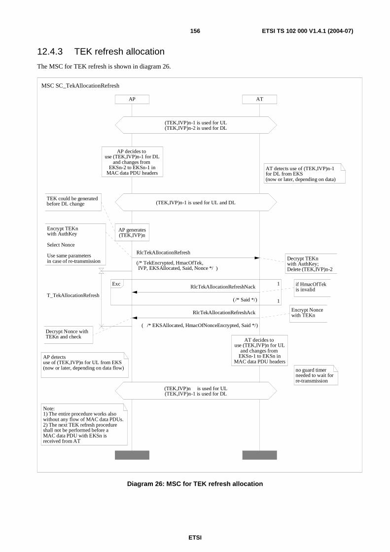
ETSI
ETSI TS 102 000 V1.4.1 (2004-07) 156
12.4.3 TEK refresh allocation
The MSC for TEK refresh is shown in diagram 26.
ATAP
no guard timer needed to wait for re-transmission
AP detects use of (TEK,IVP)n for UL from EKS(now or later, depending on data flow)
Note:1) The entire procedure works alsowithout any flow of MAC data PDUs.2) The next TEK refresh procedure shall not be performed before a MAC data PDU with EKSn is received from AT
AT detects use of (TEK,IVP)n-1 for DL from EKS(now or later, depending on data)
if HmacOfTek is invalid
1
1Exc
Encrypt Nonce with TEKn
Encrypt TEKnwith AuthKey
Select Nonce
Use same parameters in case of re-transmission
Decrypt Nonce with TEKn and check
AT decides to use (TEK,IVP)n for UL
and changes from EKSn-1 to EKSn in
MAC data PDU headers
(TEK,IVP)n is used for UL(TEK,IVP)n-1 is used for DL
Decrypt TEKnwith AuthKey;Delete (TEK,IVP)n-2
TEK could be generatedbefore DL change
AP decides to use (TEK,IVP)n-1 for DL
and changes from EKSn-2 to EKSn-1 in
MAC data PDU headers
AP generates(TEK,IVP)n
(TEK,IVP)n-1 is used for UL and DL
(TEK,IVP)n-1 is used for UL(TEK,IVP)n-2 is used for DL
MSC SC_TekAllocationRefresh
RlcTekAllocationRefreshAck
( /* EKSAllocated, HmacOfNonceEncrypted, Said */)
RlcTekAllocationRefreshNack
( /* Said */)
RlcTekAllocationRefresh
(/* TekEncrypted, HmacOfTek,IVP, EKSAllocated, Said, Nonce */ )
T_TekAllocationRefresh
Diagram 26: MSC for TEK refresh allocation
ETSI
ETSI TS 102 000 V1.4.1 (2004-07) 157
If the AP has decided to exchange the TEK, this shall be performed with the following steps:
• The AP switches from TEKn-2 to TEKn-1 in DL. The AP can delete TEKn-2.
• The AT detects this from the received MAC PDUs (at least later from the following messages in such cases where there is currently no DL data for all connections).
• The AP shall:
- generate (TEK, IVP)n and encrypt TEKn with AK;
- compute a 20-byte HMAC of the encrypted TEK using the hash function SHA-1 (called HmacOfTek); and
- generate a 64-bit random number Nonce.
NOTE 1: All these parameters are transmitted in plain text with the message RlcTekAllocationRefresh. The AP starts the timer T_TekAllocationRefresh.
• After reception of RlcTekAllocationRefresh, the AT decrypts TEKn with AK, checks HMAC of TEK, and can now delete TEKn-2. If the HMAC-check indicates an error, the AT shall reply with the RlcTekAllocationRefreshNack message.
• The AT shall encrypt Nonce with TEKn using the DES mode (for 64-bit TEK) or the 3DES mode (for 128-bit TEK) and transmit the 20-byte field of the hashed encrypted Nonce (by using SHA-1, called HmacOfNonceEncrypted) with the RlcTekAllocationRefreshAck message.
• The AT shall switch from TEKn-1 to TEKn for UL direction.
• After reception of RlcTekAllocationRefreshAck, the AP decrypts the encrypted Nonce and checks the correctness of HMAC. If the check indicates an error, then it is recommended the AP re-transmits the RlcTekAllocationRefresh message with the same parameters.
If the AP receives the RlcTekAllocationRefreshNack message, then the AP is recommended to re-transmit the RlcTekAllocationRefresh message with the same parameters.
In case of time-outs for T_TekAllocationRefresh (i.e. expiration of T_TekAllocationRefresh without reception of RlcTekAllocationRefreshAck), the response of the AP is not specified, however it is recommended the AP re-transmits the same (TEK, IVP)n with the RlcTekAllocationRefresh message using also the same other parameters.. This re-transmission could collide with the AT initiated UL switch from TEKn-1 to TEKn, however, this is uncritical. So, a guard timer after transmission of RlcTekAllocationRefreshAck is not needed.
To avoid problems with overlapping of subsequent TEK exchanges, the next TEK refresh procedure shall not be performed by the AP before at least one MAC data PDU in UL direction using TEKn is received by the AP.
NOTE 2: A wrong TEK on one side could cause catastrophic error propagation, because a fall-back level to detect this is not provided (at least not on the lower layers, this does not exclude possibilities to detect this on higher layers). The reliability of the TEK exchange procedure is extremely high due to the RS error detection capability and the HMAC check of TEK on the AT side and the HMAC check of the encrypted Nonce on the AP side.
Another representation of the TEK refresh procedure is shown in figure 63.
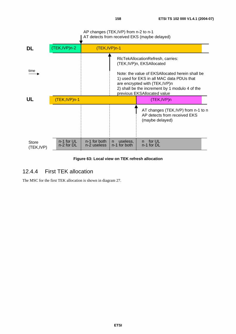
ETSI
ETSI TS 102 000 V1.4.1 (2004-07) 158
(TEK,IVP)n-2 (TEK,IVP)n-1
RlcTekAllocationRefresh, carries:(TEK,IVP)n, EKSAllocated
Note: the value of EKSAllocated herein shall be 1) used for EKS in all MAC data PDUs that are encrypted with (TEK,IVP)n2) shall be the increment by 1 modulo 4 of the previous EKSAllocated value
n-1 for ULn-2 for DL
(TEK,IVP)n
AT changes (TEK,IVP) from n-1 to nAP detects from received EKS (maybe delayed)
n-1 for bothn-2 useless
DL
UL
Store(TEK,IVP)
AP changes (TEK,IVP) from n-2 to n-1 AT detects from received EKS (maybe delayed)
(TEK,IVP)n-1
time
n for ULn-1 for DL
n useless,n-1 for both
Figure 63: Local view on TEK refresh allocation
12.4.4 First TEK allocation
The MSC for the first TEK allocation is shown in diagram 27.

ETSI
ETSI TS 102 000 V1.4.1 (2004-07) 159
Expiration of T_TekAllocationFirstAckdoes not cause retransmissionof RlcTekAllocationFirstAck
AP AT
guard timer shall be stoppedif AT receives RlcTekAllocationFirstTimerStopor AP initiated connection addition.
(TEK,IVP)1 is used for UL(TEK,IVP)2 is used for DL
Setup of connections (for same Said)AP initated setup only after reception ofRlcTekAllocationFirstAck
AT initiated setupif T_TekAllocationFirstAckis not active
1
1exc
if HMAC of TEK1 orHMAC of TEK2 is invalid
Check HMACsEncrypt Nonce with TEK1Encrypt Nonce with TEK2
Encrypt TEK1 with AuthKeyEncrypt TEK2 with AuthKey
Presuppose EKSAllocated2 = 1+EKSAllocated1
Select Nonce
Use same parameters in case of re-transmissions) Delete all old TEKs
(for same Said)Decrypt TEKn with AuthKeyDecrypt TEK2 with AuthKeyCheck Hmac's
AP generates(TEK,IVP)1(TEK,IVP)2
MSC SC_TekAllocationFirst
RlcTekAllocationFirstTimerStop
(/* Said */ )
RlcTekAllocationFirstAck
( /* EKSAllocated1, HmacOfNonceTek1Encrypted, HmacOfNonceTek2Encrypted, Said */)
RlcTekAllocationFirstNack
( /* Said */)
T_TekAllocationFirstAck
RlcTekAllocationFirst
(/* Tek1Encrypted, HmacOfTEK1, IVP1, Tek2Encrypted, HmacOfTEK2, IVP2, EKSAllocated1, Said, Nonce */ )
T_TekAllocationFirst
Diagram 27: MSC for first TEK allocation
The main difference between first TEK allocation and TEK refresh is the fact that two instead of one TEK has to be transmitted. So, the messages RlcTekAllocationFirst and TekAllocationFirstAck have about double length compared to the messages RlcTekAllocationRefresh and TekAllocationRefreshAck.
As an exception from the "double"-principle, only one EKSAllocated value is transmitted: EKSAllocated1 refers to TEK1 and EKSAllocated2 = (1+EKSAllocated1) modulo 4 shall refer to TEK2 by default.
Another representation of the first TEK allocation procedure is shown in figure 64.
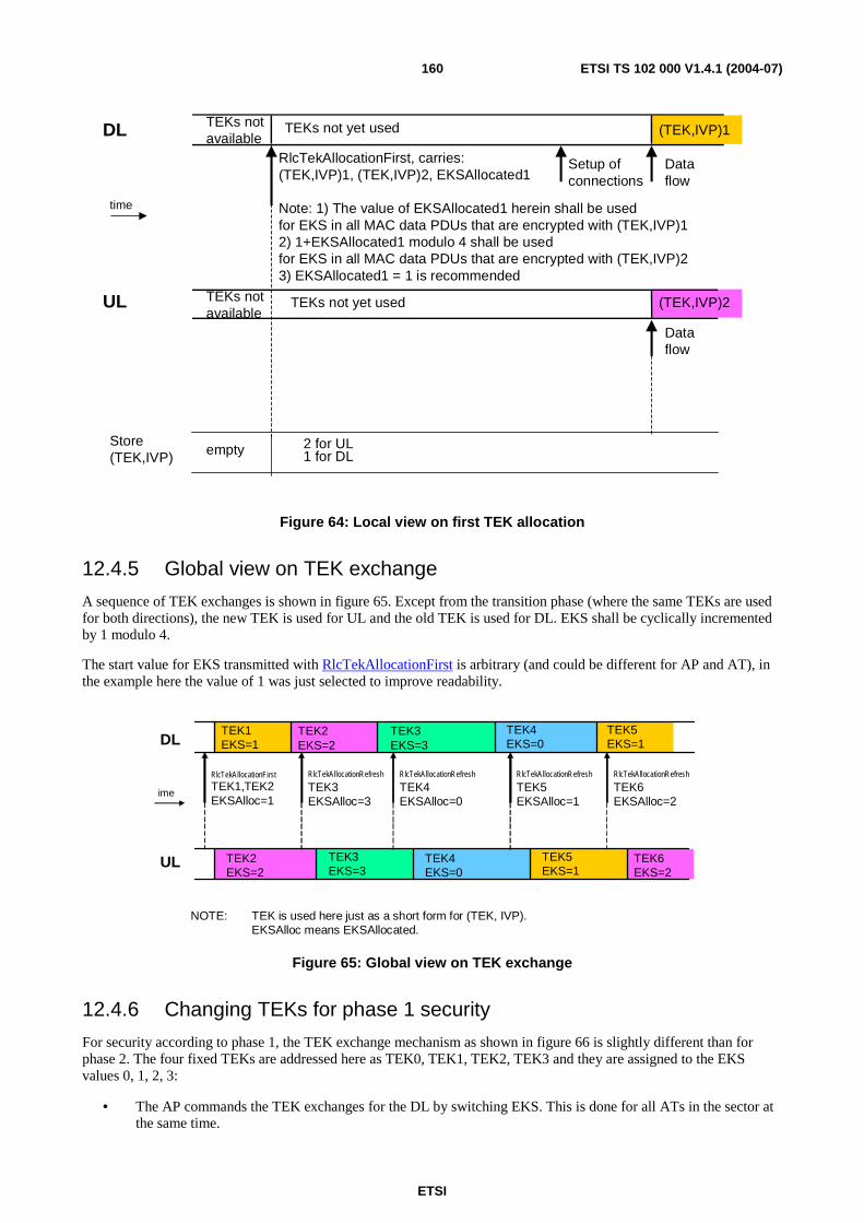
ETSI
ETSI TS 102 000 V1.4.1 (2004-07) 160
(TEK,IVP)1
RlcTekAllocationFirst, carries:(TEK,IVP)1, (TEK,IVP)2, EKSAllocated1
Note: 1) The value of EKSAllocated1 herein shall be used for EKS in all MAC data PDUs that are encrypted with (TEK,IVP)12) 1+EKSAllocated1 modulo 4 shall be used for EKS in all MAC data PDUs that are encrypted with (TEK,IVP)23) EKSAllocated1 = 1 is recommended
empty
(TEK,IVP)2
2 for UL1 for DL
DL
UL
Store(TEK,IVP)
time
TEKs not available
TEKs not yet used
Setup ofconnections
Dataflow
Dataflow
TEKs not available
TEKs not yet used
Figure 64: Local view on first TEK allocation
12.4.5 Global view on TEK exchange
A sequence of TEK exchanges is shown in figure 65. Except from the transition phase (where the same TEKs are used for both directions), the new TEK is used for UL and the old TEK is used for DL. EKS shall be cyclically incremented by 1 modulo 4.
The start value for EKS transmitted with RlcTekAllocationFirst is arbitrary (and could be different for AP and AT), in the example here the value of 1 was just selected to improve readability.
TEK1EKS=1DL
UL
ime
RlcTekAllocationRefresh
TEK3EKSAlloc=3
RlcTekAllocationFirst
TEK1,TEK2EKSAlloc=1
TEK2EKS=2
RlcTekAllocationRefresh
TEK4EKSAlloc=0
RlcTekAllocationRefresh
TEK5EKSAlloc=1
RlcTekAllocationRefresh
TEK6EKSAlloc=2
TEK3EKS=3
TEK4EKS=0
TEK5EKS=1
TEK2EKS=2
TEK3EKS=3
TEK4EKS=0
TEK5EKS=1
TEK6EKS=2
NOTE: TEK is used here just as a short form for (TEK, IVP).EKSAlloc means EKSAllocated.
Figure 65: Global view on TEK exchange
12.4.6 Changing TEKs for phase 1 security
For security according to phase 1, the TEK exchange mechanism as shown in figure 66 is slightly different than for phase 2. The four fixed TEKs are addressed here as TEK0, TEK1, TEK2, TEK3 and they are assigned to the EKS values 0, 1, 2, 3:
• The AP commands the TEK exchanges for the DL by switching EKS. This is done for all ATs in the sector at the same time.
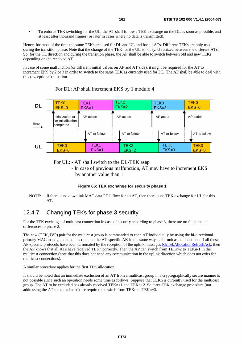
ETSI
ETSI TS 102 000 V1.4.1 (2004-07) 161
• To enforce TEK switching for the UL, the AT shall follow a TEK exchange on the DL as soon as possible, and at least after thousand frames (or later in cases where no data is transmitted).
Hence, for most of the time the same TEKs are used for DL and UL and for all ATs. Different TEKs are only used during the transition phase. Note that the change of the TEK for the UL is not synchronized between the different ATs. So, for the UL direction and during the transition phase, the AP shall be able to switch between old and new TEKs depending on the received AT.
In case of some malfunction (or different initial values on AP and AT side), it might be required for the AT to increment EKS by 2 or 3 in order to switch to the same TEK as currently used for DL. The AP shall be able to deal with this (exceptional) situation.
TEK0EKS=0DL
UL
time
TEK1EKS=1
TEK2EKS=2
TEK3EKS=3
TEK0EKS=0
TEK0EKS=0
TEK1EKS=1
TEK2EKS=2
TEK3EKS=3
TEK0EKS=0
Initialization orRe-Initializationcompleted
AP action AP action AP action AP action
AT to follow AT to follow AT to follow AT to follow
For DL: AP shall increment EKS by 1 modulo 4
For UL: - AT shall switch to the DL-TEK asap - In case of previous malfunction, AT may have to increment EKS by another value than 1
Figure 66: TEK exchange for security phase 1
NOTE: If there is no downlink MAC data PDU flow for an AT, then there is no TEK exchange for UL for this AT.
12.4.7 Changing TEKs for phase 3 security
For the TEK exchange of multicast connection in case of security according to phase 3, there are no fundamental differences to phase 2.
The new (TEK, IVP) pair for the multicast group is commanded to each AT individually by using the bi-directional primary MAC management connection and the AT-specific AK in the same way as for unicast connections. If all these AP-specific protocols have been terminated by the reception of the uplink messages RlcTekAllocationRefreshAck, then the AP knows that all ATs have received TEKn correctly. Then the AP can switch from TEKn-2 to TEKn-1 in the multicast connection (note that this does not need any communication in the uplink direction which does not exits for multicast connections).
A similar procedure applies for the first TEK allocation.
It should be noted that an immediate exclusion of an AT from a multicast group in a cryptographically secure manner is not possible since such an operation needs some time as follows. Suppose that TEKn is currently used for the multicast group. The AT to be excluded has already received TEKn+1 and TEKn+2. So three TEK exchange procedure (not addressing the AT to be excluded) are required to switch from TEKn to TEKn+3.
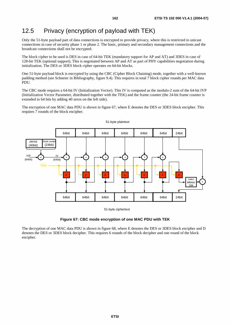
ETSI
ETSI TS 102 000 V1.4.1 (2004-07) 162
12.5 Privacy (encryption of payload with TEK) Only the 51-byte payload part of data connections is encrypted to provide privacy, where this is restricted to unicast connections in case of security phase 1 or phase 2. The basic, primary and secondary management connections and the broadcast connections shall not be encrypted.
The block cipher to be used is DES in case of 64-bit TEK (mandatory support for AP and AT) and 3DES in case of 128-bit TEK (optional support). This is negotiated between AP and AT as part of PHY capabilities negotiation during initialization. The DES or 3DES block cipher operates on 64-bit blocks.
One 51-byte payload block is encrypted by using the CBC (Cipher Block Chaining) mode, together with a well-known padding method (see Schneier in Bibliography, figure 9.4). This requires in total 7 block cipher rounds per MAC data PDU.
The CBC mode requires a 64-bit IV (Initialization Vector). This IV is computed as the modulo-2 sum of the 64-bit IVP (Initialization Vector Parameter, distributed together with the TEK) and the frame counter (the 24-bit frame counter is extended to 64 bits by adding 40 zeros on the left side).
The encryption of one MAC data PDU is shown in figure 67, where E denotes the DES or 3DES block encipher. This requires 7 rounds of the block encipher.
E E E E E E E
+ + + + + + +
64bit 64bit 64bit 64bit 64bit 64bit 24bit
64bit 64bit 64bit 64bit 64bit 64bit 24bit
frame counter
(24bit)zeros(40bit)
TEK
IV(64bit)
51-byte plaintext
51-byte ciphertext
Selectleftmost
24bit+
IVP(64bit)
Figure 67: CBC mode encryption of one MAC PDU with TEK
The decryption of one MAC data PDU is shown in figure 68, where E denotes the DES or 3DES block encipher and D denotes the DES or 3DES block decipher. This requires 6 rounds of the block decipher and one round of the block encipher.
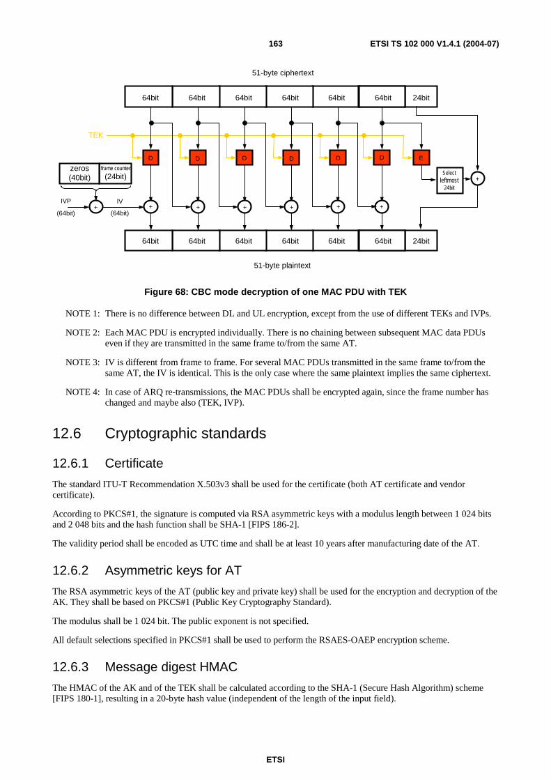
ETSI
ETSI TS 102 000 V1.4.1 (2004-07) 163
D D D D D D E
+ + + + + + +
64bit 64bit 64bit 64bit 64bit 64bit 24bit
frame counter
(24bit)zeros(40bit)
TEK
IVP
(64bit)
IV
(64bit)
51-byte plaintext
51-byte ciphertext
Selectleftmost
24bit
64bit 64bit 64bit 64bit 64bit 64bit 24bit
+
Figure 68: CBC mode decryption of one MAC PDU with TEK
NOTE 1: There is no difference between DL and UL encryption, except from the use of different TEKs and IVPs.
NOTE 2: Each MAC PDU is encrypted individually. There is no chaining between subsequent MAC data PDUs even if they are transmitted in the same frame to/from the same AT.
NOTE 3: IV is different from frame to frame. For several MAC PDUs transmitted in the same frame to/from the same AT, the IV is identical. This is the only case where the same plaintext implies the same ciphertext.
NOTE 4: In case of ARQ re-transmissions, the MAC PDUs shall be encrypted again, since the frame number has changed and maybe also (TEK, IVP).
12.6 Cryptographic standards
12.6.1 Certificate
The standard ITU-T Recommendation X.503v3 shall be used for the certificate (both AT certificate and vendor certificate).
According to PKCS#1, the signature is computed via RSA asymmetric keys with a modulus length between 1 024 bits and 2 048 bits and the hash function shall be SHA-1 [FIPS 186-2].
The validity period shall be encoded as UTC time and shall be at least 10 years after manufacturing date of the AT.
12.6.2 Asymmetric keys for AT
The RSA asymmetric keys of the AT (public key and private key) shall be used for the encryption and decryption of the AK. They shall be based on PKCS#1 (Public Key Cryptography Standard).
The modulus shall be 1 024 bit. The public exponent is not specified.
All default selections specified in PKCS#1 shall be used to perform the RSAES-OAEP encryption scheme.
12.6.3 Message digest HMAC
The HMAC of the AK and of the TEK shall be calculated according to the SHA-1 (Secure Hash Algorithm) scheme [FIPS 180-1], resulting in a 20-byte hash value (independent of the length of the input field).
ETSI
ETSI TS 102 000 V1.4.1 (2004-07) 164
12.6.4 Data encryption standard DES
The CBC mode of DES shall be used according to US Data Encryption Standard algorithm [FIPS 46-3, FIPS 74, FIPS 81] to encrypt the MAC data PDU payload. FIPS 81 defines the effective length of 56-bit DES keys from 64-bit nominal length.
The 3DES operation for TEK encryption with AK is specified in clause 12.4.2. The same block cipher operation shall be used in case of 128-bit TEK for payload encryption.
12.6.5 Random numbers
The generation of random numbers for IVP and Nonce shall be unpredictable. Recommended practices for generating random numbers are provided in RFC 1750 [15].
13 Connection Control (CC) Connections can be created (also called connection establishment, connection addition or connection setup), changed or deleted (also called connection release), where this can be initiated by AP or AT. This shall be accomplished through a series of MAC management messages that are defined in the next clauses together with the procedures for Connection Set-up, Connection Change and Connection Release.
The following rules shall be applied:
• The AP has all necessary knowledge to determine what has to be done at any time as far as the connection establishment or change or deletion procedures are concerned. The AP shall either approve or disapprove all connection management proposals by the AT.
• Either the AP or the AT can initiate a connection termination procedure only in response to the reception of a deletion primitive from the higher layers (except for re-initialization procedures). The connection deletion procedure priority is higher than all other connection control procedures.
When setting a connection the QoS parameters for the MAC PDUs exchanged on the connection itself are implicitly defined.
13.1 Common part layer primitives (informative only) The HA DLC layer supports 18 different service primitives at the DLC Service Access Point. These primitives can be divided up into four different groups according to the related procedure. The complete list is reported in hereafter:
• Connection addition:
- DlcConnectionAdditionInitReq
- DlcConnectionAdditionInitInd
- DlcConnectionAdditionReq
- DlcConnectionAdditionInd
- DlcConnectionAdditionRsp
- DlcConnectionAdditionCnf
• Connection change:
- DlcConnectionChangeInitReq
- DlcConnectionChangeInitInd
- DlcConnectionChangeReq
- DlcConnectionChangeInd
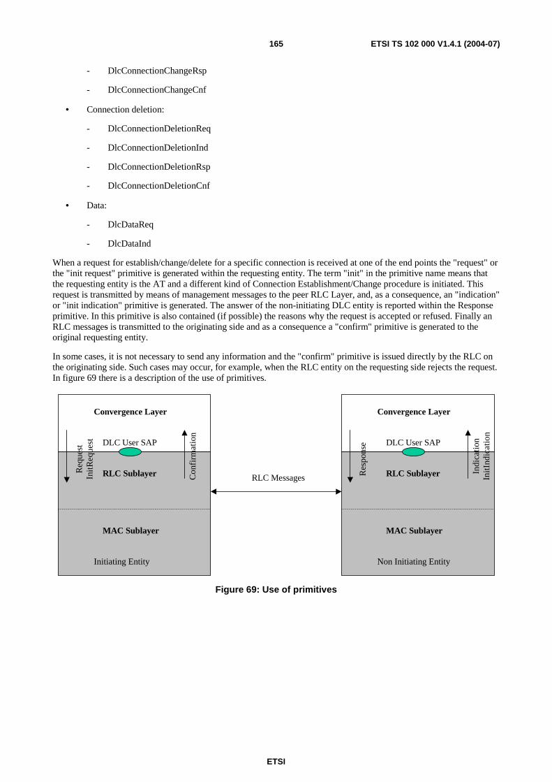
ETSI
ETSI TS 102 000 V1.4.1 (2004-07) 165
- DlcConnectionChangeRsp
- DlcConnectionChangeCnf
• Connection deletion:
- DlcConnectionDeletionReq
- DlcConnectionDeletionInd
- DlcConnectionDeletionRsp
- DlcConnectionDeletionCnf
• Data:
- DlcDataReq
- DlcDataInd
When a request for establish/change/delete for a specific connection is received at one of the end points the "request" or the "init request" primitive is generated within the requesting entity. The term "init" in the primitive name means that the requesting entity is the AT and a different kind of Connection Establishment/Change procedure is initiated. This request is transmitted by means of management messages to the peer RLC Layer, and, as a consequence, an "indication" or "init indication" primitive is generated. The answer of the non-initiating DLC entity is reported within the Response primitive. In this primitive is also contained (if possible) the reasons why the request is accepted or refused. Finally an RLC messages is transmitted to the originating side and as a consequence a "confirm" primitive is generated to the original requesting entity.
In some cases, it is not necessary to send any information and the "confirm" primitive is issued directly by the RLC on the originating side. Such cases may occur, for example, when the RLC entity on the requesting side rejects the request. In figure 69 there is a description of the use of primitives.
RLC Messages
Convergence Layer
DLC User SAP
MAC Sublayer
RLC SublayerReq
uest
Init
Req
uest
Co n
firm
atio
n
Convergence Layer
DLC User SAP
MAC Sublayer
RLC SublayerRe s
pons
e
I ndi
cati
onIn
itInd
icat
i on
Initiating Entity Non Initiating Entity
Figure 69: Use of primitives
ETSI
ETSI TS 102 000 V1.4.1 (2004-07) 166
13.1.1 Use of primitives
In this clause an example of how the primitives and messages are generated and exchanged in case a connection has to be created is given. Two different cases have to be considered:
• The initiating side is the AT: the initiating Convergence Layer entity sends a DlcConnectionAdditionInitReq primitive to the relevant RLC Layer. The initiating side RLC Layer sends the appropriate RlcConnectionAdditionInit message. The non-initiating RLC side generates an "init indication" primitive towards the relevant Convergence Layer and waits for a DlcConnectionAdditionReq primitive. If there is the possibility to establish the requested connection, then an RlcConnectionAdditionSetup message is sent. The initiating side responds to the relevant CL with an "indication" primitive. The reply coming from the upper layer is contained in the DlcConnectionAdditionRsp and as a consequence the RlcConnectionAdditionAck message shall be sent at RLC level. When it is received, a "confirmation" primitive is generated towards the CL of the initiating entity (AT) and this represents the end of the events sequence. At any point along the way, the request may be rejected.
• The initiating side is the AP: the initiating Convergence Layer entity sends a DlcConnectionAdditionReq primitive to the relevant RLC Layer. This causes the sending of an RlcConnectionAdditionSetup message from the initiating side. The non-initiating side issues to the relevant CL an "indication" primitive. The reply coming from the upper layer is contained in the DlcConnectionAdditionRsp and as a consequence the RlcConnectionAdditionAck message shall be sent at RLC level. When it is received, a "confirmation" primitive is generated towards the CL of the initiating entity and this represents the end of the events sequence. At any point along the way, the request may be rejected.
This algorithm is valid also in case of a Connection Change procedure by using the correct messages/primitives.
The DLC layer is never responsible of connection deletion; in case of link failure there will be no notification to the higher layers. The DLC is instead responsible of recovering from the failure unless a specific deletion issue is received from the upper layer.
For Connection Deletion the events sequence is described in diagram 32. If this sequence starts when some of the former procedures for the same connection have not yet been completed, it will overrule the others causing an abortion of the former procedures and the deletion of the connection.
DlcDataReq and DlcDataInd are used during the usual transport of data when the connection the data is exchanged on has already been established.
13.1.2 DlcConnectionAdditionInitReq
When a new connection is to be established, and the initiating entity is the AT then the DlcConnectionAdditionInitReq primitive shall be issued from the Convergence Layer of the generating entity to the relevant RLC Layer.
The parameters contained in the primitive are listed hereafter:
DlcConnectionAdditionInitReq ( Scheduling service type, Convergence Layer ID, Convergence Layer parameters, Encryption indicator, ARQ on/off,Sequence number )
The Convergence Layer (CL) parameter indicates the Convergence Layer that data received on this connection shall refer to. There shall be one specific value for each specific convergence Layer type plus a specific value indicating that no convergence Layer is used.
This CID shall be returned to the requesting convergence Layer via the "confirmation" primitive.
ETSI
ETSI TS 102 000 V1.4.1 (2004-07) 167
13.1.3 DlcConnectionAdditionReq
When a new connection is to be established, and the initiating entity is the AP then the DlcConnectionAdditionReq primitive shall be issued from the Convergence Layer of the generating entity to the relevant RLC Layer.
The parameters contained in the primitive are listed hereafter:
DlcConnectionAdditionReq ( Scheduling service type, Convergence Layer ID, Convergence Layer parameters, Encryption indicator, ARQ on/off, Sequence number )
13.1.4 DlcConnectionAdditionInitInd
The use of this primitive applies to the AT initiating Connection Establishment procedure. The RLC Layer of the AP generates this primitive when it receives an RlcConnectionAdditionInit message from the initiating side at RLC level.
The parameters contained in the primitive are listed hereafter:
DlcConnectionAdditionInd ( Service type, Convergence Layer, Convergence Layer Parameters, Sequence number )
13.1.5 DlcConnectionAdditionInd
The use of this primitive applies to the AP initiating Connection Establishment procedure. The RLC Layer of AT generates this primitive when it receives an RlcConnectionAdditionSetup message from the initiating side at RLC level.
The parameters contained in the primitive are listed hereafter:
DlcConnectionAdditionInd ( Service type, Connection ID, Convergence Layer, Convergence Layer Parameters, Sequence number )
13.1.6 DlcConnectionAdditionRsp
This primitive is generated by the Convergence Layer entity when it has received a DlcConnectionAdditionInd primitive. This event causes the RLC Layer to send the RlcConnectionAdditionAck message.
The parameters contained in the primitive are listed hereafter:
DlcConnectionAdditionRsp ( Response code, Sequence number, ARQ on/off )
The response code indicates success or the reason for rejecting the request.
The sequence number is returned to the requesting entity to correlate this response with the original request.
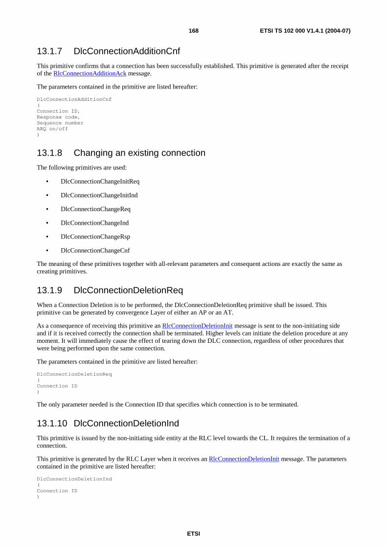
ETSI
ETSI TS 102 000 V1.4.1 (2004-07) 168
13.1.7 DlcConnectionAdditionCnf
This primitive confirms that a connection has been successfully established. This primitive is generated after the receipt of the RlcConnectionAdditionAck message.
The parameters contained in the primitive are listed hereafter:
DlcConnectionAdditionCnf ( Connection ID, Response code, Sequence number ARQ on/off )
13.1.8 Changing an existing connection
The following primitives are used:
• DlcConnectionChangeInitReq
• DlcConnectionChangeInitInd
• DlcConnectionChangeReq
• DlcConnectionChangeInd
• DlcConnectionChangeRsp
• DlcConnectionChangeCnf
The meaning of these primitives together with all-relevant parameters and consequent actions are exactly the same as creating primitives.
13.1.9 DlcConnectionDeletionReq
When a Connection Deletion is to be performed, the DlcConnectionDeletionReq primitive shall be issued. This primitive can be generated by convergence Layer of either an AP or an AT.
As a consequence of receiving this primitive an RlcConnectionDeletionInit message is sent to the non-initiating side and if it is received correctly the connection shall be terminated. Higher levels can initiate the deletion procedure at any moment. It will immediately cause the effect of tearing down the DLC connection, regardless of other procedures that were being performed upon the same connection.
The parameters contained in the primitive are listed hereafter:
DlcConnectionDeletionReq ( Connection ID )
The only parameter needed is the Connection ID that specifies which connection is to be terminated.
13.1.10 DlcConnectionDeletionInd
This primitive is issued by the non-initiating side entity at the RLC level towards the CL. It requires the termination of a connection.
This primitive is generated by the RLC Layer when it receives an RlcConnectionDeletionInit message. The parameters contained in the primitive are listed hereafter:
DlcConnectionDeletionInd ( Connection ID )
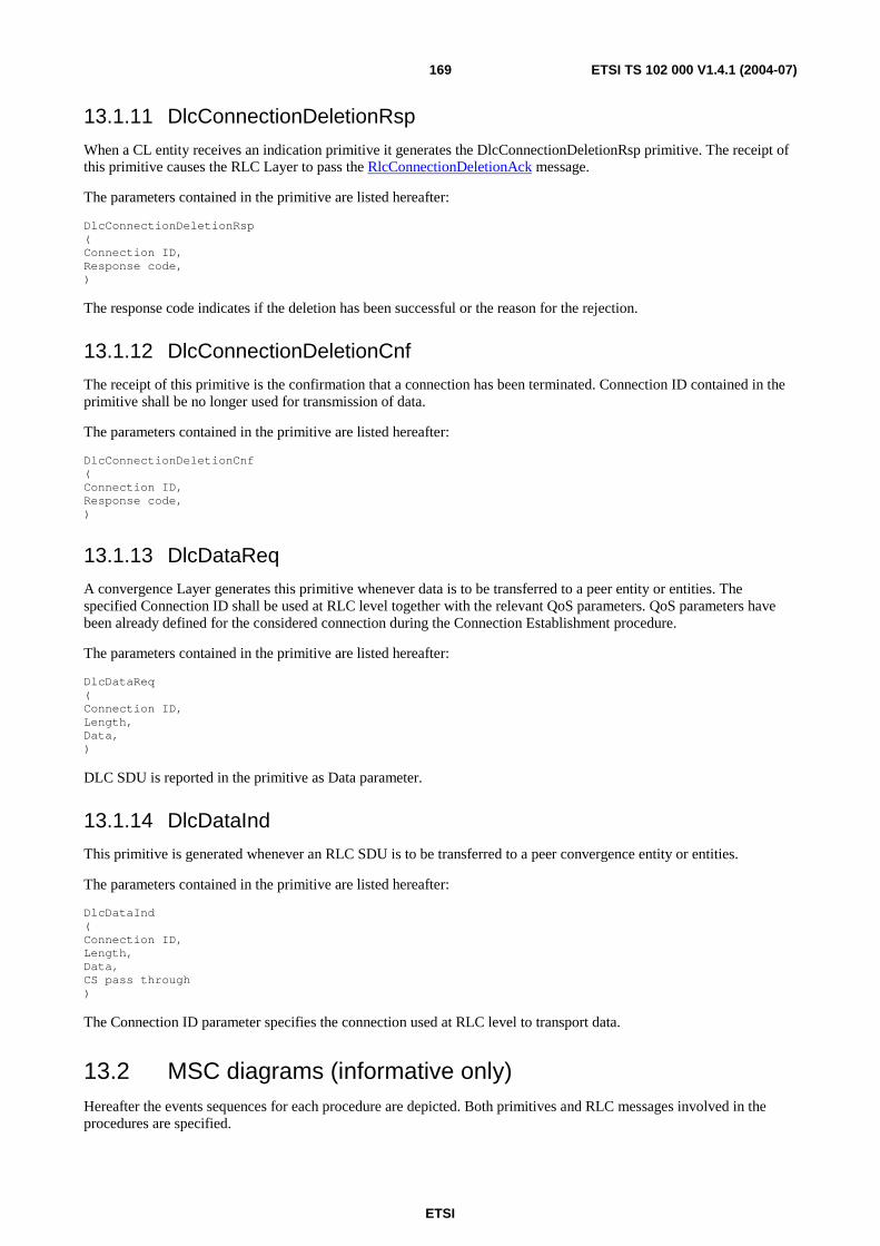
ETSI
ETSI TS 102 000 V1.4.1 (2004-07) 169
13.1.11 DlcConnectionDeletionRsp
When a CL entity receives an indication primitive it generates the DlcConnectionDeletionRsp primitive. The receipt of this primitive causes the RLC Layer to pass the RlcConnectionDeletionAck message.
The parameters contained in the primitive are listed hereafter:
DlcConnectionDeletionRsp ( Connection ID, Response code, )
The response code indicates if the deletion has been successful or the reason for the rejection.
13.1.12 DlcConnectionDeletionCnf
The receipt of this primitive is the confirmation that a connection has been terminated. Connection ID contained in the primitive shall be no longer used for transmission of data.
The parameters contained in the primitive are listed hereafter:
DlcConnectionDeletionCnf ( Connection ID, Response code, )
13.1.13 DlcDataReq
A convergence Layer generates this primitive whenever data is to be transferred to a peer entity or entities. The specified Connection ID shall be used at RLC level together with the relevant QoS parameters. QoS parameters have been already defined for the considered connection during the Connection Establishment procedure.
The parameters contained in the primitive are listed hereafter:
DlcDataReq ( Connection ID, Length, Data, )
DLC SDU is reported in the primitive as Data parameter.
13.1.14 DlcDataInd
This primitive is generated whenever an RLC SDU is to be transferred to a peer convergence entity or entities.
The parameters contained in the primitive are listed hereafter:
DlcDataInd ( Connection ID, Length, Data, CS pass through )
The Connection ID parameter specifies the connection used at RLC level to transport data.
13.2 MSC diagrams (informative only) Hereafter the events sequences for each procedure are depicted. Both primitives and RLC messages involved in the procedures are specified.
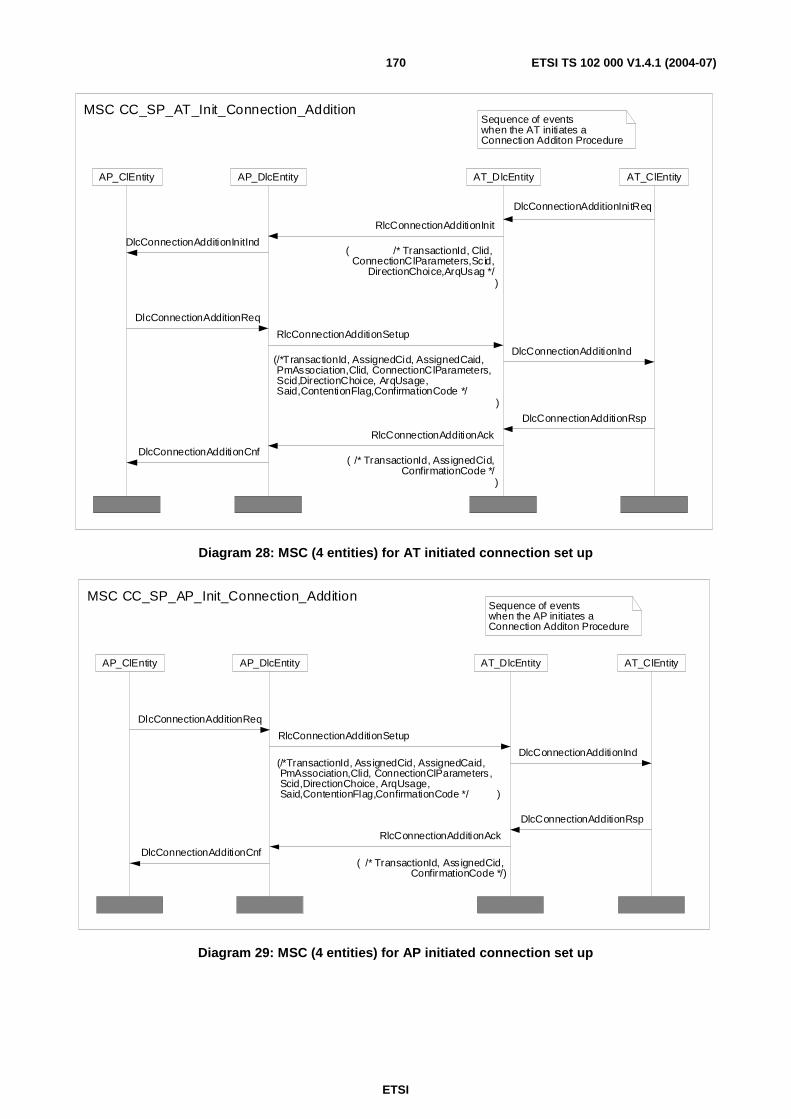
ETSI
ETSI TS 102 000 V1.4.1 (2004-07) 170
AP_DlcEntityAP_ClEntity AT_DlcEntity AT_ClEntity
Sequence of eventswhen the AT initiates a Connection Additon Procedure
MSC CC_SP_AT_Init_Connection_Addition
RlcConnectionAdditionAck
( /* TransactionId, AssignedCid,ConfirmationCode */
)
RlcConnectionAdditionSetup
(/*TransactionId, AssignedCid, AssignedCaid,PmAssociation,Clid, ConnectionClParameters,Scid,DirectionChoice, ArqUsage, Said,ContentionFlag,ConfirmationCode */
)
RlcConnectionAdditionInit
( /* TransactionId, Clid, ConnectionClParameters,Scid,
DirectionChoice,ArqUsag */)
DlcConnectionAdditionCnf
DlcConnectionAdditionReq
DlcConnectionAdditionInitInd
DlcConnectionAdditionInitReq
DlcConnectionAdditionInd
DlcConnectionAdditionRsp
Diagram 28: MSC (4 entities) for AT initiated connection set up
AP_DlcEntityAP_ClEntity AT_DlcEntity AT_ClEntity
Sequence of eventswhen the AP initiates a Connection Additon Procedure
MSC CC_SP_AP_Init_Connection_Addition
RlcConnectionAdditionSetup
(/*TransactionId, AssignedCid, AssignedCaid,PmAssociation,Clid, ConnectionClParameters,Scid,DirectionChoice, ArqUsage, Said,ContentionFlag,ConfirmationCode */ )
RlcConnectionAdditionAck
( /* TransactionId, AssignedCid,ConfirmationCode */)
DlcConnectionAdditionReq
DlcConnectionAdditionCnf
DlcConnectionAdditionInd
DlcConnectionAdditionRsp
Diagram 29: MSC (4 entities) for AP initiated connection set up
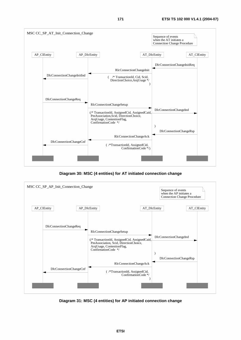
ETSI
ETSI TS 102 000 V1.4.1 (2004-07) 171
AT_ClEntityAT_DlcEntityAP_DlcEntityAP_ClEntity
Sequence of eventswhen the AT initiates a Connection Change Procedure
MSC CC_SP_AT_Init_Connection_Change
RlcConnectionChangeSetup
(/* TransactionId, AssignedCid, AssignedCaid, PmAssociation,Scid, DirectionChoice, ArqUsage, ContentionFlag, ConfirmationCode */
)
RlcConnectionChangeAck
( /*TransactionId, AssignedCid, ConfirmationCode */)
RlcConnectionChangeInit
( /* TransactionId, Cid, Scid, DirectionChoice,ArqUsage */
)
DlcConnectionChangeInitInd
DlcConnectionChangeInitReq
DlcConnectionChangeCnf
DlcConnectionChangeRsp
DlcConnectionChangeInd
DlcConnectionChangeReq
Diagram 30: MSC (4 entities) for AT initiated connection change
Sequence of eventswhen the AP initiates a Connection Change Procedure
AT_DlcEntityAP_DlcEntityAP_ClEntity AT_ClEntity
MSC CC_SP_AP_Init_Connection_Change
RlcConnectionChangeSetup
(/* TransactionId, AssignedCid, AssignedCaid, PmAssociation, Scid, DirectionChoice, ArqUsage, ContentionFlag, ConfirmationCode */
)
RlcConnectionChangeAck
( /*TransactionId, AssignedCid, ConfirmationCode */
)
DlcConnectionChangeCnf
DlcConnectionChangeRsp
DlcConnectionChangeInd
DlcConnectionChangeReq
Diagram 31: MSC (4 entities) for AP initiated connection change
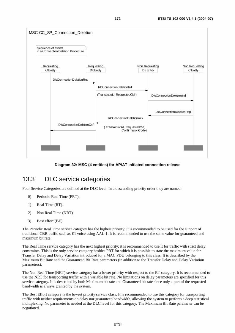
ETSI
ETSI TS 102 000 V1.4.1 (2004-07) 172
ClEntityNon Requesting
DlcEntityNon Requesting
DlcEntityRequesting
ClEntityRequesting
Sequence of eventsin a Connection Deletion Procedure
MSC CC_SP_Connection_Deletion
DlcConnectionDeletionReq
DlcConnectionDeletionCnf
RlcConnectionDeletionAck
( TransactionId, RequestedCid, ConfirmationCode)
DlcConnectionDeletionRsp
DlcConnectionDeletionInd
RlcConnectionDeletionInit
(TransactioId, RequestedCid )
Diagram 32: MSC (4 entities) for AP/AT initiated connection release
13.3 DLC service categories Four Service Categories are defined at the DLC level. In a descending priority order they are named:
0) Periodic Real Time (PRT).
1) Real Time (RT).
2) Non Real Time (NRT).
3) Best effort (BE).
The Periodic Real Time service category has the highest priority; it is recommended to be used for the support of traditional CBR traffic such as E1 voice using AAL-1. It is recommended to use the same value for guaranteed and maximum bit rate.
The Real Time service category has the next highest priority; it is recommended to use it for traffic with strict delay constraints. This is the only service category besides PRT for which it is possible to state the maximum value for Transfer Delay and Delay Variation introduced for a MAC PDU belonging to this class. It is described by the Maximum Bit Rate and the Guaranteed Bit Rate parameters (in addition to the Transfer Delay and Delay Variation parameters).
The Non Real Time (NRT) service category has a lower priority with respect to the RT category. It is recommended to use the NRT for transporting traffic with a variable bit rate. No limitations on delay parameters are specified for this service category. It is described by both Maximum bit rate and Guaranteed bit rate since only a part of the requested bandwidth is always granted by the system.
The Best Effort category is the lowest priority service class. It is recommended to use this category for transporting traffic with neither requirements on delay nor guaranteed bandwidth, allowing the system to perform a deep statistical multiplexing. No parameter is needed at the DLC level for this category. The Maximum Bit Rate parameter can be negotiated.
ETSI
ETSI TS 102 000 V1.4.1 (2004-07) 173
In order to achieve the service related to each Service Category listed above the following parameters shall be configured during the connection establishing phase:
• Guaranteed bit rate: it is the guaranteed rate for the connection (it can be used or not by the connection, but, if requested, it is always available).
• Maximum bit rate: it is the maximum rate allowed for the connection.
• Maximum Burst Length: it is the maximum number of consecutive MAC PDUs that a connection is allowed to transmit.
• Transfer Delay: it is the maximum delay that a PDU may experience in passing through the system.
13.4 Connection control procedures In the following clauses the procedures for connection set-up, connection Change and connection deletion are described.
Guard timers are needed on both sides to make the procedures able to recover from the loss of messages. Possible error scenarios are analyzed within the relevant clauses.
The guard timers are specified in clause A.4.
Guard timers defined in the CC procedures shall be divided into two different categories:
• Short timers: the duration of the Short timer shall be set to the value of 500 ms.
• Medium timers: the duration of the Medium timer shall be set to 6 × (Short timers).
Guard timers belonging to the Short category are:
• T_ConnectionAdditionInit
• T_ConnectionAdditionSetup
• T_ConnectionChangeInit
• T_ConnectionChangeSetup
• T_ConnectionDeletionInit
Guard timers belonging to the Medium category are:
• T_ConnectionAdditionAck
• T_ConnectionChangeAck
• T_ConnectionDeletionAck
The meaning of all these timers is described in the following clauses.
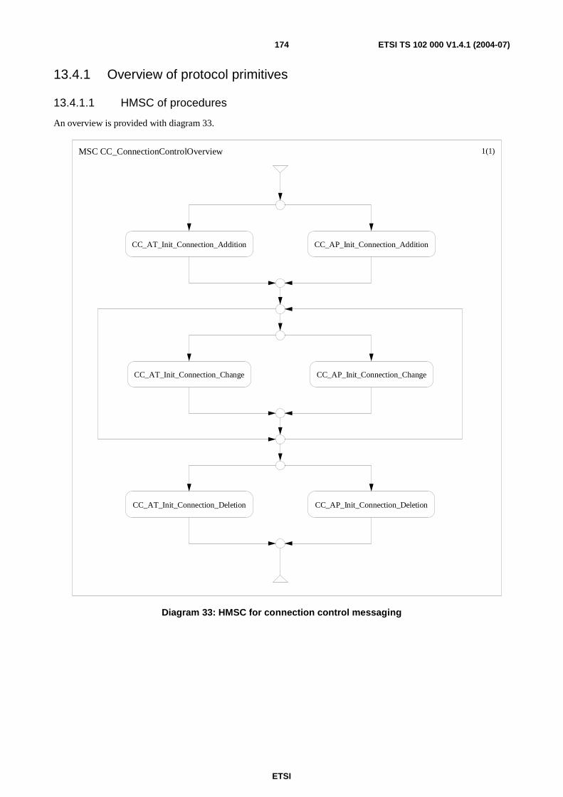
ETSI
ETSI TS 102 000 V1.4.1 (2004-07) 174
13.4.1 Overview of protocol primitives
13.4.1.1 HMSC of procedures
An overview is provided with diagram 33.
MSC CC_ConnectionControlOverview 1(1)
CC_AT_Init_Connection_Addition CC_AP_Init_Connection_Addition
CC_AP_Init_Connection_ChangeCC_AT_Init_Connection_Change
CC_AP_Init_Connection_DeletionCC_AT_Init_Connection_Deletion
Diagram 33: HMSC for connection control messaging
ETSI
ETSI TS 102 000 V1.4.1 (2004-07) 175
13.4.1.2 Parameters
All parameters to be communicated during the three procedures are relevant only to the data connections. Management connections are defined at the first initialization phase and have specific characteristics and parameters. The list of parameters is reported hereafter:
• Connection Aggregate ID: Connection Aggregate ID (Caid) defines the way connections are considered at the AP side during their activity. The single connection is visible at the AP only at establishment, change and deletion operations. During the connection lifetime, they are handled only as part of the Connection Aggregate they belong to. The maximum number of possible CAs that the AP can establish with the same AT is negotiated in the initialization procedure.
• Poll-me bit association: This parameter associates, or not, the connection aggregate ID specified in the previous field with the poll-me bit usage. The poll-me bit association shall have the same value for all the connections within the same connection aggregate.
• Transaction ID: A Transaction ID is associated to each procedure by the initiating device (AP or AT). To help pre-vent ambiguity and provide simple checking, the Transaction ID number space is split between the AT and AP. In this case the AT shall select its Transaction IDs from the first half of the number space and the AP shall select its Transaction IDs from the second half of the number space. The transactions may consist of a request/response/confirmation or a setup/confirmation sequence. The response and confirmation messages shall return a confirmation code specifying whether the transaction had a positive ending or some exception condition was detected.
• Service Category Identifier (ScId): Identifier of the DLC service category.
• Contention Flag: For an uplink connection this parameter indicates if the AT is allowed to issue contention requests for bandwidth.
• Convergence Layer Identifier (ClId): This parameter identifies the convergence layer the connection belongs to.
• Convergence Layer Parameters (ConnectionClParameters): This parameter contains information used by the convergence layer. It is transported transparently by the DLC layer that passes this parameter to the higher layer. The format is a string octet of variable length. Each CL specification defines how this parameter is used.
• Security Association Identifier (SaId): This parameter shall be carried in Downlink direction only and indicates the association between the connection and the security association.
• ARQ Usage: This parameter indicates the ARQ functionality for the connection. The possible options are the following (the value 0 means that the function is disabled):
- No ARQ (0);
- Once ARQ (1).
• Direction Choice: This parameter describes the characteristics of the data flow. It can assume 4 different forms depending on the direction of the transported data flow and if the data rate is symmetrical or not. Specifically:
- Uplink Direction;
- Downlink Direction;
- Bi-directional Symmetrical;
- Bi-directional Asymmetrical.
In the first three cases the description contains only one entry, while in the last case two entries are needed. Each entry is composed by a list of parameters that characterize the connection:
• Guaranteed bit rate: In the Real Time and Non Real Time service categories, this parameter means the amount of bandwidth that the system reserves to the connection. Its granularity is 1 kbit/s so that the maximum flexibility is achieved.

ETSI
ETSI TS 102 000 V1.4.1 (2004-07) 176
• Maximum bit rate: This parameter means the maximum load that the system can receive from the connection. It is mandatory for Real Time and Non Real Time service categories, while for the Best Effort traffic it can be an informative field. Its granularity is 1 kbit/s.
• ConnectionMinPhyMode: For both Uplink and Downlink direction, this parameter indicates the most robust Phy Mode in which the AT has to consider the connection as active. If set to the lowest PHY mode, this parameter has no effect on connection handling. The minimum PHY mode shall be the same for all connections of a connection aggregate.
13.4.2 Connection establishment procedure
The DLC layer is connection-oriented and connection may be provisioned when one of the end points requires a new data flow to be transported or a subscriber needs to change its service parameters.
A connection can be established within the first initialization phase, in a pre-provisioned way or dynamically created.
Pre-provisioned connections are defined via provisioning by the network management system. The AP can be requested to establish a connection by specifying CID and the associated QoS parameters set.
The CID is always assigned by the AP. The APC shall not assign the same CID to more than one connection per RF channel. In case of bi-directional connections, either symmetric or asymmetric, only one CID is assigned and it identifies the connection in both directions.
Dynamic connections are created via signalling exchange at any time by the AP or by an already signed-on AT. In the dynamic connections establishment, both the AP and the AT can request to create an Uplink, Downlink or bi-directional connection.
The procedure can be initiated by either the AP or the AT and can create only one Uplink, Downlink or bi-directional connection. Once it has been established, a connection can be modified with the Change procedure, by changing the parameter sets of the flow. Regardless the initiating entity the connection can be:
• Downlink connection: the data flow that is transported by the considered connection flows in Downlink direction only.
• Uplink connection: the data flow that is transported by the considered connection flows in Uplink direction only.
• Bi-directional Symmetric connection: the connection transports data flows both in Uplink and in Downlink directions and the bit rate is symmetric (the same for the Uplink and the Downlink).
• Bi-directional Asymmetric connection: the connection transports data flows both in Uplink and in Downlink directions and the bit rate is Asymmetric (different values for the Uplink or the Downlink).
Once established, a bi-directional connection cannot be deleted in one way only. A bi-directional symmetric connection can be changed in a bi-directional asymmetric connection by means of a connection change procedure and vice-versa. Either the Uplink or Downlink set of parameter belonging to a specific asymmetric bi-directional connection can be changed independently.
The algorithms for connection Establishment are (depending on the generating point):
• AT initiated (only dynamic connections): Three-way handshaking.
• AP initiated: Two-way handshaking.
The three-way handshaking is needed in the former case because when the AT requires a new connection, it is not aware of the traffic load and can only request the AP to establish a connection with the proposed set of QoS parameters.
If one of the requested QoS parameters exceeds some relevant limitations then the connection cannot be established/changed and a new set of values for the parameters shall be defined.

ETSI
ETSI TS 102 000 V1.4.1 (2004-07) 177
The AP may decide to group connections into Connection Aggregates according to its allocation mechanisms. The rules on grouping connections into CAs are:
• Connection Aggregates cannot be defined among different ATs in Uplink direction.
• Connections belonging to different QoS classes should not be grouped into the same connection aggregate.
• When a connection is added to an aggregate the set of parameter of the aggregate shall be updated.
• QoS info are required for grouping to CA (or for setup of new CA) and thus for choice of appropriate allocation mechanism.
13.4.2.1 AT initiated connection establishment procedure
The algorithm used for connection Establishment when initiated by the AT is based on the Three-way handshaking. The AT will request the AP for a connection with the RlcConnectionAdditionInit message. If there are available resources and the AT has no basic limitations, the AP will send an RlcConnectionAdditionSetup message with all relevant information to the AT. The AP shall be ready to send and receive data on the connection when it transmits the RlcConnectionAdditionSetup message and may grant UL bandwidth for the connection. The AT will confirm with an RlcConnectionAdditionAck message. The AP will not be allowed to transmit any data traffic on the connection before confirmation is received. When the AT sends the RlcConnection AdditionAck message it shall be ready to receive data on the connection and may start transmitting UL data on the connection if conditions (bandwidth granted, data available, etc.) are met. Once the AP receives the RlcConnectionAdditionAck, it may start transmitting DL data on the connection.
In the RlcConnectionAdditionInit message, the AT proposes values of the QoS parameters, but these values are decided by the AP and sent in the RlcConnectionAdditionSetup message.
Guard timers are needed on both sides to make the procedure able to recover from the loss of messages. In particular three situations need to be handled by the use of timers during the Establishment procedure initialized by the AT.
The first case happens at the AT side in order to re-send the RlcConnectionAdditionInit message. This timer is named T_ConnectionAdditionInit. When this timer expires and the RlcConnectionAdditionSetup message is not received by the AT, the RlcConnectionAdditionInit message is re-sent. This timer is reset when the RlcConnectionAdditionSetup is received.
The second timer needed is the T_ConnectionAdditionSetup timer. It is defined at the AP side. This timer is reset when the RlcConnectionAdditionAck is received. If it expires without any reception of the RlcConnectionAdditionAck message, then the RlcConnectionAdditionSetup message is re-sent.
Finally a T_ConnectionAdditionAck timer is needed on both sides. This because expiration of other timers can cause race conditions where a message is re-sent the same frame as the reply that would reset the timer. Socare must be taken not to release the Transaction ID for reuse too early. When the one at AT side expires, the AT can be certain that the AP has received the RlcConnectionAdditionAck, so the AT no longer needs to be prepared to resend it and the Transaction ID may be reused. At AP side after the AP has received the RlcConnectionAdditionAck message the T_ConnectionAdditionSetup is reset and the T_ConnectionAdditionAck is started. When T_ConnectionAdditionAck expires at the AP, the AP may reuse the Transaction ID.
The recovering actions from message loss scenarios are described below:
• Loss of RlcConnectionAdditionInit: If the AT has not received an RlcConnectionAdditionSetup message from the AP when the T_ConnectionAdditionInit timer expires, the AT will issue another RlcConnectionAdditionInit message. In case the AT receives multiple RlcConnectionAdditionSetup messages then it shall discard the duplicate ones.
• Loss of RlcConnectionAdditionSetup: If a duplicate RlcConnectionAdditionInit message is received by the AP (entities are aware of duplicated messages from the Transaction ID field) before an RlcConnectionAdditionSetup message has been sent then the AP shall discard the message. If the AP receives a duplicate RlcConnectionAdditionInit message when an RlcConnectionAdditionSetup message has already been sent then the RlcConnectionAdditionSetup message shall be re-sent.
• Loss of RlcConnectionAdditionAck: If the AP has not received a RlcConnectionAdditionAck before T_ConnectionAdditionSetup expires, it shall re-send an identical RlcConnectionAdditionSetup message. This is repeated until it receives the relevant ack.
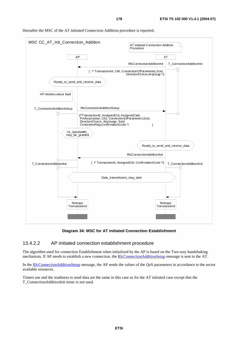
ETSI
ETSI TS 102 000 V1.4.1 (2004-07) 178
Hereafter the MSC of the AT initiated Connection Addition procedure is reported.
AT initiated Connection Addition Procedure
ATAP
ReleaseTransactionId
ReleaseTransactionId
AP decides about Said
UL_bandwidth_may_be_granted
Data_transmission_may_start
Ready_to_send_and_receive_data
Ready_to_send_and_receive_data
MSC CC_AT_Init_Connection_Addition
T_ConnectionAdditionInitRlcConnectionAdditionInit
( /* TransactionId, Clid, ConnectionClParameters,Scid,DirectionChoice,ArqUsag */)
RlcConnectionAdditionSetup
(/*TransactionId, AssignedCid, AssignedCaid,PmAssociation, Clid, ConnectionClParameters,Scid,DirectionChoice, ArqUsage, Said, ContentionFlag,ConfirmationCode */ )
T_ConnectionAdditionAck
T_ConnectionAdditionSetup
RlcConnectionAdditionAck
( /* TransactionId, AssignedCid, ConfirmationCode */) T_ConnectionAdditionAck
Diagram 34: MSC for AT initiated Connection Establishment
13.4.2.2 AP initiated connection establishment procedure
The algorithm used for connection Establishment when initialized by the AP is based on the Two-way handshaking mechanism. If AP needs to establish a new connection, the RlcConnectionAdditionSetup message is sent to the AT.
In the RlcConnectionAdditionSetup message, the AP sends the values of the QoS parameters in accordance to the sector available resources.
Timers use and the readiness to send data are the same in this case as for the AT initiated case except that the T_ConnectionAdditionInit timer is not used.

ETSI
ETSI TS 102 000 V1.4.1 (2004-07) 179
Hereafter the MSC of the AP connection Establishment procedure is reported.
ATAP
AP initiated Connection Addition Procedure
ReleaseTransactionId
ReleaseTransactionId
UL_bandwidth_may_be_granted
Data_transmission_may_start
Ready_to_send_and_receive_data
AP decides about Said
Ready_to_send_and_receive_data
MSC CC_AP_Init_Connection_Addition
T_ConnectionAdditionAck
T_ConnectionAdditionSetup
RlcConnectionAdditionAck
( /* TransactionId, AssignedCid, ConfirmationCode */) T_ConnectionAdditionAck
RlcConnectionAdditionSetup
(/*TransactionId, AssignedCid, AssignedCaid,PmAssociation, Clid, ConnectionClParameters,Scid,DirectionChoice, ArqUsage, Said, ContentionFlag,ConfirmationCode */ )
Diagram 35: MSC for AP initiated Connection Establishment
13.4.3 Change of established connection procedure
The change of established connection procedure is needed when any connection parameters shall be modified.
Both the AP and the AT can initiate a change of established connection procedure. There are several reasons why some QoS parameters shall be changed and sometimes they are not strictly relevant to the connection itself (load levelling or the initialization of a new subscriber, etc.).
The Connection Change procedure is not used to change the CID of a connection.
It shall be allowed to change the DirectionChoice parameter so that an asymmetric bi-directional connection is changed into a symmetric one and vice-versa. It shall not be allowed to use the Connection Change procedure to turn a uni-directional connection from uplink to downlink or vice-versa, neither to turn it into a bi-directional connection.
The modification is achieved via signalling procedure described in diagram 36 when initiated by the AT and diagram 37 when initiated by the AP. The procedure is the same as the connection Establishment. When initiated by the AT is based on the Three-way handshaking whereas when initiated by the AP is based on the Two-way handshaking.
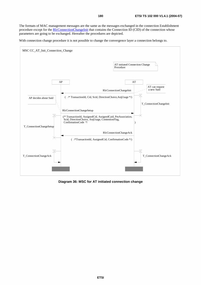
ETSI
ETSI TS 102 000 V1.4.1 (2004-07) 180
The formats of MAC management messages are the same as the messages exchanged in the connection Establishment procedure except for the RlcConnectionChangeInit that contains the Connection ID (CID) of the connection whose parameters are going to be exchanged. Hereafter the procedures are depicted.
With connection change procedure it is not possible to change the convergence layer a connection belongs to.
ATAP
AT initiated Connection Change Procedure
AT can request a new Said
AP decides about Said
MSC CC_AT_Init_Connection_Change
RlcConnectionChangeSetup
(/* TransactionId, AssignedCid, AssignedCaid, PmAssociation,Scid, DirectionChoice, ArqUsage, ContentionFlag,ConfirmationCode */ )
RlcConnectionChangeAck
( /*TransactionId, AssignedCid, ConfirmationCode */)
RlcConnectionChangeInit
( /* TransactionId, Cid, Scid, DirectionChoice,ArqUsage */)
T_ConnectionChangeAck T_ConnectionChangeAck
T_ConnectionChangeSetup
T_ConnectionChangeInit
Diagram 36: MSC for AT initiated connection change

ETSI
ETSI TS 102 000 V1.4.1 (2004-07) 181
AP AT
AP initiated Connection Change Procedure
AP decides about Said
MSC CC_AP_Init_Connection_Change
RlcConnectionChangeSetup
(/* TransactionId, AssignedCid, AssignedCaid, PmAssociation,Scid, DirectionChoice, ArqUsage, ContentionFlag, ConfirmationCode */ )
RlcConnectionChangeAck
( /* TransactionId, AssignedCid, ConfirmationCode */)
T_ConnectionChangeAckT_ConnectionChangeAck
T_ConnectionChangeSetup
Diagram 37: MSC for AP initiated connection change
13.4.4 Connection deletion procedure
Every data connection can be released. When a connection is deleted, all resources associated to it are deleted. The connection ID value shall be available to be associated again to new connections.
Either the AP or the AT can initiate a connection termination procedure at any time only in response to the reception of a deletion primitive from the higher layers. This is the only occasion in which this procedure is initiated. The DLC layer shall always try to recover from failures without sending any warning to the upper layer until either the DLC connection is re-established or an incoming deletion primitive is received.
The algorithm used for connection deletion is always a Two-way handshaking.
Two different timers are needed in these procedures:
• T_ConnectionDeletionInit: this is the timer that controls the re-transmission of the RlcConnectionDeletionInit message. When this timer expires a further RlcConnectionDeletionInit message is sent. This timer shall be implemented both in the AT and AP since both entities can initiate a Connection Deletion procedure.
• T_ConnectionDeletionAck: this timer is needed in order to age out the Transaction ID. The non-initiating side shall be ready to resend the RlcConnectionDeletionAck message if an RlcConnectionDeletionInit message with the same transaction ID is received before the expiration of T_ConnectionDeletionAck. The initiating side shall wait a waiting time corresponding to the expiring time of the T_ConnectionDeletionAck timer before reusing the Transaction ID.
The connection termination procedure is depicted in diagram 38 for AT and in diagram 39 for AP initiated connection termination respectively. The formats of the MAC management messages (RlcConnectionAdditionInit, RlcConnectionAdditionSetup, RlcConnectionAdditionAck, RlcConnectionChangeInit, RlcConnectionChangeSetup, RlcConnectionChangeAck, RlcConnectionDeletionInit and RlcConnectionDeletionAck) are specified in annex B.
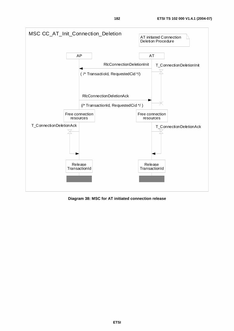
ETSI
ETSI TS 102 000 V1.4.1 (2004-07) 182
AP AT
AT initiated Connection Deletion Procedure
ReleaseTransactionId
ReleaseTransactionId
Free connectionresources
Free connectionresources
MSC CC_AT_Init_Connection_Deletion
RlcConnectionDeletionAck
(/* TransactionId, RequestedCid */ )
RlcConnectionDeletionInit
( /* TransactioId, RequestedCid */)
T_ConnectionDeletionAck T_ConnectionDeletionAck
T_ConnectionDeletionInit
Diagram 38: MSC for AT initiated connection release
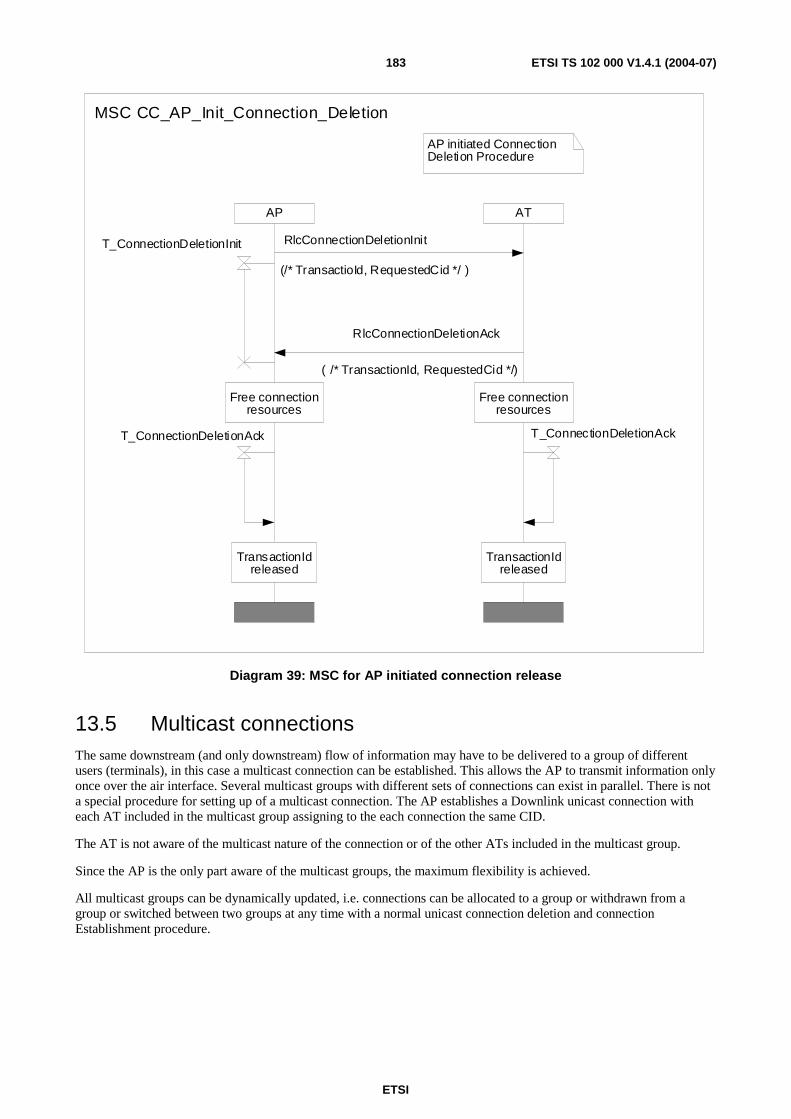
ETSI
ETSI TS 102 000 V1.4.1 (2004-07) 183
ATAP
AP initiated Connection Deletion Procedure
TransactionIdreleased
TransactionIdreleased
Free connectionresources
Free connectionresources
MSC CC_AP_Init_Connection_Deletion
T_ConnectionDeletionInit
T_ConnectionDeletionAck T_ConnectionDeletionAck
RlcConnectionDeletionAck
( /* TransactionId, RequestedCid */)
RlcConnectionDeletionInit
(/* TransactioId, RequestedCid */ )
Diagram 39: MSC for AP initiated connection release
13.5 Multicast connections The same downstream (and only downstream) flow of information may have to be delivered to a group of different users (terminals), in this case a multicast connection can be established. This allows the AP to transmit information only once over the air interface. Several multicast groups with different sets of connections can exist in parallel. There is not a special procedure for setting up of a multicast connection. The AP establishes a Downlink unicast connection with each AT included in the multicast group assigning to the each connection the same CID.
The AT is not aware of the multicast nature of the connection or of the other ATs included in the multicast group.
Since the AP is the only part aware of the multicast groups, the maximum flexibility is achieved.
All multicast groups can be dynamically updated, i.e. connections can be allocated to a group or withdrawn from a group or switched between two groups at any time with a normal unicast connection deletion and connection Establishment procedure.
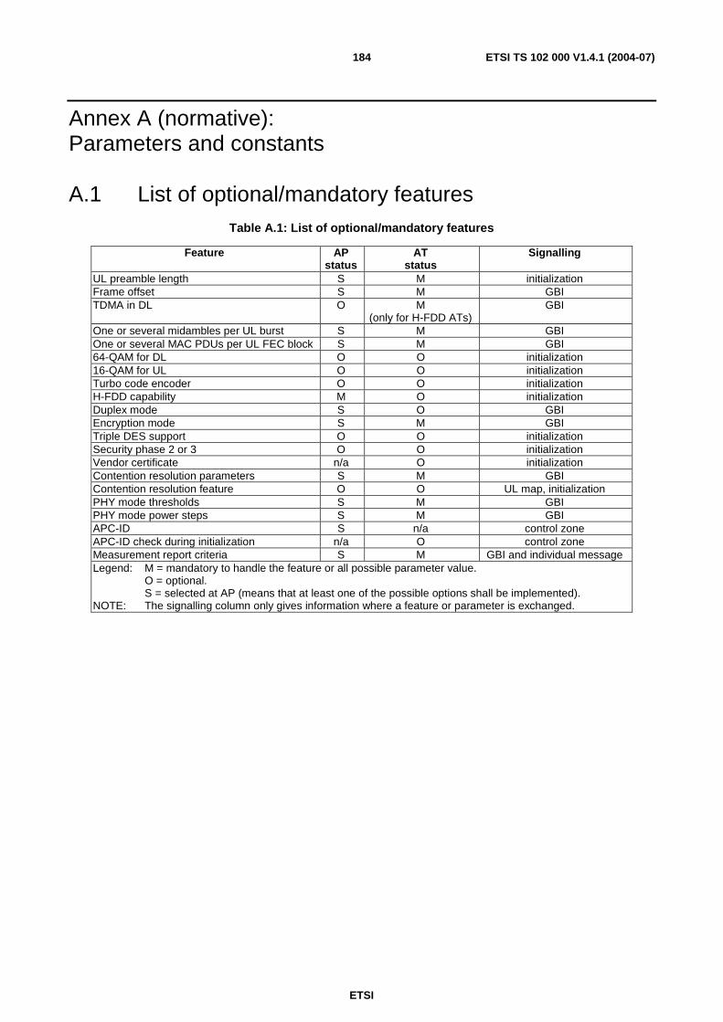
ETSI
ETSI TS 102 000 V1.4.1 (2004-07) 184
Annex A (normative): Parameters and constants
A.1 List of optional/mandatory features Table A.1: List of optional/mandatory features
Feature AP status
AT status
Signalling
UL preamble length S M initialization Frame offset S M GBI TDMA in DL O M
(only for H-FDD ATs) GBI
One or several midambles per UL burst S M GBI One or several MAC PDUs per UL FEC block S M GBI 64-QAM for DL O O initialization 16-QAM for UL O O initialization Turbo code encoder O O initialization H-FDD capability M O initialization Duplex mode S O GBI Encryption mode S M GBI Triple DES support O O initialization Security phase 2 or 3 O O initialization Vendor certificate n/a O initialization Contention resolution parameters S M GBI Contention resolution feature O O UL map, initialization PHY mode thresholds S M GBI PHY mode power steps S M GBI APC-ID S n/a control zone APC-ID check during initialization n/a O control zone Measurement report criteria S M GBI and individual message Legend: M = mandatory to handle the feature or all possible parameter value. O = optional. S = selected at AP (means that at least one of the possible options shall be implemented). NOTE: The signalling column only gives information where a feature or parameter is exchanged.
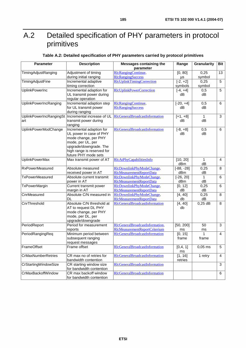
ETSI
ETSI TS 102 000 V1.4.1 (2004-07) 185
A.2 Detailed specification of PHY parameters in protocol primitives
Table A.2: Detailed specification of PHY parameters carried by protocol primitives
Parameter Description Messages containing the parameter
Range Granularity Bit
TimingAdjustRanging Adjustment of timing during initial ranging
RlcRangingContinue, RlcRangingSuccess
[0, 80] µs
0,25 symbol
13
TimingAdjustFine Incremental adaptive timing correction
RlcUplinkTimingCorrection [-2, +2] symbols
0,25 symbol
5
UplinkPowerInc Incremental adaption for UL transmit power during regular operation
RlcUplinkPowerCorrection [-4, +4] dB
0,5 dB
5
UplinkPowerIncRanging Incremental adaption step for UL transmit power during ranging
RlcRangingContinue, RlcRangingSuccess
[-20, +4] dB
0,5 dB
6
UplinkPowerIncRangingStart
Incremental increase of UL transmit power during ranging
RlcGeneralBroadcastInformation [+1, +8] dB
1 dB
3
UplinkPowerModChange Incremental adaption for UL power in case of PHY mode change, per PHY mode, per UL, per upgrade/downgrade. The high range is reserved for future PHY mode sets
RlcGeneralBroadcastInformation [-8, +8] dB
0,5 dB
6
UplinkPowerMax Max transmit power of AT RlcAtPhyCapabilitiesInfo [10, 20] dBm
1 dB
4
RxPowerMeasured Absolute measured received power in AT
RlcDownlinkPhyModeChange, RlcMeasurementReportData
[-88, -28] dBm
0,25 dB
8
TxPowerMeasured Absolute current transmit power in AT
RlcDownlinkPhyModeChange, RlcMeasurementReportData
[-26, 20] dBm
1 dB
6
TxPowerMargin Current transmit power margin in AT
RlcDownlinkPhyModeChange, RlcMeasurementReportData
[0, 12] dB
0,25 dB
6
CnrMeasured Absolute C/N measured in DL
RlcDownlinkPhyModeChange, RlcMeasurementReportData
[4, 40] db
0,25 dB
8
CnrThreshold Absolute C/N threshold at AT to request DL PHY mode change, per PHY mode, per DL, per upgrade/downgrade
RlcGeneralBroadcastInformation [4, 40] db
0,25 dB 8
PeriodReport Period for measurement reports
RlcGeneralBroadcastInformation, RlcMeasurementReportCriterium
[50, 200] ms
50 ms
3
PeriodRangingReq Minimum period between subsequent ranging request messages
RlcGeneralBroadcastInformation [0, 15] frame
1 frame
4
FrameOffset Frame offset RlcGeneralBroadcastInformation [0,4, 1] ms
0,05 ms 5
CrMaxNumberRetries CR max no of retries for bandwidth contention
RlcGeneralBroadcastInformation [1, 16] retries
1 retry 4
CrStartingWindowSize CR starting window size for bandwidth contention
RlcGeneralBroadcastInformation 3
CrMaxBackoffWindow CR max backoff window for bandwidth contention
RlcGeneralBroadcastInformation 6
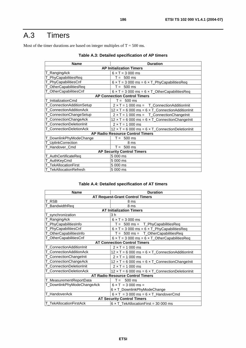
ETSI
ETSI TS 102 000 V1.4.1 (2004-07) 186
A.3 Timers Most of the timer durations are based on integer multiples of T = 500 ms.
Table A.3: Detailed specification of AP timers
Name Duration AP Initialization Timers
T_RangingAck 6 × T = 3 000 ms T_PhyCapabilitiesReq T = 500 ms T_PhyCapabilitiesCnf 6 × T = 3 000 ms = 6 × T_PhyCapabilitiesReq T_OtherCapabilitiesReq T = 500 ms T_OtherCapabilitiesCnf 6 × T = 3 000 ms = 6 × T_OtherCapabilitiesReq
AP Connection Control Timers T_InitializationCmd T = 500 ms T_ConnectionAdditionSetup 2 × T = 1 000 ms = T_ConnectionAdditionInit T_ConnectionAdditionAck 12 × T = 6 000 ms = 6 × T_ConnectionAdditionInit T_ConnectionChangeSetup 2 × T = 1 000 ms = T_ConnectionChangeInit T_ConnectionChangeAck 12 × T = 6 000 ms = 6 × T_ConnectionChangeInit T_ConnectionDeletionInit 2 × T = 1 000 ms T_ConnectionDeletionAck 12 × T = 6 000 ms = 6 × T_ConnectionDeletionInit
AP Radio Resource Control Timers T_DownlinkPhyModeChange T = 500 ms T_UplinkCorrection 8 ms T_Handover_Cmd T = 500 ms
AP Security Control Timers T_AuthCertificateReq 5 000 ms T_AuthKeyCmd 5 000 ms T_TekAllocationFirst 5 000 ms T_TekAllocationRefresh 5 000 ms
Table A.4: Detailed specification of AT timers
Name Duration AT Request-Grant Control Timers
T_RSB 8 ms T_BandwidthReq 8 ms
AT Initialization Timers T_synchronization 3 h T_RangingAck 6 × T = 3 000 ms T_PhyCapabilitiesInfo T = 500 ms = T_PhyCapabilitiesReq T_PhyCapabilitiesCnf 6 × T = 3 000 ms = 6 × T_PhyCapabilitiesReq T_OtherCapabilitiesInfo T = 500 ms = T_OtherCapabilitiesReq T_OtherCapabilitiesCnf 6 × T = 3 000 ms = 6 × T_OtherCapabilitiesReq
AT Connection Control Timers T_ConnectionAdditionInit 2 × T = 1 000 ms T_ConnectionAdditionAck 12 × T = 6 000 ms = 6 × T_ConnectionAdditionInit T_ConnectionChangeInit 2 × T = 1 000 ms T_ConnectionChangeAck 12 × T = 6 000 ms = 6 × T_ConnectionChangeInit T_ConnectionDeletionInit 2 × T = 1 000 ms T_ConnectionDeletionAck 12 × T = 6 000 ms = 6 × T_ConnectionDeletionInit
AT Radio Resource Control Timers T_MeasurementReportData T = 500 ms T_DownlinkPhyModeChangeAck 6 × T = 3 000 ms =
6 × T_DownlinkPhyModeChange T_HandoverAck 6 × T = 3 000 ms = 6 × T_HandoverCmd
AT Security Control Timers T_TekAllocationFirstAck 6 × T_TekAllocationFirst = 30 000 ms
ETSI
ETSI TS 102 000 V1.4.1 (2004-07) 187
For the repetition of messages as described in the MSC diagrams, the following general normative rules shall be applied unless otherwise stated in the text:
• For the AT side, messages shall be repeated after expiration of the associated timer (where this may include very many or up to unlimited repetitions). This applies both for AP-initiated protocols (e.g. PHY capabilities negotiation) as well as AT-initiated protocols (e.g. AT-initiated connection addition). In case of severe errors scenarios, the AP can stop this process and avoid unlimited re-transmissions by commanding a re-initialization of the mis-behaving AT.
• For the AP side, it is recommended to repeat messages after expiration of the associated timer. Such re-transmissions can be repeated for a certain number of times, for instance in case of worse channel conditions. However, the AP can decide to limit the number of re-transmissions to a small number or even to abstain from any re-transmissions and to command instead of this a re-initialization procedure. All these details for the AP side are not specified in order to allow for vendor-AP-specific solutions.
Re-transmission of a message means in most cases that the message is re-sent with the same parameters, in some cases the parameters should be updated to make provisions in case that conditions have changed in the meantime (see the corresponding clauses for more details).
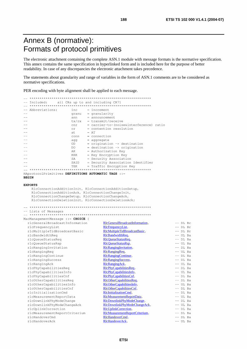
ETSI
ETSI TS 102 000 V1.4.1 (2004-07) 188
Annex B (normative): Formats of protocol primitives The electronic attachment containing the complete ASN.1 module with message formats is the normative specification. This annex contains the same specification in hyperlinked form and is included here for the purpose of better readability. In case of any discrepancies the electronic attachment takes precedence.
The statements about granularity and range of variables in the form of ASN.1 comments are to be considered as normative specifications.
PER encoding with byte alignment shall be applied to each message.
-- ************************************************************* -- Included: all CRs up to and including CR71 -- ************************************************************* -- Abbreviations: inc = increment -- granu = granularity -- ann = announcement -- tx/rx = transmit/receive -- cnr = carrier-to-(noise&interference) ratio -- cr = contention resolution -- at = AT -- conn = connection -- agg = aggregate -- OD = origination -> destination -- DO = destination -> origination -- AK = Authorization Key -- KEK = Key Encryption Key -- SA = Security Association -- SAID = Security Association Identifier -- TEK = Traffic Encryption Key -- ************************************************************* HAprotocolPrimitives DEFINITIONS AUTOMATIC TAGS ::= BEGIN EXPORTS RlcConnectionAdditionInit, RlcConnectionAdditionSetup, RlcConnectionAdditionAck, RlcConnectionChangeInit, RlcConnectionChangeSetup, RlcConnectionChangeAck, RlcConnectionDeletionInit, RlcConnectionDeletionAck; -- ************************************************************* -- Lists of Messages -- ************************************************************* MacManagementMessage ::= CHOICE { rlcGeneralBroadcastInformation RlcGeneralBroadcastInformation, -- DL Br rlcFrequencyList RlcFrequencyList, -- DL Br rlcMultipleTidBroadcastBasic RlcMultipleTidBroadcastBasic, -- DL Br rlcBandwidthReq RlcBandwidthReq, -- UL Ba rlcQueueStatusReq RlcQueueStatusReq, -- DL Ba rlcQueueStatusRsp RlcQueueStatusRsp, -- UL Ba rlcRangingInvitation RlcRangingInvitation, -- DL Ba rlcRangingReq RlcRangingReq, -- UL Ba rlcRangingContinue RlcRangingContinue, -- DL Ba rlcRangingSuccess RlcRangingSuccess, -- DL Ba rlcRangingAck RlcRangingAck, -- UL Ba rlcPhyCapabilitiesReq RlcPhyCapabilitiesReq, -- DL Ba rlcPhyCapabilitiesInfo RlcPhyCapabilitiesInfo, -- UL Ba rlcPhyCapabilitiesCnf RlcPhyCapabilitiesCnf, -- DL Ba rlcOtherCapabilitiesReq RlcOtherCapabilitiesReq, -- DL Ba rlcOtherCapabilitiesInfo RlcOtherCapabilitiesInfo, -- UL Ba rlcOtherCapabilitiesCnf RlcOtherCapabilitiesCnf, -- DL Ba rlcInitializationCmd RlcInitializationCmd, -- DL Ba rlcMeasurementReportData RlcMeasurementReportData, -- UL Ba rlcDownlinkPhyModeChange RlcDownlinkPhyModeChange, -- DL Ba rlcDownlinkPhyModeChangeAck RlcDownlinkPhyModeChangeAck, -- UL Ba rlcUplinkCorrection RlcUplinkCorrection, -- DL Ba rlcMeasurementReportCriterium RlcMeasurementReportCriterium, -- DL Ba rlcHandoverCmd RlcHandoverCmd, -- DL Ba rlcHandoverAck RlcHandoverAck, -- UL Ba

ETSI
ETSI TS 102 000 V1.4.1 (2004-07) 189
rlcAuthCertificateReq RlcAuthCertificateReq, -- DL Pr rlcAuthCertificateInfo RlcAuthCertificateInfo, -- UL Pr rlcAuthReject RlcAuthReject, -- DL Pr rlcAuthKeyCmd RlcAuthKeyCmd, -- DL Pr rlcAuthKeyAck RlcAuthKeyAck, -- UL Pr rlcAuthKeyNack RlcAuthKeyNack, -- UL Pr rlcTekAllocationRefresh RlcTekAllocationRefresh, -- DL Pr rlcTekAllocationFirst RlcTekAllocationFirst, -- DL Pr rlcTekAllocationRefreshAck RlcTekAllocationRefreshAck, -- UL Pr rlcTekAllocationFirstAck RlcTekAllocationFirstAck, -- UL Pr rlcTekAllocationRefreshNack RlcTekAllocationRefreshNack, -- UL Pr rlcTekAllocationFirstNack RlcTekAllocationFirstNack, -- UL Pr rlcTekAllocationFirstTimerStop RlcTekAllocationFirstTimerStop, -- DL Pr rlcConnectionAdditionInit RlcConnectionAdditionInit, -- UL Ba rlcConnectionAdditionSetup RlcConnectionAdditionSetup, -- DL Ba rlcConnectionAdditionAck RlcConnectionAdditionAck, -- UL Ba rlcConnectionChangeInit RlcConnectionChangeInit, -- UL Ba rlcConnectionChangeSetup RlcConnectionChangeSetup, -- DL Ba rlcConnectionChangeAck RlcConnectionChangeAck, -- UL Ba rlcConnectionDeletionInit RlcConnectionDeletionInit, -- Req->NonReq Ba rlcConnectionDeletionAck RlcConnectionDeletionAck, -- NonReq->Req Ba packedMessageDownlinkBasic PackedMessageDownlinkBasic, -- DL Ba packedMessageUplinkBasic PackedMessageUplinkBasic -- UL Ba--} MessagesForPackingDownlinkBasic ::= CHOICE { rlcQueueStatusReq RlcQueueStatusReq, -- DL Ba rlcRangingContinue RlcRangingContinue, -- DL Ba rlcRangingSuccess RlcRangingSuccess, -- DL Ba rlcPhyCapabilitiesReq RlcPhyCapabilitiesReq, -- DL Ba rlcPhyCapabilitiesCnf RlcPhyCapabilitiesCnf, -- DL Ba rlcOtherCapabilitiesReq RlcOtherCapabilitiesReq, -- DL Ba rlcOtherCapabilitiesCnf RlcOtherCapabilitiesCnf, -- DL Ba rlcInitializationCmd RlcInitializationCmd, -- DL Ba rlcDownlinkPhyModeChange RlcDownlinkPhyModeChange, -- DL Ba rlcUplinkCorrection RlcUplinkCorrection, -- DL Ba rlcMeasurementReportCriterium RlcMeasurementReportCriterium, -- DL Ba rlcConnectionAdditionSetup RlcConnectionAdditionSetup, -- DL Ba rlcConnectionChangeSetup RlcConnectionChangeSetup, -- DL Ba rlcConnectionDeletionInit RlcConnectionDeletionInit, -- Req->NonReq Ba rlcConnectionDeletionAck RlcConnectionDeletionAck -- NonReq->Req Ba--} MessagesForPackingUplinkBasic ::= CHOICE { rlcMeasurementReportData RlcMeasurementReportData, -- UL Ba rlcDownlinkPhyModeChangeAck RlcDownlinkPhyModeChangeAck, -- UL Ba rlcConnectionAdditionInit RlcConnectionAdditionInit, -- UL Ba rlcConnectionAdditionAck RlcConnectionAdditionAck, -- UL Ba rlcConnectionChangeInit RlcConnectionChangeInit, -- UL Ba rlcConnectionChangeAck RlcConnectionChangeAck, -- UL Ba rlcConnectionDeletionInit RlcConnectionDeletionInit, -- Req->NonReq Ba rlcConnectionDeletionAck RlcConnectionDeletionAck -- NonReq->Req Ba-- -- excluded for PackingUplink: ranging bursts, short PDUs, -- initialization (due to PTC), handoverAck--} PackedMessageDownlinkBasic ::= SEQUENCE (SIZE (1..50)) OF MessagesForPackingDownlinkBasic PackedMessageUplinkBasic ::= SEQUENCE (SIZE (1..50)) OF MessagesForPackingUplinkBasic -- ************************************************************* -- Messages for Broadcast and MAC (clause 1 to 8) -- ************************************************************* RlcGeneralBroadcastInformation ::= SEQUENCE { -- broadcast duplexMode DuplexMode, -- 1 bit frameOffset FrameOffset, -- 5 bit tdmaZoneDownlink TdmaZoneDownlink, -- 1 bit encryptionMode EncryptionMode, -- 1 bit uplinkPowerIncRangingStart UplinkPowerIncRangingStart, -- 3 bit, common uplinkPowerMaxRangingStart UplinkPowerMax, -- 4 bit, common downlinkPowerControl DownlinkPowerControl, -- 1 bit periodMeasurementReportGBI PeriodMeasurementReportGBI, -- 3 bit, RRC periodRangingInvitation PeriodRangingInvitation, -- 8 bit, uplinkNumberPduPerFecBlock UplinkNumberPduPerFecBlock, -- 1 bit
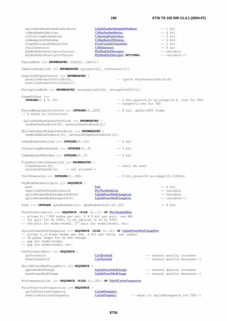
ETSI
ETSI TS 102 000 V1.4.1 (2004-07) 190
uplinkNumberMidamblePerBurst UplinkNumberMidamblePerBurst, -- 1 bit crMaxNumberRetries CrMaxNumberRetries, -- 4 bit crStartingWindowSize CrStartingWindowSize, -- 3 bit crMaxBackoffWindow CrMaxBackoffWindow, -- 3 bit fixedVariableChannelInd FixedVariableChannelInd, -- 1 bit cellDimension CellDimension, -- 9 bit phyModeSetDescriptorCurrent PhyModeSetDescriptor, -- variable phyModeSetDescriptorFuture PhyModeSetDescriptor OPTIONAL -- variable--} DuplexMode ::= ENUMERATED {fdd(0), tdd(1)} TdmaZoneDownlink ::= ENUMERATED {present(0), notPresent(1)} DownlinkPowerControl ::= ENUMERATED { downlinkPowerControlNo(0), -- ignore PhyThresholdsList(0) downlinkPowerControlYes(1)} EncryptionMode ::= ENUMERATED {encryptionOn(0), encryptionOff(1)} FrameOffset ::= INTEGER(0 | 8..20) -- 5 bit,granu=0,05 ms,range=[0,4, 1]ms for FDD -- range={0,1}ms for TDD PeriodRangingInvitation ::= INTEGER(0..255) -- 8 bit, granu=1000 frame -- 0 means no invitations UplinkNumberPduPerFecBlock ::= ENUMERATED { onePduPerFecBlock(0), severalPerFecBlock(1)} UplinkNumberMidamblePerBurst ::= ENUMERATED { oneMidamblePerBurst(0), severalMidamblePerBurst(1)} CrMaxNumberRetries ::= INTEGER(0..15) -- 4 bit CrStartingWindowSize ::= INTEGER(0..4) -- 3 bit CrMaxBackoffWindow ::= INTEGER(0..7) -- 3 bit FixedVariableChannelInd ::= ENUMERATED { fixedChannel(0), -- shall be used variableChannel(1) -- not allowed--} CellDimension ::= INTEGER(0..300) -- 9 bit,granu=50 ms,range=[0,15000]m PhyModeSetDescriptor ::= SEQUENCE { psdi Psdi, -- 4 bit downlinkPhyThresholdsList PhyThresholdsList, -- variable uplinkPowerModChangeListNonTc UplinkPowerModChangeList, -- variable uplinkPowerModChangeListTc UplinkPowerModChangeList -- variable--} Psdi ::= INTEGER {phyModeSet1(1), phyModeSet2(2)}(0..15) -- 4 bit PhyThresholdsList ::= SEQUENCE (SIZE (2..7)) OF PhyThresholdPair -- allows 2..7 PHY modes per set, 2 × 8 bit per pair, see RRC -- 1st pair for DL ATPC, to be ignored if no DL ATPC -- 2nd pair for mode1/mode2, 3rd pair for mode2/mode3, etc. UplinkPowerModChangeList ::= SEQUENCE (SIZE (1..6)) OF UplinkPowerModChangePair -- allows 1..6 Power modes per set, 6 bit per entry, see common -- TX power steps for UL PHY change -- gap for mode1/mode2, -- gap for mode2/mode3, etc. PhyThresholdPair ::= SEQUENCE { upThreshold CnrThreshold, -- channel quality increase downThreshold CnrThreshold -- channel quality decrease--} UplinkPowerModChangePair ::= SEQUENCE { upPowerModChange UplinkPowerModChange, -- channel quality increase downPowerModChange UplinkPowerModChange -- channel quality decrease--} RlcFrequencyList ::= SEQUENCE (SIZE (1..32)) OF PairOfCarrierFrequencies PairOfCarrierFrequencies ::= SEQUENCE { uplinkCarrierFrequency CarrierFrequency, downlinkCarrierFrequency CarrierFrequency -- equal to uplinkFrequency for TDD--}
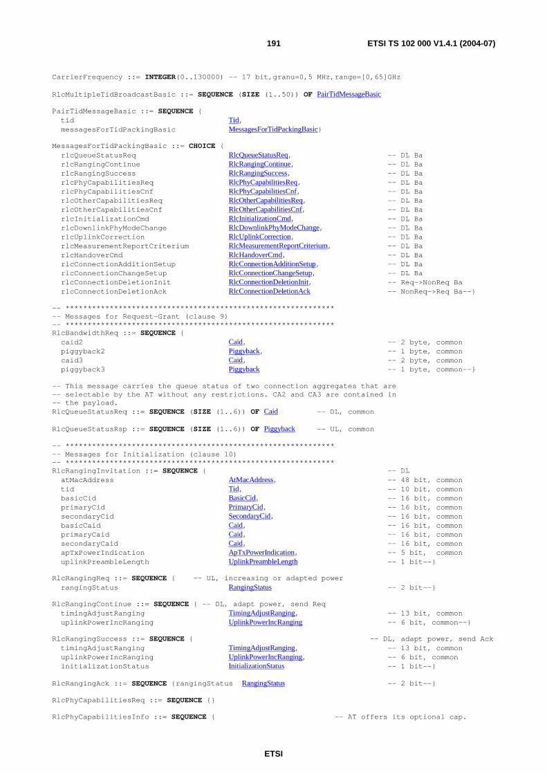
ETSI
ETSI TS 102 000 V1.4.1 (2004-07) 191
CarrierFrequency ::= INTEGER(0..130000) -- 17 bit,granu=0,5 MHz,range=[0,65]GHz RlcMultipleTidBroadcastBasic ::= SEQUENCE (SIZE (1..50)) OF PairTidMessageBasic PairTidMessageBasic ::= SEQUENCE { tid Tid, messagesForTidPackingBasic MessagesForTidPackingBasic} MessagesForTidPackingBasic ::= CHOICE { rlcQueueStatusReq RlcQueueStatusReq, -- DL Ba rlcRangingContinue RlcRangingContinue, -- DL Ba rlcRangingSuccess RlcRangingSuccess, -- DL Ba rlcPhyCapabilitiesReq RlcPhyCapabilitiesReq, -- DL Ba rlcPhyCapabilitiesCnf RlcPhyCapabilitiesCnf, -- DL Ba rlcOtherCapabilitiesReq RlcOtherCapabilitiesReq, -- DL Ba rlcOtherCapabilitiesCnf RlcOtherCapabilitiesCnf, -- DL Ba rlcInitializationCmd RlcInitializationCmd, -- DL Ba rlcDownlinkPhyModeChange RlcDownlinkPhyModeChange, -- DL Ba rlcUplinkCorrection RlcUplinkCorrection, -- DL Ba rlcMeasurementReportCriterium RlcMeasurementReportCriterium, -- DL Ba rlcHandoverCmd RlcHandoverCmd, -- DL Ba rlcConnectionAdditionSetup RlcConnectionAdditionSetup, -- DL Ba rlcConnectionChangeSetup RlcConnectionChangeSetup, -- DL Ba rlcConnectionDeletionInit RlcConnectionDeletionInit, -- Req->NonReq Ba rlcConnectionDeletionAck RlcConnectionDeletionAck -- NonReq->Req Ba--} -- ************************************************************* -- Messages for Request-Grant (clause 9) -- ************************************************************* RlcBandwidthReq ::= SEQUENCE { caid2 Caid, -- 2 byte, common piggyback2 Piggyback, -- 1 byte, common caid3 Caid, -- 2 byte, common piggyback3 Piggyback -- 1 byte, common--} -- This message carries the queue status of two connection aggregates that are -- selectable by the AT without any restrictions. CA2 and CA3 are contained in -- the payload. RlcQueueStatusReq ::= SEQUENCE (SIZE (1..6)) OF Caid -- DL, common RlcQueueStatusRsp ::= SEQUENCE (SIZE (1..6)) OF Piggyback -- UL, common -- ************************************************************* -- Messages for Initialization (clause 10) -- ************************************************************* RlcRangingInvitation ::= SEQUENCE { -- DL atMacAddress AtMacAddress, -- 48 bit, common tid Tid, -- 10 bit, common basicCid BasicCid, -- 16 bit, common primaryCid PrimaryCid, -- 16 bit, common secondaryCid SecondaryCid, -- 16 bit, common basicCaid Caid, -- 16 bit, common primaryCaid Caid, -- 16 bit, common secondaryCaid Caid, -- 16 bit, common apTxPowerIndication ApTxPowerIndication, -- 5 bit, common uplinkPreambleLength UplinkPreambleLength -- 1 bit--} RlcRangingReq ::= SEQUENCE { -- UL, increasing or adapted power rangingStatus RangingStatus -- 2 bit--} RlcRangingContinue ::= SEQUENCE { -- DL, adapt power, send Req timingAdjustRanging TimingAdjustRanging, -- 13 bit, common uplinkPowerIncRanging UplinkPowerIncRanging -- 6 bit, common--} RlcRangingSuccess ::= SEQUENCE { -- DL, adapt power, send Ack timingAdjustRanging TimingAdjustRanging, -- 13 bit, common uplinkPowerIncRanging UplinkPowerIncRanging, -- 6 bit, common initializationStatus InitializationStatus -- 1 bit--} RlcRangingAck ::= SEQUENCE {rangingStatus RangingStatus -- 2 bit--} RlcPhyCapabilitiesReq ::= SEQUENCE {} RlcPhyCapabilitiesInfo ::= SEQUENCE { -- AT offers its optional cap.
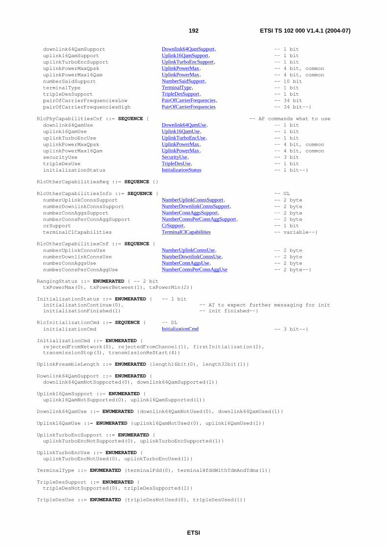
ETSI
ETSI TS 102 000 V1.4.1 (2004-07) 192
downlink64QamSupport Downlink64QamSupport, -- 1 bit uplink16QamSupport Uplink16QamSupport, -- 1 bit uplinkTurboEncSupport UplinkTurboEncSupport, -- 1 bit uplinkPowerMaxQpsk UplinkPowerMax, -- 4 bit, common uplinkPowerMax16Qam UplinkPowerMax, -- 4 bit, common numberSaidSupport NumberSaidSupport, -- 10 bit terminalType TerminalType, -- 1 bit tripleDesSupport TripleDesSupport, -- 1 bit pairOfCarrierFrequenciesLow PairOfCarrierFrequencies, -- 34 bit pairOfCarrierFrequenciesHigh PairOfCarrierFrequencies -- 34 bit--} RlcPhyCapabilitiesCnf ::= SEQUENCE { -- AP commands what to use downlink64QamUse Downlink64QamUse, -- 1 bit uplink16QamUse Uplink16QamUse, -- 1 bit uplinkTurboEncUse UplinkTurboEncUse, -- 1 bit uplinkPowerMaxQpsk UplinkPowerMax, -- 4 bit, common uplinkPowerMax16Qam UplinkPowerMax, -- 4 bit, common securityUse SecurityUse, -- 3 bit tripleDesUse TripleDesUse, -- 1 bit initializationStatus InitializationStatus -- 1 bit--} RlcOtherCapabilitiesReq ::= SEQUENCE {} RlcOtherCapabilitiesInfo ::= SEQUENCE { -- UL numberUplinkConnsSupport NumberUplinkConnsSupport, -- 2 byte numberDownlinkConnsSupport NumberDownlinkConnsSupport, -- 2 byte numberConnAggsSupport NumberConnAggsSupport, -- 2 byte numberConnsPerConnAggSupport NumberConnsPerConnAggSupport, -- 2 byte crSupport CrSupport, -- 1 bit terminalClCapabilities TerminalClCapabilities -- variable--} RlcOtherCapabilitiesCnf ::= SEQUENCE { numberUplinkConnsUse NumberUplinkConnsUse, -- 2 byte numberDownlinkConnsUse NumberDownlinkConnsUse, -- 2 byte numberConnAggsUse NumberConnAggsUse, -- 2 byte numberConnsPerConnAggUse NumberConnsPerConnAggUse -- 2 byte--} RangingStatus ::= ENUMERATED { -- 2 bit txPowerMax(0), txPowerBetween(1), txPowerMin(2)} InitializationStatus ::= ENUMERATED { -- 1 bit initializationContinue(0), -- AT to expect further messaging for init initializationFinished(1) -- init finished--} RlcInitializationCmd ::= SEQUENCE { -- DL initializationCmd InitializationCmd -- 3 bit--} InitializationCmd ::= ENUMERATED { rejectedFromNetwork(0), rejectedFromChannel(1), firstInitialization(2), transmissionStop(3), transmissionReStart(4)} UplinkPreambleLength ::= ENUMERATED {length16bit(0), length32bit(1)} Downlink64QamSupport ::= ENUMERATED { downlink64QamNotSupported(0), downlink64QamSupported(1)} Uplink16QamSupport ::= ENUMERATED { uplink16QamNotSupported(0), uplink16QamSupported(1)} Downlink64QamUse ::= ENUMERATED {downlink64QamNotUsed(0), downlink64QamUsed(1)} Uplink16QamUse ::= ENUMERATED {uplink16QamNotUsed(0), uplink16QamUsed(1)} UplinkTurboEncSupport ::= ENUMERATED { uplinkTurboEncNotSupported(0), uplinkTurboEncSupported(1)} UplinkTurboEncUse ::= ENUMERATED { uplinkTurboEncNotUsed(0), uplinkTurboEncUsed(1)} TerminalType ::= ENUMERATED {terminalFdd(0), terminalHfddWithTdmAndTdma(1)} TripleDesSupport ::= ENUMERATED { tripleDesNotSupported(0), tripleDesSupported(1)} TripleDesUse ::= ENUMERATED {tripleDesNotUsed(0), tripleDesUsed(1)}
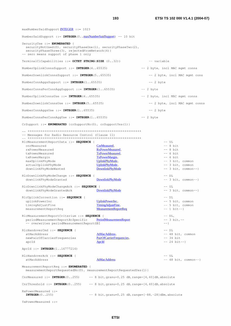
ETSI
ETSI TS 102 000 V1.4.1 (2004-07) 193
maxNumberSaidSupport INTEGER ::= 1023 NumberSaidSupport ::= INTEGER(0..maxNumberSaidSupport) -- 10 bit SecurityUse ::= ENUMERATED { securityNotUsed(0), securityPhaseOne(1), securityPhaseTwo(2), securityPhaseThree(3), rejectedFromNetwork(4)} -- zero means support of phase 1 only TerminalClCapabilities ::= OCTET STRING(SIZE (0..32)) -- variable NumberUplinkConnsSupport ::= INTEGER(4..65535) -- 2 byte, incl MAC mgmt conns NumberDownlinkConnsSupport ::= INTEGER(5..65535) -- 2 byte, incl MAC mgmt cons NumberConnAggsSupport ::= INTEGER(1..65535) -- 2 byte NumberConnsPerConnAggSupport ::= INTEGER(1..65535) -- 2 byte NumberUplinkConnsUse ::= INTEGER(4..65535) -- 2 byte, incl MAC mgmt conns NumberDownlinkConnsUse ::= INTEGER(5..65535) -- 2 byte, incl MAC mgmt conns NumberConnAggsUse ::= INTEGER(1..65535) -- 2 byte NumberConnsPerConnAggUse ::= INTEGER(1..65535) -- 2 byte CrSupport ::= ENUMERATED {crSupportNo(0), crSupportYes(1)} -- ************************************************************* -- Messages for Radio Resource Control (Clause 11) -- ************************************************************* RlcMeasurementReportData ::= SEQUENCE { -- UL cnrMeasured CnrMeasured, -- 8 bit rxPowerMeasured RxPowerMeasured, -- 8 bit txPowerMeasured TxPowerMeasured, -- 6 bit txPowerMargin TxPowerMargin, -- 6 bit maxUplinkPhyMode UplinkPhyMode, -- 3 bit, common actualUplinkPhyMode UplinkPhyMode, -- 3 bit, common downlinkPhyModeWanted DownlinkPhyMode -- 3 bit, common--} RlcDownlinkPhyModeChange ::= SEQUENCE { -- DL downlinkPhyModeGranted DownlinkPhyMode -- 3 bit, common--} RlcDownlinkPhyModeChangeAck ::= SEQUENCE { -- UL downlinkPhyModeGrantedAck DownlinkPhyMode -- 3 bit, common--} RlcUplinkCorrection ::= SEQUENCE { -- DL uplinkPowerInc UplinkPowerInc, -- 5 bit, common timingAdjustFine TimingAdjustFine, -- 5 bit, common measurementReportReq MeasurementReportReq -- 1 bit--} RlcMeasurementReportCriterium ::= SEQUENCE { -- DL, periodMeasurementReportAtSpecific PeriodMeasurementReport -- 3 bit,-- -- overwrites periodMeasurementReportGBI --} RlcHandoverCmd ::= SEQUENCE { -- DL atMacAddress AtMacAddress, -- 48 bit, common newPairOfCarrierFrequencies PairOfCarrierFrequencies, -- 34 bit apcId ApcId -- 24 bit--} ApcId ::= INTEGER(1..16777216) RlcHandoverAck ::= SEQUENCE { -- UL atMacAddress AtMacAddress -- 48 bit, common--} MeasurementReportReq ::= ENUMERATED { measurementReportRequestedNo(0), measurementReportRequestedYes(1)} CnrMeasured ::= INTEGER(0..255) -- 8 bit,granu=0,25 dB,range=[4,40]dB,absolute CnrThreshold ::= INTEGER(0..255) -- 8 bit,granu=0,25 dB,range=[4,40]dB,absolute RxPowerMeasured ::= INTEGER(0..255) -- 8 bit,granu=0,25 dB,range=[-88,-28]dBm,absolute TxPowerMeasured ::=
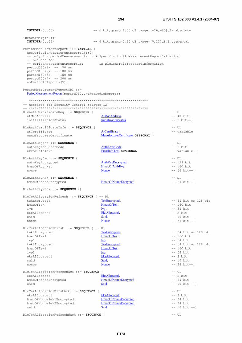
ETSI
ETSI TS 102 000 V1.4.1 (2004-07) 194
INTEGER(0..63) -- 6 bit,granu=1,00 dB,range=[-26,+20]dBm,absolute TxPowerMargin ::= INTEGER(0..63) -- 6 bit,granu=0,25 dB,range=[0,12]dB,incremental PeriodMeasurementReport ::= INTEGER { usePeriodicMeasurementReportGBI(0), -- only for periodMeasurementReportAtSpecific in RlcMeasurementReportCriterium, -- but not for -- periodMeasurementReportGBI in RlcGeneralBroadcastInformation period050(1), -- 50 ms period100(2), -- 100 ms period150(3), -- 150 ms period200(4), -- 200 ms noPeriodicReports(5)} PeriodMeasurementReportGBI ::= PeriodMeasurementReport(period050..noPeriodicReports) -- ************************************************************* -- Messages for Security Control (clause 12) -- ************************************************************* RlcAuthCertificateReq ::= SEQUENCE { -- DL atMacAddress AtMacAddress, -- 48 bit initializationStatus InitializationStatus -- 1 bit--} RlcAuthCertificateInfo ::= SEQUENCE { -- UL atCertificate AtCertificate, -- variable manufacturerCertificate ManufacturerCertificate OPTIONAL } RlcAuthReject ::= SEQUENCE { -- DL authRejectErrorCode AuthErrorCode, -- 1 bit errorInfoText ErrorInfoText OPTIONAL -- variable--} RlcAuthKeyCmd ::= SEQUENCE { -- DL authKeyEncrypted AuthKeyEncrypted, -- 128 bit hmacOfAuthKey HmacOfAuthKey, -- 160 bit nonce Nonce -- 64 bit--} RlcAuthKeyAck ::= SEQUENCE { -- DL hmacOfNonceEncrypted HmacOfNonceEncrypted -- 64 bit--} RlcAuthKeyNack ::= SEQUENCE {} RlcTekAllocationRefresh ::= SEQUENCE { -- DL tekEncrypted TekEncrypted, -- 64 bit or 128 bit hmacOfTek HmacOfTek, -- 160 bit ivp Ivp, -- 64 bit eksAllocated EksAllocated, -- 2 bit said Said, -- 10 bit nonce Nonce -- 64 bit--} RlcTekAllocationFirst ::= SEQUENCE { -- DL tek1Encrypted TekEncrypted, -- 64 bit or 128 bit hmacOfTek1 HmacOfTek, -- 160 bit ivp1 Ivp, -- 64 bit tek2Encrypted TekEncrypted, -- 64 bit or 128 bit hmacOfTek2 HmacOfTek, -- 160 bit ivp2 Ivp, -- 64 bit eksAllocated1 EksAllocated, -- 2 bit said Said, -- 10 bit nonce Nonce -- 64 bit--} RlcTekAllocationRefreshAck ::= SEQUENCE { -- UL eksAllocated EksAllocated, -- 2 bit hmacOfNonceEncrypted HmacOfNonceEncrypted, -- 64 bit said Said -- 10 bit --} RlcTekAllocationFirstAck ::= SEQUENCE { -- UL eksAllocated1 EksAllocated, -- 2 bit hmacOfNonceTek1Encrypted HmacOfNonceEncrypted, -- 64 bit hmacOfNonceTek2Encrypted HmacOfNonceEncrypted, -- 64 bit said Said -- 10 bit --} RlcTekAllocationRefreshNack ::= SEQUENCE { -- UL
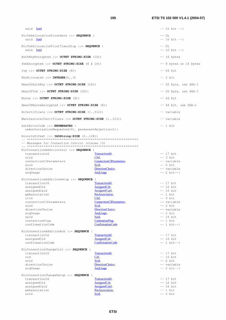
ETSI
ETSI TS 102 000 V1.4.1 (2004-07) 195
said Said -- 10 bit --} RlcTekAllocationFirstNack ::= SEQUENCE { -- UL said Said -- 10 bit --} RlcTekAllocationFirstTimerStop ::= SEQUENCE { -- DL said Said -- 10 bit --} AuthKeyEncrypted ::= OCTET STRING(SIZE (16)) -- 16 bytes TekEncrypted ::= OCTET STRING(SIZE (8 | 16)) -- 8 bytes or 16 bytes Ivp ::= OCTET STRING(SIZE (8)) -- 64 bit EksAllocated ::= INTEGER(0..3) -- 2 bit HmacOfAuthKey ::= OCTET STRING(SIZE (20)) -- 20 byte, use SHA-1 HmacOfTek ::= OCTET STRING(SIZE (20)) -- 20 byte, use SHA-1 Nonce ::= OCTET STRING(SIZE (8)) -- 64 bit HmacOfNonceEncrypted ::= OCTET STRING(SIZE (8)) -- 64 bit, use SHA-1 AtCertificate ::= OCTET STRING(SIZE (1..512)) -- variable ManufacturerCertificate ::= OCTET STRING(SIZE (1..512)) -- variable AuthErrorCode ::= ENUMERATED { -- 1 bit reAuthorizationRequested(0), permanentRejection(1)} ErrorInfoText ::= IA5String(SIZE (0..128)) -- ************************************************************* -- Messages for Connection Control (clause 13) -- ************************************************************* RlcConnectionAdditionInit ::= SEQUENCE { transactionId TransactionId, -- 17 bit clid Clid, -- 3 bit connectionClParameters ConnectionClParameters, -- variable scid Scid, -- 2 bit directionChoice DirectionChoice, -- variable arqUsage ArqUsage -- 2 bit--} RlcConnectionAdditionSetup ::= SEQUENCE { transactionId TransactionId, -- 17 bit assignedCid AssignedCid, -- 16 bit assignedCaid AssignedCaid, -- 16 bit pmAssociation PmAssociation, -- 1 bit clid Clid, -- 3 bit connectionClParameters ConnectionClParameters, -- variable scid Scid, -- 2 bit directionChoice DirectionChoice, -- variable arqUsage ArqUsage, -- 2 bit said Said, -- 16 bit contentionFlag ContentionFlag, -- 1 bit confirmationCode ConfirmationCode -- 1 bit--} RlcConnectionAdditionAck ::= SEQUENCE { transactionId TransactionId, -- 17 bit assignedCid AssignedCid, -- 16 bit confirmationCode ConfirmationCode -- 1 bit--} RlcConnectionChangeInit ::= SEQUENCE { transactionId TransactionId, -- 17 bit cid Cid, -- 16 bit scid Scid, -- 2 bit directionChoice DirectionChoice, -- variable arqUsage ArqUsage -- 2 bit--} RlcConnectionChangeSetup ::= SEQUENCE { transactionId TransactionId, -- 17 bit assignedCid AssignedCid, -- 16 bit assignedCaid AssignedCaid, -- 16 bit pmAssociation PmAssociation, -- 1 bit scid Scid, -- 2 bit
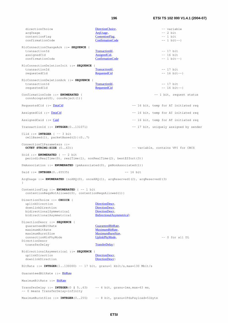
ETSI
ETSI TS 102 000 V1.4.1 (2004-07) 196
directionChoice DirectionChoice, -- variable arqUsage ArqUsage, -- 2 bit contentionFlag ContentionFlag, -- 1 bit confirmationCode ConfirmationCode -- 1 bit--} RlcConnectionChangeAck ::= SEQUENCE { transactionId TransactionId, -- 17 bit assignedCid AssignedCid, -- 16 bit confirmationCode ConfirmationCode -- 1 bit--} RlcConnectionDeletionInit ::= SEQUENCE { transactionId TransactionId, -- 17 bit requestedCid RequestedCid -- 16 bit--} RlcConnectionDeletionAck ::= SEQUENCE { transactionId TransactionId, -- 17 bit requestedCid RequestedCid -- 16 bit--} ConfirmationCode ::= ENUMERATED { -- 1 bit, request status connAccepted(0), connReject(1)} RequestedCid ::= DataCid -- 16 bit, temp for AT initiated req AssignedCid ::= DataCid -- 16 bit, temp for AT initiated req AssignedCaid ::= Caid -- 16 bit, temp for AT initiated req TransactionId ::= INTEGER(0..131071) -- 17 bit, uniquely assigned by sender Clid ::= INTEGER { -- 3 bit cellBased(1), packetBased(2)}(0..7) ConnectionClParameters ::= OCTET STRING(SIZE (0..63)) -- variable, contains VPI for CBCS Scid ::= ENUMERATED { -- 2 bit periodicRealTime(0), realTime(1), nonRealTime(2), bestEffort(3)} PmAssociation ::= ENUMERATED {pmAssociated(0), pmNonAssociated(1)} Said ::= INTEGER(0..65535) -- 16 bit ArqUsage ::= ENUMERATED {noARQ(0), onceARQ(1), arqReserved1(2), arqReserved2(3) } ContentionFlag ::= ENUMERATED { -- 1 bit contentionReqsNotAllowed(0), contentionReqsAllowed(1)} DirectionChoice ::= CHOICE { uplinkDirection DirectionDescr, downlinkDirection DirectionDescr, bidirectionalSymmetrical DirectionDescr, bidirectionalAsymmetrical BidirectionalAsymmetrical} DirectionDescr ::= SEQUENCE { guaranteedBitRate GuaranteedBitRate, maximumBitRate MaximumBitRate, maximumBurstSize MaximumBurstSize, connectionMinPhyMode UplinkPhyMode, -- 0 for all DL DirectionDescr transferDelay TransferDelay} BidirectionalAsymmetrical ::= SEQUENCE { uplinkDirection DirectionDescr, downlinkDirection DirectionDescr} BitRate ::= INTEGER(1..130000) -- 17 bit, granu=1 kbit/s,max=130 Mbit/s GuaranteedBitRate ::= BitRate MaximumBitRate ::= BitRate TransferDelay ::= INTEGER(0 | 5..63) -- 6 bit, granu=1ms,max=63 ms, -- 0 means TransferDelay=infinity MaximumBurstSize ::= INTEGER(0..255) -- 8 bit, granu=1PduPayload=51byte
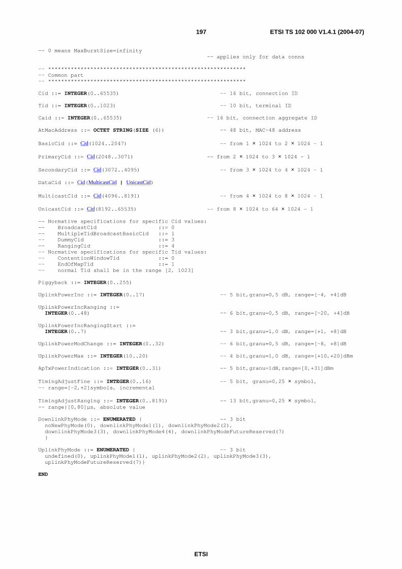
ETSI
ETSI TS 102 000 V1.4.1 (2004-07) 197
-- 0 means MaxBurstSize=infinity -- applies only for data conns -- ************************************************************* -- Common part -- ************************************************************* Cid ::= INTEGER(0..65535) -- 16 bit, connection ID Tid ::= INTEGER(0..1023) -- 10 bit, terminal ID Caid ::= INTEGER(0..65535) -- 16 bit, connection aggregate ID AtMacAddress ::= OCTET STRING(SIZE (6)) -- 48 bit, MAC-48 address BasicCid ::= Cid(1024..2047) -- from 1 × 1024 to 2 × 1024 - 1 PrimaryCid ::= Cid(2048..3071) -- from 2 × 1024 to 3 × 1024 - 1 SecondaryCid ::= Cid(3072..4095) -- from 3 × 1024 to 4 × 1024 - 1 DataCid ::= Cid(MulticastCid | UnicastCid) MulticastCid ::= Cid(4096..8191) -- from 4 × 1024 to 8 × 1024 - 1 UnicastCid ::= Cid(8192..65535) -- from 8 × 1024 to 64 × 1024 - 1 -- Normative specifications for specific Cid values: -- BroadcastCid ::= 0 -- MultipleTidBroadcastBasicCid ::= 1 -- DummyCid ::= 3 -- RangingCid ::= 4 -- Normative specifications for specific Tid values: -- ContentionWindowTid ::= 0 -- EndOfMapTid ::= 1 -- normal Tid shall be in the range [2, 1023] Piggyback ::= INTEGER(0..255) UplinkPowerInc ::= INTEGER(0..17) -- 5 bit,granu=0,5 dB, range=[-4, +4]dB UplinkPowerIncRanging ::= INTEGER(0..48) -- 6 bit,granu=0,5 dB, range=[-20, +4]dB UplinkPowerIncRangingStart ::= INTEGER(0..7) -- 3 bit,granu=1,0 dB, range=[+1, +8]dB UplinkPowerModChange ::= INTEGER(0..32) -- 6 bit,granu=0,5 dB, range=[-8, +8]dB UplinkPowerMax ::= INTEGER(10..20) -- 4 bit,granu=1,0 dB, range=[+10,+20]dBm ApTxPowerIndication ::= INTEGER(0..31) -- 5 bit,granu=1dB,range=[0,+31]dBm TimingAdjustFine ::= INTEGER(0..16) -- 5 bit, granu=0,25 × symbol, -- range=[-2,+2]symbols, incremental TimingAdjustRanging ::= INTEGER(0..8191) -- 13 bit,granu=0,25 × symbol, -- range}[0,80]µs, absolute value DownlinkPhyMode ::= ENUMERATED { -- 3 bit noNewPhyMode(0), downlinkPhyMode1(1), downlinkPhyMode2(2), downlinkPhyMode3(3), downlinkPhyMode4(4), downlinkPhyModeFutureReserved(7) } UplinkPhyMode ::= ENUMERATED { -- 3 bit undefined(0), uplinkPhyMode1(1), uplinkPhyMode2(2), uplinkPhyMode3(3), uplinkPhyModeFutureReserved(7)} END

ETSI
ETSI TS 102 000 V1.4.1 (2004-07) 198
Annex C (informative): Formats of service primitives
Table C.1: Complete ASN.1 description of service primitives
HAservicePrimitives DEFINITIONS AUTOMATIC TAGS ::= BEGIN IMPORTS RlcConnectionAdditionInit, RlcConnectionAdditionSetup, RlcConnectionAdditionAck, RlcConnectionChangeInit, RlcConnectionChangeSetup, RlcConnectionChangeAck, RlcConnectionDeletionInit, RlcConnectionDeletionAck FROM HAprotocolPrimitives; -- ************************************************************* -- Lists of service primitives (for connection control) -- ************************************************************* DlcConnectionAdditionInitReq ::= RlcConnectionAdditionInit DlcConnectionAdditionInitInd ::= RlcConnectionAdditionInit DlcConnectionAdditionReq ::= RlcConnectionAdditionSetup DlcConnectionAdditionInd ::= RlcConnectionAdditionSetup DlcConnectionAdditionRsp ::= RlcConnectionAdditionAck DlcConnectionAdditionCnf ::= RlcConnectionAdditionAck DlcConnectionChangeInitReq ::= RlcConnectionChangeInit DlcConnectionChangeInitInd ::= RlcConnectionChangeInit DlcConnectionChangeReq ::= RlcConnectionChangeSetup DlcConnectionChangeInd ::= RlcConnectionChangeSetup DlcConnectionChangeRsp ::= RlcConnectionChangeAck DlcConnectionChangeCnf ::= RlcConnectionChangeAck DlcConnectionDeletionReq ::= RlcConnectionDeletionInit DlcConnectionDeletionInd ::= RlcConnectionDeletionInit DlcConnectionDeletionRsp ::= RlcConnectionDeletionAck DlcConnectionDeletionCnf ::= RlcConnectionDeletionAck END
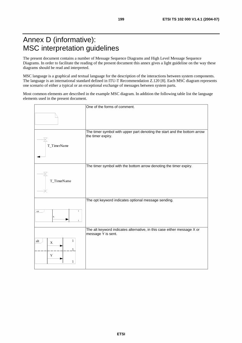
ETSI
ETSI TS 102 000 V1.4.1 (2004-07) 199
Annex D (informative): MSC interpretation guidelines The present document contains a number of Message Sequence Diagrams and High Level Message Sequence Diagrams. In order to facilitate the reading of the present document this annex gives a light guideline on the way these diagrams should be read and interpreted.
MSC language is a graphical and textual language for the description of the interactions between system components. The language is an international standard defined in ITU-T Recommendation Z.120 [8]. Each MSC diagram represents one scenario of either a typical or an exceptional exchange of messages between system parts.
Most common elements are described in the example MSC diagram. In addition the following table list the language elements used in the present document.
One of the forms of comment.
T_TimerName
The timer symbol with upper part denoting the start and the bottom arrow the timer expiry.
T_TimerName
The timer symbol with the bottom arrow denoting the timer expiry.
1
1 opt X
The opt keyword indicates optional message sending.
1
1 alt
1
Y
X
The alt keyword indicates alternative, in this case either message X or message Y is sent.

ETSI
ETSI TS 102 000 V1.4.1 (2004-07) 200
AP AT
MSC ExampleMSC
1
1 exc
EndCondition
local action ContinueCondition
loop <0, n> LoopMscReference
local action
MediumCondition
StartCondition
This is a comments
local action
same TekSeqNo
new TEK, IVAP is chosen
Reply
( /* Said, [TEKn+1] encrypted with AK, IVAP, Hmac, TekLifeTime, TekSeqNo, InitializationStatus */ )
T_Req Req
Reject
Diagram name
Communicating entity
Condition
Message from AT to AP
The box with keyword exc shows actions perforemed if exceptional conditions are met. The actions below are not executed if the exceptional conditions are met and other way around.
Timer start symbol
The activities defined in the MSC reference are executed zero to m times.
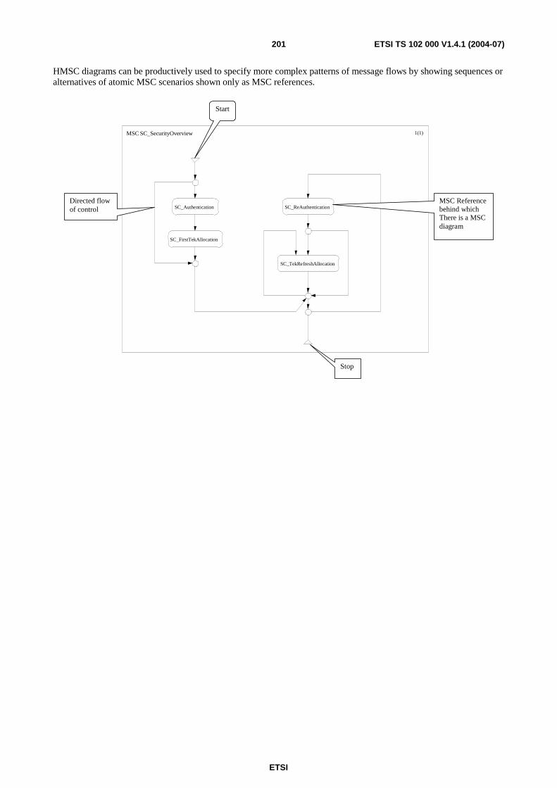
ETSI
ETSI TS 102 000 V1.4.1 (2004-07) 201
HMSC diagrams can be productively used to specify more complex patterns of message flows by showing sequences or alternatives of atomic MSC scenarios shown only as MSC references.
MSC SC_SecurityOverview 1(1)
SC_Authentication
SC_FirstTekAllocation
SC_ReAuthentication
SC_TekRefreshAllocation
Start
Stop
MSC Reference behind which There is a MSC diagram
Directed flow of control
ETSI
ETSI TS 102 000 V1.4.1 (2004-07) 202
Annex E (normative): SDL specification of DLC protocol
E.1 The HIPERACCESS SDL model The HIPERACCESS SDL model is at this stage a collection of individual models matching more important clauses of the present document. There are models for:
• Radio Resource control;
• Initialization control;
• Connection management control;
• Security control.
The SDL models are formal in the sense that they are free of any syntactic and semantic errors. As such they are suitable for simulation and validation and can serve as a reference implementation or an initial basis for implementation.
The models are integrated with DLC protocol message specification in ASN.1.
Each SDL model has been validated and has been improved until there was no behaviour that is undesired, such as deadlocks, livelocks or similar. There are no states where a message could come without a specified transition that handles such a case.
The models are always trying to capture what is going on in reality. In every model, there are simplifications and these are no exception. In introduction to each model the most notable simplifications will be highlighted and explained.
E.2 Radio Resource Control SDL model The Radio Resource Control is developed as a closed system, i.e. there are two communicating processes representing AP and AT side respectively and there are no other external events that affect the behaviour of the model. In order to do that, the use of some SDL constructs needs to be shortly explained:
• The None event: this is an event that can trigger a transition without any obvious or explained reason. Both AP and AT radio resource control entities need to make some decisions based on some measurements and other elements. It would be beyond the scope of the model to describe the precise relations between the external conditions leading to some action and the actions that come. For modelling such behaviour the None event is ideal since it models the decision taken by AP or AT without going into the reasons for such a step. For example, one of the None events simulates that some thresholds have been crossed leading to the appropriate Rlc message being sent to the AP side.
• The decision containing the SDL "ANY" operator. The semantic of this is that any of the branches following the decision is taken without linking the path with any specific condition. This construct is useful to show all possible behaviour alternatives without going into details of why a particular branch was chosen. The advantage of using this is that state exploration tools explore possible traces through such decisions thus exercising the model in all ways possible.
• The expression containing "ANY" operator applied to a specific type. For example the application of ANY operator to a type Boolean will yield either true or false. There are situations in modelling where some message parameters need to be filled but their values do not affect the behaviour in any way (or at least not the behaviour of the part that is modelled). It is exactly for such situations that the operator was used.
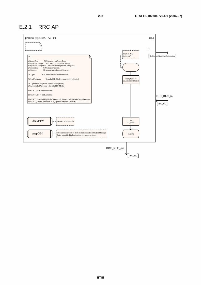
ETSI
ETSI TS 102 000 V1.4.1 (2004-07) 203
E.2.1 RRC AP
process type RRC_AP_PT 1(5)
DCL
mReportData RlcMeasurementReportData, dlPhyModeChange RlcDownlinkPhyModeChange, dlPhyModeChangeAck RlcDownlinkPhyModeChangeAck, ulCorrection RlcUplinkCorrection,mCriterium RlcMeasurementReportCriterium;
DCL gbi RlcGeneralBroadcastInformation;
DCL dlPhyMode DownlinkPhyMode := downlinkPhyMode3;
DCL grantedDlPhyMode DownlinkPhyMode;DCL wantedDlPhyMode DownlinkPhyMode;
TIMER T_GBI := GbiDuration;
TIMER T_end := endDuration;
TIMER T_DownlinkPhyModeChange := T_DownlinkPhyModeChangeDuration;TIMER T_UplinkCorrection := T_UplinkCorrectionDuration;
Start of RRCin the AP
dlPhyMode :=downlinkPhyMode3
set(T_GBI)
Starting
decidePM Decide DL Phy Mode
prepGBI Prepare the content of RlcGeneralBroacastInformationMessageJust a simplified indication that it needsto be done
B
RlcGeneralBroadcastInformation
RRC_RLC_in
(RRC_UL)
RRC_RLC_out
(RRC_DL)

ETSI
ETSI TS 102 000 V1.4.1 (2004-07) 204
process type RRC_AP_PT 2(5)/* The sending of RlcGeneralBroadcastInformationcan be done in any state */
newtype RrcDownlinkPhyModeChangeOperators operators prepPMC: DownlinkPhyMode -> RlcDownlinkPhyModeChange; operator prepPMC; fpar dpm DownlinkPhyMode; returns pmc RlcDownlinkPhyModeChange; start; task pmc!downlinkPhyModeGranted := dpm; return; endoperator;endnewtype;
newtype RrcMeasurementReportCriteriumOperators operators prepCri: Integer /* dummy */ -> RlcMeasurementReportCriterium; operator prepCri; fpar dummy Integer; returns mrCri RlcMeasurementReportCriterium; start; decision any; (/* */): task mrCri!periodMeasurementReportAtSpecific := period050; (/* */): task mrCri!periodMeasurementReportAtSpecific := period100; (/* */): task mrCri!periodMeasurementReportAtSpecific := period150; (/* */): task mrCri!periodMeasurementReportAtSpecific := period200; (/* */): task mrCri!periodMeasurementReportAtSpecific := noPeriodicReports; enddecision; return; endoperator;endnewtype;
newtype RlcUplinkCorrectionOperators operators prepULcorr: Integer /* dummy */ -> RlcUplinkCorrection; operator prepULcorr; fpar dummy Integer; returns ulc RlcUplinkCorrection; start; task ulc!uplinkPowerInc := any(UplinkPowerInc), ulc!timingAdjustFine := any(TimingAdjustFine); decision any; (/* */): task ulc!measurementReportReq := measurementReportRequestedNo; (/* */): task ulc!measurementReportReq := measurementReportRequestedYes; enddecision; return; endoperator;endnewtype;
Starting
T_GBI
RlcGeneralBroad_castInformation( CALL prepGBI)
modelling the GBIsending
set(T_GBI)
Deciding Stay in the same state
*(Starting)
In all states the the RlcGeneralBroadcastInformationmay be sent
T_GBI
RlcGeneralBroad_castInformation( CALL prepGBI)
modelling the GBIsending
set(T_GBI)
- Stay in the same state
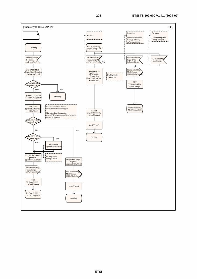
ETSI
ETSI TS 102 000 V1.4.1 (2004-07) 205
process type RRC_AP_PT 3(5)
Deciding
RlcMeasurement_ReportData(mReportData)
wantedDlPhyMode :=mReportData!downlink_
PhyModeWanted
wantedDlPhyMode= noNewPhyMode
grantedDlPhyMode:= wantedDlPhyMode
decidePM(grantedDlPhyMode,
dlPhyMode)
AP decides to allocate AT to another PHY mode region
The procedure changes thegrantedDlPhyMode to noNewPhyModein case of rejection
grantedDlPhyMode= noNewPhyMode
grantedDlPhyMode> dlPhyMode
dlPhyMode:= grantedDlPhyMode
DL Phy Modechanged down
dlPhyModeChange :=prepPMC
(grantedDlPhyMode)
RlcDownlinkPhy_ModeChange(dlPhyModeChange)
SET(T_DownlinkPhy_
ModeChange)
RlcDownlinkPhy_ModeChangeSent
dlPhyModeChange :=prepPMC
(grantedDlPhyMode)
RlcDownlinkPhy_ModeChange(dlPhyModeChange)
reset(T_end)
Deciding
Deciding
RlcDownlinkPhy_ModeChangeSent
RlcDownlinkPhy_ModeChangeAck(dlPhyModeChangeAck)
Normal
dlPhyMode :=dlPhyMode_ChangeAck
!downlinkPhyMode_GrantedAck
DL Phy Modechanged up
RESET(T_DownlinkPhy_
ModeChange)
reset(T_end)
Deciding
RlcMeasurement_ReportData(mReportData)
Exception
DownlinkPhyMode_Change delayed, AP retransmitted
RlcDownlinkPhy_ModeChange(dlPhyModeChange)
SET(T_DownlinkPhy_
ModeChange)
RlcDownlinkPhy_ModeChangeSent
T_DownlinkPhy_ModeChange
Exception
DownlinkPhyMode_Change delayed
false
false
false
true
true
true
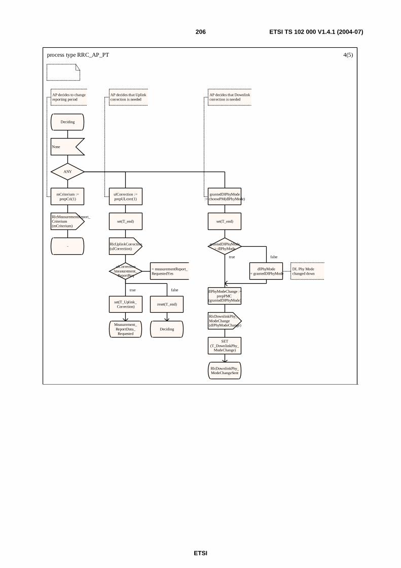
ETSI
ETSI TS 102 000 V1.4.1 (2004-07) 206
process type RRC_AP_PT 4(5)
Deciding
None
ANY
mCriterium :=prepCri(1)
AP decides to changereporting period
RlcMeasurementReport_Criterium(mCriterium)
-
ulCorrection :=prepULcorr(1)
AP decides that Uplinkcorrection is needed
set(T_end)
RlcUplinkCorrection(ulCorrection)
ulCorrection!measurement_
ReportReq
= measurementReport_RequestedYes
set(T_Uplink_Correction)
Measurement_ReportData_Requested
reset(T_end)
Deciding
grantedDlPhyMode:= choosePM(dlPhyMode)
AP decides that Downlinkcorrection is needed
set(T_end)
grantedDlPhyMode> dlPhyMode
dlPhyMode:= grantedDlPhyMode
DL Phy Modechanged down
dlPhyModeChange :=prepPMC
(grantedDlPhyMode)
RlcDownlinkPhy_ModeChange(dlPhyModeChange)
SET(T_DownlinkPhy_
ModeChange)
RlcDownlinkPhy_ModeChangeSent
true false
falsetrue
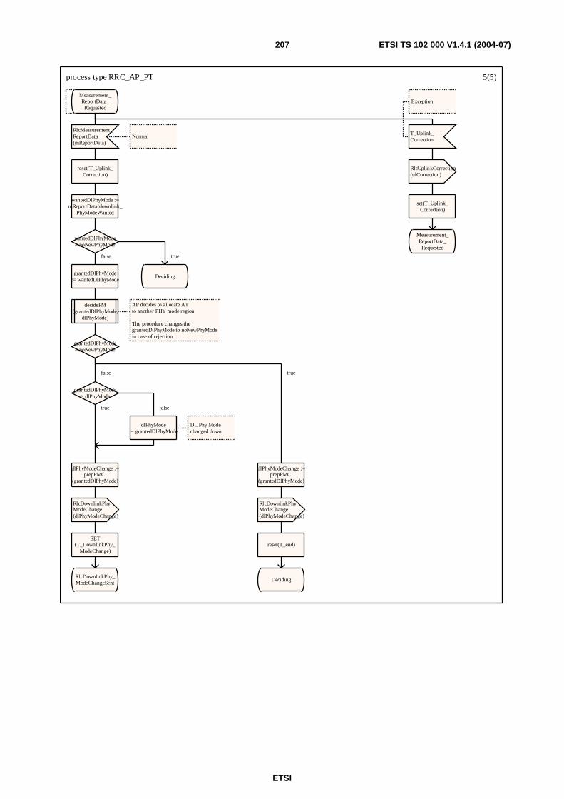
ETSI
ETSI TS 102 000 V1.4.1 (2004-07) 207
process type RRC_AP_PT 5(5)
Measurement_ReportData_Requested
RlcMeasurement_ReportData(mReportData)
Normal
reset(T_Uplink_Correction)
wantedDlPhyMode :=mReportData!downlink_
PhyModeWanted
wantedDlPhyMode= noNewPhyMode
grantedDlPhyMode:= wantedDlPhyMode
decidePM(grantedDlPhyMode,
dlPhyMode)
AP decides to allocate AT to another PHY mode region
The procedure changes thegrantedDlPhyMode to noNewPhyModein case of rejection
grantedDlPhyMode= noNewPhyMode
grantedDlPhyMode> dlPhyMode
dlPhyMode:= grantedDlPhyMode
DL Phy Modechanged down
dlPhyModeChange :=prepPMC
(grantedDlPhyMode)
RlcDownlinkPhy_ModeChange(dlPhyModeChange)
SET(T_DownlinkPhy_
ModeChange)
RlcDownlinkPhy_ModeChangeSent
dlPhyModeChange :=prepPMC
(grantedDlPhyMode)
RlcDownlinkPhy_ModeChange(dlPhyModeChange)
reset(T_end)
Deciding
Deciding
T_Uplink_Correction
Exception
RlcUplinkCorrection(ulCorrection)
set(T_Uplink_Correction)
Measurement_ReportData_Requested
false
false
falsetrue
true
true

ETSI
ETSI TS 102 000 V1.4.1 (2004-07) 208
E.2.2 RRC AT
process type RRC_AT_PT 1(4)
TIMER T_MeasurementReportData := T_MeasurementReportDataDuration;
DCL
mReportData RlcMeasurementReportData, dlPhyModeChange RlcDownlinkPhyModeChange, dlPhyModeChangeAck RlcDownlinkPhyModeChangeAck, ulCorrection RlcUplinkCorrection,mCriterium RlcMeasurementReportCriterium;
DCL gbi RlcGeneralBroadcastInformation;
DCL dlPhyMode DownlinkPhyMode := downlinkPhyMode3;
DCL grantedDlPhyMode DownlinkPhyMode;DCL wantedDlPhyMode DownlinkPhyMode;
TIMER T_PeriodMeasurementReport;
DCL periodMeasRep Duration;
TIMER T_end := endDuration;
dlPhyMode :=downlinkPhyMode3
Starting
B
RlcGeneralBroadcastInformation
RRC_RLC_in
(RRC_DL)
RRC_RLC_out
(RRC_UL)
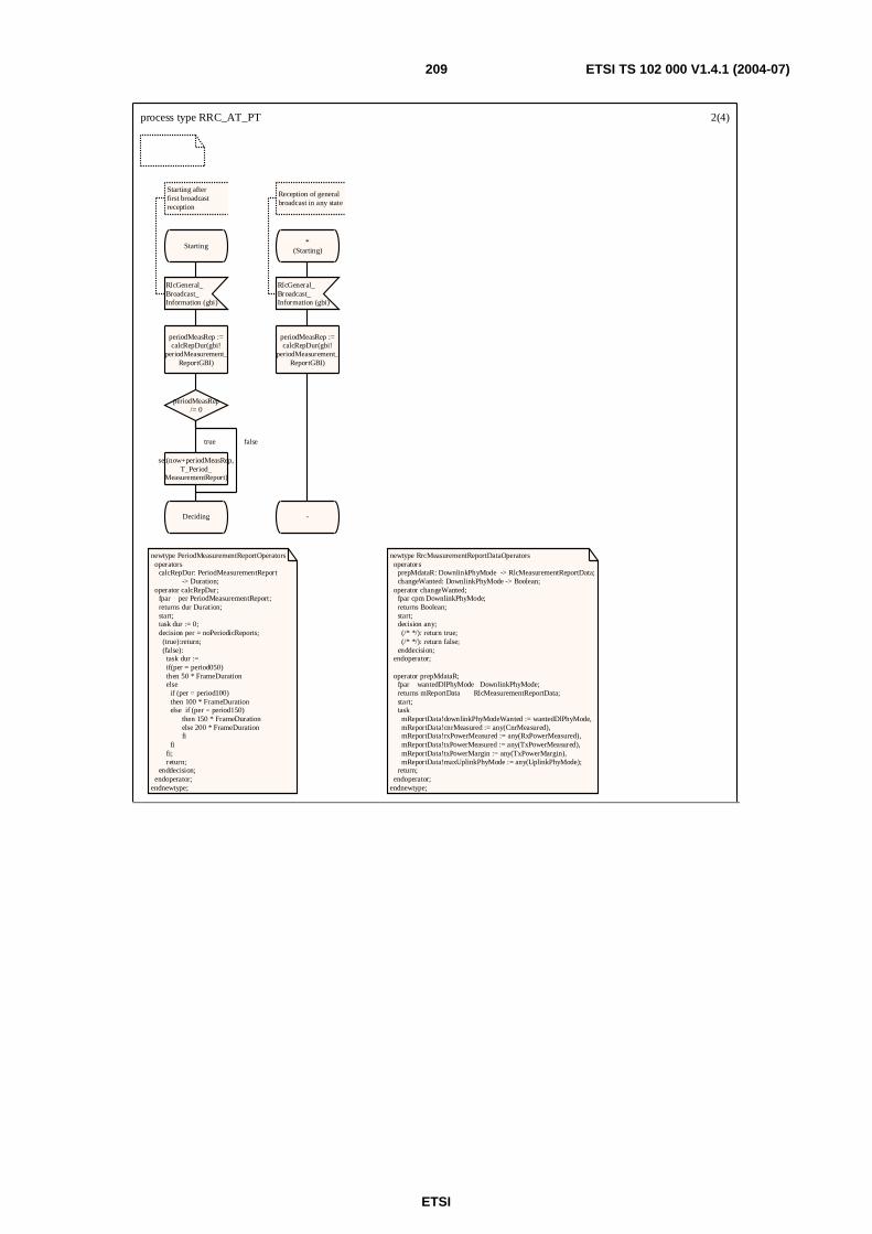
ETSI
ETSI TS 102 000 V1.4.1 (2004-07) 209
process type RRC_AT_PT 2(4)
newtype PeriodMeasurementReportOperators operators calcRepDur: PeriodMeasurementReport -> Duration; operator calcRepDur; fpar per PeriodMeasurementReport; returns dur Duration; start; task dur := 0; decision per = noPeriodicReports; (true):return; (false): task dur := if(per = period050) then 50 * FrameDuration else if (per = period100) then 100 * FrameDuration else if (per = period150) then 150 * FrameDuration else 200 * FrameDuration fi fi fi; return; enddecision; endoperator;endnewtype;
newtype RrcMeasurementReportDataOperators operators prepMdataR: DownlinkPhyMode -> RlcMeasurementReportData; changeWanted: DownlinkPhyMode -> Boolean; operator changeWanted; fpar cpm DownlinkPhyMode; returns Boolean; start; decision any; (/* */): return true; (/* */): return false; enddecision; endoperator; operator prepMdataR; fpar wantedDlPhyMode DownlinkPhyMode; returns mReportData RlcMeasurementReportData; start; task mReportData!downlinkPhyModeWanted := wantedDlPhyMode, mReportData!cnrMeasured := any(CnrMeasured), mReportData!rxPowerMeasured := any(RxPowerMeasured), mReportData!txPowerMeasured := any(TxPowerMeasured), mReportData!txPowerMargin := any(TxPowerMargin), mReportData!maxUplinkPhyMode := any(UplinkPhyMode); return; endoperator;endnewtype;
Starting
RlcGeneral_Broadcast_Information (gbi)
Starting afterfirst broadcastreception
periodMeasRep :=calcRepDur(gbi!
periodMeasurement_ReportGBI)
periodMeasRep/= 0
set(now+periodMeasRep,T_Period_
MeasurementReport)
Deciding
*(Starting)
RlcGeneral_Broadcast_Information (gbi)
Reception of generalbroadcast in any state
periodMeasRep :=calcRepDur(gbi!
periodMeasurement_ReportGBI)
-
true false

ETSI
ETSI TS 102 000 V1.4.1 (2004-07) 210
process type RRC_AT_PT 3(4)
Deciding
None
C/(N+I) threshold in received DL signal crossed
wantedDlPhyMode:= choosePM(dlPhyMode)
mReportData :=prepMdataR
(wantedDlPhyMode)
RlcMeasurement_ReportData(mReportData)
SET(T_Measurement_
ReportData)
set(now+periodMeasRep,T_Period_
MeasurementReport)
set(T_end)
RlcMeasurement_ReportData_
Sent
T_Period_MeasurementReport
mReportData :=prepMdataR
(noNewPhyMode)
RlcMeasurement_ReportData(mReportData)
set(now+periodMeasRep,T_Period_
MeasurementReport)
Deciding
RlcUplinkCorrection(ulCorrection)
'correct UL powerand timing'
ulCorrection!measurement_
ReportReq
= measurementReport_RequestedYes
Deciding
changeWanted(dlPhyMode)
mReportData :=prepMdataR
(noNewPhyMode)
RlcMeasurement_ReportData(mReportData)
set(now+periodMeasRep,T_Period_
MeasurementReport)
Deciding
wantedDlPhyMode:= choosePM(dlPhyMode)
mReportData :=prepMdataR
(wantedDlPhyMode)
RlcMeasurement_ReportData(mReportData)
SET(T_Measurement_
ReportData)
set(now+periodMeasRep,T_Period_
MeasurementReport)
RlcMeasurement_ReportData_
Sent
*(Starting)
RlcMeasurementReport_Criterium(mCriterium)
periodMeasRep :=calcRepDur(mCriterium!periodMeasurement_ReportAtSpecific)
-
falsetrue
false true
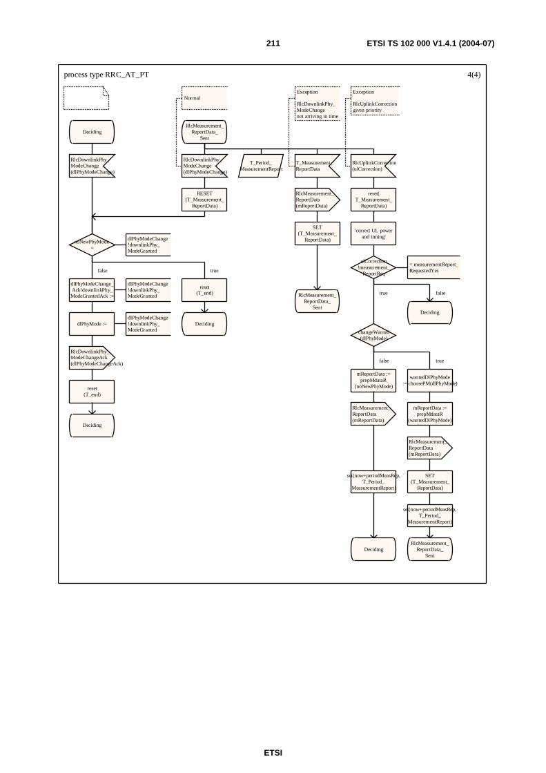
ETSI
ETSI TS 102 000 V1.4.1 (2004-07) 211
process type RRC_AT_PT 4(4)
Deciding
RlcDownlinkPhy_ModeChange(dlPhyModeChange)
noNewPhyMode =
dlPhyModeChange!downlinkPhy_ModeGranted
dlPhyModeChange_Ack!downlinkPhy_
ModeGrantedAck :=
dlPhyModeChange!downlinkPhy_ModeGranted
dlPhyMode :=dlPhyModeChange!downlinkPhy_ModeGranted
RlcDownlinkPhy_ModeChangeAck(dlPhyModeChangeAck)
reset(T_end)
Deciding
reset(T_end)
Deciding
RlcMeasurement_ReportData_
Sent
RlcDownlinkPhy_ModeChange(dlPhyModeChange)
Normal
RESET(T_Measurement_
ReportData)
T_Period_MeasurementReport
T_Measurement_ReportData
Exception
RlcDownlinkPhy_ModeChangenot arriving in time
RlcMeasurement_ReportData(mReportData)
SET(T_Measurement_
ReportData)
RlcMeasurement_ReportData_
Sent
RlcUplinkCorrection(ulCorrection)
Exception
RlcUplinkCorrectiongiven priority
reset(T_Measurement_
ReportData)
'correct UL powerand timing'
ulCorrection!measurement_
ReportReq
= measurementReport_RequestedYes
Deciding
changeWanted(dlPhyMode)
mReportData :=prepMdataR
(noNewPhyMode)
RlcMeasurement_ReportData(mReportData)
set(now+periodMeasRep,T_Period_
MeasurementReport)
Deciding
wantedDlPhyMode:= choosePM(dlPhyMode)
mReportData :=prepMdataR
(wantedDlPhyMode)
RlcMeasurement_ReportData(mReportData)
SET(T_Measurement_
ReportData)
set(now+periodMeasRep,T_Period_
MeasurementReport)
RlcMeasurement_ReportData_
Sent
false true
falsetrue
false true

ETSI
ETSI TS 102 000 V1.4.1 (2004-07) 212
E.3 Initialization control SDL model The initialization control model uses several SDL signals that in principle match the protocol messages. However, there are two exceptions worth mentioning:
• RangingGrant signal is used to simulate to the AT side that the AP has given an Ranging grant.
• EmptyGrant signal is used to simulate to the AP side that there is no content in the place for which an Ranging grant was given.
E.3.1 IC AP
process type InitializationAP 1(12)
/* This page shows process gates as means ofcommunicating with other entities */
IC_AP
InitializationSuccess
Initialize
IC_RLC_in
(UL_IC)
IC_RLC_out(DL_IC)

ETSI
ETSI TS 102 000 V1.4.1 (2004-07) 213
process type InitializationAP 2(12)
/* Specification of local timers */
TIMER T_RangingAck := RangingAckDuration; TIMER T_PhyCapabilitiesReq := PhyCapabilitiesReqDuration;TIMER T_PhyCapabilitiesCnf := PhyCapabilitiesCnfDuration;TIMER T_OtherCapabilitiesReq := OtherCapabilitiesReqDuration;TIMER T_OtherCapabilitiesCnf := OtherCapabilitiesCnfDuration;
/* Specification of local variables */
DCLrangingInvitation RlcRangingInvitation,rangingReq RlcRangingReq,rangingContinue RlcRangingContinue,rangingSuccess RlcRangingSuccess,rangingAck RlcRangingAck,phyCapabilitiesReq RlcPhyCapabilitiesReq,phyCapabilitiesInfo RlcPhyCapabilitiesInfo,phyCapabilitiesCnf RlcPhyCapabilitiesCnf,otherCapabilitiesReq RlcOtherCapabilitiesReq,otherCapabilitiesInfo RlcOtherCapabilitiesInfo,otherCapabilitiesCnf RlcOtherCapabilitiesCnf,initializationCmd RlcInitializationCmd;
DCL rangingResponseKind RangingResponseKind;DCL rangingAckOK RangingAckOK;DCL gbi RlcGeneralBroadcastInformation;DCL timingAdjust TimingAdjustRanging;DCL powerInc UplinkPowerInc;
DCL phyCapNeeded Boolean;DCL authNeeded Boolean;DCL otherCapNeeded Boolean;DCL iStatus InitializationStatus;
/* Some special timers used only for modellingpurposes. These place no normative requirements on theimplementations */
TIMER T_GBI := GbiDuration; /* Not mandatory, used in the model to show regular sending of RlcGeneralBroadcastInformation messages */
TIMER T_AdjustingDelayGrant := T_AdjustingDelayGrantDuration;TIMER T_SuccessDelayGrant := T_SuccessDelayGrantDuration;

ETSI
ETSI TS 102 000 V1.4.1 (2004-07) 214
process type InitializationAP 3(12)
/* Procedures used in AP by the Initialization process */
/* Start of the initialization proccess for the first time */
/* The sending of RlcGeneralBroadcastInformationcan be done in any state */
startAPactivities Starting regular broadcast
prepGBI Prepare the content of RlcGeneralBroacastInformationMessageJust a simplified indication that it needsto be done
determineRangingResponseA simplified procedure that indicates whatkind of responses can be given to RlcRangingRequest messages
rangingAckValidA simplified procedure that indicates whatkind of responses can be given to RlcRangingAck messages
PhyCapabilitiesNegotiationNeeded A simplified procedure that models the AP decision to do PhyCapabilitiesNegotiation or to skip it
AuthenticationNeeded A simplified procedure that models the AP decision to do Authentication or to skip it
OtherCapabilitiesNegotiationNeeded A simplified procedure that models the AP decision to do OtherCapabilitiesNegotiation or to skip it
start_APactivities
Idle
*In all states the the RlcGeneralBroadcastInformationmay be sent
T_GBI
RlcGeneralBroad_castInformation( CALL prepGBI)
modelling the GBIsending
set(T_GBI)
- Stay in the same state
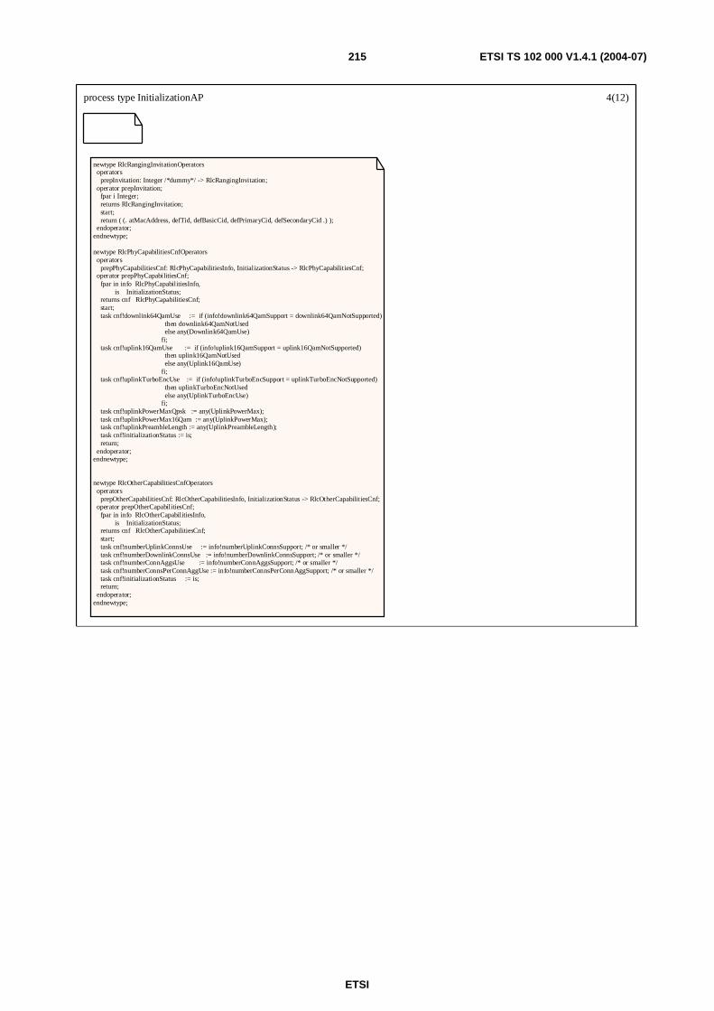
ETSI
ETSI TS 102 000 V1.4.1 (2004-07) 215
process type InitializationAP 4(12)
newtype RlcRangingInvitationOperators operators prepInvitation: Integer /*dummy*/ -> RlcRangingInvitation; operator prepInvitation; fpar i Integer; returns RlcRangingInvitation; start; return ( (. atMacAddress, defTid, defBasicCid, defPrimaryCid, defSecondaryCid .) ); endoperator;endnewtype;
newtype RlcPhyCapabilitiesCnfOperators operators prepPhyCapabilitiesCnf: RlcPhyCapabilitiesInfo, InitializationStatus -> RlcPhyCapabilitiesCnf; operator prepPhyCapabilitiesCnf; fpar in info RlcPhyCapabilitiesInfo, is InitializationStatus; returns cnf RlcPhyCapabilitiesCnf; start; task cnf!downlink64QamUse := if (info!downlink64QamSupport = downlink64QamNotSupported) then downlink64QamNotUsed else any(Downlink64QamUse) fi; task cnf!uplink16QamUse := if (info!uplink16QamSupport = uplink16QamNotSupported) then uplink16QamNotUsed else any(Uplink16QamUse) fi; task cnf!uplinkTurboEncUse := if (info!uplinkTurboEncSupport = uplinkTurboEncNotSupported) then uplinkTurboEncNotUsed else any(UplinkTurboEncUse) fi; task cnf!uplinkPowerMaxQpsk := any(UplinkPowerMax); task cnf!uplinkPowerMax16Qam := any(UplinkPowerMax); task cnf!uplinkPreambleLength := any(UplinkPreambleLength); task cnf!initializationStatus := is; return; endoperator;endnewtype;
newtype RlcOtherCapabilitiesCnfOperators operators prepOtherCapabilitiesCnf: RlcOtherCapabilitiesInfo, InitializationStatus -> RlcOtherCapabilitiesCnf; operator prepOtherCapabilitiesCnf; fpar in info RlcOtherCapabilitiesInfo, is InitializationStatus; returns cnf RlcOtherCapabilitiesCnf; start; task cnf!numberUplinkConnsUse := info!numberUplinkConnsSupport; /* or smaller */ task cnf!numberDownlinkConnsUse := info!numberDownlinkConnsSupport; /* or smaller */ task cnf!numberConnAggsUse := info!numberConnAggsSupport; /* or smaller */ task cnf!numberConnsPerConnAggUse := info!numberConnsPerConnAggSupport; /* or smaller */ task cnf!initializationStatus := is; return; endoperator;endnewtype;
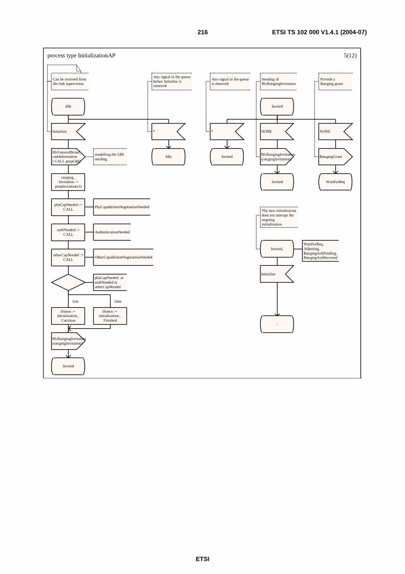
ETSI
ETSI TS 102 000 V1.4.1 (2004-07) 216
process type InitializationAP 5(12)
Idle
Initialize
Can be received from the link supervision
RlcGeneralBroad_castInformation( CALL prepGBI)
modelling the GBIsending
ranging_Invitation :=
prepInvitation(1)
phyCapNeeded :=CALL
PhyCapabilitiesNegotiationNeeded
authNeeded :=CALL
AuthenticationNeeded
otherCapNeeded :=CALL
OtherCapabilitiesNegotiationNeeded
phyCapNeeded orauthNeeded orotherCapNeeded
iStatus := initialization_
Continue
RlcRangingInvitation(rangingInvitation)
Invited
iStatus := initialization_
Finished
*
Any signal in the queuebefore Initialize isremoved
Idle
Invited
*
Any signal in the queueis removed
Invited
NONE
RlcRangingInvitation(rangingInvitation)
Sending ofRlcRangingInvitation
Invited
NONE
RangingGrant
Provide aRanging grant
WaitForReq
Invited,
The new initializationdoes not interupt theongoinginitialization
WaitForReq,Adjusting,RangingAckPending,RangingAckReceived
Initialize
-
true false
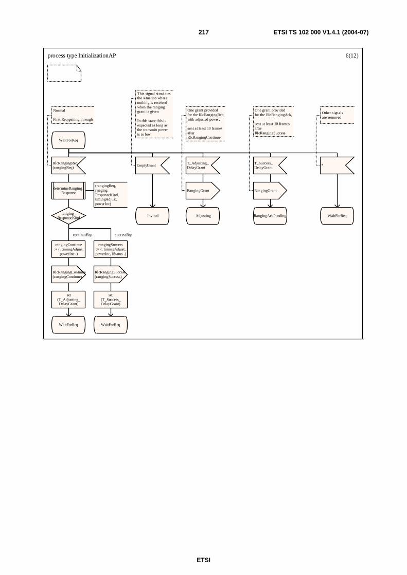
ETSI
ETSI TS 102 000 V1.4.1 (2004-07) 217
process type InitializationAP 6(12)
WaitForReq
RlcRangingReq(rangingReq)
Normal
First Req getting through
determineRanging_Response
(rangingReq, ranging_ResponseKind, timingAdjust,powerInc)
ranging_ResponseKind
rangingContinue:= (. timingAdjust,
powerInc .)
RlcRangingContinue(rangingContinue)
set(T_Adjusting_DelayGrant)
WaitForReq
rangingSuccess:= (. timingAdjust,powerInc, iStatus .)
RlcRangingSuccess(rangingSuccess)
set(T_Success_DelayGrant)
WaitForReq
EmptyGrant
This signal simulates the situation where nothing is received when the ranging grant is given
In this state this is expected as long as the transmitt poweris to low
Invited
T_Adjusting_DelayGrant
RangingGrant
One grant providedfor the RlcRangingReqwith adjusted power,
sent at least 10 framesafter RlcRangingContinue
Adjusting
T_Success_DelayGrant
RangingGrant
One grant providedfor the RlcRangingAck,
sent at least 10 framesafter RlcRangingSuccess
RangingAckPending
*
Other signalsare removed
WaitForReq
continueRsp successRsp
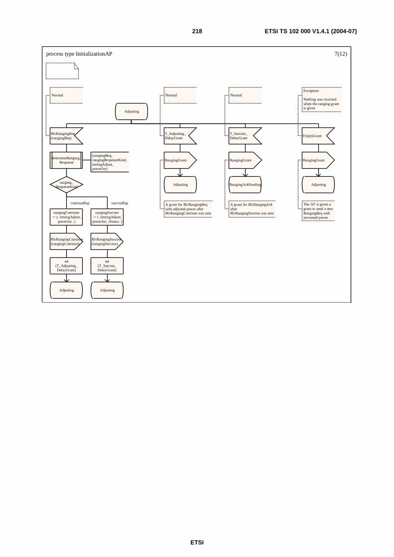
ETSI
ETSI TS 102 000 V1.4.1 (2004-07) 218
process type InitializationAP 7(12)
Adjusting
RlcRangingReq(rangingReq)
Normal
determineRanging_Response
(rangingReq, rangingResponseKind, timingAdjust,powerInc)
ranging_ResponseKind
rangingContinue:= (. timingAdjust,
powerInc .)
RlcRangingContinue(rangingContinue)
set(T_Adjusting_DelayGrant)
Adjusting
rangingSuccess:= (. timingAdjust,powerInc, iStatus .)
RlcRangingSuccess(rangingSuccess)
set(T_Success_DelayGrant)
Adjusting
T_Adjusting_DelayGrant
Normal
RangingGrant
A grant for RlcRangingReqwith adjusted power afterRlcRangingContinue was sent
Adjusting
T_Success_DelayGrant
Normal
RangingGrant
A grant for RlcRangingAckafterRlcRangingSuccess was sent
RangingAckPending
EmptyGrant
Exception
Nothing was receivedwhen the ranging grant is given
RangingGrant
The AT is given agrant to send a newRangingReq withincreased power
Adjusting
continueRsp successRsp
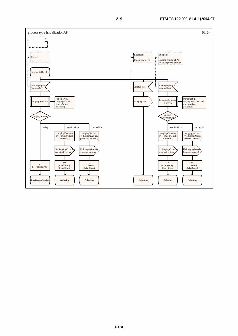
ETSI
ETSI TS 102 000 V1.4.1 (2004-07) 219
process type InitializationAP 8(12)
RangingAckPending
RlcRangingAck(rangingAck)
Normal
rangingAckValid(rangingAck, rangingAckOK, timingAdjust,powerInc)
rangingAckOK
rangingContinue:= (. timingAdjust,
powerInc .)
RlcRangingContinue(rangingContinue)
set(T_Adjusting_DelayGrant)
Adjusting
rangingSuccess:= (. timingAdjust,powerInc, iStatus .)
RlcRangingSuccess(rangingSuccess)
set(T_Success_DelayGrant)
Adjusting
set(T_RangingAck)
RangingAckReceived
EmptyGrant
Exception
RangingAck lost
RangingGrant
Adjusting
RlcRangingReq(rangingReq)
Exception
Success is lost and ATrestarted power increase
determineRanging_Response
(rangingReq, rangingResponseKind, timingAdjust,powerInc)
ranging_ResponseKind
rangingContinue:= (. timingAdjust,
powerInc .)
RlcRangingContinue(rangingContinue)
set(T_Adjusting_DelayGrant)
Adjusting
rangingSuccess:= (. timingAdjust,powerInc, iStatus .)
RlcRangingSuccess(rangingSuccess)
set(T_Success_DelayGrant)
Adjusting
continueRsp successRspokRsp continueRsp successRsp

ETSI
ETSI TS 102 000 V1.4.1 (2004-07) 220
process type InitializationAP 9(12)RangingAck_
Received
T_RangingAck
phyCapNeeded
authNeeded
otherCapNeeded
RlcOtherCapabilitiesReq(otherCapabilitiesReq)
set(T_Other_CapabilitiesReq)
iStatus := initialization_
Finished
OtherCapReq_Sent
InitializationSuccess
IdleAuthStart
RlcPhyCapabilitiesReq(phyCapabilitiesReq)
set(T_Phy_CapabilitiesReq)
authNeeded orotherCapNeeded
iStatus := initialization_
Continue
PhyCapReq_Sent
iStatus := initialization_
Finished
AuthStart
false
false
true
false
true
true
true false
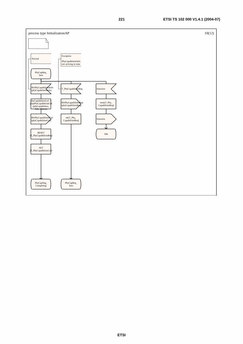
ETSI
ETSI TS 102 000 V1.4.1 (2004-07) 221
process type InitializationAP 10(12)
PhyCapReq_Sent
RlcPhyCapabilitiesInfo(phyCapabilitiesInfo)
Normal
phyCapabilitiesCnf :=prepPhyCapabilitiesCnf
(phyCapabilities_Info, iStatus)
RlcPhyCapabilitiesCnf(phyCapabilitiesCnf)
RESET(T_PhyCapabilitiesReq)
SET(T_PhyCapabilitiesCnf)
PhyCapNeg_Completing
T_PhyCapabilitiesReq
Exception
PhyCapabilitiesInfonot arriving in time
RlcPhyCapabilitiesReq(phyCapabilitiesReq)
set(T_Phy_CapabilitiesReq)
PhyCapReq_Sent
Initialize
reset(T_Phy_CapabilitiesReq)
Initialize
Idle
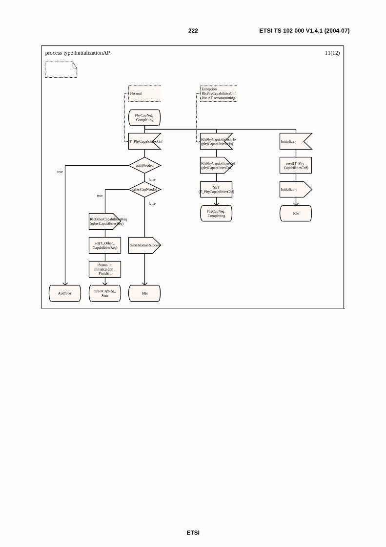
ETSI
ETSI TS 102 000 V1.4.1 (2004-07) 222
process type InitializationAP 11(12)
PhyCapNeg_Completing
T_PhyCapabilitiesCnf
Normal
authNeeded
otherCapNeeded
RlcOtherCapabilitiesReq(otherCapabilitiesReq)
set(T_Other_CapabilitiesReq)
iStatus := initialization_
Finished
OtherCapReq_Sent
InitializationSuccess
IdleAuthStart
RlcPhyCapabilitiesInfo(phyCapabilitiesInfo)
ExceptionRlcPhyCapabilitiesCnflost AT retransmitting
RlcPhyCapabilitiesCnf(phyCapabilitiesCnf)
SET(T_PhyCapabilitiesCnf)
PhyCapNeg_Completing
Initialize
reset(T_Phy_CapabilitiesCnf)
Initialize
Idle
false
true
false
true
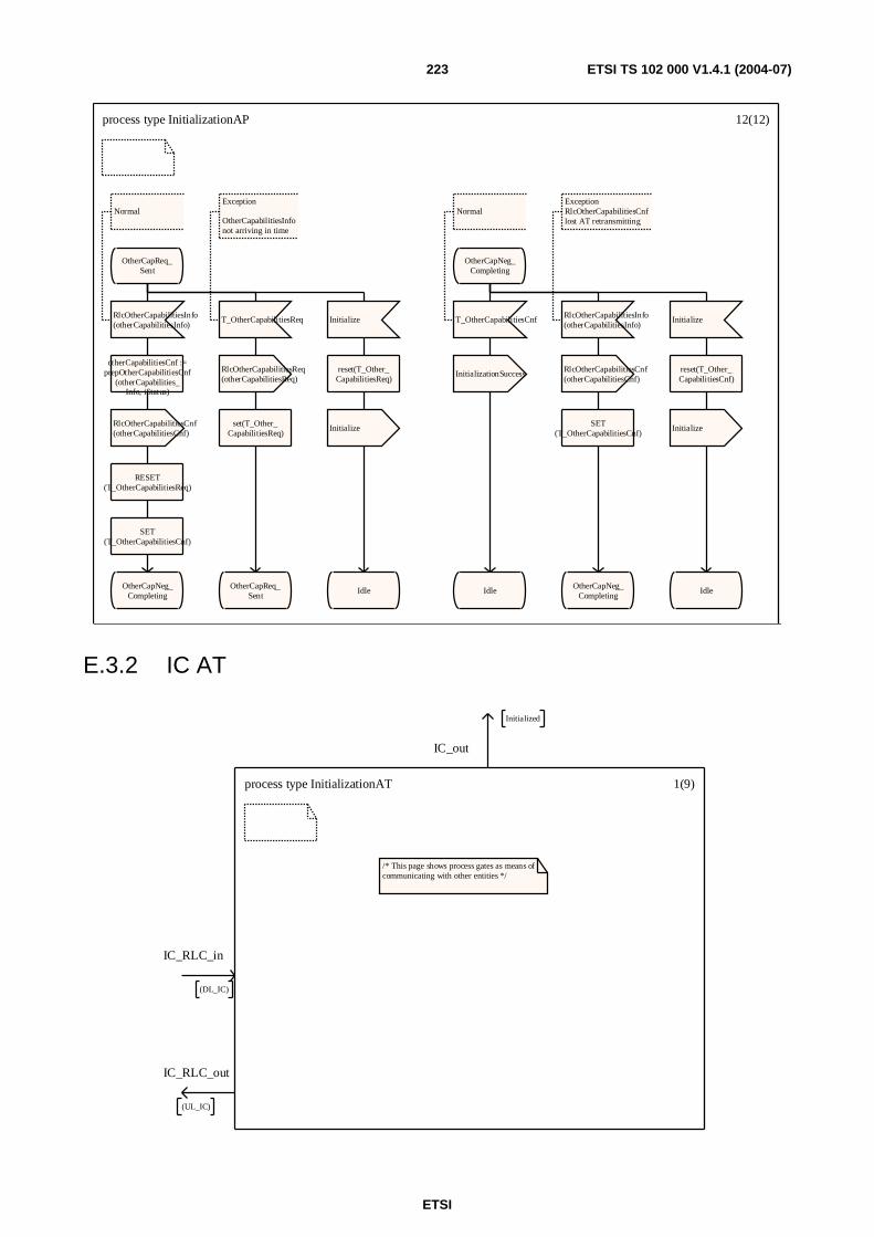
ETSI
ETSI TS 102 000 V1.4.1 (2004-07) 223
process type InitializationAP 12(12)
OtherCapReq_Sent
RlcOtherCapabilitiesInfo(otherCapabilitiesInfo)
Normal
otherCapabilitiesCnf :=prepOtherCapabilitiesCnf
(otherCapabilities_Info, iStatus)
RlcOtherCapabilitiesCnf(otherCapabilitiesCnf)
RESET(T_OtherCapabilitiesReq)
SET(T_OtherCapabilitiesCnf)
OtherCapNeg_Completing
T_OtherCapabilitiesReq
Exception
OtherCapabilitiesInfonot arriving in time
RlcOtherCapabilitiesReq(otherCapabilitiesReq)
set(T_Other_CapabilitiesReq)
OtherCapReq_Sent
Initialize
reset(T_Other_CapabilitiesReq)
Initialize
Idle
OtherCapNeg_Completing
T_OtherCapabilitiesCnf
Normal
InitializationSuccess
Idle
RlcOtherCapabilitiesInfo(otherCapabilitiesInfo)
ExceptionRlcOtherCapabilitiesCnflost AT retransmitting
RlcOtherCapabilitiesCnf(otherCapabilitiesCnf)
SET(T_OtherCapabilitiesCnf)
OtherCapNeg_Completing
Initialize
reset(T_Other_CapabilitiesCnf)
Initialize
Idle
E.3.2 IC AT
process type InitializationAT 1(9)
/* This page shows process gates as means ofcommunicating with other entities */
IC_out
Initialized
IC_RLC_in
(DL_IC)
IC_RLC_out
(UL_IC)
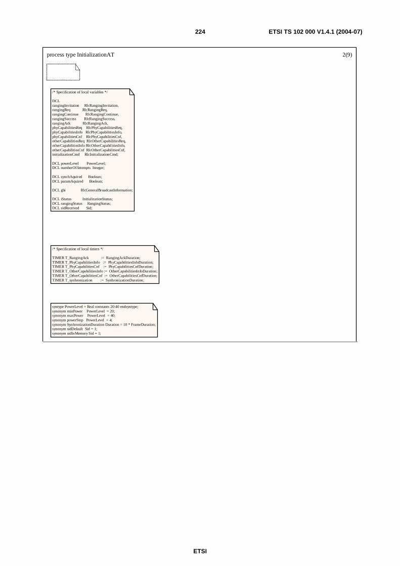
ETSI
ETSI TS 102 000 V1.4.1 (2004-07) 224
process type InitializationAT 2(9)
/* Specification of local variables */
DCLrangingInvitation RlcRangingInvitation,rangingReq RlcRangingReq,rangingContinue RlcRangingContinue,rangingSuccess RlcRangingSuccess,rangingAck RlcRangingAck,phyCapabilitiesReq RlcPhyCapabilitiesReq,phyCapabilitiesInfo RlcPhyCapabilitiesInfo,phyCapabilitiesCnf RlcPhyCapabilitiesCnf,otherCapabilitiesReq RlcOtherCapabilitiesReq,otherCapabilitiesInfo RlcOtherCapabilitiesInfo,otherCapabilitiesCnf RlcOtherCapabilitiesCnf,initializationCmd RlcInitializationCmd;
DCL powerLevel PowerLevel;DCL numberOfAttempts Integer;
DCL synchAquired Boolean;DCL paramAquired Boolean;
DCL gbi RlcGeneralBroadcastInformation;
DCL iStatus InitializationStatus;DCL rangingStatus RangingStatus;DCL sidReceived Sid;
/* Specification of local timers */
TIMER T_RangingAck := RangingAckDuration;TIMER T_PhyCapabilitiesInfo := PhyCapabilitiesInfoDuration;TIMER T_PhyCapabilitiesCnf := PhyCapabilitiesCnfDuration;TIMER T_OtherCapabilitiesInfo := OtherCapabilitiesInfoDuration;TIMER T_OtherCapabilitiesCnf := OtherCapabilitiesCnfDuration;TIMER T_synhronization := SynhronizationDuration;
syntype PowerLevel = Real constants 20:40 endsyntype;synonym minPower PowerLevel = 20;synonym maxPower PowerLevel = 40;synonym powerStep PowerLevel = 4;synonym SynhronizationDuration Duration = 10 * FrameDuration;synonym sidDefault Sid = 1;synonym sidInMemory Sid = 1;
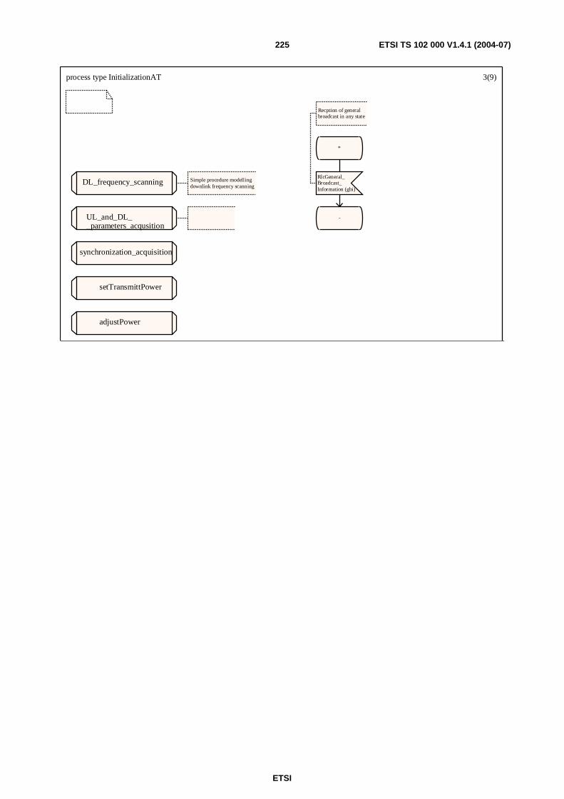
ETSI
ETSI TS 102 000 V1.4.1 (2004-07) 225
process type InitializationAT 3(9)
*
RlcGeneral_Broadcast_Information (gbi)
Recption of generalbroadcast in any state
-
DL_frequency_scanning Simple procedure modellingdownlink frequency scanning
UL_and_DL__parameters_acqusition
synchronization_acquisition
setTransmittPower
adjustPower
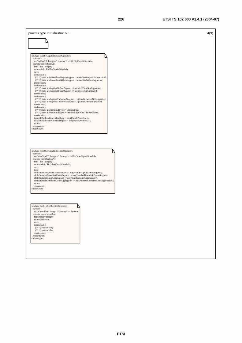
ETSI
ETSI TS 102 000 V1.4.1 (2004-07) 226
process type InitializationAT 4(9)
newtype RlcPhyCapabilitiesInfoOperators operators setPhyCapAT: Integer /* dummy */ -> RlcPhyCapabilitiesInfo; operator setPhyCapAT; fpar int Integer; returns info RlcPhyCapabilitiesInfo; start; decision any; (/* */): task info!downlink64QamSupport := downlink64QamNotSupported; (/* */): task info!downlink64QamSupport := downlink64QamSupported; enddecision; decision any; (/* */): task info!uplink16QamSupport := uplink16QamNotSupported; (/* */): task info!uplink16QamSupport := uplink16QamSupported; enddecision; decision any; (/* */): task info!uplinkTurboEncSupport := uplinkTurboEncNotSupported; (/* */): task info!uplinkTurboEncSupport := uplinkTurboEncSupported; enddecision; decision any; (/* */): task info!terminalType := terminalFdd; (/* */): task info!terminalType := terminalHfddWithTdmAndTdma; enddecision; task info!uplinkPowerMaxQpsk := any(UplinkPowerMax); task info!uplinkPowerMax16Qam := any(UplinkPowerMax); return; endoperator;endnewtype;
newtype RlcOtherCapabilitiesInfoOperators operators setOtherCapAT: Integer /* dummy */ -> RlcOtherCapabilitiesInfo; operator setOtherCapAT; fpar int Integer; returns oInfo RlcOtherCapabilitiesInfo; start; task oInfo!numberUplinkConnsSupport := any(NumberUplinkConnsSupport), oInfo!numberDownlinkConnsSupport := any(NumberDownlinkConnsSupport), oInfo!numberConnAggsSupport := any(NumberConnAggsSupport), oInfo!numberConnsPerConnAggSupport := any(NumberConnsPerConnAggSupport); return; endoperator;endnewtype;
newtype SectorIdentificationOperators operators sectorIdentified: Integer /*dummy*/ -> Boolean; operator sectorIdentified; fpar dummy Integer; returns Boolean; start; decision any; (/* */): return true; (/* */): return false; enddecision; endoperator;endnewtype;
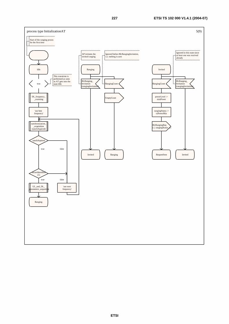
ETSI
ETSI TS 102 000 V1.4.1 (2004-07) 227
process type InitializationAT 5(9)
Start of the ranging proces for the first time
Idle
true
This transition is performed as soon as AT gets into thestate Idle
DL_frequency__scanning
'use best frequency'
synchronization__acquisition
(synchAquired)
synchAquired
sectorIdentified(1)
UL_and_DL__parameters_acqusition
Ranging
'use nextfrequency'
Ranging
RlcRanging_Invitation(rangingInvitation)
AP initiates the invited ranging
Invited
RangingGrant
Ignored before RlcRangingInvitation,i.e. nothing is sent
EmptyGrant
Ranging
Invited
RangingGrant
powerLevel :=minPower
rangingStatus :=txPowerMin
RlcRangingReq( (. rangingStatus .) )
RequestSent
RlcRanging_Invitation(rangingInvitation)
Ignored in this state sinceat least one was receivedalready
Invited
true
true false
false
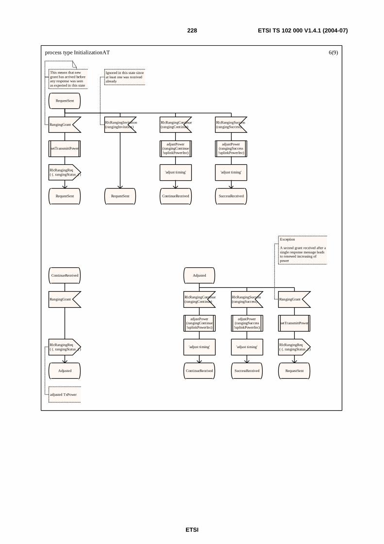
ETSI
ETSI TS 102 000 V1.4.1 (2004-07) 228
process type InitializationAT 6(9)
RequestSent
RangingGrant
This means that newgrant has arrived before any response was seenas expected in this state
setTransmittPower
RlcRangingReq( (. rangingStatus .) )
RequestSent
RlcRangingInvitation(rangingInvitation)
Ignored in this state sinceat least one was receivedalready
RequestSent
RlcRangingContinue(rangingContinue)
adjustPower(rangingContinue!uplinkPowerInc)
'adjust timing'
ContinueReceived
RlcRangingSuccess(rangingSuccess)
adjustPower(rangingSuccess!uplinkPowerInc)
'adjust timing'
SuccessReceived
ContinueReceived
RangingGrant
RlcRangingReq( (. rangingStatus .) )
adjusted TxPower
Adjusted
Adjusted
RlcRangingContinue(rangingContinue)
adjustPower(rangingContinue!uplinkPowerInc)
'adjust timing'
ContinueReceived
RlcRangingSuccess(rangingSuccess)
adjustPower(rangingSuccess!uplinkPowerInc)
'adjust timing'
SuccessReceived
RangingGrant
Exception
A second grant received after asingle response message leadsto renewed increasing ofpower
setTransmittPower
RlcRangingReq( (. rangingStatus .) )
RequestSent

ETSI
ETSI TS 102 000 V1.4.1 (2004-07) 229
process type InitializationAT 7(9)
SuccessReceived
RangingGrant
rangingAck :=(. rangingStatus .)
RlcRangingAck(rangingAck)
set(T_RangingAck)
RangingCompleting
RangingCompleting
T_RangingAck
Normal
RangingCompleted
RlcRangingContinue(rangingContinue)
reset(T_RangingAck)
adjustPower(rangingContinue!uplinkPowerInc)
'adjust timing'
ContinueReceived
RlcRangingSuccess(rangingSuccess)
reset(T_RangingAck)
adjustPower(rangingSuccess!uplinkPowerInc)
'adjust timing'
SuccessReceived
RangingGrant
Exception
A second grant received after asingle response message leadsto renewed inclreasing ofpower
reset(T_RangingAck)
setTransmittPower
RlcRangingReq(rangingReq)
RequestSent
RangingCompleted
RlcPhy_CapabilitiesReq(phyCapabilitiesReq)
phyCapabilitiesInfo :=setPhyCapAT(1)
RlcPhy_CapabilitiesInfo(phyCapabilitiesInfo)
set(T_Phy_CapabilitiesInfo)
PhyCapabilities_InfoSent
RlcRanging_Invitation(rangingInvitation)
Invited
RangingCompleted
RlcOther_CapabilitiesReq(otherCapabilitiesReq)
otherCapabilitiesInfo :=setOtherCapAT(1)
RlcOther_CapabilitiesInfo(otherCapabilitiesInfo)
set(T_Other_CapabilitiesInfo)
OtherCapabilities_InfoSent
PhyCapabilities_Completing
RlcOther_CapabilitiesReq(otherCapabilitiesReq)
reset(T_Phy_CapabilitiesCnf)

ETSI
ETSI TS 102 000 V1.4.1 (2004-07) 230
process type InitializationAT 8(9)
PhyCapabilities_InfoSent
RlcPhyCapabilitiesCnf(phyCapabilitiesCnf)
Normal
reset(T_Phy_CapabilitiesInfo)
set(T_Phy_CapabilitiesCnf)
iStatus := phyCapabilitiesCnf!initializationStatus
PhyCapabilities_Completing
RlcRanging_Invitation(rangingInvitation)
reset(T_Phy_CapabilitiesInfo)
Invited
RlcPhyCapabilitiesReq(phyCapabilitiesReq)
Exception
AP retransmittingInfo lost
RlcPhyCapabilitiesInfo(phyCapabilitiesInfo)
set(T_Phy_CapabilitiesInfo)
PhyCapabilities_InfoSent
T_Phy_CapabilitiesInfo
Exception
RlcPhy_CapabilitiesCnfnot received in time
PhyCapabilities_Completing
T_Phy_CapabilitiesCnf
Normal
iStatus
RangingCompleted Ranging
RlcPhyCapabilitiesCnf(phyCapabilitiesCnf)
Exception
AP retransmitting Cnf
set(T_Phy_CapabilitiesCnf)
PhyCapabilities_Completing
RlcRanging_Invitation(rangingInvitation)
reset(T_Phy_CapabilitiesCnf)
Invited
initializationContinue initializationFinished
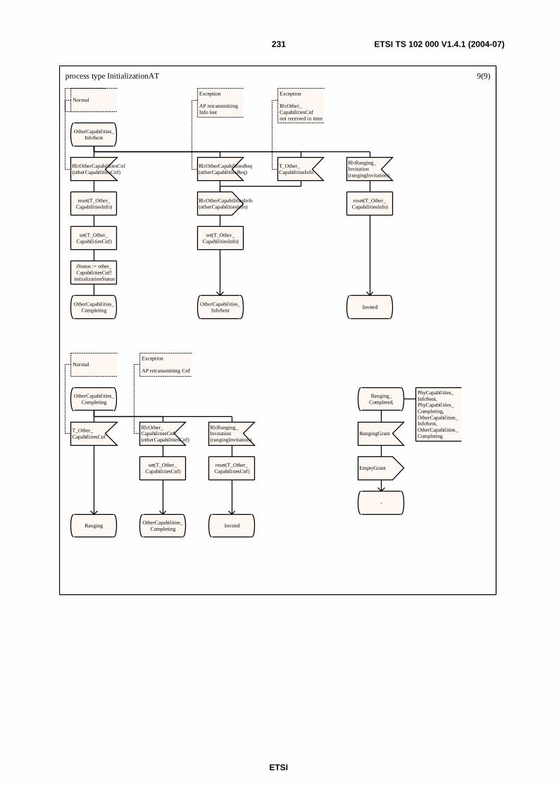
ETSI
ETSI TS 102 000 V1.4.1 (2004-07) 231
process type InitializationAT 9(9)
OtherCapabilities_InfoSent
RlcOtherCapabilitiesCnf(otherCapabilitiesCnf)
Normal
reset(T_Other_CapabilitiesInfo)
set(T_Other_CapabilitiesCnf)
iStatus := other_CapabilitiesCnf!
initializationStatus
OtherCapabilities_Completing
RlcOtherCapabilitiesReq(otherCapabilitiesReq)
Exception
AP retransmittingInfo lost
RlcOtherCapabilitiesInfo(otherCapabilitiesInfo)
set(T_Other_CapabilitiesInfo)
OtherCapabilities_InfoSent
T_Other_CapabilitiesInfo
Exception
RlcOther_CapabilitiesCnfnot received in time
RlcRanging_Invitation(rangingInvitation)
reset(T_Other_CapabilitiesInfo)
Invited
OtherCapabilities_Completing
T_Other_CapabilitiesCnf
Normal
Ranging
RlcOther_CapabilitiesCnf(otherCapabilitiesCnf)
Exception
AP retransmitting Cnf
set(T_Other_CapabilitiesCnf)
OtherCapabilities_Completing
RlcRanging_Invitation(rangingInvitation)
reset(T_Other_CapabilitiesCnf)
Invited
Ranging_Completed,
PhyCapabilities_InfoSent,PhyCapabilities_Completing,OtherCapabilities_InfoSent,OtherCapabilities_CompletingRangingGrant
EmptyGrant
-
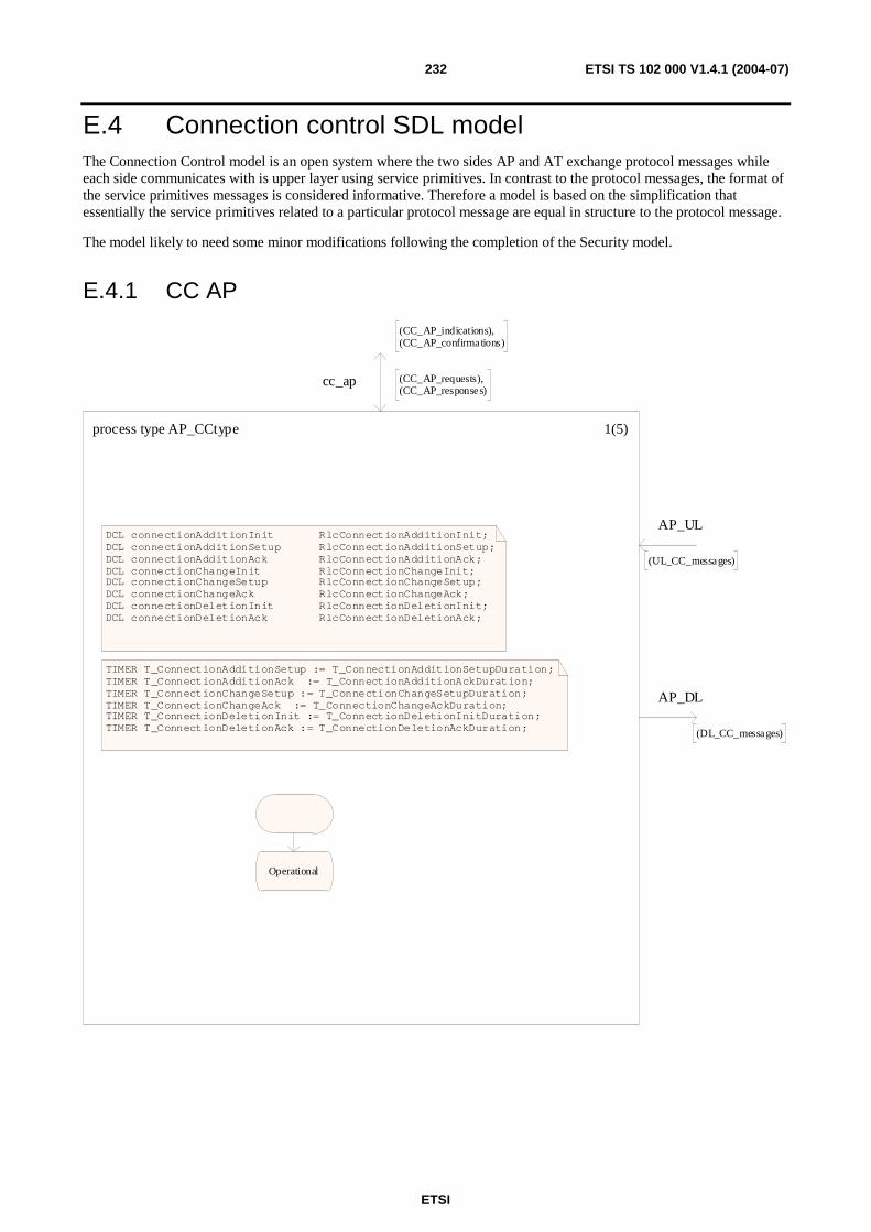
ETSI
ETSI TS 102 000 V1.4.1 (2004-07) 232
E.4 Connection control SDL model The Connection Control model is an open system where the two sides AP and AT exchange protocol messages while each side communicates with is upper layer using service primitives. In contrast to the protocol messages, the format of the service primitives messages is considered informative. Therefore a model is based on the simplification that essentially the service primitives related to a particular protocol message are equal in structure to the protocol message.
The model likely to need some minor modifications following the completion of the Security model.
E.4.1 CC AP
process type AP_CCtype 1(5)
DCL connectionAdditionInit RlcConnectionAdditionInit;DCL connectionAdditionSetup RlcConnectionAdditionSetup; DCL connectionAdditionAck RlcConnectionAdditionAck;DCL connectionChangeInit RlcConnectionChangeInit;DCL connectionChangeSetup RlcConnectionChangeSetup; DCL connectionChangeAck RlcConnectionChangeAck;DCL connectionDeletionInit RlcConnectionDeletionInit; DCL connectionDeletionAck RlcConnectionDeletionAck;
TIMER T_ConnectionAdditionSetup := T_ConnectionAdditionSetupDuration;TIMER T_ConnectionAdditionAck := T_ConnectionAdditionAckDuration;TIMER T_ConnectionChangeSetup := T_ConnectionChangeSetupDuration;TIMER T_ConnectionChangeAck := T_ConnectionChangeAckDuration;TIMER T_ConnectionDeletionInit := T_ConnectionDeletionInitDuration;TIMER T_ConnectionDeletionAck := T_ConnectionDeletionAckDuration;
Operational
cc_ap
(CC_AP_indications),(CC_AP_confirmations)
(CC_AP_requests),(CC_AP_responses)
AP_UL
(UL_CC_messages)
AP_DL
(DL_CC_messages)
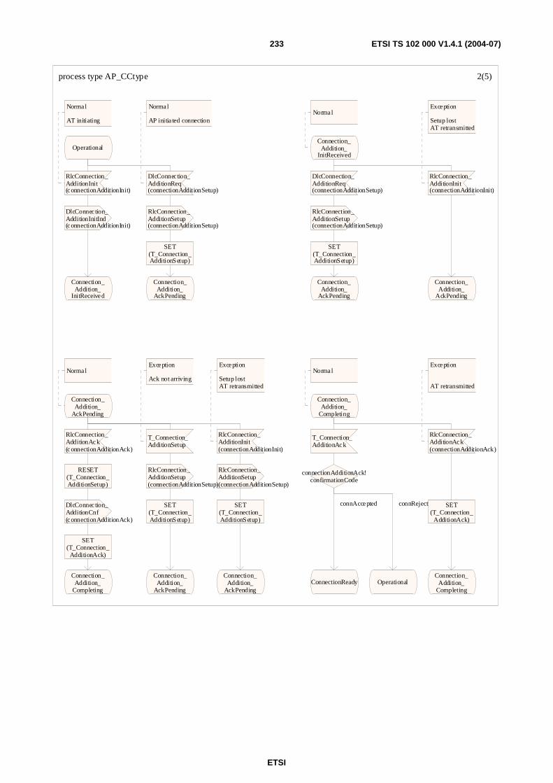
ETSI
ETSI TS 102 000 V1.4.1 (2004-07) 233
process type AP_CCtype 2(5)
Operational
RlcConnection_AdditionInit(connectionAdditionInit)
Normal
AT initiating
DlcConnec tion_AdditionInitInd(connectionAdditionInit)
Connection_Addition_
InitReceived
DlcConnec tion_AdditionReq(connectionAdditionSetup)
Normal
AP initia ted connection
RlcConnection_AdditionSetup(connectionAdditionSetup)
SET(T_Connection_AdditionSetup)
Connection_Addition_
AckPending
Connection_Addition_
InitReceived
Normal
DlcConnection_AdditionReq(connectionAdditionSetup)
RlcConnection_AdditionSetup(connectionAdditionSetup)
SET(T_Connection_AdditionSetup)
Connection_Addition_
AckPending
RlcConnection_AdditionInit(connectionAdditionInit)
Exception
Setup lostAT retransmitted
Connection_Addition_
AckPending
Connection_Addition_
AckPending
Normal
RlcConnection_AdditionAck(connectionAdditionAck)
RESET(T_Connection_AdditionSetup)
DlcConnec tion_AdditionCnf(connectionAdditionAck)
SET(T_Connection_
AdditionAck)
Connection_Addition_
Completing
T_Connection_AdditionSetup
Exception
Ack not arriving
RlcConnection_AdditionSetup(connectionAdditionSetup)
SET(T_Connection_AdditionSetup)
Connection_Addition_
AckPending
RlcConnection_AdditionInit(connectionAdditionInit)
Exception
Setup lostAT retransmitted
RlcConnection_AdditionSetup(connectionAdditionSetup)
SET(T_Connection_AdditionSetup)
Connection_Addition_
AckPending
Connection_Addition_
Completing
Normal
T_Connection_AdditionAck
connectionAdditionAck!confirmationCode
ConnectionReady Operational
RlcConnection_AdditionAck(connectionAdditionAck)
Exception
AT retransmitted
SET(T_Connection_
AdditionAck)
Connection_Addition_
Completing
connAccepted connReject
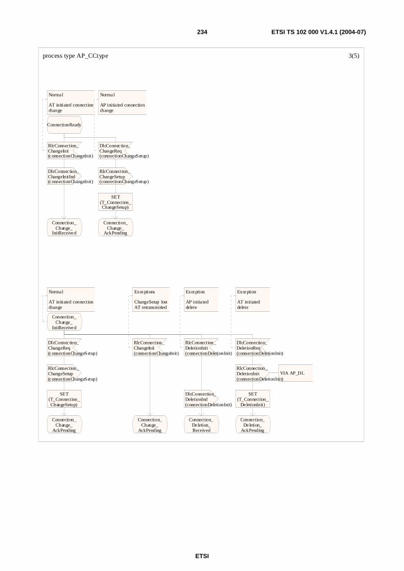
ETSI
ETSI TS 102 000 V1.4.1 (2004-07) 234
process type AP_CCtype 3(5)
ConnectionReady
RlcConnection_ChangeInit(connectionChangeInit)
Normal
AT initiated connectionchange
DlcConnec tion_ChangeInitInd(connectionChangeInit)
Connection_Change_
InitReceived
DlcConnec tion_ChangeReq(connectionChangeSetup)
Normal
AP initia ted connectionchange
RlcConnection_ChangeSetup(connectionChangeSetup)
SET(T_Connection_ChangeSetup)
Connection_Change_
AckPending
Connection_Change_
InitReceived
Normal
AT initiated connectionchange
DlcConnec tion_ChangeReq(connectionChangeSetup)
RlcConnection_ChangeSetup(connectionChangeSetup)
SET(T_Connection_ChangeSetup)
Connection_Change_
AckPending
RlcConnection_ChangeInit(connectionChangeInit)
Exceptions
ChangeSetup lostAT retransmitted
Connection_Change_
AckPending
RlcConnection_DeletionInit(connectionDeletionInit)
Exception
AP initiateddelete
DlcConnection_DeletionInd(connectionDeletionInit)
Connection_Deletion_Received
DlcConnection_DeletionReq(connectionDeletionInit)
Exception
AT initiateddelete
RlcConnection_DeletionInit(connectionDeletionInit)
VIA AP_DL
SET(T_Connection_
DeletionInit)
Connection_Deletion_
AckPending
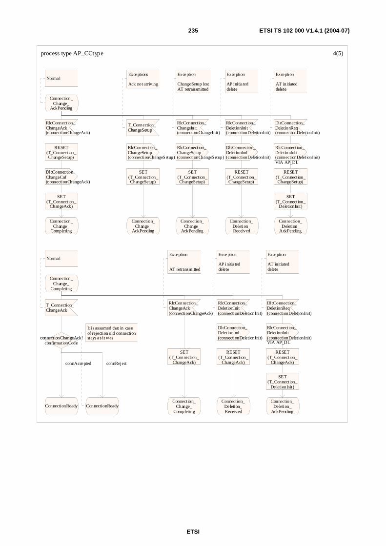
ETSI
ETSI TS 102 000 V1.4.1 (2004-07) 235
process type AP_CCtype 4(5)
Connection_Change_
AckPending
Normal
RlcConnection_ChangeAck(connectionChangeAck)
RESET(T_Connection_ChangeSetup)
DlcConnec tion_ChangeCnf(connectionChangeAck)
SET(T_Connection_
ChangeAck)
Connection_Change_
Completing
T_Connection_ChangeSetup
Exceptions
Ack not arriving
RlcConnection_ChangeSetup(connectionChangeSetup)
SET(T_Connection_ChangeSetup)
Connection_Change_
AckPending
RlcConnection_ChangeInit(connectionChangeInit)
Exception
ChangeSetup lostAT retransmitted
RlcConnection_ChangeSetup(connectionChangeSetup)
SET(T_Connection_ChangeSetup)
Connection_Change_
AckPending
RlcConnection_DeletionInit(connectionDeletionInit)
Exception
AP initia teddelete
DlcConnection_DeletionInd(connectionDeletionInit)
RESET(T_Connection_ChangeSetup)
Connection_Deletion_Received
DlcConnection_DeletionReq(connectionDeletionInit)
Exception
AT initiateddelete
RlcConnection_DeletionInit(connectionDeletionInit)VIA AP_DL
RESET(T_Connection_ChangeSetup)
SET(T_Connection_
DeletionInit)
Connection_Deletion_
AckPending
Connection_Change_
Completing
T_Connection_ChangeAck
Normal
connectionChangeAck!confirmationCode
ConnectionReady ConnectionReady
It is assumed that in case of rejection old connectionstays as it was
RlcConnection_ChangeAck(connectionChangeAck)
Exception
AT retransmitted
SET(T_Connection_
ChangeAck)
Connection_Change_
Completing
RlcConnection_DeletionInit(connectionDeletionInit)
Exception
AP initia teddelete
DlcConnection_DeletionInd(connectionDeletionInit)
RESET(T_Connection_
ChangeAck)
Connection_Deletion_Received
DlcConnection_DeletionReq(connectionDeletionInit)
Exception
AT initiateddelete
RlcConnection_DeletionInit(connectionDeletionInit)VIA AP_DL
RESET(T_Connection_
ChangeAck)
SET(T_Connection_
DeletionInit)
Connection_Deletion_
AckPending
connAccepted connReject
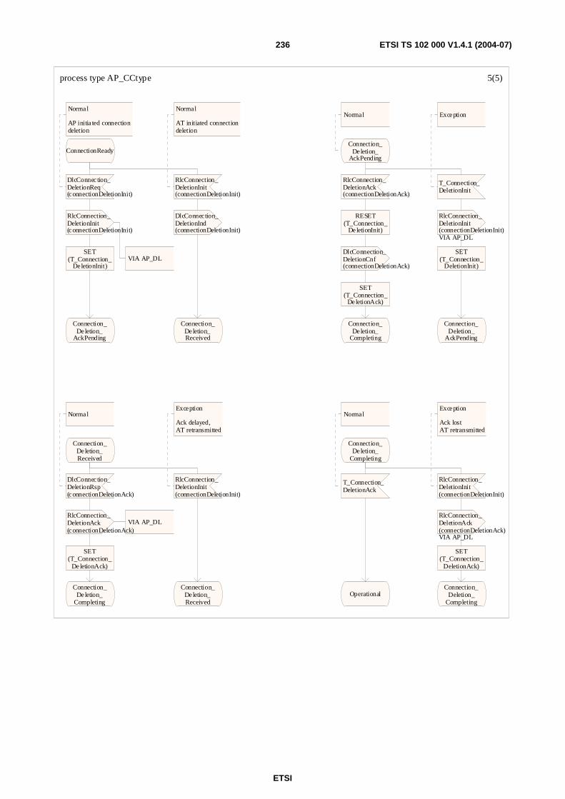
ETSI
ETSI TS 102 000 V1.4.1 (2004-07) 236
process type AP_CCtype 5(5)
ConnectionReady
DlcConnec tion_DeletionReq(connectionDeletionInit)
Normal
AP initia ted connectiondeletion
RlcConnection_DeletionInit(connectionDeletionInit)
VIA AP_DLSET
(T_Connection_DeletionInit)
Connection_Deletion_
AckPending
RlcConnection_DeletionInit(connectionDeletionInit)
Normal
AT initiated connectiondeletion
DlcConnection_DeletionInd(connectionDeletionInit)
Connection_Deletion_Received
Connection_Deletion_
AckPending
Normal
RlcConnection_DeletionAck(connectionDeletionAck)
RESET(T_Connection_
DeletionInit)
DlcConnection_DeletionCnf(connectionDeletionAck)
SET(T_Connection_
DeletionAck)
Connection_Deletion_
Completing
T_Connection_DeletionInit
Exception
RlcConnection_DeletionInit(connectionDeletionInit)VIA AP_DL
SET(T_Connection_
DeletionInit)
Connection_Deletion_
AckPending
Connection_Deletion_Received
DlcConnec tion_DeletionRsp(connectionDeletionAck)
Normal
RlcConnection_DeletionAck(connectionDeletionAck)
VIA AP_DL
SET(T_Connection_
DeletionAck)
Connection_Deletion_
Completing
RlcConnection_DeletionInit(connectionDeletionInit)
Exception
Ack delayed,AT retransmitted
Connection_Deletion_Received
Connection_Deletion_
Completing
T_Connection_DeletionAck
Normal
Operational
RlcConnection_DeletionInit(connectionDeletionInit)
Exception
Ack lostAT retransmitted
RlcConnection_DeletionAck(connectionDeletionAck)VIA AP_DL
SET(T_Connection_
DeletionAck)
Connection_Deletion_
Completing

ETSI
ETSI TS 102 000 V1.4.1 (2004-07) 237
E.4.2 CC AT
process type AT_CCtype 1(5)
DCL connectionAdditionInit RlcConnectionAdditionInit;DCL connectionAdditionSetup RlcConnectionAdditionSetup; DCL connectionAdditionAck RlcConnectionAdditionAck;DCL connectionChangeInit RlcConnectionChangeInit;DCL connectionChangeSetup RlcConnectionChangeSetup; DCL connectionChangeAck RlcConnectionChangeAck;DCL connectionDeletionInit RlcConnectionDeletionInit; DCL connectionDeletionAck RlcConnectionDeletionAck;
TIMER T_ConnectionAdditionInit := T_ConnectionAdditionInitDuration;TIMER T_ConnectionAdditionAck := T_ConnectionAdditionAckDuration;TIMER T_ConnectionChangeInit := T_ConnectionChangeInitDuration;TIMER T_ConnectionChangeAck := T_ConnectionChangeAckDuration;
TIMER T_ConnectionDeletionInit := T_ConnectionDeletionInitDuration;TIMER T_ConnectionDeletionAck := T_ConnectionDeletionAckDuration;
Operational
cc_at
(CC_AT_indications),(CC_AP_confirmations)
(CC_AT_requests),(CC_AT_responses)
AT_UL
(UL_CC_messages)
AT_DL
(DL_CC_messages)

ETSI
ETSI TS 102 000 V1.4.1 (2004-07) 238
process type AT_CCtype 2(5)
Operational
DlcConnec tion_AdditionInitReq(connectionAdditionInit)
Normal
AT initiated connectionaddition
RlcConnection_AdditionInit(connectionAdditionInit)
SET(T_Connection_
AdditionInit)
Connection_Addition_
SetupPending
RlcConnection_AdditionSetup(connectionAdditionSetup)
Normal
AP initia ted connectionaddition
DlcConnec tion_AdditionInd(connectionAdditionSetup)
Connection_Addition_
SetupReceived
Connection_Addition_
SetupPending
RlcConnection_AdditionSetup(connectionAdditionSetup)
Normal
RESET(T_Connection_
AdditionInit)
DlcConnection_AdditionInd(connectionAdditionSetup)
Connection_Addition_
SetupReceived
T_Connection_AdditionInit
Exceptions
RlcConnection_AdditionInit(connectionAdditionInit)
SET(T_Connection_
AdditionInit)
Connection_Addition_
SetupPending
Connection_Addition_
SetupReceived
Normal
DlcConnec tion_AdditionRsp(connectionAdditionAck)
RlcConnection_AdditionAck(connectionAdditionAck)
SET(T_Connection_
AdditionAck)
Connection_Addition_
Completing
RlcConnection_AdditionSetup(connectionAdditionSetup)
Exception
Ack delayed,AP retransmitted
Connection_Addition_
SetupReceived
Connection_Addition_
Completing
T_Connection_AdditionAck
Normal
connectionAdditionAck!confirmationCode
ConnectionReady Operational
RlcConnection_AdditionSetup(connectionAdditionSetup)
Exception
Ack lostAP retransmitted
RlcConnection_AdditionAck(connectionAdditionAck)
SET(T_Connection_
AdditionAck)
Connection_Addition_
Completing
connAccepted connReject

ETSI
ETSI TS 102 000 V1.4.1 (2004-07) 239
process type AT_CCtype 3(5)
ConnectionReady
DlcConnec tion_ChangeInitReq(connectionChangeInit)
Normal
AT initiated connectionchange
RlcConnection_ChangeInit(connectionChangeInit)
SET(T_Connection_
ChangeInit)
Connection_Change_
SetupPending
RlcConnection_ChangeSetup(connectionChangeSetup)
Normal
AP initia ted connectionchange
DlcConnec tion_ChangeInd(connectionChangeSetup)
Connection_Change_
SetupReceived
Connection_Change_
SetupPending
RlcConnection_ChangeSetup(connectionChangeSetup)
Normal
RESET(T_Connection_
ChangeInit)
DlcConnec tion_ChangeInd(connectionChangeSetup)
Connection_Change_
SetupReceived
T_Connection_ChangeInit
Exception
RlcConnection_ChangeSetupnot arriving
RlcConnection_ChangeInit(connectionChangeInit)
SET(T_Connection_
ChangeInit)
Connection_Change_
SetupPending
RlcConnection_DeletionInit(connectionDeletionInit)
Exception
AP initiateddelete
RESET(T_Connection_
ChangeInit)
DlcConnection_DeletionInd(connectionDeletionInit)
Connection_Deletion_Received
DlcConnection_DeletionReq(connectionDeletionInit)
Exception
AT initiateddelete
RlcConnection_DeletionInit(connectionDeletionInit)
VIA AT_UL
SET(T_Connection_
DeletionInit)
RESET(T_Connection_
ChangeInit)
Connection_Deletion_
AckPending

ETSI
ETSI TS 102 000 V1.4.1 (2004-07) 240
process type AT_CCtype 4(5)
Connection_Change_
SetupReceived
DlcConnec tion_ChangeRsp(connectionChangeAck)
Normal
RlcConnection_ChangeAck(connectionChangeAck)
SET(T_Connection_
ChangeAck)
Connection_Change_
Completing
RlcConnection_ChangeSetup(connectionChangeSetup)
Exception
Ack delayed,AP retransmitted
Connection_Change_
SetupReceived
RlcConnection_DeletionInit(connectionDeletionInit)
Exception
AP initia teddelete
DlcConnec tion_DeletionInd(connectionDeletionInit)
Connection_Deletion_Received
DlcConnection_DeletionRsp(connectionDeletionAck)
Exception
AT initiateddelete
RlcConnection_DeletionInit(connectionDeletionInit)
via AT_UL
SET(T_Connection_
DeletionInit)
Connection_Deletion_
AckPending
Connection_Change_
Completing
T_Connection_ChangeAck
Normal
connectionChangeAck!confirmationCode
ConnectionReady ConnectionReady
It is assumed that in case of rejection old connectionstays as it was
RlcConnection_ChangeSetup(connectionChangeSetup)
Exception
Ack lostAP retransmitted
RlcConnection_ChangeAck(connectionChangeAck)
SET(T_Connection_
ChangeAck)
Connection_Change_
Completing
RlcConnection_DeletionInit(connectionDeletionInit)
Exception
AP initia teddelete
DlcConnection_DeletionInd(connectionDeletionInit)
RESET(T_Connection_
ChangeAck)
Connection_Deletion_Received
DlcConnection_DeletionRsp(connectionDeletionAck)
Exception
AT initiateddelete
RlcConnection_DeletionInit(connectionDeletionInit)
via AT_UL
RESET(T_Connection_
ChangeAck)
SET(T_Connection_
DeletionInit)
Connection_Deletion_
AckPending
connAccepted connReject

ETSI
ETSI TS 102 000 V1.4.1 (2004-07) 241
process type AT_CCtype 5(5)
ConnectionReady
DlcConnec tion_DeletionReq(connectionDeletionInit)
Normal
AT initiated connectiondeletion
RlcConnection_DeletionInit(connectionDeletionInit)VIA AT_UL
SET(T_Connection_
DeletionInit)
Connection_Deletion_
AckPending
RlcConnection_DeletionInit(connectionDeletionInit)
Normal
AP initiated connectiondeletion
DlcConnection_DeletionInd(connectionDeletionInit)
Connection_Deletion_Received
Connection_Deletion_
AckPending
Normal
RlcConnection_DeletionAck(connectionDeletionAck)
RESET(T_Connection_
DeletionInit)
DlcConnection_DeletionCnf(connectionDeletionAck)
SET(T_Connection_
DeletionAck)
Connection_Deletion_
Completing
T_Connection_DeletionInit
Exception
RlcConnection_DeletionInit(connectionDeletionInit)VIA AT_UL
SET(T_Connection_
DeletionInit)
Connection_Deletion_
AckPending
Connection_Deletion_Received
DlcConnec tion_DeletionRsp(connectionDeletionAck)
Normal
RlcConnection_DeletionAck(connectionDeletionAck)
VIA AT_UL
SET(T_Connection_
DeletionAck)
Connection_Deletion_
Completing
RlcConnection_DeletionInit(connectionDeletionInit)
Exception
Ack delayed,AP retransmitted
Connection_Deletion_Received
Connection_Deletion_
Completing
T_Connection_DeletionAck
Normal
Operational
RlcConnection_DeletionInit(connectionDeletionInit)
Exception
Ack lostAP retransmitted
RlcConnection_DeletionAck(connectionDeletionAck)VIA AT_UL
SET(T_Connection_
DeletionAck)
Connection_Deletion_
Completing
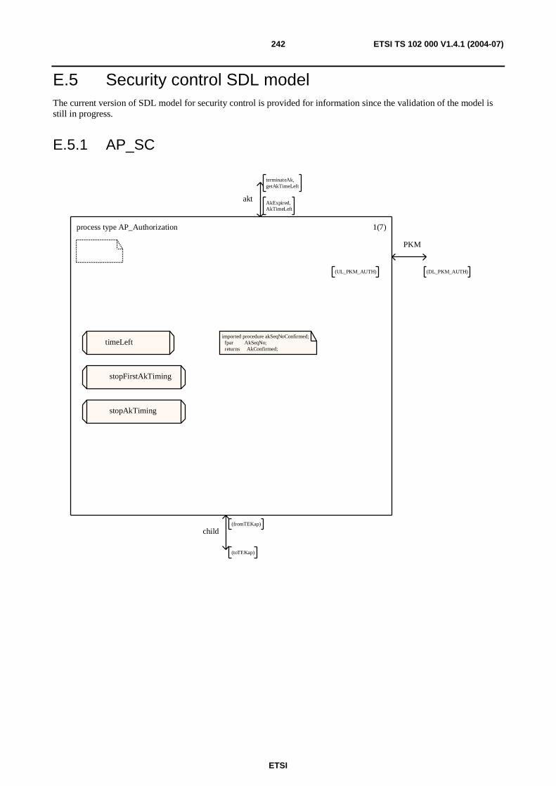
ETSI
ETSI TS 102 000 V1.4.1 (2004-07) 242
E.5 Security control SDL model The current version of SDL model for security control is provided for information since the validation of the model is still in progress.
E.5.1 AP_SC
process type AP_Authorization 1(7)
imported procedure akSeqNoConfirmed; fpar AkSeqNo; returns AkConfirmed;
timeLeft
stopFirstAkTiming
stopAkTiming
akt
terminateAk,getAkTimeLeft
AkExpired,AkTimeLeft
PKM
(DL_PKM_AUTH)(UL_PKM_AUTH)
child
(toTEKap)
(fromTEKap)

ETSI
ETSI TS 102 000 V1.4.1 (2004-07) 243
process type AP_Authorization 2(7)
DCL authManufacturerInfo RlcAuthManufacturerInfo;/* fields: manufacturerX509certificate */
DCL authReq RlcAuthReq;/* fields:AtX509certificate, AtPublicKey, ManufacturerId */
DCL authReply RlcAuthReply;/* fields:AuthKey, AkSeqNo, AkLifeTime, Said */
DCL authReject RlcAuthReject;/* fields:AuthErrorCode, ErrorInfoText[Optional]*/
DCL authInvalid RlcAuthInvalid;/* fields:authInvalidErrorCodeerrorInfoText OPTIONAL */
DCL tekReq RlcTekReq;/* fields: Said */
DCL akSeqNo AkSeqNo;DCL said Said;
DCL akRecord AkRecord;DCL akList AkList;DCL akTimeLeft Integer;
DCL isAkInvalid IsAkInvalid := maxAkInvalid;
TIMER T_AuthCmd := T_AuthCmdDuration;
TIMER T_AuthRequestRetry;
exported procedure SaidApInvalid; start; return;endprocedure;

ETSI
ETSI TS 102 000 V1.4.1 (2004-07) 244
process type AP_Authorization 3(7)
*
SaidApInvalid
stopAkTiming(akList)
Idle
ManInfoWait
RlcAuthReq(authReq)
In case ManInfois lost
ManInfoWait
RlcAuthManufa_cturerInfo(authManufa_cturerInfo)
AuthWait
T_AuthCmd
RlcAuthCmd
Exception
No ManInfo from theterminal
AP resends RlcAuthCmd
set(T_AuthCmd)
ManInfoWait
Idle
NONE
RlcAuthCmdPrivacy initialization begins with the AP sending the AT an authentication command (RlcAuthCmd) message.
akSeqNo :=any(AkSeqNo)
set(T_AuthCmd)
ManInfoWait
AuthRejectWait
*
Added so thatall signals receivedwhile in this stateare discarded
AuthRejectWait
T_Auth_RequestRetry
Waiting before anew authorisationmay be initiated
Idle
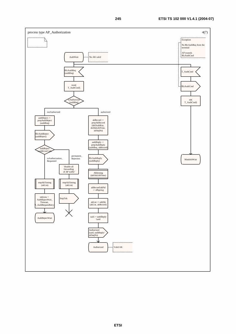
ETSI
ETSI TS 102 000 V1.4.1 (2004-07) 245
process type AP_Authorization 4(7)
AuthWait No AK valid
RlcAuthReq(authReq)
reset(T_AuthCmd)
isAuthorized(authReq)
authReject := prepAuthReject
(authReq)
RlcAuthReject(authReject)
authReject!authErrorCode
'disable all forwarding of AP traffic'
stopAkTiming(akList)
StopTek
stopAkTiming(akList)
set(now + AuthRejectWait_
Timeout, T_AuthRequestRetry)
AuthRejectWait
akRecord :=prepAkRecord(defAuthKey,
defAkLifeTime, akSeqNo)
authReply := prepAuthReply
(authReq, akRecord)
RlcAuthReply(authReply)
AKtiming(defAkLifeTime)
akRecord!akPid:= offspring
akList := addAk(akList, akRecord)
said := authReply!said
Authorized(said, authReply!akSeqNo)
Authorized Valid AK
T_AuthCmd
RlcAuthCmd
Exception
No RlcAuthReq from theterminal
AP resends RlcAuthCmd
set(T_AuthCmd)
ManInfoWait
notAuthorized
permanent_Rejection reAuthorization_
Requested
authorized
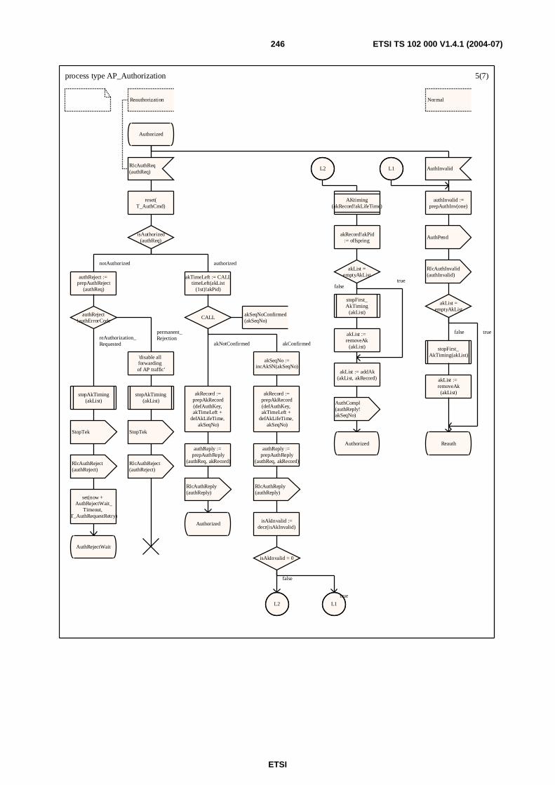
ETSI
ETSI TS 102 000 V1.4.1 (2004-07) 246
process type AP_Authorization 5(7)
Normal
Authorized
RlcAuthReq(authReq)
Reauthorization
reset(T_AuthCmd)
isAuthorized(authReq)
authReject := prepAuthReject
(authReq)
authReject!authErrorCode
'disable all forwarding of AP traffic'
stopAkTiming(akList)
StopTek
RlcAuthReject(authReject)
stopAkTiming(akList)
StopTek
RlcAuthReject(authReject)
set(now + AuthRejectWait_
Timeout, T_AuthRequestRetry)
AuthRejectWait
akTimeLeft := CALLtimeLeft(akList
(1st)!akPid)
CALL akSeqNoConfirmed(akSeqNo)
akSeqNo :=incAkSN(akSeqNo)
akRecord :=prepAkRecord(defAuthKey, akTimeLeft +
defAkLifeTime, akSeqNo)
authReply := prepAuthReply
(authReq, akRecord)
RlcAuthReply(authReply)
isAkInvalid :=decr(isAkInvalid)
isAkInvalid = 0
L2 L1
akRecord :=prepAkRecord(defAuthKey, akTimeLeft +
defAkLifeTime, akSeqNo)
authReply := prepAuthReply
(authReq, akRecord)
RlcAuthReply(authReply)
Authorized
AuthInvalid
authInvalid :=prepAuthInv(one)
AuthPend
RlcAuthInvalid(authInvalid)
akList =emptyAkList
stopFirst_AkTiming(akList)
akList := removeAk(akList)
Reauth
L2
AKtiming(akRecord!akLifeTime)
akRecord!akPid:= offspring
akList =emptyAkList
stopFirst_AkTiming
(akList)
akList := removeAk
(akList)
akList := addAk(akList, akRecord)
AuthCompl(authReply!akSeqNo)
Authorized
L1
notAuthorized
permanent_Rejection reAuthorization_
Requested
authorized
akConfirmed
false
true
akNotConfirmed
false true
falsetrue
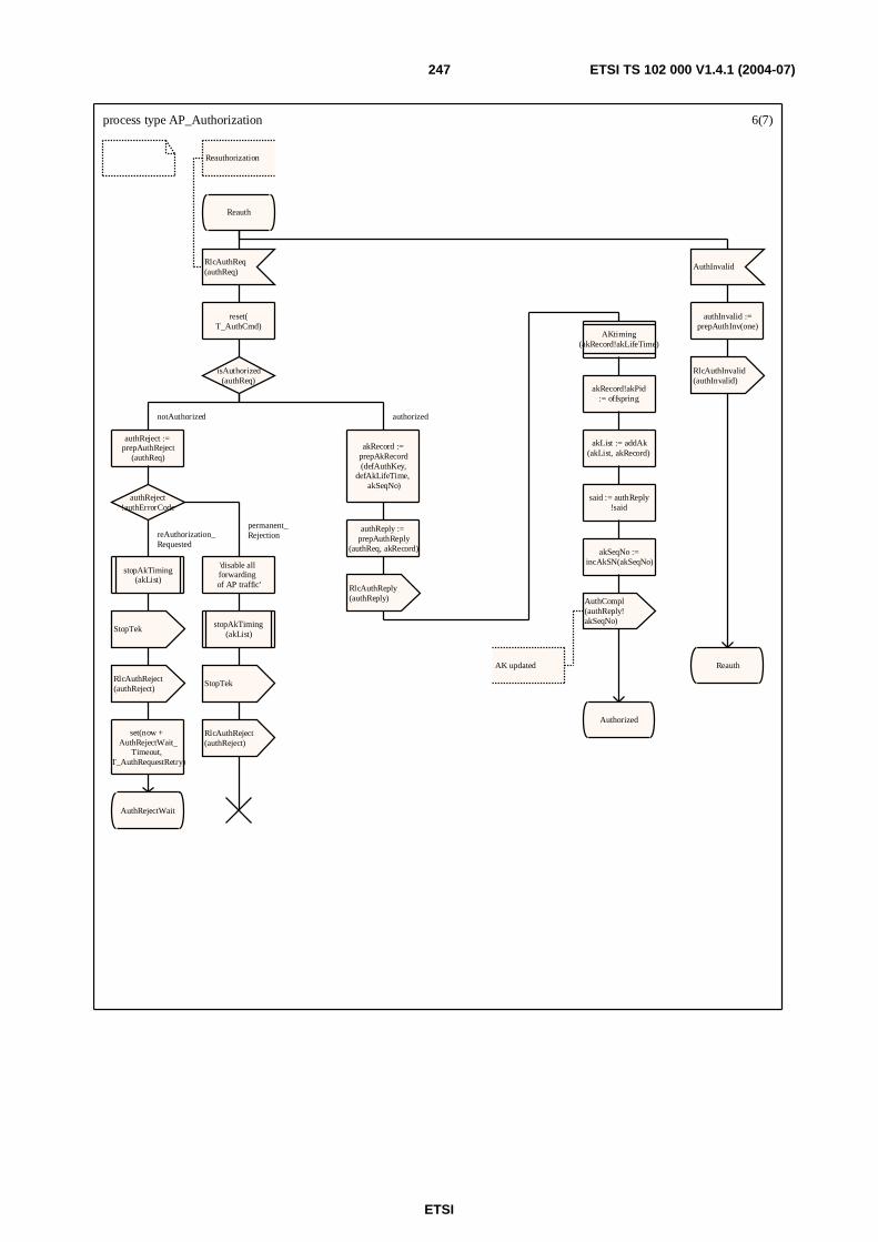
ETSI
ETSI TS 102 000 V1.4.1 (2004-07) 247
process type AP_Authorization 6(7)
Reauth
RlcAuthReq(authReq)
Reauthorization
reset(T_AuthCmd)
isAuthorized(authReq)
authReject := prepAuthReject
(authReq)
authReject!authErrorCode
stopAkTiming(akList)
StopTek
RlcAuthReject(authReject)
set(now + AuthRejectWait_
Timeout, T_AuthRequestRetry)
AuthRejectWait
'disable all forwarding of AP traffic'
stopAkTiming(akList)
StopTek
RlcAuthReject(authReject)
akRecord :=prepAkRecord(defAuthKey,
defAkLifeTime, akSeqNo)
authReply := prepAuthReply
(authReq, akRecord)
RlcAuthReply(authReply)
AKtiming(akRecord!akLifeTime)
akRecord!akPid:= offspring
akList := addAk(akList, akRecord)
said := authReply!said
akSeqNo :=incAkSN(akSeqNo)
AuthCompl(authReply!akSeqNo)
AK updated
Authorized
AuthInvalid
authInvalid :=prepAuthInv(one)
RlcAuthInvalid(authInvalid)
Reauth
notAuthorized
reAuthorization_Requested
permanent_Rejection
authorized
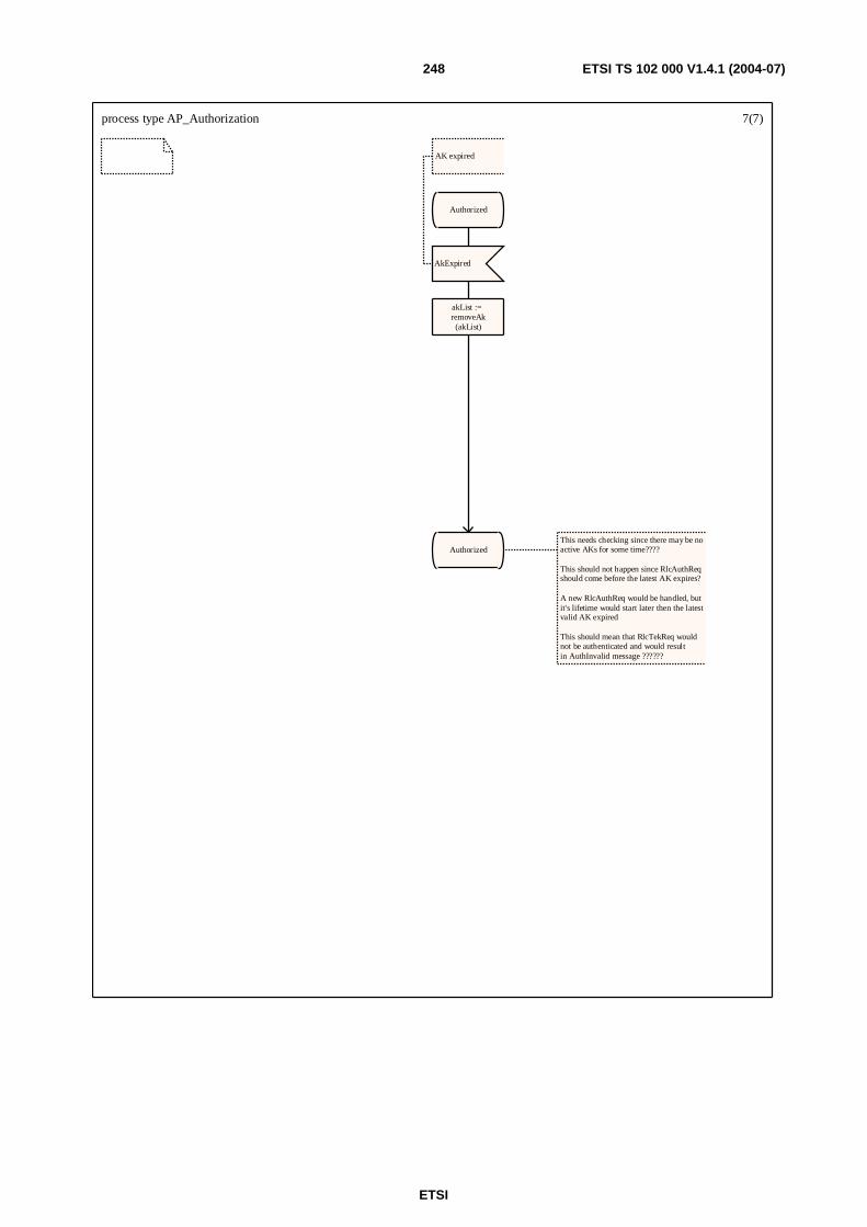
ETSI
ETSI TS 102 000 V1.4.1 (2004-07) 248
process type AP_Authorization 7(7)
Authorized
AkExpired
AK expired
akList := removeAk(akList)
AuthorizedThis needs checking since there may be noactive AKs for some time????
This should not happen since RlcAuthReqshould come before the latest AK expires?
A new RlcAuthReq would be handled, butit's lifetime would start later then the latestvalid AK expired
This should mean that RlcTekReq wouldnot be authenticated and would resultin AuthInvalid message ??????
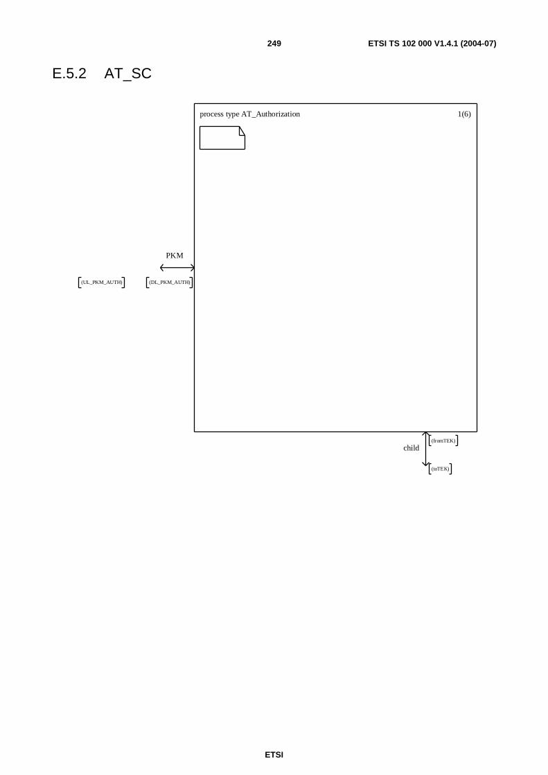
ETSI
ETSI TS 102 000 V1.4.1 (2004-07) 249
E.5.2 AT_SC
process type AT_Authorization 1(6)
PKM
(UL_PKM_AUTH) (DL_PKM_AUTH)
child
(toTEK)
(fromTEK)

ETSI
ETSI TS 102 000 V1.4.1 (2004-07) 250
process type AT_Authorization 2(6)
TIMER T_AuthReq := T_AuthReqDuration;TIMER T_AuthRequestRetry;
DCL authManufacturerInfo RlcAuthManufacturerInfo;/* fields: manufacturerX509certificate */
DCL authReq RlcAuthReq;/* fields:AtX509certificate, AtPublicKey, ManufacturerId */
DCL authReply RlcAuthReply;/* fields:AuthKey, AkSeqNo, AkLifeTime, Said */
DCL authReject RlcAuthReject;/* fields:AuthErrorCode, ErrorInfoText[Optional]*/
DCL authInvalid RlcAuthInvalid;/* fields:authInvalidErrorCodeerrorInfoText OPTIONAL */
DCL said Said;
DCL currentAkSeqNo AkSeqNo;
DCL akList AkList;DCL akRecord AkRecord;
exported procedure SaidInvalid; start; return;endprocedure;
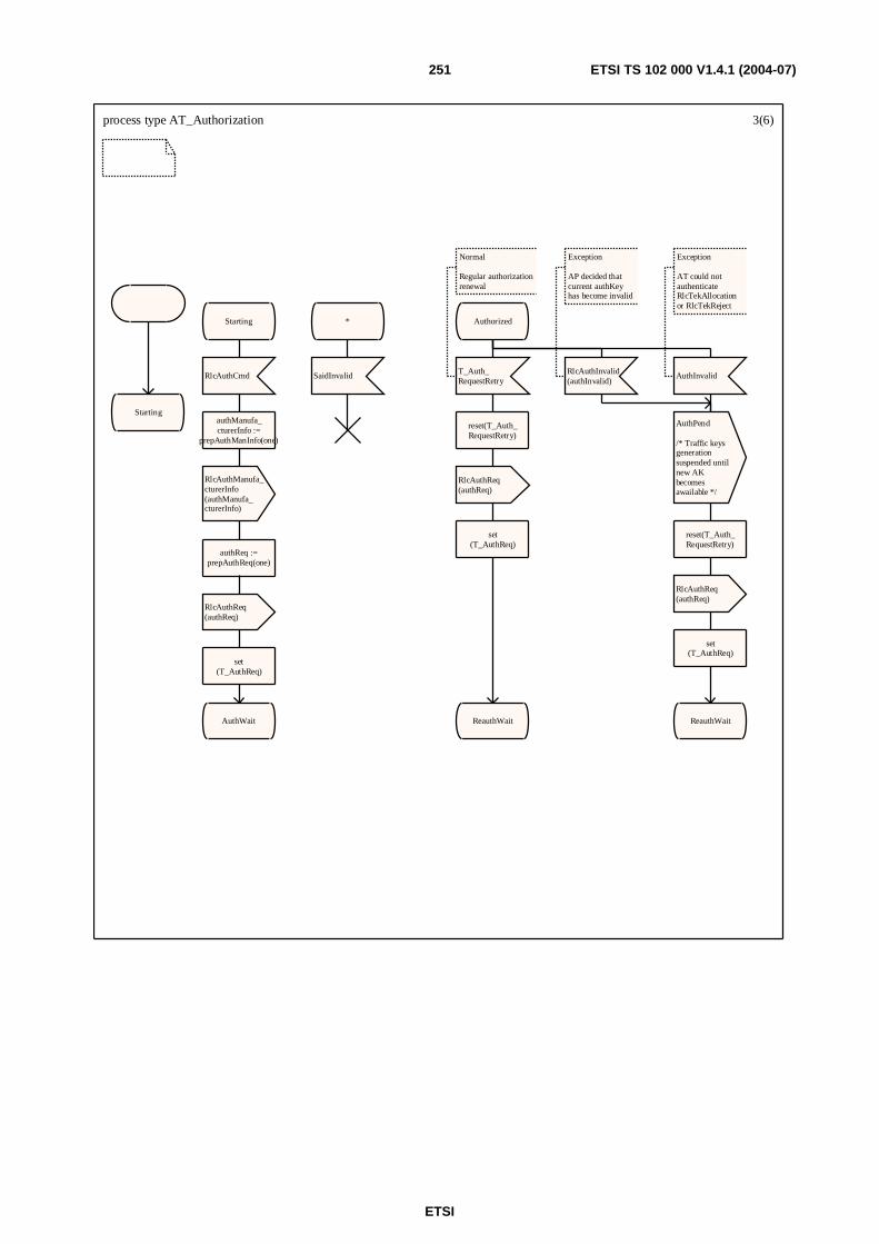
ETSI
ETSI TS 102 000 V1.4.1 (2004-07) 251
process type AT_Authorization 3(6)
Starting
Starting
RlcAuthCmd
authManufa_cturerInfo :=
prepAuthManInfo(one)
RlcAuthManufa_cturerInfo(authManufa_cturerInfo)
authReq :=prepAuthReq(one)
RlcAuthReq(authReq)
set(T_AuthReq)
AuthWait
*
SaidInvalid
Authorized
T_Auth_RequestRetry
Normal
Regular authorizationrenewal
reset(T_Auth_RequestRetry)
RlcAuthReq(authReq)
set(T_AuthReq)
ReauthWait
RlcAuthInvalid(authInvalid)
Exception
AP decided thatcurrent authKeyhas become invalid
AuthPend
/* Traffic keys generation suspended until new AKbecomes awailable */
reset(T_Auth_RequestRetry)
RlcAuthReq(authReq)
set(T_AuthReq)
ReauthWait
AuthInvalid
Exception
AT could not authenticateRlcTekAllocationor RlcTekReject
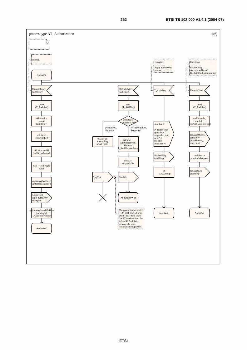
ETSI
ETSI TS 102 000 V1.4.1 (2004-07) 252
process type AT_Authorization 4(6)
AuthWait
RlcAuthReply(authReply)
Normal
reset(T_AuthReq)
akRecord :=saveAk
(authReply)
akList :=emptyAkList
akList := addAk(akList, akRecord)
said := authReply!said
currentAkSeqNo :=authReply!akSeqNo
Authorized(said, authReply!akSeqNo)
set(now+calcAkLifeTime(authReply),
T_AuthRequestRetry)
Authorized
RlcAuthReject(authReject)
reset(T_AuthReq)
authReject!authErrorCode
'disable all forwarding
of AT traffic'
StopTek
The parent Authorization FSM shall stop all of its child TEK FSMs when the AT receives from the AP an RlcAuthReject message during a reauthorization process.
set(now + AuthRejectWait_
Timeout, T_AuthRequestRetry)
akList := emptyAkList
StopTek
AuthRejectWait
T_AuthReq
Exception
Reply not receivedin time
AuthPend
/* Traffic keys generation suspended until new AKbecomes awailable */
RlcAuthReq(authReq)
set(T_AuthReq)
AuthWait
RlcAuthCmd
Exception
RlcAuthReqnot received by APRlcAuthCmd retransmitted
reset(T_AuthReq)
authManufa_cturerInfo :=
prepAuthManInfo(one)
RlcAuthManufa_cturerInfo(authManufa_cturerInfo)
authReq :=prepAuthReq(one)
RlcAuthReq(authReq)
AuthWait
permanent_Rejection
reAuthorization_Requested
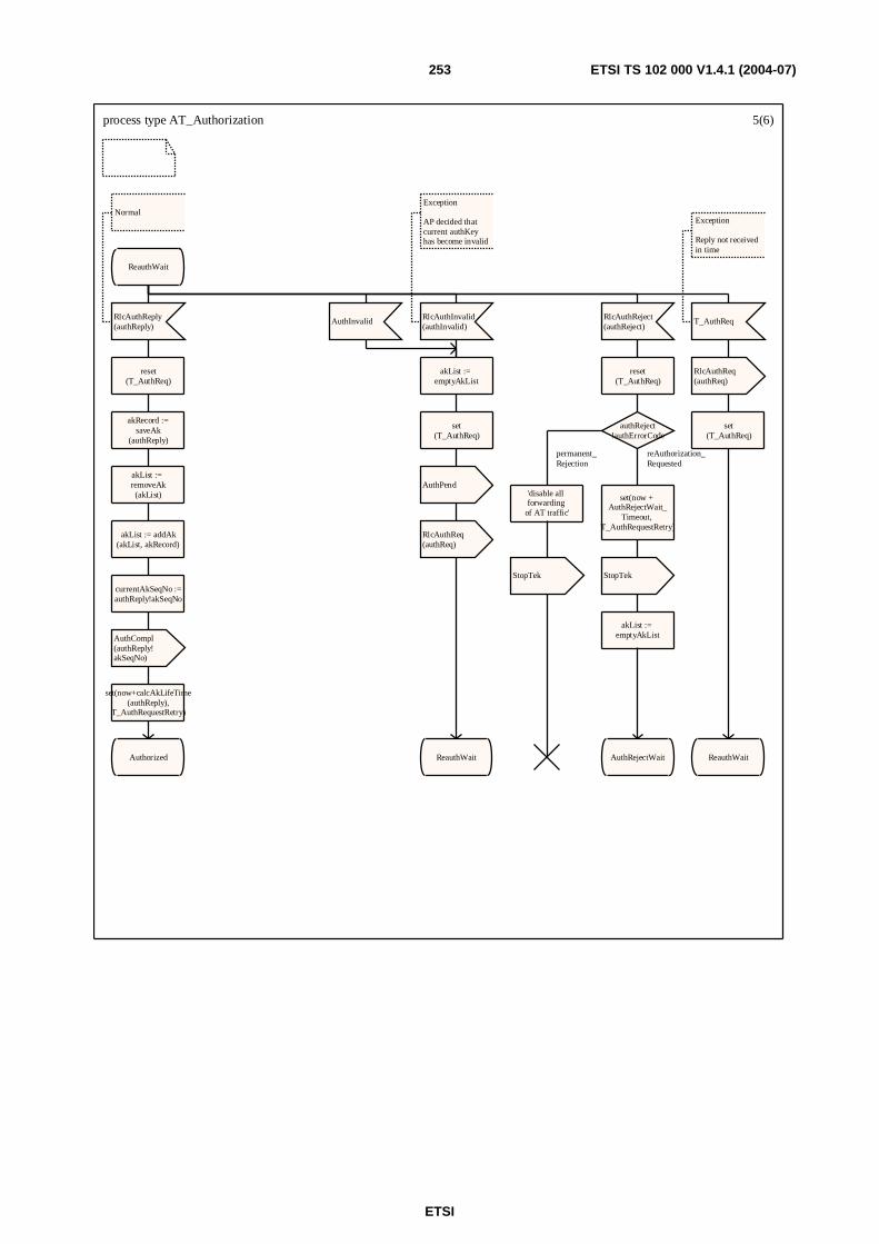
ETSI
ETSI TS 102 000 V1.4.1 (2004-07) 253
process type AT_Authorization 5(6)
ReauthWait
RlcAuthReply(authReply)
Normal
reset(T_AuthReq)
akRecord :=saveAk
(authReply)
akList := removeAk(akList)
akList := addAk(akList, akRecord)
currentAkSeqNo :=authReply!akSeqNo
AuthCompl(authReply!akSeqNo)
set(now+calcAkLifeTime(authReply),
T_AuthRequestRetry)
Authorized
AuthInvalid
akList := emptyAkList
set(T_AuthReq)
AuthPend
RlcAuthReq(authReq)
ReauthWait
RlcAuthInvalid(authInvalid)
Exception
AP decided thatcurrent authKeyhas become invalid
RlcAuthReject(authReject)
reset(T_AuthReq)
authReject!authErrorCode
'disable all forwarding
of AT traffic'
StopTek
set(now + AuthRejectWait_
Timeout, T_AuthRequestRetry)
StopTek
akList := emptyAkList
AuthRejectWait
T_AuthReq
Exception
Reply not receivedin time
RlcAuthReq(authReq)
set(T_AuthReq)
ReauthWait
permanent_Rejection
reAuthorization_Requested
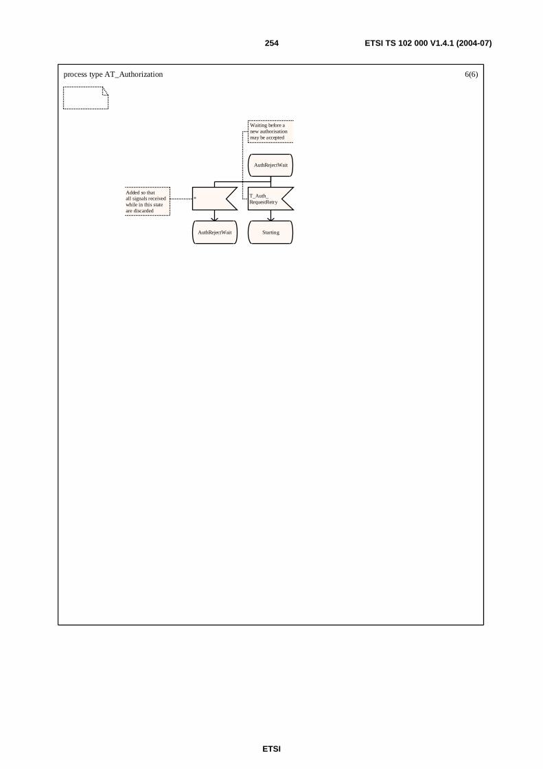
ETSI
ETSI TS 102 000 V1.4.1 (2004-07) 254
process type AT_Authorization 6(6)
AuthRejectWait
*Added so thatall signals receivedwhile in this stateare discarded
AuthRejectWait
T_Auth_RequestRetry
Waiting before anew authorisationmay be accepted
Starting
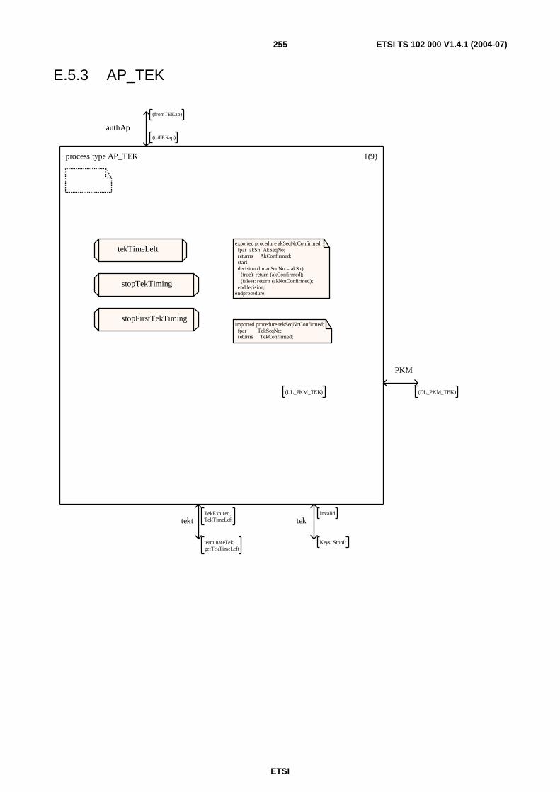
ETSI
ETSI TS 102 000 V1.4.1 (2004-07) 255
E.5.3 AP_TEK
process type AP_TEK 1(9)
exported procedure akSeqNoConfirmed; fpar akSn AkSeqNo; returns AkConfirmed; start; decision (hmacSeqNo = akSn); (true): return (akConfirmed); (false): return (akNotConfirmed); enddecision;endprocedure;
imported procedure tekSeqNoConfirmed; fpar TekSeqNo; returns TekConfirmed;
tekTimeLeft
stopTekTiming
stopFirstTekTiming
authAp
(fromTEKap)
(toTEKap)
PKM
(DL_PKM_TEK)(UL_PKM_TEK)
tekt
terminateTek,getTekTimeLeft
TekExpired,TekTimeLeft tek
Keys, StopIt
Invalid
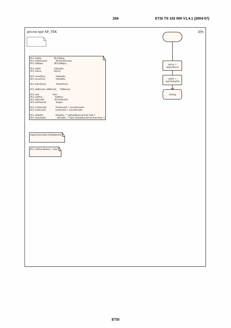
ETSI
ETSI TS 102 000 V1.4.1 (2004-07) 256
process type AP_TEK 2(9)
DCL tekReq RlcTekReq;DCL tekAllocation RlcTekAllocation;DCL tekReject RlcTekReject;
DCL tekSN TekSeqNo;DCL tekList TekList;
DCL activeDLsn TekSeqNo;DCL activeULsn TekSeqNo;
DCL tekLifeTime TekLifeTime;
DCL tekRecord1, tekRecord2 TekRecord;
DCL said Said;DCL authKey AuthKey;DCL tekInvalid RlcTekInvalid;DCL tekTimeLeft Integer;
DCL isTekInvalid IsTekInvalid := maxTekInvalid;DCL isAkInvalid IsAkInvalid := maxAkInvalid;
DCL akSeqNo AkSeqNo; /* seqNumReceived from Auth */DCL hmacSeqNo AkSeqNo; /* latest AkSeqNum derived from hmac */
imported procedure SaidApInvalid;
DCL testData Boolean := false;
tekList :=emptyTekList
tekSN :=any(TekSeqNo)
Starting
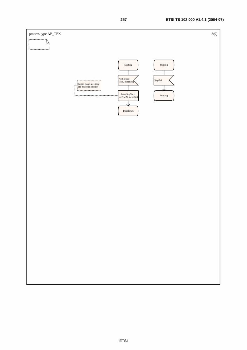
ETSI
ETSI TS 102 000 V1.4.1 (2004-07) 257
process type AP_TEK 3(9)
Starting
Authorized(said, akSeqNo)
hmacSeqNo :=incAkSN(akSeqNo)
Just to make sure they are not equal initialy
InitialTEK
Starting
StopTek
Starting
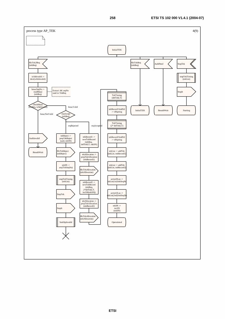
ETSI
ETSI TS 102 000 V1.4.1 (2004-07) 258
process type AP_TEK 4(9)
InitialTEK
RlcTek2Req(tekReq)
isAkInvalid :=decr(isAkInvalid)
hmacSeqNo :=readHmac(tekReq)
Extract AK seqNo used in TekReq
checkHmac(tekReq, isAkInvalid)
reqAccept(tekReq)
tekReject :=prepTekReject(said, tekSN)
RlcTekReject(tekReject)
tekSN :=any(TekSeqNo)
stopTekTiming(tekList)
StopTek
StopIt
SaidApInvalid
tekRecord1 :=newTekRecord
(tekReq, defTekLT, tekSN)
tekAllocation :=prepTekAllocation
(tekRecord1)
RlcTekAllocation(tekAllocation)
tekRecord2 :=newTekRecord
(tekReq, 2*defTekLT, incSN(tekSN))
tekAllocation :=prepTekAllocation
(tekRecord2)
RlcTekAllocation(tekAllocation)
TekTiming(defTekLT)
tekRecord1!tekPid:= offspring
TekTiming(2* defTekLT)
tekRecord2!tekPid:= offspring
tekList := addTek(tekList, tekRecord1)
tekList := addTek(tekList, tekRecord2)
activeDLsn :=tekList(1st)!tekSeqNo
activeULsn :=tekList(2nd)!tekSeqNo
tekSN :=incSN
(tekSN)
Operational
AuthInvalid
ReauthWait
RlcTekReq(tekReq)
InitialTEK
AuthPend
ReauthWait
StopTek
stopTekTiming(tekList)
StopIt
Starting
hmacValid
reqRejected reqAccepted
hmacNotValid
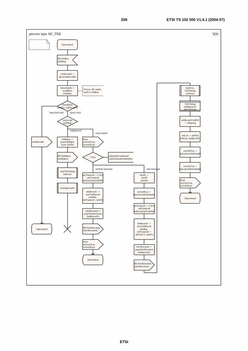
ETSI
ETSI TS 102 000 V1.4.1 (2004-07) 259
process type AP_TEK 5(9)
Operational
RlcTekReq(tekReq)
isAkInvalid :=decr(isAkInvalid)
hmacSeqNo :=readHmac(tekReq)
Extract AK seqNo used in TekReq
checkHmac(tekReq, isAkInvalid)
reqAccept(tekReq)
tekReject :=prepTekReject(said, tekSN)
RlcTekReject(tekReject)
stopTekTiming(tekList)
SaidApInvalid
Keys(activeULsn,activeDLsn)
CALL tekSeqNoConfirmed(tekList(2nd)!tekSeqNo)
tekTimeLeft := CALLtekTimeLeft
(tekList(2nd)!tekPid)
tekRecord1 :=newTekRecord
(tekReq, tekTimeLeft , tekSN)
tekAllocation :=prepTekAllocation
(tekRecord1)
RlcTekAllocation(tekAllocation)
Keys(activeULsn,activeDLsn)
Operational
tekSN :=incSN
(tekSN)
activeDLsn :=tekList(2nd)!tekSeqNo
tekTimeLeft := CALLtekTimeLeft
(tekList(2nd)!tekPid)
tekRecord1 :=newTekRecord
(tekReq, tekTimeLeft +
defTekLT, tekSN)
tekAllocation :=prepTekAllocation
(tekRecord1)
RlcTekAllocation(tekAllocation)
stopFirst_TekTiming
(tekList)
TekTiming(tekRecord1!tekLifeTime)
tekRecord1!tekPid:= offspring
tekList := addTek(tekList, tekRecord1)
activeDLsn :=tekList(1st)!tekSeqNo
activeULsn :=tekList(2nd)!tekSeqNo
Keys(activeULsn,activeDLsn)
Operational
AuthInvalid
Operational
hmacValid
reqRejectedreqAccepted
tekNotConfirmed tekConfirmed
hmacNotValid
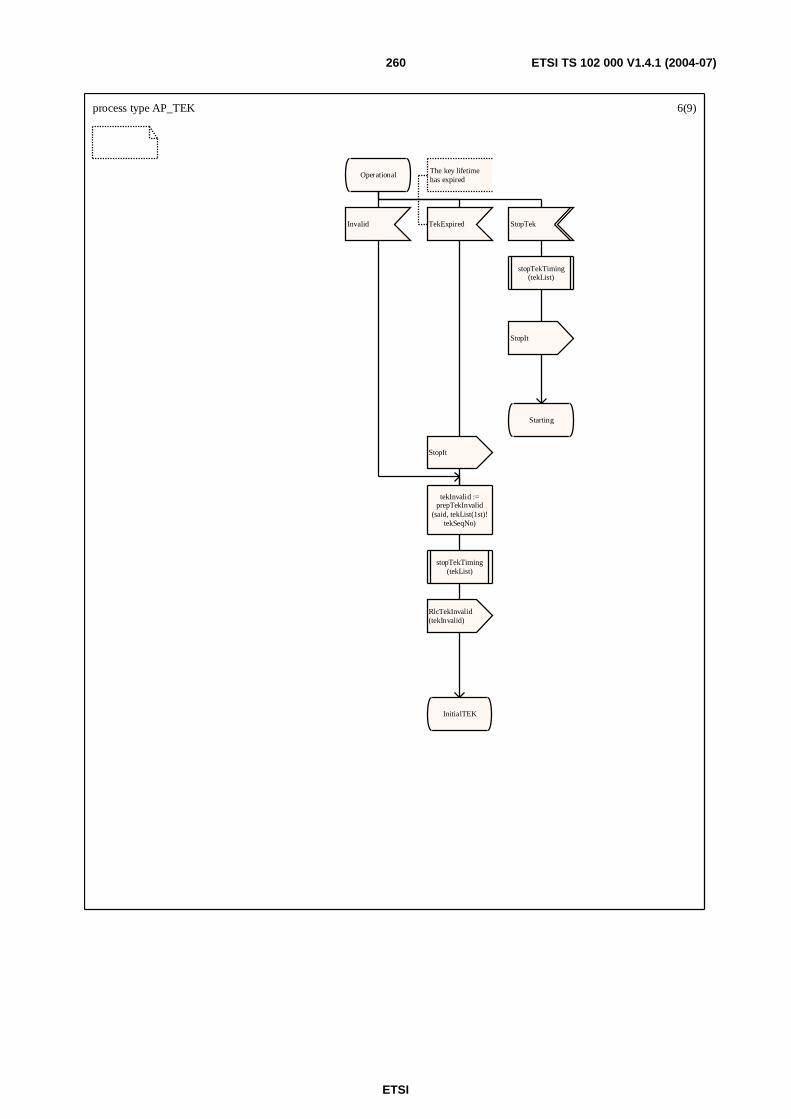
ETSI
ETSI TS 102 000 V1.4.1 (2004-07) 260
process type AP_TEK 6(9)
Operational
Invalid
tekInvalid :=prepTekInvalid
(said, tekList(1st)!tekSeqNo)
stopTekTiming(tekList)
RlcTekInvalid(tekInvalid)
InitialTEK
TekExpired
The key lifetimehas expired
StopIt
StopTek
stopTekTiming(tekList)
StopIt
Starting
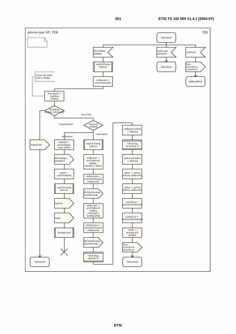
ETSI
ETSI TS 102 000 V1.4.1 (2004-07) 261
process type AP_TEK 7(9)
Operational
RlcTek2Req(tekReq)
stopTekTiming(tekList)
isAkInvalid :=decr(isAkInvalid)
hmacSeqNo :=readHmac(tekReq)
Extract AK seqNo used in TekReq
checkHmac(tekReq, isAkInvalid)
reqAccept(tekReq)
tekReject :=prepTekReject(said, tekSN)
RlcTekReject(tekReject)
tekSN :=any(TekSeqNo)
stopTekTiming(tekList)
StopTek
StopIt
SaidApInvalid
stopTekTiming(tekList)
tekRecord1 :=newTekRecord
(tekReq, defTekLT, tekSN)
tekAllocation :=prepTekAllocation
(tekRecord1)
RlcTekAllocation(tekAllocation)
tekRecord2 :=newTekRecord
(tekReq, 2*defTekLT, incSN(tekSN))
tekAllocation :=prepTekAllocation
(tekRecord2)
RlcTekAllocation(tekAllocation)
TekTiming(defTekLT)
tekRecord1!tekPid:= offspring
TekTiming(2* defTekLT)
tekRecord2!tekPid:= offspring
tekList := addTek(tekList, tekRecord1)
tekList := addTek(tekList, tekRecord2)
activeDLsn :=tekList(1st)!tekSeqNo
activeULsn :=tekList(2nd)!tekSeqNo
tekSN :=incSN(incSN
(tekSN))
Keys(activeULsn,activeDLsn)
Operational
AuthInvalid
Operational
AuthCompl(akSeqNo)
Operational
AuthPend
Keys(activeULsn,activeDLsn)
OpReauthWait
hmacValid
reqRejectedreqAccepted
hmacNotValid

ETSI
ETSI TS 102 000 V1.4.1 (2004-07) 262
process type AP_TEK 8(9)
ReauthWait
AuthCompl(akSeqNo)
InitialTEK
StopTek
stopTekTiming(tekList)
StopIt
Starting
TekExpired
The key lifetimehas expired
stopTekTiming(tekList)
StopIt
ReauthWait
RlcTekReq(tekReq)
AuthInvalid
ReauthWait
RlcTek2Req(tekReq)
AuthInvalid
ReauthWait
AuthPend
ReauthWait
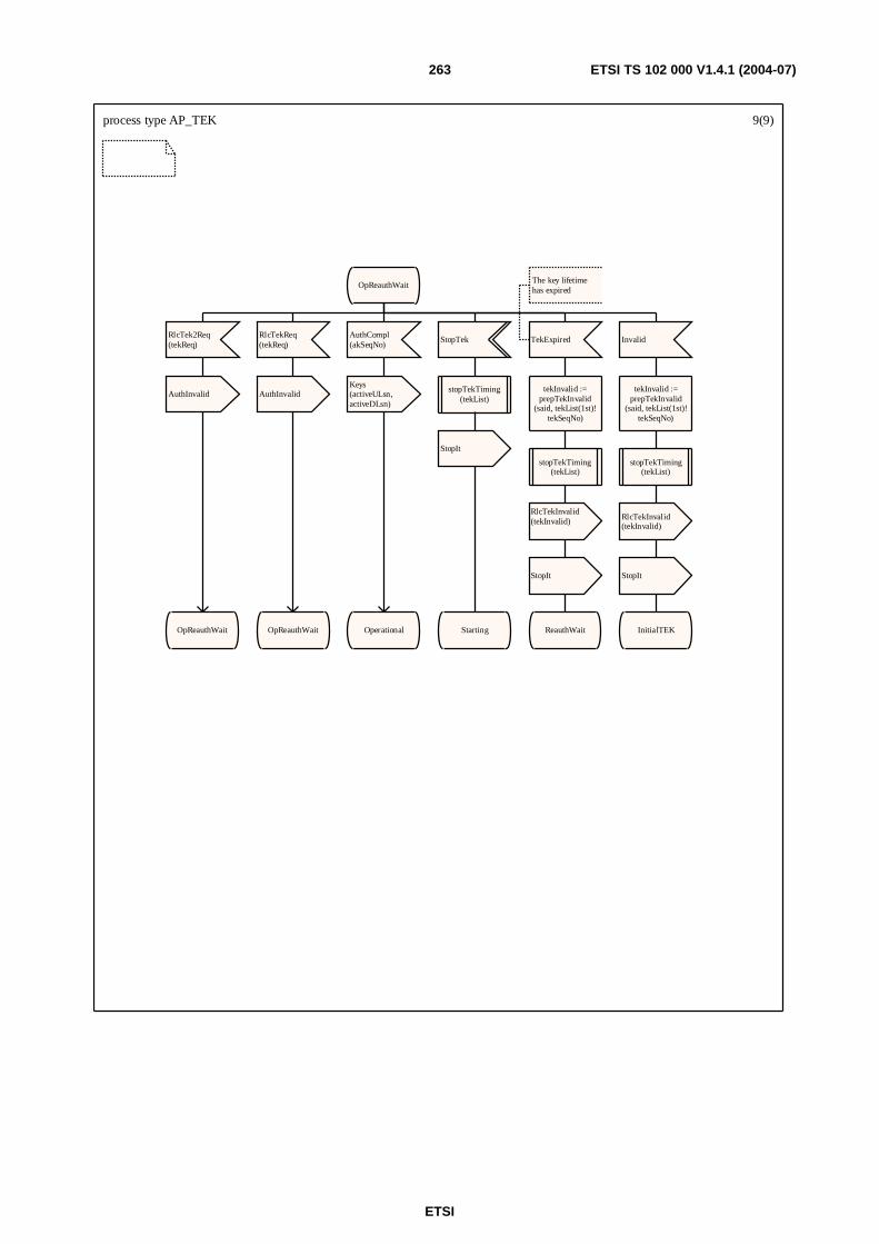
ETSI
ETSI TS 102 000 V1.4.1 (2004-07) 263
process type AP_TEK 9(9)
OpReauthWait
RlcTek2Req(tekReq)
AuthInvalid
OpReauthWait
RlcTekReq(tekReq)
AuthInvalid
OpReauthWait
AuthCompl(akSeqNo)
Keys(activeULsn,activeDLsn)
Operational
StopTek
stopTekTiming(tekList)
StopIt
Starting
TekExpired
The key lifetimehas expired
tekInvalid :=prepTekInvalid
(said, tekList(1st)!tekSeqNo)
stopTekTiming(tekList)
RlcTekInvalid(tekInvalid)
StopIt
ReauthWait
Invalid
tekInvalid :=prepTekInvalid
(said, tekList(1st)!tekSeqNo)
stopTekTiming(tekList)
RlcTekInvalid(tekInvalid)
StopIt
InitialTEK
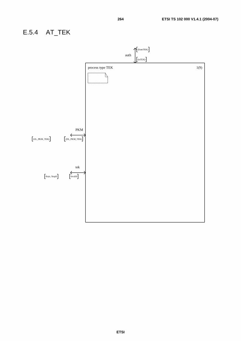
ETSI
ETSI TS 102 000 V1.4.1 (2004-07) 264
E.5.4 AT_TEK
process type TEK 1(9)
auth
(fromTEK)
(toTEK)
PKM
(UL_PKM_TEK) (DL_PKM_TEK)
tek
Keys, StopIt Invalid
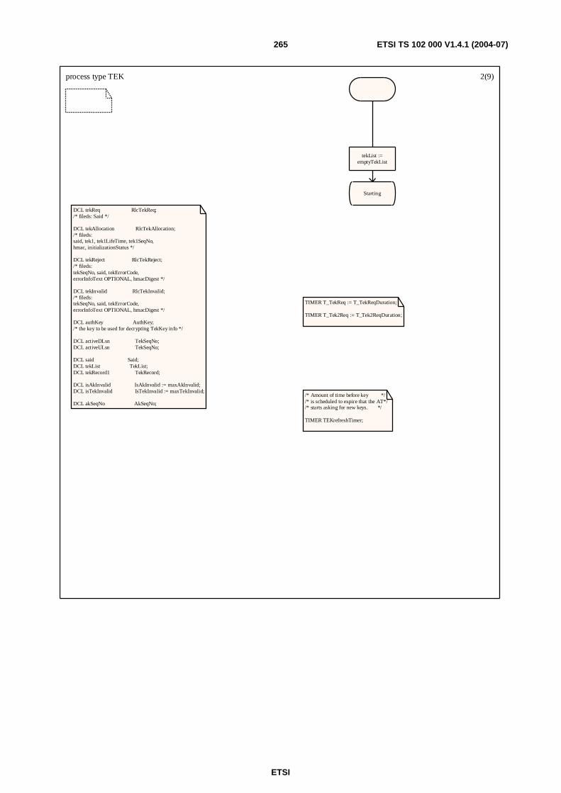
ETSI
ETSI TS 102 000 V1.4.1 (2004-07) 265
process type TEK 2(9)
DCL tekReq RlcTekReq;/* fileds: Said */
DCL tekAllocation RlcTekAllocation;/* fileds:said, tek1, tek1LifeTime, tek1SeqNo, hmac, initializationStatus */
DCL tekReject RlcTekReject;/* fileds:tekSeqNo, said, tekErrorCode,errorInfoText OPTIONAL, hmacDigest */
DCL tekInvalid RlcTekInvalid;/* fileds:tekSeqNo, said, tekErrorCode,errorInfoText OPTIONAL, hmacDigest */
DCL authKey AuthKey;/* the key to be used for decrypting TekKey info */
DCL activeDLsn TekSeqNo;DCL activeULsn TekSeqNo;
DCL said Said;DCL tekList TekList; DCL tekRecord1 TekRecord;
DCL isAkInvalid IsAkInvalid := maxAkInvalid;DCL isTekInvalid IsTekInvalid := maxTekInvalid;
DCL akSeqNo AkSeqNo;
TIMER T_TekReq := T_TekReqDuration;
TIMER T_Tek2Req := T_Tek2ReqDuration;
/* Amount of time before key *//* is scheduled to expire that the AT*//* starts asking for new keys. */
TIMER TEKrefreshTimer;
tekList :=emptyTekList
Starting
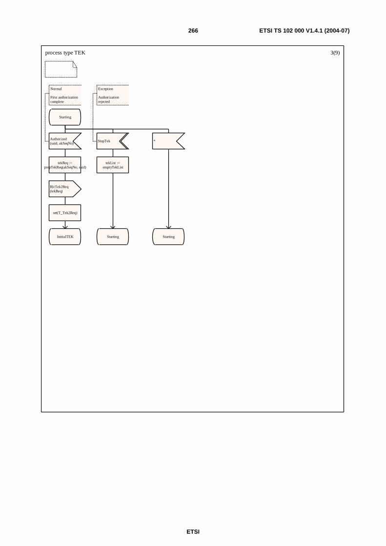
ETSI
ETSI TS 102 000 V1.4.1 (2004-07) 266
process type TEK 3(9)
Starting
Authorized(said, akSeqNo)
Normal
First authorizationcomplete
tekReq :=prepTekReq(akSeqNo, said)
RlcTek2Req(tekReq)
set(T_Tek2Req)
InitialTEK
StopTek
Exception
Authorizationrejected
tekList :=emptyTekList
Starting
*
Starting

ETSI
ETSI TS 102 000 V1.4.1 (2004-07) 267
process type TEK 4(9)
InitialTEK
RlcTekAllocation(tekAllocation)
Normal
First allocation
isAkInvalid :=decr(isAkInvalid)
checkHmac(tekAllocation,
isAkInvalid)
tekRecord1 :=saveTekRecord(tekAllocation)
tekList := addTek(tekList, tekRecord1)
OpWait
reset(T_Tek2Req)
AuthInvalid
InitialTEK
RlcTekInvalid(tekInvalid)
Needs to be ignoredsince new key exchangeis in progress
InitialTEK
AuthPend
Exception
reset(T_Tek2Req)
OpReauthWait
T_Tek2Req
Exeception
FirstRlcTekAllocationnot arrived in time
tekReq :=prepTekReq(akSeqNo, said)
RlcTek2Req(tekReq)
set(T_Tek2Req)
InitialTEK
StopTek
reset(T_Tek2Req)
tekList :=emptyTekList
Starting
RlcTekReject(tekReject)
Exception
Rejected
SaidInvalid
hmacValid hmacNotValid
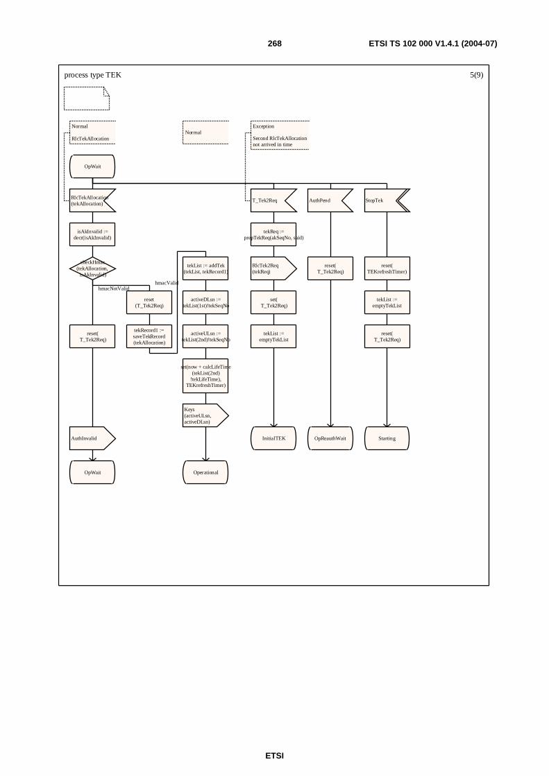
ETSI
ETSI TS 102 000 V1.4.1 (2004-07) 268
process type TEK 5(9)
Normal
OpWait
RlcTekAllocation(tekAllocation)
Normal
RlcTekAllocation
isAkInvalid :=decr(isAkInvalid)
checkHmac(tekAllocation,
isAkInvalid)
reset(T_Tek2Req)
tekRecord1 :=saveTekRecord(tekAllocation)
tekList := addTek(tekList, tekRecord1)
activeDLsn :=tekList(1st)!tekSeqNo
activeULsn :=tekList(2nd)!tekSeqNo
set(now + calcLifeTime(tekList(2nd)
!tekLifeTime),TEKrefreshTimer)
Keys(activeULsn,activeDLsn)
Operational
reset(T_Tek2Req)
AuthInvalid
OpWait
T_Tek2Req
Exception
Second RlcTekAllocationnot arrived in time
tekReq :=prepTekReq(akSeqNo, said)
RlcTek2Req(tekReq)
set(T_Tek2Req)
tekList :=emptyTekList
InitialTEK
AuthPend
reset(T_Tek2Req)
OpReauthWait
StopTek
reset(TEKrefreshTimer)
tekList :=emptyTekList
reset(T_Tek2Req)
Starting
hmacValidhmacNotValid
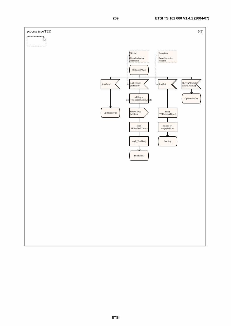
ETSI
ETSI TS 102 000 V1.4.1 (2004-07) 269
process type TEK 6(9)
OpReauthWait
AuthPend
OpReauthWait
AuthCompl(akSeqNo)
Normal
Reauthorizationcompleted
tekReq :=prepTekReq(akSeqNo, said)
RlcTek2Req(tekReq)
reset(TEKrefreshTimer)
set(T_Tek2Req)
InitialTEK
StopTek
Exception
Reauthorizationrejected
reset(TEKrefreshTimer)
tekList :=emptyTekList
Starting
RlcTekAllocation(tekAllocation)
OpReauthWait

ETSI
ETSI TS 102 000 V1.4.1 (2004-07) 270
process type TEK 7(9)
Operational
TEKrefreshTimer
Normal
Time to refresh the key
tekReq :=prepTekReq(akSeqNo, said)
RlcTekReq(tekReq)
Keys(activeULsn,activeDLsn)
set( T_TekReq)
RekeyWait
AuthPend
Operational
Invalid
StopIt
reset(TEKrefreshTimer)
tekList :=emptyTekList
tekReq :=prepTekReq(akSeqNo, said)
RlcTek2Req(tekReq)
set(T_Tek2Req)
InitialTEK
RlcTekInvalid(tekInvalid)
Exception
This is received from AP=>seqNum of trafic encryption keyused in uplink was wrong
StopTek
tekList :=emptyTekList
reset(TEKrefreshTimer)
StopIt
Starting

ETSI
ETSI TS 102 000 V1.4.1 (2004-07) 271
process type TEK 8(9)
RekeyWait
RlcTekAllocation(tekAllocation)
Normal
RlcTekAllocation
isAkInvalid :=decr(isAkInvalid)
checkHmac(tekAllocation,
isAkInvalid)
reset(T_TekReq)
AuthInvalid
RekeyWait
Keys(activeULsn,activeDLsn)
reset(T_TekReq)
tekRecord1 :=saveTekRecord(tekAllocation)
tekList := addTek(tekList, tekRecord1)
activeDLsn :=tekList(1st)!tekSeqNo
activeULsn :=tekList(2nd)!tekSeqNo
set(now + calcLifeTime(tekList(2nd)
!tekLifeTime),TEKrefreshTimer)
Keys(activeULsn,activeDLsn)
Operational
T_TekReq
tekReq :=prepTekReq(akSeqNo, said)
RlcTekReq(tekReq)
set(T_TekReq)
RekeyWait
StopTek
tekList :=emptyTekList
reset(T_TekReq)
StopIt
Starting
AuthPend
reset(T_TekReq)
Keys(activeULsn,activeDLsn)
RekeyReauthWait
Invalid
tekList :=emptyTekList
tekReq :=prepTekReq(akSeqNo, said)
RlcTek2Req(tekReq)
StopIt
set(T_Tek2Req)
reset(T_TekReq)
InitialTEK
RlcTekInvalid(tekInvalid)
RekeyWait
RlcTekReject(tekReject)
Exception
TekReq rejected
SaidInvalid
RekeyWait
AuthCompl(akSeqNo)
Use the new AK
RekeyWait
hmacNotValidhmacValid
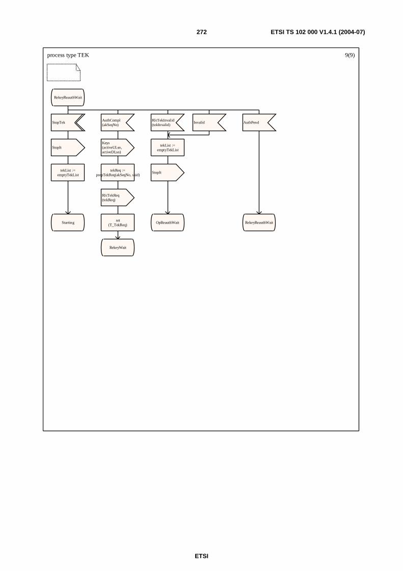
ETSI
ETSI TS 102 000 V1.4.1 (2004-07) 272
process type TEK 9(9)
RekeyReauthWait
StopTek
StopIt
tekList :=emptyTekList
Starting
AuthCompl(akSeqNo)
Keys(activeULsn,activeDLsn)
tekReq :=prepTekReq(akSeqNo, said)
RlcTekReq(tekReq)
set(T_TekReq)
RekeyWait
RlcTekInvalid(tekInvalid)
tekList :=emptyTekList
StopIt
OpReauthWait
Invalid AuthPend
RekeyReauthWait
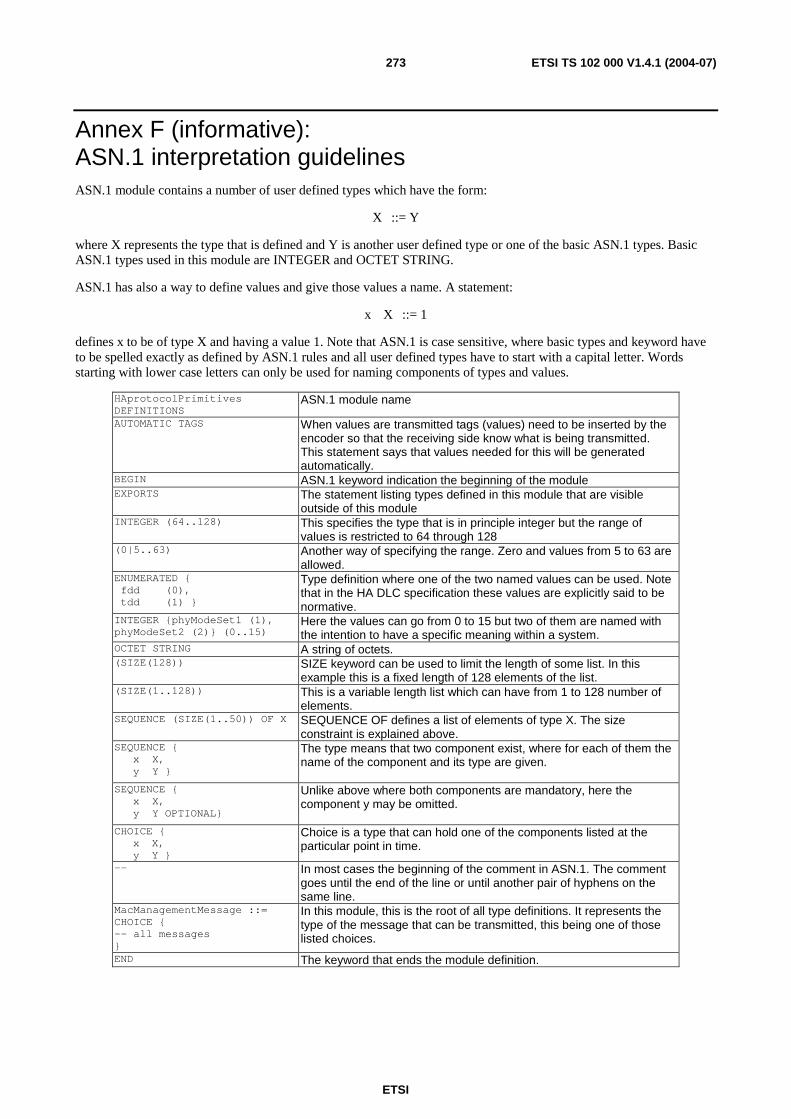
ETSI
ETSI TS 102 000 V1.4.1 (2004-07) 273
Annex F (informative): ASN.1 interpretation guidelines ASN.1 module contains a number of user defined types which have the form:
X ::= Y
where X represents the type that is defined and Y is another user defined type or one of the basic ASN.1 types. Basic ASN.1 types used in this module are INTEGER and OCTET STRING.
ASN.1 has also a way to define values and give those values a name. A statement:
x X ::= 1
defines x to be of type X and having a value 1. Note that ASN.1 is case sensitive, where basic types and keyword have to be spelled exactly as defined by ASN.1 rules and all user defined types have to start with a capital letter. Words starting with lower case letters can only be used for naming components of types and values.
HAprotocolPrimitives DEFINITIONS
ASN.1 module name
AUTOMATIC TAGS
When values are transmitted tags (values) need to be inserted by the encoder so that the receiving side know what is being transmitted. This statement says that values needed for this will be generated automatically.
BEGIN ASN.1 keyword indication the beginning of the module EXPORTS The statement listing types defined in this module that are visible
outside of this module INTEGER (64..128) This specifies the type that is in principle integer but the range of
values is restricted to 64 through 128 (0|5..63) Another way of specifying the range. Zero and values from 5 to 63 are
allowed. ENUMERATED { fdd (0), tdd (1) }
Type definition where one of the two named values can be used. Note that in the HA DLC specification these values are explicitly said to be normative.
INTEGER {phyModeSet1 (1), phyModeSet2 (2)} (0..15)
Here the values can go from 0 to 15 but two of them are named with the intention to have a specific meaning within a system.
OCTET STRING A string of octets. (SIZE(128)) SIZE keyword can be used to limit the length of some list. In this
example this is a fixed length of 128 elements of the list. (SIZE(1..128)) This is a variable length list which can have from 1 to 128 number of
elements. SEQUENCE (SIZE(1..50)) OF X SEQUENCE OF defines a list of elements of type X. The size
constraint is explained above. SEQUENCE { x X, y Y }
The type means that two component exist, where for each of them the name of the component and its type are given.
SEQUENCE { x X, y Y OPTIONAL}
Unlike above where both components are mandatory, here the component y may be omitted.
CHOICE { x X, y Y }
Choice is a type that can hold one of the components listed at the particular point in time.
-- In most cases the beginning of the comment in ASN.1. The comment goes until the end of the line or until another pair of hyphens on the same line.
MacManagementMessage ::= CHOICE { -- all messages }
In this module, this is the root of all type definitions. It represents the type of the message that can be transmitted, this being one of those listed choices.
END The keyword that ends the module definition.
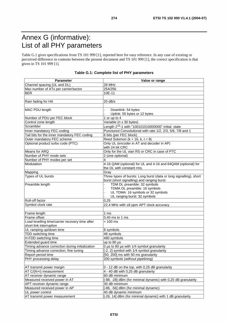
ETSI
ETSI TS 102 000 V1.4.1 (2004-07) 274
Annex G (informative): List of all PHY parameters Table G.1 gives specifications from TS 101 999 [1], reported here for easy reference. In any case of existing or perceived difference in contents between the present document and TS 101 999 [1], the correct specification is that given in TS 101 999 [1].
Table G.1: Complete list of PHY parameters
Parameter Value or range Channel spacing (UL and DL) 28 MHz Max number of ATs per carrier/sector 254/256 BER 10E-11 Rain fading for HA 20 dB/s MAC PDU length - Downlink: 54 bytes
- Uplink: 55 bytes or 12 bytes Number of PDU per FEC block 1 or up to 4 Control zone length Variable (n x 30 bytes) Scrambler Length 215-1 with "100101010000000" initial. state Inner mandatory FEC coding Punctured Convolutional with rate 1/2, 2/3, 5/6, 7/8 and 1 Tail bits for the inner mandatory FEC coding 6 bits (per FEC block) Outer mandatory FEC scheme Reed Solomon (k + 16, k, t = 8) Optional product turbo code (PTC) Only UL (encoder in AT and decoder in AP)
with 24 bit CRC Means for ARQ Only for the UL vian RS or CRC in case of PTC Number of PHY mode sets 2 (one optional) Number of PHY modes per set 4 Modulation 4-16 QAM (optional) for UL and 4-16 and 64QAM (optional) for
the DL with constant rms. Mapping Gray Types of UL bursts Three types of bursts: Long burst (data or long signalling), short
burst (short signalling) and ranging burst Preamble length - TDM DL preamble: 32 symbols
- TDMA DL preamble: 16 symbols - UL TDMA: 16 symbols or 32 symbols - UL ranging burst: 32 symbols
Roll-off factor 0,25 Symbol clock rate 22,4 MHz with ±8 ppm APT clock accuracy Frame length 1 ms Frame offset 0,40 ms to 1 ms Load levelling time/carrier recovery time after short link interruption
< 100 ms
UL ramping up/down time 8 symbols TDD switching time 48 symbols H-FDD switching time 480 symbols Extended guard time up to 80 µs Timing advance correction during initialization 0 µs to 80 µs with 1/4 symbol granularity Timing advance correction, fine tuning [-2, 2] symbol with 1/4 symbol granularity Report period time [50, 200] ms with 50 ms granularity PHY processing delay 200 symbols (without pipelining) AT transmit power margin 0 - 12 dB on the top, with 0,25 dB granularity AT C/(N+I) measurement 4 - 40 dB with 0,25 dB granularity AT receiver dynamic range 60 dB minimum Measured received power in AT [-88, -28] dBm (for minimal dynamic) with 0,25 dB granularity APT receiver dynamic range 30 dB minimum Measured received power in AP [-86, -56] dBm (for minimal dynamic) UL power control 40 dB dynamic minimum AT transmit power measurement [-26, 14] dBm (for minimal dynamic) with 1 dB granularity
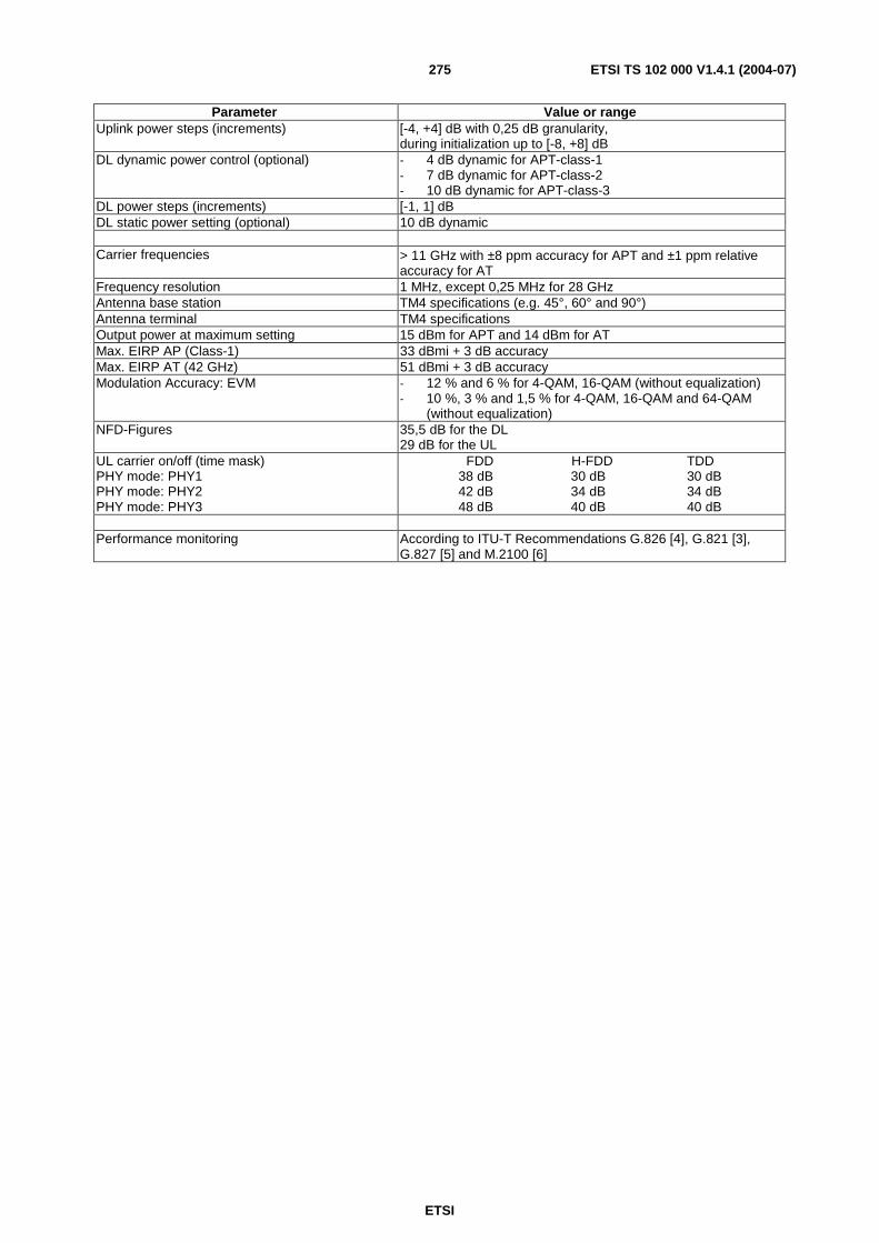
ETSI
ETSI TS 102 000 V1.4.1 (2004-07) 275
Parameter Value or range Uplink power steps (increments) [-4, +4] dB with 0,25 dB granularity,
during initialization up to [-8, +8] dB DL dynamic power control (optional) - 4 dB dynamic for APT-class-1
- 7 dB dynamic for APT-class-2 - 10 dB dynamic for APT-class-3
DL power steps (increments) [-1, 1] dB DL static power setting (optional) 10 dB dynamic Carrier frequencies > 11 GHz with ±8 ppm accuracy for APT and ±1 ppm relative
accuracy for AT Frequency resolution 1 MHz, except 0,25 MHz for 28 GHz Antenna base station TM4 specifications (e.g. 45°, 60° and 90°) Antenna terminal TM4 specifications Output power at maximum setting 15 dBm for APT and 14 dBm for AT Max. EIRP AP (Class-1) 33 dBmi + 3 dB accuracy Max. EIRP AT (42 GHz) 51 dBmi + 3 dB accuracy Modulation Accuracy: EVM - 12 % and 6 % for 4-QAM, 16-QAM (without equalization)
- 10 %, 3 % and 1,5 % for 4-QAM, 16-QAM and 64-QAM (without equalization)
NFD-Figures 35,5 dB for the DL 29 dB for the UL
UL carrier on/off (time mask) PHY mode: PHY1 PHY mode: PHY2 PHY mode: PHY3
FDD H-FDD TDD 38 dB 30 dB 30 dB 42 dB 34 dB 34 dB 48 dB 40 dB 40 dB
Performance monitoring According to ITU-T Recommendations G.826 [4], G.821 [3],
G.827 [5] and M.2100 [6]

ETSI
ETSI TS 102 000 V1.4.1 (2004-07) 276
Annex H (informative): Bibliography Bruce Schneier, "Applied Cryptography: Protocols, Algorithms, and Source Code in C", 2nd edition, John Wiley and Sons, 1996.
IEEE 802 (1990): "IEEE Standards for Local and Metropolitan Area Networks: Overview and Architecture".
ETSI TR 101 177: "Broadband Radio Access Networks (BRAN); Requirements and architectures for broadband fixed radio access networks (HIPERACCESS)".
ETSI TR 101 856: "Broadband Radio Access Networks (BRAN); Functional Requirements for Fixed Wireless Access systems below 11 GHz: HIPERMAN".
ETSI TR 101 031: "Broadband Radio Access Networks (BRAN); HIgh PErformance Radio Local Area Network (HIPERLAN) Type 2; Requirements and architectures for wireless broadband access".
ETSI TS 101 475: "Broadband Radio Access Networks (BRAN); HIPERLAN Type 2; Physical (PHY) layer".
ETSI TS 101 761-1: "Broadband Radio Access Networks (BRAN); HIPERLAN Type 2; Data Link Control (DLC) Layer; Part 1: Basic Data Transport Functions".
ETSI TS 101 761-2: "Broadband Radio Access Networks (BRAN); HIPERLAN Type 2; Data Link Control (DLC) Layer; Part 2: Radio Link Control (RLC) sublayer".
ETSI
ETSI TS 102 000 V1.4.1 (2004-07) 277
List of Figures
Figure 1: Example of cellular configuration (4 x 90 sectors) ...........................................................................21
Figure 2: Configuration model for HA systems ...............................................................................................24
Figure 3: Reference model and interfaces for HA systems ..............................................................................25
Figure 4: Protocol layer structure (for AP).......................................................................................................26
Figure 5: SDU and PDU in the protocol stack .................................................................................................34
Figure 6: Structure of MAC data PDU and long MAC signalling PDU ..........................................................35
Figure 7: Structure of short MAC signalling PDU (UL only)..........................................................................36
Figure 8: Block-diagram of the DLC-PHY interface .......................................................................................36
Figure 9: Block diagram of transmitter and receiver chain ..............................................................................39
Figure 10: Transmission of MAC PDUs in DL without TDMA option...........................................................40
Figure 11: Transmission of MAC PDUs in DL with TDMA option................................................................41
Figure 12: Transmission of MAC PDUs in UL................................................................................................43
Figure 13: Structure of RS codewords and preambles in an UL burst .............................................................44
Figure 14: MAC management message formats...............................................................................................51
Figure 15: Overview of packing, encoding, SAR and mapping on MAC signalling PDUs.............................52
Figure 16: Definition of Segmentation Control Field (SCF, 1 byte, left bit transmitted first) .........................53
Figure 17: Maps and basic DL frame structure with TDMA option ................................................................64
Figure 18: Basic UL frame structure ................................................................................................................66
Figure 19: FDD frequency assignment.............................................................................................................67
Figure 20: H-FDD operation ............................................................................................................................68
Figure 21: TDD frame sequence.......................................................................................................................68
Figure 22: TDD frame structure .......................................................................................................................69
Figure 23: DL map entry format (left bit transmitted first) ..............................................................................70
Figure 24: UL map entry format (left bit transmitted first) ..............................................................................71
Figure 25: Details of DL and UL map..............................................................................................................72
Figure 26: Relation between DL and UL frames for ARQ...............................................................................73
Figure 27: ARQ Scheduling Issue with Max Map Relevance..........................................................................74
Figure 28: ARQ map entry format (left bit transmitted first) ...........................................................................74
Figure 29: Examples of re-transmission 1 ........................................................................................................76
Figure 30: Examples of re-transmission 2 ........................................................................................................77
Figure 31: Examples of re-transmission 3 ........................................................................................................78
Figure 32: General structure of the control zone (not all details shown)..........................................................79
Figure 33: Control zone details.........................................................................................................................81
Figure 34: Bit structure of control zone (left bit transmitted first) ...................................................................82
Figure 35: FEC protection of the control zone .................................................................................................83
ETSI
ETSI TS 102 000 V1.4.1 (2004-07) 278
Figure 36: Starting times for UL bursts............................................................................................................84
Figure 37: Minimum time relevance for UL map (FDD mode) .......................................................................85
Figure 38: Maximum time relevance for UL map (FDD mode) ......................................................................86
Figure 39: Minimum time relevance for UL map (TDD mode).......................................................................87
Figure 40: Maximum time relevance for UL map (TDD mode) ......................................................................87
Figure 41: Parameters for PHY mode set description ......................................................................................89
Figure 42: Grant per terminal ...........................................................................................................................91
Figure 43: Usage of piggyback and poll-me bit by an AT ...............................................................................97
Figure 44: Contention algorithm for bandwidth request ..................................................................................99
Figure 45: Synchronization acquisition ..........................................................................................................104
Figure 46: APC identification.........................................................................................................................105
Figure 47: UL and DL parameters acquisition ...............................................................................................105
Figure 48: Frequency scanning in the context of initialization steps .............................................................106
Figure 49: First phase of ranging (normal behaviour of AP) .........................................................................114
Figure 50: Second phase of ranging ...............................................................................................................114
Figure 51: Another second phase of ranging (two grants without RlcRangingContinue message in between) .......................................................................................................................................115
Figure 52: Another second phase of ranging (two RlcRangingContinue messages without ranging grant in between) ...................................................................................................................................115
Figure 53: Detailed description of all processes during extended initialization.............................................120
Figure 54: Exemplary illustration of the dynamic behaviour of adaptive DL PHY mode change.................135
Figure 55: Exemplary illustration of the dynamic behaviour of DL ATPC ...................................................138
Figure 56: Change of PHY mode set..............................................................................................................139
Figure 57: Mandatory fields in X.509 certificates..........................................................................................151
Figure 58: System view on check of certificate..............................................................................................152
Figure 59: System view on possible handling of certificate (1) .....................................................................153
Figure 60: System view on possible handling of certificate (2) .....................................................................153
Figure 61: System view on a possible CA chain ............................................................................................154
Figure 62: Encryption of TEK with AK using 3DES algorithm ....................................................................155
Figure 63: Local view on TEK refresh allocation ..........................................................................................158
Figure 64: Local view on first TEK allocation...............................................................................................160
Figure 65: Global view on TEK exchange .....................................................................................................160
Figure 66: TEK exchange for security phase 1 ..............................................................................................161
Figure 67: CBC mode encryption of one MAC PDU with TEK....................................................................162
Figure 68: CBC mode decryption of one MAC PDU with TEK....................................................................163
Figure 69: Use of primitives ...........................................................................................................................165
ETSI
ETSI TS 102 000 V1.4.1 (2004-07) 279
List of Tables
Table 1: DLC Service Category Limitation (transmitter side) .........................................................................28
Table 2: Interface between DLC and PHY in AP (transmitter side) ................................................................37
Table 3: Interface between DLC and PHY in AP (receiver side).....................................................................37
Table 4: Interface between DLC and PHY in AT (transmitter side) ................................................................37
Table 5: Interface between DLC and PHY in AT (receiver side) ....................................................................38
Table 6: Specific CID values (16 bits) .............................................................................................................46
Table 7: Definition of Segmentation Indication (SI, 1 byte) ............................................................................53
Table 8: List of MAC management messages (protocol primitives)................................................................54
Table 9: List of DL basic MAC management messages for packing ...............................................................56
Table 10: List of UL basic MAC management messages for packing .............................................................56
Table 11: List of DL basic MAC management messages for multiple-TID message ......................................56
Table 12: Overview of connections and related parameters.............................................................................57
Table 13: Use of short and long signalling PDUs ............................................................................................57
Table 14: List of connection control service primitives ...................................................................................59
Table 15: MAC PDU header for DL (3 bytes, left bit transmitted first) ..........................................................61
Table 16: MAC PDU header for UL (4 bytes, left bit transmitted first) ..........................................................61
Table 17: PT field for MAC PDU headers .......................................................................................................62
Table 18: DIUC coding ....................................................................................................................................70
Table 19: UIUC coding ....................................................................................................................................71
Table 20: PHY mode sets .................................................................................................................................89
Table A.1: List of optional/mandatory features..............................................................................................184
Table A.2: Detailed specification of PHY parameters carried by protocol primitives ...................................185
Table A.3: Detailed specification of AP timers..............................................................................................186
Table A.4: Detailed specification of AT timers..............................................................................................186
Table C.1: Complete ASN.1 description of service primitives ......................................................................198
Table G.1: Complete list of PHY parameters.................................................................................................274

ETSI
ETSI TS 102 000 V1.4.1 (2004-07) 280
List of Diagrams
Diagram 1: MSC for the use of RSB................................................................................................................93
Diagram 2: MSC for bandwidth request message ............................................................................................94
Diagram 3: MSC for queue status report..........................................................................................................95
Diagram 4: HMSC for AT activities and states for initialization ...................................................................102
Diagram 5: MSC for the ranging principle.....................................................................................................109
Diagram 6: MSC of a ranging example with many errors..............................................................................110
Diagram 7: State diagram for ranging (AP side) ............................................................................................112
Diagram 8: State diagram for ranging (AT side)............................................................................................113
Diagram 9: MSC for PHY capabilities negotiation........................................................................................117
Diagram 10: MSC for other capabilities negotiation......................................................................................118
Diagram 11: SDL diagram for link loss reaction (AT side) (update) .............................................................123
Diagram 12: SDL diagram for link loss supervision and reaction (AP side, example)..................................124
Diagram 13: MSC for initialization command ...............................................................................................126
Diagram 14: HMSC for DL PHY mode change and measurement report .....................................................128
Diagram 15: MSC for transmission of the measurement report .....................................................................130
Diagram 16: MSC for AT initiated DL PHY mode change (to a more robust mode)....................................132
Diagram 17: MSC for AT initiated DL PHY mode change (to a more efficient mode) ................................133
Diagram 18: MSC for AP initiated DL PHY mode change (to a more robust mode)....................................134
Diagram 19: MSC for AP initiated DL PHY mode change (to a more efficient mode).................................135
Diagram 20: MSC for Correction of AT's transmit parameters......................................................................137
Diagram 21: MSC for load levelling ..............................................................................................................141
Diagram 22: HMSC for security control ........................................................................................................143
Diagram 23: MSC overview of the most important security messages..........................................................144
Diagram 24: MSC for authentication .............................................................................................................148
Diagram 25: MSC for re-authentication .........................................................................................................150
Diagram 26: MSC for TEK refresh allocation ...............................................................................................156
Diagram 27: MSC for first TEK allocation ....................................................................................................159
Diagram 28: MSC (4 entities) for AT initiated connection set up..................................................................170
Diagram 29: MSC (4 entities) for AP initiated connection set up..................................................................170
Diagram 30: MSC (4 entities) for AT initiated connection change................................................................171
Diagram 31: MSC (4 entities) for AP initiated connection change................................................................171
Diagram 32: MSC (4 entities) for AP/AT initiated connection release..........................................................172
Diagram 33: HMSC for connection control messaging..................................................................................174
Diagram 34: MSC for AT initiated Connection Establishment......................................................................178
Diagram 35: MSC for AP initiated Connection Establishment......................................................................179
ETSI
ETSI TS 102 000 V1.4.1 (2004-07) 281
Diagram 36: MSC for AT initiated connection change..................................................................................180
Diagram 37: MSC for AP initiated connection change ..................................................................................181
Diagram 38: MSC for AT initiated connection release ..................................................................................182
Diagram 39: MSC for AP initiated connection release ..................................................................................183

ETSI
ETSI TS 102 000 V1.4.1 (2004-07) 282
History
Document history
V1.1.1 June 2002 Publication
V1.2.1 September 2002 Publication
V1.3.1 December 2002 Publication
V1.4.1 July 2004 Publication