Embed Size (px)
Citation preview
ITEM #0553456
Grounded in Quality""
VENTILATION FAN UTILITECHlM MODEL #00762
Espanol p. 22
Fran9ais p. 43
ATTACH YOUR RECEIPT HERE
Serial Number ---- Purchase Date----
~ Questions, problems, missing parts? Before returning to your retailer, call our customer ~service department at 1-866-994-4148, 8 a.m.- 6 p.m., EST, Monday- Thursday, 8 a.m.-
5 p.m., EST, Friday.
AB13888 ~ UTILITECH' ] Lowes.com l!l) -·-:
1
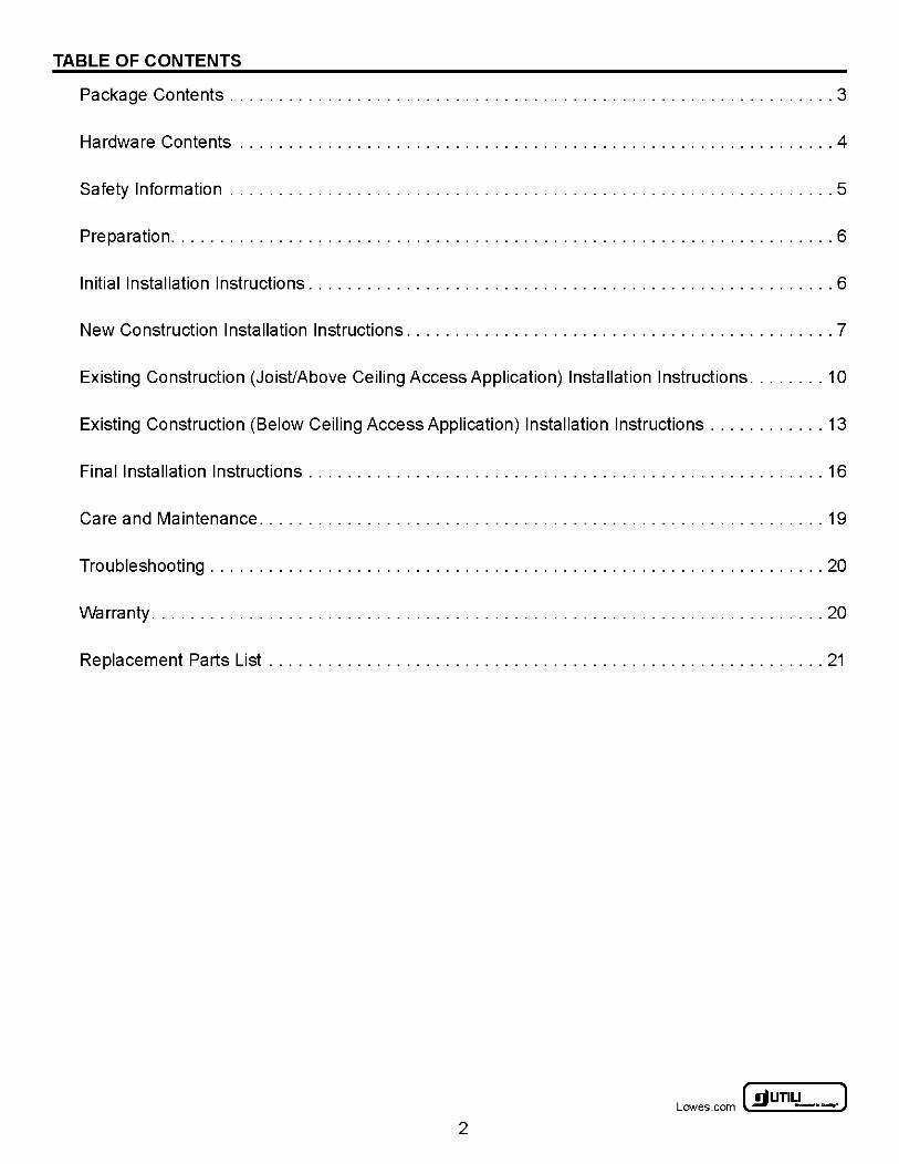
TABLE OF CONTENTS
Package Contents .............................................................. 3
Hardware Contents ............................................................. 4
Safety Information .............................................................. 5
Preparation .................................................................... 6
Initial Installation Instructions ...................................................... 6
New Construction Installation Instructions ............................................ 7
Existing Construction (Joist/Above Ceiling Access Application) Installation Instructions ........ 10
Existing Construction (Below Ceiling Access Application) Installation Instructions ............ 13
Final Installation Instructions ..................................................... 16
Care and Maintenance .......................................................... 19
Troubleshooting ............................................................... 20
Warranty ... . ............... . .. . ............... . .. . .. . ............... . .. . ..... 20
Replacement Parts List ......................................................... 21
~UTILITECH" J Lowes .com ~ - · -
2
PACKAGE CONTENTS
PART
A
B
c D
E
F
G
H
I J
K
L
M
Housing
·~ ~·
<>--0 8----c:=t>
DESCRIPTION
Motor Assembly (Preassembled to Housing (A))
Mounting Bracket (Preassembled to Housing (A))
Hanger Bar (Preassembled to Housing (A))
Duct Adaptor
Light Kit Pan
Light Kit
Template (9.5 in. x 9.5 in.)
Motor Power Connector (Preassembled to Motor Assembly (B))
Mounting Bracket Lock (Preassembled to Housing (A))
Wire Housing Cover (Preassembled to Housing (A))
Nightlight Bulb
Bulb
3
QUANTITY
1 1 1 4 1 1 1 1 1 1 1
1 2
~ UTILITECH' ] Lowes.com l!l) -·-:
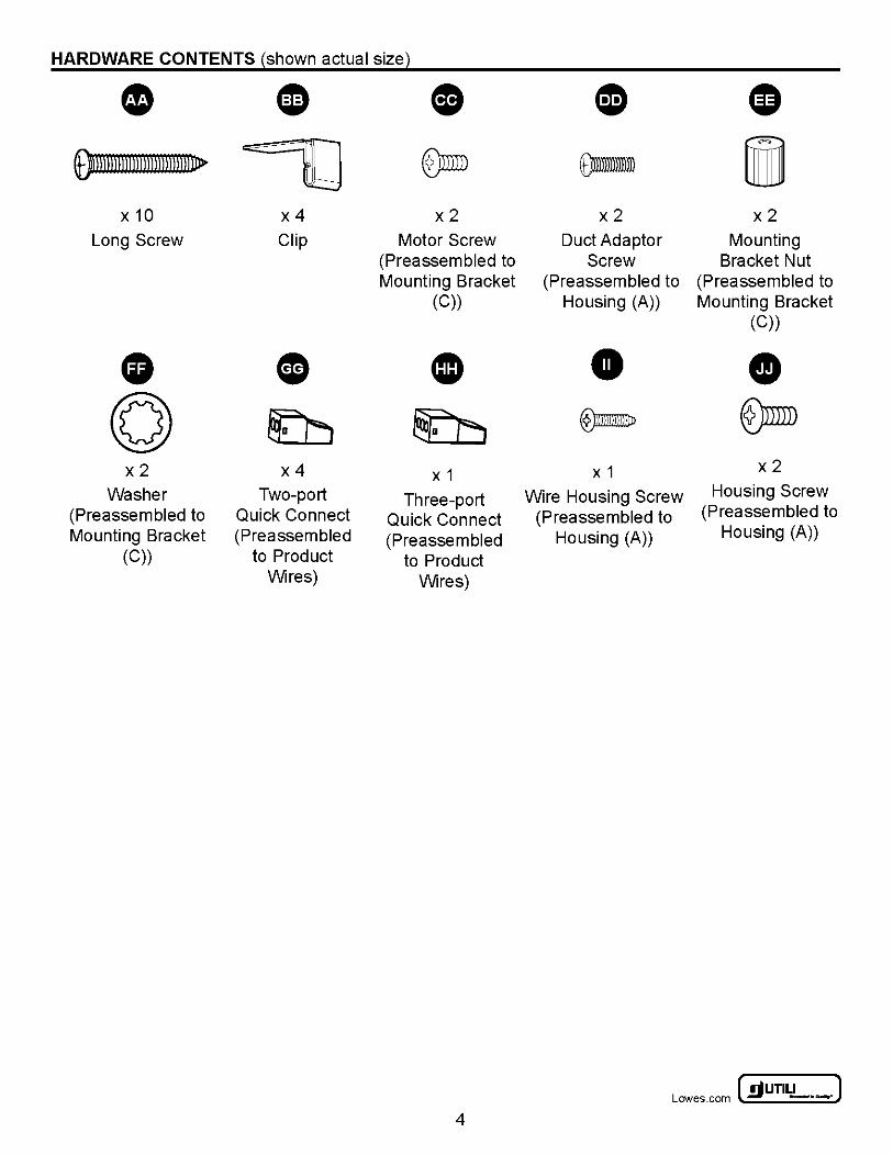
HARDWARE CONTENTS ~shown actual sizel
• ~ - 0 CD G 9mmll n nnnnll rum 11> ~ ~ om- i
x10 x4 x2 x2 x2 Long Screw Clip Motor Screw Duct Adaptor Mounting
(Preassembled to Screw Bracket Nut Mounting Bracket (Preassembled to (Preassembled to
(C)) Housing (A)) Mounting Bracket (C))
• • CD • • (Q) ~ ~ ®mm- @)mill x2 x4 X 1 X 1 x2
Washer Two-port Three-port Wire Housing Screw Housing Screw
(Preassembled to Quick Connect Quick Connect (Preassembled to (Preassembled to
Mounting Bracket (Preassem bled (Preasse m bled Housing (A)) Housing (A))
(C)) to Product to Product Wires) Wires)
~UTILITECH" J Lowes .com ~ -·-
4
A SAFETY INFORMATION
READ AND SAVE THESE INSTRUCTIONS Please read and understand this entire manual before attempting to assemble, operate, or install the product.
A WARNING: Read all safety warnings and all instructions. Failure to follow all warnings and instructions may result in electric shock, fire, and/or serious injury. Save all warnings and instructions for future use.
A WARNING -To reduce the risk of fire, electric shock, or injury to persons, observe the following:
• Use this unit only in the manner intended by the manufacturer. If you have questions, contact the manufacturer.
• Before servicing or cleaning the unit, switch the power off at the service panel and lock the service disconnecting means to prevent the power from being switched on accidentally. When the service disconnecting means cannot be locked, securely fasten a prominent warning device, such as a tag, to the service panel.
• To reduce the risk of fire or electric shock, do not use this fan with any solid-state speed control device. • All wiring must be in accordance with the National Electrical Codes "ANSI/NFPA 70-2008" and local
electrical codes. • To reduce the risk of fire, always vent fans to the exterior and in compliance with local codes. Do not
vent exhaust air into the spaces within walls, ceilings, attics, crawl spaces, or garages. • Use 120 V, 60 Hz for the electrical supply and properly ground the unit. • Before replacing an existing fan, ensure the main power has been turned off. • Failure to wire this product correctly could result in electrical shock, fire hazards, or damage to the
product. Consult a licensed electrician if you are unsure of your ability to correctly install wiring. • The fan must not be installed in a ceiling thermally insulated to a value greater than R40.
A WARNING -To reduce the risk of fire, electric shock, or injury to persons, observe the following:
• Installation work and electrical wiring must be done by qualified person(s) in accordance with all applicable codes and standards, including fire-rated construction.
• Sufficient air is needed for proper combustion and exhausting of gases through the flue (chimney) of fuel burning equipment to prevent back drafting. Follow the heating equipment manufacturer's guideline and safety standards such as those published by the National Fire Protection Association (NFPA), and the American Society for Heating, Refrigeration and Air Conditioning Engineers (ASHRAE), and the local code authorities.
• When cutting or drilling into wall or ceiling, do not damage electrical wiring and other hidden utilities. • Ducted fans must always be vented to the outdoors. • If this unit is to be installed over a tub or shower, it must be marked as appropriate for the application
and be connected to a GFCI (Ground Fault Circuit Interrupter)- protected branch circuit.
A cAUTION:
• This product is designed for installation in ceilings up to a 45° angle. • Do not mount this product in a wall. • The duct connector must point up. • Keep dry wall spray, construction dust, etc., off the power unit to avoid motor bearing damage and
noisy and/or unbalanced impellers. • For general ventilation only. Do not use to exhaust hazardous/explosive materials or vapors.
~ UTILITECH' ] Lowes.com l!l) -·-:
5
PREPARATION
Before beginning assembly of the product, make sure all parts are present. Compare parts with the package contents list and hardware contents list. If any part is missing or damaged, do not attempt to assemble the product.
Estimated Installation Time: 30 to 60 minutes
Tools Required for Assembly (not included): Phillips screwdriver, Hammer, Nails, Duct tape, Saw, Measuring tape, Pencil, Ruler
INITIAL INSTALLATION INSTRUCTIONS
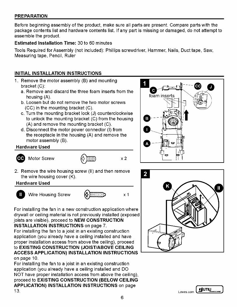
1. Remove the motor assembly (B) and mounting bracket (C): a. Remove and discard the three foam inserts from the
housing (A). b. Loosen but do not remove the two motor screws
(CC) in the mounting bracket (C). c. Turn the mounting bracket lock (J) counterclockwise
to unlock the mounting bracket (C) from the housing (A) and remove the mounting bracket (C).
d. Disconnect the motor power connector (I) from the receptacle in the housing (A) and remove the motor assembly (B).
Hardware Used
(D Motor Screw x2
2. Remove the wire housing screw (II) and then remove the wire housing cover (K).
Hardware Used
• Wire Housing Screw X 1
For installing the fan in a new construction application where drywall or ceiling material is not previously installed (exposed joists are visible), proceed to NEW CONSTRUCTION INSTALLATION INSTRUCTIONS on page 7. For installing the fan to a joist in an existing construction application (you already have a ceiling installed and have proper installation access from above the ceiling), proceed to EXISTING CONSTRUCTION (JOIST/ABOVE CEILING ACCESS APPLICATION) INSTALLATION INSTRUCTIONS on page 10. For installing the fan to a joist in an existing construction application (you already have a ceiling installed and DO NOT have proper installation access from above the ceiling), proceed to EXISTING CONSTRUCTION (BELOW CEILING APPLICATION) INSTALLATION INSTRUCTIONS on page 13.
6
~UTILITECH" J Lowes .com ~ -·-
NEW CONSTRUCTION INSTALLATION INSTRUCTIONS
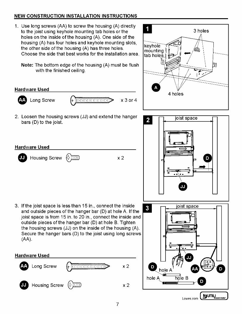
1. Use long screws (AA) to screw the housing (A) directly to the joist using keyhole mounting tab holes or the holes on the inside of the housing (A). One side of the housing (A) has four holes and keyhole mounting slots, the other side of the housing (A) has three holes. Choose the side that best works for the installation area.
Note: The bottom edge of the housing (A) must be flush with the finished ceiling.
Hardware Used
• Long Screw ~\D)))ll))l\ll))l\ll)II)))\}Jl> x 3 or 4
2. Loosen the housing screws (JJ) and extend the hanger bars (D) to the joist.
Hardware Used
• Housing Screw @)miD x2
3. If the joist space is less than 15 in., connect the inside and outside pieces of the hanger bar (D) at hole A. If the joist space is from 15 in. to 20 in., connect the inside and outside pieces of the hanger bar (D) at hole B. Tighten the housing screws (JJ) on the inside of the housing (A). Secure the hanger bars (D) to the joist using long screws (AA).
Hardware Used
Long Screw ~))lll)\l))))\))\l)))lll]))j})J> x2
Housing Screw @)miD x2
7
D
4 holes
r- joist space r-
0 II =::::::)
c: :l. - - ..... T
"" - . ~\·. -
• '-- '--
~ UTILITECH' ] Lowes.com l!l) -·-:
NEW CONSTRUCTION INSTALLATION INSTRUCTIONS
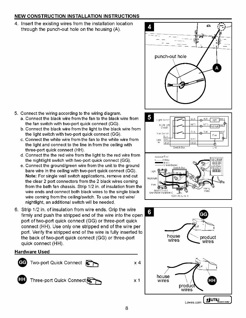
4. Insert the existing wires from the installation location through the punch-out hole on the housing (A).
5. Connect the wiring according to the wiring diagram. a. Connect the black wire from the fan to the black wire from
the fan switch with two-port quick connect (GG). b. Connect the black wire from the light to the black wire from
the light switch with two-port quick connect (GG). c. Connect the white wire from the fan to the white wire from
the light and connect to the line in from the ceiling with three-port quick connect (HH).
d. Connect the the red wire from the light to the red wire from the nightlight switch with two-port quick connect (GG).
e. Connect the ground/green wire from the unit to the ground bare wire in the ceiling with two-port quick connect (GG). Note: For single wall switch applications, remove and cut the clear 2 port connectors from the 2 black wires coming from the bath fan chassis. Strip 1/2 in. of insulation from the wire ends and connect both black wires to the single black wire coming from the ceiling/switch. To use the red wire/ nightlight, an additional switch will be needed.
6. Strip 1/2 in. of insulation from wire ends. Grip the wire firmly and push the stripped end of the wire into the open port of two-port quick connect (GG) or three-port quick connect (HH). Use only one stripped end of the wire per port. Verify the stripped end of the wire is fully inserted to the back of two-port quick connect (GG) or three-port quick connect (HH).
Hardware Used
G Two-port Quick Connect ~ x4
4JD Three-port Quick Connect~ X 1
8
house wires
~UTILITECH" J Lowes .com ~ -·-
NEW CONSTRUCTION INSTALLATION INSTRUCTIONS
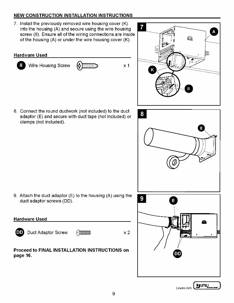
7. Install the previously removed wire housing cover (K) into the housing (A) and secure using the wire housing screw (II). Ensure all of the wiring connections are inside of the housing (A) or under the wire housing cover (K).
Hardware Used
0 Wire Housing Screw ~ X 1
8. Connect the round ductwork (not included) to the duct adaptor (E) and secure with duct tape (not included) or clamps (not included).
9. Attach the duct adaptor (E) to the housing (A) using the duct adaptor screws (DD).
Hardware Used
~ Duct Adaptor Screw x2
Proceed to FINAL INSTALLATION INSTRUCTIONS on page 16.
9
~ UTILITECH' ] Lowes.com l!l) -·-:
EXISTING CONSTRUCTION (JOIST/ABOVE CEILING ACCESS APPLICATION) INSTALLATION INSTRUCTIONS
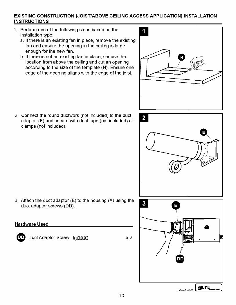
1. Perform one of the following steps based on the installation type: a. lfthere is an existing fan in place, remove the existing
fan and ensure the opening in the ceiling is large enough for the new fan.
b. lfthere is not an existing fan in place, choose the location from above the ceiling and cut an opening according to the size of the template (H). Ensure one edge of the opening aligns with the edge of the joist.
2. Connect the round ductwork (not included) to the duct adaptor (E) and secure with duct tape (not included) or clamps (not included).
3. Attach the duct adaptor (E) to the housing (A) using the duct adaptor screws (DD).
Hardware Used
G Duct Adaptor Screw ~ x2
10
G
a
~UTILITECH' J Lowes .com ~ -·-
EXISTING CONSTRUCTION (JOIST/ABOVE CEILING ACCESS APPLICATION) INSTALLATION INSTRUCTIONS
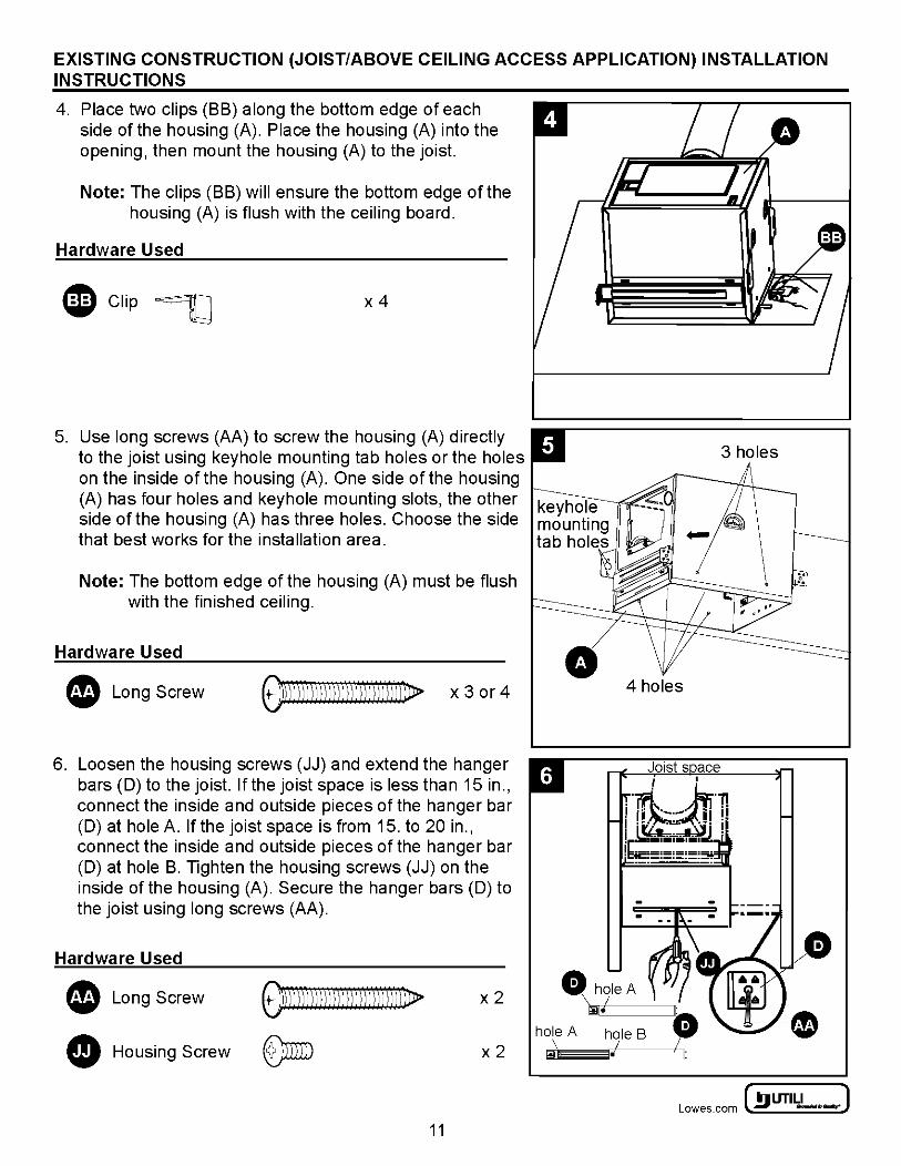
4. Place two clips (BB) along the bottom edge of each side of the housing (A). Place the housing (A) into the opening, then mount the housing (A) to the joist.
Note: The clips (BB) will ensure the bottom edge of the housing (A) is flush with the ceiling board.
Hardware Used
QD Clip ~ x4
5. Use long screws (AA) to screw the housing (A) directly to the joist using keyhole mounting tab holes or the holes on the inside of the housing (A). One side of the housing (A) has four holes and keyhole mounting slots, the other side of the housing (A) has three holes. Choose the side that best works for the installation area.
Note: The bottom edge of the housing (A) must be flush with the finished ceiling.
Hardware Used
• Long Screw OJ)j))))\)))))\))))llllllll)ll> x 3 or 4
6. Loosen the housing screws (JJ) and extend the hanger bars (D) to the joist. If the joist space is less than 15 in., connect the inside and outside pieces of the hanger bar (D) at hole A. If the joist space is from 15. to 20 in., connect the inside and outside pieces of the hanger bar (D) at hole B. Tighten the housing screws (JJ) on the inside of the housing (A). Secure the hanger bars (D) to the joist using long screws (AA).
Hardware Used
• Long Screw
fD Housing Screw
~DJ))J ll))l II I)) I II I I) I I I) I}Jl>
@miD
x2
x2
11
•
hole A
~
4 holes
hole B I
"
3 holes
~ UTILITECH' ] Lowes.com l!l) -·-:
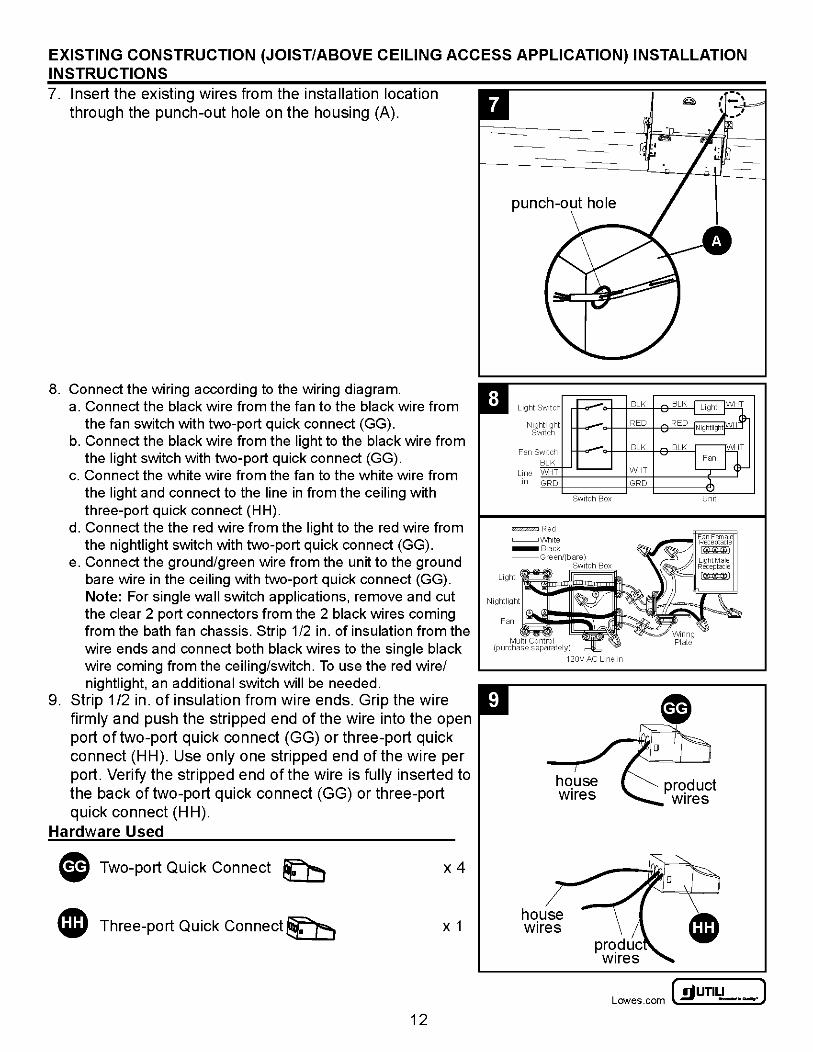
EXISTING CONSTRUCTION (JOIST/ABOVE CEILING ACCESS APPLICATION) INSTALLATION INSTRUCTIONS 7. Insert the existing wires from the installation location
through the punch-out hole on the housing (A).
8. Connect the wiring according to the wiring diagram. a. Connect the black wire from the fan to the black wire from
the fan switch with two-port quick connect (GG). b. Connect the black wire from the light to the black wire from
the light switch with two-port quick connect (GG). c. Connect the white wire from the fan to the white wire from
the light and connect to the line in from the ceiling with three-port quick connect (HH).
d. Connect the the red wire from the light to the red wire from the nightlight switch with two-port quick connect (GG).
e. Connect the ground/green wire from the unit to the ground bare wire in the ceiling with two-port quick connect (GG). Note: For single wall switch applications, remove and cut the clear 2 port connectors from the 2 black wires coming from the bath fan chassis. Strip 1/2 in. of insulation from the wire ends and connect both black wires to the single black wire coming from the ceiling/switch. To use the red wire/ nightlight, an additional switch will be needed.
9. Strip 1/2 in. of insulation from wire ends. Grip the wire firmly and push the stripped end of the wire into the open port of two-port quick connect (GG) or three-port quick connect (HH). Use only one stripped end of the wire per port. Verify the stripped end of the wire is fully inserted to the back of two-port quick connect (GG) or three-port quick connect (HH).
Hardware Used
G Two-port Quick Connect f:b x4
4JD Three-port Quick Connect~ X 1
12
punch-out hole
house wires
120V AC Line tn
~UTILITECH' J Lowes .com ~ -·-
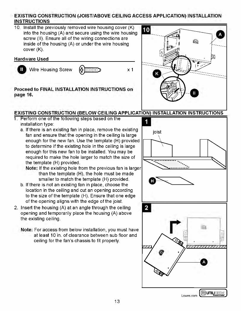
EXISTING CONSTRUCTION (JOIST/ABOVE CEILING ACCESS APPLICATION) INSTALLATION INSTRUCTIONS 10. Install the previously removed wire housing cover (K)
into the housing (A) and secure using the wire housing screw (II). Ensure all of the wiring connections are inside of the housing (A) or under the wire housing cover (K).
Hardware Used
0 Wire Housing Screw ~ X 1
Proceed to FINAL INSTALLATION INSTRUCTIONS on page 16.
EXISTING CONSTRUCTION (BELOW CEILING APPLICATION) INSTALLATION INSTRUCTIONS 1. Perform one of the following steps based on the
installation type: a. If there is an existing fan in place, remove the existing
fan and ensure that the opening in the ceiling is large enough for the new fan. Use the template (H) provided to determine if the existing hole in the ceiling is large enough for this new fan to be installed. You may be required to make the hole larger to match the size of the template (H) provided. Note: If the existing hole from the previous fan is larger
than the template (H), the hole must be made smaller to match the template (H) provided.
b. lfthere is not an existing fan in place, choose the location in the ceiling and cut an opening according to the size of the template (H). Ensure that one edge of the opening aligns with the edge of the joist.
2. Insert the housing (A) at an angle through the ceiling opening and temporarily place the housing (A) above the existing ceiling.
Note: For access from below installation, you must have at least 10 in. of clearance between sub floor and ceiling for the fan's chassis to fit properly.
13
joist
~ .
·· ~ ···--·-··-:: ...
~ UTILITECH' ] Lowes.com l!l) -·-:
EXISTING CONSTRUCTION (BELOW CEILING APPLICATION) INSTALLATION INSTRUCTIONS
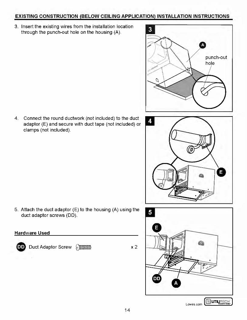
3. Insert the existing wires from the installation location through the punch-out hole on the housing (A).
4. Connect the round ductwork (not included) to the duct adaptor (E) and secure with duct tape (not included) or clamps (not included).
5. Attach the duct adaptor (E) to the housing (A) using the duct adaptor screws (DO).
Hardware Used
CD Duct Adaptor Screw ~ x2
14
punch-out hole
~UTILITECH' J Lowes .com ~ -·-
EXISTING CONSTRUCTION (BELOW CEILING APPLICATION) INSTALLATION INSTRUCTIONS
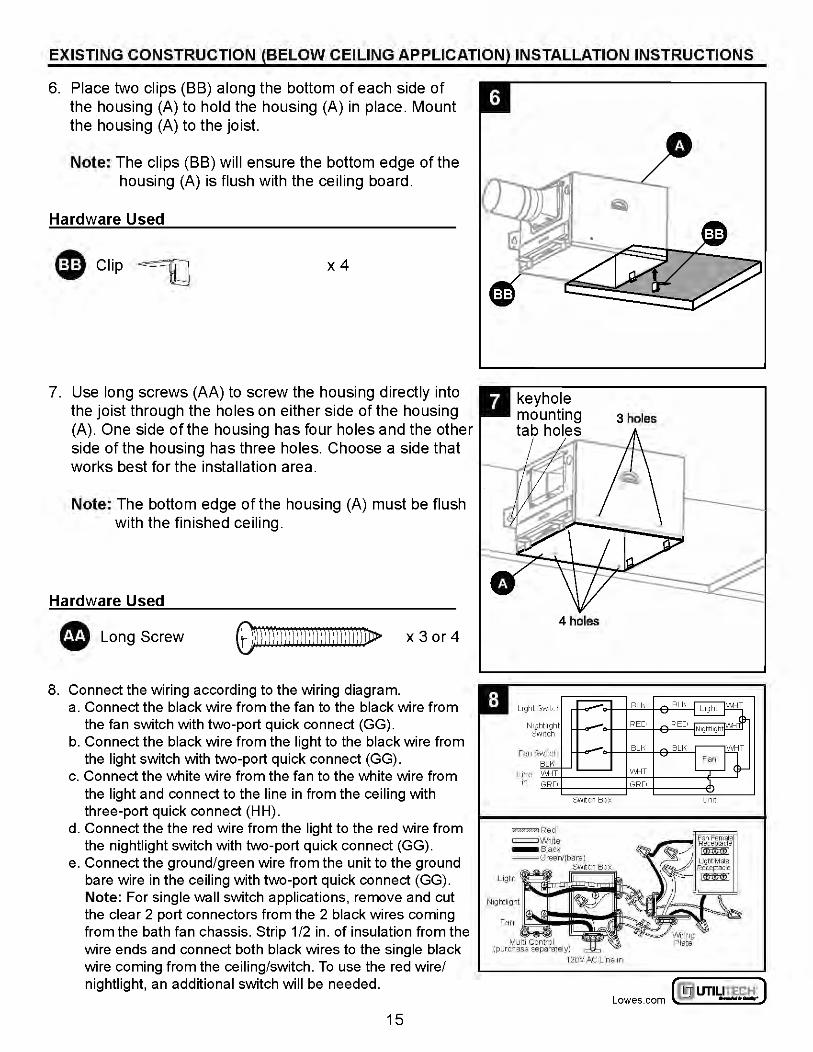
6. Place two clips (BB) along the bottom of each side of the housing (A) to hold the housing (A) in place. Mount the housing (A) to the joist.
Note: The clips (BB) will ensure the bottom edge of the housing (A) is flush with the ceiling board.
Hardware Used
eclip~ x4
7. Use long screws (AA) to screw the housing directly into the joist through the holes on either side of the housing (A). One side of the housing has four holes and the other side of the housing has three holes. Choose a side that works best for the installation area.
Note: The bottom edge of the housing (A) must be flush with the finished ceiling.
Hardware Used
• Long Screw ij})ll)l)))))j)))))))))))))))jD> x 3 or 4
8. Connect the wiring according to the wiring diagram. a. Connect the black wire from the fan to the black wire from
the fan switch with two-port quick connect (GG). b. Connect the black wire from the light to the black wire from
the light switch with two-port quick connect (GG). c. Connect the white wire from the fan to the white wire from
the light and connect to the line in from the ceiling with three-port quick connect (H H).
d. Connect the the red wire from the light to the red wire from the nightlight switch with two-port quick connect (GG).
e. Connect the ground/green wire from the unit to the ground bare wire in the ceiling with two-port quick connect (GG). Note: For single wall switch applications, remove and cut the clear 2 port connectors from the 2 black wires coming from the bath fan chassis. Strip 1/2 in. of insulation from the wire ends and connect both black wires to the single black wire coming from the ceiling/switch. To use the red wire/ nightlight, an additional switch will be needed.
15
4 holes
~ UTILITECH' ] Lowes.com l!l) -·-:
EXISTING CONSTRUCTION (BELOW CEILING APPLICATION) INSTALLATION INSTRUCTIONS
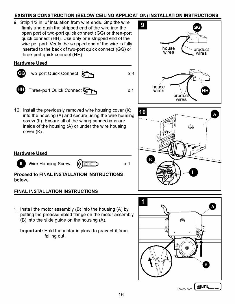
9. Strip 1/2 in. of insulation from wire ends. Grip the wire firmly and push the stripped end of the wire into the open port of two-port quick connect (GG) or three-port quick connect (HH). Use only one stripped end of the wire per port. Verify the stripped end of the wire is fully inserted to the back of two-port quick connect (GG) or three-port quick connect (HH).
Hardware Used
G Two-port Quick Connect ~ x4
4JD Three-port Quick Connect~ X 1
10. Install the previously removed wire housing cover (K) into the housing (A) and secure using the wire housing screw (II). Ensure all of the wiring connections are inside of the housing (A) or under the wire housing cover (K).
Hardware Used
0 Wire Housing Screw ~
Proceed to FINAL INSTALLATION INSTRUCTIONS below.
FINAL INSTALLATION INSTRUCTIONS
X 1
1. Install the motor assembly (B) into the housing (A) by putting the preassembled flange on the motor assembly (B) into the slide guide on the housing (A).
Important: Hold the motor in place to prevent it from falling out.
16
house wires
~UTILITECH' J Lowes .com ~ -·-
FINAL INSTALLATION INSTRUCTIONS
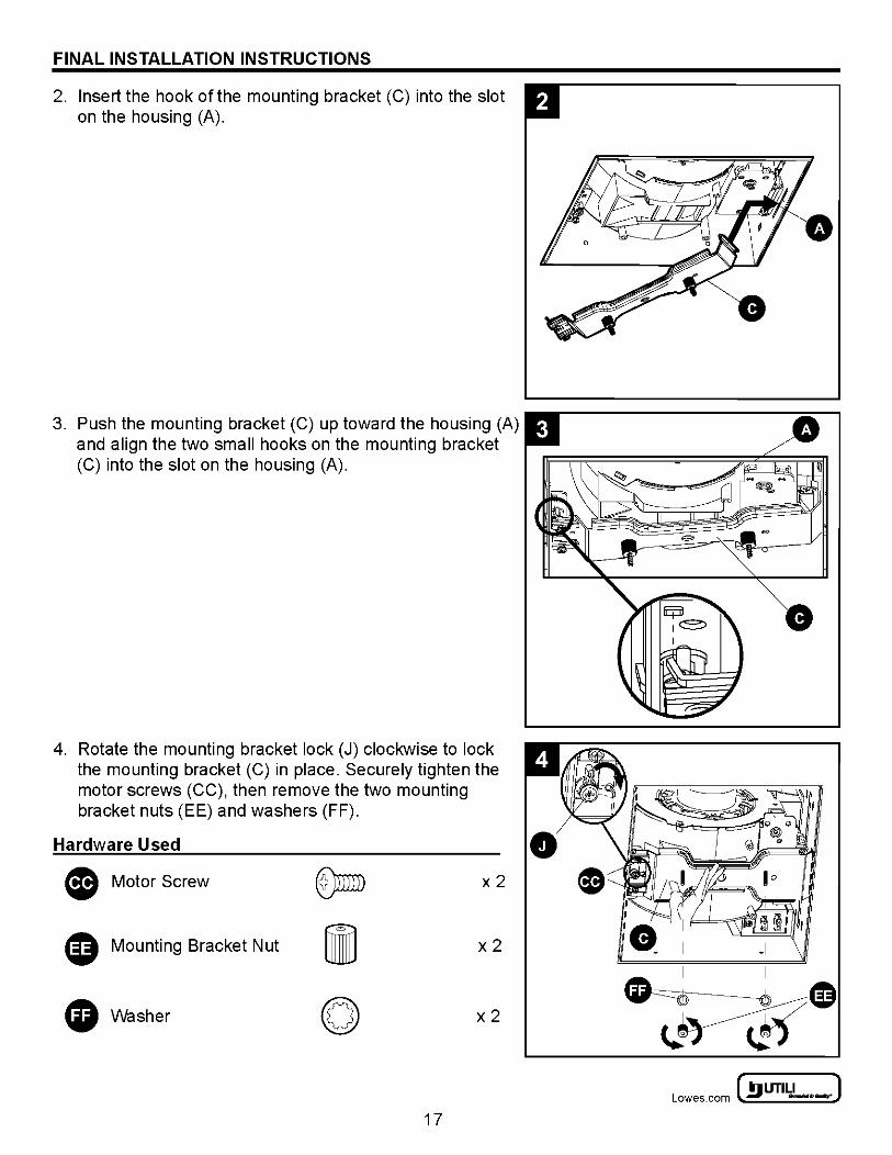
2. Insert the hook of the mounting bracket (C) into the slot on the housing (A).
3. Push the mounting bracket (C) up toward the housing (A) and align the two small hooks on the mounting bracket (C) into the slot on the housing (A).
4. Rotate the mounting bracket lock (J) clockwise to lock the mounting bracket (C) in place. Securely tighten the motor screws (CC), then remove the two mounting bracket nuts (EE) and washers (FF).
Hardware Used
(8 Motor Screw x2
0 Mounting Bracket Nut x2
G Washer x2
17
0
~ UTILITECH' ] Lowes.com l!l) -·-:
FINAL INSTALLATION INSTRUCTIONS
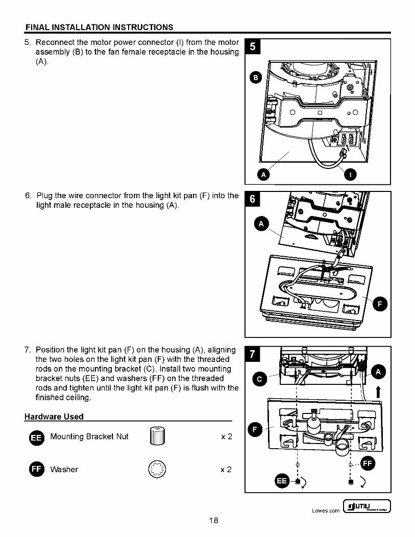
5. Reconnect the motor power connector (I) from the motor assembly (B) to the fan female receptacle in the housing (A).
6. Plug the wire connector from the light kit pan (F) into the light male receptacle in the housing (A).
7. Position the light kit pan (F) on the housing (A), aligning the two holes on the light kit pan (F) with the threaded rods on the mounting bracket (C). Install two mounting bracket nuts (EE) and washers (FF) on the threaded 8 rods and tighten until the light kit pan (F) is flush with the finished ceiling.
Hardware Used
0 Mounting Bracket Nut x2 0
0 Washer x2
18
I
tl )
~UTILITECH" J Lowes .com ~ -·-
FINAL INSTALLATION INSTRUCTIONS
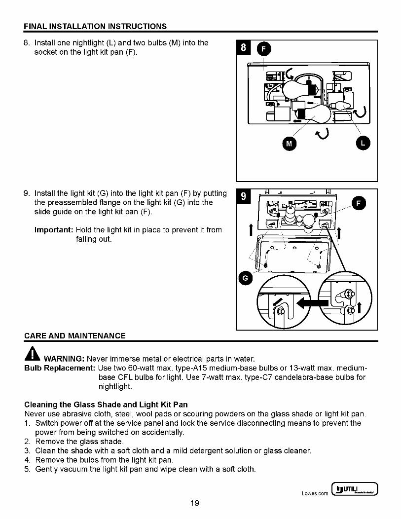
8. Install one nightlight (L) and two bulbs (M) into the socket on the light kit pan (F).
9. Install the light kit (G) into the light kit pan (F) by putting the preassembled flange on the light kit (G) into the slide guide on the light kit pan (F).
0
• 0
Important: Hold the light kit in place to prevent it from falling out.
t ~-----~.-~~ / _1
c ____ O c
CARE AND MAINTENANCE
A WARNING: Never immerse metal or electrical parts in water. Bulb Replacement: Use two 60-watt max. type-A15 medium-base bulbs or 13-watt max. medium
base CFL bulbs for light. Use 7-watt max. type-C7 candelabra-base bulbs for nightlight.
Cleaning the Glass Shade and Light Kit Pan Never use abrasive cloth, steel, wool pads or scouring powders on the glass shade or light kit pan. 1. Switch power off at the service panel and lock the service disconnecting means to prevent the
power from being switched on accidentally. 2. Remove the glass shade. 3. Clean the shade with a soft cloth and a mild detergent solution or glass cleaner. 4. Remove the bulbs from the light kit pan. 5. Gently vacuum the light kit pan and wipe clean with a soft cloth.
~ UTILITECH' ] Lowes.com l!l) -·-:
19
CARE AND MAINTENANCE
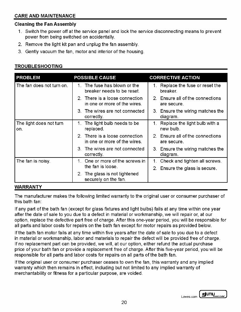
Cleaning the Fan Assembly
1. Switch the power off at the service panel and lock the service disconnecting means to prevent power from being switched on accidentally.
2. Remove the light kit pan and unplug the fan assembly.
3. Gently vacuum the fan, motor and interior of the housing.
TROUBLESHOOTING
PROBLEM POSSIBLE CAUSE CORRECTIVE ACTION
The fan does not turn on. 1. The fuse has blown or the 1. Replace the fuse or reset the breaker needs to be reset. breaker.
2. There is a loose connection 2. Ensure all of the connections in one or more of the wires. are secure.
3. The wires are not connected 3. Ensure the wiring matches the correctly. diagram.
The light does not turn 1. The light bulb needs to be 1. Replace the light bulb with a on. replaced. new bulb.
2. There is a loose connection 2. Ensure all of the connections in one or more of the wires. are secure.
3. The wires are not connected 3. Ensure the wiring matches the correctly. diagram.
The fan is noisy. 1. One or more of the screws in 1. Check and tighten all screws. the fan is loose. 2. Ensure the glass is secure.
2. The glass is not tightened securely on the fan.
WARRANTY
The manufacturer makes the following limited warranty to the original user or consumer purchaser of this bath fan:
If any part of the bath fan (except for glass fixtures and light bulbs) fails at any time within one year after the date of sale to you due to a defect in material or workmanship, we will repair or, at our option, replace the defective part free of charge. After this one-year period, you will be responsible for all parts and labor costs for repairs on the bath fan except for motor repairs as provided below.
If the bath fan motor fails at any time within five years after the date of sale to you due to a defect in material or workmanship, labor and materials to repair the defect will be provided free of charge. If no replacement part can be provided, we will, at our option, either refund the actual purchase price of your bath fan or provide a replacement free of charge. After this five-year period, you will be responsible for all parts and labor costs for repairs on all parts of the bath fan.
If the original user or consumer purchaser ceases to own the fan, this warranty and any implied warranty which then remains in effect, including but not limited to any implied warranty of merchantability or fitness for a particular purpose, are voided.
~UTILITECH" J Lowes .com ~ -·-
20
REPLACEMENT PARTS LIST
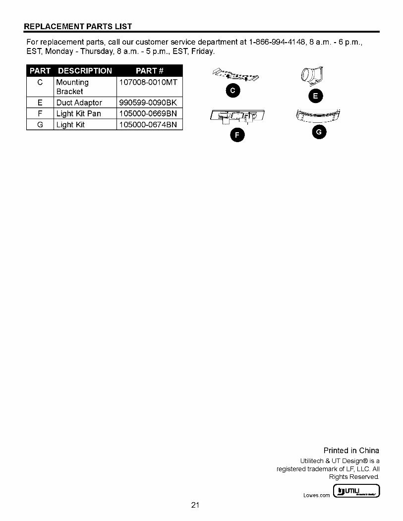
For replacement parts, call our customer service department at 1-866-994-4148, 8 a.m.- 6 p.m., EST, Monday- Thursday, 8 a.m. - 5 p.m., EST, Friday.
PART DESCRIPTION
c Mounting Bracket
E Duct Adaptor
F Light Kit Pan
G Light Kit
PART#
1 07008-001 OMT
990599-0090BK
1 05000-0669BN
1 05000-067 4BN
21
Printed in China Utilitech & UT Design® is a
registered trademark of LF, LLC. All Rights Reserved.
r m UTILITECH' ] Lowes.com ll:bl -·-:
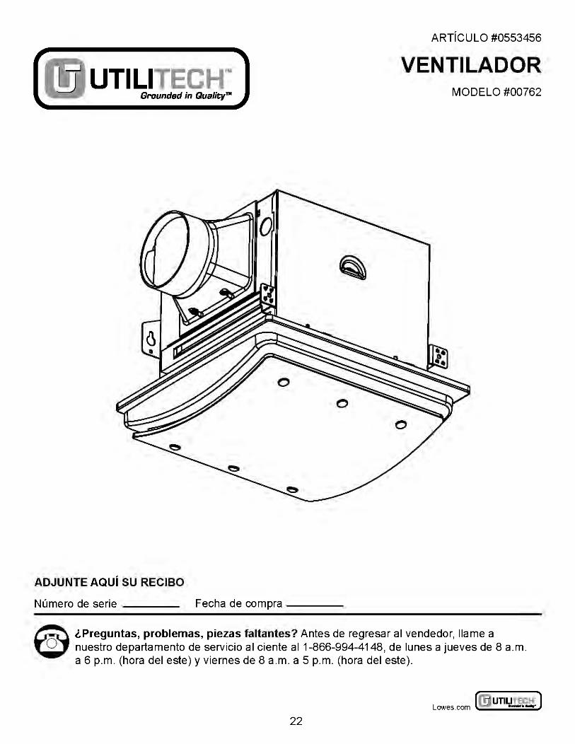
ARTICULO #0553456
Grounded in Qualitym
VENTILADOR UTILITECH™ MODELO #00762
ADJUNTE AQUi SU RECIBO
Numero de serie ___ _ Fecha de compra ----
~ l.Preguntas, problemas, piezas faltantes? Antes de regresar al vendedor, llame a ~ nuestro departamento de servicio al ciente al1-866-994-4148, de lunes a jueves de 8 a.m.
a 6 p.m. (hera del este) y viernes de 8 a.m. a 5 p.m. (hera del este).
~UTILITECH' ) Lowes .com l:JJ -·-
22
CONTENIDO
Contenido del paquete .......................................................... 24
Aditamentos .................................................................. 25
Informacion de seguridad ........................................................ 26
Preparaci6n .................................................................. 27
lnstrucciones para Ia instalaci6n inicial ............................................. 27
lnstrucciones para Ia instalaci6n en construcciones nuevas ............................. 28
lnstrucciones de instalaci6n para construcciones existentes (aplicaciones con acceso sabre el techo/vigueta) ................................................................. 31
lnstrucciones de instalaci6n para construcciones existentes (aplicaciones con acceso bajo el techo) ....................................................................... 34
lnstrucciones para Ia instalaci6n final .............................................. 37
Cuidado y mantenimiento .. . .. . .. . ............... . .. . ............... . .. . .. . ..... 40
Detecci6n de problemas ........................................................ 41
Garantfa ..................................................................... 41
Lista de piezas de repuesto ...................................................... 42
~UTILITECH" J Lowes .com ~ - · -
23
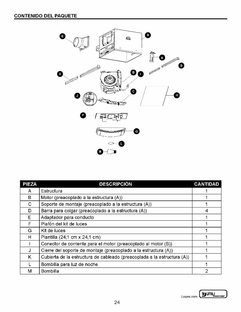
CONTENIDO DEL PAQUETE
PIEZA
A
B
c D
E
F
G
H
I j
K
L
M
Estruetura
·~ ~·
<>--0 8----c:=t>
DESCRIPCION
Motor (preaeoplado a Ia estruetura (A))
Soporte de montaje (preaeoplado a Ia estruetura (A))
Barra para eolgar (preaeoplado a Ia estruetura (A))
Adaptador para eondueto
Plaf6n del kit de luees
Kit de luees
Plantilla (24,1 em x 24,1 em)
Coneetor de eorriente para el motor (preaeoplado al motor (B))
Cierre del soporte de montaje (preaeoplado a Ia estruetura (A))
CANTIDAD
1
1
1
4
1
1
1
1
1
1
Cubierta de Ia estruetura de eableado (preaeoplada a Ia estruetura (A)) 1
Bombilla para luz de noehe 1
Bombilla 2
~ UTILITECH' ] Lowes.com l!l) -·-:
24
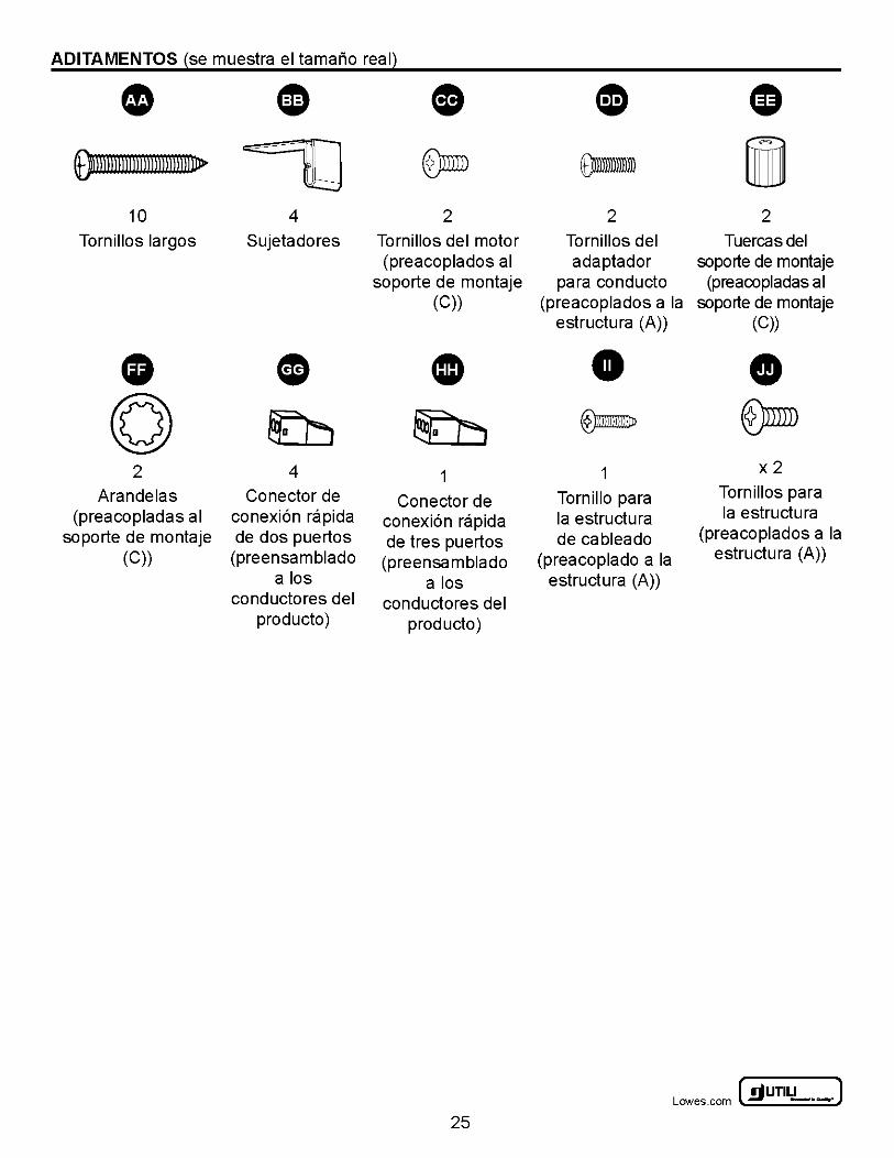
ADITAMENTOS ~se muestra el tamario reaQ
• ~ - 0 CD G 9mmll n nnnnl 1 rum 11> ~ ~ om- i
10 4 2 2 2
Tornillos largos Sujetadores Tornillos del motor Tornillos del Tuercasdel (preacoplados al adaptador soporte de montaje
soporte de montaje para conducto (preacopladas al (C)) (preacoplados a Ia soporte de montaje
estructura (A)) (C))
• • CD • • (Q) ~ ~ ®mm- @)mill 2 4 1 1 x2
Arandelas Conector de Conector de Tornillo para Tornillos para
(preacopladas al conexi6n rapida conexi6n rapida Ia estructura Ia estructura
soporte de montaje de dos puertos de tres puertos de cableado (preacoplados a Ia
(C)) (preensam blade (preensamblado (preacoplado a Ia estructura (A))
a los a los estructura (A)) conductores del conductores del
producto) producto)
~UTILITECH" J Lowes .com ~ -·-
25
INFORMACION DE SEGURIDAD
LEA Y CONSERVE ESTAS INSTRUCCIONES Por favor, lea y comprenda este manual completamente antes de proceder a ensamblar, usar o instalar el producto.
A ADVERTENCIA: Lea todas las instrucciones y advertencias de seguridad. El incumplimiento de estas advertencias e instrucciones pudiera ocasionar descargas electricas, incendios y/o lesiones graves. Conserve todas las advertencias e instrucciones para su referencia futura.
A ADVERTENCIA- Para reducir el riesgo de incendios, descargas electricas o lesiones, preste atenci6n a lo siguiente:
• Use esta unidad solo de Ia manera para Ia que ha sido concebida por el fabricante. Si tiene preguntas, comunfquese con el fabricante.
• Antes de limpiar o dar servicio a esta unidad, desconecte Ia electricidad en el panel de servicio y bloquee el acceso al mismo para evitar que alguien conecte Ia electricidad accidentalmente. De no ser posible bloquear el acceso al panel de servicio, coloque firmemente un aviso visible, como un letrero, en el panel de servicio.
• Para reducir el riesgo de incendios o descargas electricas, no use este ventilador con ningun aparato de control de velocidad de estado solido.
• Todo el alambrado debe cumplir con Ia norma "ANSI/NFPA 70-2008" del Codigo Electrico Nacional y con los codigos electricos locales.
• Para reducir el riesgo de incendios, conecte siempre los ventiladores a ventilas exteriores y en cumplimiento con los codigos locales. No dirija el a ire del extractor hacia el interior de paredes, techos, aticos, semisotanos ni garajes.
• Use corriente de 120 V y 60 Hz y conecte adecuadamente esta unidad a tierra. • Antes de reemplazar un ventilador existente, asegurese de desconectar Ia fuente principal de corriente. • El alambrado incorrecto de este producto podrfa ocasionar descargas electricas, riesgos de incendios o darios al
producto. Si no esta seguro de poder instalar correctamente el alambrado, contacte a un electricista certificado. • El ventilador nose debe instalar en techos con un aislamiento termico de un valor superior a R40.
A ADVERTENCIA- Para reducir el riesgo de incendios, descargas electricas o lesiones, preste atenci6n .. a lo siguiente:
• La instalacion y el cableado electrico deben ser realizados por una(s) persona(s) calificada(s) y en cumplimiento con todos los codigos y normas aplicables, incluyendo Ia calificacion de resistencia a incendios de Ia edificacion.
• Se necesita suficiente aire para Ia combustion adecuada y para el escape de los gases a traves del tiro (chimenea) de los equipos que quemen combustibles para evitar asf el retorno de los gases. Siga las indicaciones del fabricante del equipo de calefaccion y las normas de seguridad, tales como las publicadas porIa Asociacion Nacional de Proteccion contra el Fuego (NFPA) y Ia Sociedad Americana de lngenieros en Calefaccion, Refrigeracion y AireAcondicionado (ASH RAE) asf como los codigos locales.
• Cuando corte o taladre una pared o techo, no dane los alambres electricos ni otras instalaciones ocultas. • Los ventiladores con conducto deben conectarse siempre a ventilas exteriores. • Si se va a instalar esta unidad sobre una bariera o ducha, Ia unidad debe estar marcada como apropiada para
dicha aplicacion y se debe conectar a un circuito protegido por un interruptor de circuito de falla conectado a tierra (GFCI).
A PRECAUCION:
• Este producto esta diseriado para instalarse en techos con un angulo de hasta 45 grados. • No instale este producto en paredes. • El conector del conducto debe apuntar hacia arriba. • Aleje los atomizadores para paneles de yeso, el polvo de Ia construccion, etc. de Ia unidad de corriente para
evitar darios al motor y evitar propulsores ruidosos y/o desbalanceados. • Para Ia ventilacion general solamente. No lo use para expulsar vapores ni materiales peligrosos/explosivos.
~ UTILITECH' ] Lowes.com l!l) -·-:
2 6
PREPARATION
Antes de comenzar el ensamblaje del producto, asegurese de tener todas las piezas. Compare las piezas con Ia lista del contenido del paquete y Ia lista de aditamentos. Si hubiera piezas faltantes o danadas, no intente ensamblar el producto. Tiempo aproximado de instalaci6n: De 30 a 60 minutos
Herramientas necesarias para el ensamblaje (nose incluyen): Destornillador Phillips, martillo, clavos, cinta para conductos, sierra, cinta metrica, lapiz, regia.
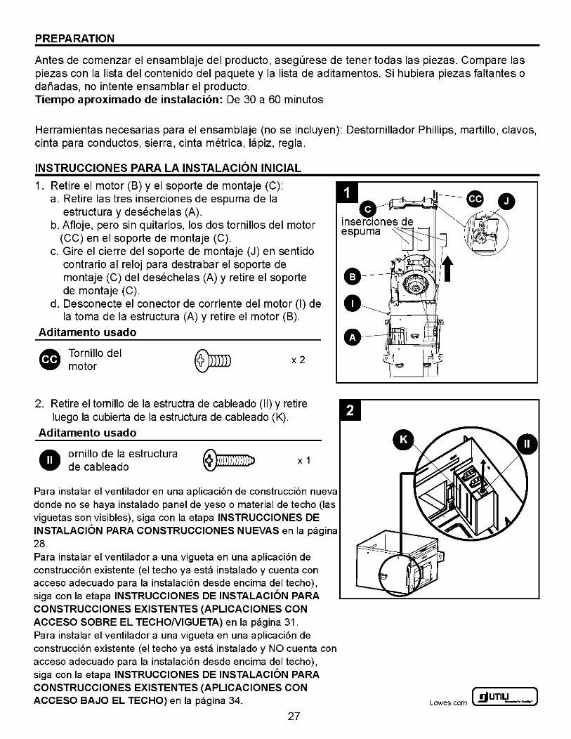
INSTRUCCIONES PARA LA INSTALACION INICIAL
1. Retire el motor (B) y el soporte de montaje (C): a. Retire las tres inserciones de espuma de Ia
estructura y desechelas (A). b. Afloje, pero sin quitarlos, los dos tornillos del motor
(CC) en el soporte de montaje (C). c. Gire el cierre del soporte de montaje (J) en sentido
contrario al reloj para destrabar el soporte de montaje (C) del desechelas (A) y retire el soporte de montaje (C).
d. Desconecte el conector de corriente del motor (I) de Ia toma de Ia estructura (A) y retire el motor (B).
Aditamento usado
~ Tornillo del 'iii' motor
x2
2. Retire el tornillo de Ia estructra de cableado (II) y retire luego Ia cubierta de Ia estructura de cableado (K).
Aditamento usado
• ornillo de Ia estructura de cableado
X 1
Para instalar el ventilador en una aplicaci6n de construcci6n nueva donde no se haya instalado panel de yeso o material de techo (las viguetas son visibles), siga con Ia etapa INSTRUCCIONES DE INSTALACION PARA CONSTRUCCIONES NUEVAS en Ia pagina 28. Para instalar el ventilador a una vigueta en una aplicaci6n de construcci6n existente (el techo ya esta instalado y cuenta con acceso adecuado para Ia instalaci6n desde encima del techo), siga con Ia etapa INSTRUCCIONES DE INSTALACION PARA CONSTRUCCIONES EXISTENTES (APLICACIONES CON ACCESO SOBRE EL TECHONIGUETA) en Ia pagina 31. Para instalar el ventilador a una vigueta en una aplicaci6n de construcci6n existente (el techo ya esta instalado y NO cuenta con acceso adecuado para Ia instalaci6n desde encima del techo), siga con Ia etapa INSTRUCCIONES DE INSTALACION PARA CONSTRUCCIONES EXISTENTES (APLICACIONES CON ACCESO BAJO EL TECHO) en Ia pagina 34.
27
0 0
~UTILITECH" J Lowes .com ~ -·-
INSTRUCCIONES PARA LA INSTALACION EN CONSTRUCCIONES NUEVAS
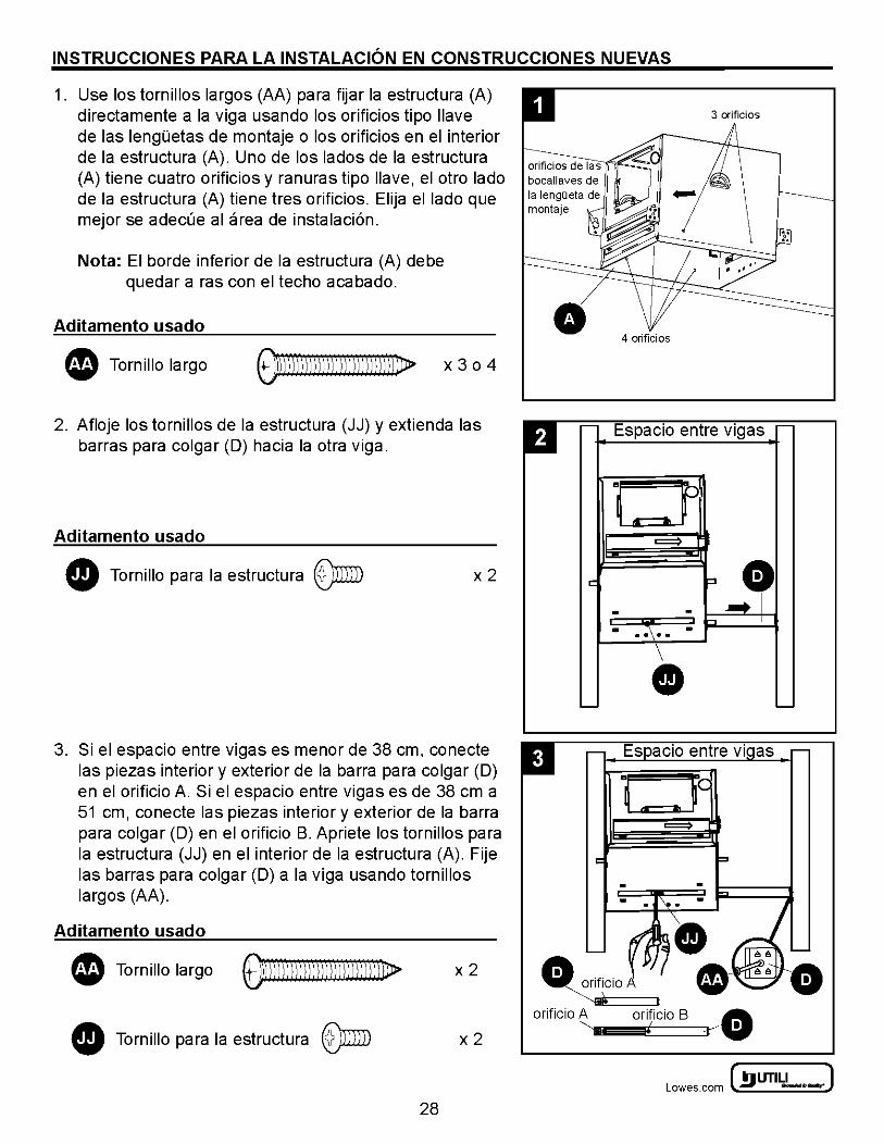
1. Use los tornillos largos (AA) para fijar Ia estructura (A) directamente a Ia viga usando los orificios tipo I lave de las lenguetas de montaje o los orificios en el interior de Ia estructura (A). Uno de los Iadas de Ia estructura (A) tiene cuatro orificios y ranuras tipo llave, el otro lade de Ia estructura (A) tiene tres orificios. Elija el lade que mejor se adecue al area de instalaci6n.
Nota: El borde inferior de Ia estructura (A) debe quedar a ras con el techo acabado.
Aditamento usado
• Tornillo largo ~\Dj))))j)l)))j))))lJ)))j))}Jl> X 3 0 4
2. Afloje los tornillos de Ia estructura (JJ) y extienda las barras para colgar (D) hacia Ia otra viga.
Aditamento usado
• Tornillo para Ia estructura ®mill x2
3. Si el espacio entre vigas es me nor de 38 em, conecte las piezas interior y exterior de Ia barra para colgar (D) en el orificio A. Si el espacio entre vigas es de 38 em a 51 em, conecte las piezas interior y exterior de Ia barra para colgar (D) en el orificio B. Apriete los tornillos para Ia estructura (JJ) en el interior de Ia estructura (A). Fije las barras para colgar (D) a Ia viga usando tornillos largos (AA).
Aditamento usado
Tornillo largo ~))lll)\l))))\))\l)))lll]))I.DJ> x2
Tornillo para Ia estructura ®mill x2
28
D r- Espacio entre vigas r-
0 II =::::::)
c: :l. - - ..... T
"" - . ~\·. -
• '-- '--
. orificio '----;@:sF ==::::Jt
orificio A orificio B A ~~~~~~/ ===:::::::Jr-0
~ UTILITECH' ] Lowes.com l!l) -·-:
INSTRUCCIONES PARA LA INSTALACION EN CONSTRUCCIONES NUEVAS
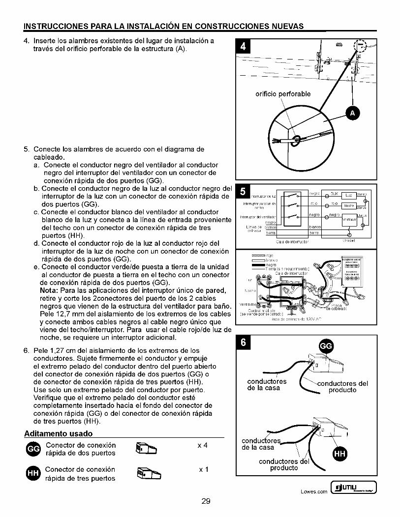
4. lnserte los alambres existentes del Iugar de instalaci6n a traves del orificio perforable de Ia estructura (A).
5. Conecte los alambres de acuerdo con el diagrama de cableado. a. Conecte el conductor negro del ventilador al conductor
negro del interruptor del ventilador con un conector de conexi6n rapida de dos puertos (GG).
b. Conecte el conductor negro de Ia luz al conductor negro del interruptor de Ia luz con un conector de conexi6n rapida de dos puertos (GG).
c. Conecte el conductor blanco del ventilador al conductor blanco de Ia luz y conecte a Ia lfnea de entrada proveniente del techo con un conector de conexi6n rapida de tres puertos (HH).
d. Conecte el conductor rojo de Ia luz al conductor rojo del interruptor de Ia luz de noche con un conector de conexi6n rapida de dos puertos (GG).
e. Conecte el conductor verde/de puesta a tierra de Ia unidad al conductor de puesta a tierra en el techo con un conector
de conexi6n rapida de dos puertos (GG). Nota: Para las aplicaciones del interruptor unico de pared, retire y corte los 2conectores del puerto de los 2 cables negros que vienen de Ia estructura del ventilador para bario. Pele 12,7 mm del aislamiento de los extremos de los cables y conecte ambos cables negros al cable negro unico que viene del techo/interruptor. Para usar el cable rojo/de luz de noche, se requiere un interruptor adicional.
6. Pele 1 ,27 em del aislamiento de los extremos de los conductores. Sujete firmemente el conductor y empuje el extremo pelado del conductor dentro del puerto abierto del conector de conexi6n rapida de dos puertos (GG) o de conector de conexi6n rapida de tres puertos (HH). Use solo un extremo pelado del conductor por puerto. Verifique que el extremo pelado del conductor este completamente insertado hacia el fondo del conector de conexi6n rapida (GG) o del conector de conexi6n rapida de tres puertos (H H).
Aditamento usado
Conector de conexi6n rapida de dos puertos
Conector de conexi6n rapida de tres puertos
x4
X 1
29
Caja de 1nterruptor
rz<Z'Z'Z'Z?.J f OJO
= blanco
Luz
Ventilador
Control multiple (se vende por separado)
Linea de entrada de 120V AC
onductores del producto
~UTILITECH' J Lowes .com ~ -·-
INSTRUCCIONES PARA LA INSTALACION EN CONSTRUCCIONES NUEVAS
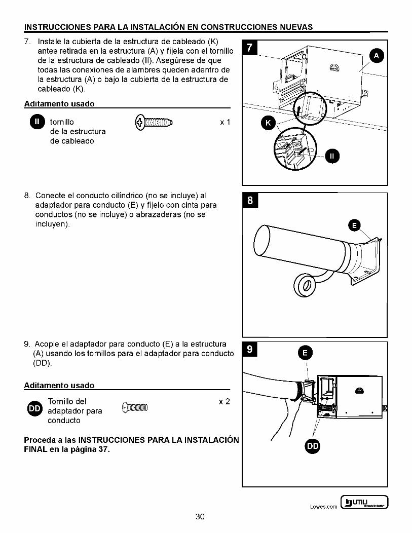
7. lnstale Ia cubierta de Ia estructura de cableado (K) antes retirada en Ia estructura (A) y ffjela con el tornillo de Ia estructura de cableado (II). Asegurese de que todas las conexiones de alambres queden adentro de Ia estructura (A) o bajo Ia cubierta de Ia estructura de cableado (K).
Aditamento usado
tornillo de Ia estructura de cableado
8. Conecte el conducto cilfndrico (nose incluye) al adaptador para conducto (E) y ffjelo con cinta para conductos (no se incluye) o abrazaderas (no se incluyen).
X 1
9. Acople el adaptador para conducto (E) a Ia estructura (A) usando los tornillos para el adaptador para conducto (DO).
Aditamento usado
I!!\ Tornillo del ~ adaptador para
conducto
x2
Proceda a las INSTRUCCIONES PARA LA INSTALACION FINAL en Ia pagina 37.
30
~ UTILITECH' ] Lowes.com l!l) -·-:
INSTRUCCIONES DE INSTALACION PARA CONSTRUCCIONES EXISTENTES (APLICACIONES CON ACCESO SOBRE EL TECHONIGUETA)
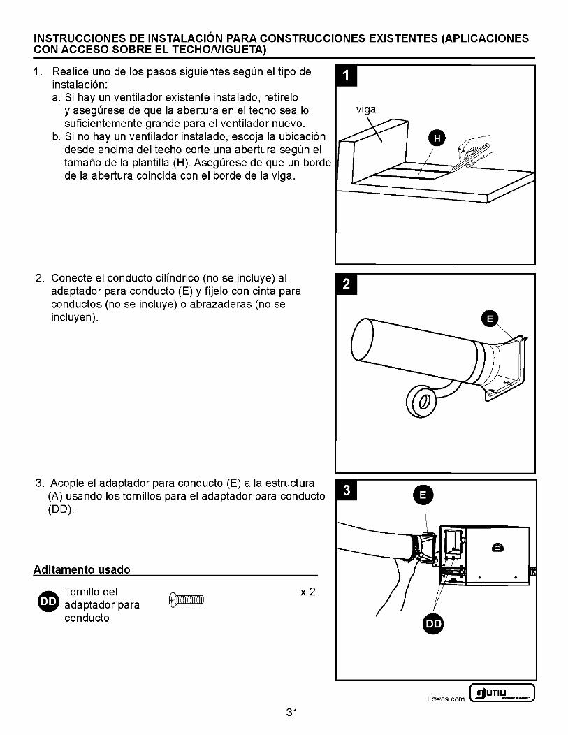
1. Realice uno de los pasos siguientes segun el tipo de instalaci6n: a. Si hay un ventilador existente instalado, retfrelo
y asegurese de que Ia abertura en el techo sea lo suficientemente grande para el ventilador nuevo.
b. Si no hay un ventilador instalado, escoja Ia ubicaci6n desde encima del techo corte una abertura segun el tamario de Ia plantilla (H). Asegurese de que un borde de Ia abertura coincida con el borde de Ia viga.
2. Conecte el conducto cilfndrico (nose incluye) al adaptador para conducto (E) y ffjelo con cinta para conductos (no se incluye) o abrazaderas (nose incluyen).
3. Acople el adaptador para conducto (E) a Ia estructura (A) usando los tornillos para el adaptador para conducto (DD).
Aditamento usado
J!!\ Tornillo del 'i6i' adaptador para
conducto
x2
31
G
a
~UTILITECH' J Lowes .com ~ -·-
INSTRUCCIONES DE INSTALACION PARA CONSTRUCCIONES EXISTENTES (APLICACIONES CON ACCESO SOBRE EL TECHONIGUETA)
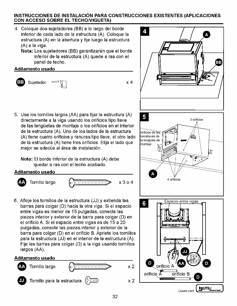
4. Coloque dos sujetadores (BB) a lo largo del borde inferior de cada lade de Ia estructura (A). Coloque Ia estructura (A) en Ia abertura y fije luego Ia estructura (A) a Ia viga. Nota: Los sujetadores (BB) garantizaran que el borde
inferior de Ia estructura (A) quede a ras con el panel de techo.
Aditamento usado
IJ Sujetador ~ x4
5. Use los tornillos largos (AA) para fijar Ia estructura (A) directamente a Ia viga usando los orificios tipo llave de las lenguetas de montaje o los orificios en el interior de Ia estructura (A). Uno de los Iadas de Ia estructura (A) tiene cuatro orificios y ranuras tipo llave, el otro lade de Ia estructura (A) tiene tres orificios. Elija el lade que mejor se adecue al area de instalaci6n.
Nota: El borde inferior de Ia estructura (A) debe quedar a ras con el techo acabado.
Aditamento usado
• Tornillo largo OD\Dll))) )))\)))))))) )))) D> x3o4
6. Afloje los tornillos de Ia estructura (JJ) y extienda las barras para colgar (D) hacia Ia otra viga. Si el espacio entre vigas es menor de 15 pulgadas, conecte las piezas interior y exterior de Ia barra para colgar (D) en el orificio A. Si el espacio entre vigas es de 15 a 20 pulgadas, conecte las piezas interior y exterior de Ia barra para colgar (D) en el orificio B. Apriete los tornillos para Ia estructura (JJ) en el interior de Ia estructura (A). Fije las barras para colgar (D) a Ia viga usando tornillos largos (AA).
Aditamento usado
Tornillo largo 01)))lll))l )))j)) )))))) ))))DJ> • • Tornillo para Ia estructura ®miD
x2
x2
32
• 4 orificios
A " v~
orificio A orificio B G) '--._ I • w • y
~ UTILITECH' ] Lowes.com l!l) -·-:
INSTRUCCIONES DE INSTALACION PARA CONSTRUCCIONES EXISTENTES (APLICACIONES CON ACCESO SOBRE EL TECHONIGUETA)
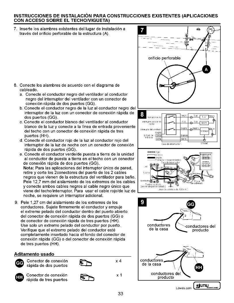
7. lnserte los alambres existentes del Iugar de instalaci6n a traves del orificio perforable de Ia estructura (A).
8. Conecte los alambres de acuerdo con el diagrama de cableado. a. Conecte el conductor negro del ventilador al conductor
negro del interruptor del ventilador con un conector de conexi6n rapida de dos puertos (GG).
orificio perforable
b. Conecte el conductor negro de Ia luz al conductor negro del :;;;;;;;;;;:=============================: interruptor de Ia luz con un conector de conexi6n rapida de dos puertos (GG).
c. Conecte el conductor blanco del ventilador al conductor blanco de Ia luz y conecte a Ia lfnea de entrada proveniente del techo con un conector de conexi6n rapida de tres puertos (HH).
d. Conecte el conductor rojo de Ia luz al conductor rojo del interruptor de Ia luz de noche con un conector de conexi6n rapida de dos puertos (GG).
e. Conecte el conductor verde/de puesta a tierra de Ia unidad al conductor de puesta a tierra en el techo con un conector
de conexi6n rapida de dos puertos (GG). Nota: Para las aplicaciones del interruptor unico de pared, retire y corte los 2conectores del puerto de los 2 cables negros que vienen de Ia estructura del ventilador para bano.
CaJa de interTuptor
r:zz;;:zzzz;z;m roj o c:::::::::J blanco
Luz
Pele 12,7 mm del aislamiento de los extremos de los cables venttlador Control multiple
y conecte ambos cables negros al cable negro unico que (se vende por separado)
viene del techo/interruptor. Para usar el cable rojo/de luz de L...-----L-ine_a_de_e_ntr-ad_a_de_12
_0v_A_c ______ __..
noche, se requiere un interruptor adicional.
9. Pele 1 ,27 em del aislamiento de los extremos de los conductores. Sujete firmemente el conductor y empuje el extremo pelado del conductor dentro del puerto abierto del conector de conexi6n rapida de dos puertos (GG) o de conector de conexi6n rapida de tres puertos (HH). Use solo un extremo pelado del conductor por puerto. Verifique que el extremo pelado del conductor este completamente insertado hacia el fondo del conector de conexi6n rapida (GG) o del conector de conexi6n rapida de tres puertos (H H).
Aditamento usado
Conector de conexi6n rapida de dos puertos
Conector de conexi6n rapida de tres puertos
x4
X 1
33
onductores del producto
~UTILITECH' J Lowes .com ~ -·-
INSTRUCCIONES DE INSTALACION PARA CONSTRUCCIONES EXISTENTES (APLICACIONES CON ACCESO SOBRE EL TECHONIGUETA)
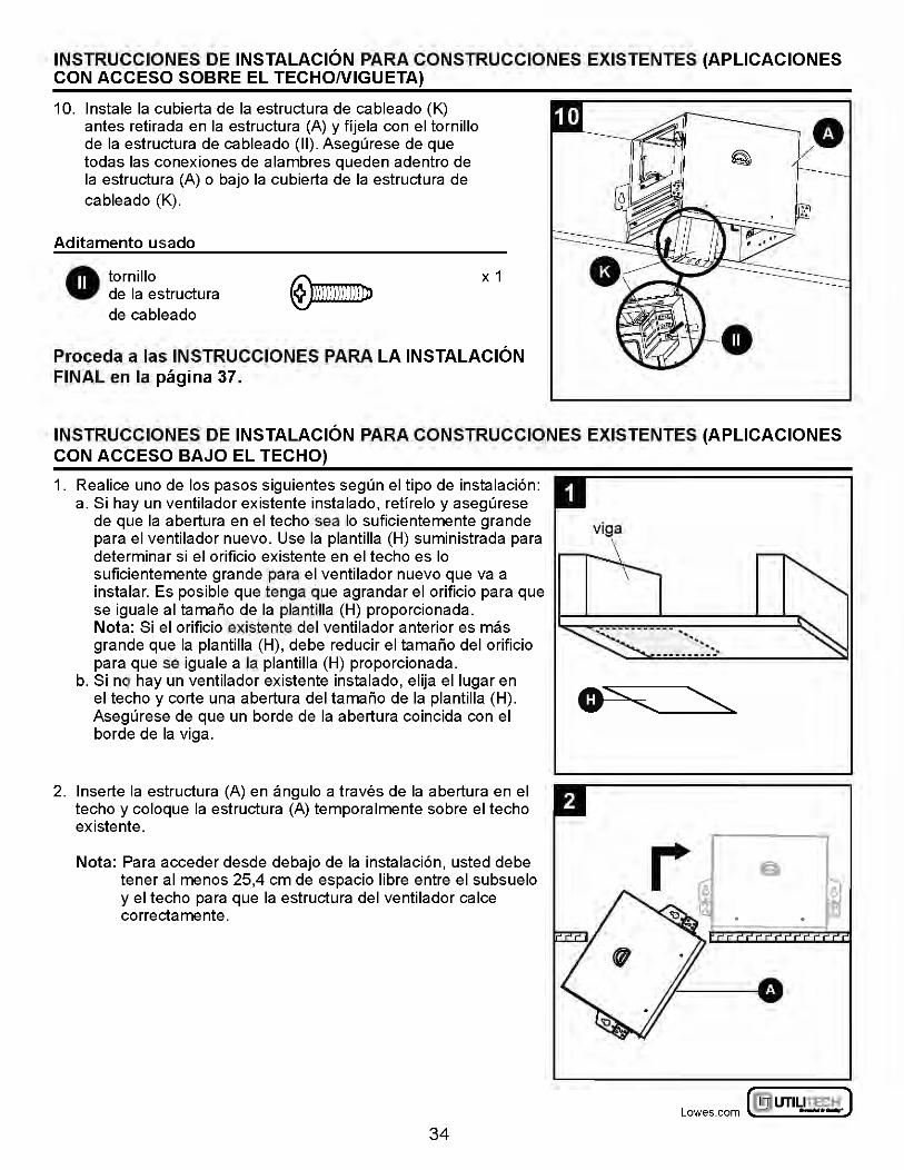
10. lnstale Ia cubierta de Ia estructura de cableado (K) antes retirada en Ia estructura (A) y ffjela con el tornillo de Ia estructura de cableado (II). Asegurese de que todas las conexiones de alambres queden adentro de Ia estructura (A) o bajo Ia cubierta de Ia estructura de cableado (K).
Aditamento usado
• tornillo de Ia estructura de cableado
X 1
Proceda a las INSTRUCCIONES PARA LA INSTALACION FINAL en Ia pagina 37.
INSTRUCCIONES DE INSTALACION PARA CONSTRUCCIONES EXISTENTES (APLICACIONES CON ACCESO BAJO EL TECHO)
1. Realice uno de los pasos siguientes segun el tipo de instalaci6n: a. Si hay un ventilador existente instalado, retfrelo y asegurese
de que Ia abertura en el techo sea lo suficientemente grande para el ventilador nuevo. Use Ia plantilla (H) suministrada para determinar si el orificio existente en el techo es lo suficientemente grande para el ventilador nuevo que va a instalar. Es posible que tenga que agrandar el orificio para que se iguale al tamario de Ia plantilla (H) proporcionada. Nota: Si el orificio existente del ventilador anterior es mas grande que Ia plantilla (H), debe reducir el tamario del orificio para que se iguale a Ia plantilla (H) proporcionada.
b. Si no hay un ventilador existente instalado, elija ellugar en el techo y corte una abertura del tamario de Ia plantilla (H). Asegurese de que un borde de Ia abertura coincida con el borde de Ia viga.
2. lnserte Ia estructura (A) en angulo a traves de Ia abertura en el techo y coloque Ia estructura (A) temporalmente sobre el techo existente.
Nota: Para acceder desde debajo de Ia instalaci6n, usted debe tener al menos 25,4 em de espacio libre entre el subsuelo y el techo para que Ia estructura del ventilador calce correctamente.
34
.. ... ________ ::~
~ UTILITECH' ] Lowes.com l!l) -·-:
INSTRUCCIONES DE INSTALACION PARA CONSTRUCCIONES EXISTENTES (APLICACIONES CON ACCESO BAJO EL TECHO)
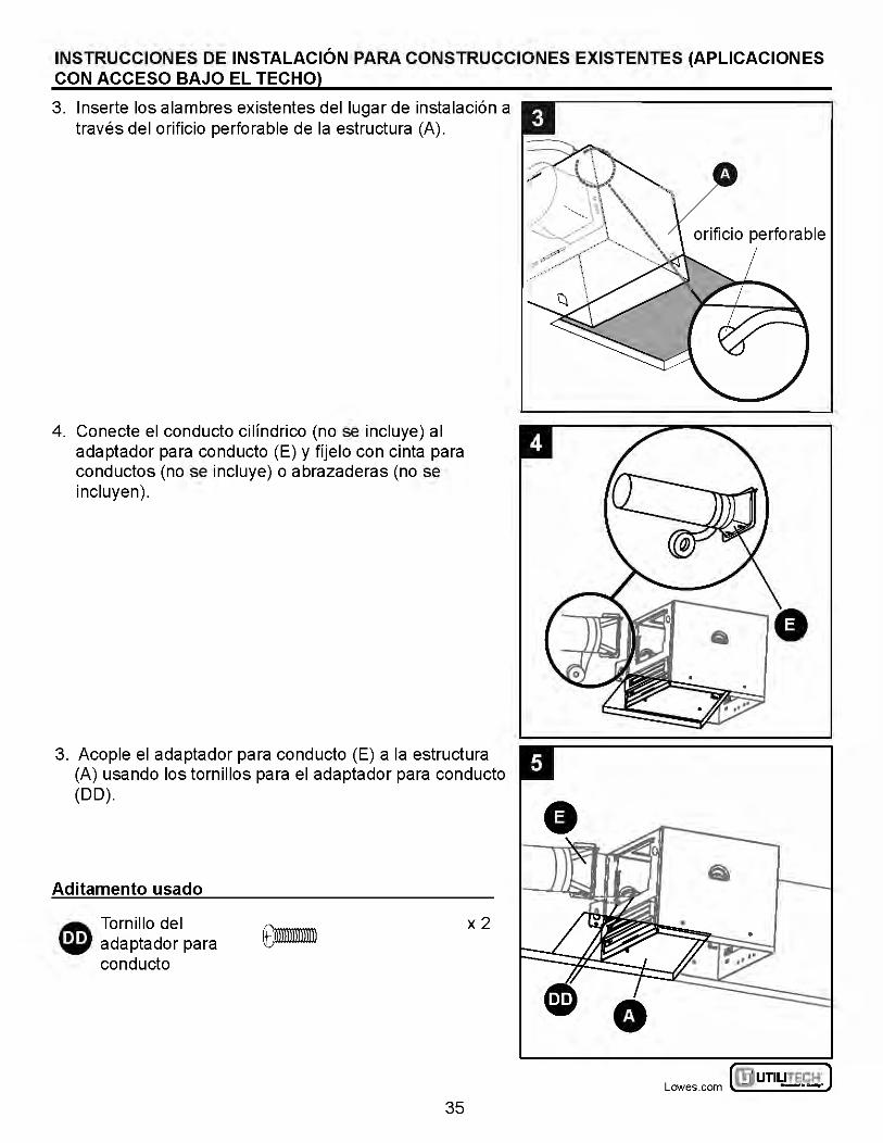
3. lnserte los alambres existentes del Iugar de instalaci6n a traves del orificio perforable de Ia estructura (A).
4. Conecte el conducto cilfndrico (nose incluye) al adaptador para conducto (E) y ffjelo con cinta para conductos (no se incluye) o abrazaderas (no se incluyen).
3. Acople el adaptador para conducto (E) a Ia estructura (A) usando los tornillos para el adaptador para conducto (DD).
Aditamento usado
~ Tornillo del W adaptador para
conducto
x2
35
~UTILITECH" J Lowes .com ~ -·-
INSTRUCCIONES DE INSTALACION PARA CONSTRUCCIONES EXISTENTES (APLICACIONES CON ACCESO BAJO EL TECHO)
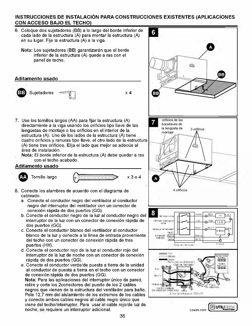
6. Coloque dos sujetadores (BB) a lo largo del borde inferior de cada lado de Ia estructura (A) para montar Ia estructura (A) en su Iugar. Fije Ia estructura (A) a Ia viga.
Nota: Los sujetadores (BB) garantizaran que el borde inferior de Ia estructura (A) quede a ras con el panel de techo.
Aditamento usado
ID Sujetadores ~ x4
7. Use los tornillos largos (AA) para fijar Ia estructura (A) directamente a Ia viga usando los orificios tipo llave de las lengUetas de montaje o los orificios en el interior de Ia estructura (A). Uno de los lados de Ia estructura (A) tiene cuatro orificios y ranuras tipo llave, el otro lado de Ia estructura (A) tiene tres orificios. Elija ellado que mejor se adecue al area de instalaci6n. Nota: El borde inferior de Ia estructura (A) debe quedar a ras
con el techo acabado. Aditamento usado
• Tornillo largo ODJ))j)))j)))j))) I )))jl ))[Dl> x3o4
8. Conecte los alambres de acuerdo con el diagrama de cableado. a. Conecte el conductor negro del ventilador al conductor
negro del interruptor del ventilador con un conector de conexi6n rap ida de dos puertos (GG).
b. Conecte el conductor negro de Ia luz al conductor negro del interruptor de Ia luz con un conector de conexi6n rapida de dos puertos (GG).
c. Conecte el conductor blanco del ventilador al conductor blanco de Ia luz y conecte a Ia lfnea de entrada proveniente del techo con un conector de conexi6n rapida de tres puertos (HH).
d. Conecte el conductor rojo de Ia luz al conductor rojo del interruptor de Ia luz de noche con un conector de conexi6n rapida de dos puertos (GG).
e. Conecte el conductor verde/de puesta a tierra de Ia unidad al conductor de puesta a tierra en el techo con un conector de conexi6n rapida de dos puertos (GG). Nota: Para las aplicaciones del interruptor unico de pared, retire y corte los 2conectores del puerto de los 2 cables negros que vienen de Ia estructura del ventilador para bario. Pele 12,7 mm del aislamiento de los extremos de los cables y conecte ambos cables negros al cable negro unico que viene del techo/ interruptor. Para usar el cable rojo/de luz de noche, se requiere un interruptor adicional.
36
orificios de las bocallaves de
4 orificios
Ca;a de mterruptor
~roJO
=blanco
Luz
Venti! ad or
Control multiple (se vende por separado)
Linea de entrada de 120V AC
Unidad
~ UTILITECH' ] Lowes.com l!l) -·-:
INSTRUCCIONES DE INSTALACION PARA CONSTRUCCIONES EXISTENTES (APLICACIONES CON ACCESO BAJO EL TECHO)
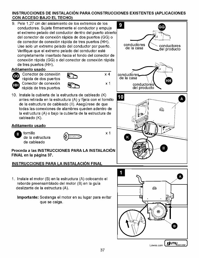
9. Pele 1 ,27 em del aislamiento de los extremes de los conductores. Sujete firmemente el conductor y empuje el extrema pelado del conductor dentro del puerto abierto del co nectar de conexi6n rapida de dos puertos (GG) o de conector de conexi6n rapida de tres puertos (HH). Use solo un extrema pelado del conductor par puerto. Verifique que el extrema pelado del conductor este completamente insertado hacia el fonda del conector de conexi6n rapida (GG) o del co nectar de conexi6n rapida de tres puertos (HH).
Aditamento usado
• Conector de conexi6n ~
~ rapida de dos puertos ~ Co nectar de conexi6n .., rapida de tres puertos
x4
X 1
10. In stale Ia cubierta de Ia estructura de cableado (K) antes retirada en Ia estructura (A) y fljela con el tornillo de Ia estructura de cableado (II). Asegurese de que todas las conexiones de alambres queden adentro de Ia estructura (A) o bajo Ia cubierta de Ia estructura de cableado (K).
Aditamento usado
• tornillo de Ia estructura de cableado
X 1
Proceda a las INSTRUCCIONES PARA LA INSTALACION FINAL en Ia pagina 37.
INSTRUCCIONES PARA LA INSTALACION FINAL
1. lnstale el motor (B) en Ia estructura (A) colocando el reborde preensamblado del motor (B) en Ia gula
deslizante de Ia estructura (A).
lmportante: Sostenga el motor en su Iugar para evitar que se caiga.
37
~UTILITECH' J Lowes .com ~ -·-
INSTRUCCIONES PARA LA INSTALACION FINAL
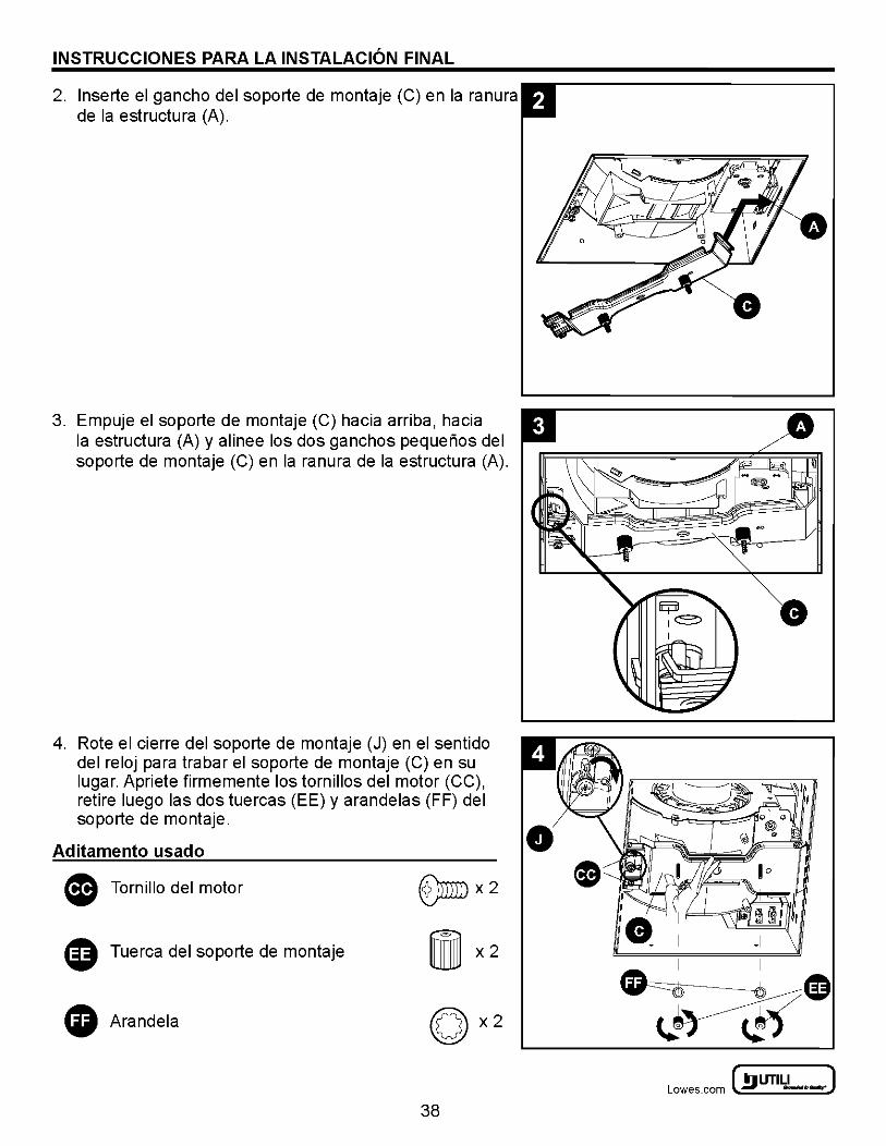
2. lnserte el gancho del soporte de montaje (C) en Ia ranura de Ia estructura (A).
3. Empuje el soporte de montaje (C) hacia arriba, hacia Ia estructura (A) y alinee los dos ganchos pequerios del soporte de montaje (C) en Ia ranura de Ia estructura (A).
4. Rote el cierre del soporte de montaje (J) en el sentido del reloj para trabar el soporte de montaje (C) en su Iugar. Apriete firmemente los tornillos del motor (CC), retire luego las dos tuercas (EE) y arandelas (FF) del soporte de montaje.
Aditamento usado
G Tornillo del motor ®mmx2
0 Tuerca del soporte de montaje
G Arandela
38
0
~ UTILITECH' ] Lowes.com l!l) -·-:
INSTRUCCIONES PARA LA INSTALACION FINAL
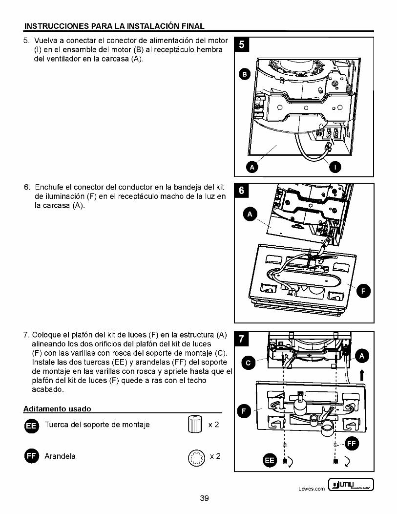
5. Vuelva a conectar el co nectar de alimentaci6n del motor (I) en el ensamble del motor (B) al receptacula hembra del ventilador en Ia carcasa (A).
6. Enchufe el conector del conductor en Ia bandeja del kit de iluminaci6n (F) en el receptacula macho de Ia luz en Ia carcasa (A).
7. Coloque el plaf6n del kit de luces (F) en Ia estructura (A) alineando los dos orificios del plaf6n del kit de luces (F) con las varillas con rosca del soporte de montaje (C). lnstale las dos tuercas (EE) y arandelas (FF) del soporte 8 de montaje en las varillas con rosca y apriete hasta que el plaf6n del kit de luces (F) quede a ras con el techo acabado.
Aditamento usado 0 G) Tuerca del soporte de montaje
0 Arandela
39
I
tl )
~UTILITECH" J Lowes .com ~ -·-
INSTRUCCIONES PARA LA INSTALACION FINAL
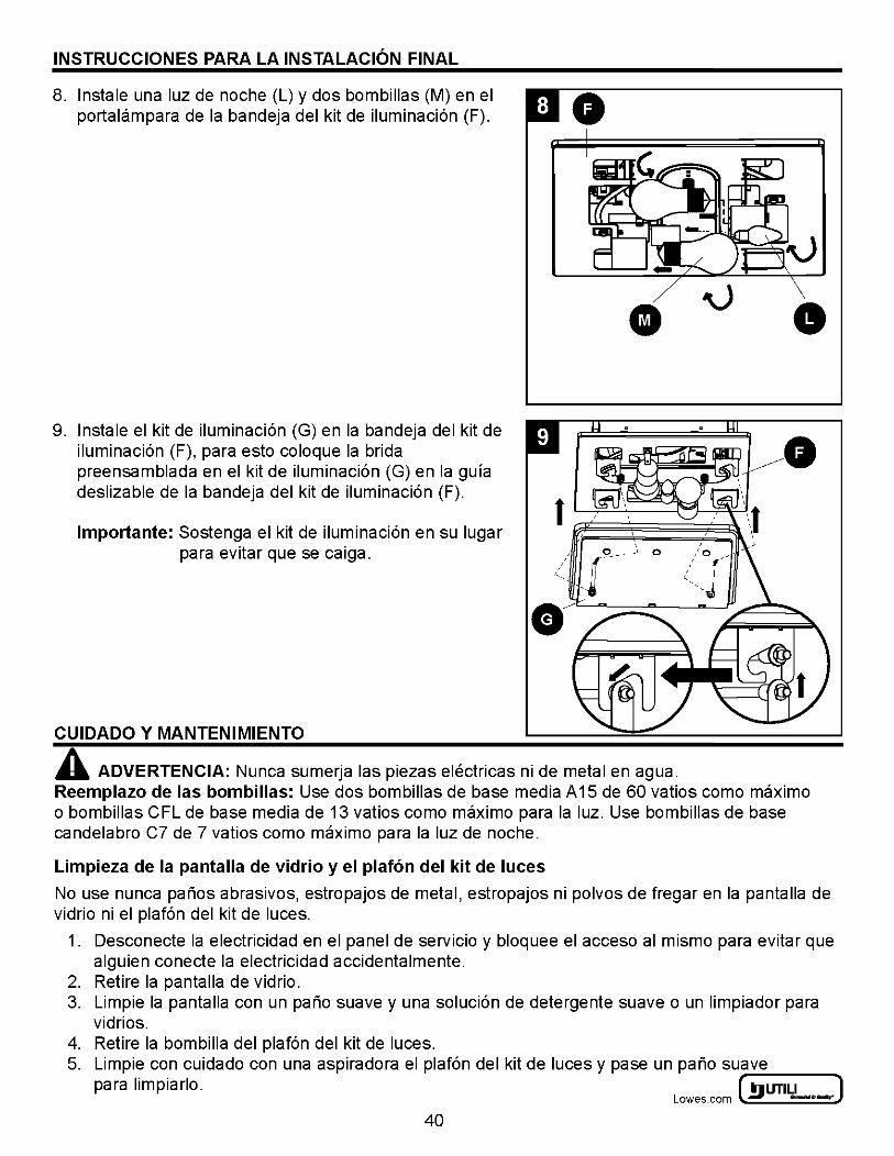
8. lnstale una luz de noche (L) y dos bombillas (M) en el 0 portalampara de Ia bandeja del kit de iluminaci6n (F).
9. lnstale el kit de iluminaci6n (G) en Ia bandeja del kit de iluminaci6n (F), para esto coloque Ia brida preensamblada en el kit de iluminaci6n (G) en Ia gula deslizable de Ia bandeja del kit de iluminaci6n (F).
lmportante: Sostenga el kit de iluminaci6n en su Iugar para evitar que se caiga.
CUIDADO Y MANTENIMIENTO
•
t ~-----~.-~~ / _1
c ____ O c
A ADVERTENCIA: Nunca sumerja las piezas electricas ni de metal en agua.
0
Reemplazo de las bombillas: Use dos bombillas de base media A 15 de 60 vatios como maximo o bombillas CFL de base media de 13 vatios como maximo para Ia luz. Use bombillas de base candelabra C7 de 7 vatios como maximo para Ia luz de noche.
Limpieza de Ia pantalla de vidrio y el plaf6n del kit de luces
No use nunca parios abrasives, estropajos de metal, estropajos ni polvos de fregar en Ia pantalla de vidrio ni el plaf6n del kit de luces.
1. Desconecte Ia electricidad en el panel de servicio y bloquee el acceso al mismo para evitar que alguien conecte Ia electricidad accidentalmente.
2. Retire Ia pantalla de vidrio. 3. Limpie Ia pantalla con un pario suave y una soluci6n de detergente suave o un limpiador para
vidrios. 4. Retire Ia bombilla del plaf6n del kit de luces. 5. Limpie con cuidado con una aspiradora el plaf6n del kit de luces y pase un pario suave
para lim pia rio. ~~ffi~ur-I_LI_TE_C_H ....... ] Lowes.com ~ -·-.
40
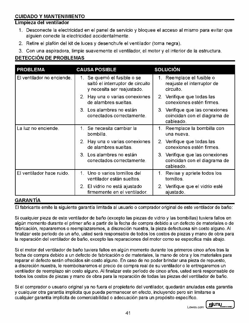
CUIDADO Y MANTENIMIENTO Limpieza del ventilador
1. Desconecte Ia electricidad en el panel de servicio y bloquee el acceso al mismo para evitar que alguien conecte Ia electricidad accidentalmente.
2. Retire el plaf6n del kit de luces y desenchufe el ventilador (toma negra).
3. Con una aspiradora, limpie suave mente el ventilador, el motor y el interior de Ia estructura.
DETECCION DE PROBLEMAS
PROBLEMA CAUSA POSIBLE SOLUCION
El ventilador no enciende. 1. Se quem6 el fusible o se 1. Reemplace el fusible o salt6 el interrupter de circuito reajuste el interrupter de y necesita ser reajustado. circuito.
2. Hay una o varias conexiones 2. Verifique que todas las de alambres sueltas. conexiones esten firmes.
3. Los alambres no estan 3. Verifique que las conexiones conectados correctamente. coincidan con el diagrama de
cableado.
La luz no enciende. 1. Se necesita cambiar Ia 1. Reemplace Ia bombilla con bombilla. una nueva.
2. Hay una o varias conexiones 2. Verifique que todas las de alambres sueltas. conexiones esten firmes.
3. Los alambres no estan 3. Verifique que las conexiones conectados correctamente. coincidan con el diagrama de
cableado.
El ventilador hace ruido. 1. Uno o varios tornillos del 1. Revise y apriete todos los ventilador estan sueltos. tornillos.
2. El vidrio no esta ajustado 2. Verifique que el vidrio este firmemente en el ventilador. ajustado.
GARANTiA El fabricante emite Ia siguiente garantfa limitada al usuario o comprador original de este ventilador de bario:
Si cualquier pieza de este ventilador de bario (excepto las piezas de vidrio y las bombillas) tuviera fallos en algun momenta durante el primer aria a partir de Ia fecha de compra debido a un defecto de materiales o de fabricaci6n, repararemos o reemplazaremos, a discreci6n nuestra, Ia pieza defectuosa sin costa alguno. AI finalizar este perfodo de un aria, usted sera responsable de todos los costas de piezas y mana de obra para Ia reparaci6n del ventilador de bario, excepto las reparaciones del motor como se especifica mas abajo.
Si el motor del ventilador de bario tuviera fallos en algun momenta durante los primeros cinco alios tras Ia fecha de compra debido a un defecto de fabricaci6n o de materiales, Ia mana de obra y los materiales para reparar el defecto seran ofrecidos sin costa alguno. En caso de no poder brindar una pieza de repuesto, a discreci6n nuestra, le reembolsaremos el precio de compra real de su ventilador o le entregaremos un ventilador de reemplazo sin costa alguno. AI finalizar este perfodo de cinco alios, usted sera responsable de todos los costas de piezas y mana de obra para Ia reparaci6n de todas las piezas del ventilador de bario.
Si el comprador o usuario original ya no fuera el propietario del ventilador, quedaran anuladas esta garantfa y cualquier otra garantfa implfcita que pueda permanecer en efecto, incluyendo pero sin limitarse a cualquier garantfa implfcita de comerciabilidad o adecuaci6n para un prop6sito especffico.
~UTILITECH" J Lowes .com ~ -·-
41
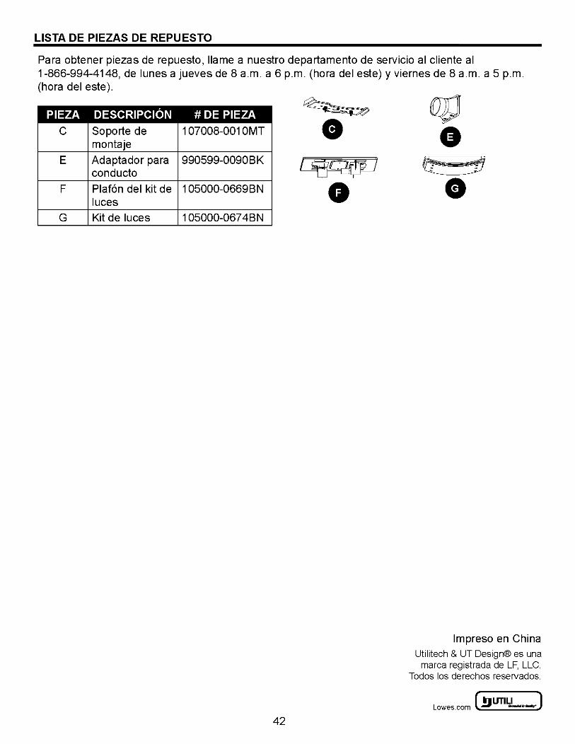
LIST A DE PIEZAS DE REPU ESTO
Para obtener piezas de repuesto, llame a nuestro departamento de servicio al cliente al 1-866-994-4148, de lunes a jueves de 8 a.m. a 6 p.m. (hora del este) y viernes de 8 a.m. a 5 p.m. (hora del este ).
PIEZA DESCRIPCION
c Soporte de montaje
E Adaptador para conducto
F Plaf6n del kit de luces
G Kit de luces
#DE PIEZA
1 07008-001 OMT
990599-0090BK
1 05000-0669BN
1 05000-067 4BN
42
lmpreso en China Utilitech & UT Design® es una
marca registrada de LF, LLC. Todos los derechos reservados.
~ UTILITECH' ] Lowes.com l!l) -·-:
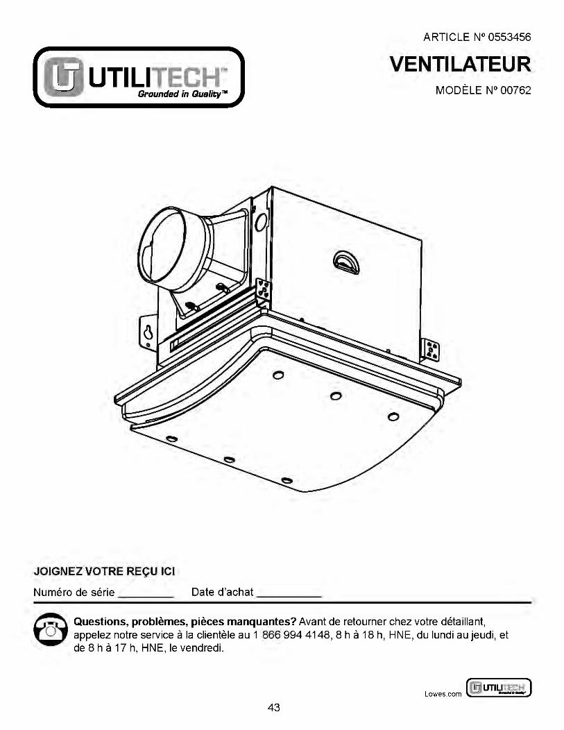
ARTICLE N° 0553456
Grounded in Quality""
VENTILATEUR UTILITECHlM MODELE N° 00762
JOIGNEZ VOTRE RECU ICI
Numero de serie Date d'achat
~ Questions, problemes, pieces manquantes? Avant de retourner chez votre detaillant, ~ appelez notre service a Ia clientele au 1 866 994 4148, 8 h a 18 h, HNE, du lundi au jeudi, et
de 8 h a 17 h, HNE, le vendredi.
~ UTILITECH' ] Lowes.com l!l) -·-:
43
TABLE DES MATII~RES
Contenu de Ia bol'te ............................................................ 49
Materiel ..................................................................... 50
Renseignements sur Ia securite ................................................... 51
Preparation ................................................................... 52
Instructions d'installation initiale ................................................... 52
Instructions d'installation sur un nouvel element de construction ......................... 53
Instructions pour !'installation dans le cadre d'une construction existante (solivelinstallation au plafond avec acces par le haut) ................................................... 56
Instructions pour !'installation dans le cadre d'une construction existante (installation au plafond avec acces par le bas) .......................................................... 61
Instructions d'installation finale ................................................... 64
Nettoyage et entretien .......................................................... 67
Depannage ................................................................... 68
Garantie ..................................................................... 68
Liste des pieces de rechange .. . .. . ............... . .. . ............... . .. . .. . ..... 69
~UTILITECH" J Lowes .com ~ -·-
44
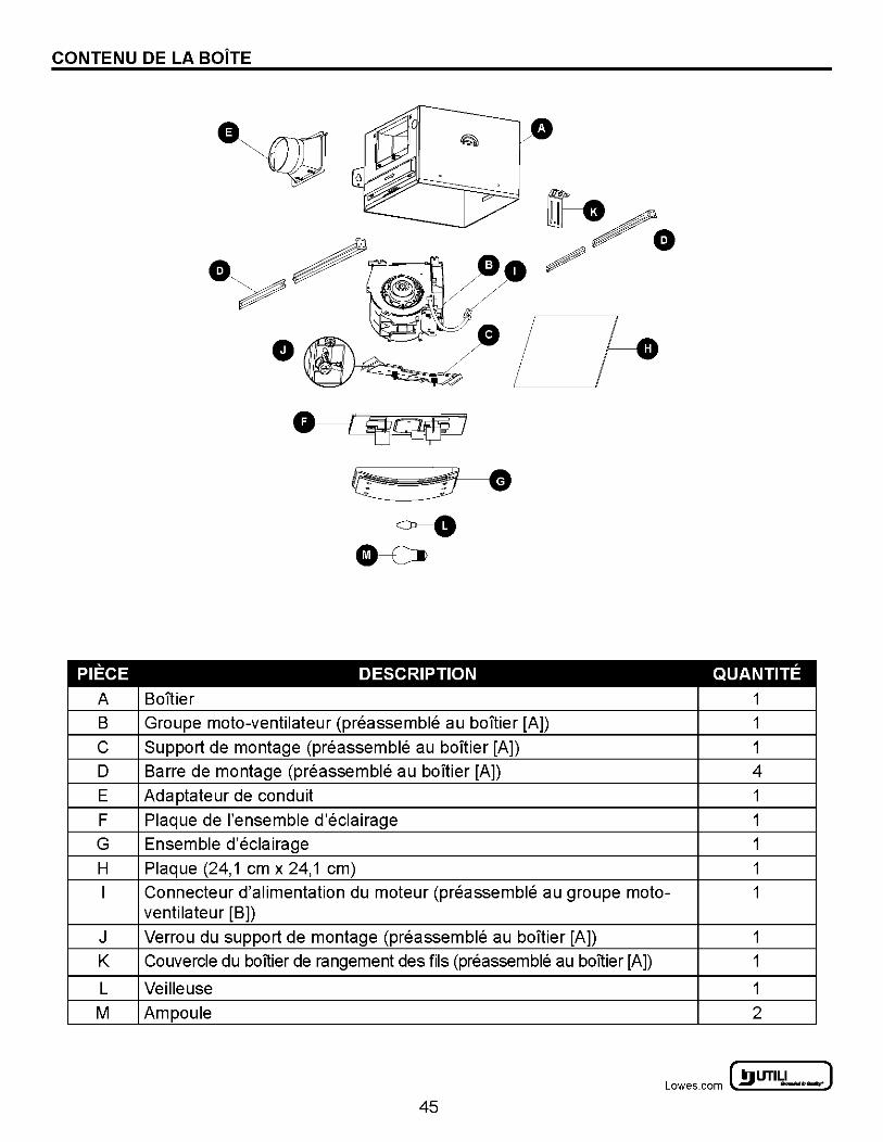
CONTENU DE LA BOiTE
PIECE
A
B
c D
E
F
G
H
I
J K
L
M
Bol'tier
·~ ~· ~
8----Ca
DESCRIPTION
Groupe moto-ventilateur (preassemble au baTtier [A])
Support de montage (preassemble au boitier [A])
Barre de montage (preassemble au boltier [A])
Adaptateur de conduit
Plaque de !'ensemble d'eclairage
Ensemble d'eclairage
Plaque (24, 1 em x 24,1 em)
QUANTITE
1
1
1
4
1
1
1
1
Connecteur d'alimentation du moteur (preassemble au groupe moto- 1 ventilateur [B])
Verrou du support de montage (preassemble au bonier [A]) 1
Couvercle du boltier de rangement des fils (preassemble au boltier [A]) 1
Veilleuse 1
Ampoule 2
~ UTILITECH' ] Lowes.com l!l) -·-:
45
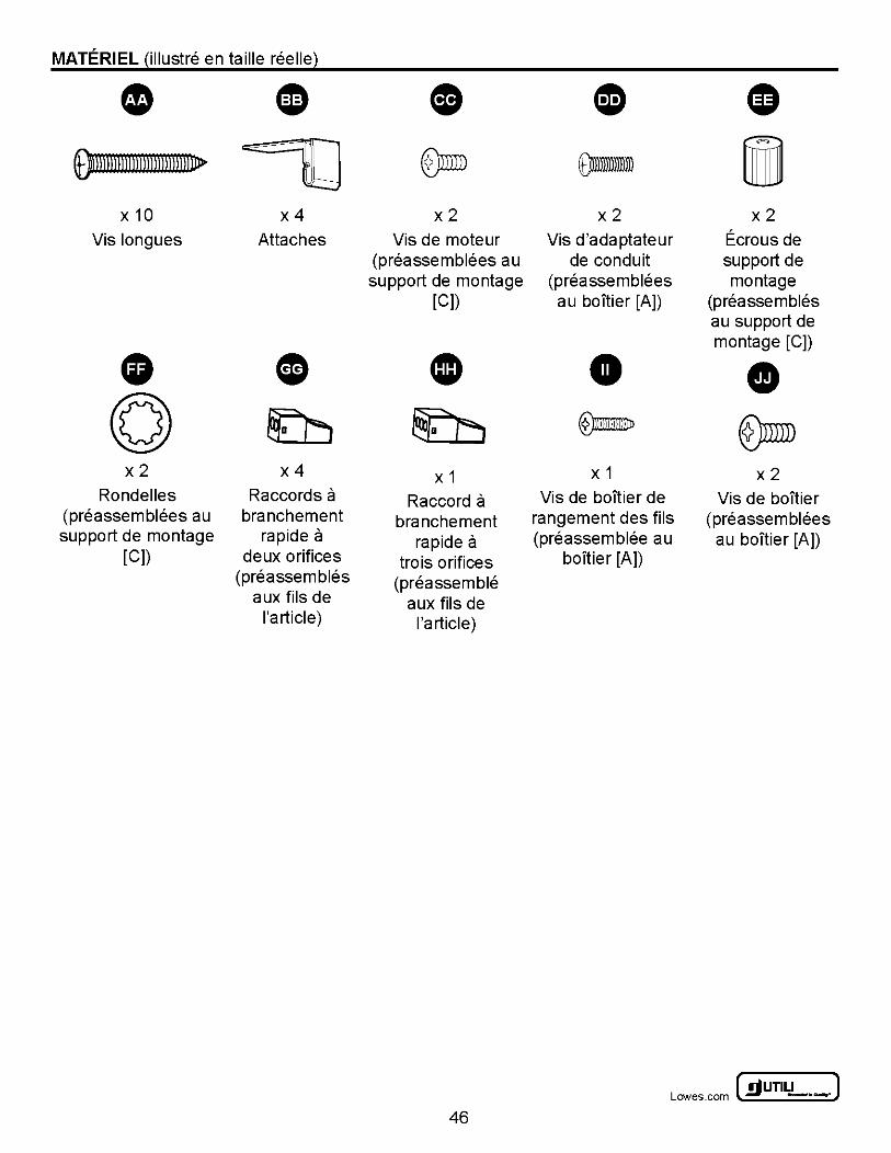
MATERIEL Qllustre en taille reellel
• ~ - 0 CD G 9mmll n nnnnl 1 rum 11> ~ ~ om- i
x10 x4 x2 x2 x2
Vis longues Attaches Vis de moteur Vis d'adaptateur Ecrous de (preassemblees au de conduit support de support de montage (pre a sse mblees montage
[C]) au boltier [A]) (preassembles au support de montage [C])
• • CD • • (Q) ~ ~ ®a- ®mm x2 x4 X 1 X 1 x2
Rondelles Raccords a Raccord a Vis de boltier de Vis de boltier (preassemblees au branchement branchement rangement des fils (preassemblees support de montage rapide a rapide a (preassemblee au au boltier [A])
[C]) deux orifices trois orifices boltier [A]) (preassembles (preassemble
aux fils de aux fils de !'article) !'article)
~UTILITECH" J Lowes .com ~ -·-
46
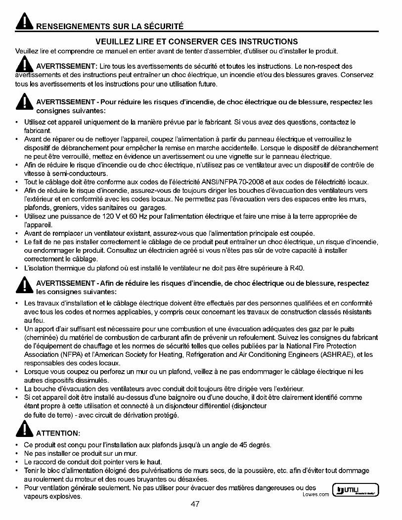
A RENSEIGNEMENTS SUR LA SECURITE
VEUILLEZ LIRE ET CONSERVER CES INSTRUCTIONS Veuillez lire et comprendre ce manuel en entier avant de tenter d'assembler, d'utiliser ou d'installer le produit.
A AVERTISSEMENT: Lire to us les avertissements de securite et toutes les instructions. Le non-respect des Ssements et des instructions peut entrainer un choc electrique, un incendie et'ou des blessures graves. Conservez
tousles avertissements et les instructions pour une utilisation future.
A AVERTISSEMENT- Pour n§duire les risques d'incendie, de choc electrique ou de blessure, respectez les consignes suivantes:
• Utilisez cet appareil uniquement de Ia maniere prevue par le fabricant. Si vous avez des questions, contactez le fabricant.
• Avant de reparer ou de nettoyer l'appareil, coupez !'alimentation a partir du panneau electrique et verrouillez le dispositif de debranchement pour empEkher Ia remise en marche accidentelle. Lorsque le dispositif de debranchement ne peut etre verrouille, mettez en evidence un avertissement ou une vignette sur le panneau electrique.
• Afin de reduire le risque d'incendie ou de choc electrique, n'utilisez pas ce ventilateur avec un dispositif de contr61e de vitesse a semi-conducteurs.
• Toutle cablage doit etre conforme aux codes de l'electricite ANSI/NFPA 70-2008 et aux codes de l'electricite locaux. • Afin de reduire le risque d'incendie, assurez-vous de toujours diriger les bouches d'evacuation des ventilateurs vers
l'exterieur et en conformite avec les codes locaux. Ne permettez pas !'evacuation vers des espaces entre les murs, plafonds, greniers, vides sanitaires ou garages.
• Utilisez une puissance de 120 Vet 60 Hz pour I' alimentation electrique et faire une mise a Ia terre appropriee de l'appareil.
• Avant de remplacer un ventilateur existant, assurez-vous que !'alimentation principale est coupee. • Le fait de ne pas installer correctement le cablage de ce produit peut entrainer un choc electrique, un risque d'incendie,
ou endommager le produit. Consultez un electricien agree si vous n'etes pas sur de votre capacite a installer correctement le cablage.
• L'isolation thermique du plafond ouest installe le ventilateur ne doit pas etre superieure a R40.
A AVERTISSEMENT -Afin de reduire les risques d'incendie, de choc electrique ou de blessure, respectez .. les consignes suivantes:
• Les travaux d'installation et le cablage electrique doivent etre effectues par des personnes qualifiees et en conformite avec tousles codes et normes applicables, y compris ceux concernant les travaux de construction classes resistants au feu.
• Un apport d'air suffisant est necessaire pour une combustion et une evacuation adequates des gaz par le puits (cheminee) du materiel de combustion de carburant afin de prevenir un refoulement. Suivez les consignes du fabricant de l'equipement de chauffage et les normes de securite telles que celles publiees par Ia National Fire Protection Association (NFPA) et !'American Society for Heating, Refrigeration and Air Conditioning Engineers (ASH RAE), et les responsables des codes locaux.
• Lorsque vous coupez ou perforez un mur ou un plafond, veillez a ne pas endommager le cablage electrique niles autres dispositifs dissimules.
• La bouche d'evacuation des ventilateurs avec conduit do it toujours etre dirigee vers l'exterieur. • Si cet appareil doit etre installe au-dessus d'une baignoire ou d'une douche, il doit etre clairement identifie comme
etant pro pre a cette utilisation et connecte a un disjoncteur differentiel (disjoncteur de fuite de terre)- avec circuit de derivation protege.
A ATTENTION:
• Ce produit est con9u pour !'installation aux plafonds jusqu'a un angle de 45 degres. • Ne pas installer ce produit sur un mur. • Le raccord de conduit doit pointer vers le haut. • Tenir le bloc d'alimentation eloigne des pulverisations de murs sees, de Ia poussiere, etc. a fin d'eviter tout dommage
au roulement du moteur et des roues bruyantes ou desaxees. • Pour ventilation generale seulement. Ne pas utiliser pour evacuer des matieres dangereuses ou des ( ffi UTILITECH' )
vapeurs explosives. Lowes.com . -·-.
47
PREPARATION
Avant de commencer !'assemblage du produit, s'assurer que toutes les pieces sont incluses. Comparer les pieces avec Ia liste de materiel incluse dans l'emballage. Ne pas tenter d'assembler le produit si une piece est manquante ou endommagee.
Temps d'installation estime: 30 a 60 minutes
Outils requis pour !'assemblage (non inclus): tournevis a tete cruciforme, marteau, claus, ruban adhesif, scie, ruban a mesurer, crayon, regie
INSTRUCTIONS D'INSTALLATION INITIALE
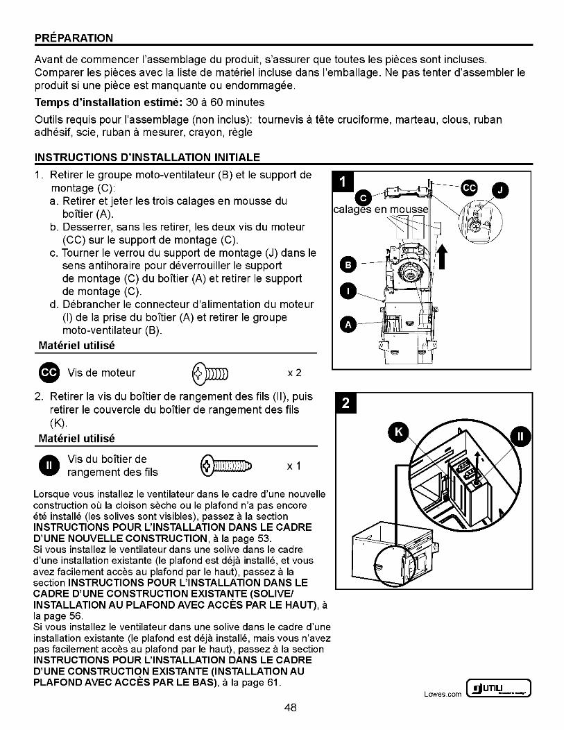
1. Retirer le groupe moto-ventilateur (B) et le support de montage (C): a. Retirer et jeter les trois calages en mousse du
boitier (A). b. Desserrer, sans les retirer, les deux vis du moteur
(CC) sur le support de montage (C). c. Tourner le verrou du support de montage (J) dans le
sens antihoraire pour deverrouiller le support 0 de montage (C) du boltier (A) et retirer le support O de montage (C).
d. Debrancher le connecteur d'alimentation du moteur (I) de Ia prise du boltier (A) et retirer le groupe moto-ventilateur (B).
Materiel utilise
(I Vis de moteur @IDm x 2
2. Retirer Ia vis du boltier de rangement des fils (II), puis retirer le couvercle du bonier de rangement des fils (K).
Materiel utilise
• Vis du boltier de rangement des fils
X 1
Lorsque vous installez le ventilateur dans le cadre d'une nouvelle construction ou Ia cloison seche ou le plafond n'a pas encore ete installe (les solives sont visibles), passez a Ia section INSTRUCTIONS POUR L'INSTALLATION DANS LE CADRE D'UNE NOUVELLE CONSTRUCTION, a Ia page 53. Si vous installez le ventilateur dans une solive dans le cadre d'une installation existante (le plafond est deja installe, et vous avez facilement acces au plafond par le haut), passez a Ia section INSTRUCTIONS POUR L'INSTALLATION DANS LE CADRE D'UNE CONSTRUCTION EXISTANTE (SOLIVE/ INSTALLATION AU PLAFOND AVEC ACCES PARLE HAUT), a Ia page 56. Si vous installez le ventilateur dans une solive dans le cadre d'une installation existante (le plafond est deja installe, mais vous n'avez pas facilement acces au plafond par le haut), passez a Ia section INSTRUCTIONS POUR L'INSTALLATION DANS LE CADRE D'UNE CONSTRUCTION EXISTANTE (INSTALLATION AU PLAFOND AVEC ACCES PARLE BAS), a Ia page 61.
48
~UTILITECH" J Lowes .com ~ -·-

INSTRUCTIONS D'INSTALLATION SUR UN NOUVEL ELEMENT DE CONSTRUCTION
1. Utiliser les vis longues (AA) pour visser directement le boltier a Ia poutre en utilisant les trous des pattes de fixation ou les trous a l'interieur du boltier (A). L'un des cotes du boltier possede quatre trous et des fentes de montage, tandis que l'autre cote du boltier dispose de trois trous. Choisissez le cote le mieux adapte au lieu d 'installation.
Remarque: Le bard inferieur du boltier (A) doit etre a niveau avec le plafond fini.
Materiel utilise
• Vis longues ~\D)))ll))l\ll))l\ll)II)))\}Jl> x 3 or 4
2. Desserrer les vis de boltier (JJ) et etendre les barres de montage (D) a Ia poutre.
Materiel utilise
• Vis de boltier @)miD x2
3. Si l'espace entre les poutres est inferieur a 38 em, relier les pieces a l'interieur et a l'exterieur de Ia barre de montage (D) au trou A. Si l'espace entre les poutres est de 38 em a 51 em, relier les pieces a l'interieur eta l'exterieur de Ia barre de montage (D) au trou B. Serrer les vis de boltier (JJ) a l'interieur du boltier (A). Fixer les barres de montage (D) a Ia poutre a l'aide des vis longues (AA).
Materiel utilise
• Vis longues ~))lll)\1)\))\))\ll))lll]lJIDJ> x2
fl Vis de boltier x2
49
4 trous
D r- r-espace entre les poutres
0 II =::::::)
c: :l. - - ..... T
"" - . ~\·. -
• '-- '--
espace entre les poutres
~A' trou A ·IIE==:;:::tr:::Jou B A ~~~~~~/ ===:::::::Jr-0
~ UTILITECH' ] Lowes.com l!l) -·-:
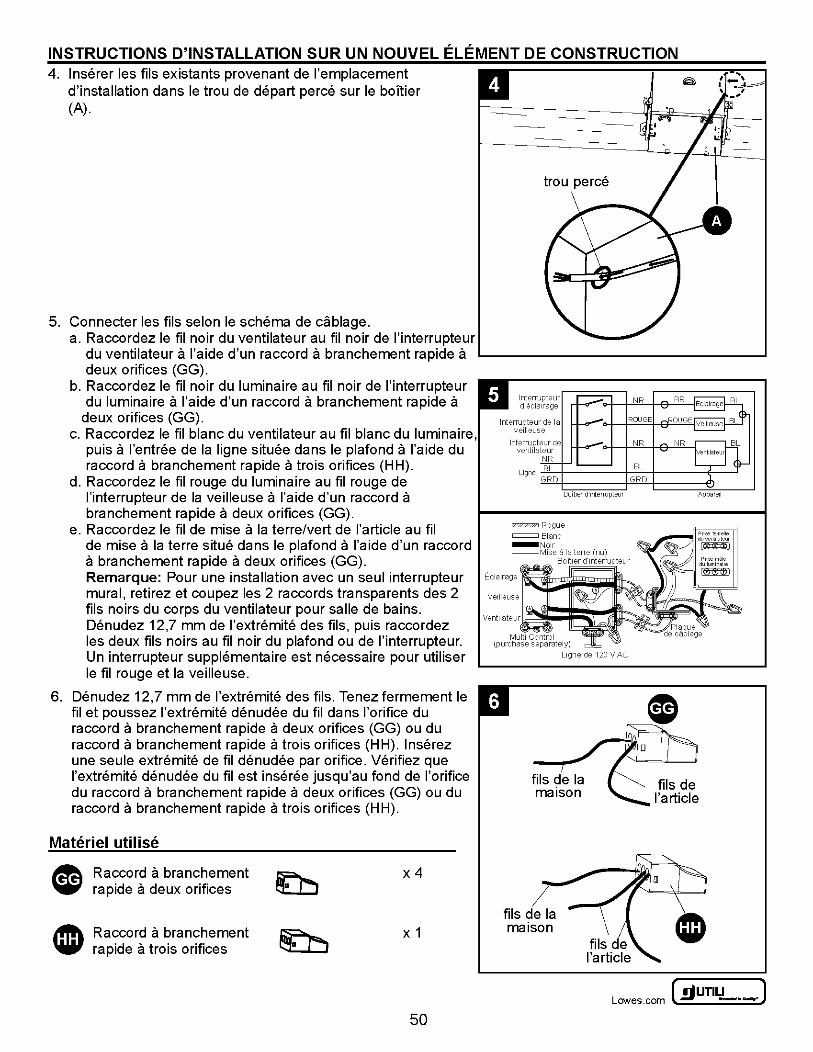
INSTRUCTIONS D'INSTALLATION SUR UN NOUVEL ELEMENT DE CONSTRUCTION 4. lnserer les fils existants provenant de !'emplacement
d'installation dans le trou de depart perce sur le boTtier (A).
5. Connecter les fils selon le schema de cablage. a. Raccordez le fil noir du ventilateur au fil noir de l'interrupteur
du ventilateur a l'aide d'un raccord a branchement rapide a deux orifices (GG).
b. Raccordez le fil noir du luminaire au fil noir de l'interrupteur du luminaire a l'aide d'un raccord a branchement rapide a
deux orifices (GG). c. Raccordez le fil blanc du ventilateur au fil blanc du luminaire,
puis a l'entree de Ia ligne situee dans le plafond a l'aide du raccord a branchement rapide a trois orifices (HH).
d. Raccordez le fil rouge du luminaire au fil rouge de l'interrupteur de Ia veilleuse a l'aide d'un raccord a branchement rapide a deux orifices (GG).
e. Raccordez le fil de mise a Ia terre/vert de !'article au fil de mise a Ia terre situe dans le plafond a l'aide d'un raccord a branchement rapide a deux orifices (GG). Remarque: Pour une installation avec un seul interrupteur mural, retirez et coupez les 2 raccords transparents des 2 fils noirs du corps du ventilateur pour salle de bains. Denudez 12,7 mm de l'extremite des fils, puis raccordez les deux fils noirs au fil noir du plafond ou de l'interrupteur. Un interrupteur supplementaire est necessaire pour utiliser le fil rouge et Ia veilleuse.
6. Denudez 12,7 mm de l'extremite des fils. Tenez fermement le fil et poussez l'extremite denudee du fil dans !'orifice du raccord a branchement rapide a deux orifices (GG) ou du raccord a branchement rapide a trois orifices (HH). lnserez une seule extremite de fil denudee par orifice. Verifiez que l'extremite denudee du fil est inseree jusqu'au fond de !'orifice du raccord a branchement rapide a deux orifices (GG) ou du raccord a branchement rapide a trois orifices (HH).
Materiel utilise
Raccord a branchement rapide a deux orifices
Raccord a branchement rapide a trois orifices
x4
X 1
50
trou perce
=Rogue = Blanc
Multi Control (purchase separately)
Llgne de 120 V AC
maison
maison
~UTILITECH" J Lowes .com ~ -·-
INSTRUCTIONS D'INSTALLATION SUR UN NOUVEL ELEMENT DE CONSTRUCTION
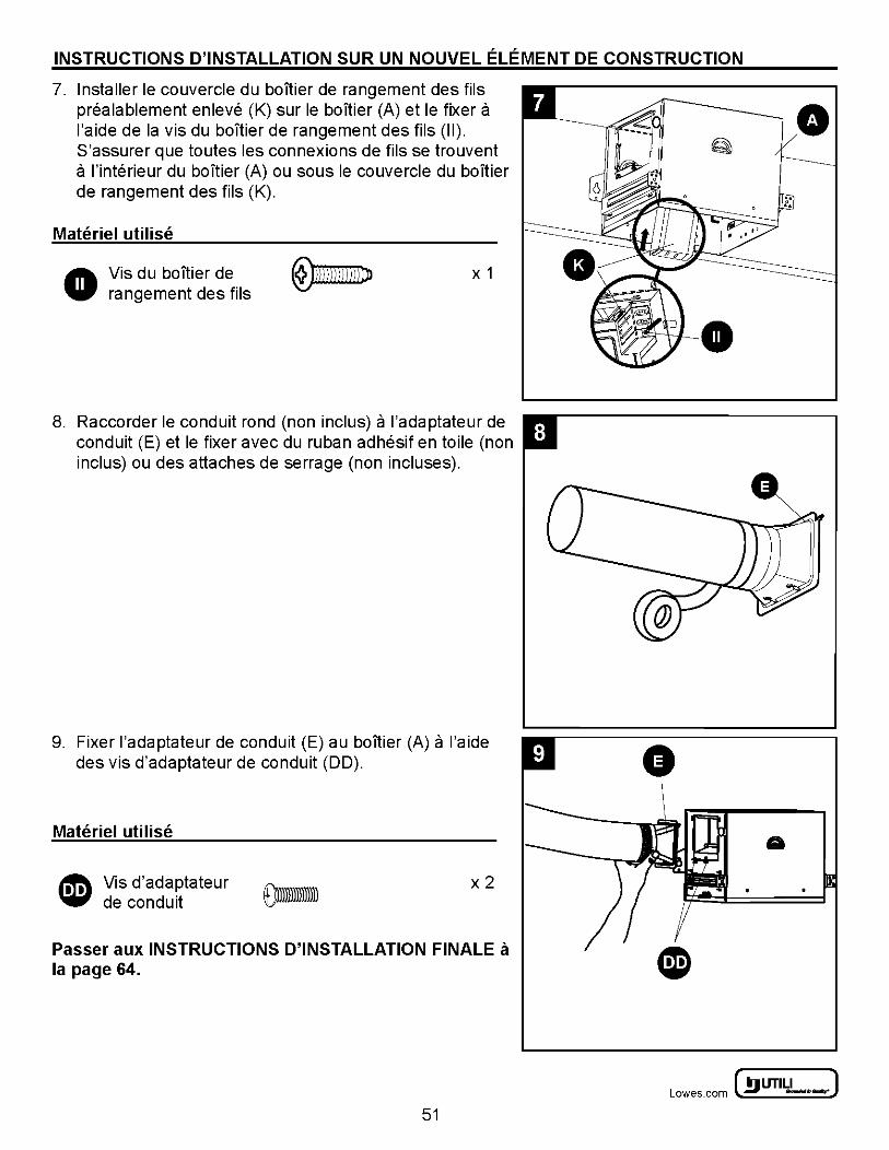
7. Installer le couvercle du baTtier derangement des fils prealablement enleve (K) sur le boltier (A) et le fixer a l'aide de Ia vis du boltier derangement des fils (II). S'assurer que toutes les connexions de fils se trouvent a l'interieur du boltier (A) ou sous le couvercle du baTtier de rangement des fils (K).
Materiel utilise
A Vis du boltier de W rangement des fils
X 1
8. Raccorder le conduit rond (non inclus) a l'adaptateur de conduit (E) et le fixer avec du ruban adhesif en toile (non inclus) ou des attaches de serrage (non incluses).
9. Fixer l'adaptateur de conduit (E) au boltier (A) a l'aide des vis d'adaptateur de conduit (DD).
Materiel utilise
I!!\ Vis d'adaptateur 'iii' de conduit
x2
Passer aux INSTRUCTIONS D'INSTALLATION FINALE a Ia page 64.
51
~ UTILITECH' ] Lowes.com l!l) -·-:
INSTRUCTIONS POUR L'INSTALLATION DANS LE CADRE D'UNE CONSTRUCTION EXISTANTE (SOLIVE/INSTALLATION AU PLAFOND AVEC ACCES PARLE HAUT)
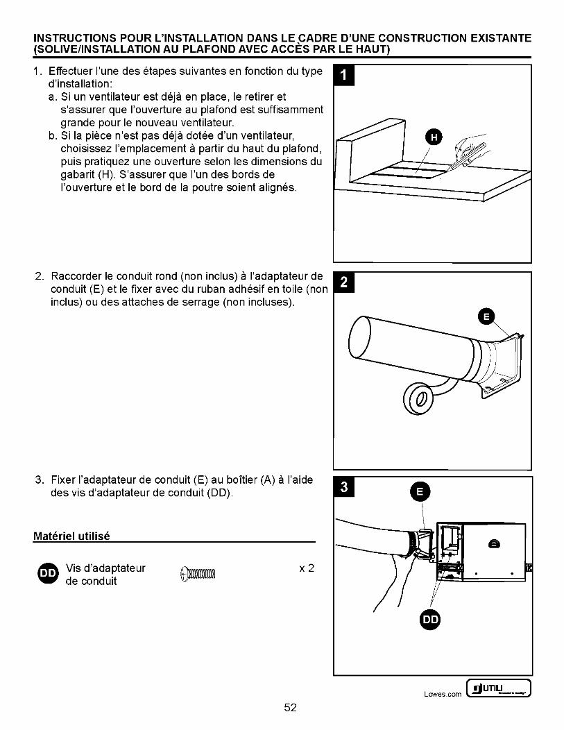
1. Effectuer l'une des etapes suivantes en fonction du type d'installation: a. Si un ventilateur est deja en place, le retirer et
s'assurer que l'ouverture au plafond est suffisamment grande pour le nouveau ventilateur.
b. Si Ia piece n'est pas deja dotee d'un ventilateur, choisissez !'emplacement a partir du haut du plafond, puis pratiquez une ouverture selon les dimensions du gabarit (H). S'assurer que l'un des bords de l'ouverture et le bord de Ia poutre soient alignes.
2. Raccorder le conduit rond (non inclus) a l'adaptateur de conduit (E) et le fixer avec du ruban adhesif en toile (non inclus) ou des attaches de serrage (non incluses).
3. Fixer l'adaptateur de conduit (E) au boltier (A) a l'aide des vis d'adaptateur de conduit (DD).
Materiel utilise
~ Vis d'adaptateur 'i6i' de conduit
x2
52
G
a
~UTILITECH' J Lowes .com ~ -·-
INSTRUCTIONS POUR L'INSTALLATION DANS LE CADRE D'UNE CONSTRUCTION EXISTANTE (SOLIVE/INSTALLATION AU PLAFOND AVEC ACCES PARLE HAUT)
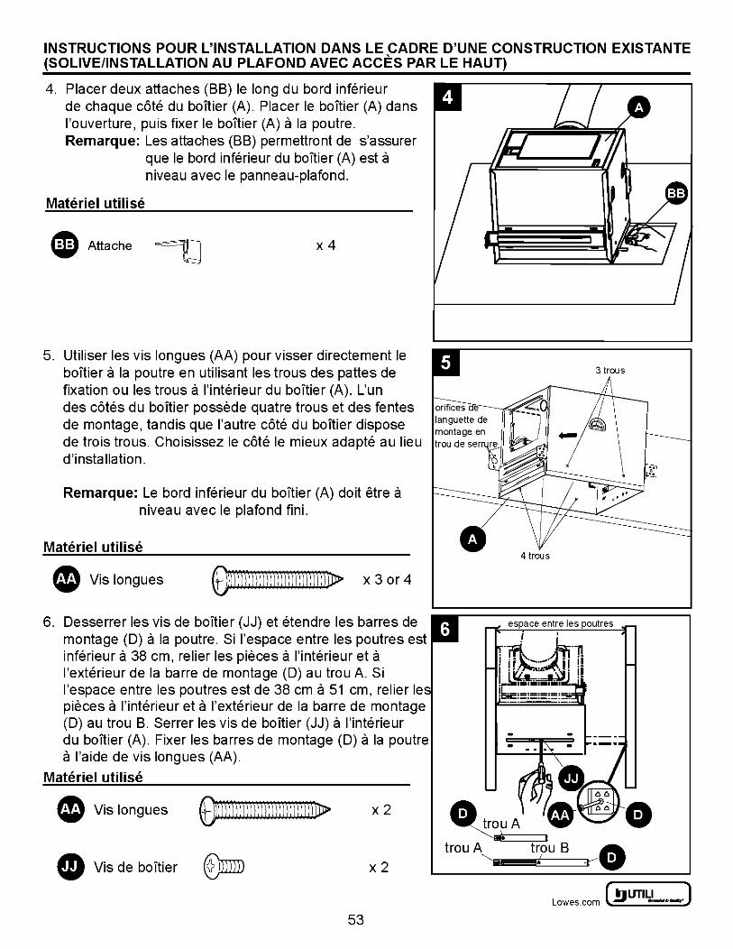
4. Placer deux attaches (BB) le long du bord inferieur de chaque cote du boltier (A). Placer le boltier (A) dans l'ouverture, puis fixer le boltier (A) a Ia poutre. Remarque: Les attaches (BB) permettront de s'assurer
que le bord inferieur du boltier (A) est a niveau avec le panneau-plafond.
Materiel utilise
ID Attache ~ x4
5. Utiliser les vis longues (AA) pour visser directement le boltier a Ia poutre en utilisant les trous des pattes de fixation ou les trous a l'interieur du boltier (A). L'un des cotes du boltier possede quatre trous et des fentes de montage, tandis que l'autre cote du boltier dispose de trois trous. Choisissez le cote le mieux adapte au lieu d'installation.
Remarque: Le bord inferieur du boltier (A) doit etre a niveau avec le plafond fini.
Materiel utilise
e Vis longues OmDJ)))))j)))))))))))))))!J> X 3 or 4
6. Desserrer les vis de boltier (JJ) et etendre les barres de montage (D) a Ia poutre. Si l'espace entre les poutres est inferieur a 38 em, relier les pieces a l'interieur eta l'exterieur de Ia barre de montage (D) au trou A. Si l'espace entre les poutres est de 38 em a 51 em, relier le pieces a l'interieur eta l'exterieur de Ia barre de montage (D) au trou B. Serrer les vis de boltier (JJ) a l'interieur du boltier (A). Fixer les barres de montage (D) a Ia poutre a l'aide de vis longues (AA).
Materiel utilise
e Vis longues ~))))) )) ) )) ))) \l) ))) ) ) ) ) lJJ) LD> x2
fD Vis de boltier x2
53
• 4 trous
~ UTILITECH' ] Lowes.com l!l) -·-:

INSTRUCTIONS POUR L'INSTALLATION DANS LE CADRE D'UNE CONSTRUCTION EXISTANTE (SOLIVE/INSTALLATION AU PLAFOND AVEC ACCES PARLE HAUT) 7. lnserer les fils existants provenant de !'emplacement
d'installation dans le trou de depart perce sur le boltier (A).
8. Connecter les fils selon le schema de cablage. a. Raccordez le fil noir du ventilateur au fil noir de l'interrupteur
du ventilateur a l'aide d'un raccord a branchement rapide a deux orifices (GG).
b. Raccordez le fil noir du luminaire au fil noir de l'interrupteur du luminaire a l'aide d'un raccord a branchement rapide a
deux orifices (GG). c. Raccordez le fil blanc du ventilateur au fil blanc du luminaire,
puis a l'entree de Ia ligne situee dans le plafond a l'aide du raccord a branchement rapide a trois orifices (HH).
d. Raccordez le fil rouge du luminaire au fil rouge de l'interrupteur de Ia veilleuse a l'aide d'un raccord a branchement rapide a deux orifices (GG).
e. Raccordez le fil de mise a Ia terre/vert de !'article au fil de mise a Ia terre situe dans le plafond a l'aide d'un raccord a branchement rapide a deux orifices (GG). Remarque: Pour une installation avec un seul interrupteur mural, retirez et coupez les 2 raccords transparents des 2 fils noirs du corps du ventilateur pour salle de bains. Denudez 12,7 mm de l'extremite des fils, puis raccordez les deux fils noirs au fil noir du plafond ou de l'interrupteur. Un interrupteur supplementaire est necessaire pour utiliser le fil rouge et Ia veilleuse.
6. Denudez 12,7 mm de l'extremite des fils. Tenez fermement le fil et poussez l'extremite denudee du fil dans !'orifice du raccord a branchement rapide a deux orifices (GG) ou du raccord a branchement rapide a trois orifices (HH). lnserez une seule extremite de fil denudee par orifice. Verifiez que l'extremite denudee du fil est inseree jusqu'au fond de !'orifice du raccord a branchement rapide a deux orifices (GG) ou du raccord a branchement rapide a trois orifices (HH).
Materiel utilise
Raccord a branchement rapide a deux orifices
Raccord a branchement rapide a trois orifices
x4
X 1
54
=Rogue = Blanc
Multi Control (purchase separately)
Apparel
Ligne de 120 V AC
maison
maison
~UTILITECH' J Lowes .com ~ -·-
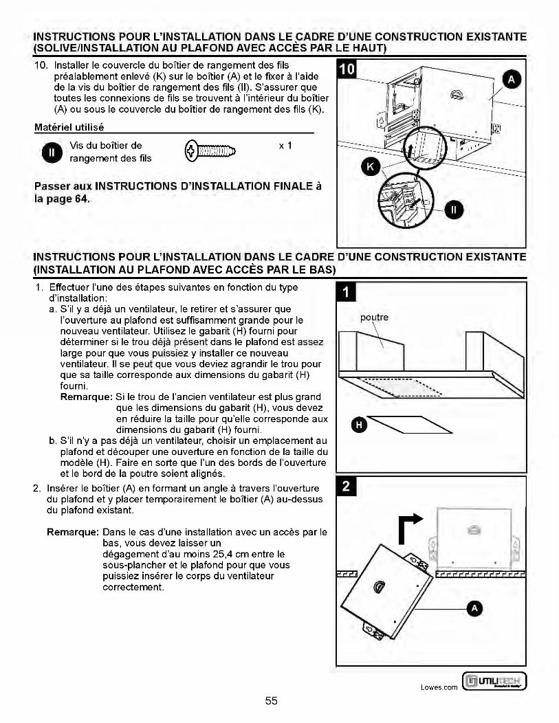
INSTRUCTIONS POUR L'INSTALLATION DANS LE CADRE D'UNE CONSTRUCTION EXISTANTE (SOLIVE/INSTALLATION AU PLAFOND AVEC ACCES PARLE HAUT)
10. Installer le couvercle du boltier de rangement des fils prealablement enleve (K) sur le boitier (A) et le fixer a l'aide de Ia vis du boitier de rangement des fils (II). S'assurer que toutes les connexions de fils se trouvent a l'interieur du boltier (A) ou sous le couvercle du boltier de rangement des fils (K).
Materiel utilise
A Vis du boltier de W rangement des fils
X 1
Passer aux INSTRUCTIONS D'INSTALLATION FINALE a Ia page 64.
INSTRUCTIONS POUR L'INSTALLATION DANS LE CADRE D'UNE CONSTRUCTION EXISTANTE (INSTALLATION AU PLAFOND AVEC ACCES PARLE BAS)
1. Effectuer l'une des etapes suivantes en fonction du type d'installation: a. S'il y a deja un ventilateur, le retirer et s'assurer que
l'ouverture au plafond est suffisamment grande pour le nouveau ventilateur. Utilisez le gabarit (H) fourni pour determiner si le trou deja present dans le plafond est assez large pour que vous puissiez y installer ce nouveau ventilateur. II se peut que vous deviez agrandir le trou pour que sa taille corresponde aux dimensions du gabarit (H) fourni. Remarque: Si le trou de l'ancien ventilateur est plus grand
que les dimensions du gabarit (H), vous devez en reduire Ia taille pour qu'elle corresponde aux dimensions du gabarit (H) fourni.
b. S'il n'y a pas deja un ventilateur, choisir un emplacement au plafond et decouper une ouverture en fonction de Ia taille du modele (H). Faire en sorte que l'un des bords de l'ouverture et le bord de Ia poutre soient alignes.
2. lnserer le boltier (A) en formant un angle a travers l'ouverture du plafond et y placer temporairement le boitier (A) au-dessus du plafond existant.
Remarque: Dans le cas d'une installation avec un acces par le bas, vous devez laisser un degagement d'au moins 25,4 em entre le sous-plancher et le plafond pour que vous puissiez inserer le corps du ventilateur correctement.
55
.. ··. _________ : .......
~ UTILITECH' ] Lowes.com l!l) -·-:
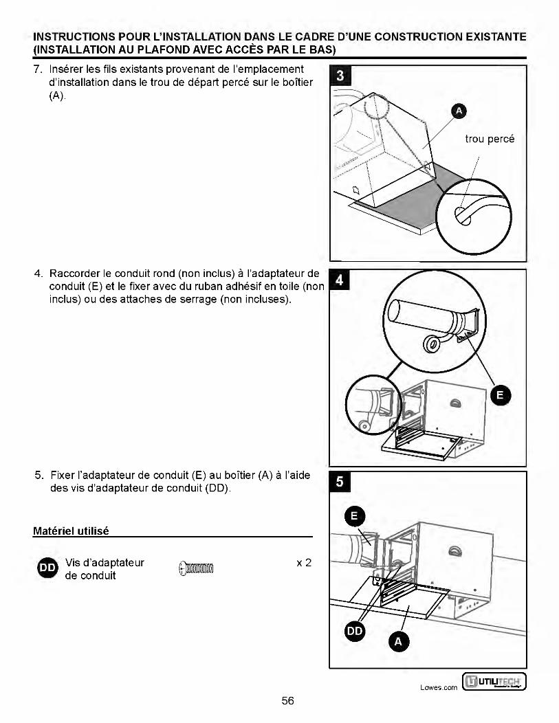
INSTRUCTIONS POUR L'INSTALLATION DANS LE CADRE D'UNE CONSTRUCTION EXISTANTE (INSTALLATION AU PLAFOND AVEC ACCES PARLE BAS)
7. lnserer les fils existants provenant de !'emplacement d'installation dans le trou de depart perce sur le boltier (A).
4. Raccorder le conduit rond (non inclus) a l'adaptateur de conduit (E) et le fixer avec du ruban adhesif en toile (non inclus) ou des attaches de serrage (non incluses).
5. Fixer l'adaptateur de conduit (E) au boltier (A) a l'aide des vis d'adaptateur de conduit (DD).
Materiel utilise
~ Vis d'adaptateur 'i6i' de conduit
x2
56
trou perce
~UTILITECH' J Lowes .com ~ -·-
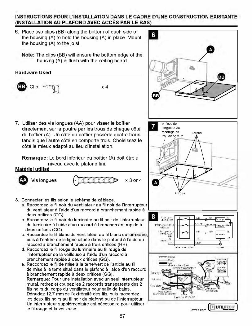
INSTRUCTIONS POUR L'INSTALLATION DANS LE CADRE D'UNE CONSTRUCTION EXISTANTE (INSTALLATION AU PLAFOND AVEC ACCES PARLE BAS)
6. Place two clips (BB) along the bottom of each side of the housing (A) to hold the housing (A) in place. Mount the housing (A) to the joist.
Note: The clips (BB) will ensure the bottom edge of the housing (A) is flush with the ceiling board.
Hardware Used
eclip~ x4
7. Utiliser des vis longues (AA) pour visser le boitier directement sur Ia poutre par les trous de chaque cote du boltier (A). Un cote du boitier possede quatre trous tandis que l'autre cote en comporte trois. Choisissez le cote le mieux adapte au lieu d'installation.
Remarque: Le bard inferieur du boitier (A) doit etre a niveau avec le plafond fini.
Materiel utilise
e Vis longues ~)ffi))ll))j)))))j))))l))))lJD> x 3 or 4
8. Connecter les fils selon le schema de cablage. a. Raccordez le fil noir du ventilateur au fil noir de l'interrupteur
du ventilateur a l'aide d'un raccord a branchement rapide a deux orifices (GG).
b. Raccordez le fil noir du luminaire au fil noir de l'interrupteur du luminaire a l'aide d'un raccord a branchement rapide a deux orifices (GG).
c. Raccordez le fil blanc du ventilateur au fil blanc du luminaire, puis a l'entree de Ia ligne situee dans le plafond a l'aide du raccord a branchement rap ide a trois orifices (H H).
d. Raccordez le fil rouge du luminaire au fil rouge de l'interrupteur de Ia veilleuse a l'aide d'un raccord a branchement rap ide a deux orifices (GG).
e. Raccordez le fil de mise a Ia terre/vert de !'article au fil de mise a Ia terre situe dans le plafond a l'aide d'un raccord a branchement rapide a deux orifices (GG). Remarque: Pour une installation avec un seul interrupteur mural, retirez et coupez les 2 raccords transparents des 2 fils noirs du corps du ventilateur pour salle de bains. Denudez 12,7 mm de l'extremite des fils, puis raccordez les deux fils noirs au fil noir du plafond ou de l'interrupteur. Un interrupteur supplementaire est necessaire pour utiliser le fil rouge et Ia veilleuse.
57
lnterTUpteur de Ia vei!leuse
= Rogue = Blanc - Notr --MISe a Ia terTe (nu)
Boll ier d'interTupteur
Multi Control (purchase separately)
Ligne de 120 V AC
~ UTILITECH' ] Lowes.com l!l) -·-:
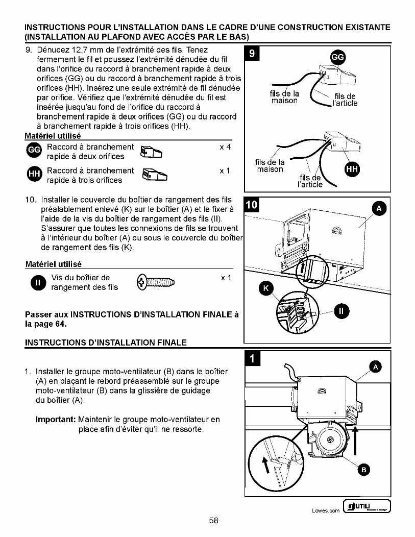
INSTRUCTIONS POUR L'INSTALLATION DANS LE CADRE D'UNE CONSTRUCTION EXISTANTE (INSTALLATION AU PLAFOND AVEC ACCES PARLE BAS)
9. Denudez 12,7 mm de l'extremite des fils. Tenez fermement le filet poussez l'extremite denudee du fil dans !'orifice du raccord a branchement rapide a deux orifices (GG) ou du raccord a branchement rapide a trois orifices (HH). lnserez une seule extremite de fil denudee par orifice. Verifiez que l'extremite denudee du fil est inseree jusqu'au fond de !'orifice du raccord a branchement rapide a deux orifices (GG) ou du raccord a branchement rapide a trois orifices (HH).
Materiel utilise ~ Raccor? a branchement ~ 'iii' rapide a deux orifices ~
lfft\ Raccord a branchement ~ ..., rapide a trois orifices
x4
X 1 fils de Ia maison
10. Installer le couvercle du boltier de rangement des fils prealablement enleve (K) sur le boitier (A) et le fixer a l'aide de Ia vis du boltier de rangement des fils (II). ------------------~b~ S'assurer que toutes les connexions de fils se trouvent !/ ,~ J II a l'interieur du bolti~r (A) ou so us le couvercle du boltier ~J ~~..11 de rangement des f1ls (K). 11 - '
Materiel utilise
A Vis du boitier de W rangement des fils
X 1
Passer aux INSTRUCTIONS D'INSTALLATION FINALE a Ia page 64.
INSTRUCTIONS D'INSTALLATION FINALE
1. Installer le groupe moto-ventilateur (B) dans le boitier (A) en pla9ant le rebord preassemble sur le groupe moto-ventilateur (B) dans Ia glissiere de guidage du boltier (A).
Important: Maintenir le groupe moto-ventilateur en place afin d'eviter qu'il ne ressorte.
58
•
~UTILITECH" J Lowes .com ~ -·-
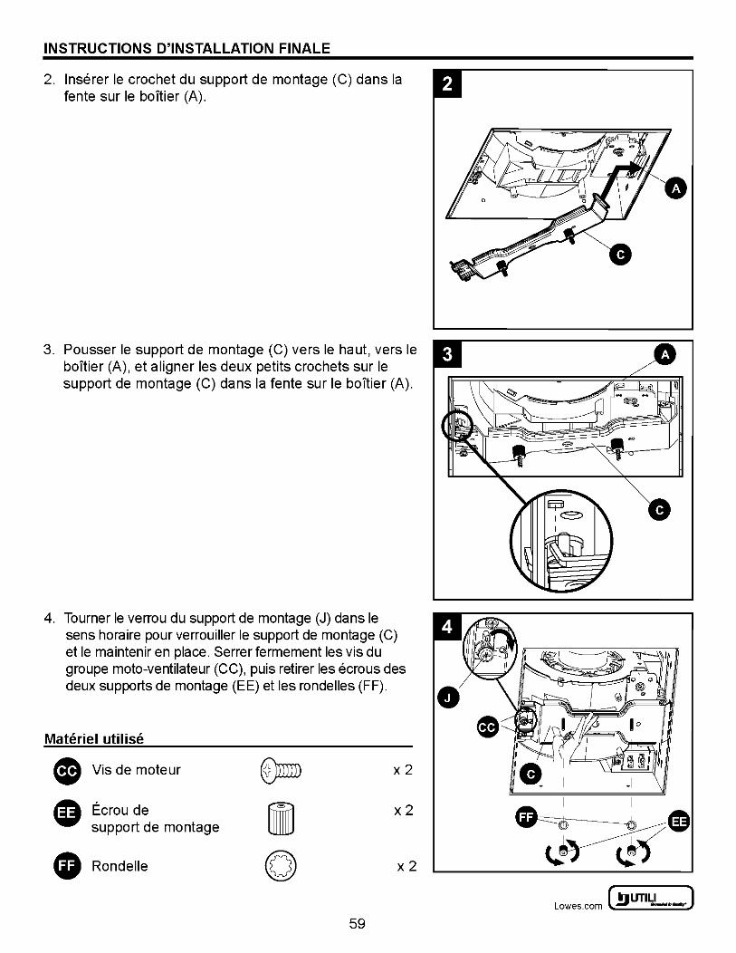
INSTRUCTIONS D'INSTALLATION FINALE
2. lnserer le crochet du support de montage (C) dans Ia fente sur le boitier (A).
3. Pousser le support de montage (C) vers le haut, vers le baTtier (A), et aligner les deux petits crochets sur le support de montage (C) dans Ia fente sur le boltier (A).
4. Tourner le verrou du support de montage (J) dans le sens horaire pour verrouiller le support de montage (C) et le maintenir en place. Serrer fermement les vis du groupe moto-ventilateur (CC), puis retirer les ecrous des deux supports de montage (EE) et les rondelles (FF).
Materiel utilise
Vis de moteur x2
Ecrou de x2 support de montage
Rondelle x2
59
0
~ UTILITECH' ] Lowes.com l!l) -·-:
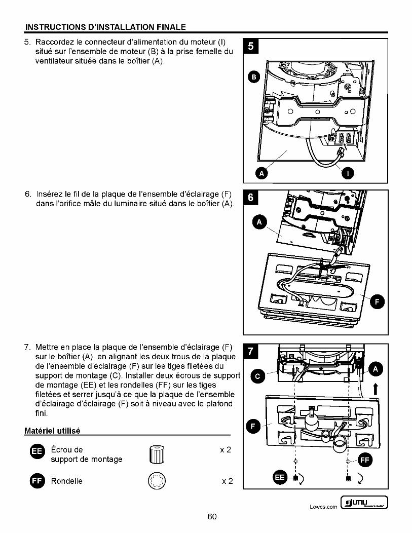
INSTRUCTIONS D'INSTALLATION FINALE
5. Raccordez le connecteur d'alimentation du moteur (I) situe sur !'ensemble de moteur (B) a Ia prise femelle du ventilateur situee dans le baTtier (A).
6. lnserez le fil de Ia plaque de !'ensemble d'eclairage (F) dans !'orifice male du luminaire situe dans le baTtier (A).
7. Mettre en place Ia plaque de !'ensemble d'eclairage (F) sur le boltier (A), en alignant les deux trous de Ia plaque de !'ensemble d'eclairage (F) sur les tiges filetees du support de montage (C). Installer deux ecrous de support de montage (EE) et les ronde lies (FF) sur les tiges filetees et serrer jusqu'a ce que Ia plaque de !'ensemble d'eclairage d'eclairage (F) soit a niveau avec le pia fond fini.
Materiel utilise
Ecrou de x2 support de montage
Ronde lie x2
60
• 0
I
tl )
~UTILITECH" J Lowes .com ~ -·-
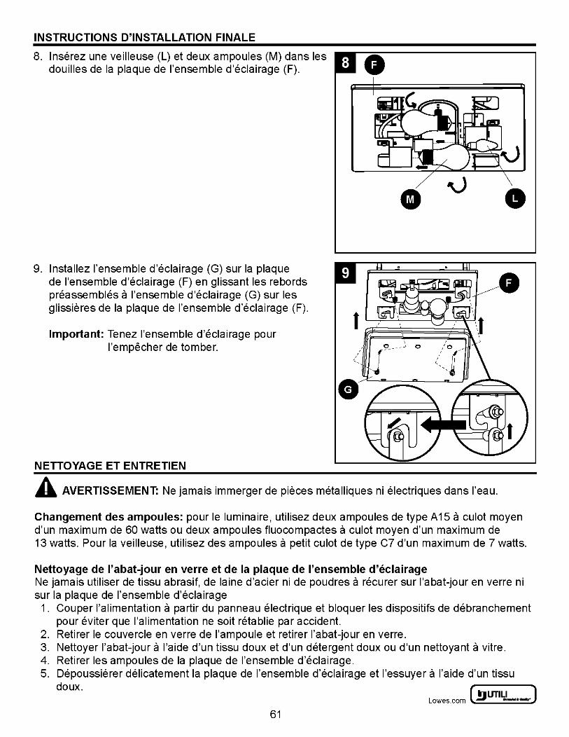
INSTRUCTIONS D'INSTALLATION FINALE
8. lnserez une veilleuse (L) et deux ampoules (M) dans les 0 douilles de Ia plaque de !'ensemble d'eclairage (F).
9. lnstallez !'ensemble d'eclairage (G) sur Ia plaque
• • de !'ensemble d'eclairage (F) en glissant les rebords preassembles a !'ensemble d'eclairage (G) sur les glissieres de Ia plaque de !'ensemble d'eclairage (F).
t~~ Important: Tenez !'ensemble d'eclairage pour
l'empecher de tomber.
NETTOYAGE ET ENTRETIEN
,/ !C?- - - -~' 0 ,_
'
• A AVERTISSEMENT: Ne jamais immerger de pieces metalliques ni electriques dans l'eau.
Changement des ampoules: pour le luminaire, utilisez deux ampoules de type A15 a culot moyen d'un maximum de 60 watts ou deux ampoules fluocompactes a culot moyen d'un maximum de 13 watts. Pour Ia veilleuse, utilisez des ampoules a petit culot de type C7 d'un maximum de 7 watts.
Nettoyage de l'abat-jour en verre et de Ia plaque de !'ensemble d'eclairage Ne jamais utiliser de tissu abrasif, de Iaine d'acier ni de poudres a recurer sur l'abat-jour en verre ni sur Ia plaque de !'ensemble d'eclairage
1. Couper !'alimentation a partir du panneau electrique et bloquer les dispositifs de debranchement pour eviter que !'alimentation ne soit retablie par accident.
2. Retirer le couvercle en verre de !'ampoule et retirer l'abat-jour en verre. 3. Nettoyer l'abat-jour a l'aide d'un tissu doux et d'un detergent doux ou d'un nettoyant a vitre. 4. Retirer les ampoules de Ia plaque de !'ensemble d'eclairage. 5. Depoussierer delicatement Ia plaque de !'ensemble d'eclairage et l'essuyer a l'aide d'un tissu
doux. ~ UTILITECH' ] Lowes.com l!l) -·-:
61
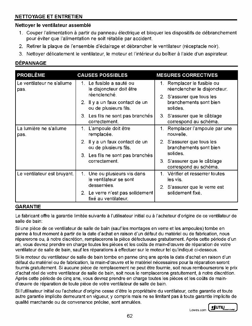
NETTOYAGE ET ENTRETIEN
Nettoyer le ventilateur assemble
1. Couper !'alimentation a partir du panneau electrique et bloquer les dispositifs de debranchement pour eviter que !'alimentation ne soit retablie par accident.
2. Retirer Ia plaque de !'ensemble d'eclairage et debrancher le ventilateur (receptacle noir).
3. Nettoyer delicatement le ventilateur, le moteur et l'interieur du boltier a l'aide d'un aspirateur.
DEPANNAGE
PROBLEME CAUSES POSSIBLES MESURES CORRECTIVES
Le ventilateur ne s'allume 1. Le fusible a saute ou 1. Remplacer le fusible ou pas. le disjoncteur doit etre reenclencher le disjoncteur.
reenclenche. 2. S'assurer que tous les 2. II y a un faux contact de un branchements sont bien
ou de plusieurs fils. solides.
3. Les fils ne sont pas branches 3. S'assurer que le cablage correctement. correspond au schema.
La lumiere ne s'allume 1. L'ampoule doit etre 1. Remplacer !'ampoule par une pas. remplacee. nouvelle.
2. II y a un faux contact de un 2. S'assurer que tous les ou de plusieurs fils. branchements sont bien
3. Les fils ne sont pas branches solides.
correctement. 3. S'assurer que le cablage correspond au schema.
Le ventilateur est bruyant. 1. Une ou plusieurs vis dans 1. Verifier et resserrer toutes le ventilateur se sont les vis. desserrees. 2. S'assurer que le verre est
2. Le verre n'est pas solidement solidement fixe. fixe au ventilateur.
GARANTIE
Le fabricant offre Ia garantie limitee suivante a l'utilisateur initial ou a l'acheteur d'origine de ce ventilateur de salle de bain:
Si une piece de ce ventilateur de salle de bain (sauf les montages en verre et les ampoules) tom be en panne a tout moment a partir de Ia date d'achat en raison d'un defaut du materiel ou de fabrication, nous reparerons ou, a notre discretion, remplacerons Ia piece defectueuse gratuitement. Apres cette periode d'un an, vous devrez prendre en charge toutes les pieces et les coOts de main-d'ceuvre de reparation de votre ventilateur de salle de bain, sauf les reparations a effectuer sur le moteur tel qu'indique ci-dessous.
Si le moteur du ventilateur de salle de bain tombe en panne cinq ans apres Ia date d'achat en raison d'un defaut du materiel ou de fabrication, Ia main-d'ceuvre et le materiel necessaires pour Ia reparation seront fournis gratuitement. Si aucune piece de remplacement ne peut etre fournie, soit nous rembourserons le prix d'achat reel de votre ventilateur de salle de bain, soit nous le remplacerons gratuitement, a notre discretion. Apres cette periode de cinq ans, vous devrez prendre en charge toutes les pieces et les coOts de maind'ceuvre de reparation de toute piece de votre ventilateur de salle de bain.
Si l'utilisateur initial ou l'acheteur d'origine cesse d'etre le proprietaire du ventilateur, cette garantie et toute autre garantie implicite demeurant en vigueur, y compris mais ne se limitant pas a toute garantie implicite de qualite marchande ou de convenance precise, sont annulees.
~UTILITECH" J Lowes .com ~ -·-
62
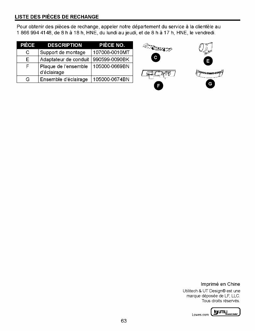
LISTE DES PIECES DE RECHANGE
Pour obtenir des pieces de rechange, appeler notre departement du service a Ia clientele au 1 866 994 4148, de 8 h a 18 h, H NE, du lundi au jeudi, et de 8 h a 17 h, HNE, le vendredi.
PIECE DESCRIPTION c Support de montage
E Adaptateur de conduit
F Plaque de !'ensemble d'eclairage
G Ensemble d'eclairage
PIECE NO. 1 07008-001 OMT
990599-0090BK
1 05000-0669BN
1 05000-067 4BN
63
lmprime en Chine Utilitech & UT Design® est une
marque deposee de LF, LLC. Taus droits reserves.
~ UTILITECH' ] Lowes.com l!l) -·-: