Embed Size (px)
Citation preview
with Excalibur Devices Tutorial
Using SOPC Builder
101 Innovation DriveSan Jose, CA 95134(408) 544-7000http://www.altera.com
Document Version: 1.0Document Date: July 2002

ii Altera CorporationTU-SOPCTTRL1.0
Copyright Excalibur Devices Using SOPC Builder Tutorial
Copyright © 2002 Altera Corporation. All rights reserved. Altera, The Programmable Solutions Company, the stylized Altera logo,specific device designations, and all other words and logos that are identified as trademarks and/or service marks are, unlessnoted otherwise, the trademarks and service marks of Altera Corporation in the U.S. and other countries. All other product orservice names are the property of their respective holders. Altera products are protected under numerous U.S. and foreign patentsand pending applications, mask work rights, and copyrights. Altera warrants performance of its semiconductorproducts to current specifications in accordance with Altera’s standard warranty, but reserves the right to makechanges to any products and services at any time without notice. Altera assumes no responsibility or liabilityarising out of the application or use of any information, product, or service described herein except as expresslyagreed to in writing by Altera Corporation. Altera customers are advised to obtain the latest version of devicespecifications before relying on any published information and before placing orders for products or services.

Altera Corporation
About this Document
This tutorial introduces you to the Altera® SOPC Builder. It shows you how to use the Quartus® II software to create and build your own SOPC Builder minimal_arm system module that interfaces with the EPXA10 development board.
Table 1 shows the tutorial revision history.
f Refer to the SOPC Builder readme file (sopc_builder_readme) for late-breaking information that is not available in this tutorial.
How to Find Information
■ The Adobe Acrobat Find feature allows you to search the contents of a PDF file. Click the binoculars toolbar icon to open the Find dialog box.
■ Bookmarks serve as an additional table of contents.■ Thumbnail icons, which provide miniature previews of each page,
provide a link to the pages.■ Numerous links, shown in green text, allow you to jump to related
information.
Table 1. Tutorial Revision History
Date Description
July 2002 Tutorial showing the steps to create the minimal_arm system module using SOPC Builder
iii
About this Document Excalibur Devices SOPC Builder Tutorial
How to Contact Altera
For the most up-to-date information about Altera products, go to the Altera world-wide web site at http://www.altera.com.
For technical support on this product, go to http://www.altera.com/mysupport. For additional information about Altera products, consult the sources shown in Table 2.
Note:(1) You can also contact your local Altera sales office or sales representative.
Table 2. How to Contact Altera
Information Type USA & Canada All Other Locations
Technical support http://www.altera.com/mysupport/ http://www.altera.com/mysupport/
(800) 800-EPLD (3753)(7:00 a.m. to 5:00 p.m. Pacific Time)
(408) 544-7000 (1)(7:00 a.m. to 5:00 p.m. Pacific Time)
Product literature http://www.altera.com http://www.altera.com
Altera literature services [email protected] (1) [email protected] (1)
Non-technical customer service
(800) 767-3753 (408) 544-7000 (7:30 a.m. to 5:30 p.m. Pacific Time)
FTP site ftp.altera.com ftp.altera.com
iv Altera Corporation
Excalibur Devices SOPC Builder Tutorial About this Document
Typographic Conventions
The Using SOPC Builder with Excalibur Devices Tutorial uses the typographic conventions shown in Table 3.
Table 3. Conventions
Visual Cue Meaning
Bold Type with Initial Capital Letters
Command names, dialog box titles, checkbox options, and dialog box options are shown in bold, initial capital letters. Example: Save As dialog box.
bold type External timing parameters, directory names, project names, disk drive names, filenames, filename extensions, and software utility names are shown in bold type. Examples: fMAX, \qdesigns directory, d: drive, chiptrip.gdf file.
Italic Type with Initial Capital Letters
Document titles are shown in italic type with initial capital letters. Example: AN 75: High-Speed Board Design.
Italic type Internal timing parameters and variables are shown in italic type. Examples: tPIA, n + 1.Variable names are enclosed in angle brackets (< >) and shown in italic type. Example: <file name>, <project name>.pof file.
Initial Capital Letters Keyboard keys and menu names are shown with initial capital letters. Examples: Delete key, the Options menu.
“Subheading Title” References to sections within a document and titles of on-line help topics are shown in quotation marks. Example: “Typographic Conventions.”
Courier type Signal and port names are shown in lowercase Courier type. Examples: data1, tdi, input. Active-low signals are denoted by suffix n, e.g., resetn.
Anything that must be typed exactly as it appears is shown in Courier type. For example: c:\qdesigns\tutorial\chiptrip.gdf. Also, sections of an actual file, such as a Report File, references to parts of files (e.g., the AHDL keyword SUBDESIGN), as well as logic function names (e.g., TRI) are shown in Courier.
1., 2., 3., and a., b., c.,... Numbered steps are used in a list of items when the sequence of the items is important, such as the steps listed in a procedure.
■ Bullets are used in a list of items when the sequence of the items is not important.
v The checkmark indicates a procedure that consists of one step only.
1 The hand points to information that requires special attention.
r The angled arrow indicates you should press the Enter key.
f The feet direct you to more information on a particular topic.
Altera Corporation v


Contents
About this Document ................................................................................................................................. iiiHow to Find Information .............................................................................................................. iiiHow to Contact Altera .................................................................................................................. ivTypographic Conventions ..............................................................................................................v
Tutorial Overview .........................................................................................................................................9Introduction ......................................................................................................................................9Hardware & Software Requirements ..........................................................................................10Tutorial Files ...................................................................................................................................10More Information ...........................................................................................................................11
Design Entry .................................................................................................................................................11Create a Quartus II Project ............................................................................................................11
Start the Quartus II Software ................................................................................................11Create a Project .......................................................................................................................11
Create an Excalibur System Module ...........................................................................................15Create a New .bdf ..................................................................................................................16Start SOPC Builder .................................................................................................................17Add CPU & Peripherals ........................................................................................................20
Excalibur Device ...........................................................................................................21AHB To Avalon Bridge .................................................................................................25Output PIO ......................................................................................................................26
Set the Clock Rate ..................................................................................................................27Specify Base Addresses .........................................................................................................28Set the Excalibur Device ........................................................................................................29Generate minimal_arm System & Add It to the Design ..................................................29Add the Symbol to the .bdf ..................................................................................................31Add Pins & Primitives ...........................................................................................................33Name the Pins .........................................................................................................................35Make the Final Connections .................................................................................................37
Compilation ..................................................................................................................................................39Create Compiler Settings ..............................................................................................................39
View the Compiler General Settings ...................................................................................40Specify the Device Family & Device ...................................................................................40
Altera Corporation vii

Contents Excalibur Devices Using SOPC Builder Tutorial
Assign Signals to Device Pins ......................................................................................................42Reassign Pins ..........................................................................................................................43
Specify Device, Programming & EDA Tool Settings ................................................................44Reserve Unused Pins .............................................................................................................44Verify EDA Tool Settings ......................................................................................................47
Compile the Design .......................................................................................................................48
Programming ...............................................................................................................................................51Software Build ................................................................................................................................51
Verify ADS Standard Tools ..................................................................................................53Select Software Build Settings ..............................................................................................54Download Executable Files to the Excalibur Device Board .............................................57
Next Steps .......................................................................................................................................58
viii Altera Corporation
Altera Corporation
Tut
1
Tutorial Overview
orial Overview
Introduction This tutorial introduces you to the Excalibur devices used with the SOPC Builder. It shows you how to use SOPC Builder and the Quartus® II software to create and process your own Excalibur device system module design that interfaces with components provided on the EPXA10 development board.This tutorial assumes you have read the following documents:
■ AN 174 - Excalibur Solutions Hello_world.c■ EPXA10 Development Kit Getting Started User Guide
This tutorial is for SOPC Builder novices or users who are new to using embedded systems in PLDs. The tutorial guides you through the steps necessary to create, build the software and simulate an Excalibur hardware design system module, called minimal_arm, and download it into the EPXA10 development board. This simple, single-master system module has an Excalibur device processor and associated advanced microprocessor bus architecture (AMBA) hardware bus (AHB) system peripherals and interconnections.
After you create the minimal_arm_system design and connect to external pins, you can download it to the Altera® Excalibur device on the EPXA10 development board. The external physical pins on the Excalibur device are in turn connected to other hardware components on the EPXA10 development board, allowing the ARM-based Excalibur Stripe to interface with SDRAM, flash memory, LEDs, switches, and buttons.
This tutorial is divided into the following three sections:
■ “Design Entry” on page 11 teaches you how to create the Excalibur device system module in a block design file (.bdf) using the MegaWizard® Plug-In Manager and the SOPC Builder.
■ “Compilation” on page 39 teaches you how to compile the SOPC Builder design using compiler settings, pin assignments, and EDA tool settings to control compilation processing.
■ “Programming” on page 51 teaches you how to use the Quartus II software to add the software files needed for the minimal_arm project, set the software build settings and select the links for
9
Excalibur Devices Using SOPC Builder Tutorial Tutorial Overview
simulating the project. This section also teaches you how to download the hardware and software image file to the device on the EPXA10 development board.
Hardware & Software Requirements
This tutorial requires the following hardware and software:
■ A PC running the Windows NT or 2000 operating system■ ARM Development Suite (ADS) software development tool with
license■ ModelSim® Altera Edition version 5.6a or higher■ Quartus II software version 2.0 or higher■ A EPXA10 development board, set up as described in the EXPA10
Development Kit Getting Started User Guide■ The ByteBlasterMVTM driver, installed as described in the Quartus II
Installation & Licensing for PCs manual
1 When you install SOPC Builder, the installation program also installs the LeonardoSpectrumTM software. SOPC Builder uses LeonardoSpectrum software when synthesizing a system module. You can request a free license file for this software on the license Altera web site at http://www.altera.com. Your license file also contains a license for the Quartus II software.
Tutorial Files This tutorial assumes that you create and save your files in a working directory on the c: drive on your computer. If your working directory is on another drive, substitute the appropriate drive name.
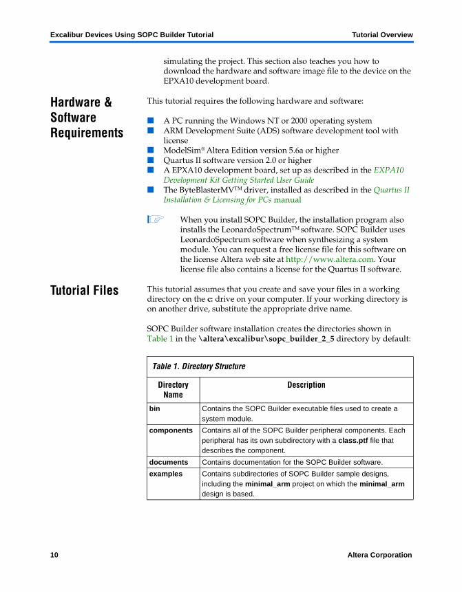
SOPC Builder software installation creates the directories shown in Table 1 in the \altera\excalibur\sopc_builder_2_5 directory by default:
Table 1. Directory Structure
Directory Name
Description
bin Contains the SOPC Builder executable files used to create a system module.
components Contains all of the SOPC Builder peripheral components. Each peripheral has its own subdirectory with a class.ptf file that describes the component.
documents Contains documentation for the SOPC Builder software.
examples Contains subdirectories of SOPC Builder sample designs, including the minimal_arm project on which the minimal_arm design is based.
10 Altera Corporation

Tutorial Overview Excalibur Devices Using SOPC Builder Tutorial
Tutorial Overview
1
More Information
SOPC Builder includes the Excalibur device, which supports features such as AHB. For more Excalibur-related and SOPC builder information see the documents available at http://www. altera.com/literature/lit-index.html.
tutorials Contains the files that you can use with the SOPC Builder version 2.51 tutorials. The directory for this tutorial document is sopc_arm_tutorial.
Altera Corporation 11

Altera Corporation
Design Entry
Design Entry
2
The following tutorial sections guide you through the steps required to create the Excalibur device system module project that includes how to create a top-level block-level diagram (.bdf) containing the Excalibur device system module. You will create and instantiate the Excalibur device system module using the SOPC Builder.
1 The instructions in this section assume that you are familiar with the Quartus II software interface, specifically the toolbars. Refer to the Quartus II Help for information that is not included in the tutorial.
Create a Quartus II Project
Start the Quartus II Software
In this section, you start the Quartus II software and begin creating your project.
v Choose Start > Programs > Altera > Quartus II <version> (Windows Start menu) to start the Quartus II software.
Create a Project
Before you begin, you must create a new Quartus II project. With the New Project wizard, you specify the working directory for the project, assign the project name, and designate the name of the top-level design entity. To create a new project, perform the following steps:
1. Choose New Project Wizard (File menu).
2. Click Next in the introduction (the introduction does not display if you turned it off previously).
3. Specify the working directory for your project. This tutorial uses the directory c:\altera\excalibur\sopc_builder_2_5\tutorials\sopc_arm_tutorial.
11
Design Entry Excalibur Devices Using SOPC Builder Tutorial
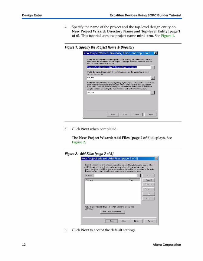
4. Specify the name of the project and the top-level design entity on New Project Wizard: Directory Name and Top-level Entity [page 1 of 6]. This tutorial uses the project name mini_arm. See Figure 1.
Figure 1. Specify the Project Name & Directory
5. Click Next when completed.
The New Project Wizard: Add Files [page 2 of 6] displays. See Figure 2.
Figure 2. Add Files [page 2 of 6]
6. Click Next to accept the default settings.
12 Altera Corporation
Excalibur Devices Using SOPC Builder Tutorial Design Entry
Design Entry
2
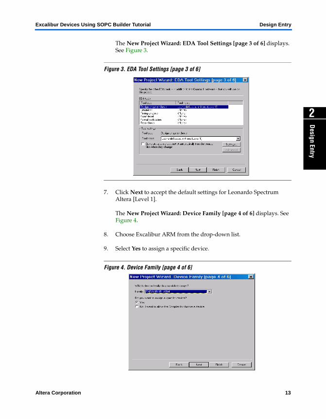
The New Project Wizard: EDA Tool Settings [page 3 of 6] displays. See Figure 3.
Figure 3. EDA Tool Settings [page 3 of 6]
7. Click Next to accept the default settings for Leonardo Spectrum Altera [Level 1].
The New Project Wizard: Device Family [page 4 of 6] displays. See Figure 4.
8. Choose Excalibur ARM from the drop-down list.
9. Select Yes to assign a specific device.
Figure 4. Device Family [page 4 of 6]
Altera Corporation 13
Design Entry Excalibur Devices Using SOPC Builder Tutorial
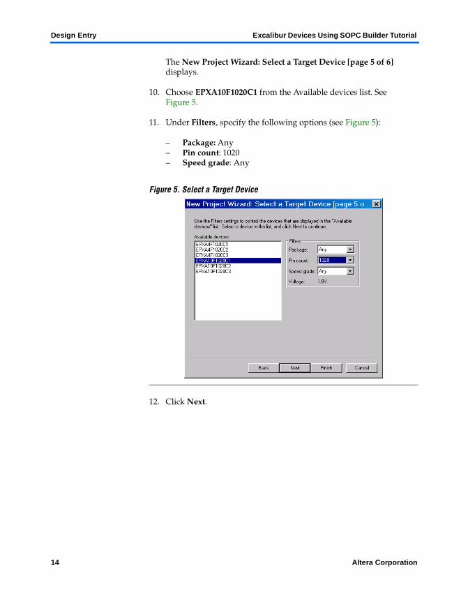
The New Project Wizard: Select a Target Device [page 5 of 6] displays.
10. Choose EPXA10F1020C1 from the Available devices list. See Figure 5.
11. Under Filters, specify the following options (see Figure 5):
– Package: Any– Pin count: 1020– Speed grade: Any
Figure 5. Select a Target Device
12. Click Next.
14 Altera Corporation
Excalibur Devices Using SOPC Builder Tutorial Design Entry
Design Entry
2
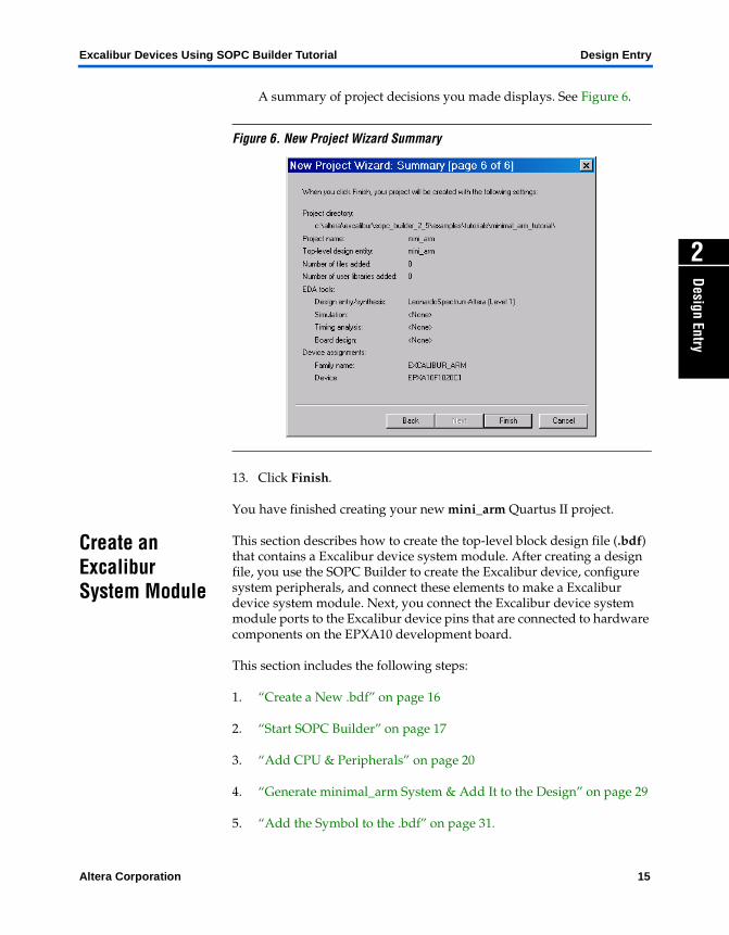
A summary of project decisions you made displays. See Figure 6.
Figure 6. New Project Wizard Summary
13. Click Finish.
You have finished creating your new mini_arm Quartus II project.
Create an Excalibur System Module
This section describes how to create the top-level block design file (.bdf) that contains a Excalibur device system module. After creating a design file, you use the SOPC Builder to create the Excalibur device, configure system peripherals, and connect these elements to make a Excalibur device system module. Next, you connect the Excalibur device system module ports to the Excalibur device pins that are connected to hardware components on the EPXA10 development board.
This section includes the following steps:
1. “Create a New .bdf” on page 16
2. “Start SOPC Builder” on page 17
3. “Add CPU & Peripherals” on page 20
4. “Generate minimal_arm System & Add It to the Design” on page 29
5. “Add the Symbol to the .bdf” on page 31.
Altera Corporation 15
Design Entry Excalibur Devices Using SOPC Builder Tutorial
6. “Add Pins & Primitives” on page 33
7. “Name the Pins” on page 35
8. “Make the Final Connections” on page 37.
Create a New .bdf
In this step you create a new .bdf called minimal_arm.bdf. This file is the top-level design entity of the minimal_arm project.
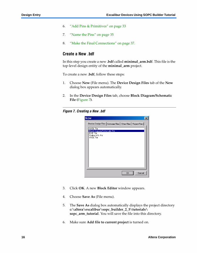
To create a new .bdf, follow these steps:
1. Choose New (File menu). The Device Design Files tab of the New dialog box appears automatically.
2. In the Device Design Files tab, choose Block Diagram/Schematic File (Figure 7).
Figure 7. Creating a New .bdf
3. Click OK. A new Block Editor window appears.
4. Choose Save As (File menu).
5. The Save As dialog box automatically displays the project directory c:\altera\excalibur\sopc_builder_2_5\tutorials\sopc_arm_tutorial. You will save the file into this directory.
6. Make sure Add file to current project is turned on.
16 Altera Corporation
Excalibur Devices Using SOPC Builder Tutorial Design Entry
Design Entry
2
7. In the File name box, type mini_arm as the name of the .bdf, if necessary.
8. Click Save. The file is saved and added to the project. Leave the .bdf open.
Start SOPC Builder
SOPC Builder is a wizard that guides you through the process of creating a system module or a more general multi-master SOPC module. A complete system module contains a master and its associated system peripherals.
SOPC Builder helps you easily specify options for the system module. The wizard prompts you for the values you want to set for parameters and which optional ports and peripherals you want to use. Once the wizard generates the system module, you can instantiate it in the design file.
Follow these steps to start SOPC Builder:
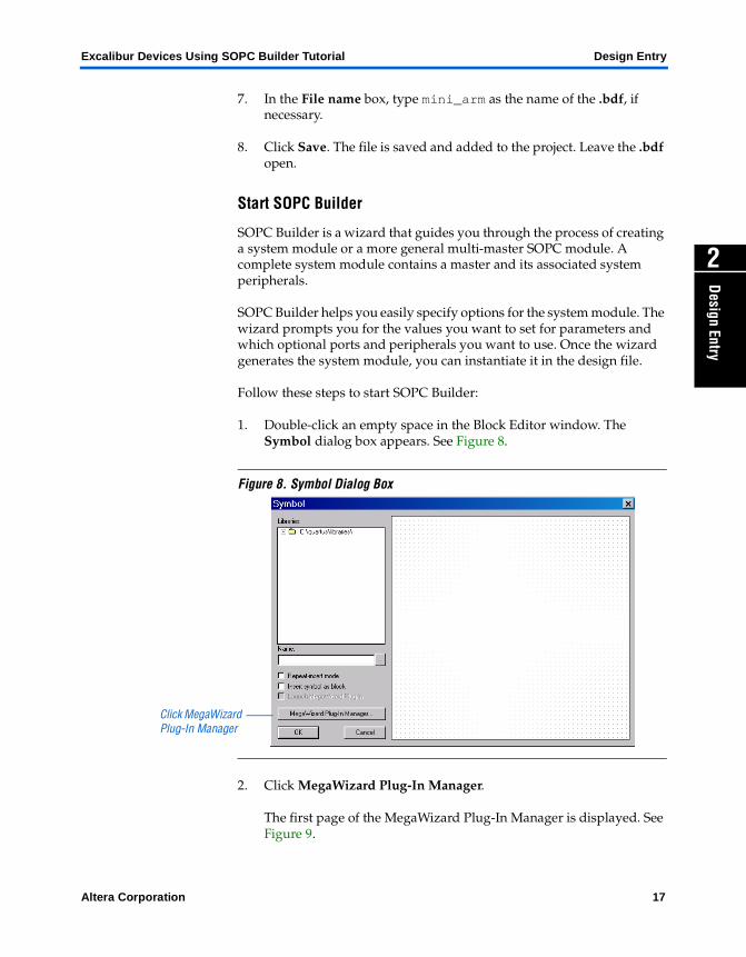
1. Double-click an empty space in the Block Editor window. The Symbol dialog box appears. See Figure 8.
Figure 8. Symbol Dialog Box
2. Click MegaWizard Plug-In Manager.
The first page of the MegaWizard Plug-In Manager is displayed. See Figure 9.
Click MegaWizard Plug-In Manager
Altera Corporation 17
Design Entry Excalibur Devices Using SOPC Builder Tutorial
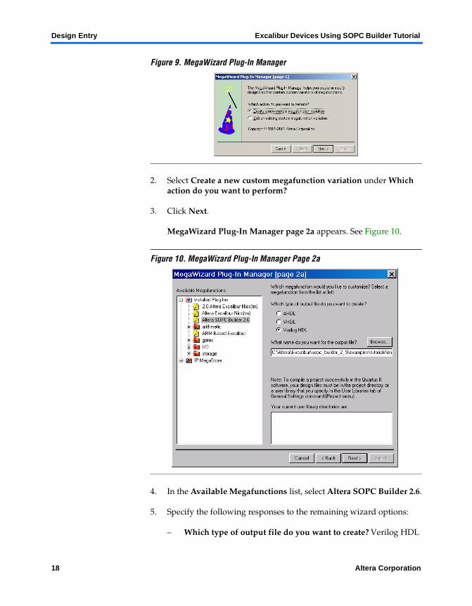
Figure 9. MegaWizard Plug-In Manager
2. Select Create a new custom megafunction variation under Which action do you want to perform?
3. Click Next.
MegaWizard Plug-In Manager page 2a appears. See Figure 10.
Figure 10. MegaWizard Plug-In Manager Page 2a
4. In the Available Megafunctions list, select Altera SOPC Builder 2.6.
5. Specify the following responses to the remaining wizard options:
– Which type of output file do you want to create? Verilog HDL
18 Altera Corporation
Excalibur Devices Using SOPC Builder Tutorial Design Entry
Design Entry
2
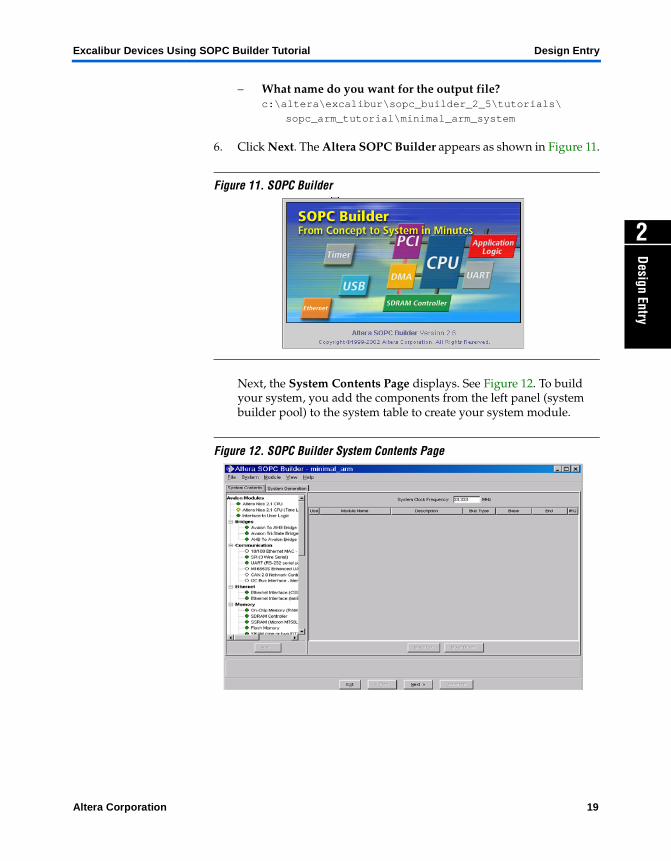
– What name do you want for the output file? c:\altera\excalibur\sopc_builder_2_5\tutorials\
sopc_arm_tutorial\minimal_arm_system
6. Click Next. The Altera SOPC Builder appears as shown in Figure 11.
Figure 11. SOPC Builder
Next, the System Contents Page displays. See Figure 12. To build your system, you add the components from the left panel (system builder pool) to the system table to create your system module.
Figure 12. SOPC Builder System Contents Page
Altera Corporation 19
Design Entry Excalibur Devices Using SOPC Builder Tutorial
Add CPU & Peripherals
The system peripherals allow the Excalibur device to connect and communicate with internal logic in the Excalibur device, or external hardware on the EPXA10 development board. Use the SOPC Builder to specify the name, type, memory map addresses, and interrupts of the system peripherals for your system module.
1 The following instructions ensure that the mini_arm design functions correctly on the EPXA10 development board, and allow you to run the software examples provided in your project’s software development kit (SDK) directory.
f See EPXA10 Development Board Hardware Reference Manual for more information about the Excalibur device board components.
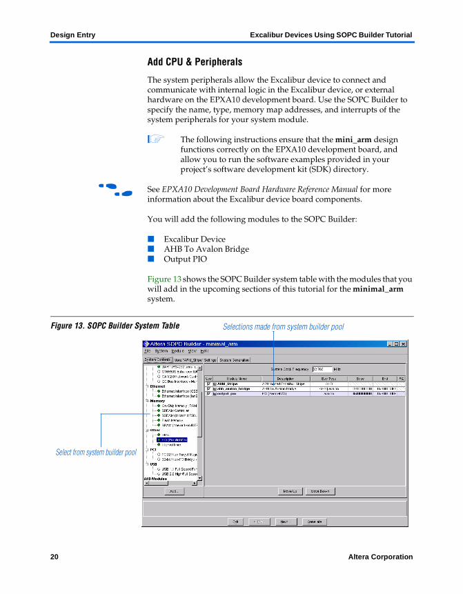
You will add the following modules to the SOPC Builder:
■ Excalibur Device■ AHB To Avalon Bridge■ Output PIO
Figure 13 shows the SOPC Builder system table with the modules that you will add in the upcoming sections of this tutorial for the minimal_arm system.
Figure 13. SOPC Builder System Table
Select from system builder pool
Selections made from system builder pool
20 Altera Corporation
Excalibur Devices Using SOPC Builder Tutorial Design Entry
Design Entry
2
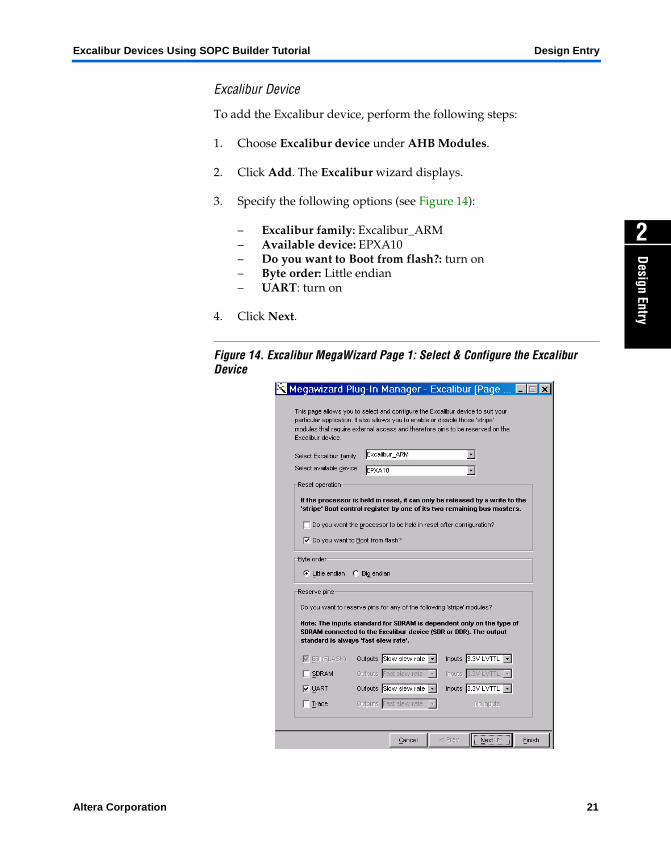
Excalibur Device
To add the Excalibur device, perform the following steps:
1. Choose Excalibur device under AHB Modules.
2. Click Add. The Excalibur wizard displays.
3. Specify the following options (see Figure 14):
– Excalibur family: Excalibur_ARM– Available device: EPXA10– Do you want to Boot from flash?: turn on– Byte order: Little endian– UART: turn on
4. Click Next.
Figure 14. Excalibur MegaWizard Page 1: Select & Configure the Excalibur Device
Altera Corporation 21
Design Entry Excalibur Devices Using SOPC Builder Tutorial
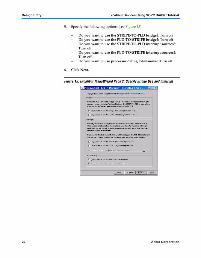
5. Specify the following options (see Figure 15):
– Do you want to use the STRIPE-TO-PLD bridge?: Turn on– Do you want to use the PLD-TO-STRIPE bridge?: Turn off – Do you want to use the STRIPE-TO-PLD interrupt sources?:
Turn off– Do you want to use the PLD-TO-STRIPE interrupt sources?:
Turn off– Do you want to use processor debug extensions?: Turn off
6. Click Next.
Figure 15. Excalibur MegaWizard Page 2: Specify Bridge Use and Interrupt
22 Altera Corporation
Excalibur Devices Using SOPC Builder Tutorial Design Entry
Design Entry
2
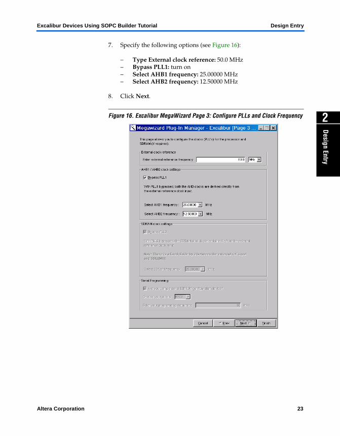
7. Specify the following options (see Figure 16):
– Type External clock reference: 50.0 MHz– Bypass PLL1: turn on– Select AHB1 frequency: 25.00000 MHz– Select AHB2 frequency: 12.50000 MHz
8. Click Next.
Figure 16. Excalibur MegaWizard Page 3: Configure PLLs and Clock Frequency
Altera Corporation 23
Design Entry Excalibur Devices Using SOPC Builder Tutorial
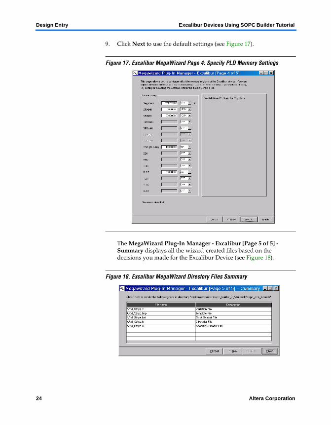
9. Click Next to use the default settings (see Figure 17).
Figure 17. Excalibur MegaWizard Page 4: Specify PLD Memory Settings
The MegaWizard Plug-In Manager - Excalibur [Page 5 of 5] - Summary displays all the wizard-created files based on the decisions you made for the Excalibur Device (see Figure 18).
Figure 18. Excalibur MegaWizard Directory Files Summary
24 Altera Corporation
Excalibur Devices Using SOPC Builder Tutorial Design Entry
Design Entry
2
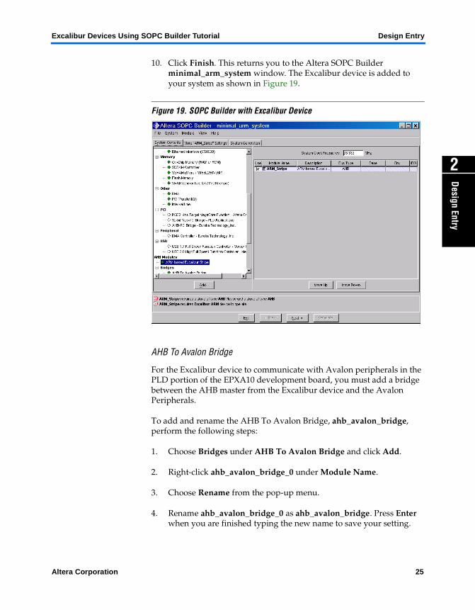
10. Click Finish. This returns you to the Altera SOPC Builder minimal_arm_system window. The Excalibur device is added to your system as shown in Figure 19.
Figure 19. SOPC Builder with Excalibur Device
AHB To Avalon Bridge
For the Excalibur device to communicate with Avalon peripherals in the PLD portion of the EPXA10 development board, you must add a bridge between the AHB master from the Excalibur device and the Avalon Peripherals.
To add and rename the AHB To Avalon Bridge, ahb_avalon_bridge, perform the following steps:
1. Choose Bridges under AHB To Avalon Bridge and click Add.
2. Right-click ahb_avalon_bridge_0 under Module Name.
3. Choose Rename from the pop-up menu.
4. Rename ahb_avalon_bridge_0 as ahb_avalon_bridge. Press Enter when you are finished typing the new name to save your setting.
Altera Corporation 25
Design Entry Excalibur Devices Using SOPC Builder Tutorial
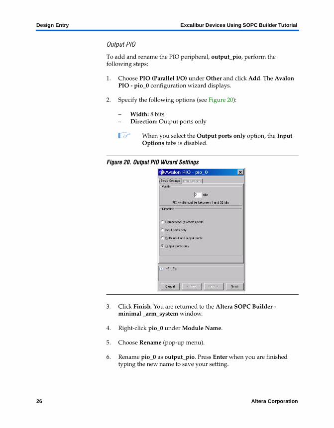
Output PIO
To add and rename the PIO peripheral, output_pio, perform the following steps:
1. Choose PIO (Parallel I/O) under Other and click Add. The Avalon PIO - pio_0 configuration wizard displays.
2. Specify the following options (see Figure 20):
– Width: 8 bits– Direction: Output ports only
1 When you select the Output ports only option, the Input Options tabs is disabled.
Figure 20. Output PIO Wizard Settings
3. Click Finish. You are returned to the Altera SOPC Builder - minimal _arm_system window.
4. Right-click pio_0 under Module Name.
5. Choose Rename (pop-up menu).
6. Rename pio_0 as output_pio. Press Enter when you are finished typing the new name to save your setting.
26 Altera Corporation
Excalibur Devices Using SOPC Builder Tutorial Design Entry
Design Entry
2
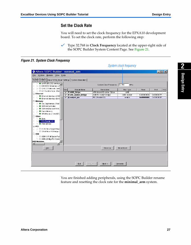
Set the Clock Rate
You will need to set the clock frequency for the EPXA10 development board. To set the clock rate, perform the following step:
v Type 32.768 in Clock Frequency located at the upper-right side of the SOPC Builder System Content Page. See Figure 21.
Figure 21. System Clock Frequency
You are finished adding peripherals, using the SOPC Builder rename feature and resetting the clock rate for the minimal_arm system.
System clock frequency
Altera Corporation 27
Design Entry Excalibur Devices Using SOPC Builder Tutorial
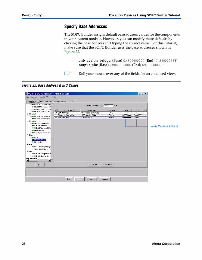
Specify Base Addresses
The SOPC Builder assigns default base address values for the components in your system module. However, you can modify these defaults by clicking the base address and typing the correct value. For this tutorial, make sure that the SOPC Builder uses the base addresses shown in Figure 22.
– ahb_avalon_bridge: (Base) 0x80000000 (End) 0x800003FF– output_pio: (Base) 0x80000000 (End) 0x8000000F
1 Roll your mouse over any of the fields for an enhanced view.
Figure 22. Base Address & IRQ Values
verify the base address
28 Altera Corporation
Excalibur Devices Using SOPC Builder Tutorial Design Entry
Design Entry
2
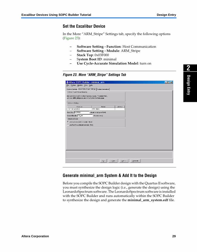
Set the Excalibur Device
In the More “ARM_Stripe” Settings tab, specify the following options (Figure 23):
– Software Setting - Function: Host Communication – Software Setting - Module: ARM_Stripe– Stack Top: 0x03F000– System Boot ID: minimal – Use Cycle-Accurate Simulation Model: turn on
Figure 23. More “ARM_Stripe” Settings Tab
Generate minimal_arm System & Add It to the Design
Before you compile the SOPC Builder design with the Quartus II software, you must synthesize the design logic (i.e., generate the design) using the LeonardoSpectrum software. The LeonardoSpectrum software is installed with the SOPC Builder and runs automatically within the SOPC Builder to synthesize the design and generate the minimal_arm_system.edf file.
Altera Corporation 29
Design Entry Excalibur Devices Using SOPC Builder Tutorial
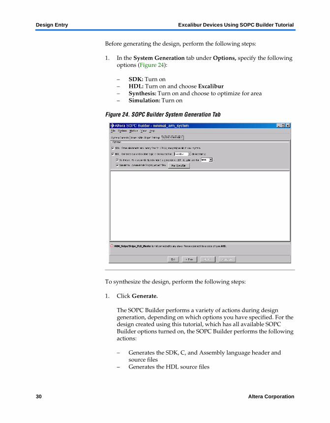
Before generating the design, perform the following steps:
1. In the System Generation tab under Options, specify the following options (Figure 24):
– SDK: Turn on– HDL: Turn on and choose Excalibur– Synthesis: Turn on and choose to optimize for area– Simulation: Turn on
Figure 24. SOPC Builder System Generation Tab
To synthesize the design, perform the following steps:
1. Click Generate.
The SOPC Builder performs a variety of actions during design generation, depending on which options you have specified. For the design created using this tutorial, which has all available SOPC Builder options turned on, the SOPC Builder performs the following actions:
– Generates the SDK, C, and Assembly language header and source files
– Generates the HDL source files
30 Altera Corporation
Excalibur Devices Using SOPC Builder Tutorial Design Entry
Design Entry
2
– Creates the simulation project and source files– Synthesizes the HDL files using the LeonardoSpectrum software
and produces an EDIF netlist file
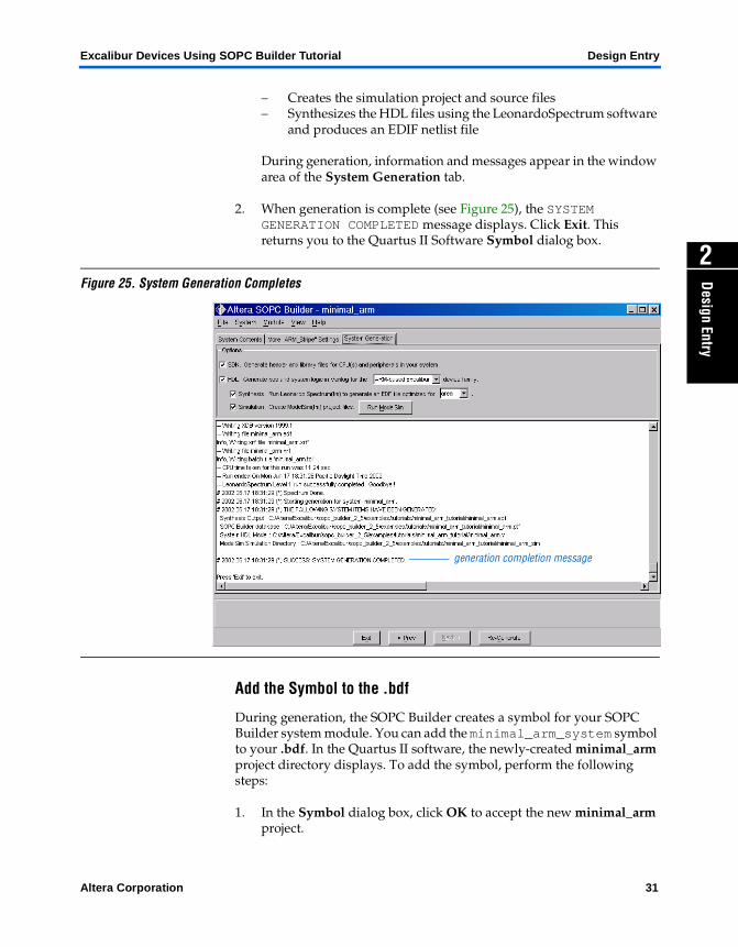
During generation, information and messages appear in the window area of the System Generation tab.
2. When generation is complete (see Figure 25), the SYSTEM GENERATION COMPLETED message displays. Click Exit. This returns you to the Quartus II Software Symbol dialog box.
Figure 25. System Generation Completes
Add the Symbol to the .bdf
During generation, the SOPC Builder creates a symbol for your SOPC Builder system module. You can add the minimal_arm_system symbol to your .bdf. In the Quartus II software, the newly-created minimal_arm project directory displays. To add the symbol, perform the following steps:
1. In the Symbol dialog box, click OK to accept the new minimal_arm project.
generation completion message
Altera Corporation 31
Design Entry Excalibur Devices Using SOPC Builder Tutorial
2. In the c:\altera\excalibur\sopc_builder_2_5\tutorials\sopc_arm_tutorial directory, select the newly created symbol, minimal_arm_system.bsf.
3. Click Open. A preview of the minimal_arm_system symbol appears in the Symbol dialog box.
4. The minimal_arm_system symbol graphic is attached to the pointer. Click OK to instantiate the minimal_arm_system symbol in the .bdf file.
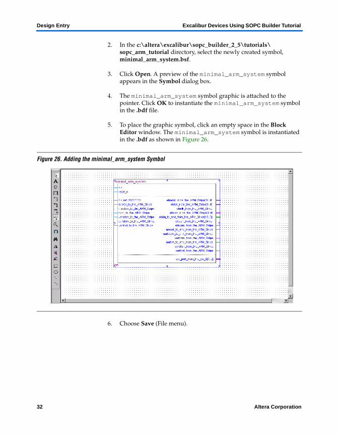
5. To place the graphic symbol, click an empty space in the Block Editor window. The minimal_arm_system symbol is instantiated in the .bdf as shown in Figure 26.
Figure 26. Adding the minimal_arm_system Symbol
6. Choose Save (File menu).
32 Altera Corporation
Excalibur Devices Using SOPC Builder Tutorial Design Entry
Design Entry
2
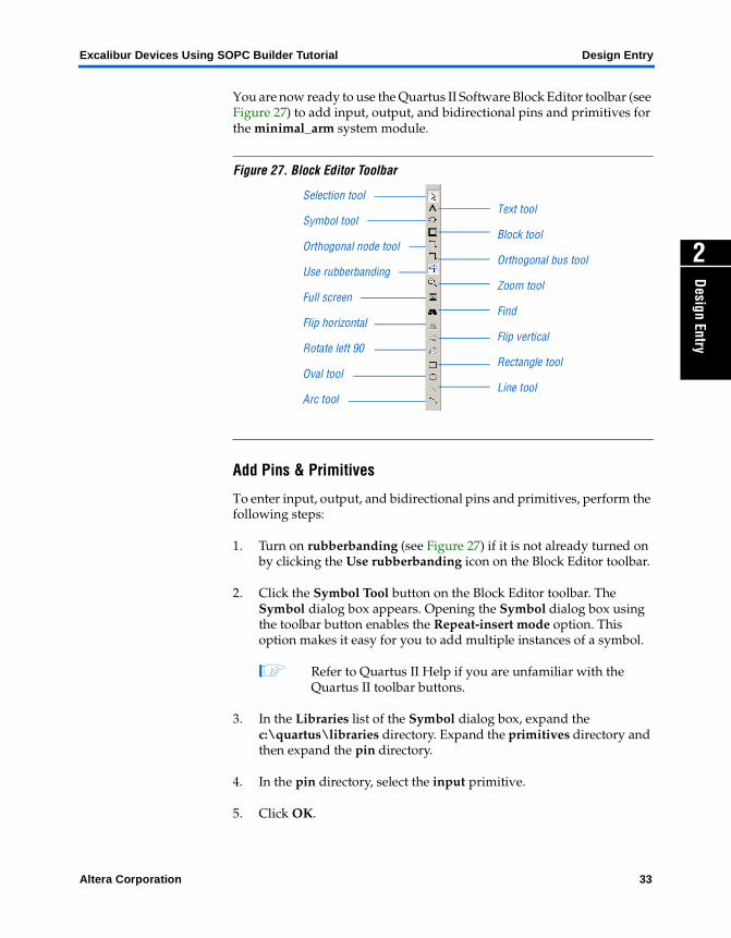
You are now ready to use the Quartus II Software Block Editor toolbar (see Figure 27) to add input, output, and bidirectional pins and primitives for the minimal_arm system module.
Figure 27. Block Editor Toolbar
Add Pins & Primitives
To enter input, output, and bidirectional pins and primitives, perform the following steps:
1. Turn on rubberbanding (see Figure 27) if it is not already turned on by clicking the Use rubberbanding icon on the Block Editor toolbar.
2. Click the Symbol Tool button on the Block Editor toolbar. The Symbol dialog box appears. Opening the Symbol dialog box using the toolbar button enables the Repeat-insert mode option. This option makes it easy for you to add multiple instances of a symbol.
1 Refer to Quartus II Help if you are unfamiliar with the Quartus II toolbar buttons.
3. In the Libraries list of the Symbol dialog box, expand the c:\quartus\libraries directory. Expand the primitives directory and then expand the pin directory.
4. In the pin directory, select the input primitive.
5. Click OK.
Selection tool
Symbol tool
Orthogonal node tool
Use rubberbanding
Full screen
Flip horizontal
Rotate left 90
Oval tool
Arc tool
Text tool
Block tool
Orthogonal bus tool
Zoom tool
Find
Flip vertical
Rectangle tool
Line tool
Altera Corporation 33
Design Entry Excalibur Devices Using SOPC Builder Tutorial
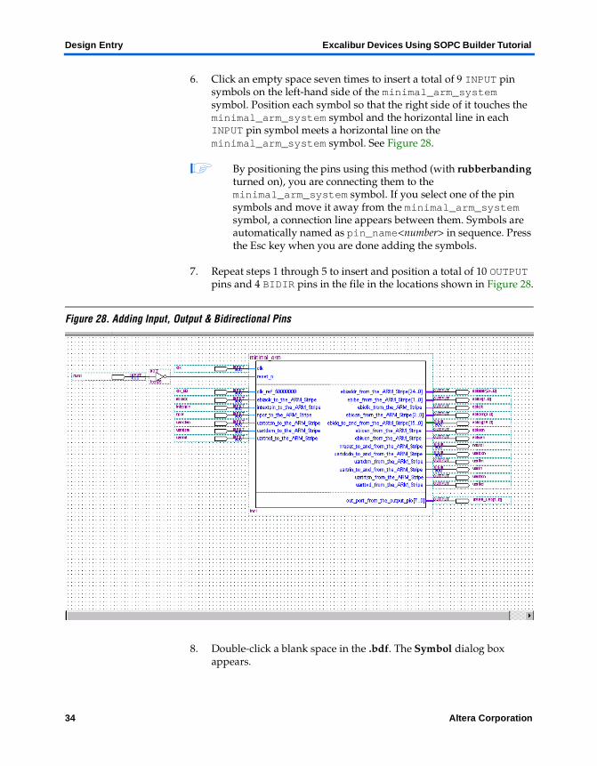
6. Click an empty space seven times to insert a total of 9 INPUT pin symbols on the left-hand side of the minimal_arm_system symbol. Position each symbol so that the right side of it touches the minimal_arm_system symbol and the horizontal line in each INPUT pin symbol meets a horizontal line on the minimal_arm_system symbol. See Figure 28.
1 By positioning the pins using this method (with rubberbanding turned on), you are connecting them to the minimal_arm_system symbol. If you select one of the pin symbols and move it away from the minimal_arm_system symbol, a connection line appears between them. Symbols are automatically named as pin_name<number> in sequence. Press the Esc key when you are done adding the symbols.
7. Repeat steps 1 through 5 to insert and position a total of 10 OUTPUT pins and 4 BIDIR pins in the file in the locations shown in Figure 28.
Figure 28. Adding Input, Output & Bidirectional Pins
8. Double-click a blank space in the .bdf. The Symbol dialog box appears.
34 Altera Corporation
Excalibur Devices Using SOPC Builder Tutorial Design Entry
Design Entry
2
9. In the Libraries list of the Symbol dialog box, expand the c:\quartus\libraries directory. Expand the primitives directory and then expand the logic directory.
10. In the logic directory, choose the not primitive.
11. Click OK.
12. Click an empty space in the .bdf next to the clk INPUT pin at the top left of the .bdf to insert the NOT symbol.
13. Choose Save (File menu).
Name the Pins
You can now name the pins. To name the clock pin, perform the following steps:
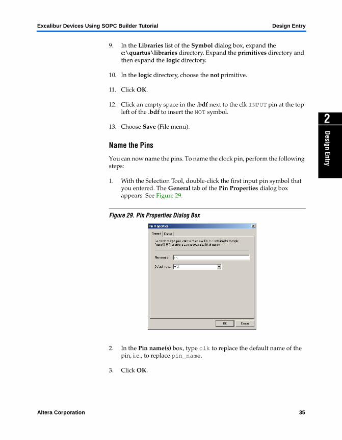
1. With the Selection Tool, double-click the first input pin symbol that you entered. The General tab of the Pin Properties dialog box appears. See Figure 29.
Figure 29. Pin Properties Dialog Box
2. In the Pin name(s) box, type clk to replace the default name of the pin, i.e., to replace pin_name.
3. Click OK.
Altera Corporation 35
Design Entry Excalibur Devices Using SOPC Builder Tutorial
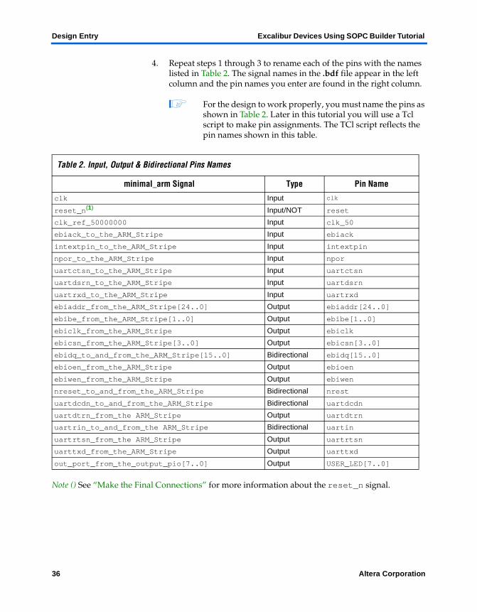
4. Repeat steps 1 through 3 to rename each of the pins with the names listed in Table 2. The signal names in the .bdf file appear in the left column and the pin names you enter are found in the right column.
1 For the design to work properly, you must name the pins as shown in Table 2. Later in this tutorial you will use a Tcl script to make pin assignments. The TCl script reflects the pin names shown in this table.
Note () See “Make the Final Connections” for more information about the reset_n signal.
Table 2. Input, Output & Bidirectional Pins Names
minimal_arm Signal Type Pin Name
clk Input clk
reset_n(1) Input/NOT reset
clk_ref_50000000 Input clk_50
ebiack_to_the_ARM_Stripe Input ebiack
intextpin_to_the_ARM_Stripe Input intextpin
npor_to_the_ARM_Stripe Input npor
uartctsn_to_the_ARM_Stripe Input uartctsn
uartdsrn_to_the_ARM_Stripe Input uartdsrn
uartrxd_to_the_ARM_Stripe Input uartrxd
ebiaddr_from_the_ARM_Stripe[24..0] Output ebiaddr[24..0]
ebibe_from_the_ARM_Stripe[1..0] Output ebibe[1..0]
ebiclk_from_the_ARM_Stripe Output ebiclk
ebicsn_from_the_ARM_Stripe[3..0] Output ebicsn[3..0]
ebidq_to_and_from_the_ARM_Stripe[15..0] Bidirectional ebidq[15..0]
ebioen_from_the_ARM_Stripe Output ebioen
ebiwen_from_the_ARM_Stripe Output ebiwen
nreset_to_and_from_the_ARM_Stripe Bidirectional nrest
uartdcdn_to_and_from_the_ARM_Stripe Bidirectional uartdcdn
uartdtrn_from_the ARM_Stripe Output uartdtrn
uartrin_to_and_from_the ARM_Stripe Bidirectional uartin
uartrtsn_from_the ARM_Stripe Output uartrtsn
uarttxd_from_the_ARM_Stripe Output uarttxd
out_port_from_the_output_pio[7..0] Output USER_LED[7..0]
36 Altera Corporation
Excalibur Devices Using SOPC Builder Tutorial Design Entry
Design Entry
2
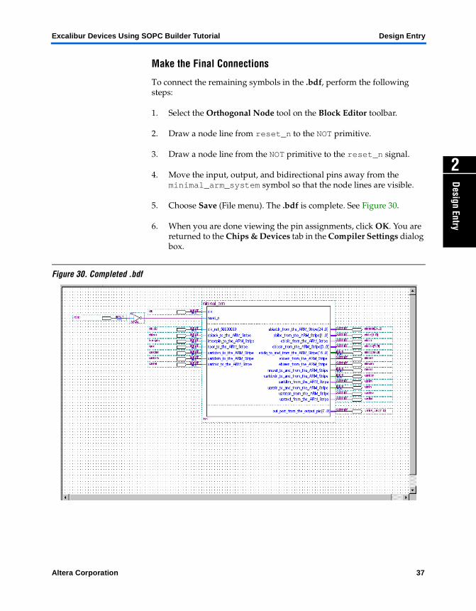
Make the Final Connections
To connect the remaining symbols in the .bdf, perform the following steps:
1. Select the Orthogonal Node tool on the Block Editor toolbar.
2. Draw a node line from reset_n to the NOT primitive.
3. Draw a node line from the NOT primitive to the reset_n signal.
4. Move the input, output, and bidirectional pins away from the minimal_arm_system symbol so that the node lines are visible.
5. Choose Save (File menu). The .bdf is complete. See Figure 30.
6. When you are done viewing the pin assignments, click OK. You are returned to the Chips & Devices tab in the Compiler Settings dialog box.
Figure 30. Completed .bdf
Altera Corporation 37

Altera Corporation
Compilation
Compilation
3
The Quartus II compiler consists of a series of modules that check a design for errors, synthesize the logic, fit the design into an Altera device, and generate output files for simulation, timing analysis, and device programming.
The following tutorial sections guide you through the steps necessary to create compiler settings, assign signals to device pins, specify EDA tool settings, and compile the design. The compilation tutorial sections include:
1. “Create Compiler Settings” on page 39
2. “Assign Signals to Device Pins” on page 42
3. “Specify Device, Programming & EDA Tool Settings” on page 44
4. “Compile the Design” on page 48
Create Compiler Settings
You can create compiler settings to control the compilation process. The compiler settings specify the compilation focus, the type of compilation to perform, the device to target, and other options. This section includes the following steps:
1. “View the Compiler General Settings” on page 40
2. “Specify the Device Family & Device” on page 40
1 The procedures below explain how to view and edit compiler settings using menu commands and dialog boxes. However, you can also easily specify compiler settings by following the steps in the Compiler Settings Wizard (Processing menu).
39
Compilation Excalibur Devices Using SOPC Builder Tutorial
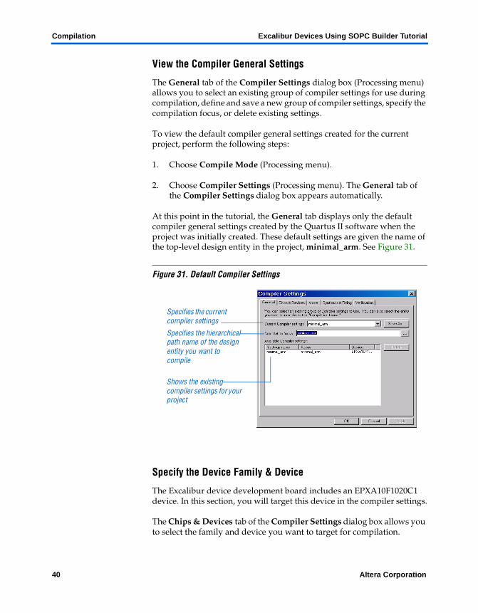
View the Compiler General Settings
The General tab of the Compiler Settings dialog box (Processing menu) allows you to select an existing group of compiler settings for use during compilation, define and save a new group of compiler settings, specify the compilation focus, or delete existing settings.
To view the default compiler general settings created for the current project, perform the following steps:
1. Choose Compile Mode (Processing menu).
2. Choose Compiler Settings (Processing menu). The General tab of the Compiler Settings dialog box appears automatically.
At this point in the tutorial, the General tab displays only the default compiler general settings created by the Quartus II software when the project was initially created. These default settings are given the name of the top-level design entity in the project, minimal_arm. See Figure 31.
Figure 31. Default Compiler Settings
Specify the Device Family & Device
The Excalibur device development board includes an EPXA10F1020C1 device. In this section, you will target this device in the compiler settings.
The Chips & Devices tab of the Compiler Settings dialog box allows you to select the family and device you want to target for compilation.
Shows the existing compiler settings for your project
Specifies the hierarchical path name of the design entity you want to compile
Specifies the current compiler settings
40 Altera Corporation
Excalibur Devices Using SOPC Builder Tutorial Compilation
Compilation
3
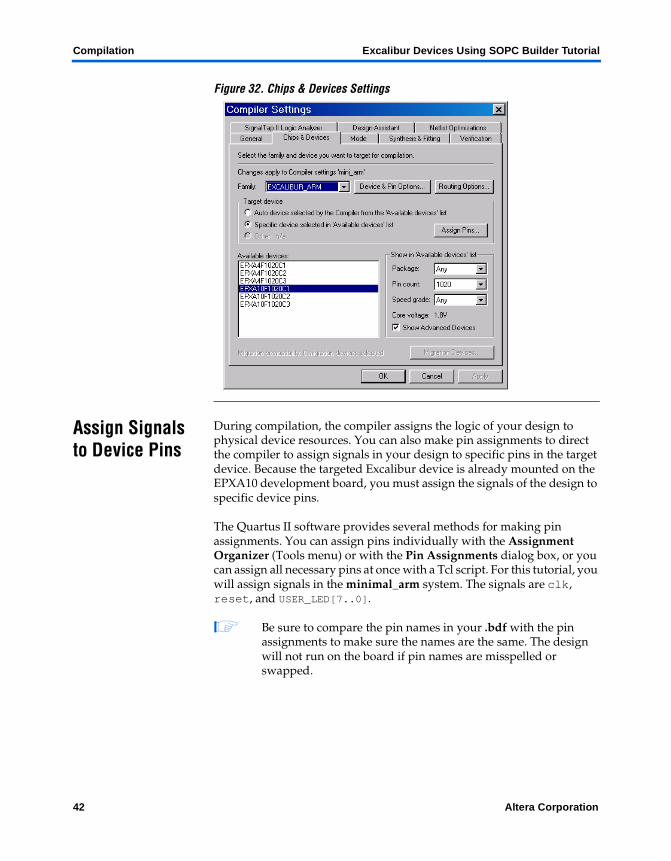
To select the device family and device, follow these steps:
1. In the Compiler Settings dialog box, click the Chips & Devices tab (see Figure 32).
2. In the Family list, choose EXCALIBUR_ARM.
3. If you receive a message that asks if you want the Quartus II software to choose a device automatically, click No.
4. Under Target device, select Specific device selected in ’Available devices’ list.
5. In the Available devices list, choose EPXA10F1020C1.
6. Under Show in ’Available devices’ list, verify the following options:
– Package: Any– Pin count: 1020– Speed grade: Any
1 As you change these options from Any, the number of available device listed decreases, making it easier for you to find your target device.
Altera Corporation 41
Compilation Excalibur Devices Using SOPC Builder Tutorial
Figure 32. Chips & Devices Settings
Assign Signals to Device Pins
During compilation, the compiler assigns the logic of your design to physical device resources. You can also make pin assignments to direct the compiler to assign signals in your design to specific pins in the target device. Because the targeted Excalibur device is already mounted on the EPXA10 development board, you must assign the signals of the design to specific device pins.
The Quartus II software provides several methods for making pin assignments. You can assign pins individually with the Assignment Organizer (Tools menu) or with the Pin Assignments dialog box, or you can assign all necessary pins at once with a Tcl script. For this tutorial, you will assign signals in the minimal_arm system. The signals are clk, reset, and USER_LED[7..0].
1 Be sure to compare the pin names in your .bdf with the pin assignments to make sure the names are the same. The design will not run on the board if pin names are misspelled or swapped.
42 Altera Corporation
Excalibur Devices Using SOPC Builder Tutorial Compilation
Compilation
3
This session includes the following steps:
1. “Reassign Pins” on page 43
2. “Click OK when you are finished adding pin names. This returns you to the Chips & Device tab in the Compiler Settings dialog box.” on page 44
3. “Reserve Unused Pins” on page 44
Reassign Pins
To reassign the clk, reset, and USER_LED[7..0]signals in the minimal_arm system, perform the following steps:
1. Choose Compiler Settings (Processing menu). The General tab of the Compiler Settings dialog box appears automatically.
2. Click the Chips & Devices tab.
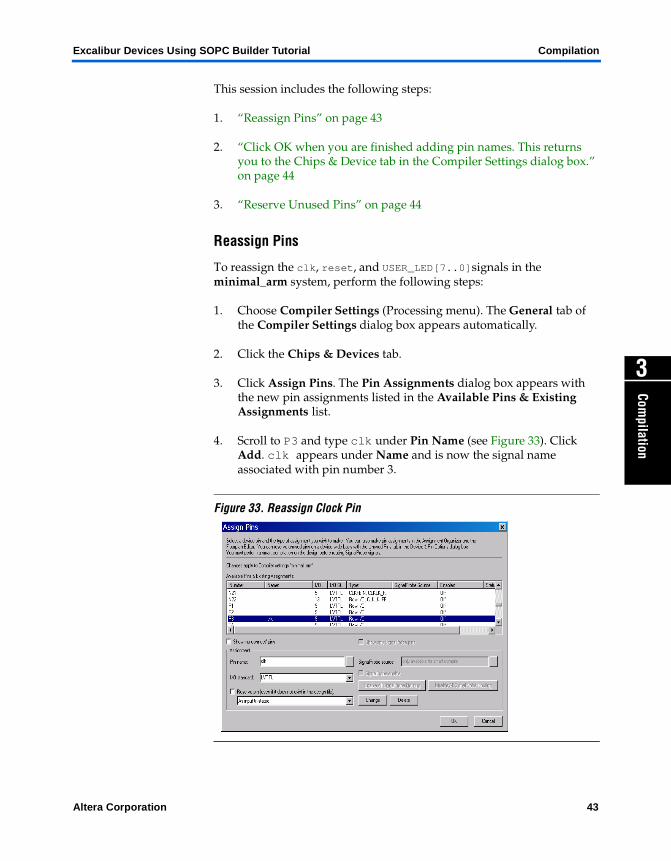
3. Click Assign Pins. The Pin Assignments dialog box appears with the new pin assignments listed in the Available Pins & Existing Assignments list.
4. Scroll to P3 and type clk under Pin Name (see Figure 33). Click Add. clk appears under Name and is now the signal name associated with pin number 3.
Figure 33. Reassign Clock Pin
Altera Corporation 43
Compilation Excalibur Devices Using SOPC Builder Tutorial
5. Scroll to T8 and type reset under Pin Name. Click Add.
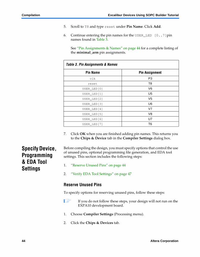
6. Continue entering the pin names for the USER_LED [0..7]pin names found in Table 3.
See “Pin Assignments & Names” on page 44 for a complete listing of the minimal_arm pin assignments.
7. Click OK when you are finished adding pin names. This returns you to the Chips & Device tab in the Compiler Settings dialog box.
Specify Device, Programming & EDA Tool Settings
Before compiling the design, you must specify options that control the use of unused pins, optional programming file generation, and EDA tool settings. This section includes the following steps:
1. “Reserve Unused Pins” on page 44
2. “Verify EDA Tool Settings” on page 47
Reserve Unused Pins
To specify options for reserving unused pins, follow these steps:
1 If you do not follow these steps, your design will not run on the EXPA10 development board.
1. Choose Compiler Settings (Processing menu).
2. Click the Chips & Devices tab.
Table 3. Pin Assignments & Names
Pin Name Pin Assignment
clk P3
reset T8
USER_LED[0] V6
USER_LED[1] U5
USER_LED[2] V5
USER_LED[3] U6
USER_LED[4] V7
USER_LED[5] V8
USER_LED[6] U7
USER_LED[7] T6
44 Altera Corporation
Excalibur Devices Using SOPC Builder Tutorial Compilation
Compilation
3
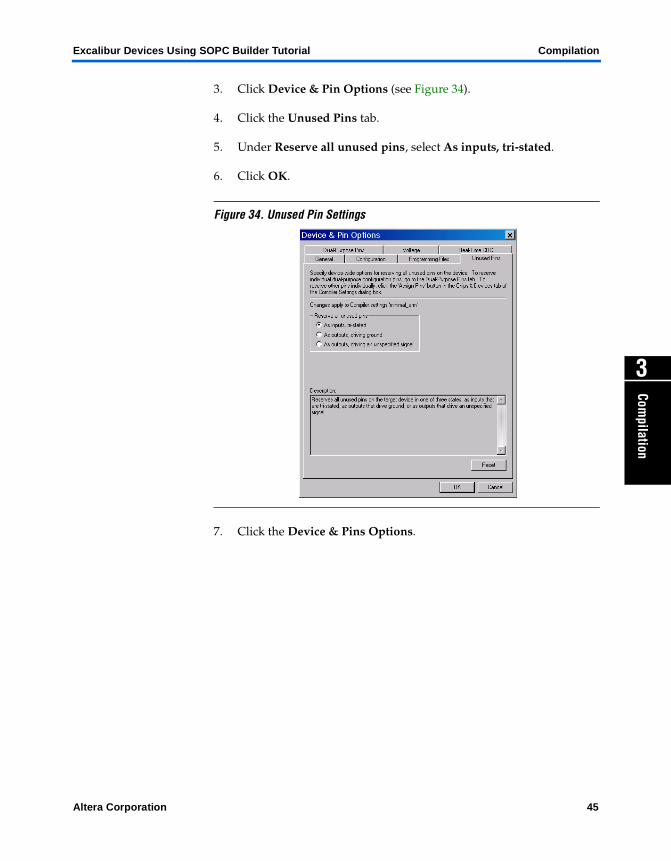
3. Click Device & Pin Options (see Figure 34).
4. Click the Unused Pins tab.
5. Under Reserve all unused pins, select As inputs, tri-stated.
6. Click OK.
Figure 34. Unused Pin Settings
7. Click the Device & Pins Options.
Altera Corporation 45
Compilation Excalibur Devices Using SOPC Builder Tutorial
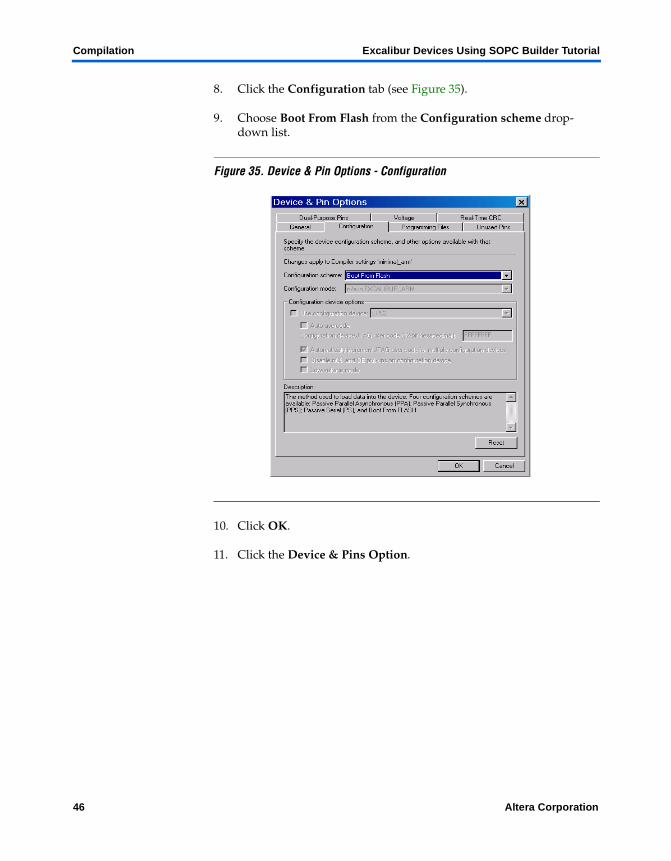
8. Click the Configuration tab (see Figure 35).
9. Choose Boot From Flash from the Configuration scheme drop-down list.
Figure 35. Device & Pin Options - Configuration
10. Click OK.
11. Click the Device & Pins Option.
46 Altera Corporation
Excalibur Devices Using SOPC Builder Tutorial Compilation
Compilation
3
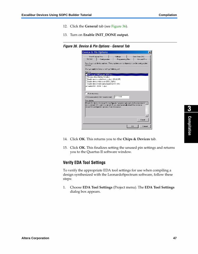
12. Click the General tab (see Figure 36).
13. Turn on Enable INIT_DONE output.
Figure 36. Device & Pin Options - General Tab
14. Click OK. This returns you to the Chips & Devices tab.
15. Click OK. This finalizes setting the unused pin settings and returns you to the Quartus II software window.
Verify EDA Tool Settings
To verify the appropriate EDA tool settings for use when compiling a design synthesized with the LeonardoSpectrum software, follow these steps:
1. Choose EDA Tool Settings (Project menu). The EDA Tool Settings dialog box appears.
Altera Corporation 47
Compilation Excalibur Devices Using SOPC Builder Tutorial
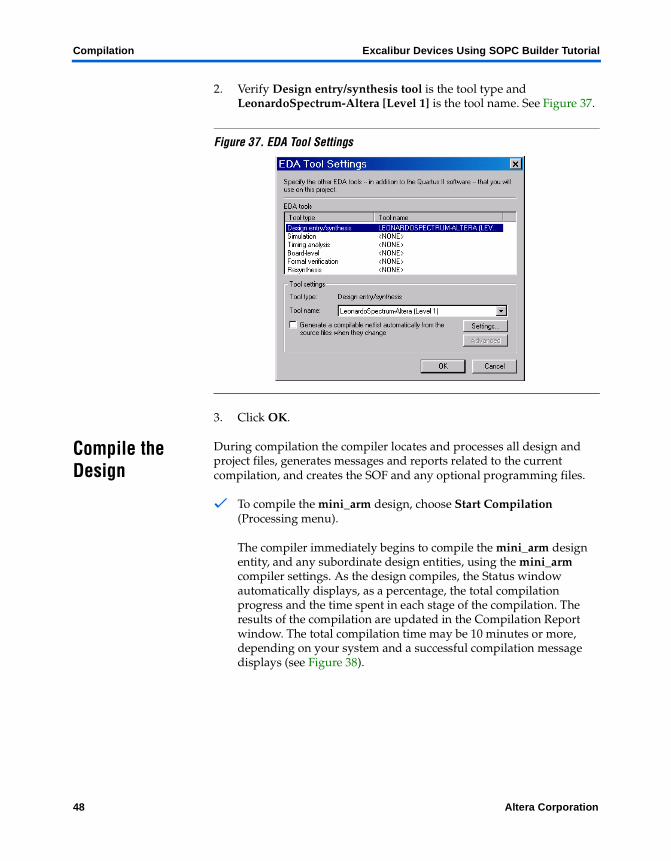
2. Verify Design entry/synthesis tool is the tool type and LeonardoSpectrum-Altera [Level 1] is the tool name. See Figure 37.
Figure 37. EDA Tool Settings
3. Click OK.
Compile the Design
During compilation the compiler locates and processes all design and project files, generates messages and reports related to the current compilation, and creates the SOF and any optional programming files.
v To compile the mini_arm design, choose Start Compilation (Processing menu).
The compiler immediately begins to compile the mini_arm design entity, and any subordinate design entities, using the mini_arm compiler settings. As the design compiles, the Status window automatically displays, as a percentage, the total compilation progress and the time spent in each stage of the compilation. The results of the compilation are updated in the Compilation Report window. The total compilation time may be 10 minutes or more, depending on your system and a successful compilation message displays (see Figure 38).
48 Altera Corporation
Excalibur Devices Using SOPC Builder Tutorial Compilation
Compilation
3
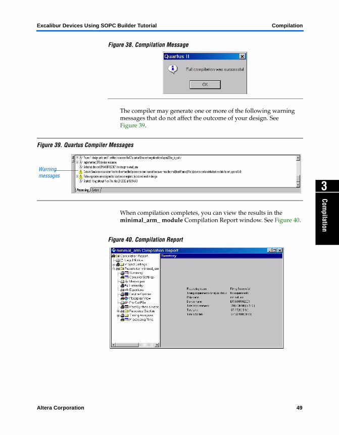
Figure 38. Compilation Message
The compiler may generate one or more of the following warning messages that do not affect the outcome of your design. See Figure 39.
Figure 39. Quartus Compiler Messages
When compilation completes, you can view the results in the minimal_arm_ module Compilation Report window. See Figure 40.
Figure 40. Compilation Report
Warning messages
Altera Corporation 49

Compilation Excalibur Devices Using SOPC Builder Tutorial
If the compiler displays any error messages, you should correct them in your design and recompile it until it is error-free before proceeding with the tutorial.
1 Verify that all the pin assignments are correct. This is a common error causing compilation errors.
You can select the message and choose Locate (right button pop-up menu) to find its source(s), and/or choose Help (right button pop-up menu) to display help on the message. Refer to the Compilation module in the Quartus II on-line tutorial for more information about viewing compilation results
.
50 Altera Corporation

Altera Corporation
Programming
4
Programm
ingProgram
ming
4
You have already completed creating and instantiating the minimal_arm system. This chapter guides you thorough the steps in SOPC Builder for creating the software build to simulate C code running on the EPXA10 development board and download the software to the EXPA10 development board.
Software Build To create the software build, you will add the software files, select software build settings, establish the linking of the files and simulate your minimal_arm project. In this section you will set up the Quartus II software to compile the assembly program. The various assembler and linker options will be set to produce a .hex file.
Add Software Files
To add the software files to your project, perform the following steps:
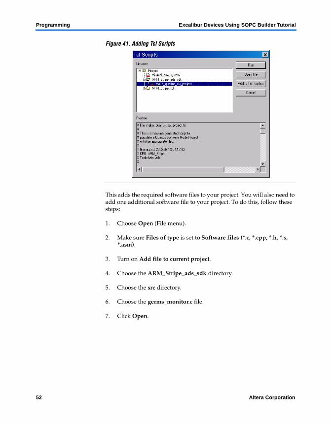
1. Choose Tcl Scripts (Tools Menu). See Figure 41.
2. Choose Project under Libraries.
3. Choose ARM_Stripe_ads_sdk.
4. Choose Make_quartus_sw_project.
5. Click Run.
51
Programming Excalibur Devices Using SOPC Builder Tutorial
Figure 41. Adding Tcl Scripts
This adds the required software files to your project. You will also need to add one additional software file to your project. To do this, follow these steps:
1. Choose Open (File menu).
2. Make sure Files of type is set to Software files (*.c, *.cpp, *.h, *.s, *.asm).
3. Turn on Add file to current project.
4. Choose the ARM_Stripe_ads_sdk directory.
5. Choose the src directory.
6. Choose the germs_monitor.c file.
7. Click Open.
52 Altera Corporation
Excalibur Devices Using SOPC Builder Tutorial Programming
Programm
ing
4
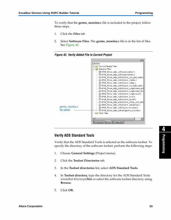
To verify that the germs_monitor.c file is included in the project, follow these steps.
1. Click the Files tab.
2. Select Software Files. The germs_monitor.c file is in the list of files. See Figure 42.
Figure 42. Verify Added File to Current Project
Verify ADS Standard Tools
Verify that the ADS Standard Tools is selected as the software toolset. To specify the directory of the software toolset, perform the following steps:
1. Choose General Settings (Project menu).
2. Click the Toolset Directories tab.
3. In the Toolset directories list, select ADS Standard Tools.
4. In Toolset directory, type the directory for the ADS Standard Tools <installed directory>/bin or select the software toolset directory using Browse.
5. Click OK.
germs_monitor.c file added
Altera Corporation 53
Programming Excalibur Devices Using SOPC Builder Tutorial
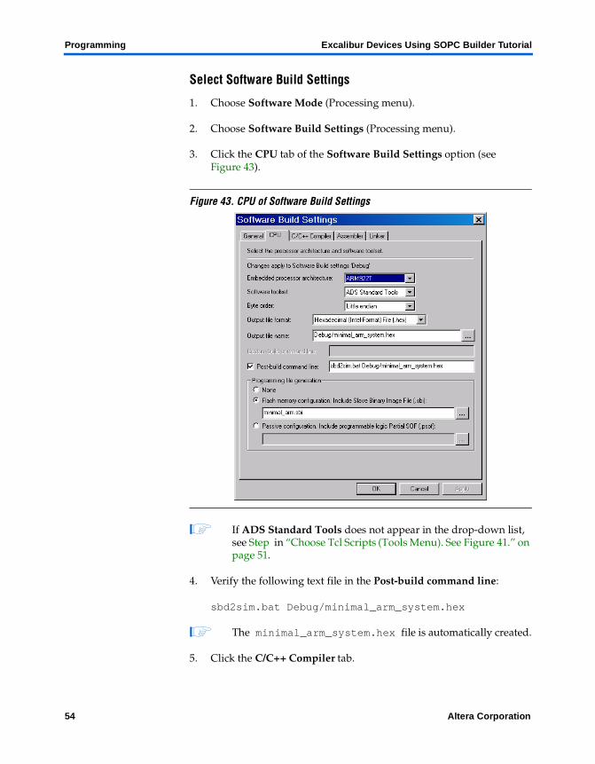
Select Software Build Settings
1. Choose Software Mode (Processing menu).
2. Choose Software Build Settings (Processing menu).
3. Click the CPU tab of the Software Build Settings option (see Figure 43).
Figure 43. CPU of Software Build Settings
1 If ADS Standard Tools does not appear in the drop-down list, see Step in “Choose Tcl Scripts (Tools Menu). See Figure 41.” on page 51.
4. Verify the following text file in the Post-build command line:
sbd2sim.bat Debug/minimal_arm_system.hex
1 The minimal_arm_system.hex file is automatically created.
5. Click the C/C++ Compiler tab.
54 Altera Corporation
Excalibur Devices Using SOPC Builder Tutorial Programming
Programm
ing
4
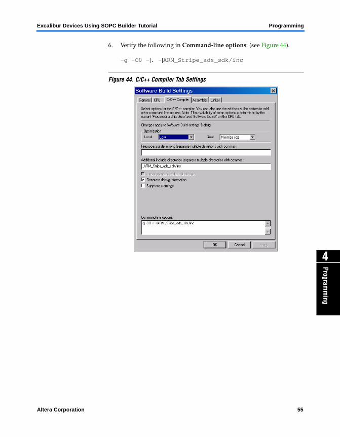
6. Verify the following in Command-line options: (see Figure 44).
-g -O0 -|. -|ARM_Stripe_ads_sdk/inc
Figure 44. C/C++ Compiler Tab Settings
Altera Corporation 55
Programming Excalibur Devices Using SOPC Builder Tutorial
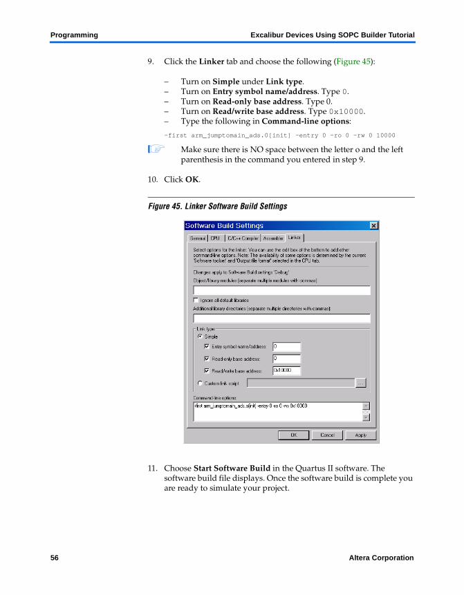
9. Click the Linker tab and choose the following (Figure 45):
– Turn on Simple under Link type.– Turn on Entry symbol name/address. Type 0.– Turn on Read-only base address. Type 0. – Turn on Read/write base address. Type 0x10000.– Type the following in Command-line options:
-first arm_jumptomain_ads.0[init] -entry 0 -ro 0 -rw 0 10000
1 Make sure there is NO space between the letter o and the left parenthesis in the command you entered in step 9.
10. Click OK.
Figure 45. Linker Software Build Settings
11. Choose Start Software Build in the Quartus II software. The software build file displays. Once the software build is complete you are ready to simulate your project.
56 Altera Corporation
Excalibur Devices Using SOPC Builder Tutorial Programming
Programm
ing
4
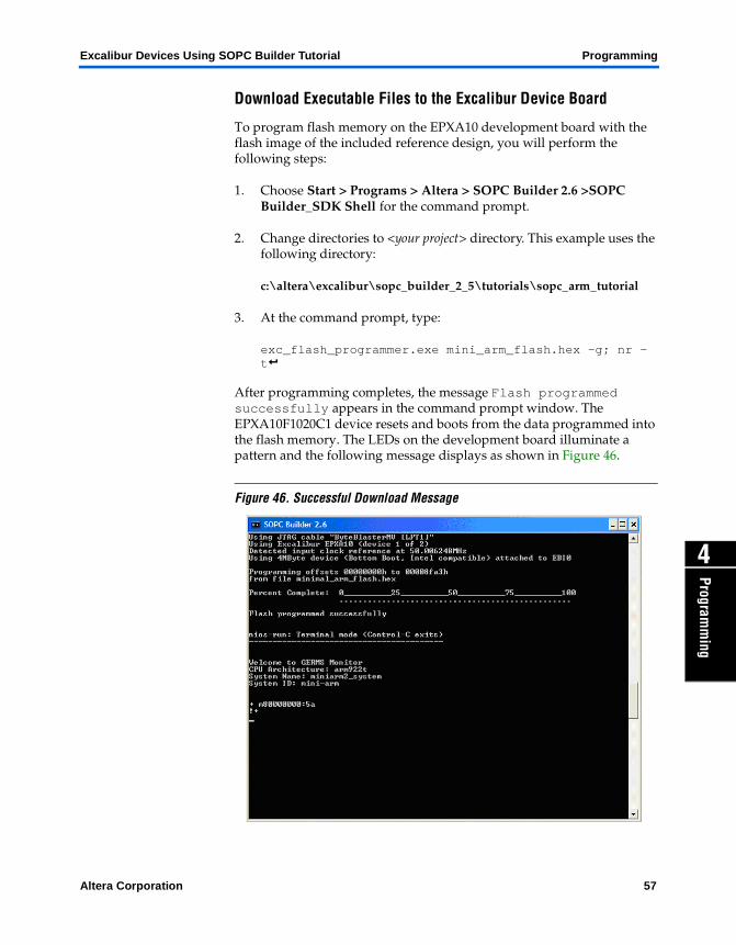
Download Executable Files to the Excalibur Device Board
To program flash memory on the EPXA10 development board with the flash image of the included reference design, you will perform the following steps:
1. Choose Start > Programs > Altera > SOPC Builder 2.6 >SOPC Builder_SDK Shell for the command prompt.
2. Change directories to <your project> directory. This example uses the following directory:
c:\altera\excalibur\sopc_builder_2_5\tutorials\sopc_arm_tutorial
3. At the command prompt, type:
exc_flash_programmer.exe mini_arm_flash.hex -g; nr -tr
After programming completes, the message Flash programmed successfully appears in the command prompt window. The EPXA10F1020C1 device resets and boots from the data programmed into the flash memory. The LEDs on the development board illuminate a pattern and the following message displays as shown in Figure 46.
Figure 46. Successful Download Message
Altera Corporation 57

Programming Excalibur Devices Using SOPC Builder Tutorial
Next Steps Congratulations! You have finished creating, verifying and using the SOPC Builder minimal_arm system module.
See the Altera literature page for more information about SOPC Builder, the Excalibur device, and the EPXA10 development board at http://www.altera.com/literature/lit-index.html.
58 Altera Corporation