Embed Size (px)
Citation preview

Chapter 3: Hardware and Software Codesign Flow
3.1 Introduction to Nios II Soft-Core Processor
1) Introduction to the Altera Nios II Soft Processor: <system cd>\DE2_115_tutorials\tut_nios2_introduction.pdf
• focus: All of the information in this resource is needed for creating systems and should be read carefully, as familiarity will greatly help students in avoiding time consuming mistakes. Nios II is an embedded processor architecture designed specifically for Altera’s FPGA boards. An example of a Nios II processor system could be found on page 11 from Altera’s Nios II Processor Reference Handbook. When implementing your board there is three different types of CPU’s to choose from which are the NIOS II/fast, NIOS II/standard, and NIOS II/economy. The main differences between the CPU’s are the balance between performance and cost.
NOTE: This figure taken from Altera’s Nios II Processor Reference Handbook: http://www.altera.com/literature/hb/nios2/n2cpu_nii5v1.pdf page 11

NOTE: This figure taken from Altera’s Nios II Processor Reference Handbook: http://www.altera.com/literature/hb/nios2/n2cpu_nii5v1.pdf page 18
2) Nios II Hardware Development: http://www.altera.com/literature/tt/tt_nios2_hardware_tutorial.pdf
• focus: This resource is an excellent overview of the basic requirements to creating a system using QSys in Quartus II, instantiating the design in the project files, implementation, and then creating the necessary software. 3) Nios II Processor Reference: http://www.altera.com/literature/hb/nios2/n2cpu_nii5v1.pdf
• NOTE: This resource has a lot of detailed information which is not necessary to complete most projects, but it is good to be familiar with document in the case of troubleshooting.

3.2 Code sign Flow
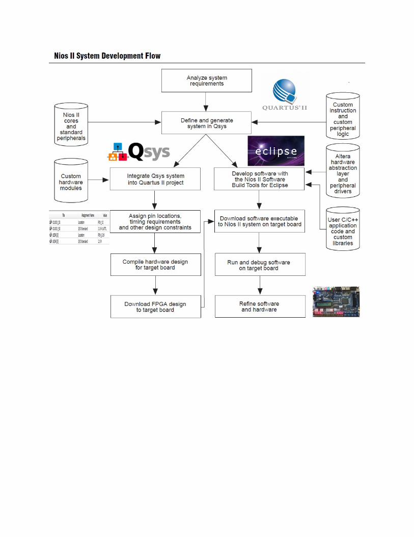
Figure 1–2 shows the Nios II system development flow between hardware and software. This flow consists of three types of development: hardware design steps, software design steps, and system design steps. NOTE: This figure taken from Altera’s Nios II Hardware Development Tutorial: http://www.altera.com/literature/tt/tt_nios2_hardware_tutorial.pdf
3.3 Overview of System Integration Software SOPC Builder and QSys
NOTE: This diagram was taken from Altera’s Nios II Software Developer’s Handbook, http://www.altera.com/literature/hb/nios2/n2sw_nii5v2.pdf
System Integration Software This software allows the designer to marry hardware and software. In order to use the Nios II soft-core processor, a system must be designed using either SOPC builder or QSys (both are accessed from Quartus II-> Menu -> Tools). QSys is a newer version of SOPC builder and it is encouraged that students begin with QSys. This development tool primarily generates the .sopcinfo file which is used in Nios II SBT for Eclipse to create the software project to run on top of the FPGA design, utilizing the Nios II soft-core processor. After creating a system to suit the students’ project needs, “Generation” (synonymous to “Compilation”) automatically creates the necessary hardware files for low-level abstraction. A main niosII module is created in this process, which is instantiated from the top-level hardware file. This process is described as System Integration Although much of the reading presented here applies to SOPC Builder, the information applies also to QSys and an effort should be made to use QSys in place of SOPC Builder.
1) Introduction to the Altera SOPC Builder: <system cd>\DE2_115_tutorials\tut_sopc_introduction_verilog.pdf 2) QSys System Design: http://www.altera.com/literature/tt/tt_qsys_intro.pdf
• QSys main reference page: http://www.altera.com/products/software/quartus-ii/subscription-edition/qsys/qts-qsys.html?GSA_pos=10&WT.oss_r=1&WT.oss=qSys 3) SOPC Builder User Guide: http://www.altera.com/literature/ug/ug_sopc_builder.pdf
3.4 Introduction to Nios II SBT for Eclipse
Eclipse allows the user to use the software that was executed by a Nios II processor-
based system in an FPGA. The user can configure the FPGA on the development board with the pre-generated Nios II standard hardware system by downloading the FPGA configuration file to the board.
1) Nios II Software Developer’s Handbook: http://www.altera.com/literature/hb/nios2/n2sw_nii5v2.pdf
NOTE: Link is placed here for reference, but is not necessary for review in this stage.

Binary Adder Tutorial Using Nios II {Includes video and written instructions}
A link to the video describing the Binary Adder Tutorial:
http://www.youtube.com/watch?v=307zpB2Y_UA&feature=channel_video_title
http://www.youtube.com/watch?v=6ATrkRqraJY&feature=channel_video_title
The major steps were:
1) Create hardware system in system builder
2) Build new system in QSys system
3) Instantiate the Nios II module in top level entity
4) Add IP variation file
5) Adjust .sdc
6) Place design on FPGA
7) Develop Software in Nios II SBT for Eclipse.
Hardware: Clock Red LEDs Switches 7 segment Hex LCD
NIOS II Binary Adder
Step 1: System Builder
1) Open DE2_115_tools->DE2_115_system_builder to find DE2_115_SystemBuilder.exe 2) Name the project under Project Name: Binary_Adder_Nios
3) Check all Components that you will be using: in this Tutorial we are using CLOCK,
LEDx27, 7-Segementx8, Switchx18, and of course the LCD.

4) Click Generate 5) Create a directory for your project and then click save
6) To open this project open the .qpf file
Step 2: Building Qsys System
1) Open Qsys under tools tab 2) Start by adding a Nios II Processor Core: Under “Component Library”-> Processors ->
Nios II Processor -> Add a. Select “Nios II/s” b. Set “Hardware multiplication type” = “None” c. Disable “Hardware divide” d. “Finish” e. Rename Nios to “cpu”
3) On-Chip Memory: Under “Component Library”-> Memories and Memory Controllers -> On-Chip -> On-Chip Memory (RAM or ROM)-> Click “Add”
a. Block Type list = “Auto” b. Total Memory size = “204800” to specify 2KB of memory c. Do not change any other default settings. d. “Finish” e. Under the “System Contents” tab, right-click the on-chip memory and rename as
“onchip_mem”

4) JTAG UART: Component Library -> Interface Protocols -> Serial -> JTAG UART -> Add
a. Do not change any default settings b. Rename to “jtag_uart”
5) Interval Timer: Component Library -> Peripherals -> Microcontroller Peripherals -> Interval Timer-> Add
a. Under “Hardware Options” set “Presets” to “Full-Featured” b. Do not change any other default settings c. Rename to “sys_clk_timer”
6) System ID Peripheral: Component Library-> Peripherals -> Debug and Performance -> System ID Peripheral-> Add
a. Do not change any default settings b. Rename as “sysid”
7) PIO’s: Component Library-> Peripherals -> Microcontroller Peripherals -> PIO -> Add a. Under “Basic Settings” enter the value of “4” for the box labeled “Width” b. Do not change any other default settings c. Finish d. Rename as “pio_led” e. For this example us two “pio_led” f. Repeat these steps for two “pio_sw” with 4 bits of width and change to input. g. Repeat these steps for pio_hex0 through 7 with widths of 7 bits.
8) LCD: Component Library-> Peripherals -> Display-> Character LCD -> Add a. Finish
9) Go to the “Connections” column and connect the following ports: (Figure Below) a. For all the components connect the clock input and outputs to clock_50 b. For all the components connect the Avalon memory mapped slave to the On-chip
memory AMMS. c. Open the Nios II processor named CPU and change the reset vector and
exception vectors to onchip_memory2
10) Go to the “Export” column and connect the following ports: a. Click on “click to export” on the external connection row to activate connection
for all of the led’s, switches and 7 segment display. b. Click on “click to export” on the external row for the LCD
11) Under Generation click generate a. Save as “Nios” b. Once generation is complete coping code from HDL example

Step 2: Quartus HDL Connections
1) Add IP Variation File: Menu bar: Assignments -> Settings a. Under “Category” -> “Files” -> (…) Browse -> Choose script files for type to
find(*.tcl, *.sdc, *.qip) b. Locate and choose the file nios2/synthesis/nios.qip c. Add to project, click okay and close
2) Copy code under structural coding in Quartus (Code located in the Codes folder under Binary_Adder_Quartus)
a. Notice LCD_BLON is set to 1'b1; b. Notice LCD_ON is set to 1'b1; c. Notice all connections in parenthesis

3) Compile and Run a. Compile and Run

Step 3: Develop the Software for Nios II SBT for Eclipse
1) This step relies on the .sopcinfo file created when generating the Qsys system 2) Open Nios II SBT for Eclipse
a) Indicate workspace as your project directory, and create a new file called “Software” and click “Okay”
b) Set perspective to Nios II: Menu -> Window -> Open Perspective -> Other -> Nios II
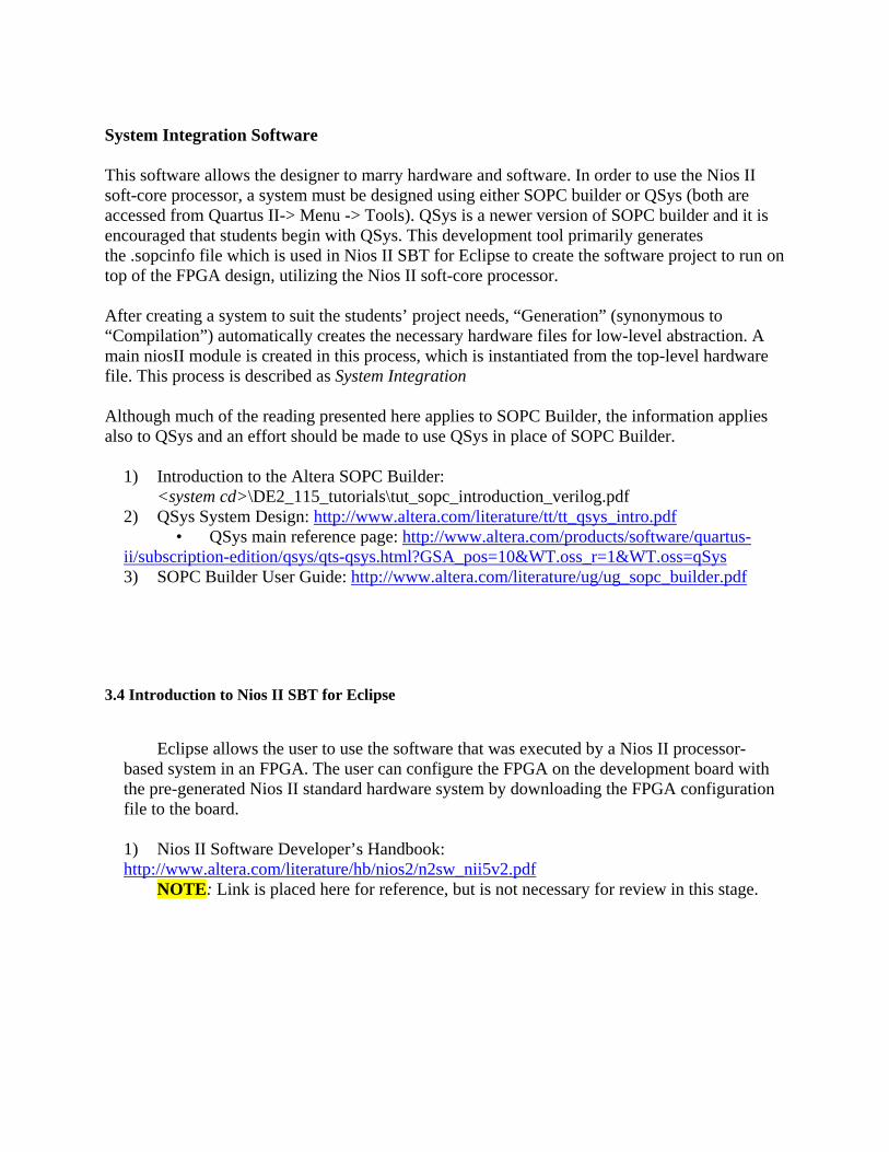
c) Menu -> File -> New -> Nios II Application and BSP from Template
i) Under “Target Hardware Information” select file
<directory>\nios.sopcinfo ii) Under “Application Project” type “Binary Adder” as “Project Name” iii) Under “Project Template” select “helloWorld” iv) Click “Finish”
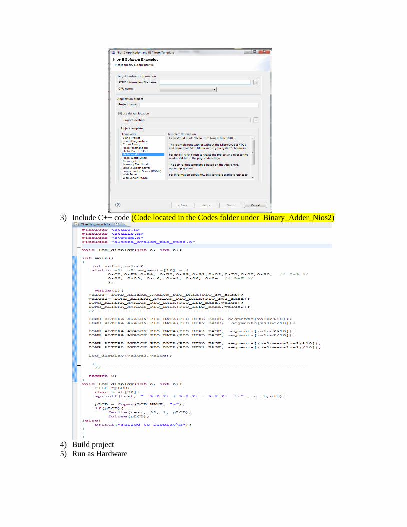
3) Include C++ code (Code located in the Codes folder under Binary_Adder_Nios2)
4) Build project 5) Run as Hardware