Embed Size (px)
Citation preview

Integrated Computer Solutions, Inc.
Internet of Things:
Using MRAA to Abstract Platform
I/O Capabilities
Using MRAA to Abstract Platform I/O Capabilities
- 1 -
Contents
1. Abstract ........................................................................................................................................................... 3
2. MRAA Overview .............................................................................................................................................. 3
2.1. Obtaining MRAA APIs and API Documentation ........................................................................................... 4
2.2. GPIO Pin Names ........................................................................................................................................... 4
2.3. General MRAA Usage ................................................................................................................................... 4
2.4. MRAA Include Files ...................................................................................................................................... 5
3. Using MRAA with Analog Devices ................................................................................................................... 6
3.1. Voltage Reference ........................................................................................................................................ 6
3.2. Analog to Digital Converter (ADC) Resolution ............................................................................................. 6
3.3. Interpreting the Data ................................................................................................................................... 6
3.4. Analog Example ............................................................................................................................................ 7
4. Using MRAA with Digital Devices .................................................................................................................... 8
4.1. Digital Input Example ................................................................................................................................... 8
4.2. Interrupt Handlers ....................................................................................................................................... 9
4.3. Digital Output Example .............................................................................................................................. 11
5. Using MRAA with Pulse Width Modulation (PWM) and Digital Devices ...................................................... 12
5.1. General Rules of Use .................................................................................................................................. 12
5.2. PWM Example ............................................................................................................................................ 12
6. Using MRAA with Inter-Integrated Circuits (I2C) .......................................................................................... 14
6.1. I2C Example ................................................................................................................................................ 14
7. Using MRAA with Universal Asynchronous Receivers/Transmitters (UART) ................................................ 15
7.1. UART Example ............................................................................................................................................ 16
8. Closing ........................................................................................................................................................... 19
Using MRAA to Abstract Platform I/O Capabilities
- 2 -
Revision History
Description Date/Version
Initial Release 4-24-2015
Using MRAA to Abstract Platform I/O Capabilities
- 3 -
1. Abstract
This white paper explains the general usage of the MRAA APIs that can greatly simplify working
with various types of devices, such as:
Analog input
Digital input and output
Pulse width modulation (PWM)
Inter-Integrated 2-wire bus (I2C) devices
Devices that use Universal Asynchronous Receiver-Transmitter (UART) hardware
Instead of complete program examples, this document contains excerpts of C code that
demonstrate the central principles of the MRAA APIs. To get the most out of the information in
this document, you should know or have the following things in hand:
Familiar with the Linux operating system and C programming language.
Basic understanding of digital electronics and the use of GPIOs.
Have specification sheets for the devices that are to be used.
Note: This document does not explain compiling or linking code, or installingsoftware on a given
platform.
2. MRAA Overview
MRAA (pronounced em-rah) is a low-level library written in the C language. The purpose of
MRAA is to abstract the details associated with accessing and manipulating the basic I/O
capabilities of a platforms, such as the Intel® Galileo or Intel® Edison boards, into a single,
concise API. See below for more details:
MRAA serves as a translation layer on top of the Linux General Purpose Input/Outputs
(GPIO) facilities. Although Linux provides a fairly rich infrastructure for manipulating
GPIOs, and its generic instructions for handling GPIOs are fairly standard, it can be
difficult to use.
By definition, all platforms vary. They each have different capabilities, pin numbers, and
types of GPIOs. For instance, a GPIO pin may not support the same type of capabilities
from one platform to the next. A pin may not even exist on a given platform. Further, the
way in which GPIOs are configured on a platform depends on various factors. For
instance, using a GPIO pin in one mode may preclude using another pin in another
mode, or in using another pin at all. Therefore, MRAA makes developing programs less
complicated because it can be used along with other software to create platform-
independent code.
Note: Although MRAA can be used to write platform-independent code, developers are
still responsible for ensuring that code is robust enough to accommodate the various
limitations of the platforms it may run on.
Using MRAA to Abstract Platform I/O Capabilities
- 4 -
2.1. Obtaining MRAA APIs and API Documentation
The MRAA package is already installed on Intel Galileo and Edison hardware and can be linked
into your code as described below. You can also obtain recent versions from the Intel source
code repository.
API documentation is available at: http://iotdk.intel.com/docs/master/mraa/
2.2. GPIO Pin Names
This white paper refers to various “pins.” These hardware pins are typically referred to by a
number. Pin numbers may also be prefixed by a character, such as “D” for digital or “A” for
analog. For example, “D0” would refer to the digital pin 0, while “A3” would refer to the analog
input pin 3. A pin may also be referenced as something like GPIO6, referring to GPIO pin 6,
without the “D” or “A” reference to analog or digital.
2.3. General MRAA Usage
Before beginning to code, certain guidelines should be followed:
1. The MRAA library must be linked into your software. Typically, you must first initialize
MRAA with a statement, such as:
mraa_result_t rv;
rv = mraa_init();
if (rv != MRAA_SUCCESS)
<report the error, insert your own code below>
. . .
2. Many MRAA functions return an mraa_result_t value. It is important for you to confirm
that the specific function succeeded.
3. The examples in this document do not provide error-checking. It is highly recommended
that you error-check everything.
4. After initialization, you should indicate to MRAA that you will use a specific pin for a
given purpose. The code examples used later in this document demonstrate this action.
5. Once done (that is, before exiting the program), you should tell MRAA to release the
pin(s) so that it cleans up any internal states. The code examples used later in this
document demonstrate this action.
Using MRAA to Abstract Platform I/O Capabilities
- 5 -
2.4. MRAA Include Files
The main Include file used for MRAA is mraa.h, along with any device-dependent Include files,
for example:
An analog device would include:
#include <mraa.h>
#include <mraa/aio.h>
A digital device would add:
#include <mraa/gpio.h>
Using MRAA to Abstract Platform I/O Capabilities
- 6 -
3. Using MRAA with Analog Devices
An analog device is one that provides data in the form of a changing voltage level from 0 to the
highest voltage supported. This data is typically referred to as the Analog Reference Voltage
(AREF). For example, an analog pressure sensor may provide data as a voltage starting at 0
(indicating no pressure) and then increasing as the pressure increases. This sensor’s voltages
are then interpreted and converted to a digital number by a device called an Analog to Digital
Converter (ADC). The software controlling the sensor then reads this number generated by the
ADC.
The information below is important to have when interpreting data from an analog sensor.
These items are discussed individually in the following subsections.
1. The voltage reference (AREF) value
2. The resolution of the ADC
3. How to interpret thedata (depends on the type of sensor)
3.1. Voltage Reference
The voltage reference is typically 3.3 volts or 5.0 volts DC. However, the reference voltage may
vary because some platforms, such as the Intel® Edison board, allow you to generate a custom
AREF for the platform instead of using its own built-in AREF. Therefore, you need to know this
AREF before you can obtain meaningful data from such devices.
3.2. Analog to Digital Converter (ADC) Resolution
The ADC resolution is very important, as it can determine the precision of your measurements.
All ADCs in use on the Intel platforms support resolutions of 1024 (10 bits), and at least in the
case of the Intel® Edison board, 4096 (12 bits).
You can determine the approximate voltage “steps” that can be represented by dividing the
AREF value by the ADC resolution. This number is then used by your application. To determine
the voltage steps, divide the AREF of 5.0 volts by the ADC resolution of 1024. The result is that
each step returned from the ADC represents approximately 4 millivolts.
5.0 / 1024.0 = 0.00488 volts
3.3. Interpreting the Data
With the information above, you can determine the approximate voltage level present on the
device’s analog input pin. The higher the ADC resolution, the more precise your voltage
measurement will be.
Using MRAA to Abstract Platform I/O Capabilities
- 7 -
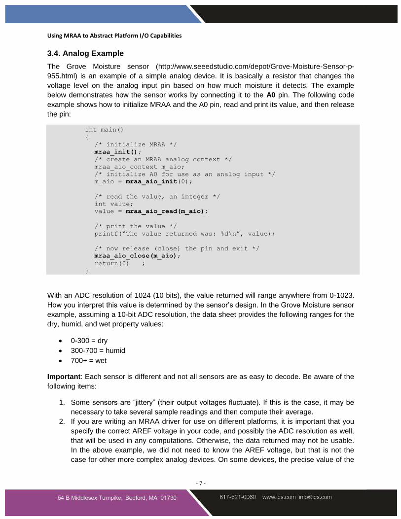
3.4. Analog Example
The Grove Moisture sensor (http://www.seeedstudio.com/depot/Grove-Moisture-Sensor-p-
955.html) is an example of a simple analog device. It is basically a resistor that changes the
voltage level on the analog input pin based on how much moisture it detects. The example
below demonstrates how the sensor works by connecting it to the A0 pin. The following code
example shows how to initialize MRAA and the A0 pin, read and print its value, and then release
the pin:
int main()
{
/* initialize MRAA */
mraa_init();
/* create an MRAA analog context */
mraa_aio_context m_aio;
/* initialize A0 for use as an analog input */
m_aio = mraa_aio_init(0);
/* read the value, an integer */
int value;
value = mraa_aio_read(m_aio);
/* print the value */
printf(“The value returned was: %d\n”, value);
/* now release (close) the pin and exit */
mraa_aio_close(m_aio);
return(0) ;
}
With an ADC resolution of 1024 (10 bits), the value returned will range anywhere from 0-1023.
How you interpret this value is determined by the sensor’s design. In the Grove Moisture sensor
example, assuming a 10-bit ADC resolution, the data sheet provides the following ranges for the
dry, humid, and wet property values:
0-300 = dry
300-700 = humid
700+ = wet
Important: Each sensor is different and not all sensors are as easy to decode. Be aware of the
following items:
1. Some sensors are “jittery” (their output voltages fluctuate). If this is the case, it may be
necessary to take several sample readings and then compute their average.
2. If you are writing an MRAA driver for use on different platforms, it is important that you
specify the correct AREF voltage in your code, and possibly the ADC resolution as well,
that will be used in any computations. Otherwise, the data returned may not be usable.
In the above example, we did not need to know the AREF voltage, but that is not the
case for other more complex analog devices. On some devices, the precise value of the
Using MRAA to Abstract Platform I/O Capabilities
- 8 -
AREF voltage and ADC resolution will be required in order to determine the sensor's
output.
4. Using MRAA with Digital Devices
A digital device is one that deals in LOW and HIGH values, where LOW refers to a low voltage
level and HIGH refers to a high voltage level. Only two states can be represented. For example,
in a 5.0v system, LOW might refer to 0 volts and HIGH might refer to 5.0 volts. Typically,
however, HIGH is represented by a 1, and LOW is represented by a 0.
Digital devices can be set up as an input or an output. For use as an input device, you would
use MRAA to read the digital pin and return a value indicating whether the voltage was LOW or
HIGH. Conversely, writing to a digital device causes the digital pin to be driven LOW or HIGH.
MRAA provides an API for reading and writing the states of a digital pin. In addition, it is
possible to attach a user supplied interrupt handler to a digital input. Interrupt handlers are
discussed on page 9. To use MRAA’s digital input and output facilities you need this header file:
#include <mraa/gpio.h>
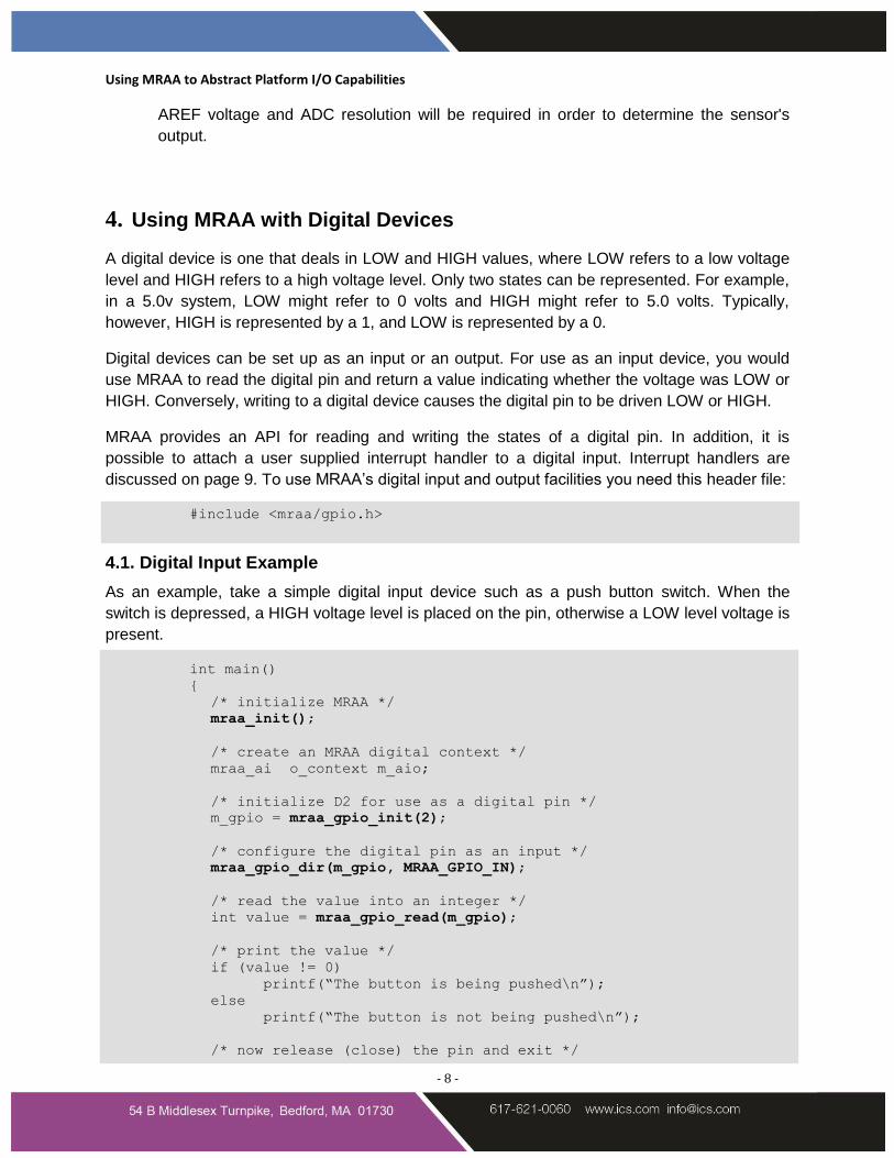
4.1. Digital Input Example
As an example, take a simple digital input device such as a push button switch. When the
switch is depressed, a HIGH voltage level is placed on the pin, otherwise a LOW level voltage is
present.
int main()
{
/* initialize MRAA */
mraa_init();
/* create an MRAA digital context */
mraa_ai o_context m_aio;
/* initialize D2 for use as a digital pin */
m_gpio = mraa_gpio_init(2);
/* configure the digital pin as an input */
mraa_gpio_dir(m_gpio, MRAA_GPIO_IN);
/* read the value into an integer */
int value = mraa_gpio_read(m_gpio);
/* print the value */
if (value != 0)
printf(“The button is being pushed\n”);
else
printf(“The button is not being pushed\n”);
/* now release (close) the pin and exit */
Using MRAA to Abstract Platform I/O Capabilities
- 9 -
mraa_gpio_close(m_gpio);
return(0);
}
As you can see, this is pretty straightforward. Notice also how we told MRAA to configure the
pin as an input using mraa_gpio_dir(). Digital pins can be used for either input or output, unlike
analog pins, which are always input only.
4.2. Interrupt Handlers
In some cases, you will not want to have to keep re-reading a digital pin to determine its status.
Take for example a sensor that is attached to a motor for the purpose of counting revolutions
per minute (RPM). In this case, it would be somewhat painful and error prone to keep re-reading
the pin (the device) to detect changes constantly.
MRAA provides the ability to create an interrupt handler and attach it to a pin. In this case,
MRAA will ensure that your interrupt handler will be called whenever a specified change of the
pin's state/transition occurs (LOW to HIGH or HIGH to LOW).
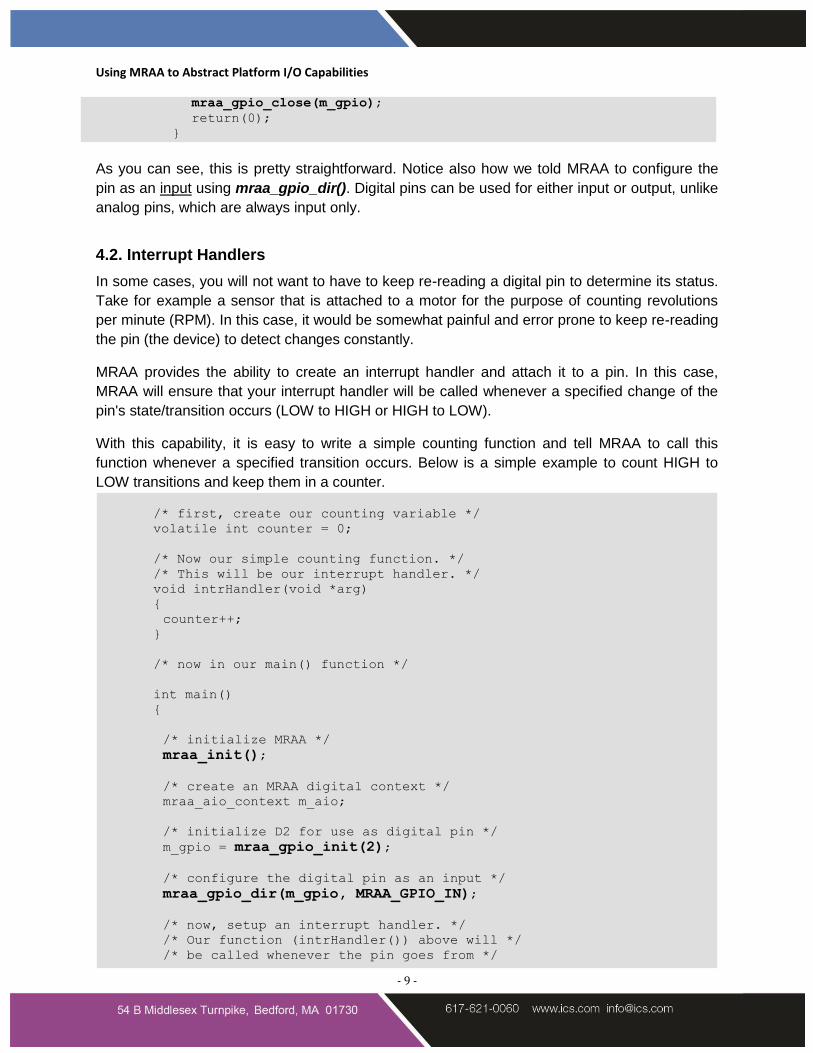
With this capability, it is easy to write a simple counting function and tell MRAA to call this
function whenever a specified transition occurs. Below is a simple example to count HIGH to
LOW transitions and keep them in a counter.
/* first, create our counting variable */
volatile int counter = 0;
/* Now our simple counting function. */
/* This will be our interrupt handler. */
void intrHandler(void *arg)
{
counter++;
}
/* now in our main() function */
int main()
{
/* initialize MRAA */
mraa_init();
/* create an MRAA digital context */
mraa_aio_context m_aio;
/* initialize D2 for use as digital pin */
m_gpio = mraa_gpio_init(2);
/* configure the digital pin as an input */
mraa_gpio_dir(m_gpio, MRAA_GPIO_IN);
/* now, setup an interrupt handler. */
/* Our function (intrHandler()) above will */
/* be called whenever the pin goes from */
Using MRAA to Abstract Platform I/O Capabilities
- 10 -
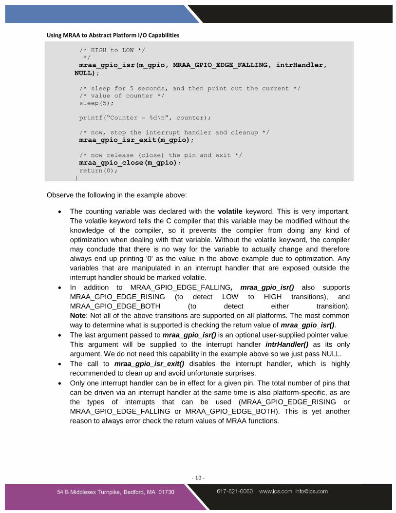
/* HIGH to LOW */
*/
mraa_gpio_isr(m_gpio, MRAA_GPIO_EDGE_FALLING, intrHandler,
NULL);
/* sleep for 5 seconds, and then print out the current */
/* value of counter */
sleep(5);
printf(“Counter = %d\n”, counter);
/* now, stop the interrupt handler and cleanup */
mraa_gpio_isr_exit(m_gpio);
/* now release (close) the pin and exit */
mraa_gpio_close(m_gpio);
return(0);
}
Observe the following in the example above:
The counting variable was declared with the volatile keyword. This is very important.
The volatile keyword tells the C compiler that this variable may be modified without the
knowledge of the compiler, so it prevents the compiler from doing any kind of
optimization when dealing with that variable. Without the volatile keyword, the compiler
may conclude that there is no way for the variable to actually change and therefore
always end up printing '0' as the value in the above example due to optimization. Any
variables that are manipulated in an interrupt handler that are exposed outside the
interrupt handler should be marked volatile.
In addition to MRAA_GPIO_EDGE_FALLING, mraa_gpio_isr() also supports
MRAA_GPIO_EDGE_RISING (to detect LOW to HIGH transitions), and
MRAA_GPIO_EDGE_BOTH (to detect either transition).
Note: Not all of the above transitions are supported on all platforms. The most common
way to determine what is supported is checking the return value of mraa_gpio_isr().
The last argument passed to mraa_gpio_isr() is an optional user-supplied pointer value.
This argument will be supplied to the interrupt handler intrHandler() as its only
argument. We do not need this capability in the example above so we just pass NULL.
The call to mraa_gpio_isr_exit() disables the interrupt handler, which is highly
recommended to clean up and avoid unfortunate surprises.
Only one interrupt handler can be in effect for a given pin. The total number of pins that
can be driven via an interrupt handler at the same time is also platform-specific, as are
the types of interrupts that can be used (MRAA_GPIO_EDGE_RISING or
MRAA_GPIO_EDGE_FALLING or MRAA_GPIO_EDGE_BOTH). This is yet another
reason to always error check the return values of MRAA functions.
Using MRAA to Abstract Platform I/O Capabilities
- 11 -
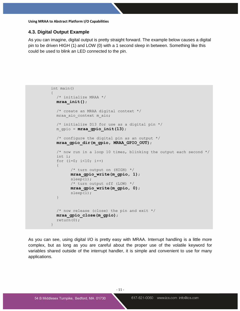
4.3. Digital Output Example
As you can imagine, digital output is pretty straight forward. The example below causes a digital
pin to be driven HIGH (1) and LOW (0) with a 1 second sleep in between. Something like this
could be used to blink an LED connected to the pin.
int main()
{
/* initialize MRAA */
mraa_init();
/* create an MRAA digital context */
mraa_aio_context m_aio;
/* initialize D13 for use as a digital pin */
m_gpio = mraa_gpio_init(13);
/* configure the digital pin as an output */
mraa_gpio_dir(m_gpio, MRAA_GPIO_OUT);
/* now run in a loop 10 times, blinking the output each second */
int i;
for (i=0; i<10; i++)
{
/* turn output on (HIGH) */
mraa_gpio_write(m_gpio, 1);
sleep(1);
/* turn output off (LOW) */
mraa_gpio_write(m_gpio, 0);
sleep(1);
}
/* now release (close) the pin and exit */
mraa_gpio_close(m_gpio);
return(0);
}
As you can see, using digital I/O is pretty easy with MRAA. Interrupt handling is a little more
complex, but as long as you are careful about the proper use of the volatile keyword for
variables shared outside of the interrupt handler, it is simple and convenient to use for many
applications.
Using MRAA to Abstract Platform I/O Capabilities
- 12 -
5. Using MRAA with Pulse Width Modulation (PWM) and Digital Devices
Pulse Width Modulation (PWM) is a type of digital output. The output of a PWM pin is composed
of two elements, the period and the duty cycle:
The period represents how often a pulse should be generated.
The duty-cycle represents how much of that period should be in the HIGH state.
For example, if you have set a period of 2 milliseconds, and a duty cycle of 50%, then you will
get a repeating pattern of 1ms HIGH and 1ms LOW, and then the period repeats. This capability
can be used for a variety of functions, such as dimming an LED or controlling the speed of a
motor by increasing or decreasing the duty cycle.
5.1. General Rules of Use
MRAA provides the ability to configure a digital output to act as a PWM output. It is
important to check your platform to find out which GPIOs can be used as a PWM output.
This will vary from platform to platform.
Platforms vary in the lengths of the periods allowed; therefore, it's important to error
check your MRAA calls.
Some devices have requirements for the lengths of the periods that can be used with
them. For example, a servo motor will typically require a period of 20ms.
The header needed for using MRAA's PWM facilities is:
#include <mraa/pwm.h>
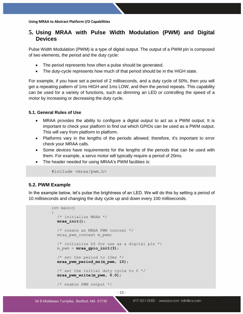
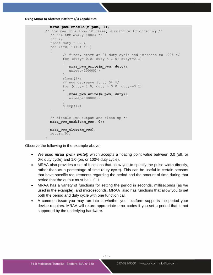
5.2. PWM Example
In the example below, let’s pulse the brightness of an LED. We will do this by setting a period of
10 milliseconds and changing the duty cycle up and down every 100 milliseconds.
int main()
{
/* initialize MRAA */
mraa_init();
/* create an MRAA PWM context */
mraa_pwm_context m_pwm;
/* initialize D3 for use as a digital pin */
m_pwm = mraa_gpio_init(3);
/* set the period to 10ms */
mraa_pwm_period_ms(m_pwm, 10);
/* set the initial duty cycle to 0 */
mraa_pwm_write(m_pwm, 0.0);
/* enable PWM output */
Using MRAA to Abstract Platform I/O Capabilities
- 13 -
mraa_pwm_enable(m_pwm, 1);
/* now run in a loop 10 times, dimming or brightening /*
/* the LED every 100ms */
int i;
float duty = 0.0;
for (i=0; i<10; i++)
{
/* first, start at 0% duty cycle and increase to 100% */
for (duty= 0.0; duty < 1.0; duty+=0.1)
{
mraa_pwm_write(m_pwm, duty);
usleep(100000);
}
sleep(1);
/* now decrease it to 0% */
for (duty= 1.0; duty > 0.0; duty-=0.1)
{
mraa_pwm_write(m_pwm, duty);
usleep(100000);
}
sleep(1);
}
/* disable PWM output and clean up */
mraa_pwm_enable(m_pwm, 0);
mraa_pwm_close(m_pwm);
return(0);
}
Observe the following in the example above:
We used mraa_pwm_write() which accepts a floating point value between 0.0 (off, or
0% duty cycle) and 1.0 (on, or 100% duty cycle).
MRAA also provides a set of functions that allow you to specify the pulse width directly,
rather than as a percentage of time (duty cycle). This can be useful in certain sensors
that have specific requirements regarding the period and the amount of time during that
period that the output must be HIGH.
MRAA has a variety of functions for setting the period in seconds, milliseconds (as we
used in the example), and microseconds. MRAA also has functions that allow you to set
both the period and duty cycle with one function call.
A common issue you may run into is whether your platform supports the period your
device requires. MRAA will return appropriate error codes if you set a period that is not
supported by the underlying hardware.
Using MRAA to Abstract Platform I/O Capabilities
- 14 -
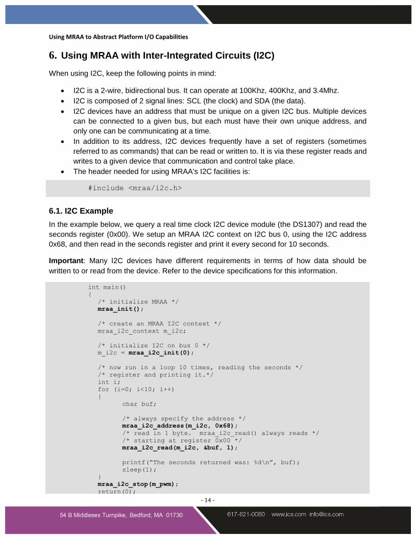
6. Using MRAA with Inter-Integrated Circuits (I2C)
When using I2C, keep the following points in mind:
I2C is a 2-wire, bidirectional bus. It can operate at 100Khz, 400Khz, and 3.4Mhz.
I2C is composed of 2 signal lines: SCL (the clock) and SDA (the data).
I2C devices have an address that must be unique on a given I2C bus. Multiple devices
can be connected to a given bus, but each must have their own unique address, and
only one can be communicating at a time.
In addition to its address, I2C devices frequently have a set of registers (sometimes
referred to as commands) that can be read or written to. It is via these register reads and
writes to a given device that communication and control take place.
The header needed for using MRAA's I2C facilities is:
#include <mraa/i2c.h>
6.1. I2C Example
In the example below, we query a real time clock I2C device module (the DS1307) and read the
seconds register (0x00). We setup an MRAA I2C context on I2C bus 0, using the I2C address
0x68, and then read in the seconds register and print it every second for 10 seconds.
Important: Many I2C devices have different requirements in terms of how data should be
written to or read from the device. Refer to the device specifications for this information.
int main()
{
/* initialize MRAA */
mraa_init();
/* create an MRAA I2C context */
mraa_i2c_context m_i2c;
/* initialize I2C on bus 0 */
m_i2c = mraa_i2c_init(0);
/* now run in a loop 10 times, reading the seconds */
/* register and printing it.*/
int i;
for (i=0; i<10; i++)
{
char buf;
/* always specify the address */
mraa_i2c_address(m_i2c, 0x68);
/* read in 1 byte. mraa_i2c_read() always reads */
/* starting at register 0x00 */
mraa_i2c_read(m_i2c, &buf, 1);
printf(“The seconds returned was: %d\n”, buf);
sleep(1);
}
mraa_i2c_stop(m_pwm);
return(0);
Using MRAA to Abstract Platform I/O Capabilities
- 15 -
}
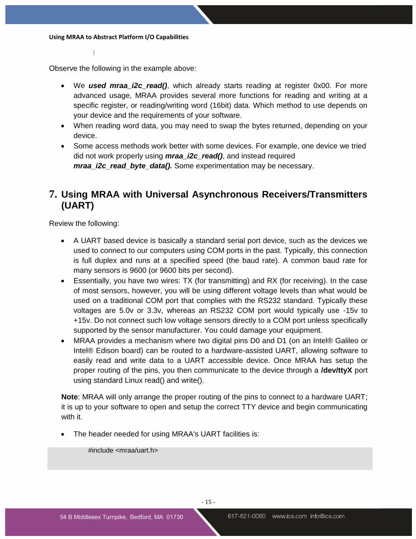
Observe the following in the example above:
We used mraa_i2c_read(), which already starts reading at register 0x00. For more
advanced usage, MRAA provides several more functions for reading and writing at a
specific register, or reading/writing word (16bit) data. Which method to use depends on
your device and the requirements of your software.
When reading word data, you may need to swap the bytes returned, depending on your
device.
Some access methods work better with some devices. For example, one device we tried
did not work properly using mraa_i2c_read(), and instead required
mraa_i2c_read_byte_data(). Some experimentation may be necessary.
7. Using MRAA with Universal Asynchronous Receivers/Transmitters (UART)
Review the following:
A UART based device is basically a standard serial port device, such as the devices we
used to connect to our computers using COM ports in the past. Typically, this connection
is full duplex and runs at a specified speed (the baud rate). A common baud rate for
many sensors is 9600 (or 9600 bits per second).
Essentially, you have two wires: TX (for transmitting) and RX (for receiving). In the case
of most sensors, however, you will be using different voltage levels than what would be
used on a traditional COM port that complies with the RS232 standard. Typically these
voltages are 5.0v or 3.3v, whereas an RS232 COM port would typically use -15v to
+15v. Do not connect such low voltage sensors directly to a COM port unless specifically
supported by the sensor manufacturer. You could damage your equipment.
MRAA provides a mechanism where two digital pins D0 and D1 (on an Intel® Galileo or
Intel® Edison board) can be routed to a hardware-assisted UART, allowing software to
easily read and write data to a UART accessible device. Once MRAA has setup the
proper routing of the pins, you then communicate to the device through a /dev/ttyX port
using standard Linux read() and write().
Note: MRAA will only arrange the proper routing of the pins to connect to a hardware UART;
it is up to your software to open and setup the correct TTY device and begin communicating
with it.
The header needed for using MRAA's UART facilities is:
#include <mraa/uart.h>
Using MRAA to Abstract Platform I/O Capabilities
- 16 -
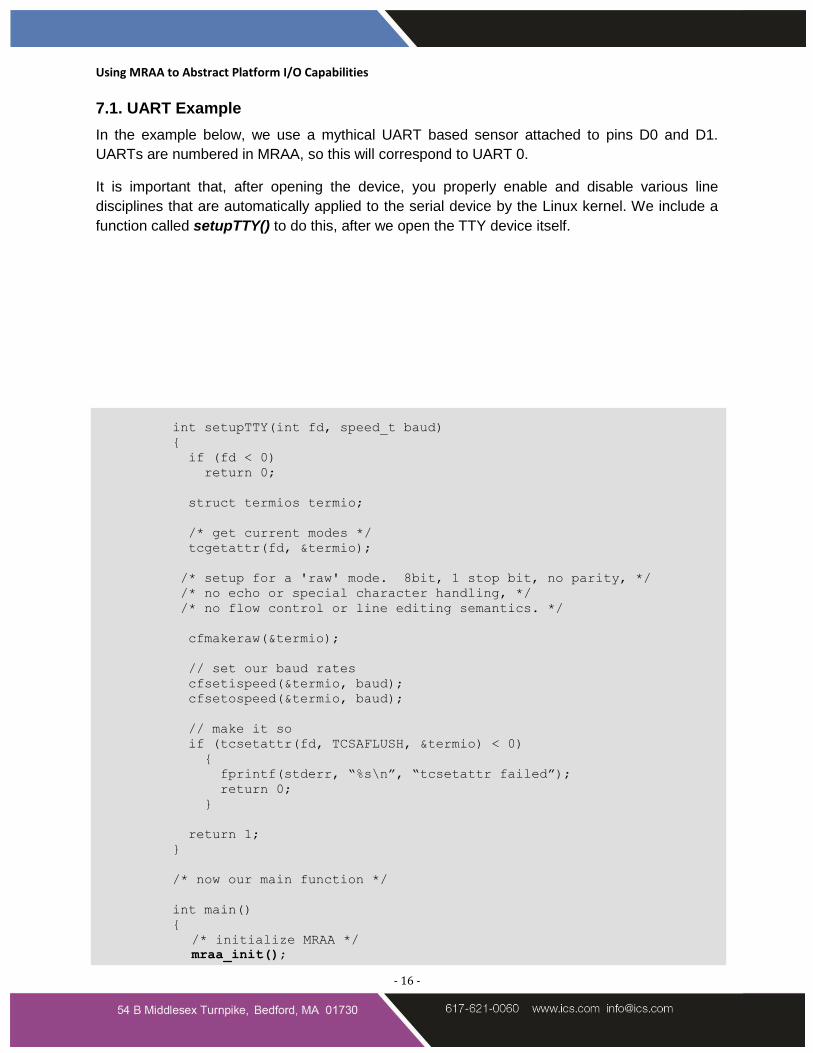
7.1. UART Example
In the example below, we use a mythical UART based sensor attached to pins D0 and D1.
UARTs are numbered in MRAA, so this will correspond to UART 0.
It is important that, after opening the device, you properly enable and disable various line
disciplines that are automatically applied to the serial device by the Linux kernel. We include a
function called setupTTY() to do this, after we open the TTY device itself.
int setupTTY(int fd, speed_t baud)
{
if (fd < 0)
return 0;
struct termios termio;
/* get current modes */
tcgetattr(fd, &termio);
/* setup for a 'raw' mode. 8bit, 1 stop bit, no parity, */
/* no echo or special character handling, */
/* no flow control or line editing semantics. */
cfmakeraw(&termio);
// set our baud rates
cfsetispeed(&termio, baud);
cfsetospeed(&termio, baud);
// make it so
if (tcsetattr(fd, TCSAFLUSH, &termio) < 0)
{
fprintf(stderr, “%s\n”, “tcsetattr failed”);
return 0;
}
return 1;
}
/* now our main function */
int main()
{
/* initialize MRAA */
mraa_init();
Using MRAA to Abstract Platform I/O Capabilities
- 17 -
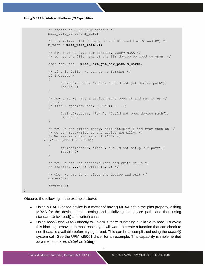
/* create an MRAA UART context */
mraa_uart_context m_uart;
/* initialize UART 0 (pins D0 and D1 used for TX and RX) */
m_uart = mraa_uart_init(0);
/* now that we have our context, query MRAA */
/* to get the file name of the TTY device we need to open. */
char *devPath = mraa_uart_get_dev_path(m_uart);
/* if this fails, we can go no further */
if (!devPath)
{
fprintf(stderr, “%s\n”, “Could not get device path”);
return 0;
}
/* now that we have a device path, open it and set it up */
int fd;
if ((fd = open(devPath, O_RDWR)) == -1)
{
fprintf(stderr, “%s\n”, “Could not open device path”);
return 0;
}
/* now we are almost ready, call setupTTY() and from then on */
/* we can read/write to the device normally. */
/* We assume a baud rate of 9600/ */
if (!setupTTY(fd, B9600))
{
fprintf(stderr, “%s\n”, “Could not setup TTY port”);
return 0;
}
/* now we can use standard read and write calls */
/* read(fd, ...) or write(fd, …) */
/* when we are done, close the device and exit */
close(fd);
return(0);
}
Observe the following in the example above:
Using a UART-based device is a matter of having MRAA setup the pins properly, asking
MRAA for the device path, opening and initializing the device path, and then using
standard Unix* read() and write() calls.
Using read() and write() directly will block if there is nothing available to read. To avoid
this blocking behavior, in most cases, you will want to create a function that can check to
see if data is available before trying a read. This can be accomplished using the select()
system call. See the UPM wt5001 driver for an example. This capability is implemented
as a method called dataAvailable().
Using MRAA to Abstract Platform I/O Capabilities
- 18 -
In the example, we assumed a baud rate of 9600, which is the most common. The
'B9600' constant is defined in the Linux system header files, and of course, other baud
rates are available. You need to select the correct baud rate depending on the device
you are using.
The setupTTY() function used in the example assumes the most common case. It is
unlikely that you will run into a device that has other requirements in this regard, but it's
something to keep in mind.
Using MRAA to Abstract Platform I/O Capabilities
- 19 -
8. Closing
MRAA simplifies that process of accessing and manipulating the basic I/O capabilities of a
platform like Intel® Galileo or Intel® Edison boards. A powerful library, MRAA provides a
consistent approach to using analog, digital, PWM, I2C, and UART devices with these and
similar platforms. It is a key addition to anyone’s Internet of Things tool chest.
About ICS
Integrated Computer Solutions (ICS) fuses extensive domain knowledge and engineering
expertise with a deep understanding of drivers, operating systems, and IoT sensors to develop
custom, embedded systems that feature innovative, easy-to-use user interfaces that consumers
have come to expect. ICS reduces complexity, costs, redundancies and development time while
solving tough engineering challenges up front.
Copyright © 2015 Integrated Computer Solutions, Inc. All rights reserved. This document may not be reproduced without written
consent from Integrated Computer Solutions, Inc. Intel is a registered trademark of Intel Corporation in the U.S. and/or other
countries.