Embed Size (px)
Citation preview

Using IDENT M System T with Ethernet/IP
Introduction The Pepperl+Fuchs IDENT M System T consists of two models MTT3000-F180-B12-V45-MON, which is a read only unit and the MTT6000-F120-B12-V45 which is a read/write unit. Tags that can be used are MTO-xx which have an 8 byte read only number on them and the MTM-C2 which have an 8 byte read only number and 71 bytes of read/write data.
Ethernet/IP The IDENT M System T has RS232, RS485 and Ethernet TCP/IP ports. It does not however directly support Ethernet/IP. In order to talk Ethernet/IP use the converter RTS-UP-1 unit to either convert the TCP/IP or serial data to Ethernet/IP. RTS-UP-1 – Converts one serial and one Ethernet device to Ethernet/IP RTS-UP-4 – Converts four serial and four Ethernet devices to Ethernet/IP This document will show you step by step how to read and write to the MTT devices using Ethernet/IP
Configure the MTT… devices
Set IP Address The first thing to do is to configure the Ethernet settings of your RFID system. Here are the default parameters. Default Ethernet Settings: IP Address: 192.168.0.2 Subnet Mask: 255.255.255.0 Put this IP address into your web browser and logon to the MTT… device. Make sure the IP address of your PC is close. For example set it to 192.168.0.1.

qwerty
Go to the Settings > System > Network tab and set the network parameters correctly as required by your network administrator.
Network configuration screen for the MTT…
After you change the IP address reboot the hardware so the settings will take affect. Reset the IP address of your PC to reconnect to it.
Tim Cicerchi Page 2 8/26/2011

Configure reader Download the Configuration and diagnostic software from the web site. This software will connect to the serial or Ethernet ports so that a configuration can be made. Put your new Ethernet parameters into the Settings > Port settings menu option.
Setting the Network parameters to connect to an MTT… device
Close the port settings dialog box and press connect. It should say connected at the top. Press the Boot String button at bottom to verify that you have a Pepperl+Fuchs ID system connected.
Tim Cicerchi Page 3 8/26/2011

Reading the version information of an MTT… reader Go to the Reader Setup > Configure Reader menu option. Configure the reader like I have suggested. Many other options are possible. Press “Send Setup to Reader” and look for a 0 on the previous screen. Close the window and reconnect to the reader and verify the configuration.
Configuring an MTT… reader
Tim Cicerchi Page 4 8/26/2011

Configure RTS-UP-… Ethernet/IP adapter
Load Ethernet/IP firmware The RTS-UP unit comes with socket server firmware. If you want other firmware for industrial busses like Ethernet/IP, PROFINET, or Modbus/TCP then download this firmware from out web site and send the firmware to the unit using PortVision. Download and install Portvision You may have to reboot your PC to see the RTS unit. Click “Scan”.
Scanning for RTS-UP… devices
Download the Ethernet/IP firmware
Tim Cicerchi Page 5 8/26/2011

If the Scan Results do not show a device with Ethernet/IP firmware; then highlight the device and go to the menu “Device > Upload Firmware” and update the RTS unit with the right firmware. When you install the Ethernet/IP firmware above the .bin file will be in the folder Comtrol > Ethernet/IP > Ethernetip-x.xx.bin
Loading the Ethernet/IP firmware into the RTS-UP…
Using PortVision you can also double click on the scanned unit and configure the IP Address, subnet mask, and gateway.
Tim Cicerchi Page 6 8/26/2011

IP address configuration screen for RTS-UP…
Tim Cicerchi Page 7 8/26/2011

Configure the RTS and MTT to work together Put the IP address of the RTS-UP… unit in a web browser. You will configure the rts-up…unit here.
Go to Ethernet Device Configuration and open up socket 1. Make the configuration changes you see below. Some settings you will have to customize yourself. Things you will need to know to make these settings: PLC IP address PLC controller slot number(Usually 0) Control tag variable, SINT array, where the read data will be placed.
Tim Cicerchi Page 8 8/26/2011

Connect always
MTT port 10000
MTT IP address
Disconnect never
Timeout 100ms
Choose one byte suffix, carriage return is 13 = 0D in MTT software
This option writes to PLC memory automatically
PLC IP address
Variable the data will be written to (SINT array)
Connect
Port configuration screen for RTS-UP… Once all settings have been made, choose “Submit” at bottom of page. Wait for unit to reboot.
Tim Cicerchi Page 9 8/26/2011
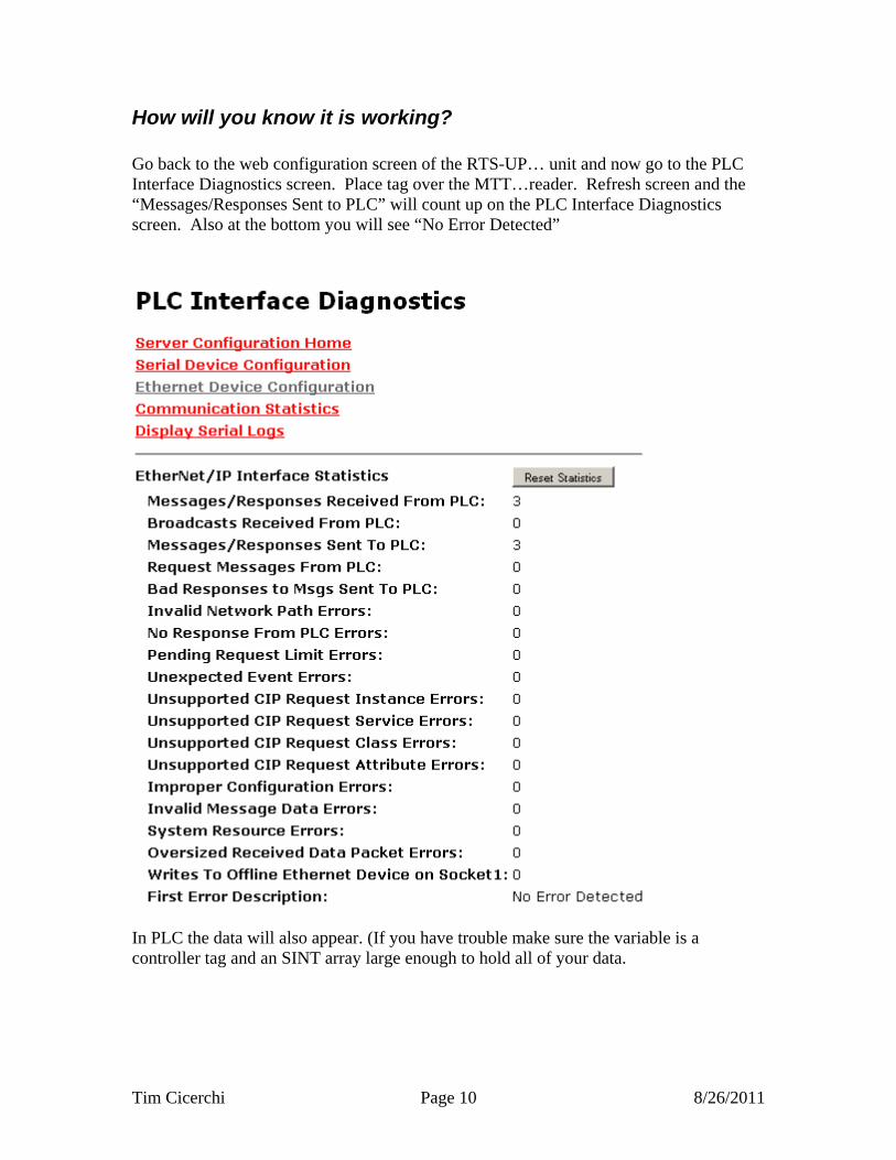
How will you know it is working? Go back to the web configuration screen of the RTS-UP… unit and now go to the PLC Interface Diagnostics screen. Place tag over the MTT…reader. Refresh screen and the “Messages/Responses Sent to PLC” will count up on the PLC Interface Diagnostics screen. Also at the bottom you will see “No Error Detected”
In PLC the data will also appear. (If you have trouble make sure the variable is a controller tag and an SINT array large enough to hold all of your data.
Tim Cicerchi Page 10 8/26/2011

Two byte Counter increments on every new packet
Two byte Length shows how many MTT bytes to follow
…
Data
Suffix
The amount of data will depend on the format of the tag and the “Fixed String Length” parameter that was used when you configured the MTT… unit. In this example I used the “Data+Mark” option. This will display all the read/write data on the tag first, then a colon(:) then the 8 byte fixed code or MARK. If an MTO read only tag was used only the :Mark would be shown because there is no read/write data available.
Tim Cicerchi Page 11 8/26/2011
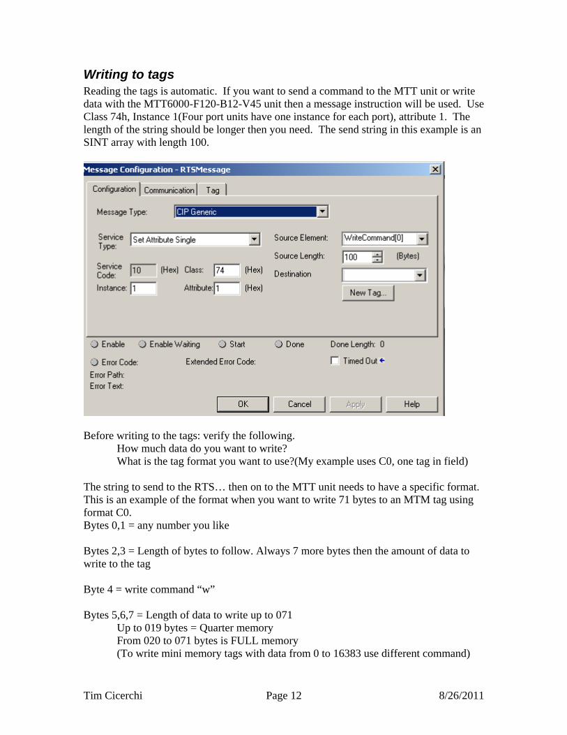
Writing to tags Reading the tags is automatic. If you want to send a command to the MTT unit or write data with the MTT6000-F120-B12-V45 unit then a message instruction will be used. Use Class 74h, Instance 1(Four port units have one instance for each port), attribute 1. The length of the string should be longer then you need. The send string in this example is an SINT array with length 100.
Before writing to the tags: verify the following. How much data do you want to write? What is the tag format you want to use?(My example uses C0, one tag in field) The string to send to the RTS… then on to the MTT unit needs to have a specific format. This is an example of the format when you want to write 71 bytes to an MTM tag using format C0. Bytes 0,1 = any number you like Bytes 2,3 = Length of bytes to follow. Always 7 more bytes then the amount of data to write to the tag Byte 4 = write command “w” Bytes 5,6,7 = Length of data to write up to 071 Up to 019 bytes = Quarter memory From 020 to 071 bytes is FULL memory (To write mini memory tags with data from 0 to 16383 use different command)
Tim Cicerchi Page 12 8/26/2011

Byte 8-78 = data Byte 79-80 = Format C0 = fastest but cannot read multiple tags in field R4 = Longer battery life and a couple tags n field Other options also available Byte 81 = Carriage return or decimal 13
Sequence number
Length to follow, two bytes
Write command
Length, 3 bytes
Data
Tim Cicerchi Page 13 8/26/2011

Carriage return
Tag Format
Tim Cicerchi Page 14 8/26/2011

If you want to format the tag to mini memory because you only need data from 0 up to 16383 and you want the data returned as fast as possible use the command w5xxxxx<CR> where the length is 5 and the data would be 00000 up to 16383 It may take up to 15s to write to a tag. If after 15seconds you don’t see your data returned in the PLC you can retry.
Tim Cicerchi Page 15 8/26/2011