Embed Size (px)
Citation preview

Application Note AC436
May 2020 1© 2020 Microsemi, a Microchip company
Using Device Certificate System Service in SmartFusion2 - Libero SoC v11.7
Table of Contents
PurposeThis application note describes how to read and export device certificate using system services andanalyze the content of the device certificate in SmartFusion®2 system-on-chip (SoC) field programmablegate array (FPGA) devices.
IntroductionThe device certificate includes a digital signature, an electronic analogue of a written signature. Thedigital signature assures that the claimed signatory signed the information. In addition, a digital signaturedetects whether or not the information was modified after it was signed.Microsemi SmartFusion2 device certificate is an X.509 complaint digital certificate that is digitally signedwith a Microsemi private key. The X.509 is an ITU-T standard for a public key infrastructure (PKI) andprivilege management infrastructure (PMI). It specifies standard formats for public key certificates,certificate revocation lists, attribute certificates, and a certification path validation algorithm.The device certificate in the SmartFusion2 devices cryptographically binds the device serial number, datecode, its model or part number, the device’s secret factory key, and a digital signature from Microsemithat is validated internally by the device and externally by the user.The digital certificate is stored in the device’s embedded non-volatile memory (eNVM). The biggerdevices (M2S150 and M2S090) support elliptic curve cryptography (ECC). Therefore, the factory ECCpublic keys are also certified and included in the device certificates.
Purpose . . . . . . . . . . . . . . . . . . . . . . . . . . . . . . . . . . . . . . . . . . . . . . . . . . 1Introduction . . . . . . . . . . . . . . . . . . . . . . . . . . . . . . . . . . . . . . . . . . . . . . . . 1
Device Certificate Application . . . . . . . . . . . . . . . . . . . . . . . . . . . . . . . . . . . . . . . .2SmartFusion2 Device Certificate . . . . . . . . . . . . . . . . . . . . . . . . . . . . . . . . . . . . . 2References . . . . . . . . . . . . . . . . . . . . . . . . . . . . . . . . . . . . . . . . . . . . . . . . 3SmartFusion2 Device Certificate Service . . . . . . . . . . . . . . . . . . . . . . . . . . . . . . . . . 3Using Device Certificate Service . . . . . . . . . . . . . . . . . . . . . . . . . . . . . . . . . . . . . 5Design Requirements . . . . . . . . . . . . . . . . . . . . . . . . . . . . . . . . . . . . . . . . . . . 7Design Description . . . . . . . . . . . . . . . . . . . . . . . . . . . . . . . . . . . . . . . . . . . . 7Hardware Implementation . . . . . . . . . . . . . . . . . . . . . . . . . . . . . . . . . . . . . . . . . 8Software Implementation . . . . . . . . . . . . . . . . . . . . . . . . . . . . . . . . . . . . . . . . . 9Setting Up the Design . . . . . . . . . . . . . . . . . . . . . . . . . . . . . . . . . . . . . . . . . . . 9Running the Design . . . . . . . . . . . . . . . . . . . . . . . . . . . . . . . . . . . . . . . . . . . 11
Viewing Fields in Device Certificate . . . . . . . . . . . . . . . . . . . . . . . . . . . . . . . . . . . . 12Conclusion . . . . . . . . . . . . . . . . . . . . . . . . . . . . . . . . . . . . . . . . . . . . . . . 16Appendix A: Design and Programming Files . . . . . . . . . . . . . . . . . . . . . . . . . . . . . . 17Appendix B: Decoding Device Certificate Using ASN.1 JavaScript Decoder Open Source Tool . . . . 18List of Changes . . . . . . . . . . . . . . . . . . . . . . . . . . . . . . . . . . . . . . . . . . . . . 21

Using Device Certificate System Service in SmartFusion2 - Libero SoC v11.7
2 Rev ision 4
Device Certificate ApplicationThe primary advantage of the device certificate application is to prevent counterfeiting and fraud.Counterfeiting in electronic parts can take various forms, such as:
• Cloning designs at the transistor level• Black-topping and re-marking devices to misrepresent used devices as new• Changing the date codes• Improving the speed grade or the temperature grade, and increasing the alleged screening level
As a result, any mismatch between how the device is represented by its shipping paperwork or the labelprinted on its surface and the digital certificate indicates the possibility of counterfeiting fraud.One application for a SmartFusion2 device certificate is that if a counterfeiter remarks a device with afaster speed grade, the model number authenticated in the device certificate still reflects the true speedgrade. When the user attempts to program such a device with a design that was compiled for the fasterspeed grade device, the programmer observes that the speed grade reflected in the certificate isincorrect for the design.
SmartFusion2 Device CertificateThe SmartFusion2 device certificate is encoded in the abstract syntax notation one format: ASN.1. It is astandard and notation that describes rules and structures for representing, encoding, transmitting, anddecoding data in telecommunications and computer networking. The formal rules enable representationof objects that are independent of machine-specific encoding techniques. Formal notation makes itpossible to automate the task of validating whether a specific instance of data representation abides bythe specifications.
Table 1 • SmartFusion2 Device Certificate Fields and Descriptions
Field Name Description
Version Contains the version information
Serial Number Contains the serial number information
Signature Algorithm Provides information about the algorithm that is used to generate the signature
Issuer Provides information about certificate issuers information like: Country Name,Organization Unit Name, Organization Name, and Common Name information
Validity Provides information about validity of the certificate• Not Before (start time specified for the certificate validity)• Not After (end time specified for the certificate validity)Note: The certificate is only valid between these specified time fields.
Subject Provides information about generation qualifier, surname, and given name
Subject Public Key Info Provides the information about the public key generation algorithm and publickey information• Public Key Algorithm• Subject Public Key
Issuer Unique Identifier It contains issuer unique identification string of 9 bytes size
Subject Unique Identifier It contains 0 x 00 + factory serial number (FSN) + serial number modifier(SNM). For more information about FSN and SNM descriptions, refer to theUG0443: SmartFusion2 and IGLOO2 FPGA Security and Reliability UserGuide.
Extensions Reserved

References
Revision 4 3
ReferencesThe following list of references is used in this document:
• UG0331: SmartFusion2 Microcontroller Subsystem User Guide • UG0450: SmartFusion2 SoC and IGLOO2 FPGA System Controller User Guide • UG0443: SmartFusion2 and IGLOO2 FPGA Security and Reliability User Guide
SmartFusion2 Device Certificate ServiceSmartFusion2 device certificate service is a part of device and design information services of the systemservices. These system services are performed by the system controller block.The device certificate service provides access to the system controller’s device and design informationservices. This service is accessed through the communication block (COMM_BLK).There are two COMM_BLK instances:
• Located in the microcontroller sub system (MSS)• Located in the system controller
The COMM_BLK consists of an APB interface, eight byte transmit FIFO, and eight byte receive FIFO.The COMM_BLK provides a bi-directional message passing facility between the MSS and the systemcontroller. The device certificate service is initiated using the COMM_BLK in the MSS, which can be read or writtenby any master on the AMBA high performance bus (AHB) matrix; typically either the ARM® Cortex®-M3processor or a design in the FPGA fabric (also known as a fabric master).The system controller receives the command through the COMM_BLK in the system controller. Oncompletion of the requested service, the system controller returns a status message through theCOMM_BLK. The responses generated are based on the selected command.
Certificate Signature Algorithm Provides information about the algorithm that is being used.
Certificate Signature Provides the certificate signature information. The signature of theSmartFusion2 device certificate can be verified using Microsemi public key.
Table 1 • SmartFusion2 Device Certificate Fields and Descriptions (continued)
Field Name Description

Using Device Certificate System Service in SmartFusion2 - Libero SoC v11.7
4 Rev ision 4
Figure 1 shows the system controller block in SmartFusion2.
Figure 1 • System Controller Interface with MSS and FPGA Fabric

Using Device Certificate Service
Revision 4 5
Using Device Certificate ServiceThe device certificate service is initiated using the COMM_BLK. The COMM_BLK base address residesat 0x40016000 and extends to address 0x40016FFF in the Cortex-M3 processor memory map. Table 2summarizes the control and status registers for the COMM_BLK.For more information about COMM_BLK registers description, refer to the "Communication Block"chapter in the UG0331: SmartFusion2 Microcontroller Subsystem User Guide.
The following are the basic steps to use the device certificate system service in the SmartFusion2devices:
1. Disable the COMM BLOCK loop back mode by writing "1" to LOOPBACK bit (bit-5) of theCONTROL register (0x40016000).
2. Enable the COMM block by writing "1" to ENABLE bit (bit-4) of the CONTROL register.3. Enable the receive interrupt by writing "1" to RCVOKAY bit (bit-1) of the INT_ENABLE register
(0x40016008).4. Enable the COMM_BLK_INTR (INTISR[19]) in Cortex-M3 Processor interrupts.5. Set up the COMM_BLK register in byte mode by writing "0" to SIZETX bit (bit-2) of the CONTROL
register.6. Wait for the TXTOKAY bit (bit-0) of STATUS register(0X40016004) to become 1.7. Send the device certificate command by writing the register FRAME_START8 with the command
value. The command value of the device certificate service is 0x00.8. Set up the COMM_BLK in 4 bytes mode by writing "1" to SIZETX bit (bit-2) of the CONTROL
register.9. Wait for the TXTOKAY status bit to become 1.10. Send the DEVICECERTPTR address, by writing the register DATA32 with the DEVICECERTPTR
value. For more information about the device certificate service request details, refer to Table 3 onpage 6.
11. After completion of the device certificate service, system controller returns a response throughthe COMM_BLK instance.
12. The service response includes the 1 byte command, 1 byte STATUS, and 4 bytesDEVICECERTPTR value. The 768 Bytes device certificate is stored in the location pointed by theDEVICECERTPTR pointer. For more information about device certificate service responsedetails, refer to Table 4 on page 6.
Note: Microsemi recommends using system services driver provided in the firmware core configurator fordetailed implementation of the device certificate service.
Table 2 • COMM_BLK Register Map
Register Name Address Offset R/W Reset Value Description
CONTROL 0 x 00 R/W 0 x 00 Control Register
STATUS 0 x 04 R/W 0 x 00 Status Register
INT_ENABLE 0 x 08 R/W 0 x 00 Interrupt Enable
DATA8 0 x 10 R/W 0 x 00 Byte Data Register
DATA32 0 x 14 R/W 0 x 00000000 Word Data Register
FRAME_START8 0 x 18 R/W 0 x 00 Frame/Command Byte Register
FRAME_START32 0 x 1c R/W 0 x 00000000 Frame/Command Word Register

Using Device Certificate System Service in SmartFusion2 - Libero SoC v11.7
6 Rev ision 4
Table 3 shows the device certificate service request details.
Table 4 shows the device certificate service response details.
For more information about System Controller, refer to the UG0450: SmartFusion2 SoC and IGLOO2FPGA System Controller User Guide.For more information about COMM_BLK, refer to the Communication Block chapter in theUG0331: SmartFusion2 Microcontroller Subsystem User Guide.
Table 3 • Device Certificate Service Request
Offset Length (bytes) Field Description
0 1 CMD = 0 Command
1 4 DEVICECERTPTR Pointer to 768-byte buffer to receive the device certificate.
Table 4 • Device Certificate Service Response
Offset Length (bytes) Field Description
0 1 CMD = 0 Command
1 1 STATUS Command status
2 4 DEVICECERTPTR Pointer to original buffer from request

Design Requirements
Revision 4 7
Design RequirementsTable 5 shows the design requirements.
Design DescriptionThe design is implemented on the SmartFusion2 Security Evaluation Kit board using the M2S090TS-1FGG484 device.The design example consists of:
• RC oscillator• Fabric CCC• CORERESET• MSS (DeviceCertificate_MSS_0)
The fabric PLL is used to provide the base clock for the MSS. The system services are run using variousC routines in the MSS, as shown in the following sections. In addition, a universal asynchronousreceiver/transmitter (UART1) in the MSS is used to display the device certificate information.
Table 5 • Design Requirements
Design Requirements Description
Hardware Requirements
SmartFusion2 Security Evaluation Kit:• 12 V adapter• FlashPro4 programmer• USB A to Mini-B cable
Rev D or later
Host PC or Laptop Any 64-bit Windows Operating System
Software Requirements
Libero® SoC v11.7
SoftConsole v3.4 SP1*
FlashPro programming software v11.7
USB to UART drivers –
One of the following serial terminal emulation programs:• HyperTerminal• TeraTerm• PuTTY
–
Note: *For this application note, SoftConsole v3.4 SP1 is used. For using SoftConsole v4.0, see TU0546:SoftConsole v4.0 and Libero SoC v11.7 Tutorial.

Using Device Certificate System Service in SmartFusion2 - Libero SoC v11.7
8 Rev ision 4
Hardware ImplementationFigure 2 shows a block diagram of the design example. The RC oscillator generates a 50 MHz inputclock and the fabric PLL generates a 100 MHz clock from the RC oscillator. This 100 MHz clock is usedas the base clock for the MSS (DeviceCertificate_MSS_0).The MMUART_1 signals are used for communicating with the host PC serial terminal program.
Figure 2 • Block Diagram of SmartFusion2 Device Certificate Design Example
Software Implementation
Revision 4 9
Software ImplementationThe software design example is used to display the device certificate information.
Firmware DriversThe following firmware drivers are used in this application:
• MSS MMUART driver: To communicate with serial terminal program on the host PC.• MSS system services driver: Provides access to SmartFusion2 system services.
API to Access the Device Certificate ServiceThe MSS_SYS_get_device_certificate() API is used in software design to access the device certificateservice.
Setting Up the DesignEnsure that power supply switch SW7 is switched OFF before setting up the SmartFusion2 SecurityEvaluation Kit, then proceed with the following steps:
1. Plug the FlashPro4 ribbon cable into the connector J5 (JTAG Programming Header) of theSmartFusion2 Security Evaluation Kit board.
2. Connect FlashPro4 and the USB port of the PC using the mini USB cable.3. Connect the power supply to the J6 connector.4. Connect the J18 connector provided on the SmartFusion2 Security Evaluation Kit to the host PC
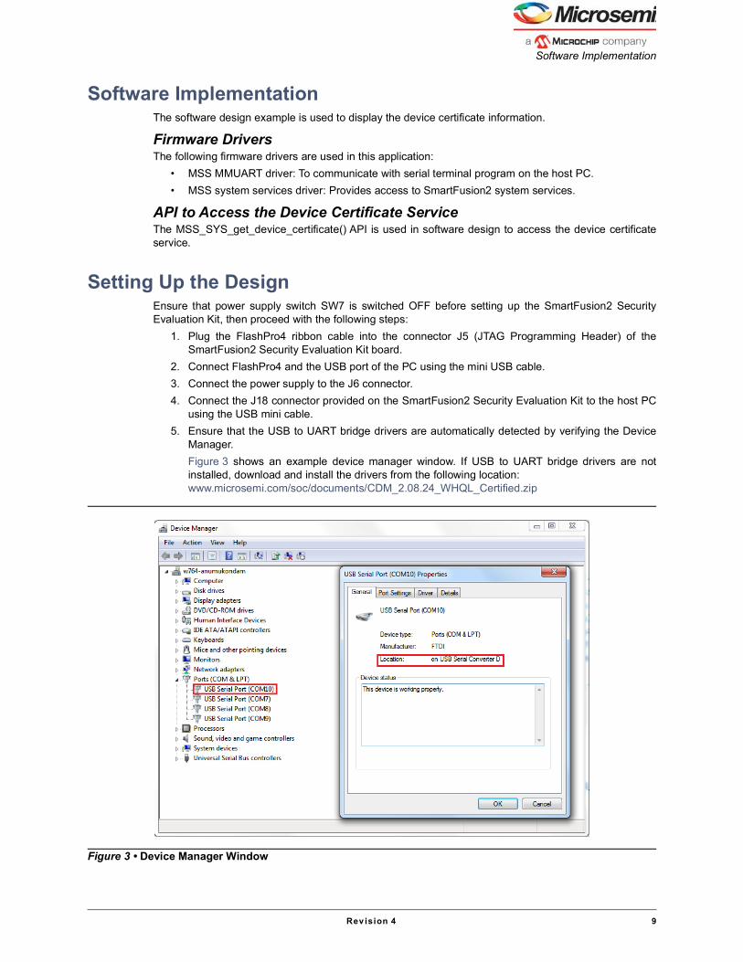
using the USB mini cable.5. Ensure that the USB to UART bridge drivers are automatically detected by verifying the Device
Manager.Figure 3 shows an example device manager window. If USB to UART bridge drivers are notinstalled, download and install the drivers from the following location:www.microsemi.com/soc/documents/CDM_2.08.24_WHQL_Certified.zip
Figure 3 • Device Manager Window
Using Device Certificate System Service in SmartFusion2 - Libero SoC v11.7
10 Rev ision 4
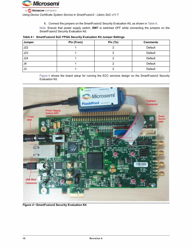
6. Connect the jumpers on the SmartFusion2 Security Evaluation Kit, as shown in Table 6.Note: Ensure that power supply switch, SW7 is switched OFF while connecting the jumpers on theSmartFusion2 Security Evaluation Kit.
Figure 4 shows the board setup for running the ECC services design on the SmartFusion2 SecurityEvaluation Kit.
Table 6 • SmartFusion2 SoC FPGA Security Evaluation Kit Jumper Settings
Jumper Pin (From) Pin (To) Comments
J22 1 2 Default
J23 1 2 Default
J24 1 2 Default
J8 1 2 Default
J3 1 2 Default
Figure 4 • SmartFusion2 Security Evaluation Kit

Running the Design
Revision 4 11
Running the DesignThe following steps describes how to run the design on the SmartFusion2 Security Evaluation Kit boardusing the M2S090TS-1FGG484 device:
1. Switch ON the power supply switch, SW7.2. Start a PuTTY session with 115200 baud rate, 8 data bits, 1 stop bit, no parity, and no flow control.
Use any free serial terminal emulation program such as: HyperTerminal or TeraTerm, if thecomputer does not have the PuTTY program. For more information about configuringHyperTerminal, TeraTerm, or PuTTY, refer to the Configuring Serial Terminal Emulation ProgramsTutorial.
3. Program the SmartFusion2 Security Evaluation Kit board with the provided STAPL file usingFlashPro4. Refer to "Appendix A: Design and Programming Files" on page 17 for moreinformation.
4. After programming, press the reset switch, SW6 (DEVRST), then HyperTerminal displays amessage and the device certificate information, as shown in Figure 5.
Figure 5 • Device Certificate in Hexadecimal Format (also known as base 16 or hex)

Using Device Certificate System Service in SmartFusion2 - Libero SoC v11.7
12 Rev ision 4
Viewing Fields in Device CertificateThe SmartFusion2 device certificates are encoded in the ASN.1 format. To view the content, thecertificates need to be decoded to a user readable format. The content of a device certificate can bedecoded in many ways, such as:
• Use windows utility certutil.exe• Use open source or other third-party online tools
For more information about how to decode device certificate using ASN.1 JavaScript decoder online tool,refer to "Appendix B: Decoding Device Certificate Using ASN.1 JavaScript Decoder Open Source Tool"on page 18.This application note uses the certutil.exe windows command tool utility to decode the devicecertificate. The following steps describe how to decode the device certificate:
1. Copy the device certificate HEX values (768 bytes) from the serial terminal program(PuTTY/HyperTerminal) to a text file. For example, copy the device certificate HEX values to theDC_HEX.txt file and save the file in the C\D\E: drive.
2. Remove the Padded tailing zeros inserted at the end of the device certificate. Note: The actual device certificate length can be found from 3rd and 4th bytes of the certificate, for
example in this case the total certificate length is 0x02e9 (3rd and 4th bytes value) + 0x4 i.e. 745+4= 749 bytes. so remove the last 15 bytes (768-749) of padded zeros from the certificate.
3. Open the command prompt window and type the commandE:\>certutil.exe -asn E:\DC_HEX.txt and click Enter key.
4. The command prompt displays the decoded device certificate in a user readable format.The device certificate fields are highlighted in Figure 6 on page 13, Figure 7 on page 14, Figure 8 onpage 15, and Figure 9 on page 16.

Running the Design
Revision 4 13
Figure 6 shows the device certificate - screen 1.
The following is the description of labels in Figure 6:Version Information
1. Version Number: 02Serial Number Information
2. Certificate Serial Number: 40 c9 39 5e 32 b1 01 33 63 15 3c a4 ae 08 55 c3 da 01Algorithm ID Information
3. Algorithm ID: SHA512ECDSAIssuer Information
4. Country / Region: US5. Organizational Unit: SoC6. Organization: MSCC7. Common Name: 6967463646c47674f27e used to point to the public key for signature check.
Validity informationNot Before
8. 12/1/2012 5:30 AMNot After
9. 12/31/2199 5:30 AM
Figure 6 • Device Certificate - Screen 1

Using Device Certificate System Service in SmartFusion2 - Libero SoC v11.7
14 Rev ision 4
Figure 7 shows the device certificate - screen 2.
The following is the description of labels in Figure 7:Subject Information
10. Rev (Generation Qualifier) 4 bytes fixed length: “1 ”11. Family (Surname): “ SmartFusion2”12. Product ID 33 characters (Given name): “ M2S090 ”
Subject Public KeyPublic Key Algorithm Information
13. ECC14. ECDSA_P384
Subject Public Key information15. 96 Byte ECC public key
Issuer Unique Identifier16. 9 byte bit string: 00 c1 93 d0 b2 cf 6b 40 00
Subject Unique Identifier17. (0x00+Factory Serial Number + Serial Number Modifier): 00 a5 54 aa 38 fd fc 34 b3 7a ae 36 33
07 cc 10 38
Figure 7 • Device Certificate - Screen 2

Running the Design
Revision 4 15
Figure 8 shows the device certificate - screen 3.
The following is the description of labels in Figure 8:Extension Information
18. Object ID 1.3.6.1.4.1.40676.1.0: padding19. 91 bytes zero padding20. Object ID 1.3.6.1.4.1.40676.1.1: Date code21. Date code value: 36 32 34 3122. Object ID 1.3.6.1.4.1.40676.1.2: Temp, Speed, and Voltage Grade23. Temp, Speed, and Voltage Grade <Generic Field Value>: ff ff ff ff ff ff ff ff ff ff ff ff ff ff 00 0024. Object ID 1.3.6.1.4.1.40676.1.3: Reserved25. Reserved26. Object ID 1.3.6.1.4.1.40676.1.4: Reserved27. Reserved28. Object ID 1.3.6.1.4.1.40676.1.10: Certificate Validator. This field is used by the Libero
SoC/Flashpro software to validate the Device certificate29. Certificate Validator Value (256 bit validator): “00 31 f0 ab f6 6c 0a 63 c5 27 ef 1f 12 8e 5a 20 8a
a8 6c c0 b8 3e 12 ec 19 d0 87 51 1f e0 7c 45”
Figure 8 • Device Certificate - Screen 3

Using Device Certificate System Service in SmartFusion2 - Libero SoC v11.7
16 Rev ision 4
Figure 9 shows the device certificate - screen 4.
The following is the description of labels in Figure 9:Certificate Signature Algorithm Information
30. Algorithm: sha512ECDSA (Object ID 1.2.840.10045.4.3.4)Certificate Signature Information: As shown in Figure 9, the highlighted circles 31 and 32 display thecertificate signature that is stored in the bit string format.
ConclusionThis application note describes how to implement the device certificate using the system services in theSmartFusion2 SoC FPGAs and view the content of the device certificate.
Figure 9 • Device Certificate - Screen 4

Appendix A: Design and Programming Files
Revision 4 17
Appendix A: Design and Programming FilesDownload the design files from the Microsemi SoC Products Group website:http://soc.microsemi.com/download/rsc/?f=m2s_ac436_liberov11p7_df The design file consists of Libero SoC Verilog project, SoftConsole software project, and programmingfiles (*.stp) for the SmartFusion2 Security Evaluation Kit board. Refer to the Readme.txt file included inthe design file for the directory structure and description.Download the programming files from the Microsemi SoC Products Group website:http://soc.microsemi.com/download/rsc/?f=m2s_ac436_liberov11p7_pf The programming file consists of STAPL programming fle (*.stp) for the SmartFusion2 SecurityEvaluation Kit board.

Using Device Certificate System Service in SmartFusion2 - Libero SoC v11.7
18 Rev ision 4
Appendix B: Decoding Device Certificate Using ASN.1 JavaScript Decoder Open Source Tool
ASN.1 JavaScript decoder is a web tool capable of parsing and showing any valid ASN.1 DER or BERdata structure as both a tree and a cross-linked hex-dump.
1. Open any standard web browser (for example, Internet Explorer) and enter the following URL inthe address bar: http://lapo.it/asn1js/#ASN.1 online decoder page is displayed, as shown in Figure 10.
2. Click clear.
3. Copy the 768 Bytes HEX format device certificate from any serial terminal program and paste it inthe online decoder, as shown in the Figure 11.
4. Click decode.
Figure 10 • Online Decoder

Appendix B: Decoding Device Certificate Using ASN.1 JavaScript Decoder Open Source Tool
Revision 4 19
Figure 11 • Online Decoder with Decode Option

Using Device Certificate System Service in SmartFusion2 - Libero SoC v11.7
20 Rev ision 4
The following window is displayed.
The decoded certificate field values in a tree format are on the left and the HEX dump values are on theright.For more information about the decoded field values, refer to "Viewing Fields in Device Certificate" onpage 12.
Figure 12 • Decoded Device Certificate

List of Changes
Revision 4 21
List of ChangesThe following table shows the important changes made in this document for each revision.
Revision* Changes Page
Revision 4(May 2020)
Information about device certificate description was updated. N/A
Revision 3(April 2016)
Updated the document for Libero SoC v11.7 software release (SAR 78039). N/A
Revision 2(October 2015)
Updated the document for Libero SoC v11.6 software release (SAR 71682). N/A
Revision 1(February 2015)
Initial release. N/A
Note: *The revision number is located in the part number after the hyphen. The part number is displayed at the bottomof the last page of the document. The digits following the slash indicate the month and year of publication.

51900304-4/05.20
Microsemi HeadquartersOne Enterprise, Aliso Viejo,CA 92656 USAWithin the USA: +1 (800) 713-4113 Outside the USA: +1 (949) 380-6100Sales: +1 (949) 380-6136Fax: +1 (949) 215-4996Email: [email protected]
©2020 Microsemi, a wholly owned subsidiary of Microchip Technology Inc. All rights reserved. Microsemi and the Microsemi logo are registered trademarks of Microsemi Corporation. All other trademarks and service marks are the property of their respective owners.
Microsemi makes no warranty, representation, or guarantee regarding the information contained herein or the suitability of its products and services for any particular purpose, nor does Microsemi assume any liability whatsoever arising out of the application or use of any product or circuit. The products sold hereunder and any other products sold by Microsemi have been subject to limited testing and should not be used in conjunction with mission-critical equipment or applications. Any performance specifications are believed to be reliable but are not verified, and Buyer must conduct and complete all performance and other testing of the products, alone and together with, or installed in, any end-products. Buyer shall not rely on any data and performance specifications or parameters provided by Microsemi. It is the Buyer’s responsibility to independently determine suitability of any products and to test and verify the same. The information provided by Microsemi hereunder is provided “as is, where is” and with all faults, and the entire risk associated with such information is entirely with the Buyer. Microsemi does not grant, explicitly or implicitly, to any party any patent rights, licenses, or any other IP rights, whether with regard to such information itself or anything described by such information. Information provided in this document is proprietary to Microsemi, and Microsemi reserves the right to make any changes to the information in this document or to any products and services at any time without notice.
About MicrosemiMicrosemi, a wholly owned subsidiary of Microchip Technology Inc. (Nasdaq: MCHP), offers a comprehensive portfolio of semiconductor and system solutions for aerospace & defense, communications, data center and industrial markets. Products include high-performance and radiation-hardened analog mixed-signal integrated circuits, FPGAs, SoCs and ASICs; power management products; timing and synchronization devices and precise time solutions, setting the world's standard for time; voice processing devices; RF solutions; discrete components; enterprise storage and communication solutions, security technologies and scalable anti-tamper products; Ethernet solutions; Power-over-Ethernet ICs and midspans; as well as custom design capabilities and services. Learn more at www.microsemi.com.