Embed Size (px)
Citation preview

Insight Vol XX No X Month 2013 1
MARINE COMPOSITES
Current methods of estimating the behaviour of marine composite structures under pressure due to slamming as a result of high waves are based on trial and error or oversimplification. Normally under these conditions the non-linearities of these structures are often neglected and, in order to compensate, an overestimated safety factor is employed. These conservative approaches can result in heavier and overdesigned structures. In this paper, a new semi-empirical method is proposed that overcomes some of
these problems. This work involved the use of an artificial neural network (ANN) combined with strain gauge data to enable real-time in-service load monitoring of large marine structural panels. Such a tool has other important applications, such as monitoring slamming or other transient hydrostatic loads that can ultimately affect fatigue life. To develop this system, a glass fibre-reinforced polymer (GFRP) composite panel was used due to its potential for providing a non-linear response to pressure or slamming loads. It was found that the ANN was able to predict normal loads applied at different locations on the panel accurately. This method is also capable of predicting loads on the marine structure in real time.
Keywords:Composite, marine, artificial intelligence, artificialneural network, structural analysis, load, non-linearstructures,largedisplacementanalysis.
1. IntroductionIn addition to hydrostatic and mass-related loads that can beevaluatedwithahighdegreeofaccuracyandconfidence,itisalsodesirabletomeasuretransientloadsduetoslammingasaresultofhighwaves.Thecurrentpracticetodeterminewaveloadsisbasedon applying standard rules, which often relies on conservativemethodsduetolargeuncertaintiesinthetheoreticaltreatmentusedforwaveloadpredictions.Thisleadstoacraftthatisheavierandslowerthanitcouldotherwisebe.
Althoughseahasanirregularandarbitrarycondition,theoverallconditioncanbepredictedstatisticallybysuperimposingaseriesofdifferentregularwavesofvaryingheights,lengths,directionsandphase[1-3].Inordertodefinethesea-statethatthecraftareexpectedto encounter during their lifetime, an enormous amount of dataregardingoceanwaveshasbeencollected.Hogbenet al[4]collectedcomprehensivedataregardingoceanwavesfrom104oceanareascoveringallmajorshippingroutes.Havingmoreinformationaboutsea states, thewave-induced loads on the craft structure and theresponsetosuchloadsmaybeestimated.
Techniques used to measure hydrodynamic loads use non-linear equations due to the random and irregular nature of thesea, resulting in a very expensive and time-consuming analysis.Methods have been developed in order to simplify such ananalysis[5].Striptheoryisoneofthemostwell-knowntechniquesusedtodeterminethewave-inducedloads[6,7].Theprincipleisthatthecraft’shullisdividedintoanumberofsegmentsorstrips.Theforces acting on the hull are then calculated separately on eachsegmentusingatwo-dimensionalflowtheory.Thismethodignoresthe longitudinal component of relative velocity and any type ofinteractionbetweenthedifferentsegments.Othershortcomingsofthis theory include ignoring three-dimensional or viscous effects
Using artificial neural networks and strain gauges for the determination of static loads on a thin square fully-constrained composite marine panel subjected to a large central displacement
M R Ramazani, S Noroozi, P Sewell, R Khandan and B CrippsSubmitted 19.07.12 Accepted 06.09.12
Mohammad Reza Ramazani received his MEng degree in mechanical engineering from the University of Birmingham in 2009. He is currently studying for a PhD jointly funded by Bournemouth University and BAE Surface Ships Ltd to investigate in-service load monitoring of marine structures. His interests include artificial intelligence and computer-aided engineering.
Professor Siamak Noroozi received his PhD from Sheffield University in 1986 in the area of finite element analysis coupled with boundary element analysis. He currently holds the Chair in Advanced Technology at Bournemouth University. His research interests are finite element analysis, boundary element analysis, biomechanics, condition monitoring, general stress analysis, photoelasticity, alternative numerical analysis, composite technology and aeroelasticity.
Dr Philip Sewell received his BEng degree in mechanical engineering from the University of the West of England in 1999 and a PhD in the field of prosthetic design in 2003. He is currently employed as a Senior Academic in Design Simulation at Bournemouth University. His research interests include the design of novel tools for prosthetic fitting, the development of techniques to determine prosthetic interfacial pressure distributions and experimental and numerical stress analysis.
Rasoul Khandan received his BSc degree in mechanical engineering from the Isfahan University of Technology in 2004 and an MSc in mechanical engineering (applied design) in 2008 from Shiraz University. He is currently working on modelling, simulation and optimisation of composite materials as a PhD researcher in the Design Simulation Research Centre at Bournemouth University. His main research interest is modelling and the application of composite and smart materials.
Professor Bob Cripps received his degree in ship science from the University of Southampton in 1976. He was awarded an Honorary Doctor of Engineering from Bournemouth University in 2005. He is currently a Director of Longitude Consulting Engineering, part of London Offshore Consultants (LOC). He is a Visiting Professor at Bournemouth University and a Royal Academy of Engineering Visiting Professor in the Principles of Engineering Design at the University of Southampton.
Mohammad Reza Ramazani*, Siamak Noroozi, Philip Sewell and Rasoul Khandan are with the School of Design, Engineering & Computing, Bournemouth University, Bournemouth, UK.
Bob Cripps is with Longitude Consulting Engineers Ltd, Southampton, UK.
*Corresponding author. Tel: 01202 961528; Email: [email protected]

aswellas theinability toaccountfor theabove-waterhullform.Inordertoresolvetheproblemwithcompatibilitybetweenstrips,flexible beam strip theorieswere developed that account for thebending and shear stiffness of the hull[8].Although this kind oftheorycanestimatethedistortionalhigherfrequencyresponsesofahulltoslammingandlashingexcitation,itisstilllinearanalysisandextremeresponseisnotwellmodelled.
The accuracy of the strip theory and other codes has beeninvestigatedby several researchers and the error associatedwithpredictingamid-shipbendingmomentusingstriptheoryisoftheorder of 10% to 20%.This accuracy is reduced further towardsthe ends of the vessel and as seas become progressively morebeam-on[9]. Clarke[10] conducted many on-board measurementsemployingseveralRoyalNavy(RN)ships.Theresults indicatedthat strip theory over-estimates wave bending moments,particularly at larger wave heights. Furthermore, the hoggingbending moment was over-predicted more so than the saggingmoment.Itisconcludedthatthesetechniquesareonlyaccurateformoderateseaconditionsandshipspeedsmeaninganextremeloadcausinga largedisplacement inpanels is impossible tomeasure.Moreover,doubtsalsoexistinmanyoftheassumptionsthatinvolvestochastic/random data or procedures involving environmentalandoperationalconditions.Thisisduetothefactthatsometimesenvironmental and operational conditions are difficult to defineaccuratelyinadvanceandthereforeassumptionsareneeded[11].
In order to improve the accuracy of estimation, especially inshort waves, many numerical methods considering the three-dimensional effects have been introduced.Among them are thethree-dimensionalGreen functionmethod[12] andRankine sourcemethod[13-15] based on three-dimensional potential theory. Thebenefits of these methods include taking the three-dimensionaleffects intoaccount,havinggoodstabilityofcomputationsandamoderatecomputingtime.Hence,theyareconsideredassuitabledesigntoolsreplacingthestripmethods.
A review by Phelps[9] indicates that non-linear theories andthree-dimensionalloadpredictionmethodshavebeenintroduced,but these require greater computational effort and have not yetproventobesignificantlymoreaccuratethanthetwo-dimensionalmethods. It is concluded that a novel technique is required toovercome current limitations in the practices used to measureandestimateloadsexperiencedbythehullofasmall,high-speedboatoperatinginaseaway.Furthermore,asvesselsandcraftare,inmost cases, extremely complicated structures, themechanicalproperties, or relationship between externally-induced excitationandstructuralresponses,aredifficulttoformulate.Anappropriateload monitoring system and technique has to be developed fornavalassetsandlargestructures[16].
A novel approach for the determination of pressure loadsexperienced by marine structures is the utilisation of artificialneuralnetworks(ANN)asaninversemethod.InastudybyCaoet al[16],anapproachwasdevelopedtoidentifytheloadsactingonaircraftwings,whereanANNwasutilisedtomodeltheload-strainrelationship for structural analysis. The research demonstratedthatusinganANNtoidentifyloadsisfeasibleandawell-trainedANNrevealsanextremelyfastconvergenceandahighdegreeofaccuracy in the process of load identification for a cantileveredbeam model. In a study byAmali et al[17], it is illustrated thatANN can be combined with experimental methods to create ahybrid inverse problem analysis tool or inverse problem engine.The hybrid approach can be applied to both direct problems(calculationof the structural response fromknown loadsappliedtothestructure)andinverseproblems(calculationof theappliedloadfromaknownstructuralresponse).Additionally,theapproachavoids theneed tohave informationon thecomponentgeometryandmaterialproperties[18,19].
Ramazani et al[20] have recently shown that the inverseproblemapproachcanbeusedtoestimatelowloadsappliedona
compositemarinepanelfromasmalldeflectionanditsassociatedstrain measurements.A comparison of theANN loads with theactual applied loads indicated a very good performance of themethodology.Thiswasachievedinrealtime,providinganaccurateloadhistoryforacomponentwithoutrequiringknowledgeofthematerialpropertiesorcomponentgeometry.However,alargeloadresultsinalargedisplacementinthepanel,wherethedisplacementisnolongerpredictable.Thisimpliesthatthesuperpositionmethodofgeneratingtrainingdataforasmalldisplacementcannolongerbe appliedhere.However,marine structuresdo experience largedisplacementandforthatreasonloadpredictionisessential.Thispaper reports on the research undertaken to further develop theANN methodology to quantify static pressure/central load on acompositemarinepanelfromitsnon-linearstructuralresponse.
2. MethodologyThemethodologyemployedtoevaluatethesuitabilityofanANNasaninverseproblemispresentedinthissection.AbackpropagationANN was designed, developed and trained within the Matlabsimulation environment (Mathworks, Natick, Massachusetts,USA)tomeasuretransverseloadonaflatcompositemarinepanel.Theestimatedoutputwas thenvalidatedbycomparing itagainstbothexperimentalandnumericaldata.
2.1 Inverse problem analysis methodologyInverse problem analysis is based on accurately calculating theexternalloadsorboundaryconditionsthatgenerateaknownstrainatpre-determinedlocationsonastructure.AnANN,asaninverseproblemsolver,canbeutilisedtodeterminearelationshipbetweenthecauseanditseffect[20].Inthisstudy,thestaticloads(thecause/output)onacompositepanelarequantifiedbyacquiringrepeatablestrain responses (the effect/input) to these loads from the panel.Introducing these examples to an ANN, the system can learnandformtherelationshipsbetweentheinput(strains)andoutput(load)throughthetransferfunction.TheANNrequiresanumberofknowninputandoutputdatafortraining(ierelatingtheANNinputstooutputsusingatransferfunctionandseriesofweightingvalues).OncetheANNissufficientlytraineditcanbeutilisedtoestimate the output in real time.New inputs (problemdata) canthenbepresentedandtheloadcanbeestimatedinrealtime.
2.2 Experimental set-upThestructureunderconsiderationwasa1m2glassfibre-reinforcedfibrepolymer/plastic(GFRP)marinecompositepanel(Figure1).ThesampleGFRPcompositepanelusedwasmadeofsevenlayersofstitchedbiaxial±45E-glassclothwithAmpreg22epoxyresinsystem,handlaid-upwithatotalthicknessof5×10–3m.Thefibreswerealignedparalleltotheedgesofthepanel.Table1showstheexperimentalmechanicalpropertiesoftheglassfibreasprovidedbythemanufacturer.
The panel was divided into a four-by-four grid producingsixteenequalregions,eachwithanareaof0.25×0.25m2(Figure
Figure 1. Schematic of composite panel indicating strain gauge and loading locations
2 Insight Vol XX No X Month 2013

Insight Vol XX No X Month 2013 3
1).Thebottomsurfaceofthepanelwassupportedonallfouredgesusingaluminiumbars,each0.0381mhigh,0.01905mwideand 1mlong.Sixteenlinearelectricalresistancestraingauges(ERSG)(S1-16)were bonded to the centre of each region (specificationinTable2).Twoeight-channelNIcDAQ9236modulesmountedon NI cDAQ 9174 chassis (National Instruments Corporation,Austin,Texas,USA)wereusedasthestrainmonitoringandcontroldata acquisition systemwith a resolutionof+/– 0.1microstrain.The systemprovides differential inputs tomonitor sixteen straingauges at up to 10,000 samples per second.The strain datawascollectedusingMatlab,utilisingMatlabDataAcquisitionToolboxcapabilities.
Table 2. Strain gauge specification
Type Generalpurposelineargauge
Resistance 350ohms±0.6%
Gaugefactor 2.100±0.5%
Gaugelength 6.35mm
Gaugewidth 2.54mm
Normal loads were randomly applied to the top surface ofthe panel at thirteen grid intersections (L1-13). Depending ontheproximityof thegauge to theapplied loads,differentgaugesexhibiteddifferentlevelsofsensitivity,whichwasasexpected.Toproduceefficient trainingdata thestraindatashouldbecapturedatthesensitiveregions(iethestrainatthoselocationsmustvarysignificantlyduetochangesinloadlevel).Inaddition, thestraindata collected must provide a unique response for each loaddistribution.Ifstrainiscollectedfromnon-sensitiveregionsofthepaneland/or thestraindatacollected isnotuniqueforeach loaddistribution theANN is less likely to be able to find a functionrelatingtheinputandoutput.
2.3 Generation of training dataMany smallmarine craft hulls aremanufactured fromfibreglassstrengthenedbywoodorfoam.Theircharacteristicsaresuchthattheirthicknessissmallcomparedtotheirotherdimensions.Inthisstudy, a GFRP panel has been utilised to represent a section ofthehull.Panelscanbeclassifiedaccordingtotheirthicknessandtheirlateraldeflectioncomparedtotheirthickness[21].Theycanbe
classified as: (1) thick plate, small deflection; (2) thin plate andsmall deflection; (3) thin plate, large deflection; or (4) very thinplate(membranes)witheithersmalldeflectionorlargedeflection.Inallcasesthesolutionsareapproximate,notexactorclosedform.ThedeflectionatthecentreofaplatesubjecttopressureisofferedbyWestergaardandSlater[22]andisbasedonthemodifiedflexuretheoryofplateswhere,dependingontheplateaspectratio,edgeboundary conditions and load, different approximate empiricalsolutionsarefound.Insuchcases,asmalldisplacementisdefinedasdisplacementlessthanorequaltohalfthethicknessoftheplate.Ifthedisplacementexceedsthislimitthentheproblemistreatedasanon-linearproblemwherethedisplacementcannolongerbeaccuratelypredictedusingtheabovetheory.Thisisduetohighlynon-lineardoublecurvaturedeformation,unlikethedisplacementfunctionstatedabove.Inlargedisplacementanalysis,thetransverseshearcanalsonolongerbeignoredandifthepaneliscompositethen the transverse shear requires further special treatment. Insuchcases, theclassical inverseapproachusedpreviously,basedonutilisingdata generated from superposition, canno longer beemployedduetothecomplexityofthedisplacementfunction.
Fornon-linearstructuresanalternativeapproach isneeded inorder togenerate the required trainingdata.There are twowaysinwhich such data can be generated: (a) experimentally; or (b)usinganon-linearfiniteelementanalysis(FEA)solver.Generatingtherequiredtrainingdataexperimentallyisverytimeconsumingand labour intensive.Therefore,non-linearFEAanalysisusingascriptthatallowedautomaticgenerationofarandomloadonthepanelwasutilisedtogeneratethetrainingdata.Abaqus6.10-1FEAsoftware (Dassault SystèmesSimuliaCorp,Rhode Island,USA)wasused.AscriptfunctionwritteninPythonlanguagewasusedtoiterativelyrunthesoftwareinabatchusingdifferentrandomloadsappliedateachofthethirteenloadinglocationsonthepanel.TheFEAmodelwasinitiallyvalidatedtoensurethatitrepresentedtheactualpanelaccurately.Thevalidationwasachievedbycomparingstrains collected experimentally with the FEA strains under thesameloadingconditions.Loadsfrom100Nto800Nappliedin100NincrementswereplacedonthepaneloneatatimeatlocationsL1toL13.ThestrainreadingsatlocationsS1toS16onthepanelweresavedforeachtest.ThesametestswereperformedwithFEAtocomparewiththeexperimentalresults.
Once validated, a large number of training (load/strain
Table 1. Panel material specification provided by SP Gurit Systems (Newport, Isle of Wight, UK)
Materialname XE905
Materialtype Stitchedbiaxial
Fibrevolumefraction 0.46
Longitudinalproperty Units Units
Longitudinaltensilemodulus N/mm2 21220 Poisson’sratio(longitudinalstrain) 0.120
Longitudinaltensilestrength N/mm2 318.3 Poisson’sratio(transversestrain) 0.120
Longitudinalcompressivemodulus N/mm2 21220 Longitudinalcoeff.ofthermalexpansion 10-6/°K 14.62
Longitudinalcompressivestrength N/mm2 254.6 Transversecoeff.ofthermalexpansion 10-6/°K 14.62
Transverseproperty Density kg/m3 1786
Transversetensilemodulus N/mm2 21220 Structuralplythickness mm 0.75
Transversetensilestrength N/mm2 318.3 Actualplyweight g/m2 1364
Transversecompressivemodulus N/mm2 21220 Shearthickness mm 0.75
Transversecompressivestrength N/mm2 254.6
Shearproperties Derivedshearproperties@±45°
Interlaminarshearmodulus N/mm2 3050 Shearmaterialname 1xXE905@±45°
Interlaminarshearstrength N/mm2 36.6 Axialmoduluswithfibres@±45° N/mm2 9737
In-planeshearmodulus N/mm2 3050 Shearmoduluswithfibres@45° N/mm2 9471
In-planeshearstrength N/mm2 46.1 Poisson’sratiowithfibres@±45° 0.596

response)datawasable tobegeneratedfromtheFEAmodel.Inorder to increase the efficiency of generating the training data,itwaspossible to reduce thenumberofFEAmodels required toestablish the non-linear strain response for each gauge location.Thiswasachievedbyfittingnon-linearcurvestodatacollectedforeachstrainlocationandusingthecurvestointerpolatestraindatafordifferentloadmagnitudes.
The structural responses of the panel in terms of strainweresavedtobeusedastheinputtrainingdataset.Thecorrespondingloadforeachinputdatasetwasalsosavedandutilisedastheoutputtrainingset.Someoftheseinputandoutputsweresavedseparatelyfortestingthenetworkanderrorminimisation.Inthisstudy,sixteensingle strain gauge readings (inputs) and thirteen applied loads(outputs)constituteonetrainingdataset.Ateachloadinglocation(L1-L13),astaticloadrangingbetween24.525Nand784.8Nwasappliedinstepsof24.525N.Intotal,1040trainingdatasetsweregeneratedfromthenon-linearFEAmodel.
2.4 ANN architecture/topologyANN analysis often requires a high number of individual loopsto determine the best solution. However, the training time canbe reduced(ie reduce thenumberof loops tominimise theerrorequation)bypre-processing thedata that isgivento thenetworktotrain.Havingmultiplehiddenlayersofneuronswithnon-lineartransferfunctions(suchastan-sigandlog-sig)enablesthenetworkto understand both non-linear and linear relationships betweeninputandoutputdata.UnsatisfactoryperformanceoftheANNcanbeduetoawiderangeofreasons,suchas:q anunsuitableANNarchitectureorlearningmethod;q insufficientrepresentativedata(notenoughexamplestrain/load
data);q inadequate pre-processing (noisy data from data acquisition
systemignored);q unsuitableANNtrainingparameters.
MostofthetimethisisnotthecaseandtheANNwillbewelltrainedandperformsatisfactorily,evenonanewuntraineddataset.Key architectural issues that can be optimised include: (i) thenumberoflayersintheANN;(ii)thenumberofneuronsperlayer;(iii)thetypeandparametersoftheneuron,whichareusuallythesamethroughout;and(iv)thenumberofcalculationsperiterationduringlearningandrecall.
TheMatlabArtificialNeuralNetwork toolboxwas used in thisstudytogeneratetwodifferentbackpropagationANNarchitecturesinordertocomparetheirperformance.Thearchitecturesutilisedwere:q Onenetworkwithsixteenneuronsintheinputlayerandthirteen
neuronsintheoutputlayeristrainedtoestimatetheloadonthepanelfromthestrainresponses(Figure3).
q Thirteennetworkseachwithsixteenneurons in the input layerandoneneuronintheoutputlayeraretrainedandusedtoestimatetheloadonthepanelfromthestrainresponses(Figure4).
Thenumberofhiddenlayersandneuronsin each hidden layer of the two networkarchitectures were flexible. These weredependentonthecomplexityofthetrainingdatasetsandwereoptimisedaccordingtothenetwork performance. The sum of squarederrors (SSE) and mean of squared errors(MSE) are common network performanceindicators. Through the testing of variousnetworkarchitectures,theoptimumnetworkhavingthelowestperformanceindicatorcanbedetermined.Once theANN is trained, itcan be employed to estimate new loadingcases where the same patterns exist. Inother words, whenever the same pattern of
strainreadingasaninput is introducedtothenetwork, itwillbeable to estimate the loads that caused those structure responses.Dependingonhowwellthenetworkistrained(theperformanceofthenetwork),therewillbeanerrorbetweentheoutputdatasetandthenetworkestimatedoutput(load).
2.5 ANN validation and performanceThevalidityandperformanceoftheANNmethodwasevaluatedbycomparing the loadestimatedby theANNwithknown loadsappliedto thepanel,whichwerenotseenbythenetworkduringthe training process. The first validation study utilised load andstraindatageneratedfromtheFEAmodelandwascomparedwithestimatedloadsfromtheANN.Inthesecondstudy,problemstraindatawascaptureddirectlyfromthepanelandagaintheestimatedloadswerecomparedwiththeactualappliedloads.
3. ResultsThe validity of utilising FEA for training data generation andtheANNvalidity and performance are detailed in the followingsections.
3.1 FEA model validationFigure 2 indicates that for loading only location L13, there isreasonableagreementbetweenthestrainreadings(S6andS10)ofFEAtestsandexperimentaltests.Theaveragepercentageerrorislessthan7%.TheseresultsindicatethattheFEAmodelcanbeusedconfidentlytosimulatevariousloadingconditionsandtogeneratetherequiredtraininginputdata.
3.2 ANN validation and performanceAsmentionedinSection2.4,twodifferentmethodsareemployedtodefine thenetworks.Table3 lists themajorparametersof thenetworkarchitectureusedinthetwomethods.Itwasdetermined,
Table 3. ANN architectures
1networkwith16straininputsand13loadoutputs
13networkseachwith16straininputsand1loadoutput
Numberofnetworks 1 13
Architecture Feedforwardbackpropagation
Numberoflayersineachnetwork 2 1
Rangeofloadestimation 24.525-784.8(N) 24.525-784.8(N)
Noofinputs(surfacestrains) 16 16
Noofoutputlayerneurons(loads) 13 1
Noofeachhiddenlayerofneurons [2020] [50]
Numberoftrainingpatterns 1040 1040
Numberoftestingpatterns 1040 1040
Figure 2. Comparison of FEA and experimental data of selected strain gauges
4 Insight Vol XX No X Month 2013
Insight Vol XX No X Month 2013 5
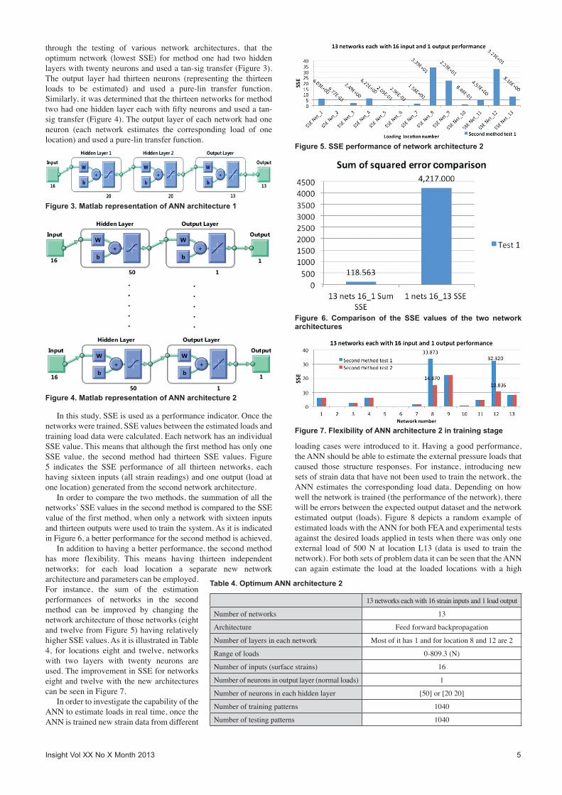
through the testing of various network architectures, that theoptimumnetwork (lowest SSE) formethod one had two hiddenlayerswithtwentyneuronsandusedatan-sigtransfer(Figure3).The output layer had thirteen neurons (representing the thirteenloads to be estimated) and used a pure-lin transfer function.Similarly,itwasdeterminedthatthethirteennetworksformethodtwohadonehiddenlayereachwithfiftyneuronsandusedatan-sigtransfer(Figure4).Theoutputlayerofeachnetworkhadoneneuron (each network estimates the corresponding load of onelocation)andusedapure-lintransferfunction.
Inthisstudy,SSEisusedasaperformanceindicator.Oncethenetworksweretrained,SSEvaluesbetweentheestimatedloadsandtrainingloaddatawerecalculated.EachnetworkhasanindividualSSEvalue.ThismeansthatalthoughthefirstmethodhasonlyoneSSE value, the second method had thirteen SSE values. Figure5 indicates the SSE performance of all thirteen networks, eachhavingsixteeninputs(allstrainreadings)andoneoutput(loadatonelocation)generatedfromthesecondnetworkarchitecture.
Inordertocomparethetwomethods,thesummationofallthenetworks’SSEvaluesinthesecondmethodiscomparedtotheSSEvalueofthefirstmethod,whenonlyanetworkwithsixteeninputsandthirteenoutputswereusedtotrainthesystem.AsitisindicatedinFigure6,abetterperformanceforthesecondmethodisachieved.
Inadditiontohavingabetterperformance,thesecondmethodhas more flexibility. This means having thirteen independentnetworks; for each load location a separate new networkarchitectureandparameterscanbeemployed.For instance, the sum of the estimationperformances of networks in the secondmethod can be improved by changing thenetworkarchitectureofthosenetworks(eightandtwelvefromFigure5)havingrelativelyhigherSSEvalues.AsitisillustratedinTable4, for locations eight and twelve, networkswith two layers with twenty neurons areused.TheimprovementinSSEfornetworkseightand twelvewith thenewarchitecturescanbeseeninFigure7.
InordertoinvestigatethecapabilityoftheANNtoestimateloadsinrealtime,oncetheANNistrainednewstraindatafromdifferent
loadingcaseswereintroducedtoit.Havingagoodperformance,theANNshouldbeabletoestimatetheexternalpressureloadsthatcaused those structure responses. For instance, introducing newsetsofstraindatathathavenotbeenusedtotrainthenetwork,theANN estimates the corresponding load data.Depending on howwellthenetworkistrained(theperformanceofthenetwork),therewillbeerrorsbetweentheexpectedoutputdatasetandthenetworkestimated output (loads). Figure 8 depicts a random example ofestimatedloadswiththeANNforbothFEAandexperimentaltestsagainstthedesiredloadsappliedintestswhentherewasonlyoneexternal loadof500Nat locationL13 (data isused to train thenetwork).ForbothsetsofproblemdataitcanbeseenthattheANNcan again estimate the load at the loaded locations with a high
Table 4. Optimum ANN architecture 2
13networkseachwith16straininputsand1loadoutput
Numberofnetworks 13
Architecture Feedforwardbackpropagation
Numberoflayersineachnetwork Mostofithas1andforlocation8and12are2
Rangeofloads 0-809.3(N)
Numberofinputs(surfacestrains) 16
Numberofneuronsinoutputlayer(normalloads) 1
Numberofneuronsineachhiddenlayer [50]or[2020]
Numberoftrainingpatterns 1040
Numberoftestingpatterns 1040
Figure 3. Matlab representation of ANN architecture 1
Figure 4. Matlab representation of ANN architecture 2
Figure 5. SSE performance of network architecture 2
Figure 6. Comparison of the SSE values of the two network architectures
Figure 7. Flexibility of ANN architecture 2 in training stage

degreeofaccuracy.However,theerrorsizeofestimatedloadswiththeANNforexperimentaltestsisslightlybigger.SuchasmallerrorisnormalanditcouldbefromaninitialerrorbetweentheFEAdataandexperimentaldata,errorsinducedfromtherepeatabilityofthedataacquisitionsystemwitharesolutionof+/–0.1microstrainaswellaspossibleovertrainingoftheANN.
The estimated negative load values at the unloaded locationswere due to the differences between the strain data collected togenerate the training data and the collected problem strain data.Duetotheseerrors,slightlydifferentstrainpatternsareintroducedto the ANN producing the errors in the estimated loads. Theintroductionof furthernoisypatterns in the trainingdatasetmayreduce these small errors, indicating that further work could becarriedouttoimprovetheaccuracyfurther.
4. DiscussionInthisstudy,itisshownthattheinverseproblemmethod,utilisinganANN, is capableof estimatingmagnitudeandpositionof thestatic pressure loads on a marine composite panel under largedisplacementfromnon-linearstrainmeasurements.Theresultsofthisstudycanbesummarisedasfollows:q FEAdatacanbeusedtogeneratetrainingdataforANNinverse
loadestimationproblems.q TwodifferentANNarchitecturesareusedandtheperformances
arecompared.q Havingnon-linear relationshipsbetween theapplied loadand
thesurfacestrains,thesystemalwaysconvergesandtheSSEisintherangeofacceptableerror.
q Thesystemiscapableofestimatingthepositionandmagnitudeofstaticpressureloadsonamarinecompositepanelunderlargedisplacement.
q Havingalargedifferencebetweenthetrainingdatasetsandtheproblem datasetmakes theANN unable to estimate the loadaccurately.
q ThemainsourceoferrorwasfoundtobeaninitialerrorbetweentheFEAdataandexperimentaldata.
Theabilitytomeasuretheactualloadhistoryofacraftin-servicewould enable the designer to validate the load estimation andstructuraldesigntoolsusedduringthedesignstageofacraft.Thiswouldleadtothedevelopmentofmoreoptimalstructuredesignsfor this typeofcraft.Theoperationalsafetyof thecraftcanalsobeimprovedbyhavingareal-timeloadmonitoringsystemthatisabletodetectanydegradationofthestructuralintegrityanddefectswithinthestructure.
ItisproposedthattheANNmethodology,withfurtherresearchand development, could be utilised for the quantification ofin-service,transientloadsinreal-timeactingonthecraftfromthecraft’s structural response (strain response to load). This wouldprovide valuable information to influence future craft design. Inorder to fully evaluate the proposedmethodology for in-serviceloadmonitoringofmarinestructures, thefollowingareasrequireinvestigation:q The behaviour of marine structures under transient load
conditions(dynamicloadisapplied).q Theeffectof thesizeof thestructureon theANNestimation
accuracy.q Thenumberofsensorsrequiredforaccurateloadestimationby
optimisingthemethod.Whilesomevesselsdohaveintegratedsensorsmostdonot.Thenumberofsensorsshouldbeminimisedtoreducethetimetotrainthesystem,costandweight.
q TheeffectofmodifyingANNtrainingparameters,includingthenumberandtypeoftrainingpatternsintroducedtotheANN.
q Validationofthemethodologyonacraftin-service.
Finally,agraphicaluser interface (GUI)shouldbedevelopedallowingcontrolofvariousparametersofthedataacquisitionandloadmonitoringsystem,aswellasgraphicaldisplayinrealtime.
5. ConclusionsIthasbeenshownthattheinverseproblemapproachcanbeusedtoestimatethemagnitudeandpositionofstaticpressureloadsona marine composite panel under large displacement from non-linearstrainmeasurements.AcomparisonoftheANNloadswiththeactualappliedloadsindicatedaverygoodperformanceofthemethodology.Thiswasachievedinrealtime,providinganaccurateloadhistory.Thispotentiallymakes the system ideal for solvingmany classes of complex engineering problem that require loadmonitoring.
References1. WJPierson,‘Aunifiedmathematicaltheoryfortheanalysisof
propagation and refraction of storm-generated ocean surfacewaves’,partiandii,NewYorkUniversity,NewYork,1952.
2. M St Denis andW J Pierson, ‘On the motions of ships inconfusedseas’,SNAMETransactions,Vol61,1953.
3. WJPierson,GNeumannandRWJames,‘Practicalmethodsforobservingandforecastingoceanwavesbymeansofwavespectraandstatistics’,HydrographicOfficePublication,1955.
4. NHogben,NMCDacunha andGFOlliver,GlobalWaveStatistics,UnwinBrothersLtd,UK,1986.
5. YBai,MarineStructuralDesign,ElsevierScienceLtd,Oxford,2003.
6. B V Korvin-Kroukovsky, ‘Investigation of ship motions inregular waves’, SNAME Transactions, Vol 63, pp 386-435,1955.
7. J Gerritsma and W Beukelman, ‘The distribution of the
Figure 8. ANN estimation for FEA and experimental data versus expected real data
6 Insight Vol XX No X Month 2013

Insight Vol XX No X Month 2013 7
hydrodynamicforcesonaheavingandpitchingshipmodelinstillwater’,paperpresentedattheFifthSymposiumonNavalHydrodynamics,Washington,1964.
8. R E D Bishop and W G Price, Hydroelasticity of Ships,CambridgeUniversityPress,Cambridge,1979.
9. BPPhelps, ‘Determinationofwave loadsforshipstructuralanalysis’, DSTO Aeronautical and Maritime ResearchLaboratory,Melbourne,1997.
10. J D Clarke, ‘Wave loading of warships’, Journal of NavalScience,Vol12,No4,1986.
11. T Kukkanen, ‘Wave load predictions formarine structures’,Rakenteiden Mekaniikka (Journal of Structural Mechanics),Vol43,No3,pp150-166,2010.
12. H Iwashita, A Ito, T Okada, M Ohkusu, M Takaki and SMizoguchi,‘Waveforceactingonabluntshipwithforwardspeed inoblique sea’, Journal ofSocietyNavalArchitectureJapan,Vol176,1994.
13. D Nakos and P Sclavounos, ‘Ship motions by a three-dimensional rankine panel method’, paper presented at theProceedings of 18th Symposium on Naval Hydrodynamics,AnnArbor,1990.
14. KTakagi,‘Calculationofunsteadypressurebyrankinesourcemethod’,JournalofKansaiSocietyofNavalArchitecture,Vol219,pp47-56,1993.
15. HYasukawa, ‘A rankinepanelmethod to calculateunsteadyship hydrodynamic forces’, Journal of Society NavalArchitecture,Vol168,pp131-140,1990.
16. XCao,Y Sugiyama andYMitsui, ‘Application of artificialneural networks to load identification’, Computers &Structures,Vol69,pp63-67,1998.
17. R Amali, S Noroozi and J Vinney, ‘The application ofcombinedartificialneuralnetworkandfiniteelementmethodindomainproblems’,paperpresentedattheSixthInternationalConferenceonEngineeringApplicationsofNeuralNetworks(EANN2000),KingstonuponThames,2000.
18. R Amali, S Noroozi, J Vinney, P Sewell and S Andrews,‘Predictinginterfacialloadsbetweentheprostheticsocketandthe residual limb for below-knee amputees – a case study’,Strain,Vol42,pp3-10,2006.
19. P Sewell, S Noroozi, J Vinney, R Amali and S Andrews,‘Improvementsintheaccuracyofaninverseproblemengine’soutput for the prediction of below-knee prosthetic socketinterfacial loads’, Engineering Applications of ArtificialIntelligence,Vol23,pp1000-1011,2010.
20.M R Ramazani, S Noroozi,MKoohgilani, B Cripps and PSewell, ‘Determination of static pressure loads on amarinecompositepanel fromstrainmeasurementsutilising artificialneuralnetworks’, submitted toProceedingsof the Institutionof Mechanical Engineers, Part M: J Eng for the MaritimeEnvironment,1475090212449231,firstpublishedon25June2012,doi:10.1177/1475090212449231
21. A P Boresi, R J Schmidt and O M Sidebottom, AdvancedMechanicsofMaterials,FifthEdition,JohnWiley,1993.
22. HMWestergaardandWASalter, ‘Momentsandstresses inslabs’,ProceedingsofAmerConcreteInst,Vol17,pp415-538,1921.