Embed Size (px)
Citation preview
1
Using Architecture Analysis for Mission Capability Acquisition
Dr. Charles DickersonAssistant Secretary of the Navy for Research, Development and Acquisition
Chief Engineer of the Navy (ASN (RDA) CHENG)Director of Architecture
Three Crystal Park2231 Crystal Drive, Suite 1000
Arlington, VA 22202-3748
CAPT (USN Ret) Steve SoulesBooz Allen and Hamilton Inc.
Crystal Square TwoSuite 1100
1725 Jefferson Davis HighwayArlington , Va. 2202-4158
Track: C2 Transformation Through Experimentation
C2 Assessment Tools & Metrics
2
Using Architecture Analysis for Mission Capability Acquisition
Dr. Charles DickersonAssistant Secretary of the Navy for Research, Development and Acquisition
Chief Engineer of the Navy (ASN (RDA) CHENG)Director of Architecture
Three Crystal Park2231 Crystal Drive, Suite 1000
Arlington, VA 22202-3748
CAPT (USN Ret) Steve SoulesBooz Allen and Hamilton Inc.
Crystal Square TwoSuite 1100
1725 Jefferson Davis HighwayArlington , Va. 2202-4158
Abstract
Historically, the DoD Architecture Framework has been used for designing new systems.Recently though, architectural work that was developed for Fleet Battle Experiment India(FBE I) was used to define the framework for the Mission Capability Package (MCP) forNaval Time Critical Targeting (TCT). The architecture products were used to describe,assess and choose investment strategies leading to a more capable and efficientintegration of systems that would produce the desired mission capability. The resultinganalysis provided insights for improving the networking of sensors C2 and weaponssystems. Additionally, the architecture methods also provided insights on particular areasof the architecture where there might be system duplications and gaps in executing theactivities required by the operators.
This paper summarizes an architectural methodology that can be used to enable acapabilities based approach to the planning and acquisition of DOD families of systems(FoS) that must interoperate with each other in the conduct of military operations. Whileindividual systems within the FoS can have substantial mission capabilities, it is thecollective capability of the FoS operating synergistically that is the objective of the FoSsystems engineering process. This requires that mission capabilities are traceable tosystems interoperability in order for designers and planners to choose the correct FoS.Systems that operate synergistically to achieve (collective) mission capabilities must bealigned in program planning, acquisition, certification, and deployment. This paperfocuses on FoS systems engineering aspects of planning and acquisition and shows howthe architectural products developed for experimentation were used in both FBE I and theNaval TCT MCP.
3
IntroductionOver the past year the Assistant Secretary of the Navy for Research, Development andAcquisition Chief Engineer of the Navy (ASN (RDA) CHENG) under the direction ofRADM Mathis conducted a rigorous analysis of Time Critical Targeting (TCT) usingarchitectural methods. Dr. Dickerson, the Director of Architectures for the ASN (RDA)CHENG and CAPT (USN Ret) Soules, Principal from Booz Allen and Hamilton, led agovernment and contractor team that used the Naval Warfare Development Center(NWDC) Fleet Battle Experiment India (FBE I) to assess new architectural methods foranalysis. This effort evaluated the TCT portion of the FBE I experiment which focussedon how C2 Doctrine changes combined with new networks could possibly lead to animplementation of Network Centric Warfare. The architecture products used were incompliance with the DOD Architecture Framework Document 2.0 but were used in aunique fashion to attempt to assess the TCT architecture to assist in making acquisitiondecisions for the Naval POM 04 TCT Mission Capability Package (MCP).
CNO N70 and ASN (RDA) CHENG have used these architecture products in conjunctionwith other engineering and programmatic products to support the development of theNaval TCT Mission Capability Package (MCP). CNO N70 is responsible for thedevelopment and integration of the Mission Capability Packages. ASN (RDA) CHENG isthe senior Naval technical authority for the overall architecture, integration, andinteroperability of Combat, Weapons, and Command, Control, Communications,Computer and Intelligence (C4I) Systems.
An Architectural MethodologyBecause collective mission capabilities derive from the inter-relations and dependenciesbetween the systems, the complexity of the description of the FoS increases rapidly as weproceed from high level concepts to their instantiation by physical systems. Thearchitectural methodology is part of a systems engineering discipline that documents
“the structure of components, their relationships, and ‘the principles and guidelinesgoverning their design and evolution over time”.1
The architecture is the first level of design that can be reasoned about. It provides theframework for engineering development as well as for the operational uses of the FoS. Italso provides the basis for the transformation of FoS planning and acquisition into acapabilities based strategy.
The Framework Architecture products can be organized into five groups, or use cases forthe products that support FoS systems engineering and acquisition:
§ Operational Concept§ System Functional Mapping§ System Interface Mapping
1 IEE Standard 610.12 as adapted by the DOD Architecture Framework 2.0
4
§ Architecture Performance and Behavior§ Acquisition Strategy
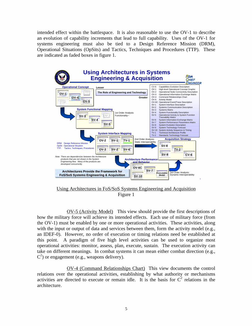
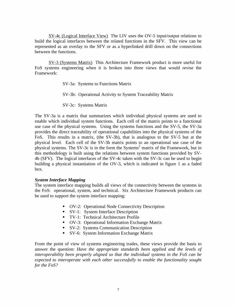
In figure 1, these groups are generally ordered (top to bottom) by the level of complexityanticipated for their use. How architectures provide the framework for FoS systemsengineering and acquisition is the subject of the remainder of this section.
The first four of the five groups of products can be generally associated with the foursteps of classical systems engineering:
§ Requirements Analysis§ Functional Analysis§ Synthesis§ Design Verification
While FoS systems engineering must follow the principles of classical systemsengineering, the complexity of the FoS and the preponderance of legacy systems in theFoS will limit in practice the system engineer’s ability to apply these principles.Requirements analysis and the functional design of the FoS to achieve specificcapabilities can be a manageable task. These become stable views of the FoS that aremuch simpler to understand than the underlying and constantly changing physicalarchitecture. Synthesis then becomes a mapping of the legacy systems in the FoS into thefunctional view of the architecture and a determination of how to use the remaining tradespace for new systems and system improvements. Design verification for the FoS isreduced in complexity by focusing on threads of systems that provide the supportingfunctionality for specific mission capabilities.
Operational ConceptThe operational concept should be a high level abstraction of the problem to be solvedand the proposed approach to solve the problem. It can also include boundary conditionsand invariants (i.e., things not in the trade space of the solution). Three ArchitectureFramework products can be used to support description of the operational concept:
§ OV-1: High Level Operational Concept Graphic§ OV-5: Activity Model§ OV-4: Command Relationships Chart
These products lay the foundation for systems development and facilitate communicationby providing context, orientation, and focus. They also serve as the entry point forrequirements flow down into the architecture.
OV-1 (High Level Operational Concept Graphic) This view shouldprovide a high level description of what the military force is and its intended effects onthe defined threat. It should also establish the boundaries of the battlespace and the usesof the military force to achieve effects. For the purpose of this initial work, we defined amission capability as the possession of the means to use military force to achieve an
5
intended effect within the battlespace. It is also reasonable to use the OV-1 to describean evolution of capability increments that lead to full capability. Uses of the OV-1 forsystems engineering must also be tied to a Design Reference Mission (DRM),Operational Situations (OpSits) and Tactics, Techniques and Procedures (TTP). Theseare indicated as faded boxes in figure 1.
Using Architectures in FoS/SoS Systems Engineering and AcquisitionFigure 1
OV-5 (Activity Model) This view should provide the first descriptions ofhow the military force will achieve its intended effects. Each use of military force (fromthe OV-1) must be enabled by one or more operational activities. These activities, alongwith the input or output of data and services between them, form the activity model (e.g.,an IDEF-0). However, no order of execution or timing relations need be established atthis point. A paradigm of five high level activities can be used to organize mostoperational activities: monitor, assess, plan, execute, sustain. The execution activity cantake on different meanings. In combat systems it can mean either combat direction (e.g.,C2) or engagement (e.g., weapons delivery).
OV-4 (Command Relationships Chart) This view documents the controlrelations over the operational activities, establishing by what authority or mechanismsactivities are directed to execute or remain idle. It is the basis for C2 relations in thearchitecture.
1
Using Architectures in SystemsEngineering & Acquisition
Operational Concept
System Functional Mapping
System Interface Mapping
OV-1OV-4
OV-5
SV-3SV-4
SV-5
OV-2
OV-3
SV-1 TV-1
SV-2 SV-6
Architecture Performanceand Behavior
OV-6CSV-7
ExecutableModel
CV-6CV-6 Capabilities Evolution DescriptionCapabilities Evolution DescriptionOV-1OV-1 High-level Operational Concept GraphicHigh-level Operational Concept GraphicOV-2OV-2 Operational Node Connectivity DescriptionOperational Node Connectivity DescriptionOV-3OV-3 Operational Information Exchange MatrixOperational Information Exchange MatrixOV-4OV-4 Command Relationships ChartCommand Relationships ChartOV-5OV-5 Activity ModelActivity ModelOV-6COV-6C Operational Event/Trace DescriptionOperational Event/Trace DescriptionSV-1SV-1 System Interface DescriptionSystem Interface DescriptionSV-2SV-2 Systems Communication DescriptionSystems Communication DescriptionSV-3SV-3 Systems MatrixSystems MatrixSV-4SV-4 System Functionality DescriptionSystem Functionality DescriptionSV-5SV-5 Operational Activity to System FunctionOperational Activity to System Function
Traceability MatrixTraceability MatrixSV-6SV-6 System Information Exchange MatrixSystem Information Exchange MatrixSV-7SV-7 System Performance Parameters MatrixSystem Performance Parameters MatrixSV-8SV-8 System Evolution DescriptionSystem Evolution DescriptionSV-9SV-9 System Technology ForecastSystem Technology ForecastSV-10SV-10 System Activity Sequence & TimingSystem Activity Sequence & TimingTV-1TV-1 Technical Architecture ProfileTechnical Architecture ProfileTV-2 TV-2 Standards Technology ForecastStandards Technology Forecast
The Role of Engineering and TechnologyThe Role of Engineering and Technology
Lesser
Greater
1st Order Analysis:Functionality--
2nd Order Analysis:Static Interoperability
3rd Order Analysis:Dynamic Interoperability
OV-3
Note: There are dependencies between the Architectureproducts that are not shown in the SystemEngineering flow. Many of the products aredeveloped concurrently.
Architectures Provide the Framework forFoS/SoS Systems Engineering & Acquisition
Architectures Provide the Framework forArchitectures Provide the Framework forFoSFoS//SoSSoS Systems Engineering & Acquisition Systems Engineering & Acquisition
SV-8TV-2
CV-6
Acquisition Strategy
SV-9
SV-10
DRMOpSits
TTP
DRM: Design Reference MissionOpSit: Operational SituationTTP: Tactics, Techniques, Procedures
6
System Functional MappingDue to the complexity of the FoSs of interest, simply bookkeeping the data describing thesystems, their relationships, and evolution is an overwhelming task. The functional viewof the solution provides a stable model which is easier to manage and against which theFOS can be mapped. Three Architecture Framework products support the systemfunctional mapping:
§ SV-4: System Functionality Description§ SV-5: Operational Activity to System Function Traceability Matrix§ SV-3: Systems Matrix
Together, these products provide the linkage and traceability of capabilities andrequirements flowdown between the operational and the physical views. The functionalview is also the first level of the architecture that is appropriate for systems assessments.The products provide the basis to answer the question: Does the FoS system architectureprovide the functionality to support the desired mission capabilities?
Assessments using this functional group of products provide the basis for a first orderanalysis of combinations of systems proposed to comprise the FoS. In the systemsengineering process, our attention will be on an FoS that is intended to solve theproblems laid out in the OV-1. For example: an analysis of gaps and duplications reducethe size of the system trade space. The result of the first order architecture analysis is thestarting point for systems engineering analysis.
SV-4 (System Functionality Description. This Architecture Framework product ismore useful for FoS system engineering when it is broken into three views that wouldrevise the Framework:
SV-4a: List of Systems Functions
SV-4b: System Functional View (SFV)
SV-4c: Logical Interface View (LIV)
The SV-4a is the list of system functions that will be used to enable or execute theoperational activities.
SV-5 (Operational Activity to System Function Traceability Matrix) This is amatrix that summarizes which individual system functions are used to enable or executewhich individual operational activities. Each cell in the matrix points to a use case of thesystem functions. Using the system functions, the SV-5 provides the traceability ofoperational capabilities into the FoS.
SV-4b (System Functional View) The SFV is derived from the OV-5 using theSV-5. It is the functional analog of the activities model and shows the relationships anddependencies amongst the system functions.
7
SV-4c (Logical Interface View) The LIV uses the OV-5 input/output relations tobuild the logical interfaces between the related functions in the SFV. This view can berepresented as an overlay to the SFV or as a hyperlinked drill down on the connectionsbetween the functions.
SV-3 (Systems Matrix) This Architecture Framework product is more useful forFoS systems engineering when it is broken into three views that would revise theFramework:
SV-3a: Systems to Functions Matrix
SV-3b: Operational Activity to System Traceability Matrix
SV-3c: Systems Matrix
The SV-3a is a matrix that summarizes which individual physical systems are used toenable which individual system functions. Each cell of the matrix points to a functionaluse case of the physical systems. Using the systems functions and the SV-5, the SV-3aprovides the direct traceability of operational capabilities into the physical systems of theFoS. This results in a matrix, (the SV-3b), that is analogous to the SV-5 but at thephysical level. Each cell of the SV-3b matrix points to an operational use case of thephysical systems. The SV-3c is in the form the Systems2 matrix of the Framework, but inthis methodology is built using the relations between system functions provided by SV-4b (SFV). The logical interfaces of the SV-4c taken with the SV-3c can be used to beginbuilding a physical instantiation of the OV-3, which is indicated in figure 1 as a fadedbox.
System Interface MappingThe system interface mapping builds all views of the connectivity between the systems inthe FoS: operational, system, and technical. Six Architecture Framework products canbe used to support the system interface mapping:
§ OV-2: Operational Node Connectivity Description§ SV-1: System Interface Description§ TV-1: Technical Architecture Profile§ OV-3: Operational Information Exchange Matrix§ SV-2: Systems Communication Description§ SV-6: System Information Exchange Matrix
From the point of view of systems engineering trades, these views provide the basis toanswer the question: Have the appropriate standards been applied and the levels ofinteroperability been properly aligned so that the individual systems in the FoS can beexpected to interoperate with each other successfully to enable the functionality soughtfor the FoS?

8
OV-2 (Operational Node Connectivity Description) The operational nodes in thisview are meaningful groupings of the activities in the OV-5 (Operational ActivityModel). These nodes are associated with physical or organizational nodes in other viewsof the architecture. They can be thought of as task-oriented cells where work isaccomplished. Because the activities of the OV-5 carry input and output relations, thenodes of the OV-2 inherit these relations, which are usually referred to as need lines.From a systems engineering point of view, the nodes in the OV-2 should be created toestablish natural lines of communication between physical locations. When thearchitecture is physically instantiated, communication occurs between operational nodes,vice between activities. However, need lines are not the communications paths. (Thecommunications paths are described in the SV-2).
SV-1 (System Interface Description) This view links the operational and systemviews of the architecture. The SV-3b (Operational Activity to System TraceabilityMatrix) provides the linkage. At the highest level, the SV-1 organizes the systems alongthe paradigm of monitor, assess, plan, execute, sustain (possibly with the C2 aspect ofexecution, i.e. combat direction, being separated from the engagement aspect ofexecution, e.g. weapons delivery). This representation relates to the OV-1 and is usefulfor high level planning. At the systems engineering level, the SV-1 is a mapping ofsystems to the OV-2 using the SV-3b. The associated operational and system need linesare in concordance because of their common derivation through the SV-5.
TV-1 (Technical Architecture Profile) The Architecture Framework representsthe technical component of the architecture as the set of rules that govern systemimplementation and operation. In this sense, the TV-1 should go beyond interfacestandards and protocols. In practice, the TV-1 is frequently seen as only the list ofstandards and protocols associated with the transport layer of interfacing andcommunications between systems. However, in the Framework 2.0 the notional exampleof the TV-1 addresses service areas, services, and standards that go beyond interfaces.Therefore, it may be appropriate to decompose the TV-1 into interface standards thatalign to an overarching accepted standard like OSI and into other standards related toservices and physical systems.
OV-3 (Operational Information Exchange Matrix) This Architecture Frameworkproduct can be adapted to our FoS system engineering process by deriving it from theoperational and system architecture products already developed. The ArchitectureFramework defines the Information Exchange Requirements (IERs) of the OV-3 view asthe relationship across the three basic entities of the operational view of the architecture(activities, operational nodes, and information flow) as a focus on the specific aspects ofinformation flow, namely who exchanges what information with whom, why theinformation is necessary, and in what manner. The OV-3 was intended to emphasize thelogical and operational characteristics of the information. However, the fundamentaloperational information exchanges are really identified at the activity level in the OV-5via the input and output relations. With our adaptation of the OV-2 as meaningfulgroupings of activities (cells where work is done) to establish communication need lines,the OV-2 becomes the more natural starting point for building the OV-3. If the non-
9
physical standards and protocols from the TV-1 are applied to these need lines, then asystematic and well organized operational view of information exchange is accomplishedand a foundation for the System Information Exchange Matrix is established.
SV-2 (Systems Communication Description) This view represents the specificcommunications systems pathways or networks and the details of their configurationsthrough which the physical nodes and systems interface. This product focuses on thephysical aspect of the information need lines represented in the OV-2 (Operational NodeConnectivity Description). It describes all pertinent communications aspects of the FoS,showing the details of need lines between the systems identified by the SV-1 (SystemInterface Description).
SV-6 (System Information Exchange Matrix) This Architecture Frameworkproduct is made more useful for FoS system engineering by expanding it into a broaderview that would revise the Framework. This expanded SV-6 would retain the attributesof the existing Framework product, which is defined as the information exchanges withina node, and from those systems to systems at other nodes. It is easily derived from theOV-3, TV-1, SV-3b and the SV-3c. This makes the SV-6 the system analog to the OV-3.The stronger SV-6 product can be derived because the matrices of the precedingarchitecture products can be used to create end-to-end views of system information andservice exchanges. Each communication and service between two systems can trace thecapabilities, activities, functionality, logical and technical interfaces of the architecture.
Architecture Performance and BehaviorThe system functional mapping and the system interface mapping provide key insightsinto the functionality and connectivity of the architecture with traceability to operationalcapability. As such, these uses of Framework Architecture products provide an earlyvalidation of the architecture and serve to answer the question: What can the architectureenable the FoS to actually do? However, the architecture is not (abstractly) validateduntil it can be executed as a flow of events, which is accomplished through the productsof performance and behavior. The group of architecture products proposed for the usecase of performance and behavior can serve to answer the questions: how well does thearchitecture perform (to deliver mission capabilities) and does it behave in waysacceptable to the users? Three Architecture Framework products support this use caseand one new product must be added:
§ OV-6c: Operational Event/Trace Description§ SV-10: System Activity Sequence & Timing Description§ SV-7: System Performance Parameters Matrix§ Executable Model (new product)
These products are necessary to support system selection decisions, which reside in thedomain of FoS systems engineering trade studies (i.e., performance and capabilities vs.cost and risk). However, these products are the most labor intensive of the five groups(use cases) to generate.
10
OV-6c (Operational Event/Trace Description) This view, which is sometimescalled a sequence diagram, is the most basic product which addresses the executability(or dynamic validity) of the operational view of the architecture. It enables thetraceability of actions in a scenario or critical sequence of events. The OV-6c organizesthe OV-5 activities around the OV-2, using the OV-4 for control (or triggering) ofarchitecture responses to scenario events. It introduces timing and sequencing into theactivity model (OV-5). Insights into dynamic validity, throughput, and node loading aregained. However, it does not address architecture performance. The performance of thearchitecture is determined by the performance of the systems and personnel that enable orexecute the operational activities.
SV-10 (System Activity Sequence & Timing Diagram) This view should beinherited from the OV-6 using the mapping of the SV-5 and other SV-3,4 products. TheArchitecture Framework calls out three systems models that are needed to accomplish thecomplete description:
§ SV-10a: Systems Rules Model§ SV-10b: Systems State Transition Description§ SV-10c: Systems Event/Trace Description
There is another view that has proven very useful in architecture assessments. Thisproposed view would be a fourth product that logically should proceed from the threestandard SV-10 Framework Products and is what is labeled an SV-10d.
SV-10d: (Systems to Operational Sequence Mapping) This view is a simplemapping of the SV-3b to the OV-6c. The result is an OV-6c with physical systemsassociated with the activity flow of the OV-6c. Military operators find this very useful.Derivation of this view through the SV-3b adds engineering discipline to the associationof physical systems and operational activities. Still though, architecture performance isnot observable until the performance metrics of the individual systems are determined,which is the purpose of the SV-7.
SV-7 (System Performance Parameters Matrix) This view builds on the SystemElement Interface Description (SV-1) to depict the current performance characteristics ofeach system, and the expected or required performance characteristics at specified timesin the future. The expected characteristics relate to the System Evolution Description(SV-8), whereas the performance requirements for physical systems are traceable onlywhen an allocated baseline has been established (i.e., functions and requirements havebeen allocated to physical systems). Building the allocated baseline requires thecollaboration of multiple stakeholders and is in the domain of FoS systems engineeringtrades that occur during synthesis.
Executable Model Execution of the architecture is required for both validationand analysis. A number of popular tools are available. RDA CHENG currently has beenusing a popular tool developed for structured analysis. However, future work will movetowards object orientation using the Universal Modeling Language (UML). This will
11
allow for better re-use of the architecture products and provide better control of attributesthrough the inheritance properties of UML. The organization, description, and uses ofthe Architecture Framework products in this paper have been written with extensibility toUML in mind, while preserving the structured analysis attributes of classical systemsengineering.
Acquisition StrategyA capabilities based acquisition strategy aligns the evolution of systems, technologies,and standards into an acquisition strategy to support the evolving capabilities needed forthe FoS. Three Architecture Framework products, and a new proposed product, areneeded to support the description of the acquisition strategy:
§ SV-9: System Technology Forecast§ TV-2: Standards Technology Forecast§ SV-8: System Evolution Description§ CV-6: Capability Evolution Description
Together, these products provide a description of the evolution and acquisition of thesystem improvements to the FoS that is traceable to mission capabilities.
SV-9 (System Technology Forecast) A system Technology Forecast is a detaileddescription of emerging technologies and specific hardware and software products. Itcontains predictions about the availability of emerging capabilities and about industrytrends in specific timeframes (e.g., 6-month, 12-month, 18-month intervals), andconfidence factors for the predictions. The forecast includes potential technologyimpacts on current architectures, and thus influences the development of transition andobjective architectures. The forecast should be tailored to focus on technology areas thatare related to the purpose for which a given architecture is being build, and shouldidentify issues that will affect the architecture.
TV-2 (Standards Technology Forecast) A Standards Technology Forecast is adetailed description of emerging technology standards relevant to the systems andbusiness processes covered by the architecture. It contains predictions about theavailability of emerging standards and the likely obsolescence of existing standards inspecific timeframes (e.g., 6-month, 12-month, 18-month intervals), and confidencefactors for the predictions. It also contains matching predictions for market acceptance ofeach standard and an overall risk assessment associated with using the standard. Theforecast includes potential standards impacts on current architectures, and thus influencesthe development of transition and objective architectures. The forecast should be tailoredto focus on technology areas that are related to the purpose for which a given architecturedescription is being built, and should identify issues that will affect the architecture.
SV-8 System Evolution Description) The System Evolution Descriptiondescribes plans for “modernizing” a system of suite of systems over time. Such effortstypically involve the characteristics of evolution (spreading in scope while increasingfunctionality and flexibility), or migration (incrementally creating a more streamlined,efficient, smaller and cheaper suite), and will often combine the two thrusts. This
12
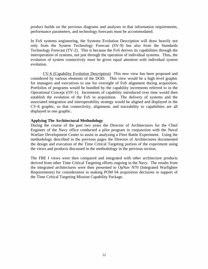
product builds on the previous diagrams and analyses in that information requirements,performance parameters, and technology forecasts must be accommodated.
In FoS systems engineering, the Systems Evolution Description will draw heavily notonly from the System Technology Forecast (SV-9) but also from the StandardsTechnology Forecast (TV-2). This is because the FoS derives its capabilities through theinteroperation of systems, not just through the operation of individual systems. Thus, theevolution of system connectivity must be given equal attention with individual systemevolution.
CV-6 (Capability Evolution Description) This new view has been proposed andconsidered by various elements of the DOD. This view would be a high level graphicfor managers and executives to use for oversight of FoS alignment during acquisition.Portfolios of programs would be bundled by the capability increments referred to in theOperational Concept (OV-1). Increments of capability introduced over time would thenestablish the evolution of the FoS in acquisition. The delivery of systems and theassociated integration and interoperability strategy would be aligned and displayed in theCV-6 graphic, so that connectivity, alignment, and traceability to capabilities are alldisplayed in one graphic.
Applying The Architectural MethodologyDuring the course of the past two years the Director of Architectures for the ChiefEngineer of the Navy office conducted a pilot program in conjunction with the NavalWarfare Development Center to assist in analyzing a Fleet Battle Experiment. Using themethodology described in the previous pages the Director of Architectures documentedthe design and execution of the Time Critical Targeting portion of the experiment usingthe views and products discussed in the methodology in the previous section.
The FBE I views were then compared and integrated with other architecture productsderived from other Time Critical Targeting efforts ongoing in the Navy. The results fromthe integrated architectures were then presented to OpNav N70 (Integrated WarfighterRequirements) for consideration in making POM 04 acquisition decisions in support ofthe Time Critical Targeting Mission Capability Package.
13
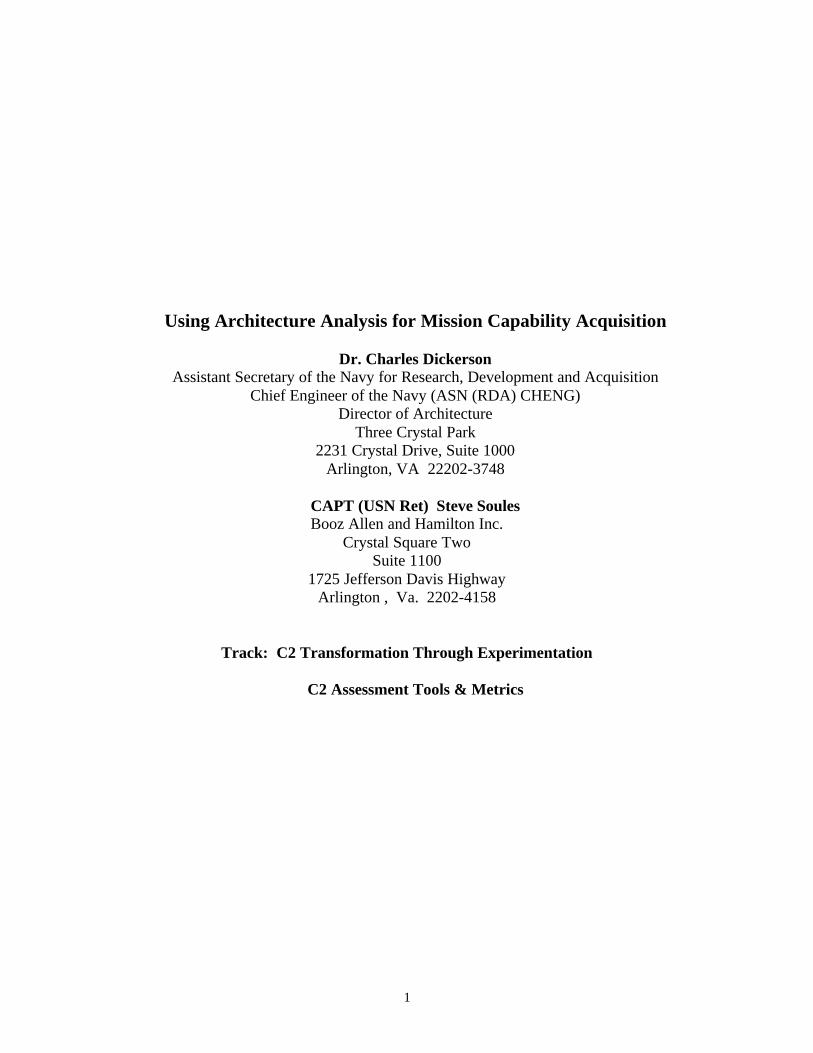
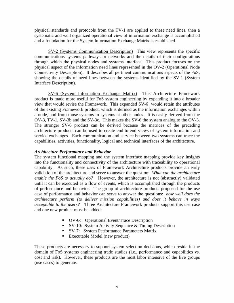
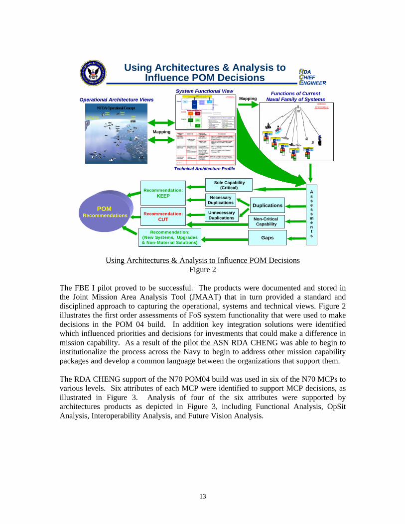
Using Architectures & Analysis to Influence POM DecisionsFigure 2
The FBE I pilot proved to be successful. The products were documented and stored inthe Joint Mission Area Analysis Tool (JMAAT) that in turn provided a standard anddisciplined approach to capturing the operational, systems and technical views. Figure 2illustrates the first order assessments of FoS system functionality that were used to makedecisions in the POM 04 build. In addition key integration solutions were identifiedwhich influenced priorities and decisions for investments that could make a difference inmission capability. As a result of the pilot the ASN RDA CHENG was able to begin toinstitutionalize the process across the Navy to begin to address other mission capabilitypackages and develop a common language between the organizations that support them.
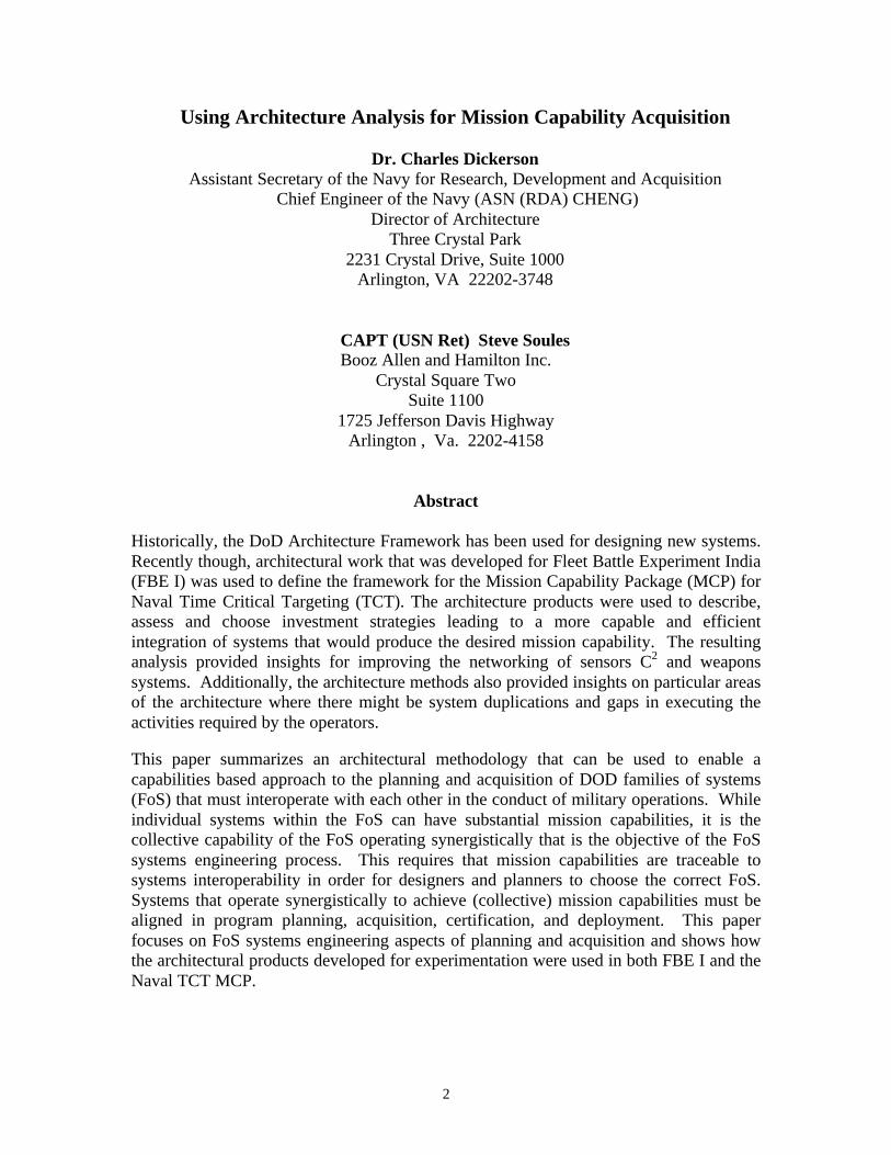
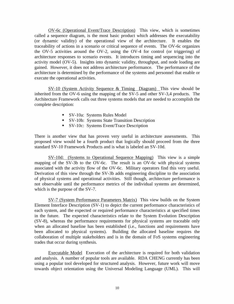
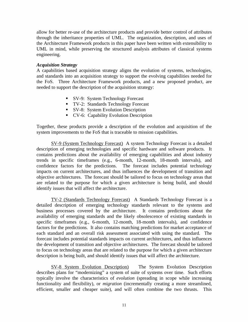
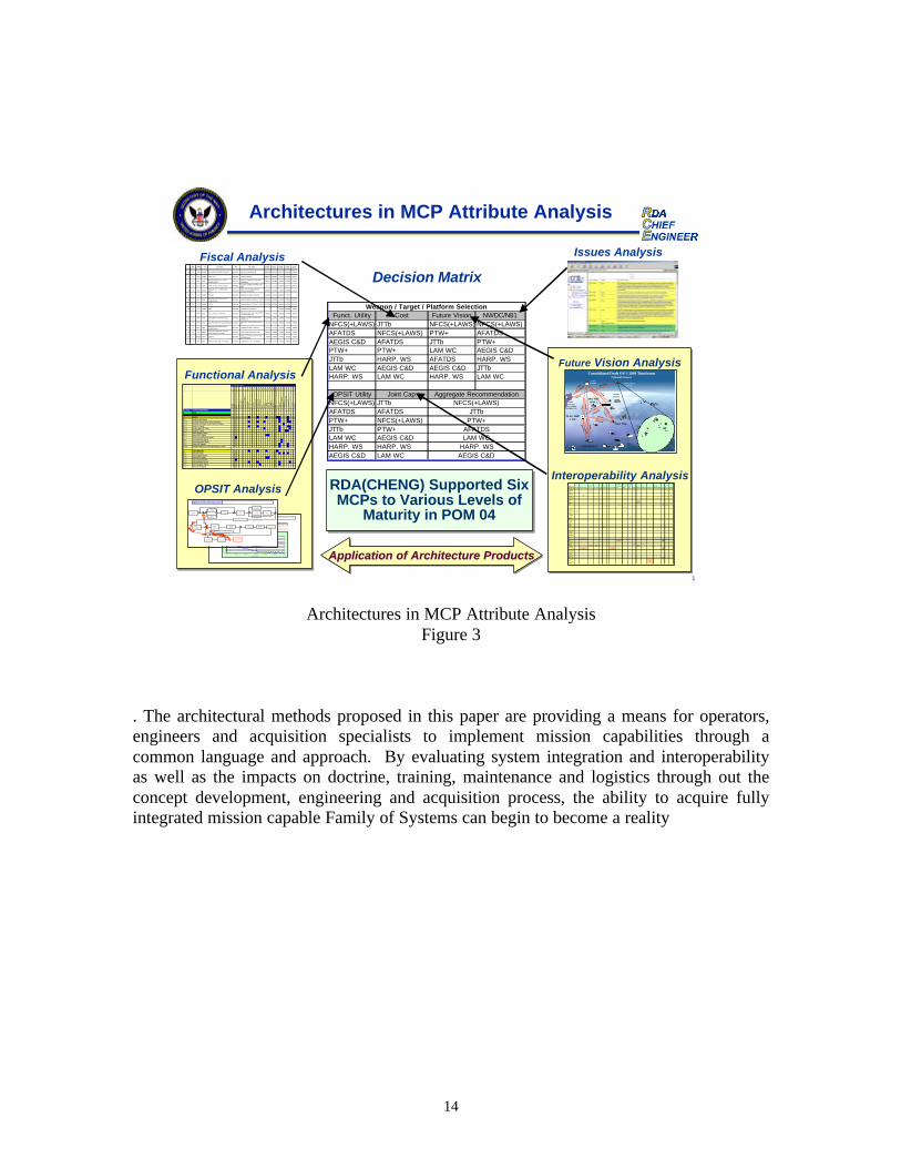
The RDA CHENG support of the N70 POM04 build was used in six of the N70 MCPs tovarious levels. Six attributes of each MCP were identified to support MCP decisions, asillustrated in Figure 3. Analysis of four of the six attributes were supported byarchitectures products as depicted in Figure 3, including Functional Analysis, OpSitAnalysis, Interoperability Analysis, and Future Vision Analysis.
Recommendation:KEEP
DuplicationsUnnecessaryDuplications
NecessaryDuplications
Recommendation:(New Systems, Upgrades& Non-Material Solutions)
Mapping
CNTWGS-84 Navigation & UTC (USNO) Time Information
CGP
SL
CM
SRCRD
EV
CEO
EW
CES
Local Data
Detect
Decide
Engage
WORK IN PROGRESSFOR ILLUSTRATION ONLY
Commander’s Intent
Common Air Picture
• Sense Locally (SLSL)• Sense Remotely (SRSR)• Communicate Remote Data
(CRDCRD)• Create Common Ground
Picture (CGPCGP)• Control and Commit
Weapons (CMCM )
• Evaluate ( EVEV)• Communicate Engagement
Order (CEOCEO)• Employ Weapons (EWEW)• Communicate Engagement
Status (CESCES)• Supply Common Nav &
Time (CNTCNT)
Enabling Functions for Mission CapabilityEnabling Functions for Mission Capability
Operational Architecture ViewsOperational Architecture Views
System Functional ViewSystem Functional View
SL
CEOCES
EW
CMEV
EW
SR
SR
WORK IN PROGRESSFOR ILLUSTRATION ONLY
NOTE: Not all FBE-I platforms and systems here have been represented
Camp Pendleton/USA TESUS ARMY
SIM CELL
USS CORONADO
USS BONHOMMERICHARD
USS JOHN C.STENNIS
Commercial Satellite
KB(X)
NRLSATCOM
1 MB
1 M
B
1 MB
1 MB
Telestar 5
1 MB
1 MB
1 MB
CG DDGCRD
CEOCES
CMEV
CNT
CGP
SRCRD
CEOCES
CMEV
CNT
CGP
SRCRD
CEOCES
CMEV
CNT
CGP
CGPCRD
CEOCES
EW
CMEV
CNT SRCGP
CRDCNT
SL
CEOCES
EW
CMEV
EW
SR
SR
WORK IN PROGRESS
NOTE: Not all FBE-I platforms and systems here have been represented
SatelliteKB(X)
5
DDGCRD
CEOCES
CMEV
CNT
CGP
SRCRD
CEOCES
CMEV
CNT
CGP
SRCRD
CEOCES
CMEV
CNT
CGP
CGPCRD
CEOCES
EW
CMEV
CNT SRCGP
CRDCNT
Functions of CurrentNaval Family of SystemsNaval Family of Systems
Technical Architecture ProfileTechnical Architecture Profile
POM Recommendations
Gaps
National Sensors
NTOA Operational ConceptCommsSatellites
ARG
SAG
CVBG
Theater Sensors
FO
National/Theater/ServiceIntel/Targeting Centers
TacticalSensors
Mapping
Assessments
Sole Capability(Critical)
Recommendation:CUT Non-Critical
Capability
Using Architectures & Analysis toInfluence POM Decisions
14
Architectures in MCP Attribute AnalysisFigure 3
. The architectural methods proposed in this paper are providing a means for operators,engineers and acquisition specialists to implement mission capabilities through acommon language and approach. By evaluating system integration and interoperabilityas well as the impacts on doctrine, training, maintenance and logistics through out theconcept development, engineering and acquisition process, the ability to acquire fullyintegrated mission capable Family of Systems can begin to become a reality
1
Architectures in MCP Attribute Analysis
Funct. Utility Cost Future Vision NWDC/N81NFCS(+LAWS) JTTb NFCS(+LAWS) NFCS(+LAWS)AFATDS NFCS(+LAWS) PTW+ AFATDSAEGIS C&D AFATDS JTTb PTW+PTW+ PTW+ LAM WC AEGIS C&DJTTb HARP. WS AFATDS HARP. WSLAM WC AEGIS C&D AEGIS C&D JTTbHARP. WS LAM WC HARP. WS LAM WC
OPSIT Utility Joint Cap.NFCS(+LAWS) JTTbAFATDS AFATDSPTW+ NFCS(+LAWS)JTTb PTW+LAM WC AEGIS C&DHARP. WS HARP. WSAEGIS C&D LAM WC AEGIS C&D
HARP. WS
JTTb
Aggregate RecommendationNFCS(+LAWS)
LAM WC
PTW+
Weapon / Target / Platform Selection
AFATDS
case6.dat NOTIONAL Sensor and Weapon Performance Data
T B M T E L s ( s t a t i o n a r y = 2 4 0 0 s e c ) U 2 P r o b a b i l i t y o f a h i tT T L A M
G r a p h
Op Sit Sensor Weapon Statistics Option
D A A T R e s u l t
00 . 1
0 . 20 . 3
0 . 4
0 . 50 . 6
0 . 70 . 8
0 . 9
1
0 6 0 0 1 , 2 0 0 1 , 8 0 0 2 , 4 0 0 3 , 0 0 0 3 , 6 0 0
T i m e ( s e c )
T h r e a d 1
T B M T e l T T L A M T h r e a d 1 Assumpt ions : TTLAM was prepos i t ioned in lo i te r o rb i t 50 nm f rom s u s p e c t e d t a r g e t a r e a ;No th rea t i n a r ea .
A s s e s s
I S R C u e
R e c o n c i l e
T a r g e t
P r i o r i t i e s
T a s k
S e n s o r
D e t e r m i n e
S e n s o r
A v a i l a b i l i t y
D e t e c t
T a r g e t
G e o l o c a t e
T a r g e t
T r a c k u n t i l
S t o p p e d
I D T a r g e t
D e t e r m i n e
E n v i r o n m e n t
A s s e s s
E n g a g e m e n t
C a p a b i l i t y
U p d a t e
M i s s i o n
P l a n s
E x e c u t e
F o r c e O r d e r
S u p p o r t
W e a p o n
F l y o u t
D D D T a r g e t
A s s e s s
B D I / B H I
C o l l e c t
B D I / B H I
R e m o v e
f r o m T a r g e t
L i s t
E E
I
E
E
E
N o m i n a t e T a r g e tU p d a t e T a r g e t L i s t
A s s i g n
w e a p o n /
T a r g e t /
P l a t f o r m
S e l e c t i o n
P e r f o r m T C T D e c o n f l i c t i o n R e e n g a g e
R e t a r g e t
1 . 1
2 . 1
2 . 2
2 . 3 3 . 1
3 . 2
3 . 3
3 . 4
3 . 5
4 . 1
4 . 24 . 3
4 . 4
4 . 5
5 . 1 5 . 2 5 . 3
6 . 1 6 . 2 6 . 3
T B M T E LT T L A M
N F C S
T P S
G C C S - M
N F C S
P T WU A V C G S
G C C S - M
G C C S - M
C G S
T E S S / N I T E S 2 0 0 0
D C G S
U 2 P T W N F C S
T B M T e l T T L A M T h r e a d 1 A s s u m p t i o n s : T T L A M w a s p r e p o s i t i o n e d i n l o i t e r o r b i t 5 0 n m f r o m s u s p e c t e d t a r g e t a r e a ;
N o t h r e a t i n a r e a .
TCS System Name
1 2 3 4 5 6 7 8 9 10 11 12 13 14 15 16 17 18 19 20 21 22 23 24 25 26 27 28 29 30
AC
DS
AD
NS
AD
SA
egis
Aeg
is C
&D
Aeg
is F
CS
Aeg
is S
IGP
RO
AF
AT
DS
AIE
WS
ALA
MA
MC
&D
AN
S/M
OU
SA
N/B
LQ-1
0A
N/S
MQ
-11
AP
SA
PY
-6A
TA
RS
AT
FLI
RB
GP
HE
SC
DL-
NC
GS
CID
CO
BLU
CO
BLU
/SS
EE
CO
BR
AC
OB
RA
/EP
LRS
Com
bat D
FC
omm
on E
CM
CT
AP
SC
WS
P
Sys Funct # System Function Name1 Sense
1.1 Search 1.1.1 Create Search strategy1.1.1.1 Generate Organic Sensor Search Instructions1.1.1.2 Generate Non-Organic Sensor Search Instructions1.1.2 Search RF Signals1.1.2.1 Conduct Active RF Search1.1.2.2 Manual RF Search1.1.3 Search Imagery Signals1.1.4 Search IR/EO Signals1.1.5 Search Acoustic/Seismic Signals1.1.6 Search Radar/IFF Signals1.1.7 Search Navigation Signals1.1.8 Search EM Spectrum1.1.8.1 Manually Programmed Automated Frequency Search
1.2 Signal Detection1.2.1 Detect RF signals1.2.2 Detect Imagery Signals1.2.3 Detect IR/EO Signals1.2.4 Detect Acoustic/Seismic1.2.5 Detect Radar/IFF Signals1.2.6 Detect Navigation Signals1.2.7 Detect Visual Signals
Decision Matrix
OPSIT Analysis
Functional Analysis
RS APPN CLI CLI TITLE PE PE TITLE $2002 $2003 $2004 $2005 $2006
133 78 APN 014500 F/A-18E/F (FIGHTER) HORNET 0204136N (U)F/A-18 SQUADRONS 2801039 2916841 2956563 2881205 3030106
412 77 SCN 201300 NEW SSN 0204281N (U)SUBMARINES 2093202 2002534 1977324 2389204 2685572
111 78 MPN 1B1BMISSION AND OTHER SHIP
OPERATIONS0204112N
(U)MULTI-PURPOSE AIRCRAFT
CARRIERS1786331 1907086 1937881 1997591 2075906
1203 78 RDTEN D2261 JOINT STRIKE FIGHTER EMD 0604800N(U)JOINT STRIKE FIGHTER (JSF) -
EMD767259 1737130 1941444 2108915 2098781
748 78 APN 016400MEDIUM LIFT ALTERNATIVE
(MLA)0206121M
(U)CH-46/V-22 SQUADRONS
(MARINE AIR WING)1308309 1579606 1520905 1469486 1704462
260 76 SCN 212200 DDG-51 0204222N (U)DESTROYERS - MISSILE 2146036 2197759 2202996 478517 0
485 75 MPN 1B1BMISSION AND OTHER SHIP
OPERATIONS0204411N (U)AMPHIBIOUS ASSAULT SHIPS 1012159 1079492 1134728 1176695 1201762
493 75 SCN 303600 LPD17 0204411N (U)AMPHIBIOUS ASSAULT SHIPS 1091330 1675993 1688984 1013764 1011431
297 76 SCN 211900 DD21 0204228N (U)SURFACE SUPPORT 0 0 293479 1826856 128361
7 77 OMN 1D2D FLEET BALLISTIC MISSILE 0101221N (U)STRATEGIC SUB & WEAPONS SYSTEM SUPPORT
808451 795046 824764 847084 890063
114 78 OMN 1B4B SHIP DEPOT MAINTENANCE 0204112N (U)MULTI-PURPOSE AIRCRAFT CARRIERS
813503 1131042 639823 734499 658435
1259 78 OMN 1A5A AIRCRAFT DEPOT MAINTENANCE 0702207N (U)DEPOT MAINTENANCE (NON-IF)
827760 753626 786960 753519 780298
257 76 MPN 1B1BMISSION AND OTHER SHIP
OPERATIONS0204222N (U)DESTROYERS - MISSILE 537572 617767 691045 768658 839980
178 78 APN 060590AIRCRAFT REPLEN SPARES
(AVIATION OUTFITTING)0204161N (U)AVIATION SUPPORT CVW 693522 549665 511352 668142 648556
1167 76 RDTEN 32464 DESIGN 0604300N(U)SC-21 TOTAL SHIP SYSTEM
ENGINEERING234464 585404 759471 875561 692934
1441 76 MPN 3B1K SPECIALIZED SKILL TRAINING 0804731N (U)GENERAL SKILL TRAINING 491105 517311 533253 545418 558499
Fiscal Analysis
System Element ACDS AEGIS C&D
AEGIS WCS ATWCS C2P
E-2C MCU FTI GCCS-AF
GCCS-M/JOTS1_CV
Global Hawk MCE
Global Hawk UAV HWS JMPS
JSF computer JSIPS-N
JSOW (BASELINE) JTT JTW LASM
ACDS XAEGIS C&D
X
AEGIS WCS
X X
ATWCSC2PE-2C MCU
X
FTI X X X
GCCS-AFX
GCCS-M/JOTS1_CV
X X
Global Hawk MCE
X X
Global Hawk UAV
X
HWSJMPS XJSF computer X
JSIPS-NJSOW (BASELINE)JTT X XJTW X XLASMMIDS X XNFCS X X XPTW/PTW+_CVIC
X X X X
SLAM/SLAM-ERTAPSTBMCSTES-N X XTESS/ NITES 2000
X
Interoperability Analysis
National IntelSensors
CommSatellite
Single Ship
CVBG/JFACC
Theater Sensors
Consolidated Draft OV-1 2006 TimeframeNational Sensors
IntelProduction
Center/HigherHeadquarters
FLAG SHIPCJTF
SIGIN
T/IM
INT
/AL
ER
TS
RE
AC
HB
AC
K/R
FIs
IMAGERY/SIGNALS/ETC.
C2 DIRECTION
RE
AC
HB
AC
K/R
FIs
SIGIN
T/IMIN
T
SIGINT/IMINT/ALERTS
REACHBACK/RFIs
SIGIN
T/IM
INT
/AL
ER
TS
REACHBACK/RFIs
SIGINT/IM
INT/ALERTS
ARG/MEUJFMCC
ALERTS & CUEING
REQUESTS FOR INFO (RFIs)SMART PUSH
REQUESTS FOR INFO (RFIs)
RE
QU
EST
S FO
R IN
FO
(RF
Is)SM
AR
T P
USH
SMART PUSH
Future Vision Analysis
RDA(CHENG) Supported SixMCPs to Various Levels of
Maturity in POM 04
RDA(CHENG) Supported SixMCPs to Various Levels of
Maturity in POM 04
Issues Analysis
Application of Architecture ProductsApplication of Architecture Products