Embed Size (px)
Citation preview

Using a Garmin GPS
with paper maps for land navigation
An introduction to...

© 2005 Garmin Ltd. or its subsidiaries
Garmin International, Inc.1200 East 151st Street, Olathe, Kansas 66062, U.S.A.Tel. 913/397.8200 or 800/800.1020Fax 913/397.8282
Garmin (Europe) Ltd.Unit 5, The Quadrangle, Abbey Park Industrial Estate, Romsey, SO51 9DL, U.K.Tel. 44/1794.519944Fax 44/1794.519222
Garmin Corporation No. 68, Jangshu 2nd Rd., Shijr, Taipei County, TaiwanTel. 886/2.2642.9199Fax 886/2.2642.9099
All rights reserved. Except as expressly provided herein, no part of this guide may be reproduced, copied, transmitted, disseminated, downloaded or stored in any storage medium, for any purpose without prior written consent of Garmin Corpora-tion. Garmin Corporation hereby grants permission to download a single copy of this guide onto a hard drive or other electronic storage medium to be viewed for personal use, provided that such electronic or printed copy of this guide contains the complete text of this copyright notice and provided further that any unauthor-ized commercial distribution of this guide is strictly prohibited.
Web site address: www.Garmin.com
Garmin®, GPSMAP®, eTrex®, and MapSource® are registered trademarks of Garmin, Ltd, or its subsidiaries and may not be used without the express permission of Garmin, Ltd.
October 2005 Part Number 190-00225-00 Rev. B Printed in U.S.A

1
Introduction
Table of ContentsSection 1 - IntroductionIntroduction to GPS and Paper Maps....................................................2How does a Garmin GPS work with maps?.................................3Electronic Maps vs Paper Maps.........................................................4-5Garmin features that compliment Map Navigation..................................6-7
Section 2 - About Paper MapsMapping the Earth........................................................................8-11Longitude and Latitude.....................................................................12True & Magnetic North...............................................................................13Universal Transverse Mercator Projections (UTM Grids).........................14-16Map Datums............................................................................................17
Section 3 - NavigationUsing a Traditional Compass for Navigation..........................................18-20Using a GPS Compass ..............................................................................20Reading Maps..............................................................................21-22 Map Information ...............................................................21 Map Scales................................................................................22Locating Map Items Using Map Tools...................................................23-28 Using the Grid Overlay Tool.....................................................................24 Using the Corner Ruler..............................................................25 Using the Lat/Lon Scale......................................................................25 Using the Compass Rose................................................................26-28 How a GPS simplifies map navigation..................................................29 GPS Accuracy..............................................................................30Map Accuracy...................................................................................30
Section 4 - AppendicesAppendix A: Glossary of Mapping, Navigation, and GPS Terminology....31-33Appendix B: Index of Web sites by Subject...............................................34-35Appendix C: Garmin GPS Purchase Selection Guide......................................36Appendix D: Reproducible Map Tools...........................................................37Appendix E: Satellite Geometry...........................................................38Appendix F: Using the Altimeter Feature..........................................................39

2
Introduction
Introduction to GPS and Paper Maps
Paper maps have traditionally been the primary navigation tool for centuries. Maps are most reliable when used with a compass to determine orientation and direction. With the advent of GPS technology, you might think that maps have become obsolete. Just the opposite, they have become even more useful. This guide contains practical information for using the features contained in your Garmin GPS unit to compliment navigation with paper maps.
To help you understand the relationship between paper maps and Garmin GPS units, you will be given a brief introduction to using maps for navigation on land, and how that form of navigation is enhanced and even simplified when using a Garmin GPS.
You will learn how flat paper maps of a geospheric earth were devel-oped, what compensations were made to create accurate flat maps. You will also learn how GPS unit features have improved methods of navigation using traditional maps. The maps used for our demonstrations are United States Geological Survey System (USGS) topographic maps.
For the most part, just about everyone can understand the basic presentation of a map; however, understanding the practical applications of map reading for accurate navigation requires some instruction.
Our goal is to lead you into map navigation with some basic dis-cussions and exercises, and provide you with paths to discover more information on your own, through the use of detailed references found at various sites on the world wide web. Map reading and navigation is a skill developed by practice. Our goal is to help you understand map basics and to appreciate the value of a Garmin GPS when used for land navigation.
To take you to a more in depth look at paper map navigation, a list of recommended web sites, by subject, is contained in the Appendix at the back of this guide.

3
How does a Garmin GPS work with maps?
Before you can answer this question, you must know how maps work. Once you have a working knowledge of how maps are designed for naviga-tion, the GPS question will be, for the most part, automatically answered. Automatic is the key word to understanding the Garmin GPS unit and its relationship to map navigation.
GPS has a variety of applications on land, at sea and in the air. Basi-cally, GPS allows you to determine your location and find other locations on the earth. It helps you navigate to and from those locations. GPS can be used everywhere except where it’s impossible to receive a satellite signal such as inside buildings; in caves, parking garages, other subterranean locations; and underwater. The most common airborne applications include navigation by general aviation and commercial aircraft. At sea, a GPS is typically used for navigation by professional mariners, recreational boaters, and fishing enthusiasts.
If you are involved in an activity or sport where you need to keep track of where you are, find your way to a specified location, or know what direc-tion and how fast you’re going, you can benefit from the Global Position-ing System and a Garmin GPS unit. For this discussion, we are using the Garmin GPSMAP 60CS to demonstrate the GPS functions. Its small size, electronic compass and altimeter make it ideal for off-road travel where a paper map is being used as a reference. Although this is a full featured Garmin product, even basic Garmin models can enhance and simplify paper map navigation. To learn detailed information on specific Garmin unit operation, refer to the Owner’s Manual and Reference Guide for that product, available on the web at www.Garmin.com.
If you are a first time buyer or desire an upgrade from your current GPS unit, a comprehensive GPS applications and Garmin model selector guide is presented in the Appendix.
GPSMAP 60CS
Introduction

4
Electronic Maps and Paper Maps
In this guide, we are going to limit our discussion to Land-based appli-cations and navigation using both a Garmin GPS and a paper map. In most comparisons you would expect a discussion of the advantages of one over the other, but, in the case of paper maps and a GPS unit, there aren’t many disadvantages. In fact, a GPS is designed with features to enhance the capa-bility of paper maps and paper maps enhance the capability of a GPS. One advantage of a paper map is that without much instruction you can read and use it to perform basic navigation tasks. The same is true for a GPS. With some basic map and compass instruction you can determine your approxi-mate location on a paper map. With the press of a button you can use a GPS to determine your exact location anywhere in the world. Paper maps provide you with a “big” picture of the area around your location and depict landmarks, roads, waterways, towns, etc. in great detail.
Most Garmin GPS units contain an electronic map similar to a paper map but with these differences: there is not as much detail on the electronic map, but you can change the scale of the electronic map (zoom in or out), you can identify an item on the map and create a path to it along with navi-gation assistance to keep you on track to your destination. You can measure your rate of progress and can even store information about the destination and the route to it for future use. You can also customize the method in which the map displays its features, by controlling the size of text, removing some items to simplify the amount of items shown, etc. You can download a variety of Garmin MapSource Maps to most Garmin units.
Introduction
Paper Map Features complimented by Garmin GPS Receivers
Paper Maps GPS ReceiversMap Scale Map Scale with Zoom In/Out capabilityMagnetic North Declination Information North Reference Setting OptionsDesigned from a map projection format Location format matching capabilityDesigned to a Map Datum Map Datum matching capabilityUnits of measurement Units of measurement optionsGeographical Features Geographical Features with display options
Paper Maps using Map Tools & Compass GPS Built-In FeaturesMeasuring distance between map points Measure Distance featureProjecting a bearing to a map point Automatic bearing feature (GoTo)Plotting a position on the map Automatic plotting (Mark Waypoint)Using a compass to navigate on a bearing Auto navigation (Nav Pages) (CDI)Locating yourself on a map Marking your current locationMarking a route to a destination Creating a Route of waypointsMeasuring your progress Automaitc calculation (Trip Computer)

5
Introduction
USGS Topographic Map - Scale 1: 50,000
GPSMAP 60CS GPS“Zoomed In“
Topographic Map Display
GPSMAP 60CS GPS“Zoomed Out“
Topographic Map Display
Paper Map
GPS Electronic Map
While paper maps provide great detail and a large view of the map area, electronic maps can display only a small area in detail, they can ultimately depict the entire earth and have the added convenience of Zoom In and Zoom Out map scale selection. GPS maps do not typically display at the same scale as a paper map but can be zoomed in or out to approximate a paper map scale. The panning arrow on Garmin GPS units with built-in maps allow you to move about on the map to view details within the scope of the map coverage area. Using the panning arrow to locate any point on the map you can mark the location as a waypoint to create a destination, or mark your current location. The panning arrow also allows you to measure the distance between two points on the map.
Panning Arrow
Map Scale

6
Introduction
Matching Garmin GPS Features to a Map for Navigation
If you currently own a Garmin GPS, then you undoubtedly have browsed through the menu of features. You will have noticed a “Settings” option containing option entry windows for:
• Location Format Map Datum
• North Reference Magnetic Variation
• Direction Display
These options allow you to match your GPS unit to almost any map, which is essential if you want use your GPS in conjunction with a map for navigation.
In addition, your GPS will contain a ‘Mark Waypoint’ feature which may offer position averaging for increased accuracy, a ‘Trip Computer’ to measure and record time and distance, a Course Deviation Indicator (CDI), and finally a Map or Navigation Page that displays your current position on a map. Also included on the ‘Map’ Page is a compass direction display, a ‘Tracks’ display (a visual record of your movement) and a move-able panning arrow that you can move about on the map to highlight a map item to measure the distance to the item, learn more about it through an information page or to record it as a destination waypoint.
You can create a route to a destination on your paper map and then transfer the coordinates for each point on the route to your GPS. With this information the GPS reconstructs the route and lead you to your destina-tion providing time and distance information as you travel.
A basic understanding of how to plot coordinates for items identified on your map and to plot your position on a map is essential for combin-ing the information on a map with the navigation capabilities of a Garmin GPS.
As you read through the various explanations and exercises, you will see how the Garmin GPS features listed on the following pages can aid and simplify the navigation process.

7
Map Page with Panning Arrow: An electronic map with a Zoom In and Zoom Out feature that allows you to change the map scale at will. The scale is displayed in the lower left corner of the display. A pan-ning arrow allows you to move about on the map and to scroll the map to reveal more viewing area. Unlike a paper map with size limitations, a basemap can be panned to view a major portion of the earth.
Navigation Page: A compass with direction or bearing arrow, and in some units, a highway page with a graphic navigation path (highway). These pages are also accompanied by selectable data fields to track time, distance, speed, and heading information.
For these pages to work accurately and in accordance with informa-tion on your map, some adjustments to the GPS unit ‘Setup’ must be made to match the methods in which you are navigating with your map.
Heading Display and North Reference: Under the Heading set-tings options you will find a ‘Heading’ and a ‘North Reference’ options window. Depending on how you want to navigate you can choose a direction display of Cardinal Letters (N,S,E,W), Degrees, or Mils. Depending on how you intend to measure and project bearings on your map, you can choose a ‘North Reference’ of Auto, True North, Magnetic North, Grid North, or User North (in which you must have enough knowledge about the map you are using to set the declination to match the map). The GPS can automatically calculate the magnetic declination for your current position.
Position Format and Map Datum: The ‘Set Up’ menu will offer you a ‘Units’ page or ‘Location’ tab where you can select the posi-tion format and the map datum to match the map you are using. A position format can be selected that matches the method in which your map coordinates are measured. Choose the format that matches your map. Lat/Lon can be expressed in degrees, minutes and seconds (ddd.mm.ss.s), decimal degrees (ddd.dddd) or degrees and decimal minute (ddd.mm.mmm). If you’re using a USGS 7.5 minute topo map, choose UTM/UPS.
The Map Datum selected must match that identified on the map margin. For USGS 7.5 minute topos, use NAD 27 CONUS unless the map specifies otherwise. You can also set distance, speed, and elevation displays to match the desired units of measurement on the map.
Introduction
Here is a quick look at the Garmin GPS screen displays for features that compliment map navigation. Each displayed feature contains a brief description as well.
Map Page with Panning Arrow
Navigation Settings
Highway Page
Navigation Page with Compass
Location and Datum Formats

8
About Paper Maps
Mapping the Earth The basic method of determining your location or anything else on the earth is to use a global reference system. The system most generally accepted is a coordinated grid system comprised of hypothetical lines that encircle the earth in vertical and horizontal directions. The horizontal lines make parallel circles around the globe called Parallels of Latitude while the vertical lines divide the earth into segments that meet at each pole and are called Meridians of Longitude. Of the lines of latitude, one, the equa-tor, circles the earth exactly midway between the north and south poles. The location of each of the other parallels of latitude is determined by measuring the angular distance from the parallel and the center of the earth expressed in degrees, minutes and seconds. The lines of longitude begin with the one that runs through Greenwich, England and is designated as the Prime Meridian. The angular distances between meridians ranges from 0 degrees at the Prime Meridian to 180 degrees at the meridian located on the opposite side of the globe (International Dateline). Longitude indicates how far a location on the globe is located to the east or west of the Prime Meridian (i.e. 50o W or 60o E). Together parallels and meridians construct a grid measurement system known as a Graticule, as shown on the following page.. When describing a particular location by latitude and longitude, the latitude is always stated first in degrees, minutes, and seconds followed by the designation N for north or S for south depending on which side of the equator the location rests. The longitude is given next in degrees, minutes, and seconds, followed by E for east or W for west of the Prime Meridian. When measuring latitude and longitude on a map, first measure right (east) from vertical grid line nearest the desired map location and then up (north) from the nearest horizontal grid line to the map location. This process is commonly expressed as “easting” and “northing”.
Now because this graticule (grid system of measurement) defines a spherical (3-D) shape, it isn’t possible to create a flat paper map of the earth without some distortion. So, in response for the need to chart locations of things and yourself on the earth and create a route to others, various types of maps have been devised to fit the various needs for navigation, research, and documentation of the earth’s physical features. When you actually travel on the earth you are, in truth, traveling not a straight line from one place to another, but rather in an arc that fits the curvature of the earth, known as a Great Circle. If this arc was drawn on a two dimensional map it

9
About Paper Maps
Constructing a GraticuleMapping the Earth
Lines of Latitudeor Parallels
Equator
North Pole
South Pole
Lines of Longitudeor Meridians
Central Meridian
Prime Meridian 0o
at Greenwich, EnglandLines of latitude are measured at
angles originating at the theoretical center of the earth
Equator
A section of the surface of the earth flat-tened to create a paper map.
Central Axis of the Earth
There are 60 meridians, each 6o apart radiating from the earth’s Axis
At 180o on the opposite side of the earth, is the International Date Line

10
About Paper Maps
would not appear to be a direct route. The distortion is the result of depict-ing (the technical term is projecting) the curved surface of the earth on a flat surface. However, the most ingenious of the map makers have devised methods of projecting the earth onto a map that provides you with the best possible solution for accurate measurement of distance and thus locating a position on the earth from another position and traveling to it (accurate navigation). In addition, the smaller the section of the earth portrayed on a map the less the distortion. An example often used is to cut the peel of an orange into sections from top to bottom. Cut a wide section and try to lay it on a flat surface without it bulging and stretching. However cut a narrower section and then cut a small section from the middle of that and place it on a flat surface. The distortion is not as noticeable and that true for maps of very small portions of the earth, like the maps we use to navigate in a national forest.
Map Projections The type of map you are most likely to use is the Mercator Cylindri-cal Projection. It is most useful for navigation because a straight line on the map corresponds to a compass heading. The example of the map of the earth shows both parallels and meridians as straight lines that cross at right angles. Meridians are equally spaced, but parallels are not because the Mercator projection straightens the lines of longitude and increases the space between the lines of latitude equal to the space of longitudinal widening. Maps made this way are most accurate within 15 degrees of the Equator and because distortion is so severe at the northern and southern portions of the map the projection stops at the 84th parallel. This distor-tion is so great that land masses at these limits appear to be much larger than they really are in relation to land masses near the equator. Above and below the 84th parallels. The polar regions are depicted using a Conical Projection which we won’t discuss here as it doesn’t have much practical use for most of us.
Because the lines of longitude move closer together as they near and merge at the poles, or and decreases proportionally as you move toward the poles where the meridians intersect, and there are zero degrees of longi-tude. Regardless of these differences, you can easily determine the distance between to locations on the earth with the proper measuring techniques.
Two other variations on the Mercator Projection are the Universal Transverse Mercator Projection which turns the cylinder on its side to center on each meridian producing an accurate vertical measurement. The other is the Space Oblique Mercator Projection which lines the cylinder up with the orbital path of a satellite in order to accurately map the earth from satellites with little or no distortion, much like GPS satellites.
(continued from page 8)

11
Map Projections
Mercator Projection
Universal Transverse Mercator Projection (UTM)
Space Oblique Mercator Projection
Orbital Path of a NAVSTAR GPS Satellite
About Paper Maps

12
Latitude and Longitude Reading a map requires an understanding of how locations on the map are measured. Almost all maps indicate their location using Latitude and Longitude as one of the units of measurement.
Longitude and Latitude has been used as a grid measurement system for navigating the earth for hundreds of years. The units are degrees, which are divided into sixty minutes and the minutes into sixty seconds. An example might be: 111o 52’ 30”. The point where the Prime Meridian and the Equator meet is defined as N/S 00, E/W 00. The N, S, E, W prefix is applied the numerical data depending on whether the location is in the Northern or Southern Hemisphere or East or West of the Prime Meridian. Otherwise the location could be any one of four possible points on the earth. This system of measurement is precise enough to allow you to locate an object or position on the earth within meters.
Because this system of dividing the Earth into measurable segments was used primarily for ocean navigation where no landmarks exist for reference in navigation: at the equator and on all lines of longitude (meridians) - one nautical mile equals one minute of latitude and a degree of latitude is sixty nautical miles. Because the length of lines of parallel decrease as you move away from the equator but still maintain a division of the same amount of degrees, the width of a degree of latitude will decrease proportionately, the closer that location is to the north or south pole.
Because the Latitude-Longitude measurement system is based on a spherical model, a formula for a relatively accurate calculation of distance at any latitude would be: Distance = (Difference in Minutes) X cos (latitude)
A measurement of sixty nautical miles for one degree at the Equa-tor would be calculated at 42.426 nautical miles for one degree at 45 degrees latitude. So, always be aware that the actual distance for latitude will decrease the further you move away from the Equator. If you’re not measuring distance but merely plotting a location using a scale, you can learn how to compensate for the variance and plot and accurate location by reading the section on Using Map Tools on page 23. But if you’d like to eliminate the calculations altogether, then you will want to use maps with a Universal Transverse Mercator projection (UTM) which creates lines at right angles with accurate distance measurement.
About Paper Maps

13
True and Magnetic North
With direction in mind, you’ll need to determine if you want to use true north or magnetic north references. True north uses the North Pole as a 0° reference, whereas magnetic north uses the Magnetic North Pole, which is actually in northern Canada. If you are using your GPS along with a standard compass, you will normally set the GPS to magnetic north. The difference between true and magnetic north at your current location is known as “magnetic declination”. Garmin receivers have a built-in model of the earth’s magnetic declination and can automatically set the declination for your location anywhere on the planet. You may also choose to set the declination manually using a user-defined north setting.
There are three indicators found at the bottom of most maps, referred to as the declination diagram. They provide you with information about the direction of magnetic north in relation to the geographic north orientation for the portion of the earth represented by the map. If the map is also designed to be measured using a grid, then the Grid North value is also represented.
Understand that the location of magnetic north is in continual flux and is controlled by movement in the molten iron compounds beneath the Earth’s crust. The date of the magnetic declination is usually printed next to the indicators and if your map is more than ten years old, then the location of magnetic north may have changed significantly. Your GPS unit operating software is updated to compensate for these changes and is available for downloading to your unit via the Garmin web site.
★ MN
GN
14o
248 MILS 0o 36’11 MILS
UTM GRID AND 1999 MAGNETIC NORTH DECLINATION AT CENTER OF SHEET
True North (Points toward the geographic North Pole)Grid North (Parallel to the centerline of the grid that contains your map) Magnetic North (The direction your compass needle points at this location)
About Paper Maps

14
Using Universal Transverse Mercator (UTM) Map Projections The Universal Transverse Mercator is probably the most commonly used map projection. It is the outgrowth of the original Mercator Projection, which is a projection that preserved length by projecting the earth’s surface onto a cylinder that shares the same axis as the earth. This causes latitude and longitude lines to intersect at right angles to eliminate the problem of longitudinal lines drawing closer together as they approach the earth’s poles. A Transverse Mercator project was the next development that rotated the cylinder so that its axis passed through the equator and then it could be then turned to line up with any area of interest.
The UTM system was developed to set a universal world-wide system for mapping. The Transverse Mercator projection was used in sixty posi-tions to create sixty zones around the world, each six degrees in width. Position is measured using Eastings and Northings, and are measured in meters instead of degrees and minutes as with latitude and longitude. Eastings begin at 500,000 on the center line (central meridian) of each zone. In the Northern Hemisphere, Northings begin at the Equator (0) and increase as the move toward the pole. In the Southern Hemisphere, Northings begin a 1,000,000 at the equator and decrease as they move toward the pole to eliminate the use of negative numbers. To determine your location on the globe you must also know which hemisphere and zone you are in, as coordinates will be identical from zone to zone without the zone number and zone grid letter, i.e. 15 (UTM Longitude zone number) S (UTM Latitude Band letter) 0343911 E/4302262 N (numerical easting and northing coordinates). Refer to page 15 for a graphic defini-tion of how UTM Zone numbers and letters are determined.
About Paper Maps

15
126o 120o 114o 108o 102o 96o 90o 84o 78o 72o 66o
10 11 12 13 14 15 16 17 18 19
Universal Transverse Mercator UTM Zone 18
(from 84o North to 80o South)84o N
72o N
64o N
56o N
40o N32o N
Equator
40o S
48o S
56o S
64o S72o S
80o S
8o N
8o S
78W
72W
0o mN
Central Meridian500,000 mE
Universal Transverse Mercator Zones for the Contiguous U.S.
SOLDIERS PASS QUADRANGLE UTAH - UTAH - CO.
7.5 MINUTE SERIES (TOPOGRAPHIC
UNITED STATESDEPARTMENT OF THE INTERIOR
More than 600, 1: 24,000 scale 7.5 Minute USGS Topographic maps will fit into one grid square near the Equator. At that scale both direction and distance distortion is minimal, making it relatively easy to plot your location and measure accurate distance from point to point.
NOTE: UTM Zones in the U.S. are based on the Clark 1866 Spheroid.
FACSIMILE
About Paper Maps
75W
C
48o N
16o N
32o S
16o S
D
G H J K L
M N P
QR
S
T U V
W
X
F
24o S
E
The UTM system divides the earth into 60 zones each 6 degrees of longi-tude wide. These zones define the reference point for UTM grid coordinates within the zone. UTM zones extend from a latitude of 80o S to 84o N. In the polar regions the Universal Polar Stereographic (UPS ) grid system is used. UTM zones are numbered from 1 to 60 starting at the international date line, longitude 180o, and proceed east.
Each zone is divided into horizontal bands of 8o latitude. Lettered south to north beginning with C (omitting I and O) and ending with X. Latitudinal band X, the only exception, spans 12 degrees. When using UTM coordinates, these zone letters are included in the description as well as the band number.
24o N

16
About Paper Maps
Grid Systems To determine your location or the location of an object on a map and how far it is from you and then navigate to it, you need to know how to use map grid markings, read a map scale, and use a compass... or put to use, the features contained in a Garmin GPS Receiver. You can plot a posi-tion using degrees of latitude and longitude or use the even more accurate, Universal Trans Mercator (UTM) Grid System. The UTM grid has been designed to cover that part of the earth between latitude 84o N and latitude 80o S and is imposed over the transverse Mercator Projection. This projec-tion is the same cylindrical projection but with is central axis aligned with the equator instead of the earth’s polar axis.
Each of the sixty zones into which the earth is divided to comprise this grid is 6o wide and has its own origin at the intersection of its central meridian and the equator as shown in the illustration on page 15. All sixty zones are identical in grid pattern. The Equator and central merid-ian of each zone are assigned a value (in meters) and serve as base lines for each zone in the grid. Gridlines are drawn at regular intervals parallel to these two base lines. Each grid line is assigned a value to indicate its distance from the origin (intersection of the equator and central meridian). Although it would appear more logical to assign a value of zero to the two base lines and measure outwardly from the intersection, this would require N,S,E, or W direction designations or negative numbers west of the central meridian and south of the equator.
Each zone is divided into horizontal bands separated by of 8o latitude. They are assigned a letter from south to north beginning with C (omitting I and O to avoid confusion with numbers) and ending with X. The Lati-tudinal band X, the only exception, spans 12 degrees. When using UTM coordinates, these band letters are included in the description as well as the zone number.
Example: 15 S 0343911 E/4302262 N
UTM Zone UTM Band Latitude Longitude in Meters in Meters

17
Map Datums -Position Formats and Grids
Your current location can be viewed on the GPS in the form of coor-dinates. Since different maps and charts use different position formats, Garmin GPS units allow you to choose the correct coordinate system for your particular use. The most common format is latitude and longitude, which is utilized by all Garmin units. On most models, you may choose to change the position format to use other coordinate systems. UTM/UPS (Universal Transverse Mercator/Universal Polar Stereographic) are easy-to-use metric grids that are found on most USGS topographic quadrangle maps. MGRS (Military Grid Reference System) is very similar to UTM/UPS and is used mainly with military maps. Several other grids, including a user-definable grid (for the advanced user), may also be selected on most units. The Universal GPS (UGPS) grid uses the same system of labeling as the MRGS grid system.
Map Datums
Maps and charts are essentially grids created from a starting reference point called a datum. Many maps still being used today were originally created decades ago. Over time, technology has allowed us to improve our surveying skills and create more accurate maps. However, there is still a need to adapt GPS receivers to use with those older maps. Most Garmin GPS receivers include over 100 available map datums, which allow you to switch to a setting that matches your map. Using a map datum that does not match the chart you are using can result in significant differences in position information. Most good navigational charts and maps will have the datum listed, normally somewhere in the smaller, side print or in the legend. The most common US map datums are World Geodetic System 1984 (WGS 84), North American Datum 1983 (NAD 83), and North American Datum 1927 (NAD 27). When looking through a unit’s list of datums, be sure to remember that they are all mathematical models of the Earth’s shape used to determine a position, not actual maps built into the unit.
It is important to note that the North American Datum completed in 1927 is composed of several datums for North America ranging from Alaska to as far south as Central America. These are contained in the list provided within your GPS unit. But, for navigation in the U.S., you should select NAD 27 CONUS ( for the contiguous United States).
About Paper Maps

18
Using a Compass for Navigation
A navigational compass is basically a protractor used to measure angles to determine direction of magnetic north. A simple compass for use with a paper map will include:
• A Compass Ring (Dial) that can be turned to set bearings of direction. • A Direction of Travel Arrow used to point the compass directly at an object. • A Magnetic Needle or thin strip of magnetized iron with a red tip that will always point to the magnetic north pole in the northern hemisphere. • An Orienting Arrow which is an arrow outline painted on the dial that rotates with the dial. The top or front of the orienting needle is aligned with the north end of the magnetic needle when navigating. • Grid Lines which are used to line up the compass with north on a paper map. If a compass is a simple instrument, then it should also be simple to use. Navigation for the most part, is an easy skill to master. Land naviga-tion presents a few more obstacles as opposed to marine or air navigation. Where in the latter two, you rarely find any obstacles in the path to your destination, land navigation is generally just the opposite. With lakes to go around, streams to cross, mountains to climb, navigating a direct path is not always possible. That is why knowing how to use a compass is a
N30
60120
150210
240
300
330
S
W E
10 20 30 40 50
1�1/2�
READ BEARING HERE
1/16
inch
mm
Magnetic Needle
Orienting Arrow
Compass Ring or Dial
Direction of Travel Arrow (Bearing)
Navigation
Grid Lines
19
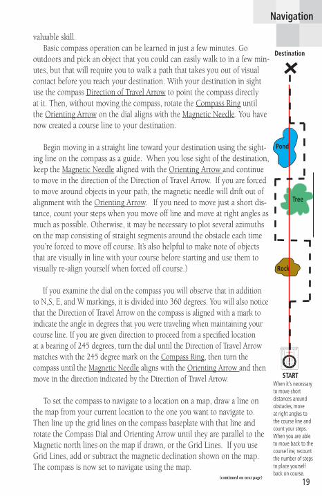
valuable skill. Basic compass operation can be learned in just a few minutes. Go outdoors and pick an object that you could can easily walk to in a few min-utes, but that will require you to walk a path that takes you out of visual contact before you reach your destination. With your destination in sight use the compass Direction of Travel Arrow to point the compass directly at it. Then, without moving the compass, rotate the Compass Ring until the Orienting Arrow on the dial aligns with the Magnetic Needle. You have now created a course line to your destination.
Begin moving in a straight line toward your destination using the sight-ing line on the compass as a guide. When you lose sight of the destination, keep the Magnetic Needle aligned with the Orienting Arrow and continue to move in the direction of the Direction of Travel Arrow. If you are forced to move around objects in your path, the magnetic needle will drift out of alignment with the Orienting Arrow. If you need to move just a short dis-tance, count your steps when you move off line and move at right angles as much as possible. Otherwise, it may be necessary to plot several azimuths on the map consisting of straight segments around the obstacle each time you’re forced to move off course. It’s also helpful to make note of objects that are visually in line with your course before starting and use them to visually re-align yourself when forced off course.)
If you examine the dial on the compass you will observe that in addition to N,S, E, and W markings, it is divided into 360 degrees. You will also notice that the Direction of Travel Arrow on the compass is aligned with a mark to indicate the angle in degrees that you were traveling when maintaining your course line. If you are given direction to proceed from a specified location at a bearing of 245 degrees, turn the dial until the Direction of Travel Arrow matches with the 245 degree mark on the Compass Ring, then turn the compass until the Magnetic Needle aligns with the Orienting Arrow and then move in the direction indicated by the Direction of Travel Arrow.
To set the compass to navigate to a location on a map, draw a line on the map from your current location to the one you want to navigate to. Then line up the grid lines on the compass baseplate with that line and rotate the Compass Dial and Orienting Arrow until they are parallel to the Magnetic north lines on the map if drawn, or the Grid Lines. If you use Grid Lines, add or subtract the magnetic declination shown on the map. The compass is now set to navigate using the map.
Navigation
START
Tree
Rock
Pond
Destination
N30
60120
150210
240
300
330
S
W E
10 20 30 40 50
1�1/2�
READ BEARING HERE
1/16
inch
mm
When it’s necessary to move short distances around obstacles, move at right angles to the course line and count your steps. When you are able to move back to the course line, recount the number of steps to place yourself back on course.
(continued on next page)

20
Navigation
It is important to remember that when sighting on an object and using the compass to travel to it, Magnetic Declination isn’t a factor, but with maps it’s different. Maps are designed with a theoretical (geographic or “True North”) North Pole in mind and the magnetic field that draws your compass needle toward it is located generally in northeastern Canada. So... you need to adjust for the declination when using a map and com-pass. This is again complicated by the fact that the grid systems used to measure locations and distance on maps are placed in accordance with a map datum, which is designed to compensate for irregularities in the shape of the earth in order to create the most accurate map possible. And... the Grid North won’t necessarily match up with True North either. The direc-tion east or west of true north for these values also determines whether you need to add or subtract the declination to make the compass work with your map. To learn about declination compensation, refer to pages 13 and 27 of this manual.
Using a GPS Compass
Almost all Garmin GPS units feature a compass that provides you with directional information but only while you are moving. Several Garmin units (including the GPSMAP 60CS, referenced in this manual) also contain an electronic compass to provide directional information while stationary. The compass functions in the same manner as a regular magnetic compass with the exception that you can select settings for North Reference.
You can choose from Cardinal Letters (N, S, E, W), Degrees (0 to 360), or Mils (there are 6,400 in a circle or 17.78 mils per degree) for the com-pass display and True North, Magnetic North, Grid North, or for special maps projections for which you know the degree of north orientation, User North.
Note that Garmin GPS “User” settings are provided for those individu-als whose knowledge of mapping exceeds the level of discussion in this manual.
GPS units with an electronic compass provide you with north orienta-tion when stationary. These units also contain a feature called “Sight’N Go” which allows you to project a waypoint and then navigate to it from your current position. The electronic compass in the unit performs much the same as a magnetic needle type compass. For best results when using this type compass with a map, set the North Reference to “Magnetic North” and use the compass as you would a magnetic needle type compass.
(continued from page 19)

21
Reading Paper Maps - Map Information
The title for USGS topographic maps is located at the top right corner and is usually named after a significant geographic feature on the map, city, lake, mountain, etc.
Details about who made the map, when it was made, how it was com-piled, the datums used and UTM zone, and other more general notes are usually located at the bottom left margin of the map.
The Map Scale can be found at the center of the bottom margin while a quadrangle location and adjacent quadrangle information is located at the bottom right margin along with Road Classification symbology.
The UTM Grid and Magnetic North Pole Declination graph is located at the Left Bottom margin and is measured from the center of the map.
Magnetic and Grid Declination Graph
Navigation
Heading Page with Magnetic North Reference selected.
Compass Page with Magnetic Compass On.
Magnetic Compass Icon

22
Navigation
4800
4700
4882
UTM Grid Lines (1,000 meter squares)
Contour Lines (shown here at 20 foot intervals)
Highway
High Point with Altitude marked
Man Made Structure
Foot Trail (Marked 4WD when used by vehicles)
Stream
Areas of dense plant growth are marked green
United States Geological Survey (USGS) map markings
Map Scales
Map scale is the relationship between distance on the map and distance on the ground. A map scale is most often expressed as a fraction or ratio. (1/24,000 or 1:24,000) Representative scales mean that one unit of mea-surement (usually 1 inch or 1 centimeter) is equal to 24,000 of the same units on the ground. Road maps typically will indicate 1 inch equals so many miles or 1 cm equals so many kilometers.
The first number of the scale is always 1. The second number on the scale is different for each scale of the map. The larger the number the smaller the map scale. Large scale maps generally display more detail but less area, while small scale maps inversely provide a view of more area with less detail. You may find one of more scale bars indicating the scale length for feet, miles, meters and kilometers. Since contour intervals for topographic maps are usually measured in feet and UTM grids typically use meters to measure distance, conversion factors are also included in the map scale information.

23
Locating Map Items Using Map Tools
Measurement is critical to locating the coordinates of an item on a map, whether its distance or direction. Page 37 contains three map tools which you can copy to a clear transparency suitable for use in a laser printer or standard copier. These tools are for use with maps at 1:24,000 scale (USGS 7.5 minute topographic for example).
The first map tool is a UTM Grid Overlay with a Square Compass Rose. This tool consists of a thousand meter grid square divided into 100 meter increments surrounded by a 360o compass rose (direction template).
The second map tool is a UTM Corner Ruler consisting of two scales at right angles to each other. This type ruler will typically provide a greater degree of precision than the UTM Grid Overlay tool because the scale is divided into 10 meter increments.
The third map tool is the Latitude/Longitude Ruler. If you desire to determine map coordinates in Latitude and Longitude you can measure as precisely as one second intervals or decimally in .01 minute intervals.
Now before you can begin using the tools, you must prepare a 1:24,000 scale map by ruling in the grid lines if you plan to use UTM values. If the compass you plan to use cannot be adjusted for declination, you will need to draw additional magnetic base lines for determining bear-ings with a “magnetic only” compass. If you don’t do this in advance, you will be faced with plotting inaccuracies.
If you are using a USGS 7.5 minute topographic map, you will notice small tick marks around the edge of the map each with a number value assigned. Since current USGS maps do not print the grid lines on the sur-face of the map, you must add them yourself using the tick marks, a thin lead pencil or pen point, and rule long enough to span the map. Use great care in laying in the grid lines both vertically and horizontally, as the more accurately you do this the more accurate your measurements will be. But, to save time for this exercise, we have provided a section of a topo map, to scale, with the grid lines already in place. (see page 28)
All you need to do now is to reproduce the tools on a clear transpar-ency sheet designed for use in a laser printer or copier and cut out your tools. Follow instructions on page 38 which contains the tool images.
Navigation

24
Using the Grid Overlay Tool
Place the grid overlay on the map on page 28, with its edges aligned with the grid lines that surround the map item you want to determine coordinates for. On our map, we have placed a Star to mark the map item. Remember the grid represents a one thousand meter square and the grid overlay breaks that down to a measurement precision of 100 meter squares. After that you can estimate or use the Corner Ruler for more precision. Read to the east (easting) from the left vertical grid line and to the north (northing) up from the bottom horizontal grid line. Follow both of those grid lines to their origin at the edge of the map and observe their numerical value (the large number in the number string: 04 16000M E ...or 04 17 in between the major identifiers, for example).
Now locate the map item within the grid and determine values for its location using the 100 meter lines on the grid overlay (ignore the compass degrees on the outer border of the overlay for now). Once you have measured, you just add the value for easting and northing to the end of the grid line value (it replaces the 000M for major identifiers or adds onto the end of the large number for grid lines between major identifiers). For most land navigation needs, 100 meter accuracy is adequate, but you can measure down to a meter (by adding three digits to the end of the grid line value).
Your measurement should be 0416620 (EAST) 4453190 (NORTH), or thereabout, depending on how well you positioned the grid overlay and estimated the last two digits. Add 12 S to the beginning of this coordinate to place it in Zone 12 and Grid S of the UTM grid and you have a unique coor-dinate for the entire globe. Refer to pages 14 and 15 for more information.
First set your GPS System Setup settings to: Location Format = UTM UPS, Map Datum = NAD27 CONUS (North American Datum 1927 Continental U.S.), and North Reference = Grid to match the USGS topo map. Enter this value into a waypoint on a Garmin GPS (12 S 0416525 4453190) and press the “on-screen” Map key to view the location of this point on the GPS map.
Your GPS should place you on a mountain top just west of Utah Lake near Provo, Utah in the Soldiers Pass Quadrangle. You could easily walk the 900 meters to this peak from the 4WD Jeep Road to the south.
GPSMAP 60CS Unit Settings for compatibility with a 7.5 minute U.S.G.S paper map.
When plotting your position using UTM Grid coordinates, set the North Reference to”Grid”.
Navigation

25
Using the Corner Ruler
If it’s close to one meter accuracy you want, then learn how to use the Corner Ruler to plot your position. The Corner Ruler measures like a Grid Overlay Tool but instead of measuring from the grid line to the map item you measure from the map item to the grid line. Instead of 100 meter increments the Corner Tool uses ten meter increments, which on a 1:24,000 scale map are very close together making pin-point accuracy a bit more difficult.
To plot the location of the map item on page 28, place the corner cross lines on the center of the item and then measure first to the left grid line, and after that, measure down to the bottom grid line. Depending on how squarely you placed the tool on the grid and centered the cross lines on the map item, you should have plotted this position: 12 S 0416625 E- 4453175 N. That’s an improvement of 5 meters easting and 15 meters northing.
Using the Lat/Lon Scale
If you are using latitude and longitude as your unit of measure-ment, then you will want to plot the same position using a 1:24,000 scale latitude/longitude ruler. Remember, latitude and longitude are measured in degrees, minutes and seconds (units divisible by 60). The ruler offers a choice of measurement in .0.01 minute intervals or one second intervals. When you look at the ruler, you will notice that the measurements are from right to left for West Longitude and left to right for East Longitude. You will find the lat/lon markings at the corners of the map, and because we couldn’t fit an entire 7.5 minute map to scale on the page, you will observe only the markings at the upper left corner (40o 15’ 00” latitude and 112o 00’ 00” longitude). If you subtract 7.5 minutes from these values, you will get 40o 07’ 30” latitude at the bottom of the map and 111o 52’ 30”longitude at the right margin of the map. The distance from the left margin to the map item on page 28 is 1 minute 12 seconds and the distance from the top margin to the map item is 1 minute 24 seconds. To plot the position in latitude/longitude, subtract the measurements from the values in the corner of the map. The map item should be located at: North 40o 13’ 36” latitude and West 111o 58’ 48” longitude. If you have a GPS Unit, you can check your measurements by creat-ing a waypoint on your GPS unit using these coordinates and then display it on the Map Page.
USGS Map Item marked as a Waypoint on a Garmin GPSMAP
Navigation
1
7654321
32
45678910
23456789 8765432110
1: 24,000 ScaleCorner Ruler
C 2002 GARMIN, Ltd.
1:24,000Scale
.4 .3 .2 .1 2 .9 .8 .7 .6 .5 .4 .3 .2 .1 .9 .8 .7 .6 .5 .4 .3 .2 .110.01 minute intervals1secondintervals
10" 20" 30" 40" 50" 10" 20" 30" 40" 50" 10" 20" 30"1' 2'c 2002 GARMIN, Ltd.
Latitude/Longitude Scale
Corner Tool

26
Using the Compass Rose
Now that you have determined the location of the map item, you will now need to navigate to it. Unless you know your current location on the map you can’t get there without the help of your GPS unit. The GPS already knows where you are and has the coordinates for the map item. So... all you need to do is call up the map item from the waypoint list and select the ‘GoTo’ function the GPS will provide direct line guidance to the item.
To determine your position without the GPS, you will need a base plate Compass or the Compass Rose on the Grid Overlay. First we will imagine that you are somewhere on the 4WD Road on the map on page 28 and from that location you can observe two recognizable map items, the junction of another 4WD Road and the Lehi to Fairfield Road and an Old Corral that is shown on the map. You don’t need to plot their position, but rather determine the compass bearing from your location to theirs.
If you were actually at this site, imagine that you would take out your compass, sight along the Direction of Travel Arrow toward the road junc-tion, then turn the compass ring until the arrow in the ring aligns with the magnetic needle on the compass. Read the bearing number in degrees at the Direction of Travel Arrow and write it down. Then add both the Magnetic deviation and True North deviation from the reading (which, for this map is 14o 36’) to get a true bearing of 318o. Repeat these steps for the location of the corral. You should end up with bearing of 263o.
The illustration above depicts the reference objects shown on the topo map and how they might appear to you if you were at this location.The UTM Grid North and Magnetic North Declination for this location is shown to the left. To line up with the Grid North lines on the map, subtract the Grid North (GN) and Magnetic North (MN) values (14o 36’) from your compass rose reading. Note: the declination shown to the left was measured in 1993. This value will change periodically, so when using a topo map try to acquire the most recently published version.
UTM GRID AND 1993 MAGNETIC NORTH
DECLINATION AT CENTER OF SHEET
Navigation
Junction of the Lehi to Fairfield Road and a 4WD Road
Corral shown on the Topo Map Your current location on a 4WD Road
★
GN
0o36’
11 MILS
MN
14o
248 MILS

27
On the map, place the Compass Rose center lines over the road junction. Subtract 180 from the 318 degree bearing value to get 138o and project a line with a straightedge from the center of the rose through the 138 degree mark until it intersects the 4WD Road near the bottom of the map. Do the same thing from the Corral by subtracting 180o from 263o to get a bearing of 83o which will project to the 4WD Road and intersect the previous line. This is your location on the map. The two lines are known as Azimuths and the process is called a Triangulation or Resection.
Now that you know where you are, you can use a Base Plate Compass or Compass Rose to set a bearing to the high point on the map located ear-lier. The Grid Bearing from your location is 29o. If you were actually there, and using a compass to magnetically guide you, remember to subtract the magnetic north declination (14o) and Grid North declination (36’) from your Grid North reading in order to get a Magnetic North compass bearing of 15o.
NOTE: If the Grid North declination is east of True North, you would then add rather than subtract and if your Magnetic North declination is west of True North then you would also add that value. A simple rule to follow is: “Declination east, declination least. Declination west, declination best.” Meaning, subtract east declination and add west declination.
Set the compass ring to place that value at the Direction of Travel Arrow line and then line up the arrow on the dial with the magnetic needle and then walk in the direction of the Direction of Travel Arrow. You are a little less than 1,000 meters from the high point marked 5208 and even being that close you will have difficulty keeping on your bearing, given trying to keep the magnetic and dial needles in sync and sighting along the Course Line, not to mention obstacles in your path. Often it is best to sight in on an object that is on your course line and just a short distance ahead, then you can focus on it instead of your compass and then take another reading when you reach that point, sighting in a new object to walk to.
Navigation
9876
4
210
3
2002 GARMIN Ltd.c
1:24,000 UTM Grid100 Meter Increments
0355340
275
335 345
295
305
330
280
325
290
300
285
320
220 215 210 205 200 190195 185 175 170 165 160 155 150 145 140 135
130125
120115
110105
10095
9085
8075
7065
6055
50
45403530252015105
180
315
310
270
350
245
265
250
260
255
240
235
230
225
N
W E
S0 1 2 3 4 5 6 7 8 9
5To determine your current location on a map, first use a compass to sight bearings from your current location to two identifiable land features that are also shown on the map. Then use a compass rose scaled for that map (much like that shown to the right) and project a line from each object along the two bearings. When those line cross, they should make your approximate position on the map. Accuracy will be dependent upon your compass sighting and map tool skills.
Transparent Compass Rose (Map Tool)
Your current location
Bearing from an observable land feature
USGS Topo Map
N30
60
120150
210
240
300330
S
W
E
1020
3040
50
1�1/2�
READ
BEARINGHER
E
1/16 inch
mm
Junction of the Lehi to Fairfield Road and a 4WD Road
Corral shown on the Topo Map Your current location on a 4WD Road
★
GN
0o36’
11 MILS
MN
14o
248 MILS

28
Navigation
★
Grid Line 0416000 meters E
Grid
Line
4453
000
met
ers N
USGS 7.5 Minute Quadrangle Topographic Map at 1:24,000 Scale located within Zone 12 Grid S of the Universal Transverse Mercator Grid
Lehi
to Fa
irfiel
d Ro
ad
Grid North bearing to the Corral is 263o
Your current Location on the 4WD road.
Bearing to this point from your current Location on the 4WD road is 29
o
Grid North and 15o Magnetic North
Grid North bearing to the Junction of a 4WD road and the Lehi to Fairfield Road is 318o
✠
Grid North
Magnetic North
☞Find the coordinates for this high point in the landscape!
14o
29o
15o

29
Navigation
How a GPS simplifies map navigation
If you find the instructions for using map and compass on the previous pages confusing and complicated, they are. That’s why an electronic naviga-tion computing device is so much more convenient. A GPS makes the proper adjustment calculations and gets the math right. Using a GPS receiver, con-stantly corrects for any deviation from the bearing line and on most Garmin units, provides you with Course Deviation Indication (CDI), telling you how far you have moved to the left or right of your course bearing. Because your GPS can factor the magnetic heading to compensate for the North declina-tion, once you have chosen a destination to ’GoTo’, the GPS will always point you in the right direction. That is, provided you have also chosen a position format and map datum to match that of the map as well.
Compass Page with Course Pointer active.
Course Deviation Indicator(CDI) Scale
Heading Setup Page with Compass Display, North Reference, and Magnetic Variation selection fields..
Units Setup Page with Position Format, Map Datum, and Units of Measure selection fields.
Go To navigation on the Map Page displaying the direct route to a destination.

30
GPS Accuracy
All in all, your GPS unit does a pretty good job, measuring your eleva-tion to within a few hundred feet and your horizontal location to within a few yards, but this can vary depending on conditions which affect signals, so there isn’t a standard percentage of accuracy that you can reliably predict. The best solution for this, if altitude measurement is important to you, is to purchase a Garmin GPS with a built-in altimeter, such as an eTrex Summit, eTrex Vista, or GPSMAP 60CS. Here are current values for Garmin GPS accuracy:
GPS unit unassisted (U.S. DoD Selective availability turned Off): Less than 15 meters (49 feet)
GPS with U. S. Coast Guard Differential Beacon input: 3 to 5 meters (10 to 16 feet)
GPS with Wide Area Augmentation System (WAAS) capability turned on: 3 meters (10 feet)
A topographic map can help you determine your elevation within a few feet and GPS units with built-in altimeters allow you to re-enter a more accurate elevation and then uses that value as a basis for measurement. Remember set your GPS Units of Measurement to match the vertical units used on your map but don’t confuse this with horizontal measurement. UTM grids are measured in meters while contour increments are most often measured in feet. The Garmin GPS has provisions for setting both vertical and horizontal units of measurement.
Map Accuracy
Since the question of accuracy is being discussed, you might want to know how accurate a USGS 7.5 minute topo map might be. 1:24,000 scale, 7.5 minute topo maps take approximately 5 years to develop and 90% of the measurable points, both horizontal and vertical, are checked for accuracy. For horizontal accuracy the maximum error allowed is 40 feet, and for vertical accuracy, the maximum error allowed is 1/2 the distance of a contour level. So... on a map with twenty foot contour intervals the greatest error in elevation would be ten feet.
Keep in mind that we’re talking about USGS maps of a certain type, and that not all maps are constructed to the same standards. If map accuracy is important to you, then some research on your part is in order. Some of the web sites listed in the Appendix may have answers to your questions.
Navigation

31
Glossary of Map and GPS Terminology
Before you begin using a map and a GPS, here is a short glossary of terms it will be helpful to understand:
Azimuth - The horizontal angle of deviation, measured clockwise for a bearing of standard direction (eg. North).
Bearing - A direct line (course) of travel measured in compass degrees from a point of origin to a destination.
CDI - (Course Deviation Indicator) With respect to Garmin GPS units, a graphic display and distance value indication of when and how far off your intended course you have traveled.
Contour Lines - Lines on a map connecting points of equal elevation above mean sea level allowing relief features to be profiled into a three dimensional perspective.
Elevation - The vertical distance from a datum (usually mean sea level) to a point or object on the earth’s surface.
Horizontal Datum - The positional reference or basis for the geo-graphic location of features on a map.
Magnetic Declination - The angle between magnetic north and true north, expressed in degrees and minutes, east of west from true north.
Magnetic North - The direction to which a compass needle points.
Mean Sea Level - The average height of the surface of the sea for all stages of tide, used as a reference surface from which elevations are measured.
Topography - Surface features both natural and cultural, collectively depicted on topographic maps.
True North - The direction of the northern rotational axis of the earth - the North Pole.
GMT - (Greenwich Mean Time) The mean solar time of the meridian of Greenwich (England) used as the prime basis for time throughout the world.
GPS - (Global Positioning System) The official name for the system of satellites that encircle the earth to provide navigation information for global positioning of any device that can receive the broadcast radio signals from those satellites and compute its location using a built-in almanac and calculating database. Actually the term GPS, when used to describe a Garmin product is a reference to a radio receiver with sophisticated computing and mapping capabilities.
Appendix A

32
Grid - A system for dividing the earth into measurable sections by projecting it onto a flat plane to allow measurement of locations on its surface. There are many grid systems, with the Universal Transverse Mercator (UTM) being the most widely used.
Datum - A reference system for computing or correlating the results of surveys. There are two principal types of datums: vertical and hori-zontal. A vertical datum is a level surface to which heights are referred. An example would be Mean Sea Level. A horizontal datum is used as a reference for position and defined by: the latitude and longitude of an initial point, the direction of a line between this point and a specified second point, and two dimensions which define the spheroid.
Ephemeris - A table of predicted satellite orbital locations for specific time intervals contained in the database of your GPS unit. This table helps to characterize the conditions under which data signals from the satellites in orbit around the earth are received by your GPS unit. The satellites are travelling at speeds of 7,000 miles an hour, which allows them to circle the earth once every 12 hours. This table helps the satel-lite to make corrections in flight, an important part of insuring accurate data collection for determining your position on the earth when using a GPS receiver.
Geodetic - That part of applied mathematics that deals with the determination of the magnitude and shape of either the whole Earth or of a large portion of its surface. Also refers to the exact location points on the Earth’s surface.
Landform - A naturally occurring object on the surface of the land, such as a hill, creek bed, ridge, sink hole, etc. Best depicted by the contour lines shown on topographic maps.
Mercator Projection - A conformal map projection of the earth. It preserves angular relationships. It was designed for navigational use and is the standard for marine charts.
NGS - The National Geodetic Survey is the United States oldest civil-ian scientific agency. It was reorganized in 1970 creating the National Oceanic and Atmospheric Administration (NOAA) and the National Ocean Service (NOS).
NIMA - The National Imagery and Mapping Agency - The primary function of this agency is to provide timely, relevant, and accurate Geospatial Intelligence in support of national security. As a result it partner’s with industry to develop this intelligence from a multitude of
Appendix A

33
Appendix A
sources and technologies.
NOAA - The National Oceanic and Atmospheric Administration cre-ated in 1970 is the first agency formed for the observation and study of the atmosphere and conservation of natural resources. This agency and its descendants have become recognized as world leaders in the sciences of geodesy, geophysics, metrology, oceanography, meteorology, climatology, marine biology, and marine ecology.
Projection - An orderly system of lines on a plane representing a corresponding system of imaginary lines on a terrestrial datum surface. For the Earth, a projection consists of lines representing parallels of latitude and meridians of longitude or a grid.
Topographic Maps - These maps display the topography of the land using contour lines to depict elevation and color to depict water, fores-tation, roads, and other features.
USGS - (United States Geological Survey) The US Government Agency responsible for gathering and publishing data about the geography of the United States which includes maps depicting information about topography, natural resources, state and national atlas, national parks, etc.
UTM Grid - (Universal Transverse Mercator Grid) A mercator type mapping projection with the cylinder positioned on the equatorial axis of the earth (horizontally).
Waypoint - A landmark, point of destination or point along a route on one’s way (hence; waypoint) noted and recorded using mapping or navigation coordinates.

34
Canadian Topographic Maps - Canadian National Topographic System - http:// maps.nrcan.gc/topographic.html
Compass, Basic Operation and Bearings - Alberta, Canada WorldWeb Travel Guide
- http://www.discoveralberta.com/Article/WildernessNavigation/8-39.html
Datums and Projections: A Brief Guide - Princeton University - http://www.princeton.edu/~oa/manual/mapcompass.shtml
Finding Your Way with Map and Compass - United States Geological Survey
- http://mac.usgs.gov/mac/isb/pubs/factsheets/fs03501.html
Geodesy for the Layman - National Imagery and Mapping Agency - http://nima.mil/GandG/geolay/TR80003A.HTM
GIS - Geographic Information Systems
- http://www.gisportal.com/
GPS Coordinate Explanation - Lightning Paddles, Inc.
- http;//www.paddles.com/users/wildcamp/coordexp.html
GPS Hints - Wild Rose GPS Maps
- http://www.okon.com/gps.html
GPS/Map Position Datum & Coordinate Settings - University of Arkansas
- http://www.uaex.edu/Other_Arena/publications/HTML/FSA-1032.asp
Map Accuracy - United States National Map Accuracy Standards
- http://mac.usgs.gov/mac/isb/pubs/gactsheets/fsh199.html
Maps, Compasses and GPS’s 101, A Basic Course - GPS Enthusiasts Webring
- http://www.gpsnuts.com/mygps/gps/tutorials/maps/maps.htm
Map Projections - United States Geological Survey
- http://mac.usgs.gov/mac/isb/pubs/MapProjections/projections.html
Map Reading - OA Guide to Map and Compass, Part 1, Princeton University
- http://www.princeton.edu/~oa/manual/mapcompass.shtml
Map Scales - United States Geological Survey
- http://mac.usgs.gov/mac/isb/pubs/factsheets/fs01502.html
NIMA - National Imagery and Mapping Agency
- http://www.nima.mil
Index of Web sites by Topic
Appendix B

35
Appendix B
Here is series of excellent navigation articles by John Milne on GORP:
Another Way to Find Yourself, Latitude and Longitude
- http://www.gorp.com/gorp/activity/hiking/skills/navigation/utm.htm
Another Way to Find Yourself, More on Waypoints
- http://www.gorp.com/gorp/activity/hiking/skills/navigation/utm2.htm
Another Way to Find Yourself, UTM and Maps
- http://www.gorp.com/gorp/activity/hiking/skills/navigation/utm3.htm
Calculating Global Position, Map Datum
- http://www.gorp.com/gorp/activity/hiking/skills/navigation/datum.htm
Getting There with GoTo, Let GPS Steer You Right
- http://www.gorp.com/gorp/activity/hiking/skills/navigation/goto.htm
Latitude and Longitude, In the Beginning
- http://www.gorp.com/gorp/activity/hiking/skills/navigation/lat_lon2.htm
Making Sense of North, East is Least and West is Best
- http://www.gorp.com/gorp/activity/hiking/skills/navigation/north2.htm
Making Sense of North, When North isn’t
- http://www.gorp.com/gorp/activity/hiking/skills/navigation/north.htm
Staying On Course, Route Planning with GPS
- http://www.gorp.com/gorp/activity/hiking/skills/navigation/route.htm
Where Are You?, In the Beginning
- http://www.gorp.com/gorp/activity/hiking/skills/navigation/lat_lon3.htm
Important Note: Garmin, Ltd. is not responsible for the content or maintenance of information contained on the above mentioned web sites. These web sites contained information, in the public domain, related to subjects discussed in the manual at the time of its writing.
NOAA - National Oceanic and Atmospheric Administration
- http://www.noaa.gov/
USGS Home Page - United States Geological Survey
- http://mac.usgs.gov/
USGS Topographic Maps - United States Geological Survey
- http://mac.usgs.gov/mac/isb/pubs/booklets/usgamaps/usgamaps.html
Universal Transverse Mercator (UTM) Grid - U. S. Geological Survey
- http://mac.usgs.gov/mac/isb/pubs/factsheets/fs07701.html
36
Garmin GPS Selection Guide
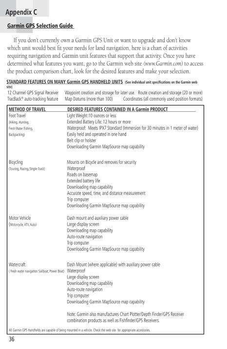
If you don’t currently own a Garmin GPS Unit or want to upgrade and don’t know which unit would best fit your needs for land navigation, here is a chart of activities requiring navigation and Garmin unit features that support that activity. Once you have determined what features you want, go to the Garmin web site (www.Garmin.com) to access the product comparison chart, look for the desired features and make your selection.
METHOD OF TRAVEL DESIRED FEATURES CONTAINED IN A Garmin PRODUCT Foot Travel Light Weight:10 ounces or less(Hiking, Hunting, Extended Battery Life: 12 hours or moreFresh Water Fishing, Waterproof: Meets IPX7 Standard (Immersion for 30 minutes in 1 meter of water)Backpacking) Easily held and operated in one hand Belt clip or holster Downloading Garmin MapSource map capability
Bicycling Mounts on Bicycle and removes for security(Touring, Racing, Single-Track) Waterproof Roads on basemap Extended battery life Downloading map capability Accurate speed, time, and distance measurement Trip computer Downloading Garmin MapSource map capability
Motor Vehicle Dash mount and auxiliary power cable(Motorcycle, ATV, Auto) Large display screen Downloading map capability Auto-route navigation Trip computer Downloading Garmin MapSource map capability
Watercraft Dash Mount (where applicable) with auxiliary power cable( Fresh water navigation Sailboat, Power Boat) Waterproof Large display screen Downloading map capability Auto-route navigation Trip computer Downloading Garmin MapSource map capability
Note: Garmin also manufactures Chart Plotter/Depth Finder/GPS Receiver combination products as well as Fishfinder/GPS Receivers.
All Garmin GPS Handhelds are capable of being mounted in a vehicle. Check the web site for appropriate accessories.
STANDARD FEATURES ON MANY Garmin GPS HANDHELD UNITS (See individual unit specifications on the Garmin web site)
12 Channel GPS Signal Receiver Waypoint creation and storage for later use. Route creation and storage (20 or more) TracBack® auto-tracking feature Map Datums (more than 100) Coordinates (all commonly used position formats)
Appendix C

37
Appendix D
9876
4
210
3
2002 GARMIN Ltd.c
1:24,000 UTM Grid100 Meter Increments
035534027
5335 345
295
305
33028
0325
290
300
285
320
220 215 210 205 200 190195 185 175 170 165 160 155 150 145 140 135
130125
120115
110105
10095
9085
8075
7065
6055
50
45403530252015105
180
31531
027
0350
245
265
250
260
255
240
235
230
225
N
W E
S0 1 2 3 4 5 6 7 8 9
5
1:24,000 Scale
.4.3
.2.1
2.9
.8.7
.6.5
.4.3
.2.1
.9.8
.7.6
.5.4
.3.2
.11
0.01
minuteintervals
1second
intervals10"
20"30"
40"50"
10"20"
30"40"
50"10"
20"30"
1'2'
c2002
GAR
MIN, Ltd.
Map Grid and Square Compass Rose
1
7654321
32
45678910
23456789 8765432110
1: 24,000 ScaleCorner Ruler
C 2002 GARMIN, Ltd.
Corner Ruler
Inches
Centimeters
Instructions: to make your own map tools for 1:24,000 scale maps you can copy this page onto a clear overhead transparency sheet. To insure that your copy is relatively accurate, match the scale below to a quality ruler. If your copy is too large or too small, adjust the copier enlarge/reduce setting accordingly. Even then, expect a small amount of distortion.
0 1 2 3
0 1 2 3 4 5 6 7
Latitude/Longitude Ruler
Map Tools

38
Satellite Geometry, and why your horizontal location is reported more accurately by your GPS than your elevation (vertical location).
Satellite geometry sounds a bit technical, and it is in application. But for purposes of understanding why a GPS unit will report your horizontal (ground) position more accurately than your vertical position (height above the mean surface of the earth), it isn’t necessary to go into much detail. As previously explained, there are 27 Navistar satellites circling the earth in precise orbits, 24 of which, are in constant service. For a GPS receiver to provide you with accurate data about your position in three dimensions, it needs to gather data from at least four satellites.
If at least three of those satellites are in close proximity to the horizon and at nearly opposite positions from your location, you stand the best chance for very accurate horizontal position reporting. The larger the triangle formed by these satellites the better your GPS unit can calculate your horizontal position, because these satellites provide measurement from front, back, and side (roughly opposite each other) making for more accurate measurement. Satellites grouped overhead in a tight triangle would produce a less accurate position report because the distance of measurement doesn’t change very much.
If you view the Satellite page of a Garmin GPS you will see a graphic display of the satellites being received (up to 12 simultaneously) and their relative position in the sky overhead. The inner ring of the display rep-resents an overhead orientation while the outer ring, the horizon around your location. Just by observing the location of satellites on the display can provide you with a feel for how accurately your position is being reported. Plus... the page also posts an accuracy statement.
Measuring your vertical position (elevation) with great accuracy is not so easy, as this requires satellites to be positioned above and below you. There will always be satellites above and below you, but those below have their signals blocked by the earth.
Satellites nearer to the horizon can measure your horizontal position with much greater accuracy.
Satellite directly overhead which tries to measure your elevation, but isn’t aided by measurements from the other direction.
Satellite signals blocked by the earth
Your GPS Receiver
Appendix E

39
Appendix F
Using Garmin GPS units equipped with barometric altimeters
Many Garmin GPS units are equipped with a barometric pressure sensor (such as the GPSMAP 60CS) that uses that information to determine your current elevation as displayed on the Altimeter Page. When properly calibrated, this altimeter can measure altitude with much more accuracy than the GPS receiver.
In addition, this feature can display both pressure and elevation plots providing pressure over time and elevation over distance profiles. These plots provide you with a method for tracking potential weather changes and a view of the terrain you have traversed. Individual points can be viewed as well as on the Map Page.
If you are using a Garmin product compatible with Garmin MapSource 24k Topographic Maps, you can create a route in an area covered by a 24k map and view the elevation profile before you begin your trek. This type of profile is of great value if hiking in mountainous terrain as the horizontal distance to your destination can be compounded by the vertical ascents and descents on your route. It could actually take more time to negotiate than would appear, if viewed only as a horizontal track.
Altimeter Page displaying an Elevation over Distance Profile
Altimeter Page displaying a Pressure over Time Profile

40
© 2005 Garmin, Ltd. and its subsidiaries
Garmin International, Inc. 1200 East 151st Street, Olathe, Kansas 66062, U.S.A.
Garmin (Europe) Ltd. Unit 5, The Quadrangle, Abbey Park Industrial Estate, Romsey, SO51 9DL, U.K.
Garmin Corporation
No. 68, Jangshu 2nd Rd., Shijr, Taipei County, Taiwan
www.Garmin.com
Part Number 190-00225-00 Rev. B