Embed Size (px)
Citation preview

Electronic MetronomeUsing a 555 Timer
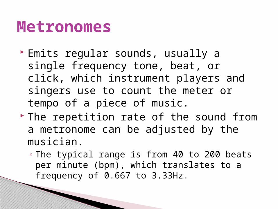
Emits regular sounds, usually a single frequency tone, beat, or click, which instrument players and singers use to count the meter or tempo of a piece of music.
The repetition rate of the sound from a metronome can be adjusted by the musician.◦ The typical range is from 40 to 200 beats per minute
(bpm), which translates to a frequency of 0.667 to 3.33Hz.
Metronomes
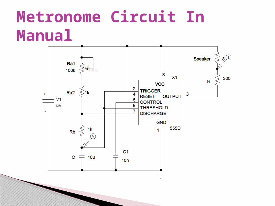
Metronome Circuit In Manual
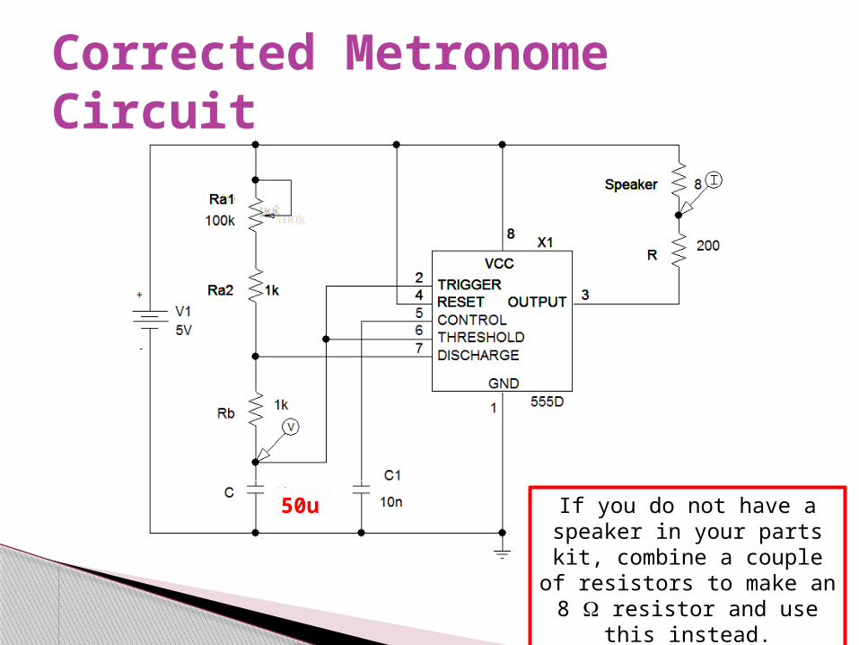
Corrected Metronome Circuit
50u If you do not have a speaker in your parts kit, combine a couple
of resistors to make an 8 W resistor and use this instead.
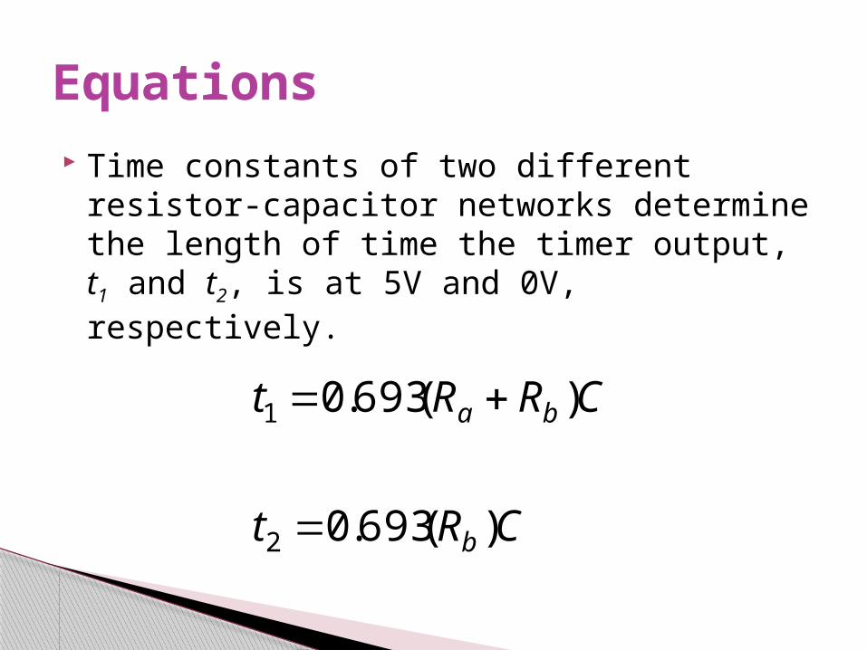
Time constants of two different resistor-capacitor networks determine the length of time the timer output, t1 and t2, is at 5V and 0V, respectively.
Equations
CRt
CRRt
b
ba
)(693.0
)(693.0
2
1
Fixed Capacitors◦Nonpolarized May be connected into circuit with either terminal of capacitor
connected to the high voltage side of the circuit. Insulator: Paper, Mica, Ceramic, Polymer
◦ Electrolytic The negative terminal must always be at a lower voltage than
the positive terminal Plates or Electrodes: Aluminum, Tantalum
Types of Capacitors
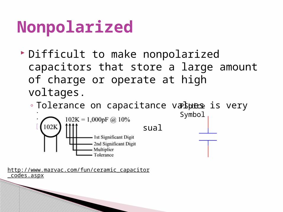
Difficult to make nonpolarized capacitors that store a large amount of charge or operate at high voltages.◦ Tolerance on capacitance values is very large +50%/-25% is not unusual
Nonpolarized
http://www.marvac.com/fun/ceramic_capacitor_codes.aspx
PSpice Symbol
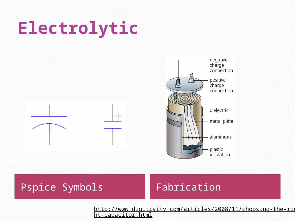
Electrolytic
Pspice Symbols Fabrication
http://www.digitivity.com/articles/2008/11/choosing-the-right-capacitor.html
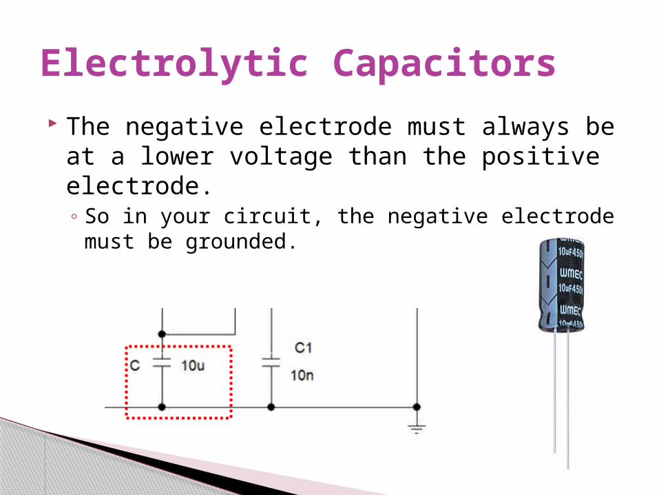
The negative electrode must always be at a lower voltage than the positive electrode.◦ So in your circuit, the negative electrode must be grounded.
Electrolytic Capacitors
ba
b
ba
RR
R
tt
tD
CRRttf
2
)2(
44.11
21
2
21
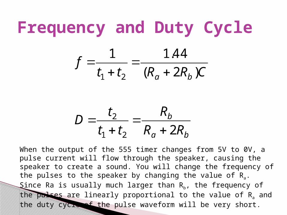
Frequency and Duty Cycle
When the output of the 555 timer changes from 5V to 0V, a pulse current will flow through the speaker, causing the speaker to create a sound. You will change the frequency of the pulses to the speaker by changing the value of Ra. Since Ra is usually much larger than Rb, the frequency of the pulses are linearly proportional to the value of Ra and the duty cycle of the pulse waveform will be very short.
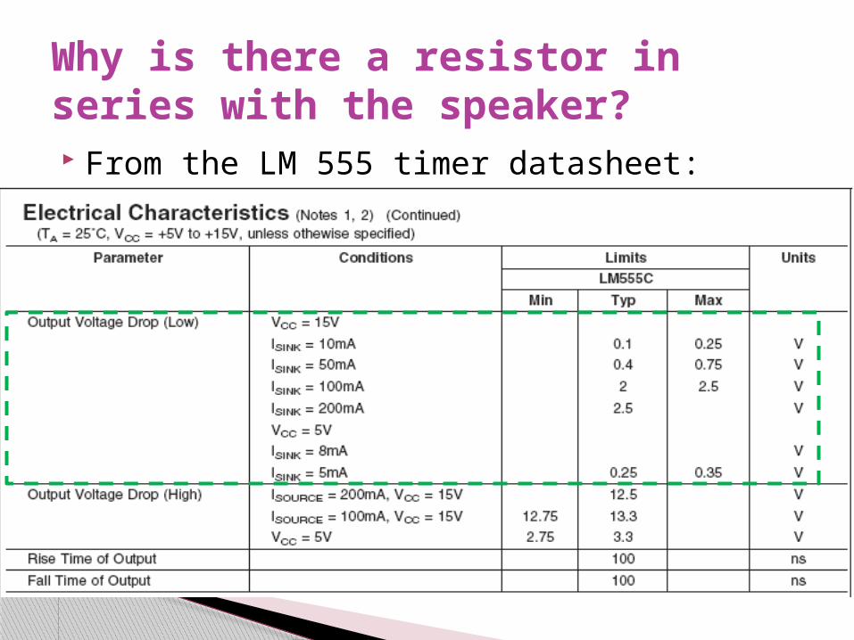
From the LM 555 timer datasheet:
Why is there a resistor in series with the speaker?
When a component sinks current at its output, current is defined as positive when entering the component from the external circuitry.
When a component sources current at its output, current is defined as positive when it leaves the component and flows into the external circuitry.◦ In a 555 timer, the output voltage is limited to 0 V – Vcc, which is +5 V in
the circuit for our experiment.◦ In the metronome circuit, current only flows when the output voltage is
less than Vcc, which forces current to flow into the 555 timer at the output terminal. The 555 timer will sink current. The 200 W resistor acts as a current limiting resistor to insure that the current
sunk into the 555 timer will not exceed the maximum current allowed according to the datasheet.
Sink versus Source
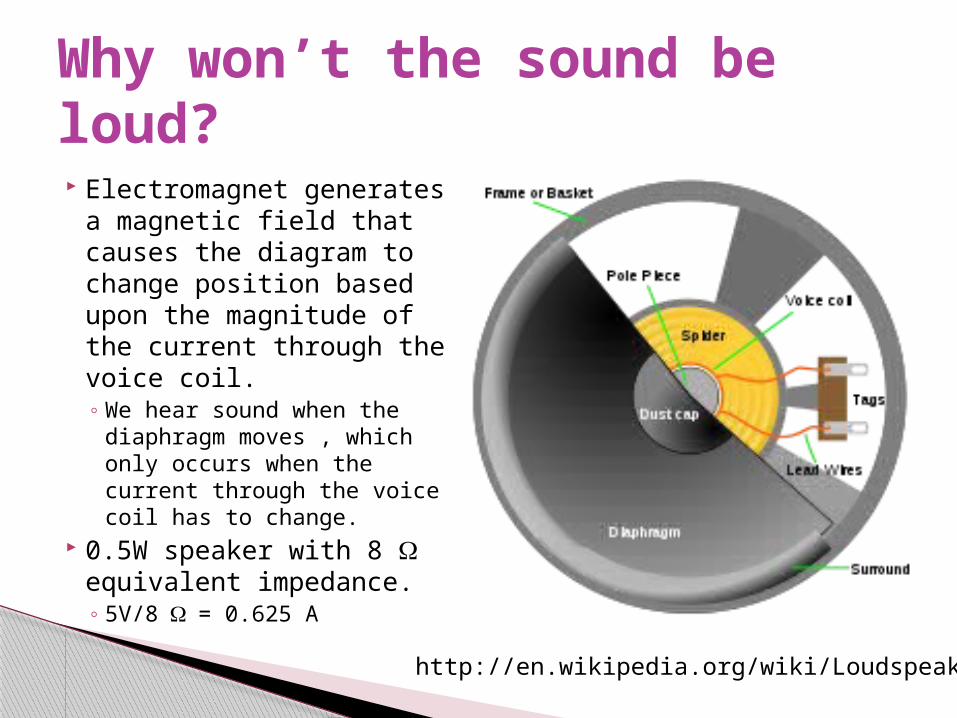
Electromagnet generates a magnetic field that causes the diagram to change position based upon the magnitude of the current through the voice coil. ◦ We hear sound when the
diaphragm moves , which only occurs when the current through the voice coil has to change.
0.5W speaker with 8 W equivalent impedance.◦ 5V/8 W = 0.625 A
Why won’t the sound be loud?
http://en.wikipedia.org/wiki/Loudspeaker
Is requested in the laboratory procedure. However, the value of the capacitor used in this experiment is beyond the capability of the DMM.◦ Ignore this step.
Measurement of Capacitance
The ground for the arbitrary function generator and both channels of the oscilloscope are connected and are tied to earth ground.◦ To determine the voltage across the speaker and the
current flowing through it will require some thought.
Measurement Issue
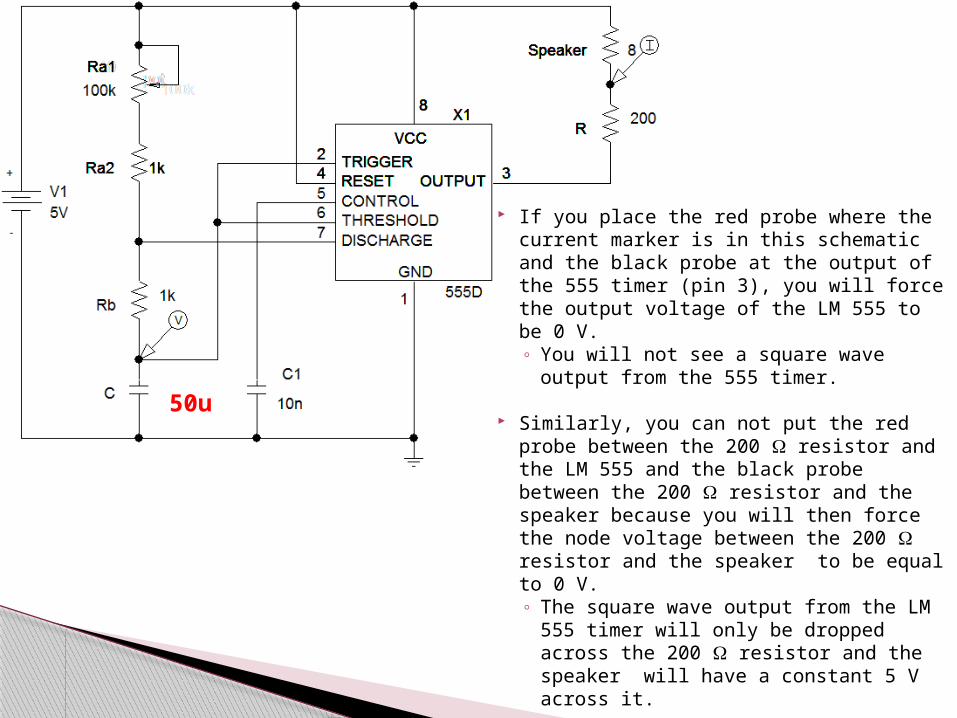
If you place the red probe where the current marker is in this schematic and the black probe at the output of the 555 timer (pin 3), you will force the output voltage of the LM 555 to be 0 V. ◦ You will not see a square wave output
from the 555 timer.
Similarly, you can not put the red probe between the 200 W resistor and the LM 555 and the black probe between the 200 W resistor and the speaker because you will then force the node voltage between the 200 W resistor and the speaker to be equal to 0 V.◦ The square wave output from the LM
555 timer will only be dropped across the 200 W resistor and the speaker will have a constant 5 V across it.
50u
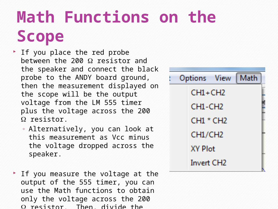
Math Functions on the Scope If you place the red probe between the 200 W
resistor and the speaker and connect the black probe to the ANDY board ground, then the measurement displayed on the scope will be the output voltage from the LM 555 timer plus the voltage across the 200 W resistor. ◦ Alternatively, you can look at this
measurement as Vcc minus the voltage dropped across the speaker.
If you measure the voltage at the output of the 555 timer, you can use the Math functions to obtain only the voltage across the 200 W resistor. Then, divide the result by the resistance to find the current.◦ A similar technique can be used to
determine the voltage across the speaker.

![Example 12.18 Analyzing Classical Form first movement, 26–47 · Allegro 1 2 G [Transition] 555555!5 555 55555555 555!555544 0 5 5555!5555 3 3 3 G 555555!5 555 5 555 5 555 5 555](https://img.pdfslide.us/doc/110x75/5eb9b97f2a57427eb12edee5/example-1218-analyzing-classical-form-irst-movement-26a47-allegro-1-2-g-transition.jpg)