Embed Size (px)
Citation preview
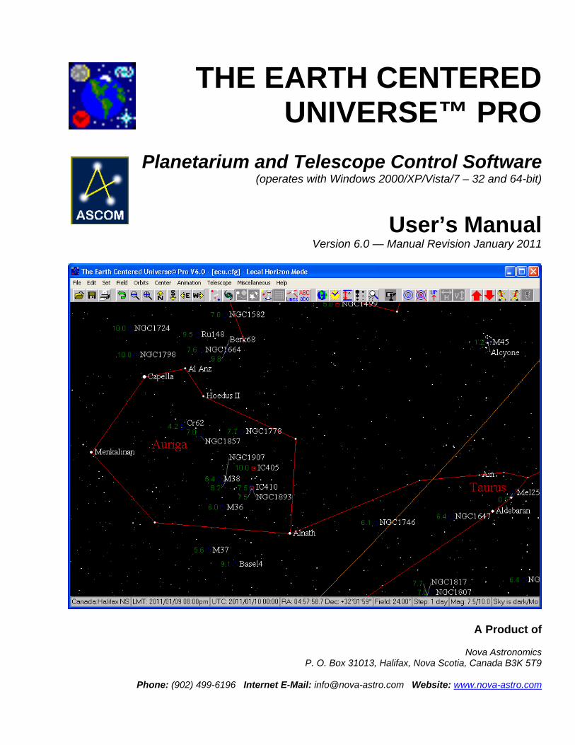
THE EARTH CENTERED
UNIVERSE™ PRO
Planetarium and Telescope Control Software (operates with Windows 2000/XP/Vista/7 – 32 and 64-bit)
User’s Manual Version 6.0 — Manual Revision January 2011
A Product of
Nova Astronomics P. O. Box 31013, Halifax, Nova Scotia, Canada B3K 5T9
Phone: (902) 499-6196 Internet E-Mail: [email protected] Website: www.nova-astro.com
License Agreement
If you, the licensee, have purchased a license to use the Earth Centered Universe Pro (ECU) (the “Software”), or upgraded from a previous version of the Software, by sending Nova Astronomics the appropriate fee or by purchasing from a retailer, and you are in possession of a registration number and license key, you are granted a non-exclusive license to install and use one copy of the Software on one computer for use by any one person at a time. You are additionally permitted to install and use the Software on a second computer, provided this second computer is owned by the licensee or used exclusively by the licensee (for example, a notebook computer used in the field or a computer used at your place of work), and there is no possibility of the Software being used on both computers at the same time. You may not loan or rent the Software to others. If you purchased or received the Software as an upgrade of an earlier version, you may not continue to use the earlier version, nor may you sell or give away the previous version of the Software. If used on a network, provisions must be made to restrict simultaneous use of the Software to the number of copies purchased or to abide by the terms of a separate site license agreement or license certificate. Reasonable backup copies are permitted. The transfer of this license may be made at any time by notifying Nova Astronomics.
Trademarks and Copyrights
The Earth Centered Universe (ECU) software is protected by the copyright laws of Canada and the United States of America, as well as by the copyright laws of many other countries pursuant to international treaties. The ECU software and this manual are Copyright © 1992-2011 by David J. Lane (the owner of Nova Astronomics) and its licensors. All rights reserved. No part of the ECU computer program, documentation, or related files may be copied, reproduced, photocopied, or transmitted except as provided by the license agreements below. “ECU”, “The Earth Centered Universe”, and “Micro-Guider” are trademarks of Nova Astronomics. Other trademarks are the trademarks of their respective trademark owners.
Limited Warranty
This software and manual are distributed and licensed on an “as is” basis. Defective media will be replaced free-of-charge for a period of ninety (90) days from the date that you received the software. Should you encounter problems with the software, Nova Astronomics’ entire liability shall be, at the sole option of Nova Astronomics, either (a) to terminate the license and return any license fees that you paid to Nova Astronomics for the software, or (b) repair or replace the software. Nova Astronomics makes no claims as to the suitability of this software for any specific use. In no event shall Nova Astronomics be liable for any damages whatsoever arising out of the use of this software.
GUIDE STAR CATALOG NOTICES (applies to the NASA Guide Star Catalog included
on the “Earth Centered Universe” CD-ROM)
Copyright Notice The Guide Star Catalog (GSC), version 1.1 is copyrighted by the Association of Universities for Research in Astronomy, Inc., and is reproduced here by permission. The scientific efforts leading up to the production of the GSC are described in Volume 99, pp. 2019-2154 of the Astronomical Journal and in text files on the CD-ROM version of the GSC from which data contained herein were extracted.
Warranty Disclaimer
NOVA ASTRONOMICS’ LICENSOR MAKES NO WARRANTIES, EXPRESS OR IMPLIED, INCLUDING WITHOUT LIMITATION THE IMPLIED WARRANTIES OF MERCHANTABILITY AND FITNESS FOR A PARTICULAR PURPOSE, REGARDING THE GSC OR ITS USE AND OPERATION FOR ANY PURPOSE. THE EXCLUSION OF IMPLIED WARRANTIES IS NOT PERMITTED BY SOME JURISDICTIONS. THE ABOVE EXCLUSION MAY NOT APPLY TO YOU.
Disclaimer of Liability IN NO EVENT WILL NOVA ASTRONOMICS’ LICENSOR, AND ITS DIRECTORS, OFFICERS, EMPLOYEES, OR AGENTS (COLLECTIVELY NOVA ASTRONOMICS’ LICENSOR) BE LIABLE TO YOU FOR ANY CONSEQUENTIAL, INCIDENTAL, OR INDIRECT DAMAGES ARISING OUT OF OR IN CONNECTION WITH THE USE OF THE GSC EVEN IF LICENSOR HAS BEEN ADVISED OF THE POSSIBILITY OF SUCH DAMAGES. BECAUSE SOME JURISDICTIONS DO NOT ALLOW THE EXCLUSION OR LIMITATION OF LIABILITY FOR CONSEQUENTIAL OR INCIDENTAL DAMAGES THE ABOVE LIMITATION MAY NOT APPLY TO YOU. Nova Astronomics’ Licensor’s liability to you for actual damages from any causes whatsoever, and regardless of the form of the action (whether in contract, tort (including negligence), product liability or otherwise), will be limited to US$50.
TABLE OF CONTENTS
1. Getting Started ................................................................................................8 1.1 System Requirements ..........................................................................8 1.2 Installation Instructions .........................................................................9 1.3 Starting ECU.......................................................................................10
2. Introduction ...................................................................................................11 2.1 The Status Information Displays.........................................................11 2.2 The Sky Display..................................................................................12 2.3 Mouse Operations ..............................................................................13
2.3.1 Left Mouse Button.................................................................13 2.3.2 Right Mouse Button ..............................................................14 2.3.3 Shift Key ...............................................................................14 2.3.4 Control Key ...........................................................................14
2.4 On-Screen Controls............................................................................15 2.5 Keyboard Quick Keys .........................................................................18
3. Menu Selections............................................................................................19 3.1 File Menu............................................................................................20
3.1.1 Open .....................................................................................20 3.1.2 Save......................................................................................20 3.1.3 Save As ................................................................................20 3.1.4 Revert ...................................................................................21 3.1.5 Restore Defaults ...................................................................21 3.1.6 Print Chart.............................................................................21 3.1.7 Printer Setup.........................................................................21 3.1.8 Chart Setup...........................................................................22 3.1.9 Set Printer Fonts ...................................................................23 3.1.10 Save Object Report.............................................................24 3.1.11 Report Settings ...................................................................24 3.1.12 Exit......................................................................................25
3.2 Edit Menu ...........................................................................................25 3.2.1 Undo .....................................................................................25 3.2.2 Enable Multiple Undos ..........................................................25 3.2.3 Toolbar On............................................................................25 3.2.4 Autowrap Toolbar..................................................................25 3.2.5 Scroll Bars On.......................................................................26 3.2.6 Scroll Bar Mode ....................................................................26 3.2.7 Track Coordinates.................................................................26 3.2.8 Faster Drags .........................................................................26 3.2.9 Status Line On ......................................................................26 3.2.10 Status Line..........................................................................26 3.2.11 No Status Box.....................................................................26 3.2.12 Small Status Box.................................................................26 3.2.13 Large Status Box ................................................................27
3.3 Set Menu ............................................................................................27 3.3.1 Time......................................................................................27
3.3.1.1 Enter Local Time .....................................................27 3.3.1.2 Enter Universal Time...............................................28 3.3.1.3 Use System Time....................................................28 3.3.1.4 Set Time to System Time........................................28
3.3.1.5 PC Clock is UTC .....................................................28 3.3.1.6 Local Time Format ..................................................28 3.3.1.7 Daylight Savings .....................................................28
3.3.2 Geographic Location.............................................................28 3.3.3 Sync Location or Time from GPS .........................................29 3.3.4 Solar System ........................................................................30
3.3.4.1 High Accuracy Calculations.....................................30 3.3.4.2 Precess to Sky Display............................................30 3.3.4.3 Nutation...................................................................30 3.3.4.4 Aberration................................................................30 3.3.4.5 Light Travel Time ....................................................30 3.3.4.6 Observer’s Parallax.................................................30
3.3.5 Atmospheric Refraction.........................................................31 3.3.6 Set Sky Colors ......................................................................31
3.4 Field Menu..........................................................................................32 3.4.1 Chart Mode/Field Flips..........................................................32 3.4.2 Display ..................................................................................32 3.4.3 Magnitude Limits...................................................................32 3.4.4 Stars .....................................................................................33 3.4.5 Color Stars............................................................................35 3.4.6 Deep Sky ..............................................................................35 3.4.7 User Objects .........................................................................35 3.4.8 Planets..................................................................................36 3.4.9 Sun .......................................................................................36 3.4.10 Anti-Sun ..............................................................................36 3.4.11 Moon...................................................................................36 3.4.12 Comets/Asteroids................................................................37 3.4.13 Lines/Points ........................................................................37 3.4.14 Custom Horizons ................................................................37 3.4.15 Labels .................................................................................37 3.4.16 Auto Place Labels ...............................................................38 3.4.17 Screen Fonts ......................................................................39
3.4.17.1 Set Screen Fonts ..................................................39 3.4.17.2 Use Fonts..............................................................39 3.4.17.3 Increase Font Size by 20% ...................................39 3.4.17.4 Decrease Font Size by 20%..................................39
3.4.18 Targets................................................................................39 3.4.18.1 Default Field Target...............................................39 3.4.18.2 Show Default Field Target.....................................40 3.4.18.3 Place Field Target .................................................40 3.4.18.4 Clear Last Field Target..........................................40 3.4.18.5 Clear All Field Targets...........................................40
3.4.19 Field Size ............................................................................40 3.4.20 Zoom...................................................................................41
3.5 Orbits Menu........................................................................................41 3.5.1 Define Orbits.........................................................................41 3.5.2 Filter Orbits ...........................................................................42 3.5.3 Enable All Orbits ...................................................................43 3.5.4 Disable All Orbits ..................................................................43 3.5.5 Clear All Orbits......................................................................43 3.5.6 Delete Disabled Orbits ..........................................................43
3.5.7 Load Orbits ...........................................................................43 3.5.8 Save Orbits ...........................................................................44 3.5.9 Search Orbits........................................................................44 3.5.10 Download Orbits .................................................................45 3.5.11 Append New Orbits.............................................................46
3.6 Center Menu.......................................................................................46 3.6.1 On Database Search ............................................................46 3.6.2 On RA/Dec............................................................................47 3.6.3 On Az/Alt...............................................................................48 3.6.4 On Constellation ...................................................................48 3.6.5 On Common Star Name .......................................................48 3.6.6 On Messier Object ................................................................49 3.6.7 On Named Object .................................................................49 3.6.8 On Comet/Asteroid ...............................................................49 3.6.9 On Solar System Object .......................................................49 3.6.10 On Point on Horizon............................................................50 3.6.11 On Telescope Position........................................................50 3.6.12 Search Only Enabled Databases ........................................50 3.6.13 On Object From List............................................................50 3.6.14 On Next Object ...................................................................50 3.6.15 On Previous Object.............................................................50 3.6.16 Select Object List File .........................................................51
3.7 Animation Menu..................................................................................51 3.7.1 Start ......................................................................................51 3.7.2 Stop ......................................................................................52 3.7.3 Forward One Step.................................................................52 3.7.4 Reverse One Step ................................................................52 3.7.5 Restore Date/Time................................................................52 3.7.6 Trails On ...............................................................................52 3.7.7 Trail Lines On .......................................................................52 3.7.8 Clear Trails ...........................................................................52 3.7.9 Trail Settings.........................................................................52 3.7.10 Animation History................................................................53 3.7.11 Lock On Current RA/Dec ....................................................53 3.7.12 Lock On Current Azim/Alt ...................................................53 3.7.13 On Comet/Asteroid .............................................................54 3.7.14 Lock On Solar System Object.............................................54 3.7.15 Time Direction.....................................................................54 3.7.16 Enter Time Step..................................................................54 3.7.17 Animation Speed.................................................................54
3.8 Telescope Menu .................................................................................54 3.8.1 Enable Telescope Interface ..................................................55 3.8.2 Move Telescope to Chart Center ..........................................55 3.8.3 Sync Telescope to Chart Center ...........................................55 3.8.4 Show Position .......................................................................55 3.8.5 Use Default Field Target .......................................................55 3.8.6 Show Coordinates.................................................................55 3.8.7 Track Telescope ...................................................................56 3.8.8 Auto Track Telescope ...........................................................56 3.8.9 Telescope Control.................................................................56 3.8.10 Confirm Syncs.....................................................................56
3.8.11 Set Telescope Time ............................................................57 3.8.12 Set Telescope Geographic Location ...................................57 3.8.13 Set Encoder Interface Resolution .......................................57 3.8.14 Select Alignment Stars........................................................57 3.8.15 Telescope Type and General Settings................................58 3.8.16 Encoder Interface Settings..................................................59 3.8.17 ASCOM Telescope Setup...................................................59 3.8.18 ASCOM Focuser Setup ......................................................60 3.8.19 Use ASCOM Focuser .........................................................60 3.8.20 Telescope Goto Limits ........................................................60
3.9 Miscellaneous.....................................................................................61 3.9.1 Sun and Moon Data ..............................................................61 3.9.2 Julian Date/Sidereal Time.....................................................62 3.9.3 Retrieve Digitized Sky Survey Image....................................62 3.9.4 DSS Image Size....................................................................62 3.9.5 Retrieve Nearest Clear Sky Clock.........................................62 3.9.6 Retrieve Weather Information ...............................................63 3.9.7 Run Image Viewer ................................................................63 3.9.8 Run Text Editor .....................................................................63 3.9.9 Read GSC Regions from CD-ROM.......................................63 3.9.10 Directory/File Setup ............................................................64
3.10 Help ..................................................................................................64 4. Databases and Calculations.........................................................................65
4.1 Stellar Databases ...............................................................................65 4.2.1 Yale Bright Star Catalog .......................................................65 4.2.2 Smithsonian Astrophysical Observatory Star Catalog...........66 4.2.3 Tycho-2 Star Catalog ............................................................66 4.2.4 Hubble Guide Star Catalog ...................................................66 4.2.5 US Naval Observatory Star Catalogs....................................67
4.2 Deep Sky Databases..........................................................................67 4.2.1 Saguaro Astronomy Club Database......................................68 4.2.2 Principle Galaxy Catalog.......................................................71 4.2.3 The Wallace-SEC Catalog of Galactic Planetary Nebulae....72
4.3 General Catalog of Variable Stars ......................................................72 4.4 Washington Visual Double Star Catalog.............................................73
5. Identify Objects .............................................................................................73 5.1 Information Display.............................................................................73 5.2 Viewing Images ..................................................................................74 5.3 Notes ..................................................................................................75 5.4 Internet Features ................................................................................76 5.5 Other Buttons .....................................................................................76
6. Using ECU’s Telescope Interface Functions ..............................................76 6.1 Using a “GOTO” Type Telescope With ECU ......................................77
6.1.1 Initial Set Up .........................................................................77 6.1.2 Enabling the Telescope Interface..........................................77 6.1.3 Using the Telescope Interface ..............................................77
6.2 Using an Encoder Interface With ECU ...............................................78 6.2.1 Initial Set Up .........................................................................78 6.2.2 Enabling the Encoder Interface.............................................79 6.2.3 Using the Encoder Interface .................................................80
6.3 Using an ASCOM Telescope and Focuser Interface With ECU .........81

6.3.1 Initial Set Up .........................................................................81 6.3.2 Enabling the Telescope Interface..........................................82 6.3.3 Using the Telescope Interface ..............................................82
6.4 Using an “RA/Dec” Type Telescope Interface With ECU....................83 6.4.1 Initial Set Up .........................................................................83 6.4.2 Enabling the Telescope Interface..........................................84 6.3.3 Using the Telescope Interface ..............................................84
Appendix — Guide Star Catalog Info...............................................................86
The Earth Centered Universe Pro V6.0 — User’s Manual Page 8
1. Getting Started Thank you for choosing to purchase “The Earth Centered Universe Pro”, ECU for short (pronounced: eee-see-you). ECU is a Planetarium and Telescope Control Program capable of simulating most of the phenomenon of the Earth’s sky. This includes, but is not limited to the stars, variable stars, double stars, planets, Sun and Moon, comets, asteroids, and “deep sky” objects. In addition to this “pro” version, a feature-reduced (and less expensive) “lite” version is also available (see our website). ECU also provides a comprehensive interface to today’s computerized telescopes and telescope-to-computer interfaces. In addition, it also works with the many telescope models supported by the ASCOM Initiative through their telescope drivers (see www.ascom-standards.org). See section 3.8.15 for a complete list of supported telescopes. ECU is designed as an observing tool for the observing amateur astronomer, but is equally useful to the “armchair” astronomer or other person interested in learning about astronomy. Many of the concepts and terms used in this manual are common in amateur astronomy, but may not be familiar to all users. The author recommends the purchase of a good beginner book in astronomy as a guide to the understanding of the concepts provided by this program. Two excellent books for beginners are:
1. NIGHTWATCH: An Equinox Guide to Viewing the Universe by Terence Dickinson, which is available in most well stocked bookstores or libraries.
2. The Beginner’s Observing Guide by Leo Enright. It is published by the Royal Astronomical Society of Canada (available at www.rasc.ca/bog).
ECU is operates on a wide variety of PCs in common use today including those that use Windows 2000, Windows XP, Windows Vista and Windows 7 (the later two in 32-bit or 64-bit versions). This manual assumes that the user is familiar with the operation of typical Windows programs. For those with older Windows operating systems, V5.0 works with every Windows version from Windows 95 to Windows 7 (only 32-bit versions). The original version of ECU was written way back in 1992 because of the obvious lack of good, reasonably-priced astronomy programs. Thirteen years later, many software products still suffer from awkward user interfaces and/or slow operation (especially on older computers or netbooks that one might use in the field at the telescope). ECU attempts to fill an obvious need at a reasonable price and has developed a loyal following of thousands of amateur astronomers all over the world. A large amount of effort in software development has gone into “The Earth Centered Universe” over the years. For those who are curious, it is written in the Delphi XE language (based on Pascal) and is currently comprised of about 1100 pages (~70,000 lines) of program code. This release includes a many enhancements over the previous versions (ECU was first released as V1.1 in March of 1992). If you have purchased this copy of ECU from a retailer, be sure to send in the accompanying registration card, so you can be informed by when upgrades are available.
Note
The best way to keep informed and to receive technical support is to join the ECUsers e-mail list on the Internet (see groups.yahoo.com/group/ecusers). Nova Astronomics doesn’t run or moderate this list – it is user run and supported, however the author does contribute to and respond to questions there. The author would be most pleased in hearing your comments and suggestions for improvements to ECU or this manual. I would also like to hear about any “bugs” which you detect so they can be fixed in a future release. You can also be kept up-to-date by accessing Nova Astronomics’ Internet site shown on the cover of this manual. The author can be reached at any of the addresses (e-mail preferred) listed on the cover page of this manual.
1.1 System Requirements
The Earth Centered Universe Pro V6.0 — User’s Manual Page 9
ECU’s minimum system requirements are listed below: Hardware: Any Intel or AMD-based PC Compatible Computer (Pentium or faster recommended). Operating System: Runs within the Microsoft Windows 2000, XP, Vista, and 7 operating systems (32 or 64-
bit) Memory: Minimum ~30 megabytes free from within Windows. (some program features may require more memory, especially if you have an abnormally
high resolution display, or if you are using the optional databases (variable star, double star, Hubble Guide Star Catalog, or US Naval Observatory star catalog).
Hard Disk Space: Up to about 230 Megabytes (not including the Hubble Guide Star Catalog), depending on the installation options selected.
Graphics Card: A VGA or better graphics card (640x480 pixels) XGA recommended (1024x768 pixels with at least 64k colors) Mouse: Windows compatible pointing device Printer (optional): Windows compatible printer
1.2 Installation Instructions Installation of ECU is performed by using two installer programs. These are either on a CD or DVD provided to you OR downloaded from the internet at locations provided to you. The first installer program file is usually called ecu60pro.exe. It installs all of the program options except the Hubble Guide Star Catalog. The second one is usually called ecu60gsc.exe and contains the stars of the Hubble Guide Star Catalog. To install, follow these steps below: 1. Locate the file ecu60pro.exe and run it. This will start the main installer. Follow the instructions presented on-
screen and go through all the install steps until the installer exits. You will be presented the option to install various astronomical databases. If you don’t know what these are, see section 4 of this manual.
2. (optional) Locate the file ecu60gsc.exe and run it. This will start the Guide Star Catalog installer. Follow the
instructions presented on-screen and go through all the install steps until the installer exits. 3. Proceed to section 1.3: Starting ECU. When fully installed, ECU comprises the following files: ECU6.EXE - the main executable program file ECU.CFG - the default configuration file ECU.INI - contains information about the installation BOUNDS.ECU - constellation boundaries data file YBSC?.ECU - the three Yale Bright Star catalog files SAO?.ECU - the two Smithsonian Astrophysical Observatory star files TYC?.ECU - the five Tycho-2 star catalog files MESSIER.ECU - the Messier object file SAC?.ECU - the two Saguaro Astronomy Club “deep sky” object files PGC02-?.ECU - the five Principle Galaxy Catalog files GCVS?.ECU - the two General Catalog of Variable Stars files VARTYPE.TXT - a text file listing the codes used for types of variable stars WVDS?.ECU - the two Washington Visual Double Star Catalog files PN.ECU - the SEC planetary nebula file CONS.ECU - the constellation data file LABELS.ECU - the text labels data file STRINGS.ECU - a list of some of the text strings used LOCATION.ECU - the geographic location data file DSNAMES.ECU - the deep sky common name data file PTERMS.ECU - the orbital terms used for high accuracy calculations PINDEX.ECU - the index file for PTERMS.ECU
The Earth Centered Universe Pro V6.0 — User’s Manual Page 10
REGIONS.ECU - the regions file for accessing the Hubble Guide Stars NEARBY.ECU - a sample “USER” object file containing stars near the Sun *.OBJ - sample Object List files LOWELL.ORB - the Lowell Observatory asteroid element file GSC\ - the directory where the Hubble Guide Star Catalog stars are located USNO\ - the directory where the US Naval Observatory catalog could be placed IMAGES1\ - the default directory for image files IMAGES2\ - a second directory for image files NOTES\ - the default directory for user notes
1.3 Starting ECU ECU is started by selecting the ECU Pro V6.0 icon which either placed on your desktop or is accessible from the “Programs” menu of the Windows “Start” menu (usually in the bottom left corner of your screen). The “programs” menu section for the ECU icons is “Earth Centered Universe Pro 6”. The loading of ECU typically takes a few seconds. The first time ECU is run, you will be prompted to enter registration information – including an unlock code. This information was provided to you either by e-mail or included with your ECU CD/DVD on paper. Before the “main window” appears, several data files, plus the configuration file are loaded into memory. If any problem is encountered while loading ECU (due to bad or missing files, not enough memory, etc.), a small dialog box displaying a descriptive message is displayed on the screen. Pressing ‘OK’ will return control to Windows. If all is successful, the first opening screen will appear greeting the user with a colorful display of the constellation of ORION (this of course is just the default and can be changed to anything you want, including looking a certain direction, such as South). You can run any reasonable number of copies of ECU simultaneously as you wish; however some advanced features may not work if you try to do these at the same time from two different copies of ECU (such as internet downloading of orbit data, telescope features, etc.).
Note Note that ECU remembers the size and position of the ECU window when it exits, and it restores that size and position when it re-starts. By default, ECU always uses the configuration file “ECU.CFG”. If a file name is specified on the command line, ECU uses the specified file. This is useful for setting up ECU ‘icons’ to quickly bring up saved astronomical events. You can also “associate” files of type “.cfg” so that when you double-click on an ECU configuration file, Windows will launch ECU and load that file automatically. For information on how to set this up, search for the word “associate” in your windows on-line help.
Technical Note One other seldom-used option available on the command line is “-I file.ini”. This option instructs ECU to obtain its installation settings from an alternate ini file. Usually it reads the file “ecu.ini” located in the same directory as the “ecu6.exe” file, however in certain network server or other custom installations, this option is useful when users don’t have write permission to the ECU directory. Network administrators are encouraged to contact the author for advise on how to install ECU on a network server. I suggest you read Section 2 next. It introduces the operation of the program. However, if you just want to explore, that’s fine, too. I think you will find ECU’s usage quite intuitive, but there are some powerful hidden user interface features that you may miss out on if you don’t at least skim through Section 2. Section 3 is reference information for all of the menu selections. Section 4 describes the astronomical calculations and object databases either included with or supported by ECU and also the object databases.
The Earth Centered Universe Pro V6.0 — User’s Manual Page 11
Section 5 is definitely worth-a-read since it describes the very important Identify Object dialog box. If you will be connecting a computerized telescope to your computer, Section 6 is for you. And finally, Appendix A includes NASA Guide Star Catalog information that must be included to comply with the license agreement will allows its stellar database to be used in ECU.
2. Introduction This section assumes that ECU is installed and running. Mouse operations are integral to the operation of ECU, and will be described in section 2.3. The on-screen controls, such as the toolbar and scroll bars will be described in section 2.4, and the keyboard quick-keys are described in section 2.5. But first, the on-screen status displays and sky display will be described.
2.1 The Status Information Displays ECU has two forms of status information displays. First, there is a configurable status line at the bottom of the ECU window. This configurable status line is highly configurable (see section 3.2.10) and can be enabled or disabled (see section 3.2.9) by the user. The information that can be displayed includes: location, local mean time, universal time, right ascension and declination, azimuth and altitude, field size, animation step, limiting magnitude, and sky darkness. The status line is the preferred method to display status information, since it does not cover any of the sky display.
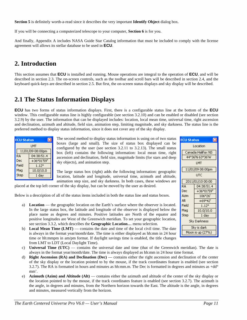
The second method to display status information is using on of two status boxes (large and small). The size of status box displayed can be configured by the user (see section 3.2.11 to 3.2.13). The small status box (left) contains the following information: local mean time, right ascension and declination, field size, magnitude limits (for stars and deep sky objects), and animation step. The large status box (right) adds the following information: geographic location, latitude and longitude, universal time, azimuth and altitude, animation step size, and sky darkness. In both cases, these windows are
placed at the top left corner of the sky display, but can be moved by the user as desired. Below is a description of all of the status items included in both the status line and status boxes.
a) Location — the geographic location on the Earth’s surface where the observer is located. In the large status box, the latitude and longitude of the observer is displayed below the place name as degrees and minutes. Positive latitudes are North of the equator and positive longitudes are West of the Greenwich meridian. To set your geographic location, see section 3.3.2, which describes the Geographic Location… menu selection.
b) Local Mean Time (LMT) — contains the date and time of the local civil time. The date is always in the format year/month/date. The time is either displayed as hh:mm in 24 hour time or hh:mmpm in am/pm format. If daylight savings time is enabled, the title changes from LMT to LDT (Local Daylight Time).
c) Universal Time (UTC) — contains the universal date and time (that of the Greenwich meridian). The date is always in the format year/month/date. The time is always displayed as hh:mm in 24 hour time format.
d) Right Ascension (RA) and Declination (Dec) — contains either the right ascension and declination of the center of the sky display or the location pointed to by the mouse, if the track coordinates feature is enabled (see section 3.2.7). The RA is formatted in hours and minutes as hh:mm.m. The Dec is formatted in degrees and minutes as +dd° mm’.
e) Azimuth (Azim) and Altitude (Alt) — contains either the azimuth and altitude of the center of the sky display or the location pointed to by the mouse, if the track coordinates feature is enabled (see section 3.2.7). The azimuth is the angle, in degrees and minutes, from the Northern horizon towards the East. The altitude is the angle, in degrees and minutes, measured vertically from the horizon.
The Earth Centered Universe Pro V6.0 — User’s Manual Page 12
f) Field Size (Field) — contains the number of vertical degrees currently shown by the sky display. The minimum field size is 0.1 degrees and the maximum is 180 degrees.
g) Animation Time Step (Step) — contains the value of the time step used by the animation mode in minutes, hours, days, months, or years. In the large status box, if an arbitrary time step has been entered, the word “Manual” may be shown instead of the actual value.
h) Magnitude (Mag) — contains the faintest magnitude that stars, deep sky objects, variable stars, and double stars are displayed in the sky display. These numbers are usually the same as that set in the Magnitude Limits... menu selection, however to keep the sky drawing speed fast, the faintest magnitude for stars automatically changes with the field size; this item always displays the actual magnitude limits currently in effect. See section 3.4.3, which describes the Magnitude Limits… menu selection.
i) Sky Darkness — contains information about sky darkness influenced by the Sun and the Moon. By the Sun: “Daylight” means the Sun is above the horizon “Sun is down” means the Sun is below the horizon (between sunset and civil twilight “>Civil Twilight” means the sky darkness is between civil and nautical twilight “>Nautical Twilight” means the sky darkness is between nautical and astronomical twilight “Sky is dark” means the sky darkness has reached astronomical twilight By the Moon: “Moon is up” means that the Moon is above the horizon – also displayed is the phase of the
Moon as the percent of illumination. “Moon is down” means the Moon is below the horizon.
j) Local Sidereal Time (LST) — contains the current local sidereal time (this is the right ascension of objects presently crossing the meridian).
2.2 The Sky Display Most of ECU’s main window is occupied by the sky display. There are three “chart modes” used to draw the sky. These are the Star Atlas mode, the Local Horizon mode, and the Manual Sky Rotation mode. The Star Atlas mode depicts the sky similarly to conventional printed star charts — that is, with the lines of declination horizontal, lines of right ascension vertical, and north up. The Local Horizon mode depicts the sky as it would appear relative to the Earth’s horizon from the current geographic location — that is, “up” in the sky is “up” on the screen. To select the mode desired, see section 3.4.1. The Local Horizon mode provides a more accurate simulation of the sky, the only penalty is that it draws a bit slower than the Star Atlas mode. This reduction is speed will only be noticeable when using very slow computers by today’s standards. The Manual Sky Rotation mode is used to rotate the chart to any arbitrary angle as specified by the user. The angle used is with respect to the Sky Atlas mode. For example, 0 degrees of manual rotation would produce the same result as the Sky Atlas mode. The sky display shows the positions of celestial objects using one of three “projections”. These three projections were selected for the speed of their calculation, however there is some distortion at the limits of their usefulness. In the Star Atlas mode when displaying the sky from -45 to +45 degrees Declination and a field size of 60 degrees or less, a simple modified-Mercator projection is used. This projection causes the objects at high Declinations to be distorted (spread-out), most noticeable in constellations like Ursa Major (the big dipper). This is the same distortion that makes Canada appear much larger than the United States on world maps with similar projections (Canada is only about 10% larger). In the Star Atlas mode when displaying the sky either North of +45 or South of -45 degrees in Declination and a field size of 60 degrees or less, the Zenithal Equidistant Projection is used. This projection is quite good, but does spread out objects a bit at low Declinations. When displaying the sky with field sizes larger than 60 degrees in the Star Atlas mode or at all times in the Local Horizon mode, an Orthogonal Projection is used. This projection is essentially a sphere (like the Earth) viewed from infinity. It can show an entire hemisphere of the sky at once, but suffers from distortion at the edges of the field. The objects and items displayed in the sky display are listed below. Each will be discussed in detail in sections 3 and 2.4 by the specific menu selection or screen resource that controls their operation.
The Earth Centered Universe Pro V6.0 — User’s Manual Page 13
a) Grid — the equatorial (aligned to right ascension and declination) or local horizon (aligned to azimuth and altitude)
coordinate grids help illustrate the sky projections just described. The grid is automatically scaled so that a sufficient number of lines always cross the screen.
b) Stars — stars are displayed as varying sized dots according to the star’s brightness. The larger the dot, the brighter is the star.
c) Lines — there are many lines displayed by ECU. These include the constellation lines, constellation boundary lines, horizon line, ecliptic line, meridian line, galactic equator line and telescope field of view lines. Markers are also displayed at the Zenith (the overhead point), the North and South poles, and the North and South galactic poles.
d) Labels — there are text labels displayed for solar system objects, constellation names, and labels for the coordinate grid, ecliptic and horizon lines, and markers. There are extensive options for labeling stars and deep sky and other objects. The fonts for all labels are programmable by the user.
e) Solar System objects — the planets, sun, anti-sun, moon, comets and asteroids are displayed. The Sun and Moon are displayed to their correct size. The phase of the Moon is also shown. Planets are displayed as a small point (similar in size to a medium brightness star, except with a unique color). Comets are displayed using the special symbol below, which resembles a comet. If a comet tail length is specified, its projected length is shown on the sky by a line.
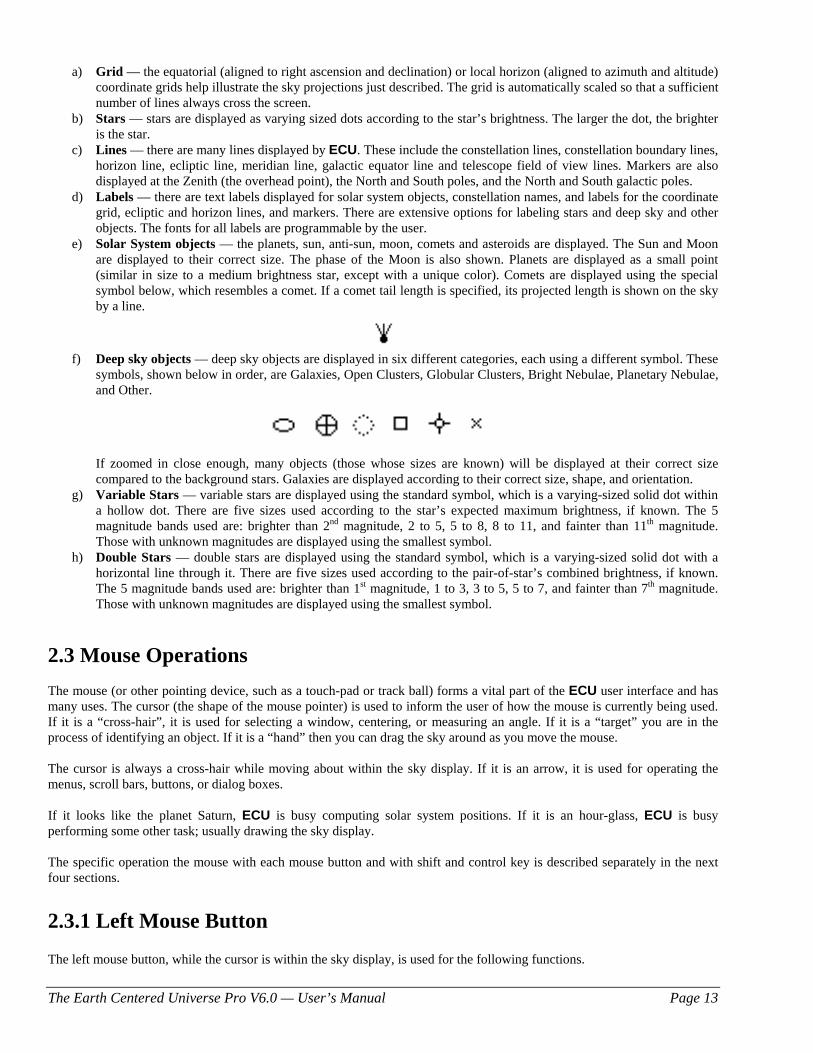
f) Deep sky objects — deep sky objects are displayed in six different categories, each using a different symbol. These
symbols, shown below in order, are Galaxies, Open Clusters, Globular Clusters, Bright Nebulae, Planetary Nebulae, and Other.
If zoomed in close enough, many objects (those whose sizes are known) will be displayed at their correct size
compared to the background stars. Galaxies are displayed according to their correct size, shape, and orientation. g) Variable Stars — variable stars are displayed using the standard symbol, which is a varying-sized solid dot within
a hollow dot. There are five sizes used according to the star’s expected maximum brightness, if known. The 5 magnitude bands used are: brighter than 2nd magnitude, 2 to 5, 5 to 8, 8 to 11, and fainter than 11th magnitude. Those with unknown magnitudes are displayed using the smallest symbol.
h) Double Stars — double stars are displayed using the standard symbol, which is a varying-sized solid dot with a horizontal line through it. There are five sizes used according to the pair-of-star’s combined brightness, if known. The 5 magnitude bands used are: brighter than 1st magnitude, 1 to 3, 3 to 5, 5 to 7, and fainter than 7th magnitude. Those with unknown magnitudes are displayed using the smallest symbol.
2.3 Mouse Operations The mouse (or other pointing device, such as a touch-pad or track ball) forms a vital part of the ECU user interface and has many uses. The cursor (the shape of the mouse pointer) is used to inform the user of how the mouse is currently being used. If it is a “cross-hair”, it is used for selecting a window, centering, or measuring an angle. If it is a “target” you are in the process of identifying an object. If it is a “hand” then you can drag the sky around as you move the mouse. The cursor is always a cross-hair while moving about within the sky display. If it is an arrow, it is used for operating the menus, scroll bars, buttons, or dialog boxes. If it looks like the planet Saturn, ECU is busy computing solar system positions. If it is an hour-glass, ECU is busy performing some other task; usually drawing the sky display. The specific operation the mouse with each mouse button and with shift and control key is described separately in the next four sections.
2.3.1 Left Mouse Button The left mouse button, while the cursor is within the sky display, is used for the following functions.
The Earth Centered Universe Pro V6.0 — User’s Manual Page 14
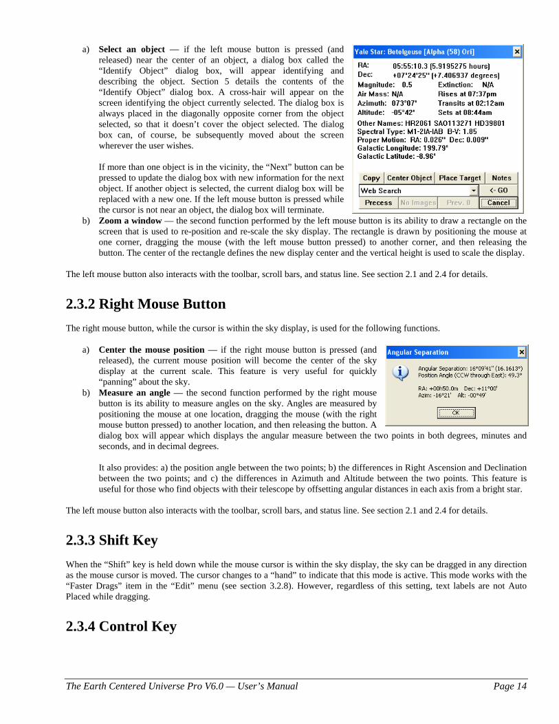
a) Select an object — if the left mouse button is pressed (and
released) near the center of an object, a dialog box called the “Identify Object” dialog box, will appear identifying and describing the object. Section 5 details the contents of the “Identify Object” dialog box. A cross-hair will appear on the screen identifying the object currently selected. The dialog box is always placed in the diagonally opposite corner from the object selected, so that it doesn’t cover the object selected. The dialog box can, of course, be subsequently moved about the screen wherever the user wishes.
If more than one object is in the vicinity, the “Next” button can be
pressed to update the dialog box with new information for the next object. If another object is selected, the current dialog box will be replaced with a new one. If the left mouse button is pressed while the cursor is not near an object, the dialog box will terminate.
b) Zoom a window — the second function performed by the left mouse button is its ability to draw a rectangle on the screen that is used to re-position and re-scale the sky display. The rectangle is drawn by positioning the mouse at one corner, dragging the mouse (with the left mouse button pressed) to another corner, and then releasing the button. The center of the rectangle defines the new display center and the vertical height is used to scale the display.
The left mouse button also interacts with the toolbar, scroll bars, and status line. See section 2.1 and 2.4 for details.
2.3.2 Right Mouse Button The right mouse button, while the cursor is within the sky display, is used for the following functions.
a) Center the mouse position — if the right mouse button is pressed (and released), the current mouse position will become the center of the sky display at the current scale. This feature is very useful for quickly “panning” about the sky.
b) Measure an angle — the second function performed by the right mouse button is its ability to measure angles on the sky. Angles are measured by positioning the mouse at one location, dragging the mouse (with the right mouse button pressed) to another location, and then releasing the button. A dialog box will appear which displays the angular measure between the two points in both degrees, minutes and seconds, and in decimal degrees.
It also provides: a) the position angle between the two points; b) the differences in Right Ascension and Declination between the two points; and c) the differences in Azimuth and Altitude between the two points. This feature is useful for those who find objects with their telescope by offsetting angular distances in each axis from a bright star.
The left mouse button also interacts with the toolbar, scroll bars, and status line. See section 2.1 and 2.4 for details.
2.3.3 Shift Key When the “Shift” key is held down while the mouse cursor is within the sky display, the sky can be dragged in any direction as the mouse cursor is moved. The cursor changes to a “hand” to indicate that this mode is active. This mode works with the “Faster Drags” item in the “Edit” menu (see section 3.2.8). However, regardless of this setting, text labels are not Auto Placed while dragging.
2.3.4 Control Key
The Earth Centered Universe Pro V6.0 — User’s Manual Page 15
When the “control” (Ctrl) key is held down while the mouse cursor is within the sky display, the coordinate displays in the status box and/or status line update as the mouse cursor is moved. This mode works with the “Track Coordinates” item in the “Edit” menu (see section 3.2.7).
2.4 On-Screen Controls The on-screen controls include the scroll bars, toolbar, and speed buttons. Each is described below:
a) Scroll Bars — Two scroll bars are used to rapidly move the center of the sky display about the celestial sphere. The scroll bars can be enabled or disabled using the menu selection described in section 3.2.5. They are used in two modes as controlled by the menu selection described in section 3.2.6.
1) RA/Dec — The vertical bar is used to change the Declination. +90 degrees is at the top; -90 degrees is at the bottom. Pressing the end arrows will move the pointer (and the sky display) by one degree and pressing along the bar will move the pointer by 10 degrees. The horizontal bar is used to change the Right Ascension. 23 hours 59 minutes is at the left; 0 hours is at the right. Pressing the end arrows will move the pointer by 4 minutes and pressing along the bar will move the pointer by one hour. When sliding the scroll bars by dragging the pointer, observe at the Right Ascension and Declination displays to know when to stop.
2) Azim/Alt — The vertical bar is used to change the Altitude with reference to the local horizon. +90 degrees is at the top (the Zenith); -90 degrees is at the bottom (the Nadir). Pressing the end arrows will move the pointer (and the sky display) by one degree and pressing along the bar will move the pointer by 10 degrees. The horizontal bar is used to change the Azimuth with reference to the local horizon. 0 degrees (North) is at the left; 358.5 degrees is at the right. Pressing the end arrows will move the pointer by 1.5 degrees and pressing along the bar will move the pointer by 15 degrees. When sliding the scroll bars by dragging the pointer, observe at the Azimuth and Altitude displays to know when to stop.
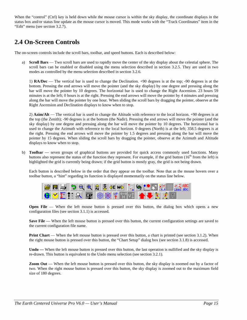
b) Toolbar — seven groups of graphical buttons are provided for quick access commonly used functions. Many buttons also represent the status of the function they represent. For example, if the grid button (16th from the left) is highlighted the grid is currently being drawn; if the grid button is mostly gray, the grid is not being drawn.
Each button is described below in the order that they appear on the toolbar. Note that as the mouse hovers over a toolbar button, a “hint” regarding its function is displayed momentarily on the status line below.
Open File — When the left mouse button is pressed over this button, the dialog box which opens a new
configuration files (see section 3.1.1) is accessed.
Save File — When the left mouse button is pressed over this button, the current configuration settings are saved to the current configuration file name.
Print Chart — When the left mouse button is pressed over this button, a chart is printed (see section 3.1.2). When the right mouse button is pressed over this button, the “Chart Setup” dialog box (see section 3.1.8) is accessed.
Undo — When the left mouse button is pressed over this button, the last operation is nullified and the sky display is
re-drawn. This button is equivalent to the Undo menu selection (see section 3.2.1). Zoom Out — When the left mouse button is pressed over this button, the sky display is zoomed out by a factor of two. When the right mouse button is pressed over this button, the sky display is zoomed out to the maximum field size of 180 degrees.
The Earth Centered Universe Pro V6.0 — User’s Manual Page 16
Zoom In — When the left mouse button is pressed over this button, the sky display is zoomed in by a factor of two. When the right mouse button is pressed over this button, the sky display is zoomed in to the minimum field size of 0.1 degrees.
North — When the left mouse button is pressed over this button, the sky display is centered at the northern horizon.
When the right mouse button is pressed over this button, the sky display is re-centered 10 degrees to the north. South — When the left mouse button is pressed over this button, the sky display is centered at the southern horizon.
When the right mouse button is pressed over this button, the sky display is re-centered 10 degrees to the south. East — When the left mouse button is pressed over this button, the sky display is centered at the eastern horizon.
When the right mouse button is pressed over this button, the sky display is re-centered 10 hour to the east. West — When the left mouse button is pressed over this button, the sky display is centered at the western horizon.
When the right mouse button is pressed over this button, the sky display is re-centered 1 hour to the west. Stars — When the left mouse button is pressed over this button, the display of stars is “toggled” on or off. When
the right mouse button is pressed over this button, the dialog box controlling sky database settings (see section 3.4.4) is accessed.
Deep Sky — When the left mouse button is pressed over this button, the display of deep sky objects is “toggled” on
or off. When the right mouse button is pressed over this button, the dialog box controlling deep sky parameters (see section 3.4.4) is accessed.
Variable Stars — When the left mouse button is pressed over this button, the display of variable stars is “toggled”
on or off. When the right mouse button is pressed over this button, the dialog box that sets the magnitude limits (see section 3.4.3) is accessed. Double Stars — When the left mouse button is pressed over this button, the display of variable stars is “toggled” on or off. When the right mouse button is pressed over this button, the dialog box that sets the magnitude limits (see section 3.4.3) is accessed.
Solar System — When the left mouse button is pressed over this button, the display of solar system objects is
“toggled” on or off. When the right mouse button is pressed over this button, the dialog box controlling the planets (see section 3.4.8) is accessed.
Grid — When the left mouse button is pressed over this button, the display of the coordinate grid cycles through
showing the equatorial (aligned to right ascension and declination), the local horizon (aligned to azimuth and altitude) grid, and turning off the grid altogether. When the the right mouse button is pressed over this button, the dialog box controlling Custom Horizons (see section 3.4.12) is accessed.
Lines — When the left mouse button is pressed over this button, the display of lines and points is “toggled” on or
off. When the right mouse button is pressed over this button, the dialog box controlling the display of lines and points (see section 3.4.13) is accessed.
Labels — When the left mouse button is pressed over this button, the display of labels is “toggled” on or off. When
the right mouse button is pressed over this button, the dialog box controlling label settings (see section 3.4.12) is accessed.
Geographic Location — When the left mouse button is pressed over this button, the dialog box that sets the
geographic location on the Earth (see section 3.3.2) is accessed. When the right mouse button is pressed over this button “Sync Location or Time from GPS” dialog box (see section 3.3.3) is accessed.
Time — When the left mouse button is pressed over this button, the dialog box that sets the local time (see section
3.1.1.1) is accessed. When the right mouse button is pressed over this button, the dialog box that sets the Universal time (see section 3.1.1.2) is accessed.
The Earth Centered Universe Pro V6.0 — User’s Manual Page 17
Field Size — When the left mouse button is pressed over this button, the dialog box that sets the vertical field size (see section 3.4.16) is accessed.
Magnitude Limits — When the left mouse button is pressed over this button, the dialog box that sets the
magnitude limits (see section 3.4.3) is accessed. When the right mouse button is pressed over this button, the dialog box controlling sky database settings (see section 3.4.4) is accessed.
Database Search — When the left mouse button is pressed over this button, the dialog box which sets searches for
an object in the ECU databases (see section 3.6.1) is accessed. When the right mouse button is pressed over this button, the Object List dialog box (see section 3.6.10) is accessed.
Enable/Disable Telescope Interface — When the left mouse button is pressed over this button, the operation of ECU’s telescope interface is “toggled” on and off. When the right mouse button is pressed over this button, the “Telescope Type and General Settings” dialog box (see section 3.8.15) is accessed. Place Target — When the left mouse button is pressed over this button, a Field Target is placed at the center of the sky display (see section 3.4.18.3). When the right mouse button is pressed over this button, the dialog box that controls the default field target parameters (see section 3.4.18.1) is accessed.
Clear Target — When the left mouse button is pressed over this button, the last Field Target placed is cleared.
Chart Mode —When the left mouse button is pressed over this button, the sky display mode is cycled between Sky Atlas, Local Horizon, and Manual Sky Rotation modes (see Section 3.4.1). The icon displayed indicates the current mode — “UP” means Local Horizon mode, ”N” means Sky Atlas mode, and “?” means Manual Sky Rotation mode.
Flip Horizontal —When the left mouse button is pressed over this button, the sky display is “toggled” between no horizontal flip and horizontal flip (see Section 3.4.15). Flip Vertical —When the left mouse button is pressed over this button, the sky display is “toggled” between no vertical flip and vertical flip (see Section 3.4.15).
Increase Time Step — When the left mouse button is pressed over this button, the animation time step in increased
by one step. When the right mouse button is pressed over this button, the dialog box that sets a manual animation time step (see section 3.6.15.1) is accessed.
Decrease Time Step — When the left mouse button is pressed over this button, the animation time step in decreased by one step. When the right mouse button is pressed over this button, the dialog box that sets a manual animation time step (see section 3.6.15.1) is accessed.
Reverse One Step — When the left mouse button is pressed over this button, ECU’s time is stepped backward by one animation time step in increased by one step. When the right mouse button is pressed over this button the “Center on Previous Object” function (see section 3.6.11) is activated.
Forward One Step — When the left mouse button is pressed over this button, ECU’s time is stepped forward by one animation time step in increased by one step. When the right mouse button is pressed over this button the “Center on Next Object” function (see section 3.6.10) is activated.
Animation Start/Stop — When the left mouse button is pressed over this button, the operation of the animation mode is “toggled” on and off.
There are two special mouse operations that relate to the toolbar. If the left mouse button is pressed in an unused
region of the toolbar, the state of the status box is cycled through being disabled, small in size, and large in size. If the right mouse button is pressed in an unused region of toolbar, the status line is “toggled” on and off.
c) Status Line Speed buttons — When the left mouse button is pressed while over the boxes on the status line used to
display various status items (see section 2.1), the appropriate dialog box which relates to the items is accessed. For
The Earth Centered Universe Pro V6.0 — User’s Manual Page 18
example, if the left mouse button is pressed within the box that displays the magnitude limits, the “Magnitude Limits...” dialog box will pop-up.
In addition, pressing the right mouse button over:
- the geographic location display causes the “Sync Location or Time from GPS” dialog box (see section 3.3.3) to be accessed
- the local or UTC time display causes the “Julian Date/Sidereal Time” dialog box (see section 3.8.2) to be accessed
- the animation step size display causes the animation step size to toggle back and forth between the last two step sizes
There are two special mouse operations that relate to the status line. If the left mouse button is pressed in an unused
region of the status line, the dialog box that controls the status line is accessed. If the right mouse button is pressed in an unused region of the status line, the toolbar is “toggled” on and off.
Note that as the mouse hovers over the status line, a “hint” regarding the button’s function is displayed on the far right of the status line.
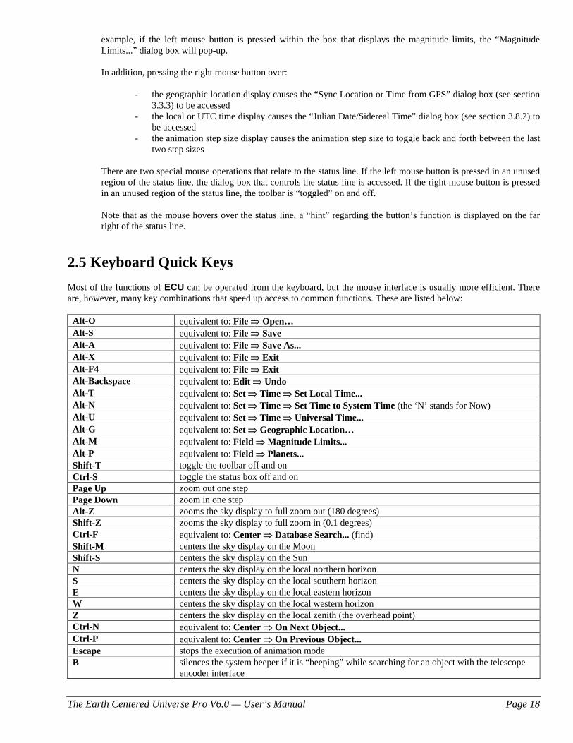
2.5 Keyboard Quick Keys Most of the functions of ECU can be operated from the keyboard, but the mouse interface is usually more efficient. There are, however, many key combinations that speed up access to common functions. These are listed below:
Alt-O equivalent to: File ⇒ Open… Alt-S equivalent to: File ⇒ Save Alt-A equivalent to: File ⇒ Save As... Alt-X equivalent to: File ⇒ Exit Alt-F4 equivalent to: File ⇒ Exit Alt-Backspace equivalent to: Edit ⇒ Undo Alt-T equivalent to: Set ⇒ Time ⇒ Set Local Time... Alt-N equivalent to: Set ⇒ Time ⇒ Set Time to System Time (the ‘N’ stands for Now) Alt-U equivalent to: Set ⇒ Time ⇒ Universal Time... Alt-G equivalent to: Set ⇒ Geographic Location… Alt-M equivalent to: Field ⇒ Magnitude Limits... Alt-P equivalent to: Field ⇒ Planets... Shift-T toggle the toolbar off and on Ctrl-S toggle the status box off and on Page Up zoom out one step Page Down zoom in one step Alt-Z zooms the sky display to full zoom out (180 degrees) Shift-Z zooms the sky display to full zoom in (0.1 degrees) Ctrl-F equivalent to: Center ⇒ Database Search... (find) Shift-M centers the sky display on the Moon Shift-S centers the sky display on the Sun N centers the sky display on the local northern horizon S centers the sky display on the local southern horizon E centers the sky display on the local eastern horizon W centers the sky display on the local western horizon Z centers the sky display on the local zenith (the overhead point) Ctrl-N equivalent to: Center ⇒ On Next Object... Ctrl-P equivalent to: Center ⇒ On Previous Object... Escape stops the execution of animation mode B silences the system beeper if it is “beeping” while searching for an object with the telescope
encoder interface
The Earth Centered Universe Pro V6.0 — User’s Manual Page 19
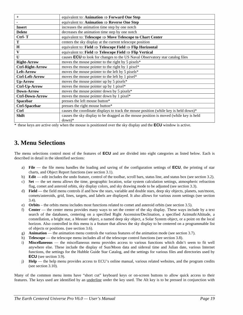
+ equivalent to: Animation ⇒ Forward One Step - equivalent to: Animation ⇒ Reverse One Step Insert increases the animation time step by one notch Delete decreases the animation time step by one notch Ctrl- T equivalent to: Telescope ⇒ Move Telescope to Chart Center T centers the sky display at the current telescope position H equivalent to: Field ⇒ Telescope Field ⇒ Flip Horizontal V equivalent to: Field ⇒ Telescope Field ⇒ Flip Vertical U causes ECU to look for changes to the US Naval Observatory star catalog files Right-Arrow moves the mouse pointer to the right by 5 pixels* Ctrl-Right-Arrow moves the mouse pointer to the right by 1 pixel* Left-Arrow moves the mouse pointer to the left by 5 pixels* Ctrl-Left-Arrow moves the mouse pointer to the left by 1 pixel* Up-Arrow moves the mouse pointer up by 5 pixels* Ctrl-Up-Arrow moves the mouse pointer up by 1 pixel* Down-Arrow moves the mouse pointer down by 5 pixels* Ctrl-Down-Arrow moves the mouse pointer down by 1 pixel* Spacebar presses the left mouse button* Ctrl-Spacebar presses the right mouse button* Ctrl causes the coordinate displays to track the mouse position (while key is held down)* Shift causes the sky display to be dragged as the mouse position is moved (while key is held
down)* * these keys are active only when the mouse is positioned over the sky display and the ECU window is active.
3. Menu Selections The menu selections control most of the features of ECU and are divided into eight categories as listed below. Each is described in detail in the identified sections:
a) File — the file menu handles the loading and saving of the configuration settings of ECU, the printing of star charts, and Object Report functions (see section 3.1).
b) Edit — edit includes the undo feature, control of the toolbar, scroll bars, status line, and status box (see section 3.2). c) Set — the set menu allows the time, geographic location, solar system calculation settings, atmospheric refraction
flag, comet and asteroid orbits, sky display colors, and sky drawing mode to be adjusted (see section 3.3). d) Field — the field menu controls if and how the stars, variable and double stars, deep sky objects, planets, sun/moon,
comets/asteroids, grid, lines, targets, and labels are displayed. It also allows for various zoom settings (see section 3.4).
e) Orbits – the orbits menu includes most functions related to comet and asteroid orbits (see section 3.5). f) Center — the center menu provides many ways to set the center of the sky display. These ways include by a text
search of the databases, centering on a specified Right Ascension/Declination, a specified Azimuth/Altitude, a constellation, a bright star, a Messier object, a named deep sky object, a Solar System object, or a point on the local horizon. Also controlled in this menu is a feature that allows the sky display to be centered on a programmable list of objects or positions. (see section 3.6).
g) Animation — the animation menu controls the various features of the animation mode (see section 3.7). h) Telescope — the telescope menu includes all of the telescope control functions (see section 3.8). i) Miscellaneous — the miscellaneous menu provides access to various functions which didn’t seem to fit well
anywhere else. These include the display of Sun/Moon data and sidereal time and Julian date, various Internet functions, the settings for the Hubble Guide Star Catalog, and the settings for various files and directories used by ECU (see section 3.9).
j) Help — the help menu provides access to ECU’s online manual, various related websites, and the program credits (see section 3.10).
Many of the common menu items have “short cut” keyboard keys or on-screen buttons to allow quick access to their features. The keys used are identified by an underline under the key used. The Alt key is to be pressed in conjunction with
The Earth Centered Universe Pro V6.0 — User’s Manual Page 20
the identified key. Also, some menu items identify their keyboard equivalent to the right in their menu item. For others, see section 2.5.
3.1 File Menu The File menu allows the configuration settings of ECU to be loaded (opened) and saved. Virtually every setting in ECU is stored in the configuration file. This allows ECU to be “set up” for a particular astronomical event and this event saved to a unique configuration file for quick retrieval later. The file menu also provides access to the setup of and printing of high-quality star charts of the current sky display and the ability to configure and generate Object Reports.
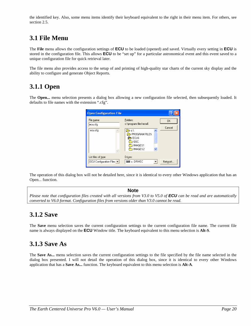
3.1.1 Open The Open... menu selection presents a dialog box allowing a new configuration file selected, then subsequently loaded. It defaults to file names with the extension “.cfg”.
The operation of this dialog box will not be detailed here, since it is identical to every other Windows application that has an Open... function.
Note Please note that configuration files created with all versions from V3.0 to V5.0 of ECU can be read and are automatically converted to V6.0 format. Configuration files from versions older than V3.0 cannot be read.
3.1.2 Save The Save menu selection saves the current configuration settings to the current configuration file name. The current file name is always displayed on the ECU Window title. The keyboard equivalent to this menu selection is Alt-S.
3.1.3 Save As
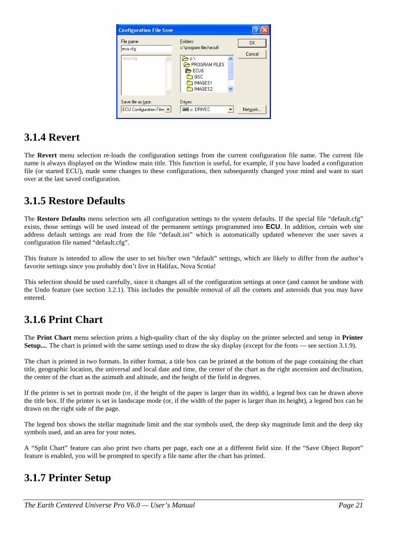
The Save As... menu selection saves the current configuration settings to the file specified by the file name selected in the dialog box presented. I will not detail the operation of this dialog box, since it is identical to every other Windows application that has a Save As... function. The keyboard equivalent to this menu selection is Alt-A.
The Earth Centered Universe Pro V6.0 — User’s Manual Page 21
3.1.4 Revert The Revert menu selection re-loads the configuration settings from the current configuration file name. The current file name is always displayed on the Window main title. This function is useful, for example, if you have loaded a configuration file (or started ECU), made some changes to these configurations, then subsequently changed your mind and want to start over at the last saved configuration.
3.1.5 Restore Defaults The Restore Defaults menu selection sets all configuration settings to the system defaults. If the special file “default.cfg” exists, those settings will be used instead of the permanent settings programmed into ECU. In addition, certain web site address default settings are read from the file “default.ini” which is automatically updated whenever the user saves a configuration file named “default.cfg”. This feature is intended to allow the user to set his/her own “default” settings, which are likely to differ from the author’s favorite settings since you probably don’t live in Halifax, Nova Scotia! This selection should be used carefully, since it changes all of the configuration settings at once (and cannot be undone with the Undo feature (see section 3.2.1). This includes the possible removal of all the comets and asteroids that you may have entered.
3.1.6 Print Chart The Print Chart menu selection prints a high-quality chart of the sky display on the printer selected and setup in Printer Setup.... The chart is printed with the same settings used to draw the sky display (except for the fonts — see section 3.1.9). The chart is printed in two formats. In either format, a title box can be printed at the bottom of the page containing the chart title, geographic location, the universal and local date and time, the center of the chart as the right ascension and declination, the center of the chart as the azimuth and altitude, and the height of the field in degrees. If the printer is set in portrait mode (or, if the height of the paper is larger than its width), a legend box can be drawn above the title box. If the printer is set in landscape mode (or, if the width of the paper is larger than its height), a legend box can be drawn on the right side of the page. The legend box shows the stellar magnitude limit and the star symbols used, the deep sky magnitude limit and the deep sky symbols used, and an area for your notes. A “Split Chart” feature can also print two charts per page, each one at a different field size. If the “Save Object Report” feature is enabled, you will be prompted to specify a file name after the chart has printed.
3.1.7 Printer Setup
The Earth Centered Universe Pro V6.0 — User’s Manual Page 22
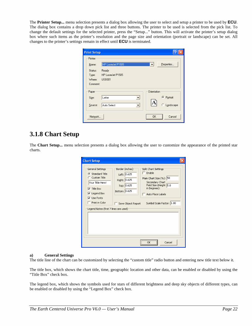
The Printer Setup... menu selection presents a dialog box allowing the user to select and setup a printer to be used by ECU. The dialog box contains a drop down pick list and three buttons. The printer to be used is selected from the pick list. To change the default settings for the selected printer, press the “Setup...” button. This will activate the printer’s setup dialog box where such items as the printer’s resolution and the page size and orientation (portrait or landscape) can be set. All changes to the printer’s settings remain in effect until ECU is terminated.
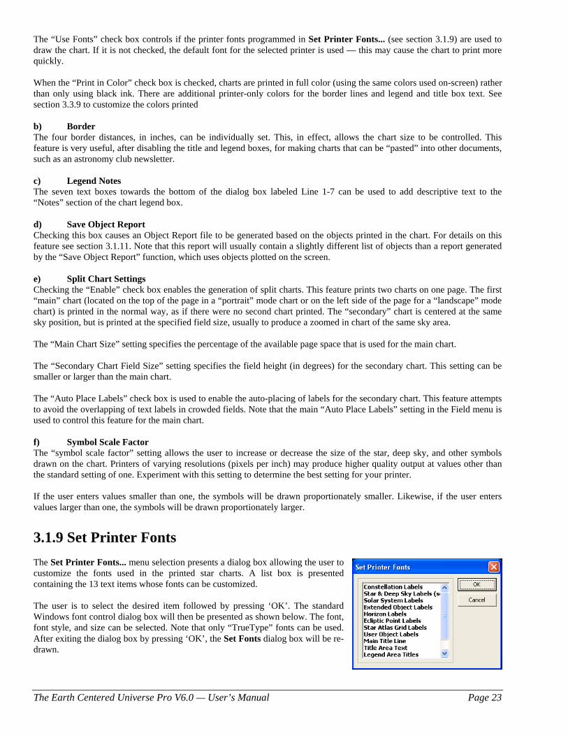
3.1.8 Chart Setup The Chart Setup... menu selection presents a dialog box allowing the user to customize the appearance of the printed star charts.
a) General Settings The title line of the chart can be customized by selecting the “custom title” radio button and entering new title text below it. The title box, which shows the chart title, time, geographic location and other data, can be enabled or disabled by using the “Title Box” check box. The legend box, which shows the symbols used for stars of different brightness and deep sky objects of different types, can be enabled or disabled by using the “Legend Box” check box.
The Earth Centered Universe Pro V6.0 — User’s Manual Page 23
The “Use Fonts” check box controls if the printer fonts programmed in Set Printer Fonts... (see section 3.1.9) are used to draw the chart. If it is not checked, the default font for the selected printer is used — this may cause the chart to print more quickly. When the “Print in Color” check box is checked, charts are printed in full color (using the same colors used on-screen) rather than only using black ink. There are additional printer-only colors for the border lines and legend and title box text. See section 3.3.9 to customize the colors printed b) Border The four border distances, in inches, can be individually set. This, in effect, allows the chart size to be controlled. This feature is very useful, after disabling the title and legend boxes, for making charts that can be “pasted” into other documents, such as an astronomy club newsletter. c) Legend Notes The seven text boxes towards the bottom of the dialog box labeled Line 1-7 can be used to add descriptive text to the “Notes” section of the chart legend box. d) Save Object Report Checking this box causes an Object Report file to be generated based on the objects printed in the chart. For details on this feature see section 3.1.11. Note that this report will usually contain a slightly different list of objects than a report generated by the “Save Object Report” function, which uses objects plotted on the screen. e) Split Chart Settings Checking the “Enable” check box enables the generation of split charts. This feature prints two charts on one page. The first “main” chart (located on the top of the page in a “portrait” mode chart or on the left side of the page for a “landscape” mode chart) is printed in the normal way, as if there were no second chart printed. The “secondary” chart is centered at the same sky position, but is printed at the specified field size, usually to produce a zoomed in chart of the same sky area. The “Main Chart Size” setting specifies the percentage of the available page space that is used for the main chart. The “Secondary Chart Field Size” setting specifies the field height (in degrees) for the secondary chart. This setting can be smaller or larger than the main chart. The “Auto Place Labels” check box is used to enable the auto-placing of labels for the secondary chart. This feature attempts to avoid the overlapping of text labels in crowded fields. Note that the main “Auto Place Labels” setting in the Field menu is used to control this feature for the main chart. f) Symbol Scale Factor The “symbol scale factor” setting allows the user to increase or decrease the size of the star, deep sky, and other symbols drawn on the chart. Printers of varying resolutions (pixels per inch) may produce higher quality output at values other than the standard setting of one. Experiment with this setting to determine the best setting for your printer. If the user enters values smaller than one, the symbols will be drawn proportionately smaller. Likewise, if the user enters values larger than one, the symbols will be drawn proportionately larger.
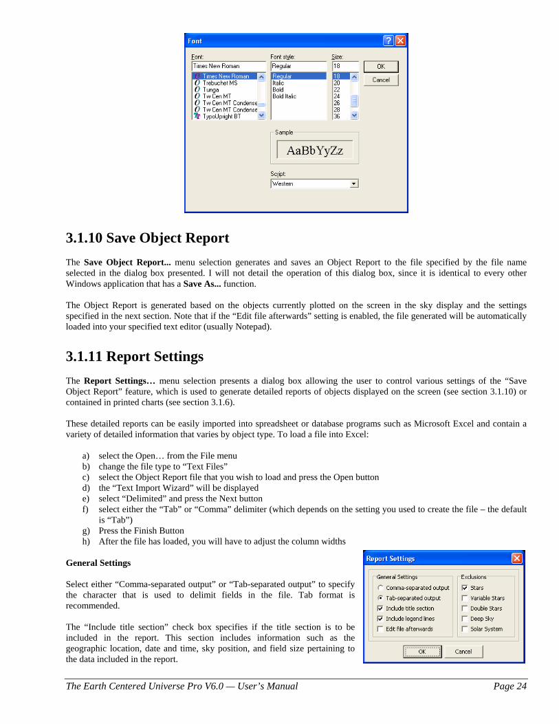
3.1.9 Set Printer Fonts The Set Printer Fonts... menu selection presents a dialog box allowing the user to customize the fonts used in the printed star charts. A list box is presented containing the 13 text items whose fonts can be customized. The user is to select the desired item followed by pressing ‘OK’. The standard Windows font control dialog box will then be presented as shown below. The font, font style, and size can be selected. Note that only “TrueType” fonts can be used. After exiting the dialog box by pressing ‘OK’, the Set Fonts dialog box will be re-drawn.
The Earth Centered Universe Pro V6.0 — User’s Manual Page 24
3.1.10 Save Object Report The Save Object Report... menu selection generates and saves an Object Report to the file specified by the file name selected in the dialog box presented. I will not detail the operation of this dialog box, since it is identical to every other Windows application that has a Save As... function. The Object Report is generated based on the objects currently plotted on the screen in the sky display and the settings specified in the next section. Note that if the “Edit file afterwards” setting is enabled, the file generated will be automatically loaded into your specified text editor (usually Notepad).
3.1.11 Report Settings The Report Settings… menu selection presents a dialog box allowing the user to control various settings of the “Save Object Report” feature, which is used to generate detailed reports of objects displayed on the screen (see section 3.1.10) or contained in printed charts (see section 3.1.6). These detailed reports can be easily imported into spreadsheet or database programs such as Microsoft Excel and contain a variety of detailed information that varies by object type. To load a file into Excel:
a) select the Open… from the File menu b) change the file type to “Text Files” c) select the Object Report file that you wish to load and press the Open button d) the “Text Import Wizard” will be displayed e) select “Delimited” and press the Next button f) select either the “Tab” or “Comma” delimiter (which depends on the setting you used to create the file – the default
is “Tab”) g) Press the Finish Button h) After the file has loaded, you will have to adjust the column widths
General Settings Select either “Comma-separated output” or “Tab-separated output” to specify the character that is used to delimit fields in the file. Tab format is recommended. The “Include title section” check box specifies if the title section is to be included in the report. This section includes information such as the geographic location, date and time, sky position, and field size pertaining to the data included in the report.
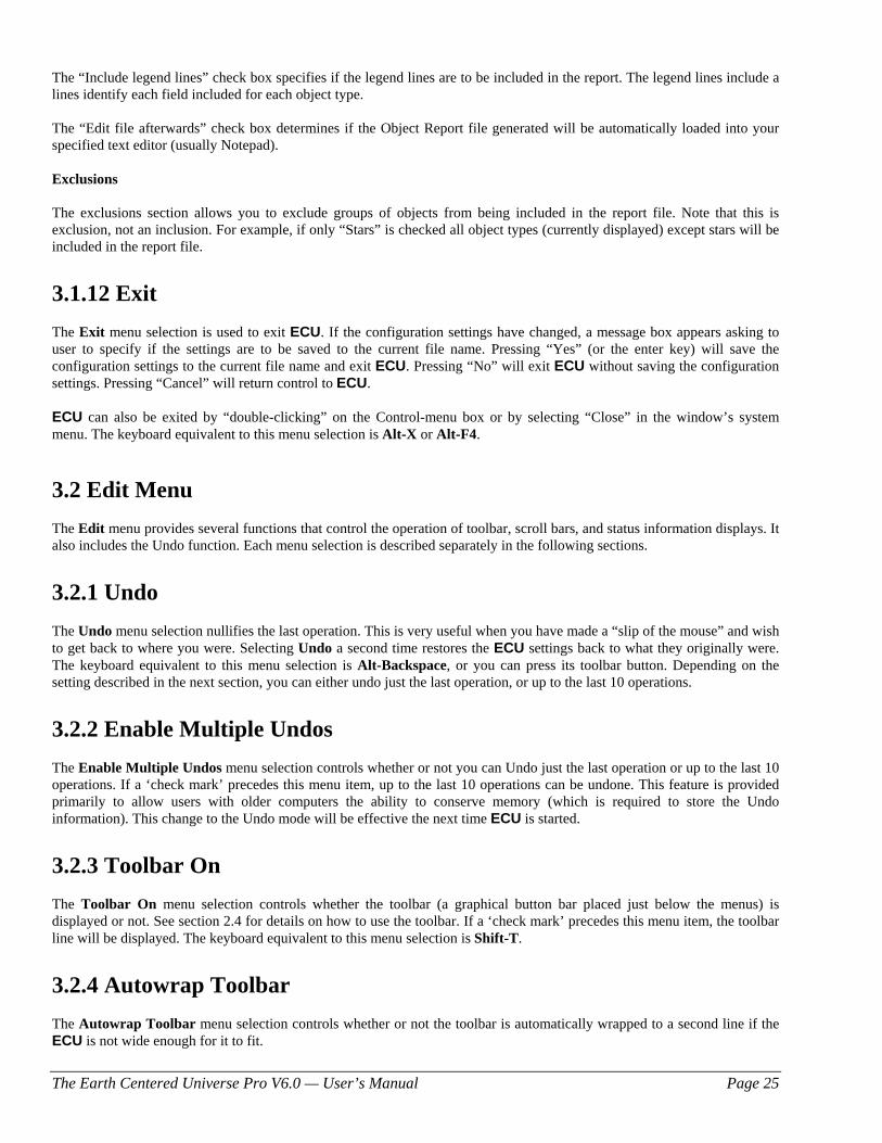
The Earth Centered Universe Pro V6.0 — User’s Manual Page 25
The “Include legend lines” check box specifies if the legend lines are to be included in the report. The legend lines include a lines identify each field included for each object type. The “Edit file afterwards” check box determines if the Object Report file generated will be automatically loaded into your specified text editor (usually Notepad). Exclusions The exclusions section allows you to exclude groups of objects from being included in the report file. Note that this is exclusion, not an inclusion. For example, if only “Stars” is checked all object types (currently displayed) except stars will be included in the report file.
3.1.12 Exit The Exit menu selection is used to exit ECU. If the configuration settings have changed, a message box appears asking to user to specify if the settings are to be saved to the current file name. Pressing “Yes” (or the enter key) will save the configuration settings to the current file name and exit ECU. Pressing “No” will exit ECU without saving the configuration settings. Pressing “Cancel” will return control to ECU. ECU can also be exited by “double-clicking” on the Control-menu box or by selecting “Close” in the window’s system menu. The keyboard equivalent to this menu selection is Alt-X or Alt-F4.
3.2 Edit Menu The Edit menu provides several functions that control the operation of toolbar, scroll bars, and status information displays. It also includes the Undo function. Each menu selection is described separately in the following sections.
3.2.1 Undo
The Undo menu selection nullifies the last operation. This is very useful when you have made a “slip of the mouse” and wish to get back to where you were. Selecting Undo a second time restores the ECU settings back to what they originally were. The keyboard equivalent to this menu selection is Alt-Backspace, or you can press its toolbar button. Depending on the setting described in the next section, you can either undo just the last operation, or up to the last 10 operations.
3.2.2 Enable Multiple Undos The Enable Multiple Undos menu selection controls whether or not you can Undo just the last operation or up to the last 10 operations. If a ‘check mark’ precedes this menu item, up to the last 10 operations can be undone. This feature is provided primarily to allow users with older computers the ability to conserve memory (which is required to store the Undo information). This change to the Undo mode will be effective the next time ECU is started.
3.2.3 Toolbar On The Toolbar On menu selection controls whether the toolbar (a graphical button bar placed just below the menus) is displayed or not. See section 2.4 for details on how to use the toolbar. If a ‘check mark’ precedes this menu item, the toolbar line will be displayed. The keyboard equivalent to this menu selection is Shift-T.
3.2.4 Autowrap Toolbar The Autowrap Toolbar menu selection controls whether or not the toolbar is automatically wrapped to a second line if the ECU is not wide enough for it to fit.
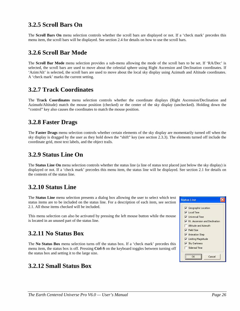
The Earth Centered Universe Pro V6.0 — User’s Manual Page 26
3.2.5 Scroll Bars On The Scroll Bars On menu selection controls whether the scroll bars are displayed or not. If a ‘check mark’ precedes this menu item, the scroll bars will be displayed. See section 2.4 for details on how to use the scroll bars.
3.2.6 Scroll Bar Mode The Scroll Bar Mode menu selection provides a sub-menu allowing the mode of the scroll bars to be set. If ‘RA/Dec’ is selected, the scroll bars are used to move about the celestial sphere using Right Ascension and Declination coordinates. If ‘Azim/Alt’ is selected, the scroll bars are used to move about the local sky display using Azimuth and Altitude coordinates. A ‘check mark’ marks the current setting.
3.2.7 Track Coordinates The Track Coordinates menu selection controls whether the coordinate displays (Right Ascension/Declination and Azimuth/Altitude) match the mouse position (checked) or the center of the sky display (unchecked). Holding down the “control” key also causes the coordinates to match the mouse position.
3.2.8 Faster Drags The Faster Drags menu selection controls whether certain elements of the sky display are momentarily turned off when the sky display is dragged by the user as they hold down the “shift” key (see section 2.3.3). The elements turned off include the coordinate grid, most text labels, and the object trails.
3.2.9 Status Line On The Status Line On menu selection controls whether the status line (a line of status text placed just below the sky display) is displayed or not. If a ‘check mark’ precedes this menu item, the status line will be displayed. See section 2.1 for details on the contents of the status line.
3.2.10 Status Line The Status Line menu selection presents a dialog box allowing the user to select which text status items are to be included on the status line. For a description of each item, see section 2.1. All those items checked will be included. This menu selection can also be activated by pressing the left mouse button while the mouse is located in an unused part of the status line.
3.2.11 No Status Box
The No Status Box menu selection turns off the status box. If a ‘check mark’ precedes this menu item, the status box is off. Pressing Ctrl-S on the keyboard toggles between turning off the status box and setting it to the large size.
3.2.12 Small Status Box
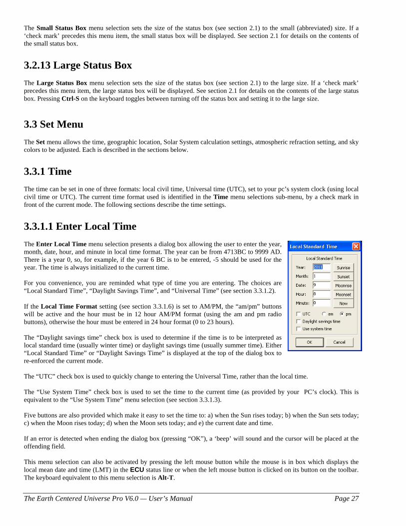
The Earth Centered Universe Pro V6.0 — User’s Manual Page 27
The Small Status Box menu selection sets the size of the status box (see section 2.1) to the small (abbreviated) size. If a ‘check mark’ precedes this menu item, the small status box will be displayed. See section 2.1 for details on the contents of the small status box.
3.2.13 Large Status Box
The Large Status Box menu selection sets the size of the status box (see section 2.1) to the large size. If a ‘check mark’ precedes this menu item, the large status box will be displayed. See section 2.1 for details on the contents of the large status box. Pressing Ctrl-S on the keyboard toggles between turning off the status box and setting it to the large size.
3.3 Set Menu The Set menu allows the time, geographic location, Solar System calculation settings, atmospheric refraction setting, and sky colors to be adjusted. Each is described in the sections below.
3.3.1 Time The time can be set in one of three formats: local civil time, Universal time (UTC), set to your pc’s system clock (using local civil time or UTC). The current time format used is identified in the Time menu selections sub-menu, by a check mark in front of the current mode. The following sections describe the time settings.
3.3.1.1 Enter Local Time The Enter Local Time menu selection presents a dialog box allowing the user to enter the year, month, date, hour, and minute in local time format. The year can be from 4713BC to 9999 AD. There is a year 0, so, for example, if the year 6 BC is to be entered, -5 should be used for the year. The time is always initialized to the current time. For you convenience, you are reminded what type of time you are entering. The choices are “Local Standard Time”, “Daylight Savings Time”, and “Universal Time” (see section 3.3.1.2). If the Local Time Format setting (see section 3.3.1.6) is set to AM/PM, the “am/pm” buttons will be active and the hour must be in 12 hour AM/PM format (using the am and pm radio buttons), otherwise the hour must be entered in 24 hour format (0 to 23 hours). The “Daylight savings time” check box is used to determine if the time is to be interpreted as local standard time (usually winter time) or daylight savings time (usually summer time). Either “Local Standard Time” or “Daylight Savings Time” is displayed at the top of the dialog box to re-enforced the current mode. The “UTC” check box is used to quickly change to entering the Universal Time, rather than the local time. The “Use System Time” check box is used to set the time to the current time (as provided by your PC’s clock). This is equivalent to the “Use System Time” menu selection (see section 3.3.1.3). Five buttons are also provided which make it easy to set the time to: a) when the Sun rises today; b) when the Sun sets today; c) when the Moon rises today; d) when the Moon sets today; and e) the current date and time. If an error is detected when ending the dialog box (pressing “OK”), a ‘beep’ will sound and the cursor will be placed at the offending field. This menu selection can also be activated by pressing the left mouse button while the mouse is in box which displays the local mean date and time (LMT) in the ECU status line or when the left mouse button is clicked on its button on the toolbar. The keyboard equivalent to this menu selection is Alt-T.
The Earth Centered Universe Pro V6.0 — User’s Manual Page 28
3.3.1.2 Enter Universal Time Entering the Universal time is accomplished identically to entering the local time, except that hour must always be entered in 24 hour format. This menu selection can also be activated by pressing the left mouse button while the mouse is in the box which displays the universal date and time (UTC) in the ECU status line or when the right mouse button is clicked on the “time” toolbar button. The keyboard equivalent to this menu selection is Alt-U.
3.3.1.3 Use System Time Selecting Use System Time causes ECU’s time to become synched to your pc’s system clock. This will also cause the sky to update automatically once per minute, therefore simulating the actual sky’s movements. See also section 3.3.1.5. After setting this mode, you might wonder why the stars are not marching by as the time changes. This is because the default behavior of ECU is to looks the center of the sky display on a specific equatorial coordinate (as opposed to a specific local horizon coordinate). This behavior can be changed – see sections 3.7.11 and 3.7.12.
3.3.1.4 Set Time to System Time Selecting Set Time to System Time causes ECU’s time to be set to your pc’s system clock. Unlike the selection Use System Time, the sky will not update automatically thereafter. The keyboard equivalent to this menu selection is Alt-N (N stands for NOW!). See also section 3.3.1.5.
3.3.1.5 PC Clock is UTC The PC Clock is UTC menu selection sets whether the computer’s clock is to be interpreted as local time or UTC. If ‘checked’, the clock should be set to UTC, if not it should be set to ‘local’ time. This setting is provided primarily for those who operate ECU in an observatory and wish their observations to be in UTC.
3.3.1.6 Local Time Format The local mean time (LMT) display in the status area is displayed in either 24 hour or am/pm format. The Local Time Format menu selection is a sub-menu of AM/PM and 24 Hour selections, each selection setting the respective format. The current format is identified by a ‘check mark’.
3.3.1.7 Daylight Savings The Daylight Savings menu selection toggles whether the current local time is to be interpreted as a daylight savings time. It is used by ECU to convert from local time to Universal time. If a ‘check mark’ is present, daylight savings mode is enabled. If ECU is using the PC’s system clock and the daylight savings time ‘check mark’ is present, the PC’s time should be set to the daylight savings time. The daylight savings mode can also be controlled from the Enter Time dialog box (see section 3.3.1.1).
3.3.2 Geographic Location The Geographic Location… menu selection presents a dialog box allowing the selection of a location on the Earth’s surface. The location can be selected from the provided list of hundreds of locations around the world or you can enter the latitude, longitude, and time zone of a location of your choice. To select a pre-programmed location, use the scroll bar controlled list box on the left side of the dialog box to bring the desired location into view and click on it with the mouse. Its place name, latitude, longitude, and time zone will be displayed on the right side of the dialog box. Press “OK” to use this location.
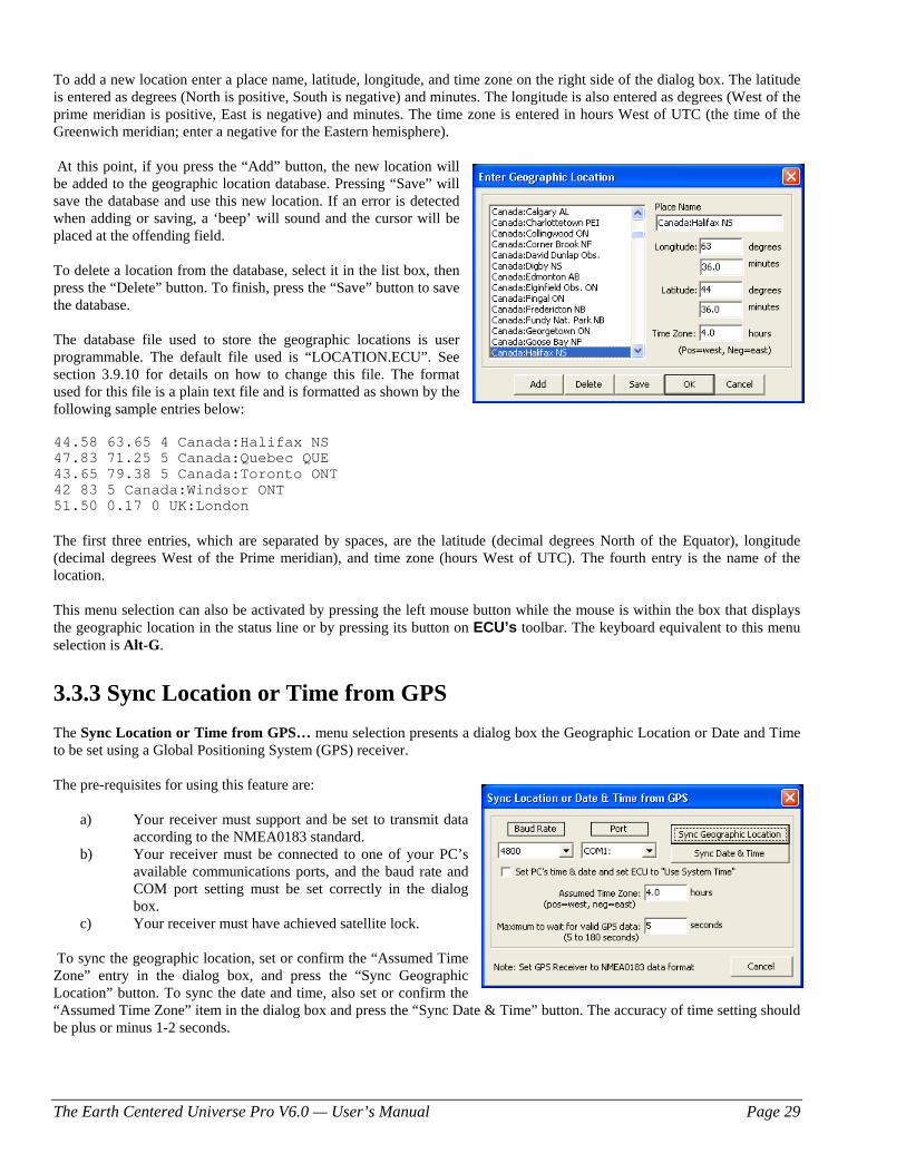
The Earth Centered Universe Pro V6.0 — User’s Manual Page 29
To add a new location enter a place name, latitude, longitude, and time zone on the right side of the dialog box. The latitude is entered as degrees (North is positive, South is negative) and minutes. The longitude is also entered as degrees (West of the prime meridian is positive, East is negative) and minutes. The time zone is entered in hours West of UTC (the time of the Greenwich meridian; enter a negative for the Eastern hemisphere). At this point, if you press the “Add” button, the new location will be added to the geographic location database. Pressing “Save” will save the database and use this new location. If an error is detected when adding or saving, a ‘beep’ will sound and the cursor will be placed at the offending field. To delete a location from the database, select it in the list box, then press the “Delete” button. To finish, press the “Save” button to save the database. The database file used to store the geographic locations is user programmable. The default file used is “LOCATION.ECU”. See section 3.9.10 for details on how to change this file. The format used for this file is a plain text file and is formatted as shown by the following sample entries below: 44.58 63.65 4 Canada:Halifax NS 47.83 71.25 5 Canada:Quebec QUE 43.65 79.38 5 Canada:Toronto ONT 42 83 5 Canada:Windsor ONT 51.50 0.17 0 UK:London The first three entries, which are separated by spaces, are the latitude (decimal degrees North of the Equator), longitude (decimal degrees West of the Prime meridian), and time zone (hours West of UTC). The fourth entry is the name of the location. This menu selection can also be activated by pressing the left mouse button while the mouse is within the box that displays the geographic location in the status line or by pressing its button on ECU’s toolbar. The keyboard equivalent to this menu selection is Alt-G.
3.3.3 Sync Location or Time from GPS The Sync Location or Time from GPS… menu selection presents a dialog box the Geographic Location or Date and Time to be set using a Global Positioning System (GPS) receiver. The pre-requisites for using this feature are:
a) Your receiver must support and be set to transmit data according to the NMEA0183 standard.
b) Your receiver must be connected to one of your PC’s available communications ports, and the baud rate and COM port setting must be set correctly in the dialog box.
c) Your receiver must have achieved satellite lock. To sync the geographic location, set or confirm the “Assumed Time Zone” entry in the dialog box, and press the “Sync Geographic Location” button. To sync the date and time, also set or confirm the “Assumed Time Zone” item in the dialog box and press the “Sync Date & Time” button. The accuracy of time setting should be plus or minus 1-2 seconds.
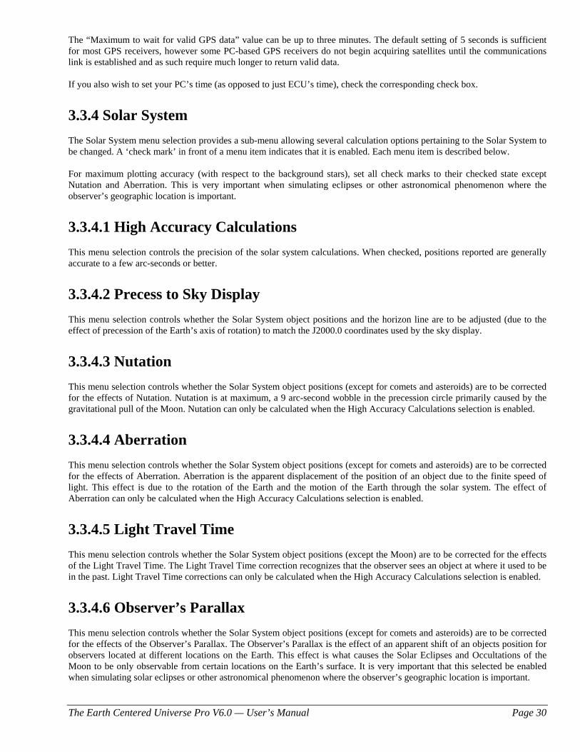
The Earth Centered Universe Pro V6.0 — User’s Manual Page 30
The “Maximum to wait for valid GPS data” value can be up to three minutes. The default setting of 5 seconds is sufficient for most GPS receivers, however some PC-based GPS receivers do not begin acquiring satellites until the communications link is established and as such require much longer to return valid data. If you also wish to set your PC’s time (as opposed to just ECU’s time), check the corresponding check box.
3.3.4 Solar System The Solar System menu selection provides a sub-menu allowing several calculation options pertaining to the Solar System to be changed. A ‘check mark’ in front of a menu item indicates that it is enabled. Each menu item is described below. For maximum plotting accuracy (with respect to the background stars), set all check marks to their checked state except Nutation and Aberration. This is very important when simulating eclipses or other astronomical phenomenon where the observer’s geographic location is important.
3.3.4.1 High Accuracy Calculations This menu selection controls the precision of the solar system calculations. When checked, positions reported are generally accurate to a few arc-seconds or better.
3.3.4.2 Precess to Sky Display This menu selection controls whether the Solar System object positions and the horizon line are to be adjusted (due to the effect of precession of the Earth’s axis of rotation) to match the J2000.0 coordinates used by the sky display.
3.3.4.3 Nutation This menu selection controls whether the Solar System object positions (except for comets and asteroids) are to be corrected for the effects of Nutation. Nutation is at maximum, a 9 arc-second wobble in the precession circle primarily caused by the gravitational pull of the Moon. Nutation can only be calculated when the High Accuracy Calculations selection is enabled.
3.3.4.4 Aberration This menu selection controls whether the Solar System object positions (except for comets and asteroids) are to be corrected for the effects of Aberration. Aberration is the apparent displacement of the position of an object due to the finite speed of light. This effect is due to the rotation of the Earth and the motion of the Earth through the solar system. The effect of Aberration can only be calculated when the High Accuracy Calculations selection is enabled.
3.3.4.5 Light Travel Time This menu selection controls whether the Solar System object positions (except the Moon) are to be corrected for the effects of the Light Travel Time. The Light Travel Time correction recognizes that the observer sees an object at where it used to be in the past. Light Travel Time corrections can only be calculated when the High Accuracy Calculations selection is enabled.
3.3.4.6 Observer’s Parallax This menu selection controls whether the Solar System object positions (except for comets and asteroids) are to be corrected for the effects of the Observer’s Parallax. The Observer’s Parallax is the effect of an apparent shift of an objects position for observers located at different locations on the Earth. This effect is what causes the Solar Eclipses and Occultations of the Moon to be only observable from certain locations on the Earth’s surface. It is very important that this selected be enabled when simulating solar eclipses or other astronomical phenomenon where the observer’s geographic location is important.
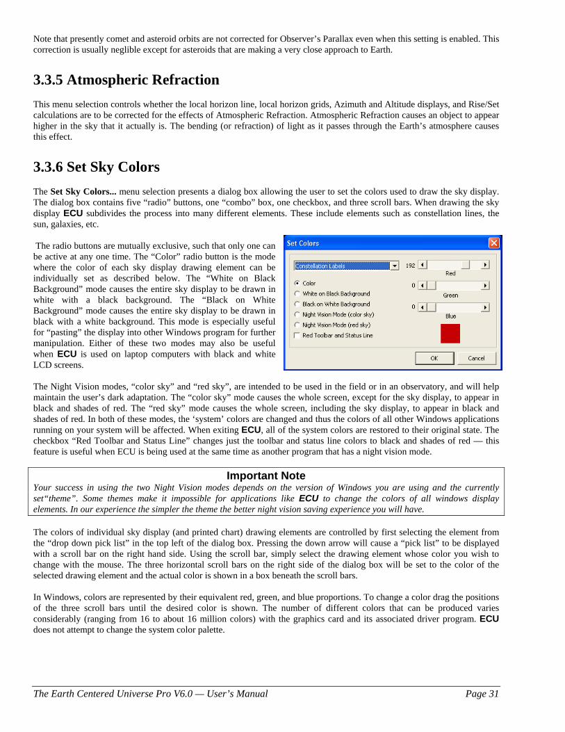
The Earth Centered Universe Pro V6.0 — User’s Manual Page 31
Note that presently comet and asteroid orbits are not corrected for Observer’s Parallax even when this setting is enabled. This correction is usually neglible except for asteroids that are making a very close approach to Earth.
3.3.5 Atmospheric Refraction This menu selection controls whether the local horizon line, local horizon grids, Azimuth and Altitude displays, and Rise/Set calculations are to be corrected for the effects of Atmospheric Refraction. Atmospheric Refraction causes an object to appear higher in the sky that it actually is. The bending (or refraction) of light as it passes through the Earth’s atmosphere causes this effect.
3.3.6 Set Sky Colors The Set Sky Colors... menu selection presents a dialog box allowing the user to set the colors used to draw the sky display. The dialog box contains five “radio” buttons, one “combo” box, one checkbox, and three scroll bars. When drawing the sky display ECU subdivides the process into many different elements. These include elements such as constellation lines, the sun, galaxies, etc. The radio buttons are mutually exclusive, such that only one can be active at any one time. The “Color” radio button is the mode where the color of each sky display drawing element can be individually set as described below. The “White on Black Background” mode causes the entire sky display to be drawn in white with a black background. The “Black on White Background” mode causes the entire sky display to be drawn in black with a white background. This mode is especially useful for “pasting” the display into other Windows program for further manipulation. Either of these two modes may also be useful when ECU is used on laptop computers with black and white LCD screens. The Night Vision modes, “color sky” and “red sky”, are intended to be used in the field or in an observatory, and will help maintain the user’s dark adaptation. The “color sky” mode causes the whole screen, except for the sky display, to appear in black and shades of red. The “red sky” mode causes the whole screen, including the sky display, to appear in black and shades of red. In both of these modes, the ‘system’ colors are changed and thus the colors of all other Windows applications running on your system will be affected. When exiting ECU, all of the system colors are restored to their original state. The checkbox “Red Toolbar and Status Line” changes just the toolbar and status line colors to black and shades of red — this feature is useful when ECU is being used at the same time as another program that has a night vision mode.
Important Note Your success in using the two Night Vision modes depends on the version of Windows you are using and the currently set“theme”. Some themes make it impossible for applications like ECU to change the colors of all windows display elements. In our experience the simpler the theme the better night vision saving experience you will have. The colors of individual sky display (and printed chart) drawing elements are controlled by first selecting the element from the “drop down pick list” in the top left of the dialog box. Pressing the down arrow will cause a “pick list” to be displayed with a scroll bar on the right hand side. Using the scroll bar, simply select the drawing element whose color you wish to change with the mouse. The three horizontal scroll bars on the right side of the dialog box will be set to the color of the selected drawing element and the actual color is shown in a box beneath the scroll bars. In Windows, colors are represented by their equivalent red, green, and blue proportions. To change a color drag the positions of the three scroll bars until the desired color is shown. The number of different colors that can be produced varies considerably (ranging from 16 to about 16 million colors) with the graphics card and its associated driver program. ECU does not attempt to change the system color palette.
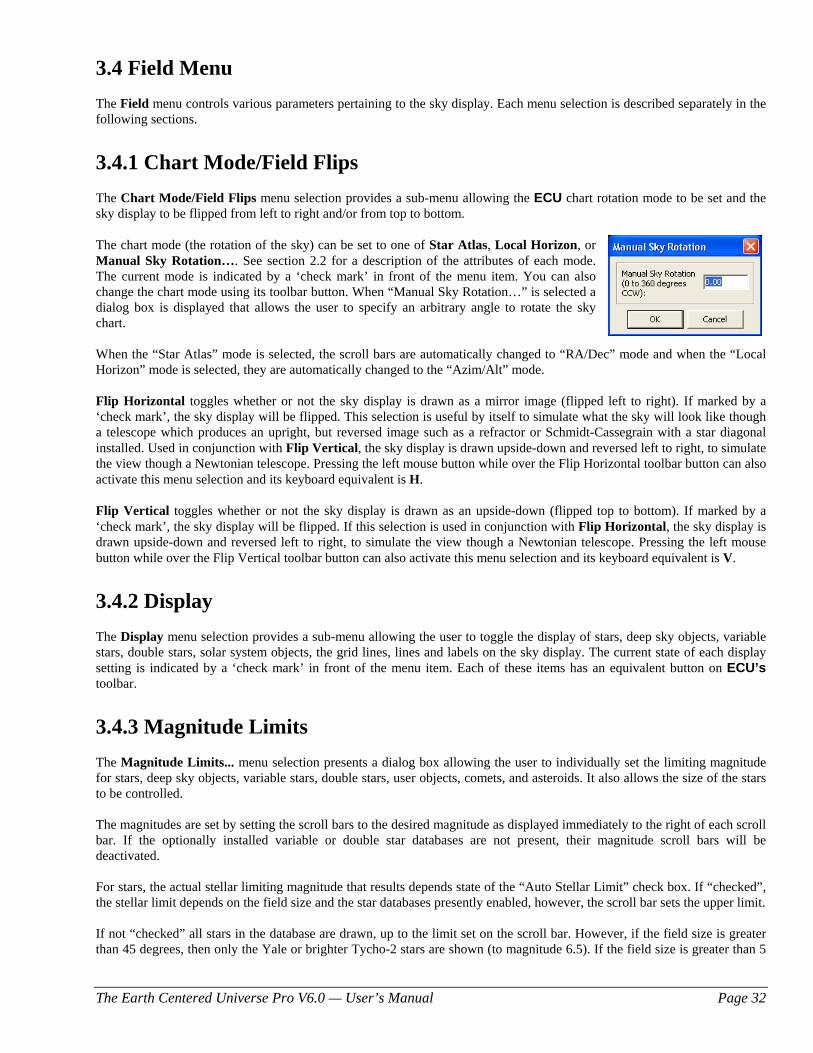
The Earth Centered Universe Pro V6.0 — User’s Manual Page 32
3.4 Field Menu The Field menu controls various parameters pertaining to the sky display. Each menu selection is described separately in the following sections.
3.4.1 Chart Mode/Field Flips The Chart Mode/Field Flips menu selection provides a sub-menu allowing the ECU chart rotation mode to be set and the sky display to be flipped from left to right and/or from top to bottom. The chart mode (the rotation of the sky) can be set to one of Star Atlas, Local Horizon, or Manual Sky Rotation…. See section 2.2 for a description of the attributes of each mode. The current mode is indicated by a ‘check mark’ in front of the menu item. You can also change the chart mode using its toolbar button. When “Manual Sky Rotation…” is selected a dialog box is displayed that allows the user to specify an arbitrary angle to rotate the sky chart. When the “Star Atlas” mode is selected, the scroll bars are automatically changed to “RA/Dec” mode and when the “Local Horizon” mode is selected, they are automatically changed to the “Azim/Alt” mode. Flip Horizontal toggles whether or not the sky display is drawn as a mirror image (flipped left to right). If marked by a ‘check mark’, the sky display will be flipped. This selection is useful by itself to simulate what the sky will look like though a telescope which produces an upright, but reversed image such as a refractor or Schmidt-Cassegrain with a star diagonal installed. Used in conjunction with Flip Vertical, the sky display is drawn upside-down and reversed left to right, to simulate the view though a Newtonian telescope. Pressing the left mouse button while over the Flip Horizontal toolbar button can also activate this menu selection and its keyboard equivalent is H. Flip Vertical toggles whether or not the sky display is drawn as an upside-down (flipped top to bottom). If marked by a ‘check mark’, the sky display will be flipped. If this selection is used in conjunction with Flip Horizontal, the sky display is drawn upside-down and reversed left to right, to simulate the view though a Newtonian telescope. Pressing the left mouse button while over the Flip Vertical toolbar button can also activate this menu selection and its keyboard equivalent is V.
3.4.2 Display The Display menu selection provides a sub-menu allowing the user to toggle the display of stars, deep sky objects, variable stars, double stars, solar system objects, the grid lines, lines and labels on the sky display. The current state of each display setting is indicated by a ‘check mark’ in front of the menu item. Each of these items has an equivalent button on ECU’s toolbar.
3.4.3 Magnitude Limits The Magnitude Limits... menu selection presents a dialog box allowing the user to individually set the limiting magnitude for stars, deep sky objects, variable stars, double stars, user objects, comets, and asteroids. It also allows the size of the stars to be controlled. The magnitudes are set by setting the scroll bars to the desired magnitude as displayed immediately to the right of each scroll bar. If the optionally installed variable or double star databases are not present, their magnitude scroll bars will be deactivated.
For stars, the actual stellar limiting magnitude that results depends state of the “Auto Stellar Limit” check box. If “checked”, the stellar limit depends on the field size and the star databases presently enabled, however, the scroll bar sets the upper limit. If not “checked” all stars in the database are drawn, up to the limit set on the scroll bar. However, if the field size is greater than 45 degrees, then only the Yale or brighter Tycho-2 stars are shown (to magnitude 6.5). If the field size is greater than 5
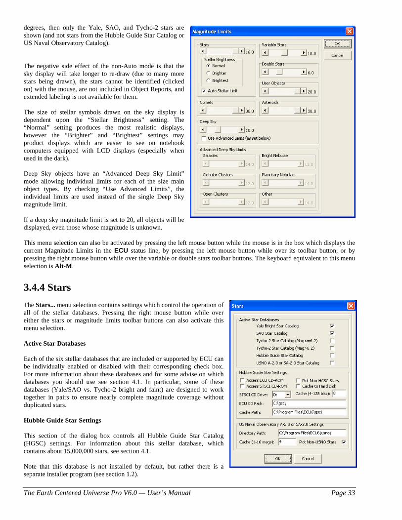
The Earth Centered Universe Pro V6.0 — User’s Manual Page 33
degrees, then only the Yale, SAO, and Tycho-2 stars are shown (and not stars from the Hubble Guide Star Catalog or US Naval Observatory Catalog). The negative side effect of the non-Auto mode is that the sky display will take longer to re-draw (due to many more stars being drawn), the stars cannot be identified (clicked on) with the mouse, are not included in Object Reports, and extended labeling is not available for them. The size of stellar symbols drawn on the sky display is dependent upon the “Stellar Brightness” setting. The “Normal” setting produces the most realistic displays, however the “Brighter” and “Brightest” settings may product displays which are easier to see on notebook computers equipped with LCD displays (especially when used in the dark). Deep Sky objects have an “Advanced Deep Sky Limit” mode allowing individual limits for each of the size main object types. By checking “Use Advanced Limits”, the individual limits are used instead of the single Deep Sky magnitude limit. If a deep sky magnitude limit is set to 20, all objects will be displayed, even those whose magnitude is unknown. This menu selection can also be activated by pressing the left mouse button while the mouse is in the box which displays the current Magnitude Limits in the ECU status line, by pressing the left mouse button while over its toolbar button, or by pressing the right mouse button while over the variable or double stars toolbar buttons. The keyboard equivalent to this menu selection is Alt-M.
3.4.4 Stars The Stars... menu selection contains settings which control the operation of all of the stellar databases. Pressing the right mouse button while over either the stars or magnitude limits toolbar buttons can also activate this menu selection. Active Star Databases Each of the six stellar databases that are included or supported by ECU can be individually enabled or disabled with their corresponding check box. For more information about these databases and for some advise on which databases you should use see section 4.1. In particular, some of these databases (Yale/SAO vs. Tycho-2 bright and faint) are designed to work together in pairs to ensure nearly complete magnitude coverage without duplicated stars. Hubble Guide Star Settings This section of the dialog box controls all Hubble Guide Star Catalog (HGSC) settings. For information about this stellar database, which contains about 15,000,000 stars, see section 4.1. Note that this database is not installed by default, but rather there is a separate installer program (see section 1.2).
The Earth Centered Universe Pro V6.0 — User’s Manual Page 34
After configured, and enabled (see Active Star Databases above), the HGSC stars are drawn whenever the field size is smaller than 5 degrees in vertical height. This limit allows for a fast re-draw time and a density of stars that is not overwhelming. The following items relating to the HGSC can be configured, however V6.0 users should not have to change any of these settings. Most of these relate to earlier verions of ECU which contained the HGSC on a CD-ROM – they are left available so that users with an ECU or STSCI CD-ROM can still use it.
a) Access ECU CD-ROM — if checked, the ECU CD-ROM is accessed. If it is not checked, then only the data stored on your hard disk is used. If you have copied regions of the sky on to your hard disk (as described in sections 3.8.6), you should disable this check box to prevent further CD-ROM accesses.
b) Access STSCI CD-ROM — if checked, the STSCI CD-ROM is accessed. If it is not checked, then only the data stored on your hard disk is used. If you have copied regions of the sky on to your hard disk (as described in sections 3.8.6), you should disable this check box to prevent further CD-ROM accesses. Each STSCI CD covers about one hemisphere of sky, so you will have to insert the CD-ROM in the drive that covers the area of sky you are interested in.
c) Plot Non-HGSC Stars — if checked, the non-HGSC stars (Yale, SAO, and Tycho-2) are plotted in addition to the HGSC stars. The feature is provided because V1.0 of the HGSC CD-ROMs published by The Space Telescope Science Institute (STSCI) did not include stars brighter than magnitude 7. If you have the ECU CD-ROM or V1.1 of the STSCI CD-ROMs, this item should not be checked.
d) Cache to Hard Disk — if checked, data read from the CD-ROM is copied (cached) to your hard disk for faster future access.
e) STSCI CD Drive — set this item to the drive letter of your CD-ROM drive where you will insert the STSCI CD-ROM — usually “D” or “E”.
f) Cache — The HGSC is divided into over 9000 regions of the sky. This entry determines how many of these regions will be “cached” in memory. Values from 4 to 128 regions can be entered. If you have a lot of memory in your system, it is recommended that higher numbers be used.
g) ECU CD Path — set this item location of the HGSC files on your ECU CD-ROM. This setting will normally be set correctly during installation of ECU.
h) Cache Path — set this item location where HGSC cache files are to be stored (see d) above and section 3.8.6). This setting will normally be set correctly during installation of ECU however you may wish to change it to a hard disk with more space available, other than where ECU is installed.
US Naval Observatory Settings This section of the dialog box controls all settings used to access the US Naval Observatory’s (USNO) A-2.0 and SA-2.0 star catalogs. Note that these databases are not included with ECU due to licensing issues. They can, however, be downloaded from the Internet by individual users. For information about these stellar databases, which contain up to ~500,000,000 stars, see section 4.1.5. After configured, and enabled (see Active Star Databases above), the USNO stars are drawn whenever the field size is smaller than 5 degrees in vertical height. This limit allows for a fast re-draw time and a density of stars that is not overwhelming. The following items can be configured.
a) Directory — set this item to the location of the USNO files. This may be a location on your hard disk or perhaps on a DVD or CD-ROM. If changing CDs or DVDs, note that ECU only looks for new USNO files when the U button is pressed or when this dialog box exited with the “OK” button.
b) Cache — The USNO databases are divided into many regions of the sky. This entry determines how much memory is allocated in order to “cache” USNO stars in memory. Values from 1 to 16 megabytes can be entered.
c) Plot Non-USNO Stars — if checked, the non-USNO stars (Yale, SAO, and Tycho-2) are plotted in addition to the USNO stars. This feature is provided because the USNO database is missing many bright stars and therefore is best used in conjunction with either the Tycho-2 or Yale/SAO databases.
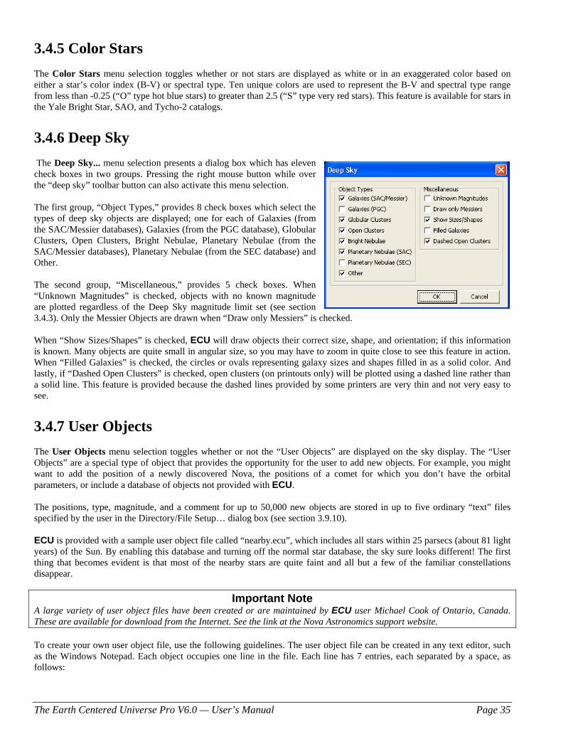
The Earth Centered Universe Pro V6.0 — User’s Manual Page 35
3.4.5 Color Stars The Color Stars menu selection toggles whether or not stars are displayed as white or in an exaggerated color based on either a star’s color index (B-V) or spectral type. Ten unique colors are used to represent the B-V and spectral type range from less than -0.25 (“O” type hot blue stars) to greater than 2.5 (“S” type very red stars). This feature is available for stars in the Yale Bright Star, SAO, and Tycho-2 catalogs.
3.4.6 Deep Sky The Deep Sky... menu selection presents a dialog box which has eleven check boxes in two groups. Pressing the right mouse button while over the “deep sky” toolbar button can also activate this menu selection. The first group, “Object Types,” provides 8 check boxes which select the types of deep sky objects are displayed; one for each of Galaxies (from the SAC/Messier databases), Galaxies (from the PGC database), Globular Clusters, Open Clusters, Bright Nebulae, Planetary Nebulae (from the SAC/Messier databases), Planetary Nebulae (from the SEC database) and Other. The second group, “Miscellaneous,” provides 5 check boxes. When “Unknown Magnitudes” is checked, objects with no known magnitude are plotted regardless of the Deep Sky magnitude limit set (see section 3.4.3). Only the Messier Objects are drawn when “Draw only Messiers” is checked. When “Show Sizes/Shapes” is checked, ECU will draw objects their correct size, shape, and orientation; if this information is known. Many objects are quite small in angular size, so you may have to zoom in quite close to see this feature in action. When “Filled Galaxies” is checked, the circles or ovals representing galaxy sizes and shapes filled in as a solid color. And lastly, if “Dashed Open Clusters” is checked, open clusters (on printouts only) will be plotted using a dashed line rather than a solid line. This feature is provided because the dashed lines provided by some printers are very thin and not very easy to see.
3.4.7 User Objects The User Objects menu selection toggles whether or not the “User Objects” are displayed on the sky display. The “User Objects” are a special type of object that provides the opportunity for the user to add new objects. For example, you might want to add the position of a newly discovered Nova, the positions of a comet for which you don’t have the orbital parameters, or include a database of objects not provided with ECU. The positions, type, magnitude, and a comment for up to 50,000 new objects are stored in up to five ordinary “text” files specified by the user in the Directory/File Setup… dialog box (see section 3.9.10). ECU is provided with a sample user object file called “nearby.ecu”, which includes all stars within 25 parsecs (about 81 light years) of the Sun. By enabling this database and turning off the normal star database, the sky sure looks different! The first thing that becomes evident is that most of the nearby stars are quite faint and all but a few of the familiar constellations disappear.
Important Note A large variety of user object files have been created or are maintained by ECU user Michael Cook of Ontario, Canada. These are available for download from the Internet. See the link at the Nova Astronomics support website. To create your own user object file, use the following guidelines. The user object file can be created in any text editor, such as the Windows Notepad. Each object occupies one line in the file. Each line has 7 entries, each separated by a space, as follows:
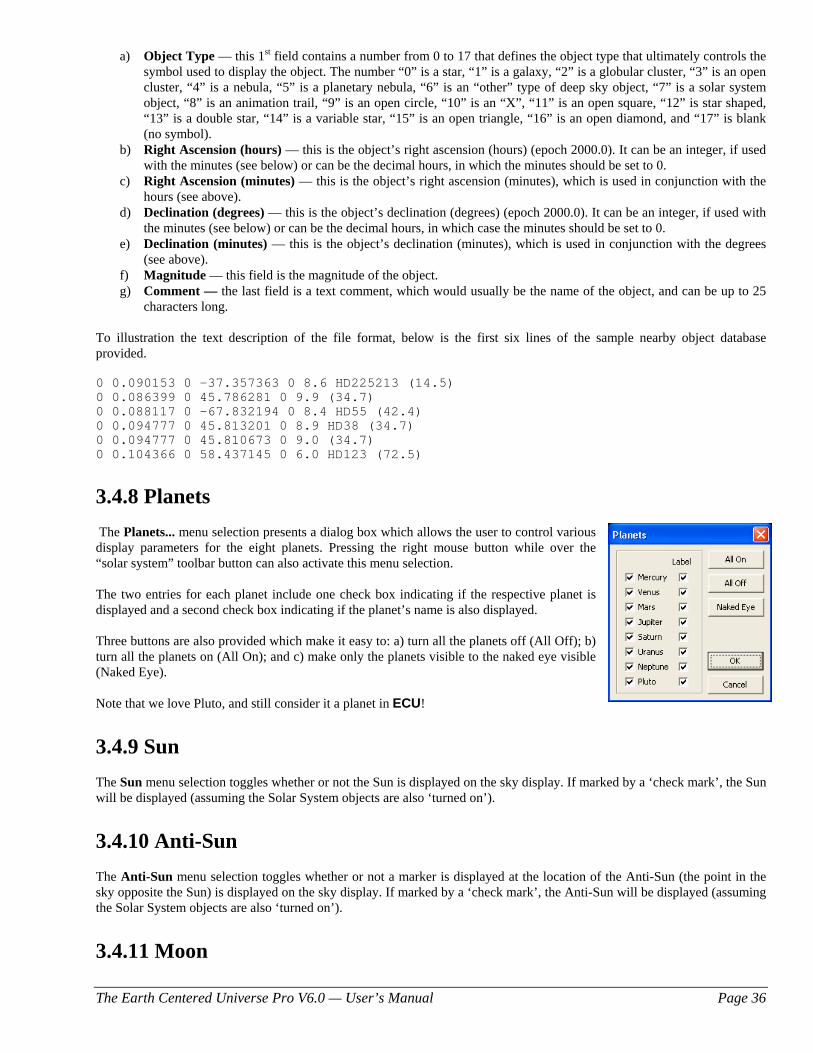
The Earth Centered Universe Pro V6.0 — User’s Manual Page 36
a) Object Type — this 1st field contains a number from 0 to 17 that defines the object type that ultimately controls the symbol used to display the object. The number “0” is a star, “1” is a galaxy, “2” is a globular cluster, “3” is an open cluster, “4” is a nebula, “5” is a planetary nebula, “6” is an “other” type of deep sky object, “7” is a solar system object, “8” is an animation trail, “9” is an open circle, “10” is an “X”, “11” is an open square, “12” is star shaped, “13” is a double star, “14” is a variable star, “15” is an open triangle, “16” is an open diamond, and “17” is blank (no symbol).
b) Right Ascension (hours) — this is the object’s right ascension (hours) (epoch 2000.0). It can be an integer, if used with the minutes (see below) or can be the decimal hours, in which the minutes should be set to 0.
c) Right Ascension (minutes) — this is the object’s right ascension (minutes), which is used in conjunction with the hours (see above).
d) Declination (degrees) — this is the object’s declination (degrees) (epoch 2000.0). It can be an integer, if used with the minutes (see below) or can be the decimal hours, in which case the minutes should be set to 0.
e) Declination (minutes) — this is the object’s declination (minutes), which is used in conjunction with the degrees (see above).
f) Magnitude — this field is the magnitude of the object. g) Comment — the last field is a text comment, which would usually be the name of the object, and can be up to 25
characters long. To illustration the text description of the file format, below is the first six lines of the sample nearby object database provided. 0 0.090153 0 -37.357363 0 8.6 HD225213 (14.5) 0 0.086399 0 45.786281 0 9.9 (34.7) 0 0.088117 0 -67.832194 0 8.4 HD55 (42.4) 0 0.094777 0 45.813201 0 8.9 HD38 (34.7) 0 0.094777 0 45.810673 0 9.0 (34.7) 0 0.104366 0 58.437145 0 6.0 HD123 (72.5)
3.4.8 Planets The Planets... menu selection presents a dialog box which allows the user to control various display parameters for the eight planets. Pressing the right mouse button while over the “solar system” toolbar button can also activate this menu selection. The two entries for each planet include one check box indicating if the respective planet is displayed and a second check box indicating if the planet’s name is also displayed.
Three buttons are also provided which make it easy to: a) turn all the planets off (All Off); b) turn all the planets on (All On); and c) make only the planets visible to the naked eye visible (Naked Eye). Note that we love Pluto, and still consider it a planet in ECU!
3.4.9 Sun The Sun menu selection toggles whether or not the Sun is displayed on the sky display. If marked by a ‘check mark’, the Sun will be displayed (assuming the Solar System objects are also ‘turned on’).
3.4.10 Anti-Sun The Anti-Sun menu selection toggles whether or not a marker is displayed at the location of the Anti-Sun (the point in the sky opposite the Sun) is displayed on the sky display. If marked by a ‘check mark’, the Anti-Sun will be displayed (assuming the Solar System objects are also ‘turned on’).
3.4.11 Moon
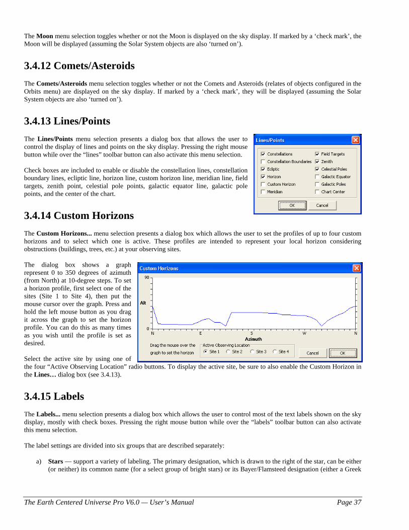
The Earth Centered Universe Pro V6.0 — User’s Manual Page 37
The Moon menu selection toggles whether or not the Moon is displayed on the sky display. If marked by a ‘check mark’, the Moon will be displayed (assuming the Solar System objects are also ‘turned on’).
3.4.12 Comets/Asteroids The Comets/Asteroids menu selection toggles whether or not the Comets and Asteroids (relates of objects configured in the Orbits menu) are displayed on the sky display. If marked by a ‘check mark’, they will be displayed (assuming the Solar System objects are also ‘turned on’).
3.4.13 Lines/Points The Lines/Points menu selection presents a dialog box that allows the user to control the display of lines and points on the sky display. Pressing the right mouse button while over the “lines” toolbar button can also activate this menu selection.
Check boxes are included to enable or disable the constellation lines, constellation boundary lines, ecliptic line, horizon line, custom horizon line, meridian line, field targets, zenith point, celestial pole points, galactic equator line, galactic pole points, and the center of the chart.
3.4.14 Custom Horizons The Custom Horizons... menu selection presents a dialog box which allows the user to set the profiles of up to four custom horizons and to select which one is active. These profiles are intended to represent your local horizon considering obstructions (buildings, trees, etc.) at your observing sites. The dialog box shows a graph represent 0 to 350 degrees of azimuth (from North) at 10-degree steps. To set a horizon profile, first select one of the sites (Site 1 to Site 4), then put the mouse cursor over the graph. Press and hold the left mouse button as you drag it across the graph to set the horizon profile. You can do this as many times as you wish until the profile is set as desired. Select the active site by using one of the four “Active Observing Location” radio buttons. To display the active site, be sure to also enable the Custom Horizon in the Lines… dialog box (see 3.4.13).
3.4.15 Labels The Labels... menu selection presents a dialog box which allows the user to control most of the text labels shown on the sky display, mostly with check boxes. Pressing the right mouse button while over the “labels” toolbar button can also activate this menu selection. The label settings are divided into six groups that are described separately:
a) Stars — support a variety of labeling. The primary designation, which is drawn to the right of the star, can be either (or neither) its common name (for a select group of bright stars) or its Bayer/Flamsteed designation (either a Greek
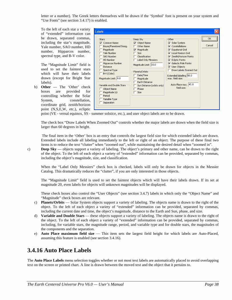
The Earth Centered Universe Pro V6.0 — User’s Manual Page 38
letter or a number). The Greek letters themselves will be drawn if the ‘Symbol’ font is present on your system and “Use Fonts” (see section 3.4.17) is enabled.
To the left of each star a variety
of “extended” information can be drawn, separated commas, including the star’s magnitude, Yale number, SAO number, HD number, Hipparcos number, spectral type, and B-V color.
The “Magnitude Limit” field is
used to set the faintest stars which will have their labels drawn (except for Bright Star labels).
b) Other — The ‘Other’ check boxes are provided for controlling whether the Solar System, constellation, coordinate grid, zenith/horizon point (N,S,E,W, etc.), ecliptic point (VE - vernal equinox, SS - summer solstice, etc.), and user object labels are to be drawn.
The check box “Draw Labels When Zoomed Out” controls whether the major labels are drawn when the field size is larger than 60 degrees in height.
The final item in the ‘Other’ box is an entry that controls the largest field size for which extended labels are drawn. Extended labels include all labeling immediately to the left or right of an object. The purpose of these final two items is to reduce the text “clutter” when “zoomed out”, while maintaining the desired detail when “zoomed in”.
c) Deep Sky — objects support a variety of labeling. The object’s primary and other name, can be drawn to the right of the object. To the left of each object a variety of “extended” information can be provided, separated by commas, including the object’s magnitude, size, and classification.
When the “Label Only Messiers” check box is checked, labels will only be drawn for objects in the Messier
Catalog. This dramatically reduces the “clutter”, if you are only interested in those objects. The “Magnitude Limit” field is used to set the faintest objects which will have their labels drawn. If its set at
magnitude 20, even labels for objects will unknown magnitudes will be displayed.
These check boxes also control the “User Objects” (see section 3.4.7) labels in which only the “Object Name” and “Magnitude” check boxes are relevant.
c) Planets/Orbits — Solar System objects support a variety of labeling. The objects name is drawn to the right of the object. To the left of each object a variety of “extended” information can be provided, separated by commas, including the current date and time, the object’s magnitude, distance to the Earth and Sun, phase, and size.
d) Variable and Double Stars — these objects support a variety of labeling. The objects name is drawn to the right of the object. To the left of each object a variety of “extended” information can be provided, separated by commas, including, for variable stars, the magnitude range, period, and variable type and for double stars, the magnitudes of the components and the separation.
e) Auto Place maximum field size — This item sets the largest field height for which labels are Auto-Placed, assuming this feature is enabled (see section 3.4.16).
3.4.16 Auto Place Labels The Auto Place Labels menu selection toggles whether or not most text labels are automatically placed to avoid overlapping text on the screen or printed chart. A line is drawn between the moved text and the object that it pertains to.
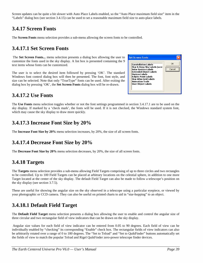
The Earth Centered Universe Pro V6.0 — User’s Manual Page 39
Screen updates can be quite a bit slower with Auto Place Labels enabled, so the “Auto Place maximum field size” item in the “Labels” dialog box (see section 3.4.15) can be used to set a reasonable maximum field size to auto-place labels.
3.4.17 Screen Fonts The Screen Fonts menu selection provides a sub-menu allowing the screen fonts to be controlled.
3.4.17.1 Set Screen Fonts The Set Screen Fonts... menu selection presents a dialog box allowing the user to customize the fonts used in the sky display. A list box is presented containing the 9 text items whose fonts can be customized.
The user is to select the desired item followed by pressing ‘OK’. The standard Windows font control dialog box will then be presented. The font, font style, and size can be selected. Note that only “TrueType” fonts can be used. After exiting the dialog box by pressing ‘OK’, the Set Screen Fonts dialog box will be re-drawn.
3.4.17.2 Use Fonts The Use Fonts menu selection toggles whether or not the font settings programmed in section 3.4.17.1 are to be used on the sky display. If marked by a ‘check mark’, the fonts will be used. If it is not checked, the Windows standard system font, which may cause the sky display to draw more quickly.
3.4.17.3 Increase Font Size by 20% The Increase Font Size by 20% menu selection increases, by 20%, the size of all screen fonts.
3.4.17.4 Decrease Font Size by 20% The Decrease Font Size by 20% menu selection decreases, by 20%, the size of all screen fonts.
3.4.18 Targets The Targets menu selection provides a sub-menu allowing Field Targets comprising of up to three circles and two rectangles to be controlled. Up to 100 Field Targets can be placed at arbitrary locations on the celestial sphere, in addition to one more Target located at the center of the sky display. The default Field Target can also be made to follow a telescope’s position on the sky display (see section 3.7.5). These are useful for showing the angular size on the sky observed in a telescope using a particular eyepiece, or viewed by your photographic or CCD camera. They can also be useful on printed charts to aid in “star-hopping” to an object.
3.4.18.1 Default Field Target The Default Field Target menu selection presents a dialog box allowing the user to enable and control the angular size of three circular and two rectangular field of view indicators that can be drawn on the sky display. Angular size values for each field of view indicator can be entered from 0.05 to 90 degrees. Each field of view can be individually enabled by “checking” its corresponding “Enable” check box. The rectangular fields of view indicators can also be arbitrarily rotated over a range of 0 to 180 degrees. The “Set to Telrad” and “Set to QuikFinder” buttons automatically set the fields of view to match the popular Telrad and Rigel QuikFinder zero-power telescope finder devices.
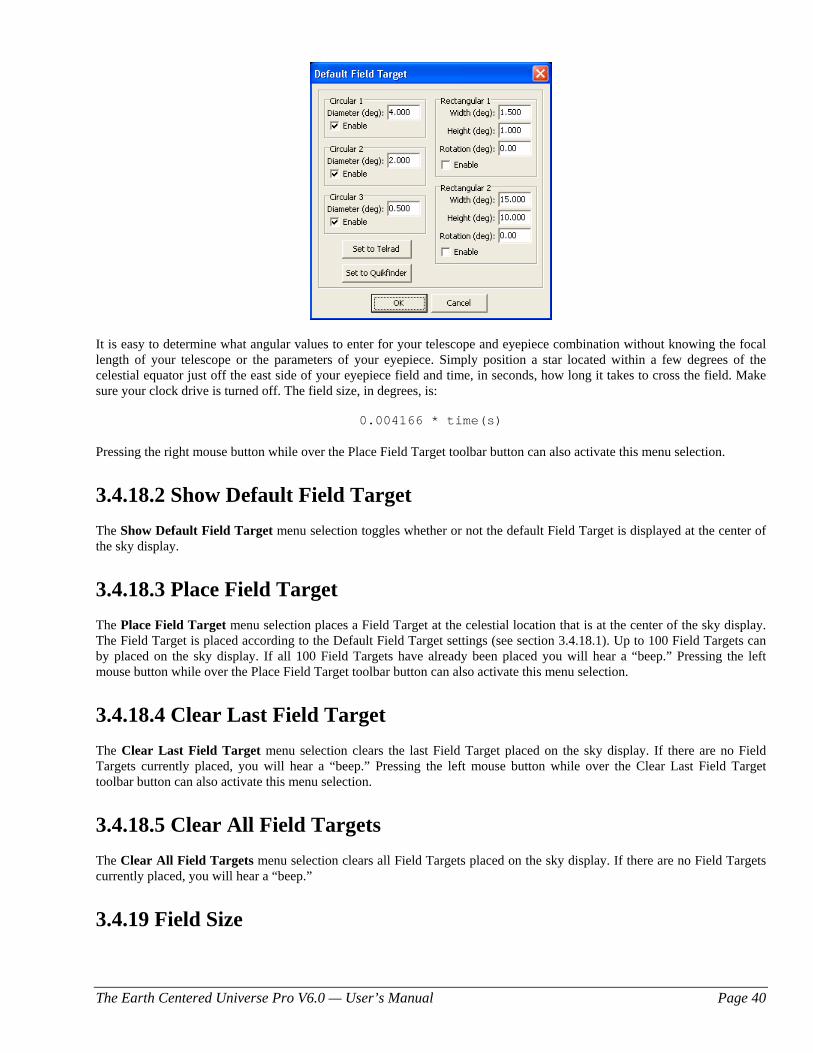
The Earth Centered Universe Pro V6.0 — User’s Manual Page 40
It is easy to determine what angular values to enter for your telescope and eyepiece combination without knowing the focal length of your telescope or the parameters of your eyepiece. Simply position a star located within a few degrees of the celestial equator just off the east side of your eyepiece field and time, in seconds, how long it takes to cross the field. Make sure your clock drive is turned off. The field size, in degrees, is:
0.004166 * time(s)
Pressing the right mouse button while over the Place Field Target toolbar button can also activate this menu selection.
3.4.18.2 Show Default Field Target The Show Default Field Target menu selection toggles whether or not the default Field Target is displayed at the center of the sky display.
3.4.18.3 Place Field Target The Place Field Target menu selection places a Field Target at the celestial location that is at the center of the sky display. The Field Target is placed according to the Default Field Target settings (see section 3.4.18.1). Up to 100 Field Targets can by placed on the sky display. If all 100 Field Targets have already been placed you will hear a “beep.” Pressing the left mouse button while over the Place Field Target toolbar button can also activate this menu selection.
3.4.18.4 Clear Last Field Target The Clear Last Field Target menu selection clears the last Field Target placed on the sky display. If there are no Field Targets currently placed, you will hear a “beep.” Pressing the left mouse button while over the Clear Last Field Target toolbar button can also activate this menu selection.
3.4.18.5 Clear All Field Targets The Clear All Field Targets menu selection clears all Field Targets placed on the sky display. If there are no Field Targets currently placed, you will hear a “beep.”
3.4.19 Field Size
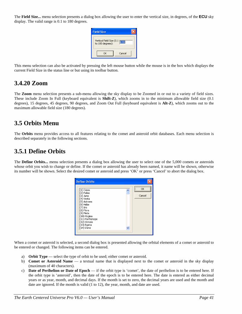
The Earth Centered Universe Pro V6.0 — User’s Manual Page 41
The Field Size... menu selection presents a dialog box allowing the user to enter the vertical size, in degrees, of the ECU sky display. The valid range is 0.1 to 180 degrees.
This menu selection can also be activated by pressing the left mouse button while the mouse is in the box which displays the current Field Size in the status line or but using its toolbar button.
3.4.20 Zoom The Zoom menu selection presents a sub-menu allowing the sky display to be Zoomed in or out to a variety of field sizes. These include Zoom In Full (keyboard equivalent is Shift-Z), which zooms in to the minimum allowable field size (0.1 degrees), 15 degrees, 45 degrees, 90 degrees, and Zoom Out Full (keyboard equivalent is Alt-Z), which zooms out to the maximum allowable field size (180 degrees).
3.5 Orbits Menu The Orbits menu provides access to all features relating to the comet and asteroid orbit databases. Each menu selection is described separately in the following sections.
3.5.1 Define Orbits The Define Orbits... menu selection presents a dialog box allowing the user to select one of the 5,000 comets or asteroids whose orbit you wish to change or define. If the comet or asteroid has already been named, it name will be shown, otherwise its number will be shown. Select the desired comet or asteroid and press ‘OK’ or press ‘Cancel’ to abort the dialog box.
When a comet or asteroid is selected, a second dialog box is presented allowing the orbital elements of a comet or asteroid to be entered or changed. The following items can be entered.
a) Orbit Type — select the type of orbit to be used; either comet or asteroid. b) Comet or Asteroid Name — a textual name that is displayed next to the comet or asteroid in the sky display
(maximum of 40 characters). c) Date of Perihelion or Date of Epoch — if the orbit type is ‘comet’, the date of perihelion is to be entered here. If
the orbit type is ‘asteroid’, then the date of the epoch is to be entered here. The date is entered as either decimal years or as year, month, and decimal days. If the month is set to zero, the decimal years are used and the month and date are ignored. If the month is valid (1 to 12), the year, month, and date are used.
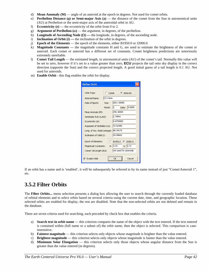
The Earth Centered Universe Pro V6.0 — User’s Manual Page 42
d) Mean Anomaly (M) — angle of an asteroid at the epoch in degrees. Not used for comet orbits. e) Perihelion Distance (q) or Semi-major Axis (a) — the distance of the comet from the Sun in astronomical units
(AU) at Perihelion or the semi-major axis of the asteroidal orbit in AU. f) Eccentricity (e) — the eccentricity of the orbit from 0 to 2. g) Argument of Perihelion (ω) — the argument, in degrees, of the perihelion. h) Longitude of Ascending Node (Ω) — the longitude, in degrees, of the ascending node. i) Inclination of Orbit (i) — the inclination of the orbit in degrees. j) Epoch of the Elements — the epoch of the elements, either B1950.0 or J2000.0. k) Magnitude Constants — the magnitude constants H and G, are used to estimate the brightness of the comet or
asteroid. Each comet or asteroid has a different set of constants. Comet brightness predictions are notoriously extremely unreliable.
l) Comet Tail Length — the estimated length, in astronomical units (AU) of the comet’s tail. Normally this value will be set to zero, however if it’s set to a value greater than zero, ECU projects the tail onto sky display in the correct direction (opposite the Sun) and the correct projected length. A good initial guess of a tail length is 0.1 AU. Not used for asteroids.
m) Enable Orbit - this flag enables the orbit for display.
If an orbit has a name and is ‘enabled’, it will be subsequently be referred to by its name instead of just “Comet/Asteroid 1”, etc.
3.5.2 Filter Orbits The Filter Orbits... menu selection presents a dialog box allowing the user to search through the currently loaded database of orbital elements and to select orbits based on several criteria using the current date, time, and geographic location. These selected orbits are enabled for display, the rest are disabled. Note that the non-selected orbits are not deleted and remain in the database.
There are seven criteria used for searching, each preceded by check box that enables the criteria.
a) Search text in orbit name — this criterion compares the name of the object with the text entered. If the text entered is contained within (full name or a subset of) the orbit name, then the object is selected. This comparison is case-insensitive.
b) Faintest magnitude — this criterion selects only objects whose magnitude is brighter than the value entered. c) Brightest magnitude — this criterion selects only objects whose magnitude is fainter than the value entered. d) Minimum Solar Elongation — this criterion selects only those objects whose angular distance from the Sun is
greater than the value entered (in degrees).
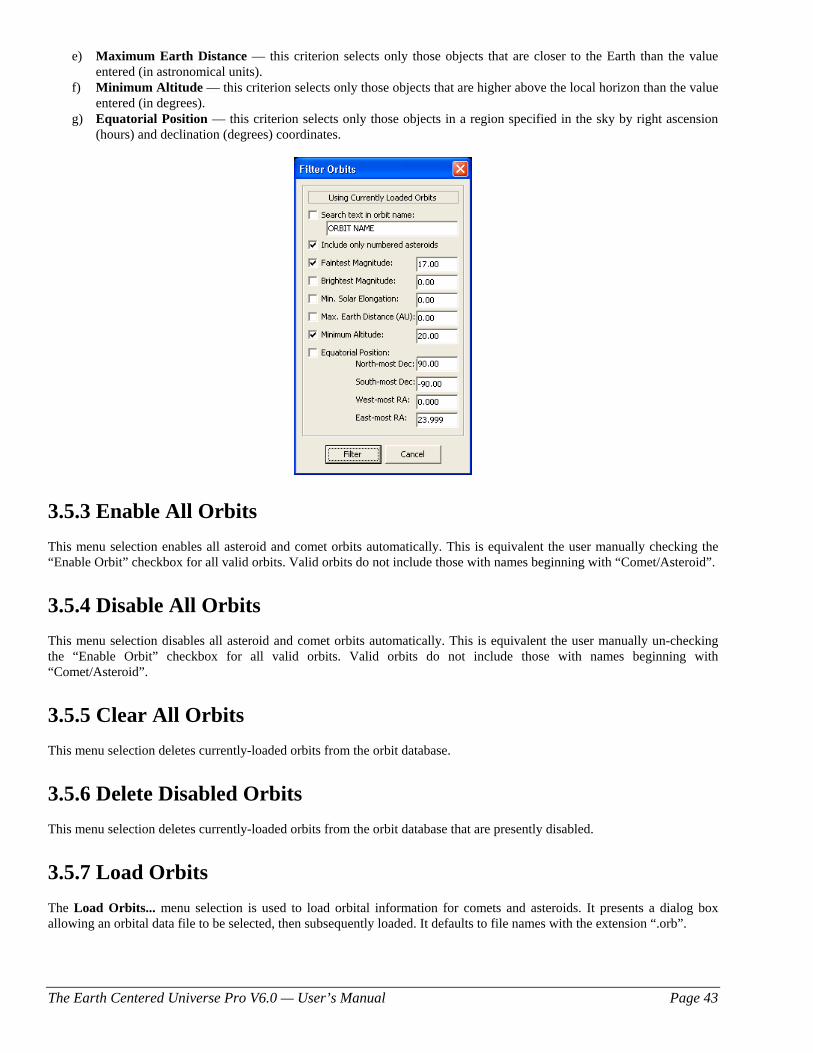
The Earth Centered Universe Pro V6.0 — User’s Manual Page 43
e) Maximum Earth Distance — this criterion selects only those objects that are closer to the Earth than the value entered (in astronomical units).
f) Minimum Altitude — this criterion selects only those objects that are higher above the local horizon than the value entered (in degrees).
g) Equatorial Position — this criterion selects only those objects in a region specified in the sky by right ascension (hours) and declination (degrees) coordinates.
3.5.3 Enable All Orbits This menu selection enables all asteroid and comet orbits automatically. This is equivalent the user manually checking the “Enable Orbit” checkbox for all valid orbits. Valid orbits do not include those with names beginning with “Comet/Asteroid”.
3.5.4 Disable All Orbits This menu selection disables all asteroid and comet orbits automatically. This is equivalent the user manually un-checking the “Enable Orbit” checkbox for all valid orbits. Valid orbits do not include those with names beginning with “Comet/Asteroid”.
3.5.5 Clear All Orbits This menu selection deletes currently-loaded orbits from the orbit database.
3.5.6 Delete Disabled Orbits This menu selection deletes currently-loaded orbits from the orbit database that are presently disabled.
3.5.7 Load Orbits The Load Orbits... menu selection is used to load orbital information for comets and asteroids. It presents a dialog box allowing an orbital data file to be selected, then subsequently loaded. It defaults to file names with the extension “.orb”.
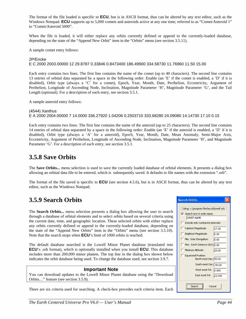
The Earth Centered Universe Pro V6.0 — User’s Manual Page 44
The format of the file loaded is specific to ECU, but is in ASCII format, thus can be altered by any text editor, such as the Windows Notepad. ECU supports up to 5,000 comets and asteroids active at any one time; referred to as “Comet/Asteroid 1” to “Comet/Asteroid 5000”. When the file is loaded, it will either replace any orbits currently defined or append to the currently-loaded database, depending on the state of the “Append New Orbit” item in the “Orbits” menu (see section 3.5.11). A sample comet entry follows: 2P/Encke E C 2000 2003.00000 12 29.8787 0.33846 0.8473400 186.49900 334.58730 11.76960 11.50 15.00 Each entry contains two lines. The first line contains the name of the comet (up to 40 characters). The second line contains 13 entries of orbital data separated by a space in the following order: Enable (an ‘E’ if the comet is enabled, a ‘D’ if it is disabled), Orbit type (always a ‘C’ for a comet), Epoch, Year, Month, Date, Perihelion, Eccentricity, Argument of Perihelion, Longitude of Ascending Node, Inclination, Magnitude Parameter ‘H’, Magnitude Parameter ‘G’, and the Tail Length (optional). For a description of each entry, see section 3.5.1. A sample asteroid entry follows: (4544) Xanthus E A 2000 2004.00000 7 14.0000 336.27920 1.04206 0.2503710 333.68280 24.09080 14.14730 17.10 0.15 Each entry contains two lines. The first line contains the name of the asteroid (up to 25 characters). The second line contains 14 entries of orbital data separated by a space in the following order: Enable (an ‘E’ if the asteroid is enabled, a ‘D’ if it is disabled), Orbit type (always a ‘A’ for a asteroid), Epoch, Year, Month, Date, Mean Anomaly, Semi-Major Axis, Eccentricity, Argument of Perihelion, Longitude of Ascending Node, Inclination, Magnitude Parameter ‘H’, and Magnitude Parameter ‘G’. For a description of each entry, see section 3.5.1.
3.5.8 Save Orbits The Save Orbits... menu selection is used to save the currently loaded database of orbital elements. It presents a dialog box allowing an orbital data file to be entered, which is subsequently saved. It defaults to file names with the extension “.orb”. The format of the file saved is specific to ECU (see section 4.5.6), but is in ASCII format, thus can be altered by any text editor, such as the Windows Notepad.
3.5.9 Search Orbits The Search Orbits... menu selection presents a dialog box allowing the user to search through a database of orbital elements and to select orbits based on several criteria using the current date, time, and geographic location. These selected orbits with either replace any orbits currently defined or append to the currently-loaded database, depending on the state of the “Append New Orbits” item in the “Orbits” menu (see section 3.5.10). Note that the search stops when ECU’s limit of 1000 orbits is reached. The default database searched is the Lowell Minor Planet database (translated into ECU’s .orb format), which is optionally installed when you install ECU. This database includes more than 200,000 minor planets. The top line in the dialog box shown below indicates the orbit database being used. To change the database used, see section 3.9.7.
Important Note You can download updates to the Lowell Minor Planet database using the “Download Orbits…” feature (see section 3.5.9). There are six criteria used for searching. A check-box precedes each criteria item. Each
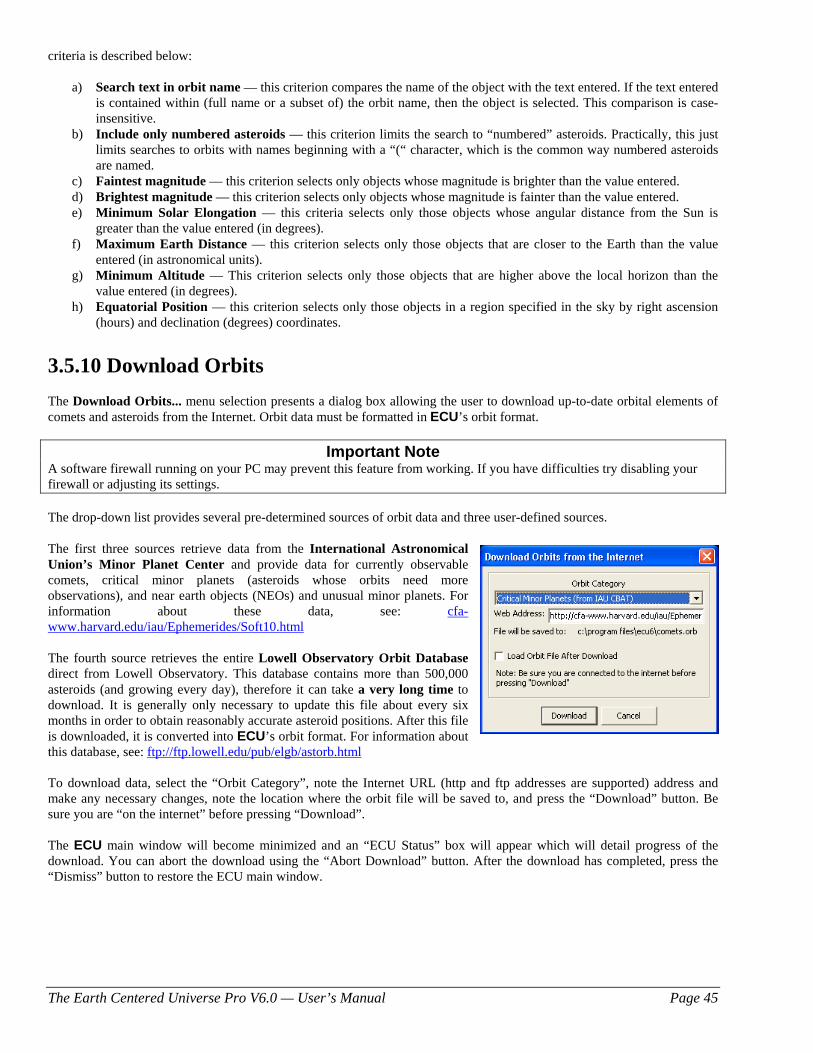
The Earth Centered Universe Pro V6.0 — User’s Manual Page 45
criteria is described below:
a) Search text in orbit name — this criterion compares the name of the object with the text entered. If the text entered is contained within (full name or a subset of) the orbit name, then the object is selected. This comparison is case-insensitive.
b) Include only numbered asteroids — this criterion limits the search to “numbered” asteroids. Practically, this just limits searches to orbits with names beginning with a “(“ character, which is the common way numbered asteroids are named.
c) Faintest magnitude — this criterion selects only objects whose magnitude is brighter than the value entered. d) Brightest magnitude — this criterion selects only objects whose magnitude is fainter than the value entered. e) Minimum Solar Elongation — this criteria selects only those objects whose angular distance from the Sun is
greater than the value entered (in degrees). f) Maximum Earth Distance — this criterion selects only those objects that are closer to the Earth than the value
entered (in astronomical units). g) Minimum Altitude — This criterion selects only those objects that are higher above the local horizon than the
value entered (in degrees). h) Equatorial Position — this criterion selects only those objects in a region specified in the sky by right ascension
(hours) and declination (degrees) coordinates.
3.5.10 Download Orbits The Download Orbits... menu selection presents a dialog box allowing the user to download up-to-date orbital elements of comets and asteroids from the Internet. Orbit data must be formatted in ECU’s orbit format.
Important Note A software firewall running on your PC may prevent this feature from working. If you have difficulties try disabling your firewall or adjusting its settings. The drop-down list provides several pre-determined sources of orbit data and three user-defined sources. The first three sources retrieve data from the International Astronomical Union’s Minor Planet Center and provide data for currently observable comets, critical minor planets (asteroids whose orbits need more observations), and near earth objects (NEOs) and unusual minor planets. For information about these data, see: cfa-www.harvard.edu/iau/Ephemerides/Soft10.html The fourth source retrieves the entire Lowell Observatory Orbit Database direct from Lowell Observatory. This database contains more than 500,000 asteroids (and growing every day), therefore it can take a very long time to download. It is generally only necessary to update this file about every six months in order to obtain reasonably accurate asteroid positions. After this file is downloaded, it is converted into ECU’s orbit format. For information about this database, see: ftp://ftp.lowell.edu/pub/elgb/astorb.html To download data, select the “Orbit Category”, note the Internet URL (http and ftp addresses are supported) address and make any necessary changes, note the location where the orbit file will be saved to, and press the “Download” button. Be sure you are “on the internet” before pressing “Download”. The ECU main window will become minimized and an “ECU Status” box will appear which will detail progress of the download. You can abort the download using the “Abort Download” button. After the download has completed, press the “Dismiss” button to restore the ECU main window.
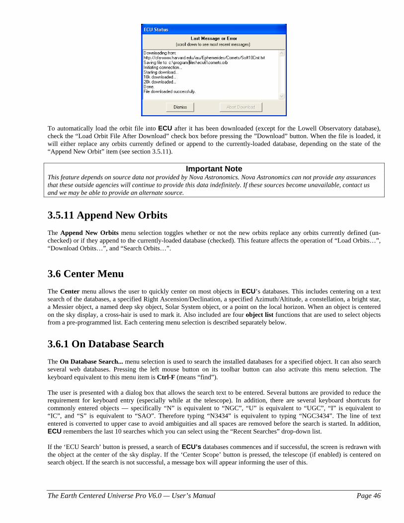
The Earth Centered Universe Pro V6.0 — User’s Manual Page 46
To automatically load the orbit file into ECU after it has been downloaded (except for the Lowell Observatory database), check the “Load Orbit File After Download” check box before pressing the ”Download” button. When the file is loaded, it will either replace any orbits currently defined or append to the currently-loaded database, depending on the state of the “Append New Orbit” item (see section 3.5.11).
Important Note This feature depends on source data not provided by Nova Astronomics. Nova Astronomics can not provide any assurances that these outside agencies will continue to provide this data indefinitely. If these sources become unavailable, contact us and we may be able to provide an alternate source.
3.5.11 Append New Orbits The Append New Orbits menu selection toggles whether or not the new orbits replace any orbits currently defined (un-checked) or if they append to the currently-loaded database (checked). This feature affects the operation of “Load Orbits…”, “Download Orbits…”, and “Search Orbits…”.
3.6 Center Menu The Center menu allows the user to quickly center on most objects in ECU’s databases. This includes centering on a text search of the databases, a specified Right Ascension/Declination, a specified Azimuth/Altitude, a constellation, a bright star, a Messier object, a named deep sky object, Solar System object, or a point on the local horizon. When an object is centered on the sky display, a cross-hair is used to mark it. Also included are four object list functions that are used to select objects from a pre-programmed list. Each centering menu selection is described separately below.
3.6.1 On Database Search The On Database Search... menu selection is used to search the installed databases for a specified object. It can also search several web databases. Pressing the left mouse button on its toolbar button can also activate this menu selection. The keyboard equivalent to this menu item is Ctrl-F (means “find”). The user is presented with a dialog box that allows the search text to be entered. Several buttons are provided to reduce the requirement for keyboard entry (especially while at the telescope). In addition, there are several keyboard shortcuts for commonly entered objects — specifically “N” is equivalent to “NGC”, “U” is equivalent to “UGC”, “I” is equivalent to “IC”, and “S” is equivalent to “SAO”. Therefore typing “N3434” is equivalent to typing “NGC3434”. The line of text entered is converted to upper case to avoid ambiguities and all spaces are removed before the search is started. In addition, ECU remembers the last 10 searches which you can select using the “Recent Searches” drop-down list. If the ‘ECU Search’ button is pressed, a search of ECU’s databases commences and if successful, the screen is redrawn with the object at the center of the sky display. If the ‘Center Scope’ button is pressed, the telescope (if enabled) is centered on search object. If the search is not successful, a message box will appear informing the user of this.
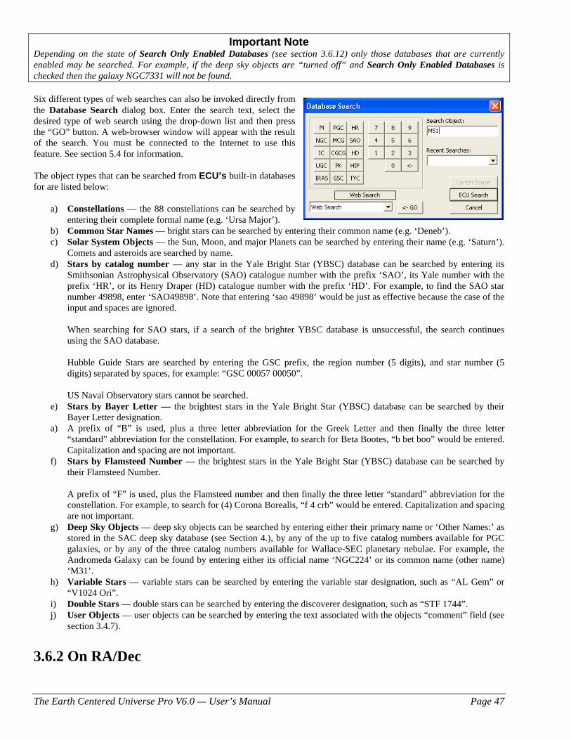
The Earth Centered Universe Pro V6.0 — User’s Manual Page 47
Important Note Depending on the state of Search Only Enabled Databases (see section 3.6.12) only those databases that are currently enabled may be searched. For example, if the deep sky objects are “turned off” and Search Only Enabled Databases is checked then the galaxy NGC7331 will not be found. Six different types of web searches can also be invoked directly from the Database Search dialog box. Enter the search text, select the desired type of web search using the drop-down list and then press the “GO” button. A web-browser window will appear with the result of the search. You must be connected to the Internet to use this feature. See section 5.4 for information. The object types that can be searched from ECU’s built-in databases for are listed below:
a) Constellations — the 88 constellations can be searched by entering their complete formal name (e.g. ‘Ursa Major’).
b) Common Star Names — bright stars can be searched by entering their common name (e.g. ‘Deneb’). c) Solar System Objects — the Sun, Moon, and major Planets can be searched by entering their name (e.g. ‘Saturn’).
Comets and asteroids are searched by name. d) Stars by catalog number — any star in the Yale Bright Star (YBSC) database can be searched by entering its
Smithsonian Astrophysical Observatory (SAO) catalogue number with the prefix ‘SAO’, its Yale number with the prefix ‘HR’, or its Henry Draper (HD) catalogue number with the prefix ‘HD’. For example, to find the SAO star number 49898, enter ‘SAO49898’. Note that entering ‘sao 49898’ would be just as effective because the case of the input and spaces are ignored.
When searching for SAO stars, if a search of the brighter YBSC database is unsuccessful, the search continues using the SAO database. Hubble Guide Stars are searched by entering the GSC prefix, the region number (5 digits), and star number (5 digits) separated by spaces, for example: “GSC 00057 00050”.
US Naval Observatory stars cannot be searched.
e) Stars by Bayer Letter — the brightest stars in the Yale Bright Star (YBSC) database can be searched by their Bayer Letter designation.
a) A prefix of “B” is used, plus a three letter abbreviation for the Greek Letter and then finally the three letter “standard” abbreviation for the constellation. For example, to search for Beta Bootes, “b bet boo” would be entered. Capitalization and spacing are not important.
f) Stars by Flamsteed Number — the brightest stars in the Yale Bright Star (YBSC) database can be searched by their Flamsteed Number.
A prefix of “F” is used, plus the Flamsteed number and then finally the three letter “standard” abbreviation for the constellation. For example, to search for (4) Corona Borealis, “f 4 crb” would be entered. Capitalization and spacing are not important.
g) Deep Sky Objects — deep sky objects can be searched by entering either their primary name or ‘Other Names:’ as stored in the SAC deep sky database (see Section 4.), by any of the up to five catalog numbers available for PGC galaxies, or by any of the three catalog numbers available for Wallace-SEC planetary nebulae. For example, the Andromeda Galaxy can be found by entering either its official name ‘NGC224’ or its common name (other name) ‘M31’.
h) Variable Stars — variable stars can be searched by entering the variable star designation, such as “AL Gem” or “V1024 Ori”.
i) Double Stars — double stars can be searched by entering the discoverer designation, such as “STF 1744”. j) User Objects — user objects can be searched by entering the text associated with the objects “comment” field (see
section 3.4.7).
3.6.2 On RA/Dec
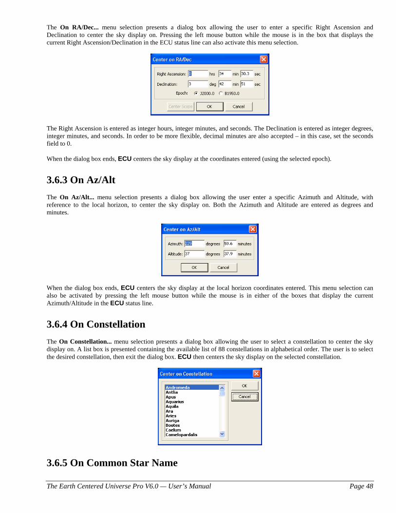
The Earth Centered Universe Pro V6.0 — User’s Manual Page 48
The On RA/Dec... menu selection presents a dialog box allowing the user to enter a specific Right Ascension and Declination to center the sky display on. Pressing the left mouse button while the mouse is in the box that displays the current Right Ascension/Declination in the ECU status line can also activate this menu selection.
The Right Ascension is entered as integer hours, integer minutes, and seconds. The Declination is entered as integer degrees, integer minutes, and seconds. In order to be more flexible, decimal minutes are also accepted – in this case, set the seconds field to 0. When the dialog box ends, ECU centers the sky display at the coordinates entered (using the selected epoch).
3.6.3 On Az/Alt The On Az/Alt... menu selection presents a dialog box allowing the user enter a specific Azimuth and Altitude, with reference to the local horizon, to center the sky display on. Both the Azimuth and Altitude are entered as degrees and minutes.
When the dialog box ends, ECU centers the sky display at the local horizon coordinates entered. This menu selection can also be activated by pressing the left mouse button while the mouse is in either of the boxes that display the current Azimuth/Altitude in the ECU status line.
3.6.4 On Constellation The On Constellation... menu selection presents a dialog box allowing the user to select a constellation to center the sky display on. A list box is presented containing the available list of 88 constellations in alphabetical order. The user is to select the desired constellation, then exit the dialog box. ECU then centers the sky display on the selected constellation.
3.6.5 On Common Star Name
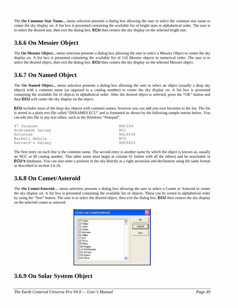
The Earth Centered Universe Pro V6.0 — User’s Manual Page 49
The On Common Star Name... menu selection presents a dialog box allowing the user to select the common star name to center the sky display on. A list box is presented containing the available list of bright stars in alphabetical order. The user is to select the desired star, then exit the dialog box. ECU then centers the sky display on the selected bright star.
3.6.6 On Messier Object The On Messier Object... menu selection presents a dialog box allowing the user to select a Messier Object to center the sky display on. A list box is presented containing the available list of 110 Messier objects in numerical order. The user is to select the desired object, then exit the dialog box. ECU then centers the sky display on the selected Messier object.
3.6.7 On Named Object The On Named Object... menu selection presents a dialog box allowing the user to select an object (usually a deep sky object) with a common name (as opposed to a catalog number) to center the sky display on. A list box is presented containing the available list of objects in alphabetical order. After the desired object is selected, press the “OK” button and then ECU will center the sky display on the object. ECU includes most of the deep sky objects with common names, however you can add you own favorites to the list. The list is stored in a plain text file called “DSNAMES.ECU” and is formatted as shown by the following sample entries below. You can edit this file in any text editor, such as the Windows “Notepad”. 47 Tucanae NGC104 Andromeda Galaxy M31 Antennae NGC4038 Barbell Nebula M76 Barnard’s Galaxy NGC6822 The first entry on each line is the common name. The second entry is another name by which the object is known as, usually an NGC or M catalog number. This other name must begin at column 41 (inline with all the others) and be searchable in ECU’s databases. You can also enter a position in the sky directly as a right ascension and declination using the same format as described in section 3.6.16.
3.6.8 On Comet/Asteroid The On Comet/Asteroid… menu selection presents a dialog box allowing the user to select a Comet or Asteroid to center the sky display on. A list box is presented containing the available list of objects. These can be sorted in alphabetical order by using the “Sort” button. The user is to select the desired object, then exit the dialog box. ECU then centers the sky display on the selected comet or asteroid.
3.6.9 On Solar System Object
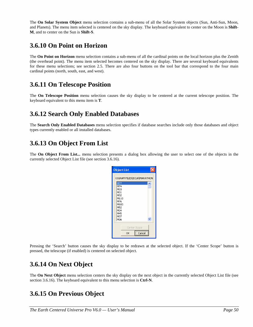
The Earth Centered Universe Pro V6.0 — User’s Manual Page 50
The On Solar System Object menu selection contains a sub-menu of all the Solar System objects (Sun, Anti-Sun, Moon, and Planets). The menu item selected is centered on the sky display. The keyboard equivalent to center on the Moon is Shift-M, and to center on the Sun is Shift-S.
3.6.10 On Point on Horizon The On Point on Horizon menu selection contains a sub-menu of all the cardinal points on the local horizon plus the Zenith (the overhead point). The menu item selected becomes centered on the sky display. There are several keyboard equivalents for these menu selections; see section 2.5. There are also four buttons on the tool bar that correspond to the four main cardinal points (north, south, east, and west).
3.6.11 On Telescope Position The On Telescope Position menu selection causes the sky display to be centered at the current telescope position. The keyboard equivalent to this menu item is T.
3.6.12 Search Only Enabled Databases The Search Only Enabled Databases menu selection specifies if database searches include only those databases and object types currently enabled or all installed databases.
3.6.13 On Object From List The On Object From List... menu selection presents a dialog box allowing the user to select one of the objects in the currently selected Object List file (see section 3.6.16).
Pressing the ‘Search’ button causes the sky display to be redrawn at the selected object. If the ‘Center Scope’ button is pressed, the telescope (if enabled) is centered on selected object.
3.6.14 On Next Object The On Next Object menu selection centers the sky display on the next object in the currently selected Object List file (see section 3.6.16). The keyboard equivalent to this menu selection is Ctrl-N.
3.6.15 On Previous Object
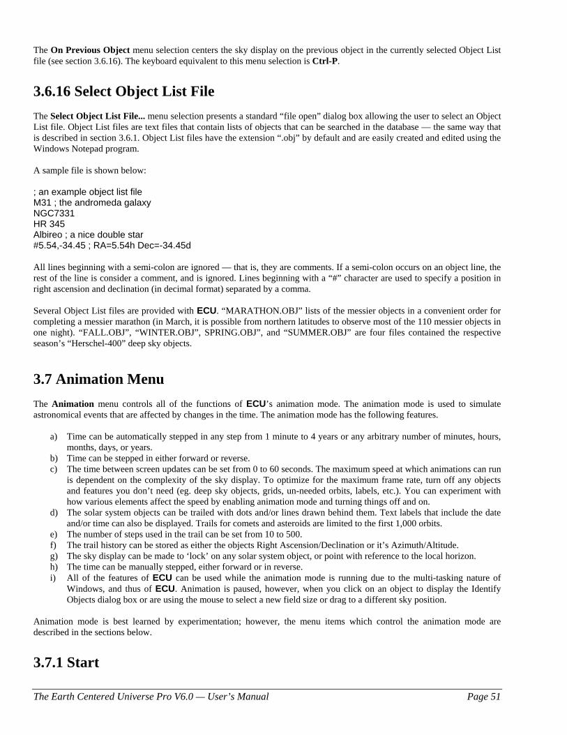
The Earth Centered Universe Pro V6.0 — User’s Manual Page 51
The On Previous Object menu selection centers the sky display on the previous object in the currently selected Object List file (see section 3.6.16). The keyboard equivalent to this menu selection is Ctrl-P.
3.6.16 Select Object List File The Select Object List File... menu selection presents a standard “file open” dialog box allowing the user to select an Object List file. Object List files are text files that contain lists of objects that can be searched in the database — the same way that is described in section 3.6.1. Object List files have the extension “.obj” by default and are easily created and edited using the Windows Notepad program. A sample file is shown below: ; an example object list file M31 ; the andromeda galaxy NGC7331 HR 345 Albireo ; a nice double star #5.54,-34.45 ; RA=5.54h Dec=-34.45d All lines beginning with a semi-colon are ignored — that is, they are comments. If a semi-colon occurs on an object line, the rest of the line is consider a comment, and is ignored. Lines beginning with a “#” character are used to specify a position in right ascension and declination (in decimal format) separated by a comma. Several Object List files are provided with ECU. “MARATHON.OBJ” lists of the messier objects in a convenient order for completing a messier marathon (in March, it is possible from northern latitudes to observe most of the 110 messier objects in one night). “FALL.OBJ”, “WINTER.OBJ”, SPRING.OBJ”, and “SUMMER.OBJ” are four files contained the respective season’s “Herschel-400” deep sky objects.
3.7 Animation Menu The Animation menu controls all of the functions of ECU’s animation mode. The animation mode is used to simulate astronomical events that are affected by changes in the time. The animation mode has the following features.
a) Time can be automatically stepped in any step from 1 minute to 4 years or any arbitrary number of minutes, hours, months, days, or years.
b) Time can be stepped in either forward or reverse. c) The time between screen updates can be set from 0 to 60 seconds. The maximum speed at which animations can run
is dependent on the complexity of the sky display. To optimize for the maximum frame rate, turn off any objects and features you don’t need (eg. deep sky objects, grids, un-needed orbits, labels, etc.). You can experiment with how various elements affect the speed by enabling animation mode and turning things off and on.
d) The solar system objects can be trailed with dots and/or lines drawn behind them. Text labels that include the date and/or time can also be displayed. Trails for comets and asteroids are limited to the first 1,000 orbits.
e) The number of steps used in the trail can be set from 10 to 500. f) The trail history can be stored as either the objects Right Ascension/Declination or it’s Azimuth/Altitude. g) The sky display can be made to ‘lock’ on any solar system object, or point with reference to the local horizon. h) The time can be manually stepped, either forward or in reverse. i) All of the features of ECU can be used while the animation mode is running due to the multi-tasking nature of
Windows, and thus of ECU. Animation is paused, however, when you click on an object to display the Identify Objects dialog box or are using the mouse to select a new field size or drag to a different sky position.
Animation mode is best learned by experimentation; however, the menu items which control the animation mode are described in the sections below.
3.7.1 Start
The Earth Centered Universe Pro V6.0 — User’s Manual Page 52
The Start menu selection starts the animation mode. If a ‘check mark’ precedes the menu selection, animation mode is running. Animation mode can also be started and stopped using the corresponding tool bar button.
3.7.2 Stop The Stop menu selection stops the animation mode. The ESC key can also be used to stop the animation mode. Animation mode can also be started and stopped using the corresponding tool bar button.
3.7.3 Forward One Step The Forward One Step menu selection steps the time forward by one time step. The time step is displayed to the left of the time step buttons in the status area. This menu selection can also be executed by using the toolbar button or by pressing the ‘+’ key.
3.7.4 Reverse One Step The Reverse One Step menu selection steps the time in reverse by one time step. The time step is displayed to the left of the time step buttons in the status area. This menu selection can also be executed by using the toolbar button or by pressing the ‘-’ key.
3.7.5 Restore Date/Time The Restore Date/Time menu selection restore the date and time to what it was prior to the last time the animation mode was started or the last time this menu item was selected. This feature is useful for experimenting with the animation mode without having to keep resetting the time back manually again and again.
3.7.6 Trails On The Trails On menu selection enables the drawing of trails (small crosses) behind the Solar System objects. If the trails are enabled, a ‘check mark’ will precede this menu selection.
3.7.7 Trail Lines On The Trails Lines On menu selection enables the drawing of trail lines behind the Solar System objects. If the trail lines are enabled, a ‘check mark’ will precede this menu selection.
3.7.8 Clear Trails The Clear Trails menu selection clears the current trail history and removes any existing trail crosses or lines drawn behind Solar System objects from the sky display.
3.7.9 Trail Settings The Trail Settings... menu selection presents a dialog box allowing the user to control a number of parameters pertaining to the trail crosses and trail lines drawn behind Solar System Objects.
The following items are included in this dialog box:
a) Number of Trails — sets the maximum number of trail crosses and/or trail lines.
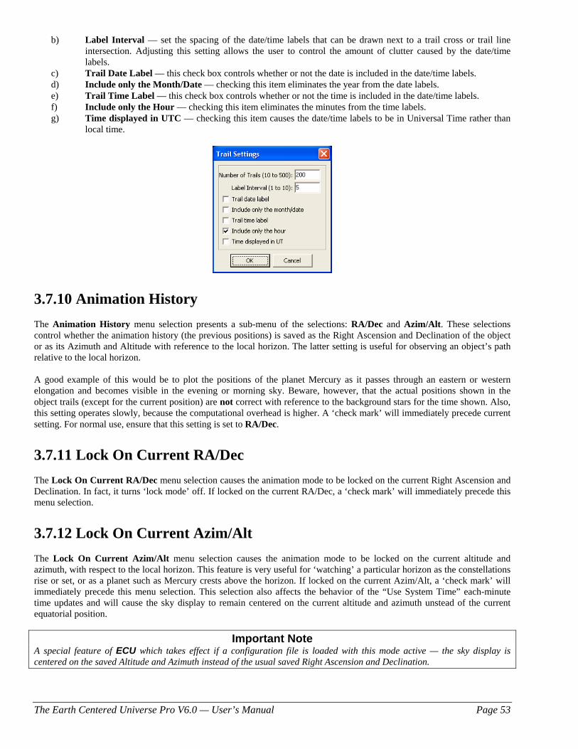
The Earth Centered Universe Pro V6.0 — User’s Manual Page 53
b) Label Interval — set the spacing of the date/time labels that can be drawn next to a trail cross or trail line intersection. Adjusting this setting allows the user to control the amount of clutter caused by the date/time labels.
c) Trail Date Label — this check box controls whether or not the date is included in the date/time labels. d) Include only the Month/Date — checking this item eliminates the year from the date labels. e) Trail Time Label — this check box controls whether or not the time is included in the date/time labels. f) Include only the Hour — checking this item eliminates the minutes from the time labels. g) Time displayed in UTC — checking this item causes the date/time labels to be in Universal Time rather than
local time.
3.7.10 Animation History The Animation History menu selection presents a sub-menu of the selections: RA/Dec and Azim/Alt. These selections control whether the animation history (the previous positions) is saved as the Right Ascension and Declination of the object or as its Azimuth and Altitude with reference to the local horizon. The latter setting is useful for observing an object’s path relative to the local horizon. A good example of this would be to plot the positions of the planet Mercury as it passes through an eastern or western elongation and becomes visible in the evening or morning sky. Beware, however, that the actual positions shown in the object trails (except for the current position) are not correct with reference to the background stars for the time shown. Also, this setting operates slowly, because the computational overhead is higher. A ‘check mark’ will immediately precede current setting. For normal use, ensure that this setting is set to RA/Dec.
3.7.11 Lock On Current RA/Dec The Lock On Current RA/Dec menu selection causes the animation mode to be locked on the current Right Ascension and Declination. In fact, it turns ‘lock mode’ off. If locked on the current RA/Dec, a ‘check mark’ will immediately precede this menu selection.
3.7.12 Lock On Current Azim/Alt The Lock On Current Azim/Alt menu selection causes the animation mode to be locked on the current altitude and azimuth, with respect to the local horizon. This feature is very useful for ‘watching’ a particular horizon as the constellations rise or set, or as a planet such as Mercury crests above the horizon. If locked on the current Azim/Alt, a ‘check mark’ will immediately precede this menu selection. This selection also affects the behavior of the “Use System Time” each-minute time updates and will cause the sky display to remain centered on the current altitude and azimuth unstead of the current equatorial position.
Important Note A special feature of ECU which takes effect if a configuration file is loaded with this mode active — the sky display is centered on the saved Altitude and Azimuth instead of the usual saved Right Ascension and Declination.
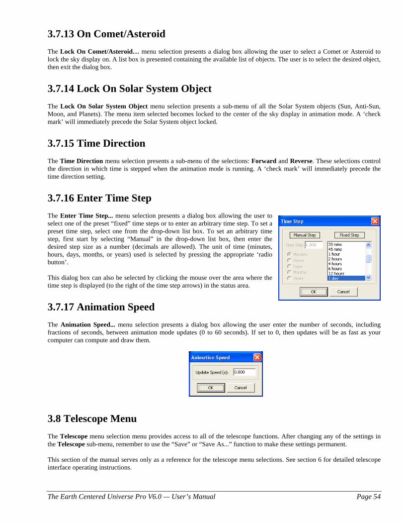
The Earth Centered Universe Pro V6.0 — User’s Manual Page 54
3.7.13 On Comet/Asteroid The Lock On Comet/Asteroid… menu selection presents a dialog box allowing the user to select a Comet or Asteroid to lock the sky display on. A list box is presented containing the available list of objects. The user is to select the desired object, then exit the dialog box.
3.7.14 Lock On Solar System Object The Lock On Solar System Object menu selection presents a sub-menu of all the Solar System objects (Sun, Anti-Sun, Moon, and Planets). The menu item selected becomes locked to the center of the sky display in animation mode. A ‘check mark’ will immediately precede the Solar System object locked.
3.7.15 Time Direction The Time Direction menu selection presents a sub-menu of the selections: Forward and Reverse. These selections control the direction in which time is stepped when the animation mode is running. A ‘check mark’ will immediately precede the time direction setting.
3.7.16 Enter Time Step The Enter Time Step... menu selection presents a dialog box allowing the user to select one of the preset “fixed” time steps or to enter an arbitrary time step. To set a preset time step, select one from the drop-down list box. To set an arbitrary time step, first start by selecting “Manual” in the drop-down list box, then enter the desired step size as a number (decimals are allowed). The unit of time (minutes, hours, days, months, or years) used is selected by pressing the appropriate ‘radio button’. This dialog box can also be selected by clicking the mouse over the area where the time step is displayed (to the right of the time step arrows) in the status area.
3.7.17 Animation Speed The Animation Speed... menu selection presents a dialog box allowing the user enter the number of seconds, including fractions of seconds, between animation mode updates (0 to 60 seconds). If set to 0, then updates will be as fast as your computer can compute and draw them.
3.8 Telescope Menu The Telescope menu selection menu provides access to all of the telescope functions. After changing any of the settings in the Telescope sub-menu, remember to use the “Save” or “Save As...” function to make these settings permanent. This section of the manual serves only as a reference for the telescope menu selections. See section 6 for detailed telescope interface operating instructions.
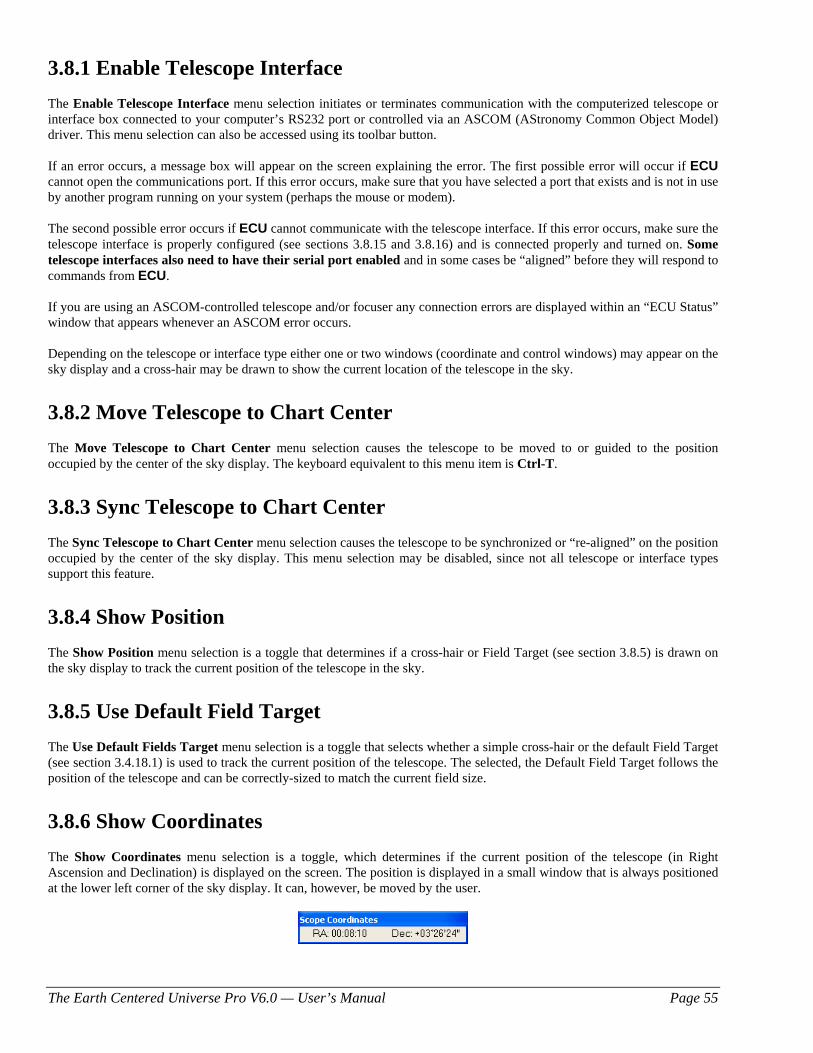
The Earth Centered Universe Pro V6.0 — User’s Manual Page 55
3.8.1 Enable Telescope Interface The Enable Telescope Interface menu selection initiates or terminates communication with the computerized telescope or interface box connected to your computer’s RS232 port or controlled via an ASCOM (AStronomy Common Object Model) driver. This menu selection can also be accessed using its toolbar button. If an error occurs, a message box will appear on the screen explaining the error. The first possible error will occur if ECU cannot open the communications port. If this error occurs, make sure that you have selected a port that exists and is not in use by another program running on your system (perhaps the mouse or modem). The second possible error occurs if ECU cannot communicate with the telescope interface. If this error occurs, make sure the telescope interface is properly configured (see sections 3.8.15 and 3.8.16) and is connected properly and turned on. Some telescope interfaces also need to have their serial port enabled and in some cases be “aligned” before they will respond to commands from ECU. If you are using an ASCOM-controlled telescope and/or focuser any connection errors are displayed within an “ECU Status” window that appears whenever an ASCOM error occurs. Depending on the telescope or interface type either one or two windows (coordinate and control windows) may appear on the sky display and a cross-hair may be drawn to show the current location of the telescope in the sky.
3.8.2 Move Telescope to Chart Center The Move Telescope to Chart Center menu selection causes the telescope to be moved to or guided to the position occupied by the center of the sky display. The keyboard equivalent to this menu item is Ctrl-T.
3.8.3 Sync Telescope to Chart Center The Sync Telescope to Chart Center menu selection causes the telescope to be synchronized or “re-aligned” on the position occupied by the center of the sky display. This menu selection may be disabled, since not all telescope or interface types support this feature.
3.8.4 Show Position The Show Position menu selection is a toggle that determines if a cross-hair or Field Target (see section 3.8.5) is drawn on the sky display to track the current position of the telescope in the sky.
3.8.5 Use Default Field Target The Use Default Fields Target menu selection is a toggle that selects whether a simple cross-hair or the default Field Target (see section 3.4.18.1) is used to track the current position of the telescope. The selected, the Default Field Target follows the position of the telescope and can be correctly-sized to match the current field size.
3.8.6 Show Coordinates The Show Coordinates menu selection is a toggle, which determines if the current position of the telescope (in Right Ascension and Declination) is displayed on the screen. The position is displayed in a small window that is always positioned at the lower left corner of the sky display. It can, however, be moved by the user.
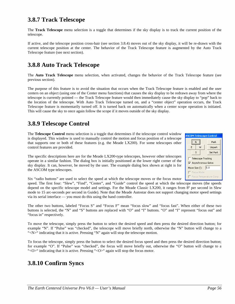
The Earth Centered Universe Pro V6.0 — User’s Manual Page 56
3.8.7 Track Telescope The Track Telescope menu selection is a toggle that determines if the sky display is to track the current position of the telescope. If active, and the telescope position cross-hair (see section 3.8.4) moves out of the sky display, it will be re-drawn with the current telescope position at the center. The behavior of the Track Telescope feature is augmented by the Auto Track Telescope feature (see next section).
3.8.8 Auto Track Telescope The Auto Track Telescope menu selection, when activated, changes the behavior of the Track Telescope feature (see previous section). The purpose of this feature is to avoid the situation that occurs when the Track Telescope feature is enabled and the user centers on an object (using one of the Center menu functions) that causes the sky display to be redrawn away from where the telescope is currently pointed — the Track Telescope feature would then immediately cause the sky display to “pop” back to the location of the telescope. With Auto Track Telescope turned on, and a “center object” operation occurs, the Track Telescope feature is momentarily turned off. It is turned back on automatically when a center scope operation is initiated. This will cause the sky to once again follow the scope if it moves outside of the sky display.
3.8.9 Telescope Control The Telescope Control menu selection is a toggle that determines if the telescope control window is displayed. This window is used to manually control the motion and focus position of a telescope that supports one or both of these features (e.g. the Meade LX200). For some telescopes other control features are provided. The specific descriptions here are for the Meade LX200-type telescopes, however other telescopes operate in a similar fashion. The dialog box is initially positioned at the lower right corner of the sky display. It can, however, be moved by the user. The example dialog box shown at right is for the ASCOM type telescopes. Six “radio buttons” are used to select the speed at which the telescope moves or the focus motor speed. The first four: “Slew”, “Find”, “Center”, and “Guide” control the speed at which the telescope moves (the speeds depend on the specific telescope model and settings. For the Meade Classic LX200, it ranges from 8º per second in Slew mode to 15 arc-seconds per second in Guide). Note that the Meade Autostar does not support changing motor speed settings via its serial interface — you must do this using the hand controller. The other two buttons, labeled “Focus S” and “Focus F” mean “focus slow” and “focus fast”. When either of these two buttons is selected, the “N” and “S” buttons are replaced with “O” and “I” buttons. “O” and “I” represent “focus out” and “focus in” respectively. To move the telescope, simply press the button to select the desired speed and then press the desired direction button; for example “N”. If “Pulse” was “checked”, the telescope will move briefly north, otherwise the “N” button will change to a “<N>“ indicating that it is active. Pressing “N” again will stop the telescope motion. To focus the telescope, simply press the button to select the desired focus speed and then press the desired direction button; for example “O”. If “Pulse” was “checked”, the focus will move briefly out, otherwise the “O” button will change to a “<O>“ indicating that it is active. Pressing “<O>“ again will stop the focus motor.
3.8.10 Confirm Syncs
The Earth Centered Universe Pro V6.0 — User’s Manual Page 57
The Confirm Syncs menu selection is a toggle that determines if the user is prompted to confirm telescope sync operations. This makes it less likely that you will accidently sync your telescope on the wrong object or location.
3.8.11 Set Telescope Time The Set Telescope Time menu selection sets the time used by many telescopes, including Meade LX200s, LXD mounts, Autostar-based telescopes, Losmandy Gemini, and the Astro-Physics GTO mount, to the current time as provided by your PC’s clock. If you use this function, make sure that the PC’s time has been set very accurately; otherwise telescope positioning accuracy may be degraded. Note that with the Astro-Physics GTO mount, ECU sets the time automatically as part if its initialization.
3.8.12 Set Telescope Geographic Location The Set Telescope Geographic Location menu selection sets the geographic location used by many telescopes, including Meade LX200s, Meade LXD mounts, Autostar-based telescopes, Losmandy Gemini, and the Astro-Physics GTO mount, to that currently set in ECU. Note that with the Astro-Physics GTO mount, ECU sets the location automatically as part if its initialization. Note that if this function generates an error with the Meade Autostar telescope, this is a sign that the firmware in your Autostar should be upgraded (see the Meade website for details on how to do this).
3.8.13 Set Encoder Interface Resolution The Set Encoder Interface Resolution menu selection is used to “program” the number of counts per revolution for each optical encoder into the encoder interface. This procedure only needs be carried out once and is only necessary when using a JMI SGT-MAX (firmware version of 1.70 or later) or an Orion Sky Wizard CTI encoder interface. Both the SGT-MAX and CTI are essentially the same device, however they act differently depending on their firmware version. You may have to open the device to determine the version number — it is written on the label of the largest “chip.” For versions of the SGT-MAX earlier than V2.00, you should select “JMI SGT-MAX (before V2.00)” as the telescope interface type in “Telescope Type and General Settings” (see section 3.8.15). For versions 2.00 and later and all versions of the Orion CTI, select “Orion CTI & JMI SGT-MAX (V2.00 and later).” Before selecting this menu item, enter the actual encoder resolutions for each telescope axis (altitude=declination and azimuth=right ascension) into the dialog box provided by the menu item Encoder Interface Settings (see section 3.8.16) and press “OK”. Then select this menu item to “program” the encoder interface. If an error message is displayed, check your connections and make sure the encoder interface is turned on. When using a version of the SGT-MAX earlier than V2.00 only, continue by entering the values “32768” for both resolution entries in the menu item Encoder Interface Settings and press “OK”. This older version of the SGT-MAX automatically “scales” the encoder values up to 32768.
3.8.14 Select Alignment Stars The Select Alignment Stars menu selection provides a sub-menu allowing up to two alignment stars, used by the optical encoder interface system, to be selected. The menus themselves show the currently selected alignment stars. Alignment “stars” can be chosen from any object in ECU’s databases. Usually stars are used to align the optical encoder system, however it is possible align the system using the Sun, Moon, and/or planets in the daytime, but if you do this, you have to select the Sun, Moon, and/or planets as alignment “stars” immediately before doing the alignment. This is because their positions are what are saved, and these positions change with time. To select an alignment star, “click” on the desired object. With its Identify Object dialog box displayed, select either 1st Alignment Star or 2nd Alignment Star menu items.
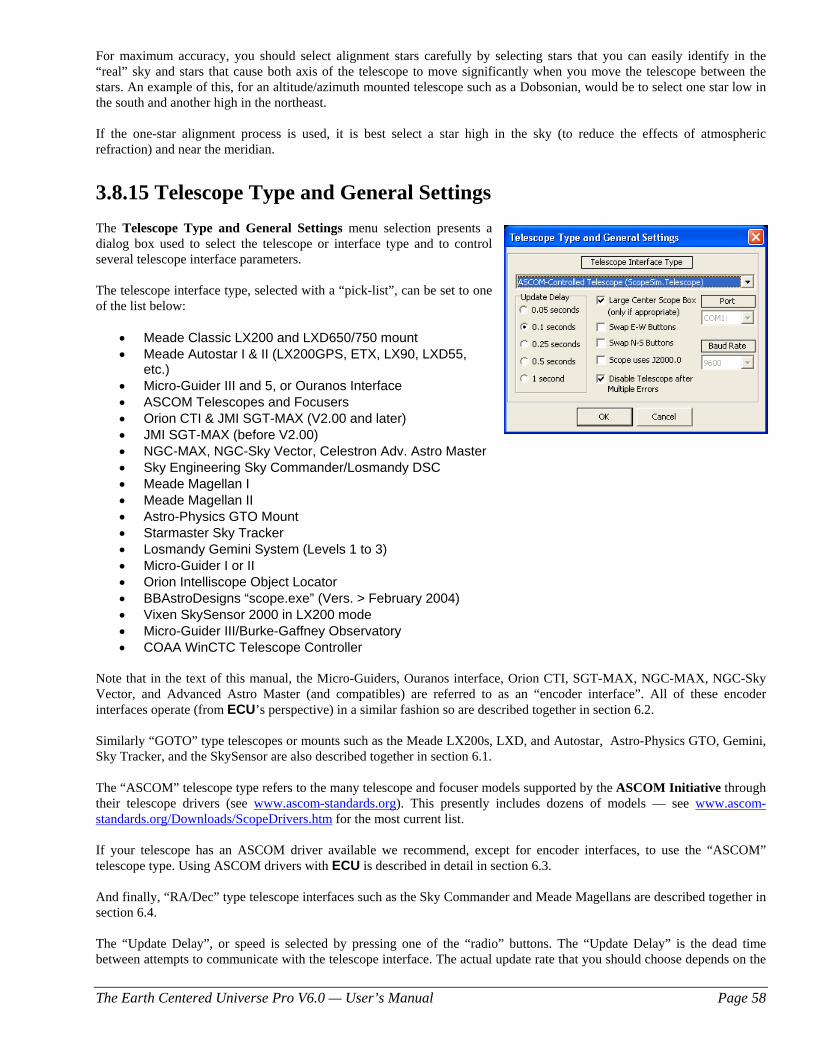
The Earth Centered Universe Pro V6.0 — User’s Manual Page 58
For maximum accuracy, you should select alignment stars carefully by selecting stars that you can easily identify in the “real” sky and stars that cause both axis of the telescope to move significantly when you move the telescope between the stars. An example of this, for an altitude/azimuth mounted telescope such as a Dobsonian, would be to select one star low in the south and another high in the northeast. If the one-star alignment process is used, it is best select a star high in the sky (to reduce the effects of atmospheric refraction) and near the meridian.
3.8.15 Telescope Type and General Settings The Telescope Type and General Settings menu selection presents a dialog box used to select the telescope or interface type and to control several telescope interface parameters. The telescope interface type, selected with a “pick-list”, can be set to one of the list below:
• Meade Classic LX200 and LXD650/750 mount • Meade Autostar I & II (LX200GPS, ETX, LX90, LXD55,
etc.) • Micro-Guider III and 5, or Ouranos Interface • ASCOM Telescopes and Focusers • Orion CTI & JMI SGT-MAX (V2.00 and later) • JMI SGT-MAX (before V2.00) • NGC-MAX, NGC-Sky Vector, Celestron Adv. Astro Master • Sky Engineering Sky Commander/Losmandy DSC • Meade Magellan I • Meade Magellan II • Astro-Physics GTO Mount • Starmaster Sky Tracker • Losmandy Gemini System (Levels 1 to 3) • Micro-Guider I or II • Orion Intelliscope Object Locator • BBAstroDesigns “scope.exe” (Vers. > February 2004) • Vixen SkySensor 2000 in LX200 mode • Micro-Guider III/Burke-Gaffney Observatory • COAA WinCTC Telescope Controller
Note that in the text of this manual, the Micro-Guiders, Ouranos interface, Orion CTI, SGT-MAX, NGC-MAX, NGC-Sky Vector, and Advanced Astro Master (and compatibles) are referred to as an “encoder interface”. All of these encoder interfaces operate (from ECU’s perspective) in a similar fashion so are described together in section 6.2. Similarly “GOTO” type telescopes or mounts such as the Meade LX200s, LXD, and Autostar, Astro-Physics GTO, Gemini, Sky Tracker, and the SkySensor are also described together in section 6.1. The “ASCOM” telescope type refers to the many telescope and focuser models supported by the ASCOM Initiative through their telescope drivers (see www.ascom-standards.org). This presently includes dozens of models — see www.ascom-standards.org/Downloads/ScopeDrivers.htm for the most current list. If your telescope has an ASCOM driver available we recommend, except for encoder interfaces, to use the “ASCOM” telescope type. Using ASCOM drivers with ECU is described in detail in section 6.3. And finally, “RA/Dec” type telescope interfaces such as the Sky Commander and Meade Magellans are described together in section 6.4. The “Update Delay”, or speed is selected by pressing one of the “radio” buttons. The “Update Delay” is the dead time between attempts to communicate with the telescope interface. The actual update rate that you should choose depends on the
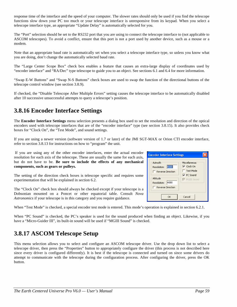
The Earth Centered Universe Pro V6.0 — User’s Manual Page 59
response time of the interface and the speed of your computer. The slower rates should only be used if you find the telescope functions slow down your PC too much or your telescope interface is unresponsive from its keypad. When you select a telescope interface type, an appropriate “Update Delay” is automatically selected for you. The “Port” selection should be set to the RS232 port that you are using to connect the telescope interface to (not applicable to ASCOM telescopes). To avoid a conflict, ensure that this port is not a port used by another device, such as a mouse or a modem. Note that an appropriate baud rate is automatically set when you select a telescope interface type, so unless you know what you are doing, don’t change the automatically selected baud rate. The “Large Center Scope Box” check box enables a feature that causes an extra-large display of coordinates used by “encoder interface” and “RA/Dec” type telescope to guide you to an object. See sections 6.1 and 6.4 for more information. “Swap E-W Buttons” and “Swap N-S Buttons” check boxes are used to swap the function of the directional buttons of the telescope control window (see section 3.8.9). If checked, the “Disable Telescope After Multiple Errors” setting causes the telescope interface to be automatically disabled after 10 successive unsuccessful attempts to query a telescope’s position.
3.8.16 Encoder Interface Settings The Encoder Interface Settings menu selection presents a dialog box used to set the resolution and direction of the optical encoders used with telescope interfaces that are of the “encoder interface” type (see section 3.8.15). It also provides check boxes for “Clock On”, the “Test Mode”, and sound settings. If you are using a newer version (software version of 1.7 or later) of the JMI SGT-MAX or Orion CTI encoder interface, refer to section 3.8.13 for instructions on how to “program” the unit. If you are using any of the other encoder interfaces, enter the actual encoder resolution for each axis of the telescope. These are usually the same for each axis, but do not have to be. Be sure to include the effects of any mechanical components, such as gears or pulleys. The setting of the direction check boxes is telescope specific and requires some experimentation that will be explained in section 6.2. The “Clock On” check box should always be checked except if your telescope is a Dobsonian mounted on a Poncet or other equatorial table. Consult Nova Astronomics if your telescope is in this category and you require guidance. When “Test Mode” is checked, a special encoder test mode is entered. This mode’s operation is explained in section 6.2.1. When “PC Sound” is checked, the PC’s speaker is used for the sound produced when finding an object. Likewise, if you have a “Micro-Guider III”, its built-in sound will be used if “MGIII Sound” is checked.
3.8.17 ASCOM Telescope Setup This menu selection allows you to select and configure an ASCOM telescope driver. Use the drop down list to select a telescope driver, then press the “Properties” button to appropriately configure the driver (this process is not described here since every driver is configured differently). It is best if the telescope is connected and turned on since some drivers do attempt to communicate with the telescope during the configuration process. After configuring the driver, press the OK button.
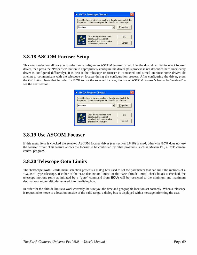
The Earth Centered Universe Pro V6.0 — User’s Manual Page 60
3.8.18 ASCOM Focuser Setup This menu selection allows you to select and configure an ASCOM focuser driver. Use the drop down list to select focuser driver, then press the “Properties” button to appropriately configure the driver (this process is not described here since every driver is configured differently). It is best if the telescope or focuser is connected and turned on since some drivers do attempt to communicate with the telescope or focuser during the configuration process. After configuring the driver, press the OK button. Note that in order for ECU to use the selected focuser, the use of ASCOM focuser’s has to be “enabled” – see the next section.
3.8.19 Use ASCOM Focuser If this menu item is checked the selected ASCOM focuser driver (see section 3.8.18) is used, otherwise ECU does not use the focuser driver. This feature allows the focuser to be controlled by other programs, such as MaxIm DL, a CCD camera control program.
3.8.20 Telescope Goto Limits The Telescope Goto Limits menu selection presents a dialog box used to set the parameters that can limit the motions of a “GOTO” Type telescope. If either of the “Use declination limits” or the “Use altitude limits” check boxes is checked, the telescope motions (only as initiated by a “goto” command from ECU) will be restricted to the minimum and maximum declinations and/or altitudes entered into the dialog box.
In order for the altitude limits to work correctly, be sure you the time and geographic location set correctly. When a telescope is requested to move to a location outside of the valid range, a dialog box is displayed with a message informing the user.
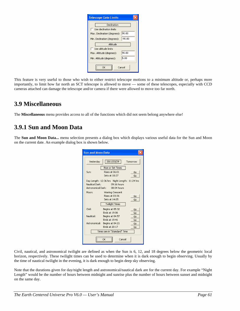
The Earth Centered Universe Pro V6.0 — User’s Manual Page 61
This feature is very useful to those who wish to either restrict telescope motions to a minimum altitude or, perhaps more importantly, to limit how far north an SCT telescope is allowed to move — some of these telescopes, especially with CCD cameras attached can damage the telescope and/or camera if there were allowed to move too far north.
3.9 Miscellaneous The Miscellaneous menu provides access to all of the functions which did not seem belong anywhere else!
3.9.1 Sun and Moon Data The Sun and Moon Data... menu selection presents a dialog box which displays various useful data for the Sun and Moon on the current date. An example dialog box is shown below.
Civil, nautical, and astronomical twilight are defined as when the Sun is 6, 12, and 18 degrees below the geometric local horizon, respectively. These twilight times can be used to determine when it is dark enough to begin observing. Usually by the time of nautical twilight in the evening, it is dark enough to begin deep sky observing. Note that the durations given for day/night length and astronomical/nautical dark are for the current day. For example “Night Length” would be the number of hours between midnight and sunrise plus the number of hours between sunset and midnight on the same day.
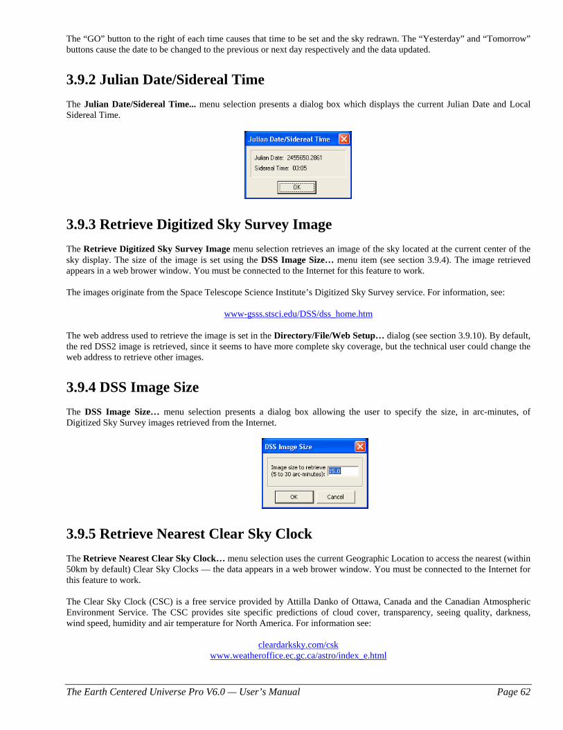
The Earth Centered Universe Pro V6.0 — User’s Manual Page 62
The “GO” button to the right of each time causes that time to be set and the sky redrawn. The “Yesterday” and “Tomorrow” buttons cause the date to be changed to the previous or next day respectively and the data updated.
3.9.2 Julian Date/Sidereal Time The Julian Date/Sidereal Time... menu selection presents a dialog box which displays the current Julian Date and Local Sidereal Time.
3.9.3 Retrieve Digitized Sky Survey Image The Retrieve Digitized Sky Survey Image menu selection retrieves an image of the sky located at the current center of the sky display. The size of the image is set using the DSS Image Size… menu item (see section 3.9.4). The image retrieved appears in a web brower window. You must be connected to the Internet for this feature to work. The images originate from the Space Telescope Science Institute’s Digitized Sky Survey service. For information, see:
www-gsss.stsci.edu/DSS/dss_home.htm The web address used to retrieve the image is set in the Directory/File/Web Setup… dialog (see section 3.9.10). By default, the red DSS2 image is retrieved, since it seems to have more complete sky coverage, but the technical user could change the web address to retrieve other images.
3.9.4 DSS Image Size The DSS Image Size… menu selection presents a dialog box allowing the user to specify the size, in arc-minutes, of Digitized Sky Survey images retrieved from the Internet.
3.9.5 Retrieve Nearest Clear Sky Clock The Retrieve Nearest Clear Sky Clock… menu selection uses the current Geographic Location to access the nearest (within 50km by default) Clear Sky Clocks — the data appears in a web brower window. You must be connected to the Internet for this feature to work. The Clear Sky Clock (CSC) is a free service provided by Attilla Danko of Ottawa, Canada and the Canadian Atmospheric Environment Service. The CSC provides site specific predictions of cloud cover, transparency, seeing quality, darkness, wind speed, humidity and air temperature for North America. For information see:
cleardarksky.com/csk www.weatheroffice.ec.gc.ca/astro/index_e.html
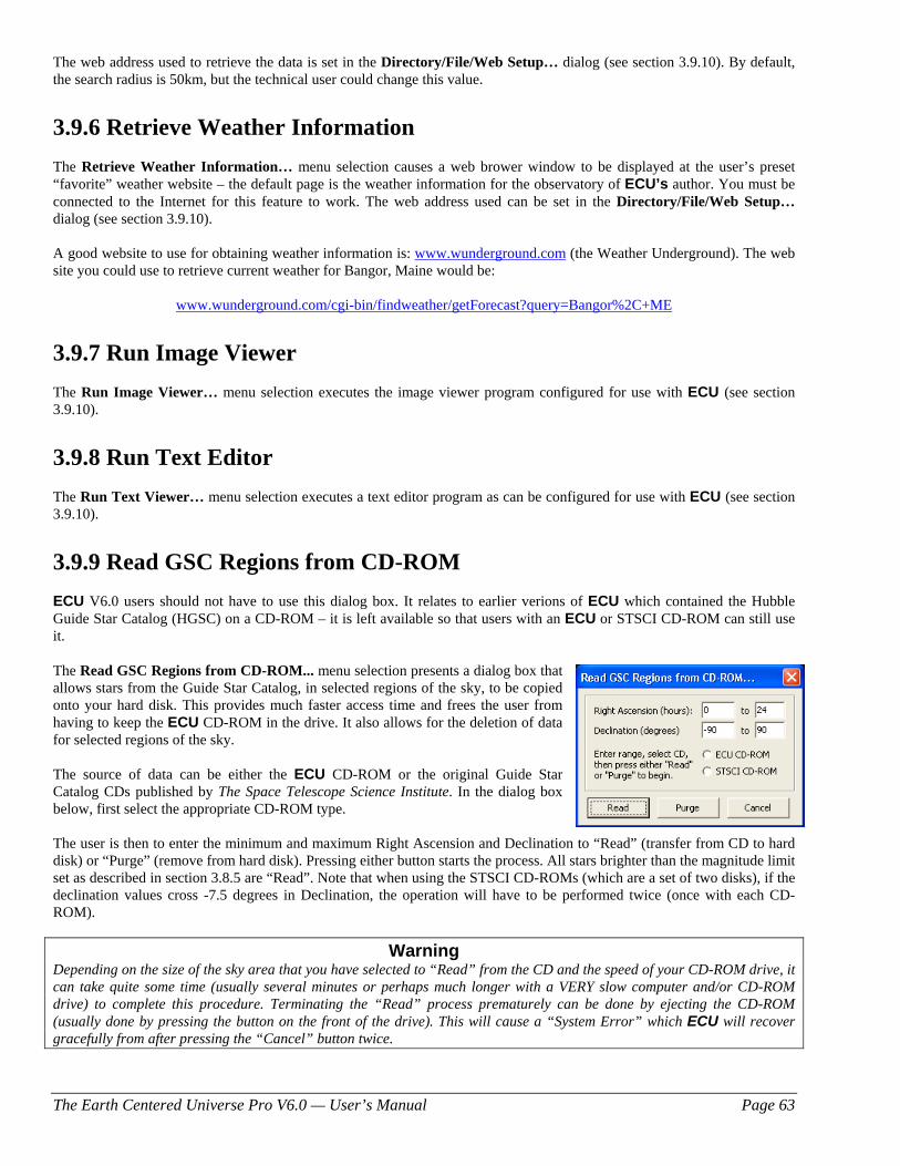
The Earth Centered Universe Pro V6.0 — User’s Manual Page 63
The web address used to retrieve the data is set in the Directory/File/Web Setup… dialog (see section 3.9.10). By default, the search radius is 50km, but the technical user could change this value.
3.9.6 Retrieve Weather Information The Retrieve Weather Information… menu selection causes a web brower window to be displayed at the user’s preset “favorite” weather website – the default page is the weather information for the observatory of ECU’s author. You must be connected to the Internet for this feature to work. The web address used can be set in the Directory/File/Web Setup… dialog (see section 3.9.10). A good website to use for obtaining weather information is: www.wunderground.com (the Weather Underground). The web site you could use to retrieve current weather for Bangor, Maine would be:
www.wunderground.com/cgi-bin/findweather/getForecast?query=Bangor%2C+ME
3.9.7 Run Image Viewer The Run Image Viewer… menu selection executes the image viewer program configured for use with ECU (see section 3.9.10).
3.9.8 Run Text Editor The Run Text Viewer… menu selection executes a text editor program as can be configured for use with ECU (see section 3.9.10).
3.9.9 Read GSC Regions from CD-ROM ECU V6.0 users should not have to use this dialog box. It relates to earlier verions of ECU which contained the Hubble Guide Star Catalog (HGSC) on a CD-ROM – it is left available so that users with an ECU or STSCI CD-ROM can still use it. The Read GSC Regions from CD-ROM... menu selection presents a dialog box that allows stars from the Guide Star Catalog, in selected regions of the sky, to be copied onto your hard disk. This provides much faster access time and frees the user from having to keep the ECU CD-ROM in the drive. It also allows for the deletion of data for selected regions of the sky. The source of data can be either the ECU CD-ROM or the original Guide Star Catalog CDs published by The Space Telescope Science Institute. In the dialog box below, first select the appropriate CD-ROM type.
The user is then to enter the minimum and maximum Right Ascension and Declination to “Read” (transfer from CD to hard disk) or “Purge” (remove from hard disk). Pressing either button starts the process. All stars brighter than the magnitude limit set as described in section 3.8.5 are “Read”. Note that when using the STSCI CD-ROMs (which are a set of two disks), if the declination values cross -7.5 degrees in Declination, the operation will have to be performed twice (once with each CD-ROM).
Warning Depending on the size of the sky area that you have selected to “Read” from the CD and the speed of your CD-ROM drive, it can take quite some time (usually several minutes or perhaps much longer with a VERY slow computer and/or CD-ROM drive) to complete this procedure. Terminating the “Read” process prematurely can be done by ejecting the CD-ROM (usually done by pressing the button on the front of the drive). This will cause a “System Error” which ECU will recover gracefully from after pressing the “Cancel” button twice.
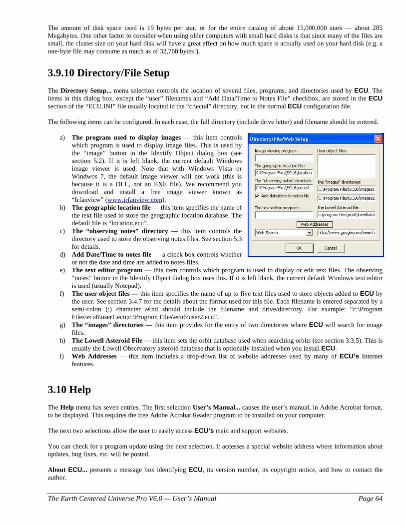
The Earth Centered Universe Pro V6.0 — User’s Manual Page 64
The amount of disk space used is 19 bytes per star, or for the entire catalog of about 15,000,000 stars — about 285 Megabytes. One other factor to consider when using older computers with small hard disks is that since many of the files are small, the cluster size on your hard disk will have a great effect on how much space is actually used on your hard disk (e.g. a one-byte file may consume as much as of 32,768 bytes!).
3.9.10 Directory/File Setup The Directory Setup... menu selection controls the location of several files, programs, and directories used by ECU. The items in this dialog box, except the “user” filenames and “Add Data/Time to Notes File” checkbox, are stored in the ECU section of the “ECU.INI” file usually located in the “c:\ecu4” directory, not in the normal ECU configuration file. The following items can be configured. In each case, the full directory (include drive letter) and filename should be entered.
a) The program used to display images — this item controls which program is used to display image files. This is used by the “image” button in the Identify Object dialog box (see section 5.2). If it is left blank, the current default Windows image viewer is used. Note that with Windows Vista or Windwos 7, the default image viewer will not work (this is because it is a DLL, not an EXE file). We recommend you download and install a free image viewer known as “Irfanview” (www.irfanview.com).
b) The geographic location file — this item specifies the name of the text file used to store the geographic location database. The default file is “location.ecu”.
c) The “observing notes” directory — this item controls the directory used to store the observing notes files. See section 5.3 for details.
d) Add Date/Time to notes file — a check box controls whether or not the date and time are added to notes files.
e) The text editor program — this item controls which program is used to display or edit text files. The observing “notes” button in the Identify Object dialog box uses this. If it is left blank, the current default Windows text editor is used (usually Notepad).
f) The user object files — this item specifies the name of up to five text files used to store objects added to ECU by the user. See section 3.4.7 for the details about the format used for this file. Each filename is entered separated by a semi-colon (;) character a€nd should include the filename and drive/directory. For example: “c:\Program Files\ecu6\user1.ecu;c:\Program Files\ecu6\user2.ecu”.
g) The “images” directories — this item provides for the entry of two directories where ECU will search for image files.
h) The Lowell Asteroid File — this item sets the orbit database used when searching orbits (see section 3.3.5). This is usually the Lowell Observatory asteroid database that is optionally installed when you install ECU.
i) Web Addresses — this item includes a drop-down list of website addresses used by many of ECU’s Internet features.
3.10 Help The Help menu has seven entries. The first selection User’s Manual... causes the user’s manual, in Adobe Acrobat format, to be displayed. This requires the free Adobe Acrobat Reader program to be installed on your computer. The next two selections allow the user to easily access ECU’s main and support websites. You can check for a program update using the next selection. It accesses a special website address where information about updates, bug fixes, etc. will be posted. About ECU... presents a message box identifying ECU, its version number, its copyright notice, and how to contact the author.
The Earth Centered Universe Pro V6.0 — User’s Manual Page 65
Willman-Bell Credits... presents a message box identifying that ECU contains source code that which is copyrighted by Jeffrey Sax. The source code referred to, provides high accuracy astronomical calculations based on the algorithms described in the book: Astronomical Algorithms by Jean Meuss (distributed by Willman-Bell). The message given in the message box is a requirement of distributing programs containing Jeffrey’s source code. And finally, Other Credits... presents a dialog box that recognizes the efforts of the many amateur and professional astronomers responsible for the preparation and maintenance of most of the databases used by ECU. It also acknowledges certain trademarks and copyrights.
4. Databases and Calculations This section describes the databases built-in to ECU and the astronomical calculations used. ECU contains many databases. The databases covered in this section include the stellar (see section 4.1), deep sky (see section 4.2), variable star (see section 4.3), and double star (see section 4.4) databases. Other databases (not described in this manual) include the user object, label, constellation lines and borders, and geographic location databases. For information about the format of orbit (comets and asteroids) databases see sections 3.5.1 and 3.5.8. ECU uses the algorithms described in the book: “Astronomical Algorithms” by Jean Meuss (published by Willman-Bell, Inc.) for all of the “high accuracy” solar system calculations and most other astronomical calculations as well. These “high-accuracy” positions of the planets and the Sun (see section 3.3.4.1) are derived from the planetary theory VSOP87 (see “Planetary theories in rectangular and spherical variables. VSOP solutions,” by P. Bretagnon and G. Francou, Astronomy and Astrophysics 202, 309-315 (1988)). The time-span validity of these positions is about 2000BC to 6000AD. Beyond this time-span, positions may be unreliable. The “high accuracy” positions of the Moon are derived from the lunar theory ELP2000 (see “The lunar ephemeris ELP 2000,” by M. Chapront-Touze and J Chapront, Astronomy and Astrophysics, 124, 50-62 (1983)). The “low accuracy” solar system calculations are mostly from the book: “Practical Astronomy with your Calculator” by Peter Duffett-Smith. These should not be used, except when using very old slow computers and are not accurate more than a few decades from the present time.
4.1 Stellar Databases ECU includes four stellar databases: the Yale Bright Star Catalog (YBSC), the Smithsonian Astrophysical Observatory (SAO) Star Catalog, the Tycho-2 Star Catalog, and the Hubble Guide Star Catalog. The YBSC/SAO combination compliments the Tycho-2 Star Catalog. Each of these databases is described in detail in sections 4.1.1 to 4.1.4. It also supports, but does not include, the US Naval Observatory’s A-2.0 and SA-2.0 Star Catalogs — see section 4.1.5 for details.
4.2.1 Yale Bright Star Catalog The Yale Bright Star Catalog (version 5 – 1982) contains 9110 stars to magnitude 6.5. It is contained in the files: YBSC1.ECU, YBSC2.ECU, and YBSC3.ECU. This catalog is designed to work in concert with the SAO Star Catalog (see next section). The following information is included for each star:
a) Position (J2000.0 epoch) b) Visual Magnitude (nearest tenth) c) Proper Name (if available) d) Bayer and Flamsteed Designation (if available) e) HR Number
The Earth Centered Universe Pro V6.0 — User’s Manual Page 66
f) Henry Draper Number g) SAO Number h) B-V Color i) Spectral Type j) Proper Motion
4.2.2 Smithsonian Astrophysical Observatory Star Catalog The Smithsonian Astrophysical Observatory (SAO) Star Catalog contains some 259,000 stars. The Yale stars and those with the magnitude unknown were extracted leaving a database of 245,654 stars to about magnitude 9.5. It is included in the files: SAO1.ECU and SAO2.ECU. This catalog is designed to work in concert with the Yale Bright Star Catalog since there are no duplicate stars. The following information is included for each star:
a) Position (J2000.0 epoch – 10 arc-second resolution in declination, 20 arc-second resolution in right ascension) b) Magnitude (nearest tenth) c) SAO Number d) Spectral Type
4.2.3 Tycho-2 Star Catalog The Tycho-2 Star Catalog is a production of the European Space Agency and is based on data acquired by the Hipparcos astrometric satellite. For detailed information about the catalog see www.astro.ku.dk/~erik/Tycho-2. The base catalog contains about 2.5 million stars and contains stars as faint as magnitude 12-13. Since the base Tycho-2 Star Catalog is missing some stars, including many bright ones, the database used by ECU was supplemented with data from the Hipparcos Catalog and two supplement catalogs. A total of 2,436,615 stars are in the database that is contained in the files TYC1.ECU to TYC5.ECU. For efficiency reasons, the database was split into bright (magnitude 6.2 and brighter) and faint (fainter than magnitude 6.2) stars. The following information is included for each star:
a) Position (J2000.0 epoch) b) Magnitude (nearest tenth) c) Tycho Catalog Number d) Hipparcos Catalog Number (if available) e) Henry Draper Catalog Number (if available) f) Corrected V Magnitude (nearest hundredth, if available) g) Corrected B Magnitude (nearest hundredth, if available) h) Parallax (if available, distance is computed from the parallax by ECU) i) Parallax Error Estimate (if available) j) Proper Motion (if available)
4.2.4 Hubble Guide Star Catalog The Hubble Guide Star Catalogue (called the GSC or HGSC) can be installed via a separate installer (see section 1.2 to install it). It is derived from a pair of CD-ROM disks published by The Space Telescope Science Institute and used by Nova Astronomics under license. These disks contain about 15,000,000 stars, with the faintest being about magnitude 15.5. ECU ignores the objects classified as non-stellar objects. The GSC was originally created to provide a selection of guide-stars in support of the Hubble Space Telescope. In dense regions of the Milky Way, the faintest stars are only about magnitude 13. This is because the goal in selecting stars was to have a nominal number of stars per square degree, thus in dense regions there were more bright stars to choose from. A large amount of information regarding the GSC is included in Appendix A of this manual (a requirement according to its license agreement).
The Earth Centered Universe Pro V6.0 — User’s Manual Page 67
The GSC provides the following information for each star:
a) Position (J2000.0 epoch) b) Magnitude (nearest tenth) c) Position Error Estimate d) Magnitude Error Estimate e) Magnitude Band f) Plate ID
With today’s large hard disks, it is recommended that you install the entire GSC to your hard disk. It used the GSC, be sure to enable the “Hubble Guide Star Catalog” check box in the Stars… item in the Field menu (see section 3.4.4).
4.2.5 US Naval Observatory Star Catalogs In addition to the star catalogs included with ECU, two additional catalogs (not available from Nova Astronomics due to licensing issues) produced by the US Naval Observatory are supported. These two catalogs are (quoted from their website): USNO-A2.0 — contains entries for over a half billion stars (526,230,881, to be exact!) which were detected in the digitized images of three photographic sky surveys. For the entire northern sky and the southern sky down to declinations of -30°, all the photographic plates were part of the original Palomar Optical Sky Survey (POSS-I). Photographs were taken on blue- and red-sensitive emulsions. Only those stars that were detected in both colors were included in the USNO-A2.0 catalog. The rest of the southern sky was covered by the Science Research Council (SRC)-J survey and the European Southern Observatory (ESO)-R survey. Again, only stars appearing in both colors were accepted for the final catalogue. USNO-SA2.0 — is a subset of USNO-A2.0 that is a lot easier to handle on a small computer because it contains only a tenth as many stars as the parent catalog (54,787,624 stars in all). The goal in creating this smaller catalog was to provide a spatially uniform distribution of stars in an intermediate range of magnitudes that would be useful as a ``reference grid'' for astrometric analysis. For details about these two catalogs see: http://ftp.nofs.navy.mil/projects/pmm/catalogs.html. Both of these catalogs are incredible resources for deep sky observers and CCD imagers. The A-2.0 includes stars over the entire sky down to fainter than 19th magnitude – truly incredible! The SA-2.0 is less useful since, when plotted, it looks like the stars in the sky are laid down on a grid – not useful for creating a star chart, but very useful for those doing astrometry (measuring accurate positions of objects). These catalogs can be downloaded from the Internet using a high-speed connection and a great deal of patience. You may have better luck obtaining a copy on DVD from another ECU user – I suggest you inquire about this on the ECUsers forum (see groups.yahoo.com/group/ecusers). Download information for the USNO A2.0: ftp.nofs.navy.mil/projects/pmm/a.response Download information for the USNO SA2.0: ftp.nofs.navy.mil/projects/pmm/sa.response The A2.0 is about 6.3 Gigabytes for the entire sky. The sky north of –45 degrees declination fits nicely on one recordable DVD. Both catalogs are organized into declination zones 7.5 degrees high, each zone being comprised of an index file and a data file. The zones files are named ‘zoneXXXX.acc’ (index) and ‘zoneXXXX.cat’ (data) where XXXX is the number of degrees north of -90 degrees in declination — ranging from ‘0000’ to ‘1725’. The ‘0000’ file means data for stars from –90 to –82.5 degrees and the ‘1725’ file means data for stars from +82.5 to +90 degrees. ECU can handle any fraction of the whole database, as long as both the index and data file for each zone is present. To configure ECU to use the USNO star catalogs, see section 3.4.4.
4.2 Deep Sky Databases
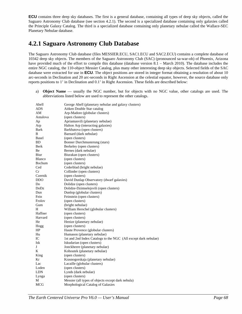
The Earth Centered Universe Pro V6.0 — User’s Manual Page 68
ECU contains three deep sky databases. The first is a general database, containing all types of deep sky objects, called the Saguaro Astronomy Club database (see section 4.2.1). The second is a specialized database containing only galaxies called the Principle Galaxy Catalog. The third is a specialized database containing only planetary nebulae called the Wallace-SEC Planetary Nebulae database.
4.2.1 Saguaro Astronomy Club Database The Saguaro Astronomy Club database (files MESSIER.ECU, SAC1.ECU and SAC2.ECU) contains a complete database of 10342 deep sky objects. The members of the Saguaro Astronomy Club (SAC) (pronounced sa-war-oh) of Phoenix, Arizona have provided much of the effort to compile this database (database version 8.1 – March 2010). The database includes the entire NGC catalog, the 110-object Messier Catalog, plus many other interesting deep sky objects. Selected fields of the SAC database were extracted for use in ECU. The object positions are stored in integer format obtaining a resolution of about 10 arc-seconds in Declination and 20 arc-seconds in Right Ascension at the celestial equator, however, the source database only reports positions to 1’ in Declination and 0.1’ in Right Ascension. These fields are described below:
a) Object Name — usually the NGC number, but for objects with no NGC value, other catalogs are used. The abbreviations listed below are used to represent the other catalogs.
Abell George Abell (planetary nebulae and galaxy clusters) ADS Aitken Double Star catalog AM Arp-Madore (globular clusters) Antalova (open clusters) Ap Apriamasvili (planetary nebulae) Arp Halton Arp (interacting galaxies) Bark Barkhatova (open clusters) B Barnard (dark nebulae) Basel (open clusters) BD Bonner Durchmusterung (stars) Berk Berkeley (open clusters) Be Bernes (dark nebulae) Biur Biurakan (open clusters) Blanco (open clusters) Bochum (open clusters) Ced Cederblad (bright nebulae) Cr Collinder (open clusters) Czernik (open clusters) DDO David Dunlap Observatory (dwarf galaxies) Do Dolidze (open clusters) DoDz Dolidze-Dzimselejsvili (open clusters) Dun Dunlop (globular clusters) Fein Feinstein (open clusters) Frolov (open clusters) Gum (bright nebulae) H William Herschel (globular clusters) Haffner (open clusters) Harvard (open clusters) He Henize (planetary nebulae) Hogg (open clusters) HP Haute Provence (globular clusters) Hu Humason (planetary nebulae) IC 1st and 2nd Index Catalogs to the NGC (All except dark nebulae) Isk Iskudarian (open clusters) J Jonckheere (planetary nebulae) K Kohoutek (planetary nebulae) King (open clusters) Kr Krasnogorskaja (planetary nebulae) Lac Lacaille (globular clusters) Loden (open clusters) LDN Lynds (dark nebulae) Lynga (open clusters) M Messier (all types of objects except dark nebula) MCG Morphological Catalog of Galaxies
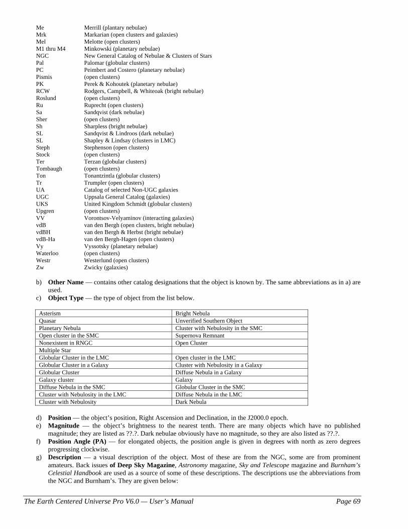
The Earth Centered Universe Pro V6.0 — User’s Manual Page 69
Me Merrill (plantary nebulae) Mrk Markarian (open clusters and galaxies) Mel Melotte (open clusters) M1 thru M4 Minkowski (planetary nebulae) NGC New General Catalog of Nebulae & Clusters of Stars Pal Palomar (globular clusters) PC Peimbert and Costero (planetary nebulae) Pismis (open clusters) PK Perek & Kohoutek (planetary nebulae) RCW Rodgers, Campbell, & Whiteoak (bright nebulae) Roslund (open clusters) Ru Ruprecht (open clusters) Sa Sandqvist (dark nebulae) Sher (open clusters) Sh Sharpless (bright nebulae) SL Sandqvist & Lindroos (dark nebulae) SL Shapley & Lindsay (clusters in LMC) Steph Stephenson (open clusters) Stock (open clusters) Ter Terzan (globular clusters) Tombaugh (open clusters) Ton Tonantzintla (globular clusters) Tr Trumpler (open clusters) UA Catalog of selected Non-UGC galaxies UGC Uppsala General Catalog (galaxies) UKS United Kingdom Schmidt (globular clusters) Upgren (open clusters) VV Vorontsov-Velyaminov (interacting galaxies) vdB van den Bergh (open clusters, bright nebulae) vdBH van den Bergh & Herbst (bright nebulae) vdB-Ha van den Bergh-Hagen (open clusters) Vy Vyssotsky (planetary nebulae) Waterloo (open clusters) Westr Westerlund (open clusters) Zw Zwicky (galaxies)
b) Other Name — contains other catalog designations that the object is known by. The same abbreviations as in a) are
used. c) Object Type — the type of object from the list below.
Asterism Bright Nebula Quasar Unverified Southern Object Planetary Nebula Cluster with Nebulosity in the SMC Open cluster in the SMC Supernova Remnant Nonexistent in RNGC Open Cluster Multiple Star Globular Cluster in the LMC Open cluster in the LMC Globular Cluster in a Galaxy Cluster with Nebulosity in a Galaxy Globular Cluster Diffuse Nebula in a Galaxy Galaxy cluster Galaxy Diffuse Nebula in the SMC Globular Cluster in the SMC Cluster with Nebulosity in the LMC Diffuse Nebula in the LMC Cluster with Nebulosity Dark Nebula
d) Position — the object’s position, Right Ascension and Declination, in the J2000.0 epoch. e) Magnitude — the object’s brightness to the nearest tenth. There are many objects which have no published
magnitude; they are listed as ??.?. Dark nebulae obviously have no magnitude, so they are also listed as ??.?. f) Position Angle (PA) — for elongated objects, the position angle is given in degrees with north as zero degrees
progressing clockwise. g) Description — a visual description of the object. Most of these are from the NGC, some are from prominent
amateurs. Back issues of Deep Sky Magazine, Astronomy magazine, Sky and Telescope magazine and Burnham’s Celestial Handbook are used as a source of some of these descriptions. The descriptions use the abbreviations from the NGC and Burnham’s. They are given below:
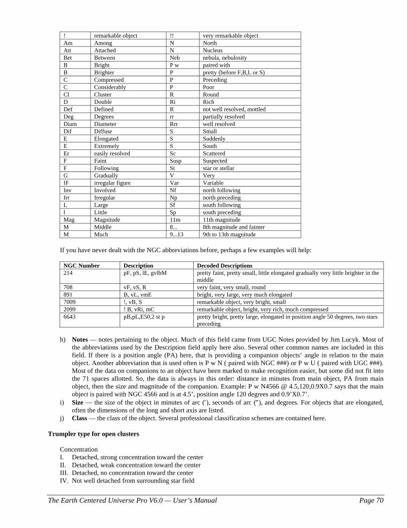
The Earth Centered Universe Pro V6.0 — User’s Manual Page 70
! remarkable object !! very remarkable object Am Among N North Att Attached N Nucleus Bet Between Neb nebula, nebulosity B Bright P w paired with B Brighter P pretty (before F,B,L or S) C Compressed P Preceding C Considerably P Poor Cl Cluster R Round D Double Ri Rich Def Defined R not well resolved, mottled Deg Degrees rr partially resolved Diam Diameter Rrr well resolved Dif Diffuse S Small E Elongated S Suddenly E Extremely S South Er easily resolved Sc Scattered F Faint Susp Suspected F Following St star or stellar G Gradually V Very IF irregular figure Var Variable Inv Involved Nf north following Irr Irregular Np north preceding L Large Sf south following l Little Sp south preceding Mag Magnitude 11m 11th magnitude M Middle 8... 8th magnitude and fainter M Much 9...13 9th to 13th magnitude
If you have never dealt with the NGC abbreviations before, perhaps a few examples will help:
NGC Number Description Decoded Descriptions 214 pF, pS, lE, gvlbM pretty faint, pretty small, little elongated gradually very little brighter in the
middle 708 vF, vS, R very faint, very small, round 891 B, vL, vmE bright, very large, very much elongated 7009 !, vB, S remarkable object, very bright, small 2099 ! B, vRi, mC remarkable object, bright, very rich, much compressed 6643 pB,pL,E50,2 st p pretty bright, pretty large, elongated in position angle 50 degrees, two stars
preceding
h) Notes — notes pertaining to the object. Much of this field came from UGC Notes provided by Jim Lucyk. Most of the abbreviations used by the Description field apply here also. Several other common names are included in this field. If there is a position angle (PA) here, that is providing a companion objects’ angle in relation to the main object. Another abbreviation that is used often is P w N ( paired with NGC ###) or P w U ( paired with UGC ###). Most of the data on companions to an object have been marked to make recognition easier, but some did not fit into the 71 spaces allotted. So, the data is always in this order: distance in minutes from main object, PA from main object, then the size and magnitude of the companion. Example: P w N4566 @ 4.5,120,0.9X0.7 says that the main object is paired with NGC 4566 and is at 4.5’, position angle 120 degrees and 0.9’X0.7’.
i) Size — the size of the object in minutes of arc (′), seconds of arc (″), and degrees. For objects that are elongated, often the dimensions of the long and short axis are listed.
j) Class — the class of the object. Several professional classification schemes are contained here. Trumpler type for open clusters
Concentration I. Detached, strong concentration toward the center II. Detached, weak concentration toward the center III. Detached, no concentration toward the center IV. Not well detached from surrounding star field
The Earth Centered Universe Pro V6.0 — User’s Manual Page 71
Range in brightness 1. Small 2. Moderate range 3. Large range Richness p Poor (<50 stars) m Moderately rich (50-100 stars) r Rich (>100 stars)
An “n” following the Trumpler type denotes nebulosity in cluster
Shapley-Sawyer concentration rating for globular clusters
The values range from 1 to 12, smaller numbers are more concentrated clusters.
Vorontsov-Velyaminov type for planetary nebulae
1. Stellar 2. Smooth disk (a, brighter center; b, uniform brightness; c, traces of ring structure) 3. Irregular disk (a, very irregular brightness; b, traces of ring structure) 4. Ring structure 5. Irregular form similar to diffuse nebula 6. Anomalous form, no regular structure
Some very complex forms may combine two types.
Hubble type for galaxies
E elliptical, E0 is roundest to E7 is flattest subgroups; ‘d’ is dwarf, ‘c’ is supergiant, ‘D’ has diffuse halo S Spiral, ‘a’ has tightly wound arms, ‘b’ has moderately wound arms and ‘c’ has loosely wound arms SB Spiral with central bar Ir Irregular
4.2.2 Principle Galaxy Catalog ECU includes the 2002 Edition of the Catalog of Principal Galaxies (PGC), which is a catalog containing 980,947 galaxies. It was compiled by a group of professional astronomers led by G. Paturel of France. Selected fields from the original PGC database were extracted for use in ECU. These fields are described below:
a) Galaxy Names — the PGC number is the primary name of each galaxy. Up to four other identifications are included. These are from the NGC, UGC, MCG, Messier, and IRAS catalogs and others.
b) Position — the object’s position, Right Ascension and Declination, in the J2000.0 epoch. c) Magnitude — the object’s brightness to the nearest tenth. There are many galaxies with no published magnitude;
they are listed as ??.?. d) Size — the size of the object in minutes and tenths of minutes of arc (′). For galaxies that are elongated, often the
dimensions of the long and short axis are listed. e) Class — the class, or morphological type, of the galaxy coded according to the Hubble Classification Scheme (see
below) with additions for unusual galaxies. For more information see: http://en.wikipedia.org/wiki/Hubble_sequence
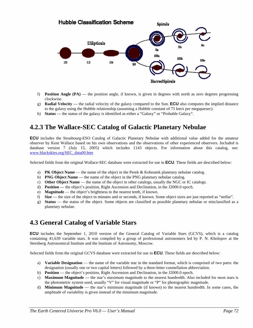
The Earth Centered Universe Pro V6.0 — User’s Manual Page 72
f) Position Angle (PA) — the position angle, if known, is given in degrees with north as zero degrees progressing
clockwise. g) Radial Velocity — the radial velocity of the galaxy compared to the Sun. ECU also computes the implied distance
to the galaxy using the Hubble relationship (assuming a Hubble constant of 75 km/s per megaparsec). h) Status — the status of the galaxy is identified as either a “Galaxy” or “Probable Galaxy”.
4.2.3 The Wallace-SEC Catalog of Galactic Planetary Nebulae ECU includes the Strasbourg-ESO Catalog of Galactic Planetary Nebulae with additional value added for the amateur observer by Kent Wallace based on his own observations and the observations of other experienced observers. Included is database version 7 (July 15, 2005) which includes 1143 objects. For information about this catalog, see: www.blackskies.org/SEC_data00.htm Selected fields from the original Wallace-SEC database were extracted for use in ECU. These fields are described below:
a) PK Object Name — the name of the object in the Perek & Kohoutek planetary nebulae catalog. b) PNG Object Name — the name of the object in the PNG planetary nebulae catalog. c) Other Object Name — the name of the object in other catalogs, usually the NGC or IC catalogs. d) Position — the object’s position, Right Ascension and Declination, in the J2000.0 epoch. e) Magnitude — the object’s brightness to the nearest tenth, if known. f) Size — the size of the object in minutes and or seconds, if known. Some object sizes are just reported as “stellar”. g) Status — the status of the object. Some objects are classified as possible planetary nebulae or misclassified as a
planetary nebulae.
4.3 General Catalog of Variable Stars ECU includes the September 1, 2010 version of the General Catalog of Variable Stars (GCVS), which is a catalog containing 41,639 variable stars. It was compiled by a group of professional astronomers led by P. N. Kholopov at the Sternberg Astronomical Institute and the Institute of Astronomy, Moscow. Selected fields from the original GCVS database were extracted for use in ECU. These fields are described below:
a) Variable Designation — the name of the variable star in the standard format, which is comprised of two parts: the designation (usually one or two capital letters) followed by a three-letter constellation abbreviation.
b) Position — the object’s position, Right Ascension and Declination, in the J2000.0 epoch. c) Maximum Magnitude — the star’s maximum magnitude to the nearest hundredth. Also included for most stars is
the photometric system used, usually “V” for visual magnitude or “P” for photographic magnitude. d) Minimum Magnitude — the star’s minimum magnitude (if known) to the nearest hundredth. In some cases, the
amplitude of variability is given instead of the minimum magnitude.
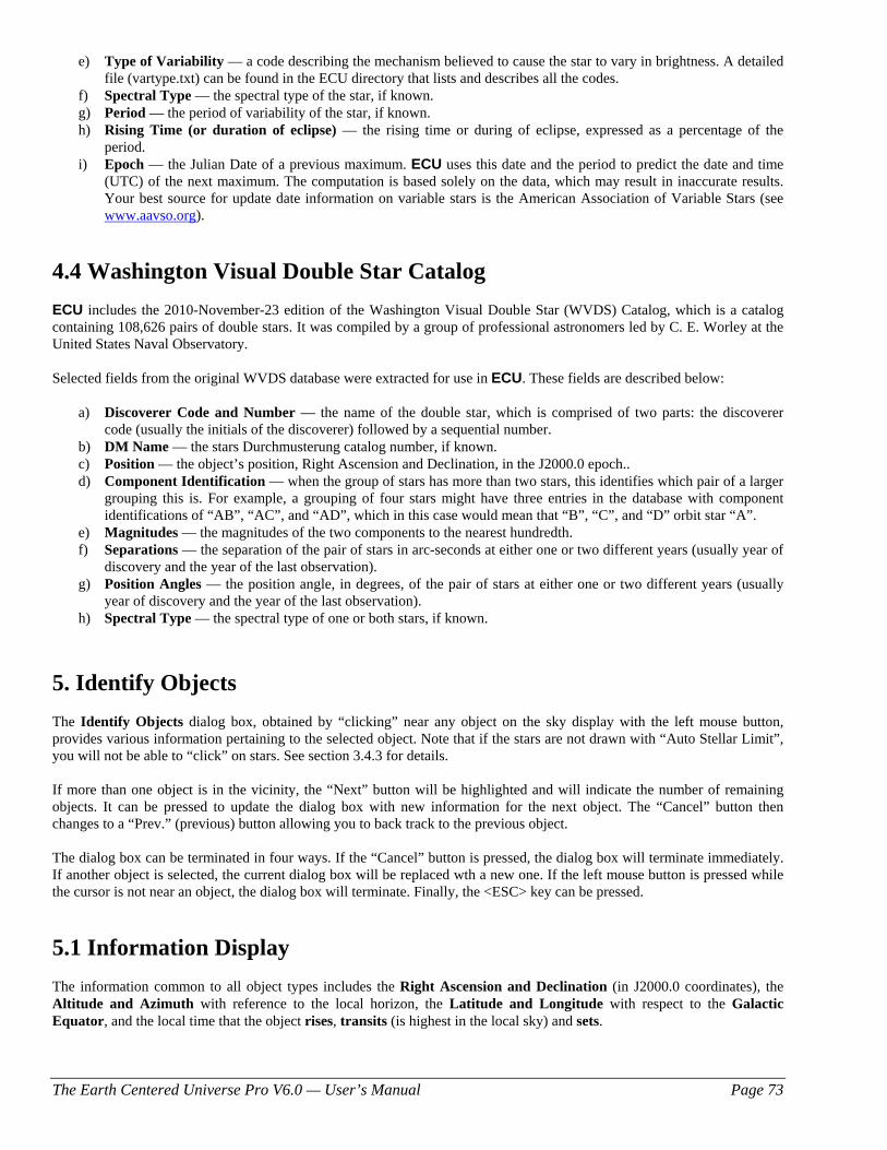
The Earth Centered Universe Pro V6.0 — User’s Manual Page 73
e) Type of Variability — a code describing the mechanism believed to cause the star to vary in brightness. A detailed file (vartype.txt) can be found in the ECU directory that lists and describes all the codes.
f) Spectral Type — the spectral type of the star, if known. g) Period — the period of variability of the star, if known. h) Rising Time (or duration of eclipse) — the rising time or during of eclipse, expressed as a percentage of the
period. i) Epoch — the Julian Date of a previous maximum. ECU uses this date and the period to predict the date and time
(UTC) of the next maximum. The computation is based solely on the data, which may result in inaccurate results. Your best source for update date information on variable stars is the American Association of Variable Stars (see www.aavso.org).
4.4 Washington Visual Double Star Catalog ECU includes the 2010-November-23 edition of the Washington Visual Double Star (WVDS) Catalog, which is a catalog containing 108,626 pairs of double stars. It was compiled by a group of professional astronomers led by C. E. Worley at the United States Naval Observatory. Selected fields from the original WVDS database were extracted for use in ECU. These fields are described below:
a) Discoverer Code and Number — the name of the double star, which is comprised of two parts: the discoverer code (usually the initials of the discoverer) followed by a sequential number.
b) DM Name — the stars Durchmusterung catalog number, if known. c) Position — the object’s position, Right Ascension and Declination, in the J2000.0 epoch.. d) Component Identification — when the group of stars has more than two stars, this identifies which pair of a larger
grouping this is. For example, a grouping of four stars might have three entries in the database with component identifications of “AB”, “AC”, and “AD”, which in this case would mean that “B”, “C”, and “D” orbit star “A”.
e) Magnitudes — the magnitudes of the two components to the nearest hundredth. f) Separations — the separation of the pair of stars in arc-seconds at either one or two different years (usually year of
discovery and the year of the last observation). g) Position Angles — the position angle, in degrees, of the pair of stars at either one or two different years (usually
year of discovery and the year of the last observation). h) Spectral Type — the spectral type of one or both stars, if known.
5. Identify Objects The Identify Objects dialog box, obtained by “clicking” near any object on the sky display with the left mouse button, provides various information pertaining to the selected object. Note that if the stars are not drawn with “Auto Stellar Limit”, you will not be able to “click” on stars. See section 3.4.3 for details. If more than one object is in the vicinity, the “Next” button will be highlighted and will indicate the number of remaining objects. It can be pressed to update the dialog box with new information for the next object. The “Cancel” button then changes to a “Prev.” (previous) button allowing you to back track to the previous object.
The dialog box can be terminated in four ways. If the “Cancel” button is pressed, the dialog box will terminate immediately. If another object is selected, the current dialog box will be replaced wth a new one. If the left mouse button is pressed while the cursor is not near an object, the dialog box will terminate. Finally, the <ESC> key can be pressed.
5.1 Information Display The information common to all object types includes the Right Ascension and Declination (in J2000.0 coordinates), the Altitude and Azimuth with reference to the local horizon, the Latitude and Longitude with respect to the Galactic Equator, and the local time that the object rises, transits (is highest in the local sky) and sets.
The Earth Centered Universe Pro V6.0 — User’s Manual Page 74
Two other parameters are given: Air Mass and Extinction. Airmass is an estimate of how much atmosphere you are looking through compared to straight up — as airmass increases objects become dimmer, more red in color, and seeing (atmospheric turbulence) becomes worse. The airmass increases as objects become closer to the horizon. Extinction is an estimate (in magnitudes) for how much an object is "dimmed" due to the current air mass. If more information is present than can be displayed in the available space, a scroll bar is utilized allowing the user to scroll down to access more information. Each object type is listed below with each one’s specific information that is displayed in the identify objects dialog box.
a) Sun — the sun’s distance, in astronomical units and in kilometers; its light travel time, in minutes; its size, in minutes of arc, and the solar longitude.
b) Moon — the moon’s distance from the Earth, in kilometers; its size, in minutes of arc; its phase; its phase angle (and age, in days); and its illuminated fraction (in percent).
c) Planets — the planet’s magnitude; its distance from the Earth, in astronomical units and in kilometers; its light travel time, in hours and minutes; its size, in seconds of arc; its phase (0 to 1); and its rate of motion in several formats.
d) Comets or Asteroids — its magnitude; its distance from the Earth and the Sun in astronomical units and in kilometers; its light travel time, in hours and minutes; its solar elongation; for asteroids, its phase angle; and its rate of motion in several formats.
e) Yale Bright Star Catalogue Stars — the star’s magnitude; its Bayer/Flamsteed identification; its Yale Catalogue number; its SAO Catalogue number; its Henry Draper Catalogue number; its spectral classification; its color as B-V; and its proper motion.
f) SAO Catalogue Stars — the star’s magnitude; its SAO Catalogue number; and its spectral classification. g) Tycho-2 Catalogue Stars — the star’s magnitude (in both B and V colors); its Tycho-2 Catalogue number, its
Hipparcos number (if applicable), its HD number (if applicable), its measured parallax (with uncertainty), the implied distance (in light years with uncertainty), and its proper motion.
h) Hubble Guide Stars — the star’s magnitude; its GSC Catalogue number; its estimated position error; its estimated magnitude error; its magnitude band; and its Plate ID.
i) US Naval Observatory Stars — the star’s magnitude (both blue and red, if known); its identity (by zone file and star number), and the plate number (POSS or SRC) that it originated from.
j) SAC Deep Sky Objects — the object’s magnitude; its primary and other names; its description; its size; its position angle; the object class and various notes are displayed. See section 4.2.1 for a detailed description.
k) PGC Galaxies — the galaxy’s magnitude; its primary and up to four other names; its morphological type, its size; its position angle; its class and its radial velocity. The radial velocity is also converted into its distance using the Hubble relationship (with a Hubble constant of 75 km/s per megaparsec). See section 4.2.2 for a detailed description.
l) Variable Stars — the star’s maximum and minimum magnitude; the designation of the variable star; its type of variability; its period; its spectral type; its rising time (or duration of eclipse); and the Julian date of a previous maximum. The date and time of a future maximum is computed using the period and the epoch of the previous maximum. See section 4.3 for a detailed description.
m) Double Stars — the combined magnitude of the pair; the discoverer code of the pair; its Durchmusterung catalog number; the magnitudes of both stars; the separation and position angle at up to two dates; and its spectral type. See section 4.4 for a detailed description.
n) Planetary Nebulae — the PK and PNG object name; any other name (usually NGC or IC); the object’s magnitude; its size; and its status. See section 4.3.3 for a detailed description.
o) User Objects — the object’s magnitude (if known); its user number; and its text description.
5.2 Viewing Images Viewing images of objects is provided by ECU running an image viewer program with the name of the image file to view. This is accomplished by pressing the “Image” button. If an image for the identified object or the image viewer program is not present, the “Image” button will be disabled.
The Earth Centered Universe Pro V6.0 — User’s Manual Page 75
To setup an image viewer program to use with ECU, see section 3.9.10, the Directory/File Setup… dialog box. The location of the image files (two locations on your computer are searched) is also controlled by the user in the same Directory/File Setup… dialog box. ECU looks for image files in a number of ways. In the simplest form, the name of the image files must be the same as the primary or other object name that appears in the “Identify Objects” dialog box for the object. For example, an image of the Moon would be called “MOON.GIF” if the image were in “GIF” format. Or an image of NGC7009 (the Saturn Nebula) would be called “NGC7009.JPG” if the image were in “JPG” format. The filename used is usually exactly the same as the object’s primary name, however, because of the restrictions on the naming of files imposed by Windows, some names of objects may not work directly (for example, if the name contains letters such as “:”, “.” or “\” that are not allowed in filenames). In these cases, ECU creates a “compatible” filename automatically. The easiest way to determine is the “compatible” filename is to use the “Notes” feature (see section 5.3) since it uses the same algorithm. There is also a more advanced way that ECU searches for image files. This method searches for a file ending in “.txt” (a text file) that the user creates with a text editor such as the Windows Notepad. This text file should contain the image file names one per line and in total, up to 50 images of each object can be specified. Filenames specified can be either:
1. unqualified — containing no directory information, in which case the specified image file must be in the same directory
2. fully-qualified — containing the complete location of the image file (including drive and directory). An example image “text” file named “M42.TXT” and stored in the “c:\ecu4\images1” directory for the Orion Nebula (M42) is: m42.jpg - an image file in “c:\Program Files\ecu6\images1” directory orion.jpg - another image file in same directory c:\ecu4\images\m42.jpg - an image file in another directory c:\images\m42a.jpg - an image file in yet another directory c:\images\m42b.jpg - an image file in same directory with different name d:\images\m42.jpg - an image file from the CD-ROM image directory
5.3 Notes You can add your own “notes” about any object in ECU’s database by clicking on the notes button in the Identify Object dialog box. ECU then creates a file named after the object, stores it in the “notes” directory (see section 3.9.10), and starts a text editor program (also see section 3.9.10). Below is a sample file, which would be created for Messier Object 42 (the Orion Nebula). It includes both known names of the object. Depending on the “Add Date/Time to notes file” setting in the Directory/File… dialog box (see section 3.9.10), a time/date stamp (the current date and time in local and UTC formats) is optionally added to the file. Object Name: M42 Other Name: NGC 1976 LMT: 2004/12/25 09:18pm (UTC: 2004/12/26 01:18) Today's Notes: After adding your notes, remember to save the file and close the text editor program. If the file was already present, it is not overwritten, but rather a new time/date stamp is appended to the bottom of the existing file allowing the user to add more notes. The filename created is usually exactly the same as the object’s primary name with “.TXT” added to the end. In the example above, the file would have been called “M101.TXT”. Because of the restrictions on the naming of files imposed by
The Earth Centered Universe Pro V6.0 — User’s Manual Page 76
Windows, some names of objects may work directly (for example, if the name contains letters such as “:”, “.” or “\” that are not allowed in filenames). In these cases, ECU creates a “compatible” filename automatically.
5.4 Internet Features Several different types of web searches can also be invoked directly from the Identify Object dialog box. Note that each object type only makes available the appropriate search types. Select the desired type of web search using the drop-down list and then press the “GO” button. The object’s primary name or the object’s position (as appropriate) is used for the search string. A web-browser window will appear with the result of the search. You must be connected to the Internet to use this feature. The available types of web searches are:
a) Web Search — performs a usual web search using the site www.google.com. b) Image Search —performs an image search using the site images.google.com. This search is surprisingly effective
at finding images of many astronomical objects. c) Retrieve DSS Image — retrieves an image of the sky, from the Digitized Sky Survey, located at the object’s
location. The size of the image is set using the DSS Image Size… menu item (see section 3.9.4). d) SIMBAD Database Search — performs a search of the on-line SIMBAD Astronomical database hosted at
simbad.u-strasbg.fr/Simbad. This database provides basic data, cross-identifications and bibliography for astronomical objects outside the solar system.
e) NED Search — performs a search of the on-line NASA/IPAC Extragalactic Database hosted at nedwww.ipac.caltech.edu. This database contains positions, basic data, and over 12,400,000 names for 8,100,000 extragalactic objects, as well as more than 2,700,000 bibliographic references to over 61,000 published papers, and 63,000 notes from catalogs and other publications.
f) AAVSO Search — performs a search of the on-line AAVSO database which can be used to access charts, light curves, and observation data for variable stars in the AAVSO database.
g) GCVS Search — performs a search of the on-line General Catalog of Variable Stars database hosted at the Sternberg Astronomical Institute in Moscow, Russia.
The web site address used complete each search type is set in the Directory/File/Web Setup… dialog (see section 3.9.10).
5.5 Other Buttons The “Copy” button copies the text contents of the dialog box to the clipboard so that it can be pasted into other applications. The “Precess” button precesses the object’s coordinates to the epoch of the current date. Pressing the “Center Object” button will cause the sky display to be re-drawn centered at the identified object. Pressing the “Place Target” button will cause a default Field Target to be placed at the location of the selected object (see section 3.4.18.1). If the telescope interface is enabled, you will see the buttons “Sync Scope” and “Center Scope” buttons are used by the telescope functions. See section 6 for details.
6. Using ECU’s Telescope Interface Functions ECU provides extensive support for the control many different types of telescopes and focusers equipped with computer interfaces. In addition to those directly supported by ECU, many more are supported through drivers provided by the ASCOM Initiative. For the list of supported interfaces, see Section 3.8.15. Included in the list of supported interfaces are Nova Astronomics’ own encoder interfaces: The Micro-Guiders. The Micro-Guider I and III are no longer available. The current model is the Micro-Guider 5. For full details about this device, see the Nova Astronomics website.
The Earth Centered Universe Pro V6.0 — User’s Manual Page 77
Even though many of the menu selections and mouse/keyboard functions used by the telescope interface functions are shared among the many telescope interfaces, they do operate differently and thus each general type of telescope interface is separately described in the sections below. See section 3.8.15 to determine which section pertains to your telescope interface type. Reference material for all of the telescope menu selections is found in section 3.8.
6.1 Using a “GOTO” Type Telescope With ECU To use a “GOTO” type telescope with ECU, you will need an RS232 cable to connect your telescope to your computer. This cable is available from your telescope retailer or telescope manufacturer or you can often make one yourself according to the instructions in your telescope instruction manual. Be careful in doing so, however, since the vast majority of problems that users report are directly attributable to incorrectly made cables. Before attempting to use ECU with your telescope, you should have read your telescope instruction manual thoroughly and be able to confidently use it “stand-alone” without the aid of a computer.
6.1.1 Initial Set Up The first time you use the “GOTO” telescope interface, you will have to make some adjustments to ECU’s settings. Enter the Telescope Type and General Settings... menu selection from the Telescope menu (see section 3.8.15 for details). Select the “Telescope Interface Type” to match your telescope type. Select the communications port that is used to connect the telescope to the computer. When selecting a telescope interface type, the “update delay” and “baud rate” are automatically set to suitable values. Under normal circumstances, you should not have to change these parameters, however, if your PC or telescope operates slowly when the telescope interface is enabled, try using a higher “update delay”. Save these settings permanently by using the File ⇒ Save or File ⇒ Save As... menu selections.
6.1.2 Enabling the Telescope Interface Prior to enabling the telescope interface, a number of steps must be completed as listed below:
1. Connect the RS232 cable between the telescope and your computer. 2. Turn the telescope on. 3. Align the telescope following the procedure outlined in its instruction manual. 4. Some telescopes, such as the Celestron NexStars, require their RS232 interfaces to be enabled before they will
respond to commands from ECU. 5. Enable the telescope interface by selecting the Enable Telescope Interface menu selection (see section 3.7.1) or
press its button on the tool bar. 6. If no error messages were displayed, the telescope interface should be functional. 7. If desired, you can use the Set Telescope Time... (see section 3.8.11) and Set Telescope Geographic Location...
(see section 3.8.12) menu selections for Meade LX200 and other similar telescopes. Note that with the Astro-Physics GTO mount, the initialization procedure sets both the time and location, so it’s important that ECU’s location and your computer’s time are both set correctly.
To disable the telescope interface, just select the Enable Telescope Interface menu selection again or press its tool bar button.
6.1.3 Using the Telescope Interface Once enabled (see section 6.1.2), the telescope interface is quite easy to use. Several functions are provided; each is described below.
The Earth Centered Universe Pro V6.0 — User’s Manual Page 78
1. Position Display — if the menu selection Show Position (see section 3.8.4) is enabled, an indicator will be drawn on the sky display at the position which the telescope is pointed to and will follow it in real-time. If the menu selection Track Telescope (see section 3.8.7) is enabled, and the telescope position moves out of the sky display, it will be re-drawn with the current telescope position at the center of the sky display. You should also read about the Auto Track Telescope feature in section 3.8.8. The type of indicator displayed depends on the state of the menu selection Use Default Field Targets (see section 3.8.5). If checked, the position display will be the programmable field circles (or rectangle) as described in section 3.4.18.1. If not checked, a fixed size cross hair is used.
2. Coordinate Display — if the menu selection Show Coordinates (see section 3.8.6) is enabled, a window will be visible which displays the real time equatorial coordinates of the telescope.
3. Manual Telescope Control — if your telescope supports manual control and the menu selection Telescope Control (see section 3.8.9) is checked, a window will be visible which allows manual control of the telescope motions and focus.
4. Slew to Object — the user can instruct the telescope to automatically slew to an object in the sky by first selecting the object from the sky display (with the left mouse button) and then pressing the “Center Scope” button from the “Identify Object” dialog box. Some telescopes will not move if the object is below the local horizon or a limit imposed by the telescope and an error message will be displayed, otherwise the telescope will slew to the object. You can also limit the motions of telescope using user-defined Telescope Goto Limits… (see section 3.8.20). You can also slew to the position occupied by the center of the sky display by using the menu selection Move Telescope to Chart Center (see section 3.8.2).
5. Synchronize Telescope — the user can instruct the telescope to re-synchronize its current coordinates to known coordinates. This improves the pointing accuracy of the telescope. The usual procedure is to first use the slew function (see item 4 above) to find an object. Due to various errors, the object will not likely be in the exact center of the field of view of the telescope. Use the telescope’s manual controls to position the object in the center of the field of view. Then, finally, select the same object again with the left mouse button and press the “Sync Scope” button from the “Identify Object” dialog box. You can also synchronize the telescope to the position occupied by the center of the sky display by using the menu selection Sync Telescope to Chart Center (see section 3.8.3). Depending on the Confirm Syncs setting (see section 3.8.10), the user may be prompted to confirm a sync operation. Note that not all telescopes, such as the Celestron NexStars, support the “syncing” feature.
6.2 Using an Encoder Interface With ECU To use an encoder interface with ECU, you will need, as a minimum, the following components:
1. Optical encoders mounted on both axis of your telescope. 2. An interface box (called the encoder interface) to translate the encoder signals into RS232 format. 3. An RS232 cable to connect the interface box to your computer.
There are many encoder interfaces on the market available from several suppliers. Not all of these have the required RS232 interface. Many of these units are manufactured by the same company (Tangent Instruments) but marketed my many companies under different brand names, and are compatible with each other and thus with ECU. Some of these encoder interfaces are self-contained (that is, they can operate by themselves using their own integral display without the need for a separate computer), others are simpler, relying on a computer running a program such as ECU. These instructions will assume that you are using the simpler type, such as the Micro-Guider 5 or the JMI SGT-MAX.
6.2.1 Initial Set Up The first time you use the encoder interface system, you will have to make some adjustments to ECU’s settings to match your specific telescope and encoder interface. Enter the Telescope Type and General Settings... menu selection from the Telescope menu (see section 3.8.15 for details). Select the “Telescope Interface Type” to one that most closely matches your encoder interface. Select the communications port that is used to connect the encoder interface to the computer. Initially select the “update delay” to 0.1 seconds (this is the default). If your PC operates slowly when the telescope interface is enabled, try using a
The Earth Centered Universe Pro V6.0 — User’s Manual Page 79
higher “update delay”. The baud rate for all supported encoder interfaces is 9600 baud and ECU automatically sets that default baud rate for you. Select the Encoder Interface Settings... menu selection. Enter your optical encoder resolutions and other settings according to the instructions outlined in section 3.8.16. The “Reverse Direction” check boxes are necessary because of the various ways that encoders are installed on different models of telescopes. ECU provides a “Test Mode” (activated by the its check box) that can be used to experimentally determine if the direction of each encoder needs to be reversed. Connect the RS232 cable between the telescope and your computer and turn on the encoder interface. After you have enabled the “Test Mode”, select the Enable/Align Encoder Interface menu selection. When the “Align Altitude Encoder” dialog box is displayed, press the “1 Star” button. As you move your telescope, its Azimuth (Azim) and Altitude (Alt) will be displayed in a small window in real-time. The Azimuth angle (or the RA angle for an equatorially-mounted telescope) should increase as the telescope is moved counter-clockwise, as viewed from above. The Altitude angle (or Declination angle for an equatorially-mounted telescope) should increase as the telescope is moved up (or to the north). If either of these motions is incorrect, reverse the corresponding “Reverse Direction” check box in the Encoder Interface Settings... menu selection and test it again. The “Test Mode” can also test the encoder resolution settings. Verify that the azimuth readings move smoothly from 0º through 360º for one complete rotation of the telescope and that the altitude readings move through a span of 90º as the telescope is moved one quarter of a turn. When finished with the “Test Mode”, be sure to disable it. Save the settings permanently by using the File ⇒ Save or File ⇒ Save As... menu selections.
6.2.2 Enabling the Encoder Interface Prior to enabling the encoder interface you must first connect the RS232 cable between the telescope and the computer and turn on the encoder interface. The encoder interface must be aligned using either one or two stars in the sky. ECU uses these stars as reference points when translating the optical encoder readings into right ascension and declination. The one-star alignment process can only be used for equatorially-mounted telescopes that are known to be accurately aligned on the celestial pole. Otherwise, the two star alignment process should be used. Carefully select and enter your alignment star(s) into ECU according to the instructions in section 3.8.14. Select the Enable Telescope Interface menu selection (see section 3.8.1) or press its tool bar button. If you have aligned the encoder interface previously since running ECU, you will be presented with a message box containing the question: “Encoder Interface has already been aligned - use current alignment?”. You can press the “Yes” button if you have not moved your telescope mounting or turned off your encoder interface, otherwise press the “No” button. Next, the dialog box below will be displayed. The telescope’s altitude (or declination) axis must be aligned to either 0º or +90º (whichever is convenient) and the appropriate “radio” button pressed. If you have performed this step since turning on your encoder interface, you can press “skip” to ignore this step.
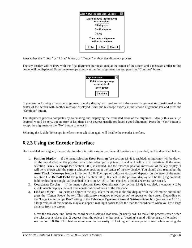
The Earth Centered Universe Pro V6.0 — User’s Manual Page 80
Press either the “1 Star” or “2 Star” button, or “Cancel” to abort the alignment process. The sky display will re-draw with the first alignment star positioned at the center of the screen and a message similar to that below will be displayed. Point the telescope exactly at the first alignment star and press the “Continue” button.
If you are performing a two-star alignment, the sky display will re-draw with the second alignment star positioned at the center of the screen with another message displayed. Point the telescope exactly at the second alignment star and press the “Continue” button. The alignment process completes by calculating and displaying the estimated error of the alignment. Ideally this value (in degrees) would be zero, but an error of last than 1 or 2 degrees usually produces a good alignment. Press the “Yes” button to accept the alignment or the “No” button to reject it. Selecting the Enable Telescope Interface menu selection again will disable the encoder interface.
6.2.3 Using the Encoder Interface Once enabled and aligned, the encoder interface is quite easy to use. Several functions are provided; each is described below.
1. Position Display — if the menu selection Show Position (see section 3.8.4) is enabled, an indicator will be drawn on the sky display at the position which the telescope is pointed to and will follow it in real-time. If the menu selection Track Telescope (see section 3.8.7) is enabled, and the telescope position moves out of the sky display, it will be re drawn with the current telescope position at the center of the sky display. You should also read about the Auto Track Telescope feature in section 3.8.8. The type of indicator displayed depends on the state of the menu selection Use Default Field Targets (see section 3.8.5). If checked, the position display will be the programmable field circles (or rectangle) as described in section 3.4.18.1. If not checked, a fixed size cross-hair is used.
2. Coordinate Display — if the menu selection Show Coordinates (see section 3.8.6) is enabled, a window will be visible which displays the real time equatorial coordinates of the telescope.
3. Find an Object — to locate an object in the sky, select the object in the sky display with the left mouse button and press the “Center Scope” button. This will cause a window (shown below) to appear on the screen. Depending on the “Large Center Scope Box” setting in the Telescope Type and General Settings dialog box (see section 3.8.15), a large version of this window may also appear, making it easier to see the read the coordinates when you are a large distance from the screen.
Move the telescope until both the coordinates displayed read zero (or nearly so). To make this process easier, when the telescope is closer than 2 degrees from the object in either axis, a “beeping” sound will be heard (if enabled — see section 3.8.16). This feature eliminates the necessity of looking at the computer screen while moving the
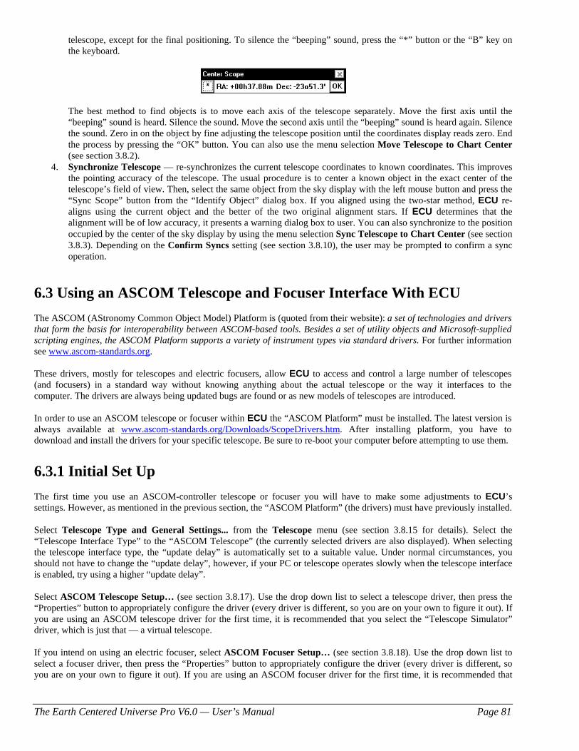
The Earth Centered Universe Pro V6.0 — User’s Manual Page 81
telescope, except for the final positioning. To silence the “beeping” sound, press the “*” button or the “B” key on the keyboard.
The best method to find objects is to move each axis of the telescope separately. Move the first axis until the
“beeping” sound is heard. Silence the sound. Move the second axis until the “beeping” sound is heard again. Silence the sound. Zero in on the object by fine adjusting the telescope position until the coordinates display reads zero. End the process by pressing the “OK” button. You can also use the menu selection Move Telescope to Chart Center (see section 3.8.2).
4. Synchronize Telescope — re-synchronizes the current telescope coordinates to known coordinates. This improves the pointing accuracy of the telescope. The usual procedure is to center a known object in the exact center of the telescope’s field of view. Then, select the same object from the sky display with the left mouse button and press the “Sync Scope” button from the “Identify Object” dialog box. If you aligned using the two-star method, ECU re-aligns using the current object and the better of the two original alignment stars. If ECU determines that the alignment will be of low accuracy, it presents a warning dialog box to user. You can also synchronize to the position occupied by the center of the sky display by using the menu selection Sync Telescope to Chart Center (see section 3.8.3). Depending on the Confirm Syncs setting (see section 3.8.10), the user may be prompted to confirm a sync operation.
6.3 Using an ASCOM Telescope and Focuser Interface With ECU The ASCOM (AStronomy Common Object Model) Platform is (quoted from their website): a set of technologies and drivers that form the basis for interoperability between ASCOM-based tools. Besides a set of utility objects and Microsoft-supplied scripting engines, the ASCOM Platform supports a variety of instrument types via standard drivers. For further information see www.ascom-standards.org. These drivers, mostly for telescopes and electric focusers, allow ECU to access and control a large number of telescopes (and focusers) in a standard way without knowing anything about the actual telescope or the way it interfaces to the computer. The drivers are always being updated bugs are found or as new models of telescopes are introduced. In order to use an ASCOM telescope or focuser within ECU the “ASCOM Platform” must be installed. The latest version is always available at www.ascom-standards.org/Downloads/ScopeDrivers.htm. After installing platform, you have to download and install the drivers for your specific telescope. Be sure to re-boot your computer before attempting to use them.
6.3.1 Initial Set Up The first time you use an ASCOM-controller telescope or focuser you will have to make some adjustments to ECU’s settings. However, as mentioned in the previous section, the “ASCOM Platform” (the drivers) must have previously installed. Select Telescope Type and General Settings... from the Telescope menu (see section 3.8.15 for details). Select the “Telescope Interface Type” to the “ASCOM Telescope” (the currently selected drivers are also displayed). When selecting the telescope interface type, the “update delay” is automatically set to a suitable value. Under normal circumstances, you should not have to change the “update delay”, however, if your PC or telescope operates slowly when the telescope interface is enabled, try using a higher “update delay”. Select ASCOM Telescope Setup… (see section 3.8.17). Use the drop down list to select a telescope driver, then press the “Properties” button to appropriately configure the driver (every driver is different, so you are on your own to figure it out). If you are using an ASCOM telescope driver for the first time, it is recommended that you select the “Telescope Simulator” driver, which is just that — a virtual telescope. If you intend on using an electric focuser, select ASCOM Focuser Setup… (see section 3.8.18). Use the drop down list to select a focuser driver, then press the “Properties” button to appropriately configure the driver (every driver is different, so you are on your own to figure it out). If you are using an ASCOM focuser driver for the first time, it is recommended that
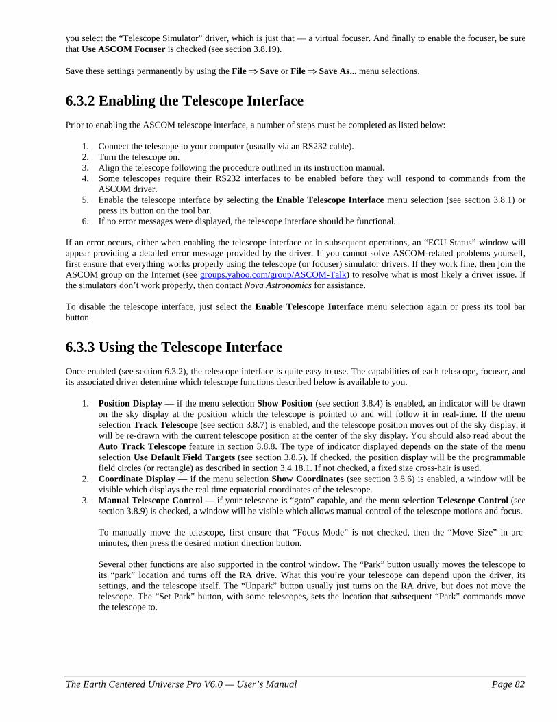
The Earth Centered Universe Pro V6.0 — User’s Manual Page 82
you select the “Telescope Simulator” driver, which is just that — a virtual focuser. And finally to enable the focuser, be sure that Use ASCOM Focuser is checked (see section 3.8.19). Save these settings permanently by using the File ⇒ Save or File ⇒ Save As... menu selections.
6.3.2 Enabling the Telescope Interface Prior to enabling the ASCOM telescope interface, a number of steps must be completed as listed below:
1. Connect the telescope to your computer (usually via an RS232 cable). 2. Turn the telescope on. 3. Align the telescope following the procedure outlined in its instruction manual. 4. Some telescopes require their RS232 interfaces to be enabled before they will respond to commands from the
ASCOM driver. 5. Enable the telescope interface by selecting the Enable Telescope Interface menu selection (see section 3.8.1) or
press its button on the tool bar. 6. If no error messages were displayed, the telescope interface should be functional.
If an error occurs, either when enabling the telescope interface or in subsequent operations, an “ECU Status” window will appear providing a detailed error message provided by the driver. If you cannot solve ASCOM-related problems yourself, first ensure that everything works properly using the telescope (or focuser) simulator drivers. If they work fine, then join the ASCOM group on the Internet (see groups.yahoo.com/group/ASCOM-Talk) to resolve what is most likely a driver issue. If the simulators don’t work properly, then contact Nova Astronomics for assistance. To disable the telescope interface, just select the Enable Telescope Interface menu selection again or press its tool bar button.
6.3.3 Using the Telescope Interface Once enabled (see section 6.3.2), the telescope interface is quite easy to use. The capabilities of each telescope, focuser, and its associated driver determine which telescope functions described below is available to you.
1. Position Display — if the menu selection Show Position (see section 3.8.4) is enabled, an indicator will be drawn on the sky display at the position which the telescope is pointed to and will follow it in real-time. If the menu selection Track Telescope (see section 3.8.7) is enabled, and the telescope position moves out of the sky display, it will be re-drawn with the current telescope position at the center of the sky display. You should also read about the Auto Track Telescope feature in section 3.8.8. The type of indicator displayed depends on the state of the menu selection Use Default Field Targets (see section 3.8.5). If checked, the position display will be the programmable field circles (or rectangle) as described in section 3.4.18.1. If not checked, a fixed size cross-hair is used.
2. Coordinate Display — if the menu selection Show Coordinates (see section 3.8.6) is enabled, a window will be visible which displays the real time equatorial coordinates of the telescope.
3. Manual Telescope Control — if your telescope is “goto” capable, and the menu selection Telescope Control (see section 3.8.9) is checked, a window will be visible which allows manual control of the telescope motions and focus.
To manually move the telescope, first ensure that “Focus Mode” is not checked, then the “Move Size” in arc-
minutes, then press the desired motion direction button.
Several other functions are also supported in the control window. The “Park” button usually moves the telescope to its “park” location and turns off the RA drive. What this you’re your telescope can depend upon the driver, its settings, and the telescope itself. The “Unpark” button usually just turns on the RA drive, but does not move the telescope. The “Set Park” button, with some telescopes, sets the location that subsequent “Park” commands move the telescope to.
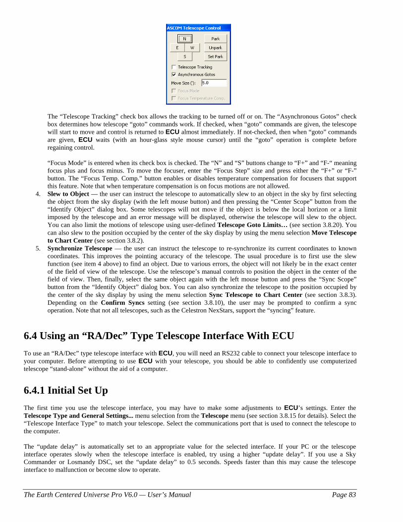
The Earth Centered Universe Pro V6.0 — User’s Manual Page 83
The “Telescope Tracking” check box allows the tracking to be turned off or on. The “Asynchronous Gotos” check
box determines how telescope “goto” commands work. If checked, when “goto” commands are given, the telescope will start to move and control is returned to ECU almost immediately. If not-checked, then when “goto” commands are given, ECU waits (with an hour-glass style mouse cursor) until the “goto” operation is complete before regaining control.
“Focus Mode” is entered when its check box is checked. The “N” and “S” buttons change to “F+” and “F-“ meaning
focus plus and focus minus. To move the focuser, enter the “Focus Step” size and press either the “F+” or “F-” button. The “Focus Temp. Comp.” button enables or disables temperature compensation for focusers that support this feature. Note that when temperature compensation is on focus motions are not allowed.
4. Slew to Object — the user can instruct the telescope to automatically slew to an object in the sky by first selecting the object from the sky display (with the left mouse button) and then pressing the “Center Scope” button from the “Identify Object” dialog box. Some telescopes will not move if the object is below the local horizon or a limit imposed by the telescope and an error message will be displayed, otherwise the telescope will slew to the object. You can also limit the motions of telescope using user-defined Telescope Goto Limits… (see section 3.8.20). You can also slew to the position occupied by the center of the sky display by using the menu selection Move Telescope to Chart Center (see section 3.8.2).
5. Synchronize Telescope — the user can instruct the telescope to re-synchronize its current coordinates to known coordinates. This improves the pointing accuracy of the telescope. The usual procedure is to first use the slew function (see item 4 above) to find an object. Due to various errors, the object will not likely be in the exact center of the field of view of the telescope. Use the telescope’s manual controls to position the object in the center of the field of view. Then, finally, select the same object again with the left mouse button and press the “Sync Scope” button from the “Identify Object” dialog box. You can also synchronize the telescope to the position occupied by the center of the sky display by using the menu selection Sync Telescope to Chart Center (see section 3.8.3). Depending on the Confirm Syncs setting (see section 3.8.10), the user may be prompted to confirm a sync operation. Note that not all telescopes, such as the Celestron NexStars, support the “syncing” feature.
6.4 Using an “RA/Dec” Type Telescope Interface With ECU To use an “RA/Dec” type telescope interface with ECU, you will need an RS232 cable to connect your telescope interface to your computer. Before attempting to use ECU with your telescope, you should be able to confidently use computerized telescope “stand-alone” without the aid of a computer.
6.4.1 Initial Set Up The first time you use the telescope interface, you may have to make some adjustments to ECU’s settings. Enter the Telescope Type and General Settings... menu selection from the Telescope menu (see section 3.8.15 for details). Select the “Telescope Interface Type” to match your telescope. Select the communications port that is used to connect the telescope to the computer. The “update delay” is automatically set to an appropriate value for the selected interface. If your PC or the telescope interface operates slowly when the telescope interface is enabled, try using a higher “update delay”. If you use a Sky Commander or Losmandy DSC, set the “update delay” to 0.5 seconds. Speeds faster than this may cause the telescope interface to malfunction or become slow to operate.
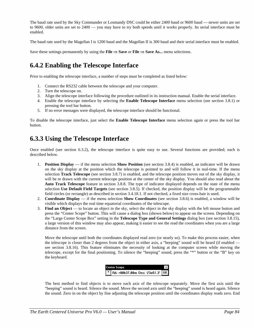
The Earth Centered Universe Pro V6.0 — User’s Manual Page 84
The baud rate used by the Sky Commander or Losmandy DSC could be either 2400 baud or 9600 baud — newer units are set to 9600, older units are set to 2400 — you may have to try both speeds until it works properly. Its serial interface must be enabled. The baud rate used by the Magellan I is 1200 baud and the Magellan II is 300 baud and their serial interface must be enabled. Save these settings permanently by using the File ⇒ Save or File ⇒ Save As... menu selections.
6.4.2 Enabling the Telescope Interface Prior to enabling the telescope interface, a number of steps must be completed as listed below:
1. Connect the RS232 cable between the telescope and your computer. 2. Turn the telescope on. 3. Align the telescope interface following the procedure outlined in its instruction manual. Enable the serial interface. 4. Enable the telescope interface by selecting the Enable Telescope Interface menu selection (see section 3.8.1) or
pressing the tool bar button. 5. If no error messages were displayed, the telescope interface should be functional.
To disable the telescope interface, just select the Enable Telescope Interface menu selection again or press the tool bar button.
6.3.3 Using the Telescope Interface Once enabled (see section 6.3.2), the telescope interface is quite easy to use. Several functions are provided; each is described below.
1. Position Display — if the menu selection Show Position (see section 3.8.4) is enabled, an indicator will be drawn on the sky display at the position which the telescope is pointed to and will follow it in real-time. If the menu selection Track Telescope (see section 3.8.7) is enabled, and the telescope position moves out of the sky display, it will be re drawn with the current telescope position at the center of the sky display. You should also read about the Auto Track Telescope feature in section 3.8.8. The type of indicator displayed depends on the state of the menu selection Use Default Field Targets (see section 3.8.5). If checked, the position display will be the programmable field circles (or rectangle) as described in section 3.4.18.1. If not checked, a fixed size cross-hair is used.
2. Coordinate Display — if the menu selection Show Coordinates (see section 3.8.6) is enabled, a window will be visible which displays the real time equatorial coordinates of the telescope.
3. Find an Object — to locate an object in the sky, select the object in the sky display with the left mouse button and press the “Center Scope” button. This will cause a dialog box (shown below) to appear on the screen. Depending on the “Large Center Scope Box” setting in the Telescope Type and General Settings dialog box (see section 3.8.15), a large version of this window may also appear, making it easier to see the read the coordinates when you are a large distance from the screen.
Move the telescope until both the coordinates displayed read zero (or nearly so). To make this process easier, when the telescope is closer than 2 degrees from the object in either axis, a “beeping” sound will be heard (if enabled — see section 3.8.16). This feature eliminates the necessity of looking at the computer screen while moving the telescope, except for the final positioning. To silence the “beeping” sound, press the “*” button or the “B” key on the keyboard.
The best method to find objects is to move each axis of the telescope separately. Move the first axis until the
“beeping” sound is heard. Silence the sound. Move the second axis until the “beeping” sound is heard again. Silence the sound. Zero in on the object by fine adjusting the telescope position until the coordinates display reads zero. End

The Earth Centered Universe Pro V6.0 — User’s Manual Page 85
the process by pressing the “OK” button. You can also use the menu selection Move Telescope to Chart Center (see section 3.7.2).
Note that, unlike some other telescope interfaces, the Magellan and Sky Commander/Losmandy DSC do not support “syncing,” via the serial interface, on an object to improve pointing accuracy, but may support “syncing” using their built-in keypad.
The Earth Centered Universe Pro V6.0 — User’s Manual Page 86
Appendix — Guide Star Catalog Info
Note for Earth Centered Universe Users
Nova Astronomics has obtained a license from the Space Telescope Science Institute to reproduce data from the Guide Star Catalog. As a requirement of the agreement, Nova Astronomics is required to provide this reproduction of the original printed booklet included with the original CD-ROM set. Several changes have been made to the Guide Star Catalog (GSC) Version 1.1 to produce the "Earth Centered Universe" CD-ROM that may make some information in this booklet slightly incorrect. Details of these changes and other important information regarding the Guide Star Catalog are included in the text file: “README.GSC” located in the root directory of the ECU CD-ROM.
THE GUIDE STAR CATALOG VERSION 1.1
An all-sky astrometric and photometric catalog to support
the operation of the Hubble Space Telescope
Copyright (c) 1989, 1992, The Association of Universities for Research in Astronomy, Inc. This set of two CD-ROMs in the ISO 9660 format contains the Guide Star Catalog — Version 1.1, with an issue date of 1 August 1992. The Guide Star Catalog (GSC) was prepared by the Space Telescope Science Institute (ST ScI), 3700 San Martin Drive, Baltimore, MD 21218, USA. ST ScI is operated by the Association of Universities for Research in Astronomy, Inc. (AURA), under contract with the National Aeronautics and Space Administration (NASA).
1. INTRODUCTION The Guide Star Catalog (GSC), which has been constructed to support the operational need of the Hubble Space Telescope (HST) for off-axis guide stars, contains nearly 19 million objects brighter than sixteenth magnitude, of which more than 15 million are classified as stars. The original version of this catalog, GSC 1.0, is described in a series of papers: Lasker et al. (1990); Russell et al. (1990); and Jenkner et al. (1990); hereafter referred to as Papers I, II, and III. Additions and corrections made in GSC 1.1 address
incompleteness, misnomers, artifacts, and other errors due to the overexposure of the brighter stars on the Schmidt plates,
the identification of blends likely to have been incorrectly resolved, the incorporation of errata reported by the user-community or identified by the analysis of HST operational problems.
Among the primary authors of the GSC 1.0 and the associated systems, the scientific responsibilities were divided as follows: Helmut Jenkner, system coordination and overall design; Barry M. Lasker, astrophysics and photometry; Brian J. McLean, algorithmic analysis and systems development; Jane L. Russell, astrometry; Michael M. Shara, system management; and Conrad R. Sturch, production management and quality control. GSC 1.1 analysis and production were performed primarily by Jesse B. Doggett, Daniel Egret, Brian J. McLean, and Conrad R. Sturch. Helmut Jenkner is on assignment from the European Space Agency; Jane L. Russell is currently affiliated with the Applied Research Corporation, Landover, MD; and Conrad R. Sturch is with the Astronomy Programs, Computer Sciences Corporation at Space Telescope Science Institute. Daniel Egret is affiliated with Observatoire de Strasbourg, France.
2. DISCUSSION OF THE GSC 1.0 PROJECT
Astronomical and Algorithmic Foundation As described in Paper I, the GSC is primarily based on an all-sky, single epoch, single passband collection of Schmidt plates. For centers at +6 degrees and north, a 1982 epoch "Quick V" survey was obtained by the Palomar Observatory, while for southern fields, materials from the UK SERC J survey (epoch approximately 1975) and its equatorial extension (epoch approximately 1982) were used. In addition, over 100 short-exposure plates were taken with the Palomar Oschin and UK Schmidt telescopes to cover complex regions including the southern Milky Way, the Magellanic Clouds, and M31. These northern, southern, and supplemental plates hereafter are referred to as N, S, and X plates, respectively. The plates were digitized into 14000-square rasters at 25 um sample intervals using modified PDS microdensitometers. The sky-background was modeled with a bi-dimensional cubic spline approximation to the modal level. Then an object finder, based on locating connected pixels at a certain threshold above the background, was used to obtain, for each plate, a
The Earth Centered Universe Pro V6.0 — User’s Manual Page 87
list of positions, sizes, intensities, and related descriptive parameters. Images with multiple peaks were deblended by an algorithm based on correlations against a library of stellar images. The identified objects were classified as stars or non-stars by an interactive multivariate Bayesian classifier that used image features from the object-detection steps and was started from a small set of objects visually identified on each plate. Comparison of classifications from multiply cataloged objects in the plate overlap areas shows that the purity of objects classified as stars is typically 97 percent.
Photometric and Astrometric Calibrations The GSC calibrations were obtained on a plate-by-plate basis by polynomial modeling against the photometric and astrometric reference catalogs. Photometry is available in the natural systems defined by the individual plates in the GSC collection (generally J or V), and the calibrations are done using B, V standards from the Guide Star Photometric Catalog (Lasker, Sturch, et al. 1988). In Paper II the overall quality of the photometry near the standard stars was estimated from the fits and other tests to be 0.15 mag (one sigma, averaged over all plates), while the quality far from the sequences was estimated from the all-sky plate-to-plate agreement and from comparisons with independent photometric surveys to be about 0.3 mag (one sigma), with about 10% of the errors being greater than 0.5 mag. Additionally, Ratnatunga's (1990) comparison of the GSC against totally independent J-band photographic photometry for three southern fields (20 sq deg area) for 12.5 < J < 15.5 shows agreement at the 0.1-0.2 mag level. Astrometry, at equinox J2000, is available at the epochs of the individual plates used in the GSC; and the reductions to the reference catalogs (AGK3, SAOC, or CPC, depending on the declination zone) use third order expansions of the modeled plate and telescope effects. The fits to the reference catalogs lie in the range 0.5" to 0.9", and most of this is attributable to errors in the reference catalogs, to centroiding errors on the relatively large images of the reference stars, and to unmodeled astrometric effects. Paper II reported estimates of the overall external astrometric error, produced by comparisons of independently measured positions, in the range 0.2" to 0.8" (per coordinate), depending on the areas of the plate and the sky. Then from a more extensive analysis against the Carlsberg Automatic Meridian Circle data, Taff et al. (1990) found that GSC absolute positional errors from plate center to edge vary from 0.5" to 1.1" in the north and from 1.0" to 1.6" in the south, and that relative errors at half-degree separations range from 0.33" to 0.76" depending upon hemisphere and magnitude.
Production, Database Organization, and Population Statistics Paper III describes the software system used to produce the GSC. It consisted of a set of (primarily non-interactive) image-processing and calibration programs interconnected by a set of pipeline files and supported by databases organized on a plate-by-plate basis. A set of utility programs was also provided to support quality control and to correct operational problems. Object names are of the form GSC rrrrr nnnnn, where the first field specifies an internal region number and the second is an ordinal within it. For objects cataloged from more than one photographic plate, an entry was made from each image; and all entries for the same object were given the same unique name. Paper III also reviews the database for compiling statistics of objects with multiple entries and the details of the organization and structure of the GSC, including the provisions for assigning unique names, for cataloging objects lying in the plate overlap regions, for rapidly indexing positions against regions, and for recovering the original plate measurements. The separate count statistics for stellar and non-stellar objects on a plate-by-plate basis are provided in the supporting tables.
User Interfaces, Utilities, and Astronomical Applications
The all-sky collection of Schmidt plates that were digitized, archived to optical disc, and processed to generate the Guide Star Catalog (GSC) constitute a general image resource for astronomical research. This data set, combined with the computing environment provided by the Guide Star Astrometric Support Package (GASP), major elements of which are exported within the Space Telescope Science Data Analysis System, provides random access to a digital image in any part of the sky. The GASP environment also supports access to the GSC and to other major astronomical catalogs.
3. REVISIONS IN GSC 1.1
The GSC 1.1 activities performed to address a number of known problems in GSC 1.0 are summarized here and described in detail in the text file for this revision, REV_1_1.TBL;1. Two concerns related to the brighter stars arise from the heavily overexposed images on the Schmidt plates used in the GSC, namely an incompleteness and a reduced precision. Both are addressed in the domain V < 7.5 by the use of data from
The Earth Centered Universe Pro V6.0 — User’s Manual Page 88
the INCA Data Base (Turon et al. 1992; Jahreiss et al. 1992; Grenon et al. 1992) in the Tycho Input Catalog (TIC; Egret et al. 1992). Such entries are designated by the plate identifier +056 in GSC 1.1. The limit of V < 7.5 preserves the original GSC data for objects that were used in the GSC 1.0 astrometric calibration. Naming errors occur when objects catalogued from more than one photographic plate have positional errors sufficiently large that crossmatching of the overlapping plate areas is done incorrectly. The most significant known instances of this in GSC 1.0 were associated with overexposed (and therefore badly centroided) images of the brighter stars. A search around the positions of the INCA stars facilitated the identification of these naming errors, which were then removed in GSC 1.1. GSC 1.0 contains many pairs of objects (from single plates) with separations significantly smaller than the expected resolution of the catalog, which Garnavich (1991), based on a study of four northern plates, estimates at ~ 10" for 8.0 < V < 14.0. Visual inspection shows that these are generally blends that have been properly resolved, but then affected by a centroider defect that made the separations artificially small. Such components of blends with incorrect separations are given a classification of 2 (blend; cf. the text file for a full listing of the codes). For stars with V < 8, image-processing artifacts near the diffraction spikes exist in GSC 1.0. In GSC 1.1, potential artifacts were identified by use of a purely geometrical criterion (proximity of the object to the spike), and were assigned a classification of 5. Small areas around southern stars brighter than V ~ 3 are not processed from the Schmidt plates and were left blank in GSC 1.0. For these, GSC 1.1 contains entries from supplemental astrograph plates taken with the GPO (Gran Prisma Objectif) telescope on La Silla, and the astrograph at the Black Birch Observatory (BBO) in Blenheim, New Zealand. Because of their smaller fields, the photometric and astrometric calibrations of data from most GPO and a few BBO plates were performed against nearby GSC entries based on the Schmidt plates. A number of specific errors in GSC 1.0 have been identified by the user-community and by analyses of HST operational problems. These generally involve naming errors, plate flaws, misclassifications, and multiple stars; most are individually corrected in GSC 1.1. Also, the photometric error parameter in GSC 1.1 is now correctly described by equation (3) in Paper II; i.e., the erratum of footnote 5 therein is no longer pertinent Plans for GSC maintenance beyond version 1.1 include an astrometric recalibration (cf. Taff, Lattanzi, and Bucciarelli 1990), and investigation of erroneous double entries that may exist for V > 7.5.
4. ORGANIZATION OF THE DATA FILES The Guide Star Catalog is subdivided into regions that are bounded by small circles of right ascension and great circles of declination, and that are numbered consecutively from 0001 to 9537. Data for each region are stored as separate files; these files are contained in directories, each of which subtends a 7.5 degree zone of declination. The Guide Star Catalog is distributed as a two CD-ROM set, divided at a declination of -7.5 degrees. An introductory file (README.TXT;1) and the supporting tables are duplicated on both discs. All data files (i.e., with the exception of the file README.TXT;1 and the directory files) are in FITS (Flexible Image Transport System; Greisen et al. 1981; Wells et al. 1981; Grosbol et al. 1988; and Jahreiss et al. 1992) table format. The root directory contains the following files: README.TXT;1 - Introduction. GSC - Directory for GSC region files. TABLES - Directory for GSC supporting tables. Directory GSC contains directories for the 7.5 degree zones in declination; these directories in turn contain the GSC region files in FITS format for the respective zone, with file identifiers of the form nnnn.GSC;1, where nnnn is the 4-digit decimal region number, with leading zeroes used as required to fill the field. The directories are named as follows: Directory Declination Regions Disc From To From To N0000 +00D 00' +07D 30' 0001 0593 1 N0730 +07D 30' +15D 00' 0594 1177 1 N1500 +15D 00' +22D 30' 1178 1728 1 N2230 +22D 30' +30D 00' 1729 2258 1 N3000 +30D 00' +37D 30' 2259 2780 1 N3730 +37D 30' +45D 00' 2781 3245 1 N4500 +45D 00' +52D 30' 3246 3651 1 N5230 +52D 30' +60D 00' 3652 4013 1 N6000 +60D 00' +67D 30' 4014 4293 1 N6730 +67D 30' +75D 00' 4294 4491 1 N7500 +75D 00' +82D 3€0' 4492 4614 1 N8230 +82D 30' +90D 00' 4615 4662 1 S0000 -00D 00' -07D 30' 4663 5259 2
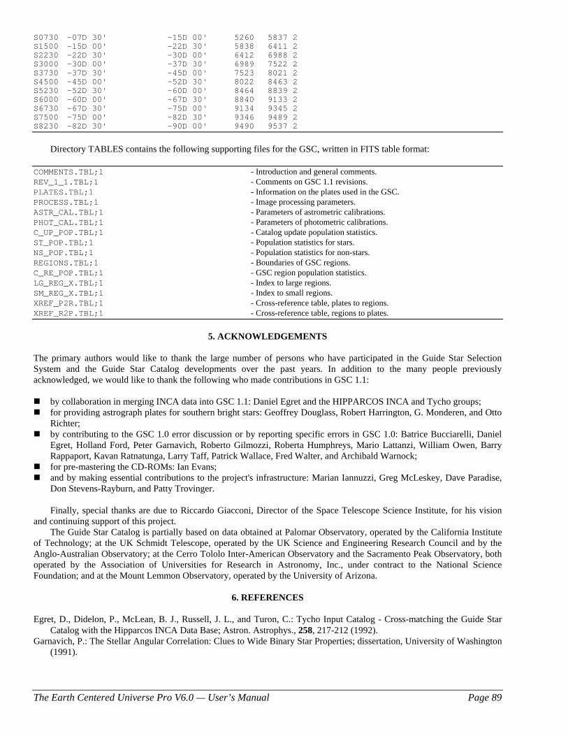
The Earth Centered Universe Pro V6.0 — User’s Manual Page 89
S0730 -07D 30' -15D 00' 5260 5837 2 S1500 -15D 00' -22D 30' 5838 6411 2 S2230 -22D 30' -30D 00' 6412 6988 2 S3000 -30D 00' -37D 30' 6989 7522 2 S3730 -37D 30' -45D 00' 7523 8021 2 S4500 -45D 00' -52D 30' 8022 8463 2 S5230 -52D 30' -60D 00' 8464 8839 2 S6000 -60D 00' -67D 30' 8840 9133 2 S6730 -67D 30' -75D 00' 9134 9345 2 S7500 -75D 00' -82D 30' 9346 9489 2 S8230 -82D 30' -90D 00' 9490 9537 2
Directory TABLES contains the following supporting files for the GSC, written in FITS table format: COMMENTS.TBL;1 - Introduction and general comments. REV_1_1.TBL;1 - Comments on GSC 1.1 revisions. PLATES.TBL;1 - Information on the plates used in the GSC. PROCESS.TBL;1 - Image processing parameters. ASTR_CAL.TBL;1 - Parameters of astrometric calibrations. PHOT_CAL.TBL;1 - Parameters of photometric calibrations. C_UP_POP.TBL;1 - Catalog update population statistics. ST_POP.TBL;1 - Population statistics for stars. NS_POP.TBL;1 - Population statistics for non-stars. REGIONS.TBL;1 - Boundaries of GSC regions. C_RE_POP.TBL;1 - GSC region population statistics. LG_REG_X.TBL;1 - Index to large regions. SM_REG_X.TBL;1 - Index to small regions. XREF_P2R.TBL;1 - Cross-reference table, plates to regions. XREF_R2P.TBL;1 - Cross-reference table, regions to plates.
5. ACKNOWLEDGEMENTS The primary authors would like to thank the large number of persons who have participated in the Guide Star Selection System and the Guide Star Catalog developments over the past years. In addition to the many people previously acknowledged, we would like to thank the following who made contributions in GSC 1.1:
by collaboration in merging INCA data into GSC 1.1: Daniel Egret and the HIPPARCOS INCA and Tycho groups; for providing astrograph plates for southern bright stars: Geoffrey Douglass, Robert Harrington, G. Monderen, and Otto
Richter; by contributing to the GSC 1.0 error discussion or by reporting specific errors in GSC 1.0: Batrice Bucciarelli, Daniel
Egret, Holland Ford, Peter Garnavich, Roberto Gilmozzi, Roberta Humphreys, Mario Lattanzi, William Owen, Barry Rappaport, Kavan Ratnatunga, Larry Taff, Patrick Wallace, Fred Walter, and Archibald Warnock;
for pre-mastering the CD-ROMs: Ian Evans; and by making essential contributions to the project's infrastructure: Marian Iannuzzi, Greg McLeskey, Dave Paradise,
Don Stevens-Rayburn, and Patty Trovinger. Finally, special thanks are due to Riccardo Giacconi, Director of the Space Telescope Science Institute, for his vision and continuing support of this project. The Guide Star Catalog is partially based on data obtained at Palomar Observatory, operated by the California Institute of Technology; at the UK Schmidt Telescope, operated by the UK Science and Engineering Research Council and by the Anglo-Australian Observatory; at the Cerro Tololo Inter-American Observatory and the Sacramento Peak Observatory, both operated by the Association of Universities for Research in Astronomy, Inc., under contract to the National Science Foundation; and at the Mount Lemmon Observatory, operated by the University of Arizona.
6. REFERENCES Egret, D., Didelon, P., McLean, B. J., Russell, J. L., and Turon, C.: Tycho Input Catalog - Cross-matching the Guide Star
Catalog with the Hipparcos INCA Data Base; Astron. Astrophys., 258, 217-212 (1992). Garnavich, P.: The Stellar Angular Correlation: Clues to Wide Binary Star Properties; dissertation, University of Washington
(1991).
The Earth Centered Universe Pro V6.0 — User’s Manual Page 90
Greisen, E. W., Harten, R. H.: An Extension of FITS for Groups of Small Arrays of Data; Astron. Astrophys. Suppl. Ser., 44, 371-374 (1981).
Grenon, M., Mermilliod, M., Mermilliod, J. C.: The Hipparcos Input Catalogue. III. Photometry; Astron. Astrophys., 258, 88-93 (1992).
Grosbol, P., Harten, R. H., Greisen, E. W., Wells, D. C.: Generalized Extensions and Blocking Factors for FITS; Astron. Astrophys. Suppl. Ser., 73, 359-364 (1988).
Harten, R. H., Grosbol, P., Greisen, E. W., Wells, D. C.: The FITS Tables Extension; Astron. Astrophys. Suppl. Ser., 73, 365-372 (1988).
Jahreiss, H., Requieme, Y., Argue, A. N., Dommanget, J., Rousseau, M., Lederle, T., Le Poole, R. S., Mazurier, J. M., Morrison, L. V., Nys, O., Penston, M. J., Perie, J. P., Prevot, L., Tucholke, H. J., de Vegt, C.: The Hipparcos Input Catalogue. II. Astrometric Data; Astron. Astrophys., 258, 82-87 (1992).
Jenkner, H., Lasker, B. M., Sturch, C. R., McLean, B. J., Shara, M. M., Russell, J. L.: The Guide Star Catalog. III. Production, Database Organization, and Population Statistics; Astron. J., 99, 2081-2154 (1990).
Lasker, B. M., Sturch, C. R., Lopez, C., Mallama, A. D., McLaughlin, S. F., Russell, J. L., Wisniewski, W. Z., Gillespie, B. A., Jenkner, H., Siciliano, E. D., Kenny, D., Baumert, J. H., Goldberg, A. M., Henry, G. W., Kemper, E., Siegel, M. J.: The Guide Star Photometric Catalog. I.; Astrophys. J. Suppl., 68, 1-90 (1988).
Lasker, B. M., Sturch, C. R., McLean, B. J., Russell, J. L., Jenkner, H., Shara, M. M.: The Guide Star Catalog. I. Astronomical and Algorithmic Foundations; Astron. J., 99, 2019-2058 (1990).
Ratnatunga, K. U.: Comparison of GSC Photometry in Three Southern Fields; Astron. J., 100, 280-290 (1990). Russell, J. L., Lasker, B. M., McLean, B. J., Sturch, C. R., Jenkner, H.: The Guide Star Catalog. II. Photometric and
Astrometric Calibrations; Astron. J., 99, 2059-2081 (1990). Taff, L. G., Lattanzi, M. G., Bucciarelli, B.: Two Successful Techniques for Schmidt Plate Astrometry; Astrophys. J., 358,
359-369 (1990). Taff, L. G., Lattanzi, M. G., Bucciarelli, B., Gilmozzi, R., McLean, B. J., Jenkner, H., Laidler, V. G., Lasker, B. M., Shara,
M. M., Sturch, C. R.: Some Comments on the Astrometric Properties of the Guide Star Catalog; Astrophys. J., 353, L45-L48 (1990).
Turon, C., Gomez, A., Crifo, F., Creze, M., Perryman, M. A. C., Morin, D., Arenou, F., Nicolet, B., Chareton, M., Egret, D.: The Hipparcos Input Catalogue. I. Star Selection; Astron. Astrophys., 258, 74-81 (1992).
Wells, D. C., Greisen, E. W., Harten, R. H.: FITS - A Flexible Image Transport System; Astron. Astrophys. Suppl. Ser., 44, 363-370 (1981).

The Earth Centered Universe Pro V6.0 — User’s Manual Page 91
About the Author David J. Lane has been an active amateur astronomer since the early 1980s and is a life member of the Royal Astronomical Society of Canada (RASC). He is employed as the Astronomy Technician and High-Performance Computing Systems Administrator at the Department of Astronomy and Physics at Saint Mary’s University in Halifax, Nova Scotia, Canada. Dave often appears in the local and Canadian national media covering astronomical topics of interest to the general public. His primary astronomical interests are in variable star observing, observatory automation, CCD imaging, deep sky observing, and of course, using computers and the Internet in Astronomy. He built and operates the Abbey Ridge Observatory in his backyard (see www.davelane.ca/aro). He also volunteers his time on a variety of projects of the Royal Astronomical Society of Canada (RASC). He was the national president of the RASC from 2008-2010. Dave holds the distinction, along with Paul Gray, of being the first Canadians to discover a supernova (1995F in NGC 2726) from within Canada — this occurring in February of 1995. Earth Centered Universe was controlling the telescope used to discover the supernova. He has since discovered three more supernovae (2005B, 2005ea with Paul Gray and 2010lt with Kathryn and Paul Gray). Asteroid 117032 has been named “Davidlane” For his service and achievments, the RASC has awarded Dave the Chant Medal, Service Medal and Ken Chilton Prize (twice). The Chant Medal of the Royal Astronomical Society of Canada is the highest award for amateur contributions to astronomy in Canada. Nova Astronomics is Dave’s part-time business, which was primarily formed to support the development and distribution of this software.


![Manual nova ortografia[1]](https://img.pdfslide.us/doc/110x75/54997ce0ac7959ff2d8b58d1/manual-nova-ortografia1.jpg)