Embed Size (px)
Citation preview
Version 3.0.0.600 1 ALNET SYSTEMS
NET PROFESSIONAL user's manual
User's manual version 3.0 (January 2012)
This manual applies to program version NET PROFFESIONAL 3.0.0.600
Version 3.0.0.600 2 ALNET SYSTEMS
Contents
1. Introduction ............................................................................................................................... 5
1.1 System description ............................................................................................................ 5
1.2 Video capture cards ........................................................................................................ 5
1.3 System and hardware requirements ........................................................................... 6
2. Installation of the system ....................................................................................................... 7
2.1 Video capture cards installation .................................................................................. 7
2.2 Installing USB dongle ........................................................................................................ 7
2.3 Connecting cameras....................................................................................................... 8
2.4 Software installation ......................................................................................................... 8
3.1 Running the program for the first time ........................................................................ 9
3.1.1 Configuration Wizard ................................................................................................ 9
3.1.1.2 Regional settings ................................................................................................... 10
3.1.2 System administrator ............................................................................................... 17
3.2 Main Program Window .................................................................................................. 18
3.2.1 Camera view ............................................................................................................ 21
3.3 Scheduler ........................................................................................................................... 23
3.3.1 Cameras schedule .................................................................................................. 25
3.3.2 Sounds schedule ...................................................................................................... 26
3.3.3 Alarm inputs schedule ............................................................................................ 26
3.3.4 System alerts .............................................................................................................. 27
3.3.5 Scheduler – Address book ..................................................................................... 27
3.3 Camera configuration ................................................................................................... 29
3.3.1 ANALOGUE SYSTEM CAMERA CONFIGURATION ............................................. 30
3.3.1.1 Camera ................................................................................................................... 30
3.3.1.2 Resolution ................................................................................................................ 32
3.3.1.3 Compression .......................................................................................................... 33
3.3.2 IP CAMERA CONFIGURATION ............................................................................... 33
3.3.2.1 Resolution ................................................................................................................ 35
3.3.2.2 Card ......................................................................................................................... 36
3.3.2.3 Network ................................................................................................................... 37
3.3.2.4 Compression .......................................................................................................... 38
3.3.2.5 Advanced .............................................................................................................. 40
3.3.3 Common configuration settings .......................................................................... 41
3.3.3.1 Frame rate .............................................................................................................. 41
3.3.3.2 Motion ...................................................................................................................... 42
Version 3.0.0.600 3 ALNET SYSTEMS
3.3.3.3 Recording ............................................................................................................... 43
3.3.3.4 Dome ....................................................................................................................... 45
3.3.3.5 Sound ....................................................................................................................... 46
3.3.3.6 Alarms ...................................................................................................................... 47
3.3.3.7 Server........................................................................................................................ 48
3.4 Sound configuration ....................................................................................................... 49
3.4.1 Format ......................................................................................................................... 50
3.4.2 Recording ................................................................................................................... 51
3.4.2 Alarms .......................................................................................................................... 52
3.5 Alarm inputs ...................................................................................................................... 52
3.6 Output switches ............................................................................................................... 54
3.7 Network services .............................................................................................................. 55
3.7.1 Video server ............................................................................................................... 55
3.7.2 Http .............................................................................................................................. 56
3.7.3 Video for Java .......................................................................................................... 60
3.7.4 Dial up ......................................................................................................................... 60
3.7.5 Backup ........................................................................................................................ 61
3.8 Archive storage ............................................................................................................... 61
3.9 User accounts settings ................................................................................................... 62
3.9.1 User list ......................................................................................................................... 62
3.9.2 Synchronization ........................................................................................................ 65
3.9.3 Other – inactivity log off ......................................................................................... 66
3.10 Dome control ................................................................................................................. 67
3.10.1 Setting the parameters and protocols of the domes ................................. 67
3.10.2 Dome control panel ............................................................................................. 70
3.11 E-map editor ................................................................................................................... 70
3.12 Program settings ............................................................................................................ 73
3.12.1 Mail ............................................................................................................................ 73
3.12.2 Photos ....................................................................................................................... 74
3.12.3 Event log .................................................................................................................. 75
3.12.4 Snapshots ................................................................................................................. 76
3.12.5 Display ....................................................................................................................... 76
3.12.6 System settings ........................................................................................................ 77
3.12.6 Database settings .................................................................................................. 78
3.13 External Tools .................................................................................................................. 79
3.14 Save configuration ....................................................................................................... 79
Version 3.0.0.600 4 ALNET SYSTEMS
3.15 USB dongle update ...................................................................................................... 79
4. System Tools ............................................................................................................................ 80
4.1 Browse archives ............................................................................................................... 80
4.1.1 Searching for motion in the archive recordings ............................................. 82
4.1.2 Export to .avi .............................................................................................................. 82
4.1.3 Backup copy ............................................................................................................. 83
4.1.4 Watermark check .................................................................................................... 87
4.2 Photo browser .................................................................................................................. 88
4.3 Registering domain ......................................................................................................... 89
4.4 Dynamic layout ............................................................................................................... 90
4.5 Watermark export ........................................................................................................... 91
4.6 Program console ............................................................................................................. 92
4.7 Import/Export of program configuration .................................................................. 93
4.7.1 Configuration export .............................................................................................. 94
4.7.2 Configuration Import .............................................................................................. 94
4.8 Log browser ...................................................................................................................... 94
4.9 Keyboard shortcuts ......................................................................................................... 95
Version 3.0.0.600 5 ALNET SYSTEMS
1. Introduction
We present to you next version of NET PROFESSIONAL system with many new
functions and modules. Many of these changes are the effect of our cooperation with
You and our Partners. Part of them are our ideas which extend capabilities of digital
video recording. Please pay your attention to the possibilities of simultaneous image
recording from network cameras and, widely used so far, analogue cameras,
developed archives and wider capabilities of controlling the whole system.
1.1 System description
NET PROFESSIONAL is a digital video recorder designed for cooperation with CCTV
cameras. It uses PC class computers which work under control of Microsoft Windows
VISTA / 7 32 Bit operating system. New NET PROFESSIONAL system version can record
image from up to 32 cameras, servicing 32 output switches and 32 alarm inputs.
Moreover the system can be hybrid that is one system can service both analogue an IP
cameras – thanks to this it is possible to upgrade an existing installation and add IP or
analogue cameras. Managing the video server through the network is possible. Program
allows wide possibilities of motion detection settings, searching the motion in archives,
servicing alarm events. Differential image-compression method guarantees image
recording longer than in other systems of that type without changing the image quality
and storage space.
Software for managing NET PROFESSIONAL system consists of two independent
applications:
1. NET PROFESSIONAL (Video Digital Recording - Server)
2. CMS (Client Mobile Software – Client)
The first application is a server: processes image from the cameras, manages user
accounts, tasks, controls the cameras. The second one is used as a client. We can
connect to the server by a local network and do remote monitoring. Client application is
available on mobile device (mobile phones, Pocket PC, Tablets) which allows access to
camera images from any place in the world. Every installation of mobile application you
will find in this link http://mobi.alnetsystems.com/
1.2 Video capture cards
Video capture cards are mainboard extension placed inside the computer chassis. They
use commonly accessible PCI, PCIe x interface on mainboards. Current technology
allows image processing from 25 up to 400 frames per second for one card in PAL system.
Version 3.0.0.600 6 ALNET SYSTEMS
Whole specification of available devices can be found on our website
www.alnetsystems.com .
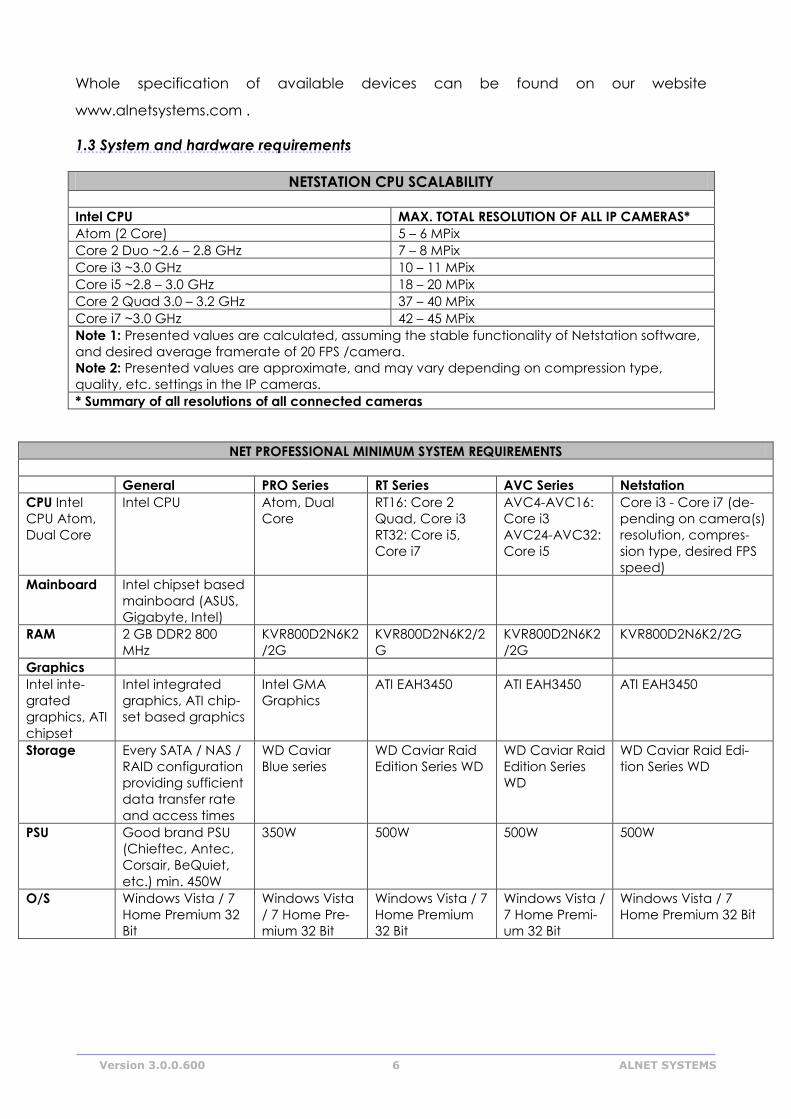
1.3 System and hardware requirements
NETSTATION CPU SCALABILITY
Intel CPU MAX. TOTAL RESOLUTION OF ALL IP CAMERAS*
Atom (2 Core) 5 – 6 MPix
Core 2 Duo ~2.6 – 2.8 GHz 7 – 8 MPix
Core i3 ~3.0 GHz 10 – 11 MPix
Core i5 ~2.8 – 3.0 GHz 18 – 20 MPix
Core 2 Quad 3.0 – 3.2 GHz 37 – 40 MPix
Core i7 ~3.0 GHz 42 – 45 MPix
Note 1: Presented values are calculated, assuming the stable functionality of Netstation software,
and desired average framerate of 20 FPS /camera.
Note 2: Presented values are approximate, and may vary depending on compression type,
quality, etc. settings in the IP cameras.
* Summary of all resolutions of all connected cameras
NET PROFESSIONAL MINIMUM SYSTEM REQUIREMENTS
General PRO Series RT Series AVC Series Netstation
CPU Intel
CPU Atom,
Dual Core
Intel CPU Atom, Dual
Core
RT16: Core 2
Quad, Core i3
RT32: Core i5,
Core i7
AVC4-AVC16:
Core i3
AVC24-AVC32:
Core i5
Core i3 - Core i7 (de-
pending on camera(s)
resolution, compres-
sion type, desired FPS
speed)
Mainboard Intel chipset based
mainboard (ASUS,
Gigabyte, Intel)
RAM 2 GB DDR2 800
MHz
KVR800D2N6K2
/2G
KVR800D2N6K2/2
G
KVR800D2N6K2
/2G
KVR800D2N6K2/2G
Graphics
Intel inte-
grated
graphics, ATI
chipset
Intel integrated
graphics, ATI chip-
set based graphics
Intel GMA
Graphics
ATI EAH3450 ATI EAH3450 ATI EAH3450
Storage Every SATA / NAS /
RAID configuration
providing sufficient
data transfer rate
and access times
WD Caviar
Blue series
WD Caviar Raid
Edition Series WD
WD Caviar Raid
Edition Series
WD
WD Caviar Raid Edi-
tion Series WD
PSU Good brand PSU
(Chieftec, Antec,
Corsair, BeQuiet,
etc.) min. 450W
350W 500W 500W 500W
O/S
Windows Vista / 7
Home Premium 32
Bit
Windows Vista
/ 7 Home Pre-
mium 32 Bit
Windows Vista / 7
Home Premium
32 Bit
Windows Vista /
7 Home Premi-
um 32 Bit
Windows Vista / 7
Home Premium 32 Bit

Version 3.0.0.600 7 ALNET SYSTEMS
2. Installation of the system
The way of installing video capture cards and NET PROFESSIONAL system software
on PC class computer is presented below.
2.1 Video capture cards installation
Depending on the system You get from one up to four cards1. Begin installation by
mounting all of the cards on the mainboard. Cards are placed in PCI, PCix1, PCix4 slots:
Some of cards need additional power supply molex or Sata.
Current technology allows image processing from 25 up to 400 frames per second
for one card in PAL system. Whole specification of available devices can be found on
our website www.alnetsystems.com .
If you decide to use watchdog function2 in this stage it is necessary to connect
video card with the mainboard with enclosed cable. On the video capture board find
two-pin watchdog socket and connect it with reset socket placed on the mainboard.
2.2 Installing USB dongle
The system needs USB dongle installed for proper work. Plug it to USB port in Your
computer. Remember to have it plugged permanently, if else the system will shut down.
During the work of the system the dongle glows green, which indicates it's proper
functioning.
1In NETSTATION system no video capture cards are needed for image recording
2When the card won't receive a signal from the processor restart of the computer will occur. It is a protection against
uncontrolled system failure
Figure 1 Installing the video card to correct Slot on mainboard.
Version 3.0.0.600 8 ALNET SYSTEMS
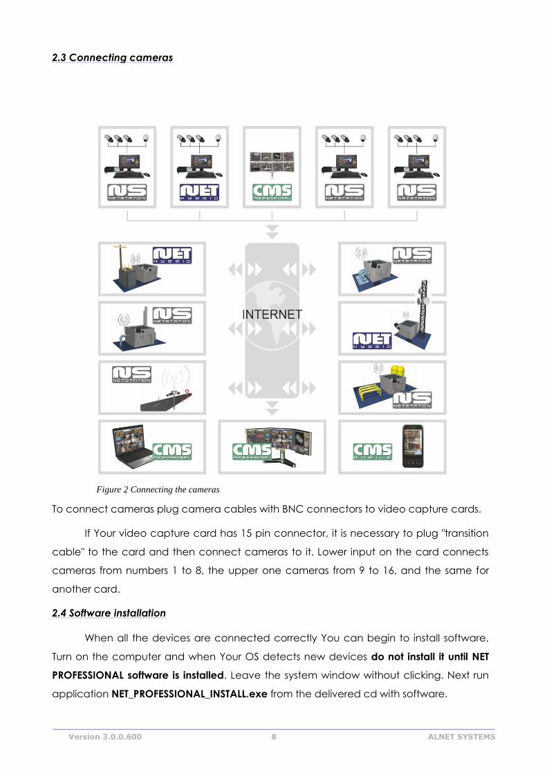
2.3 Connecting cameras
To connect cameras plug camera cables with BNC connectors to video capture cards.
If Your video capture card has 15 pin connector, it is necessary to plug "transition
cable" to the card and then connect cameras to it. Lower input on the card connects
cameras from numbers 1 to 8, the upper one cameras from 9 to 16, and the same for
another card.
2.4 Software installation
When all the devices are connected correctly You can begin to install software.
Turn on the computer and when Your OS detects new devices do not install it until NET
PROFESSIONAL software is installed. Leave the system window without clicking. Next run
application NET_PROFESSIONAL_INSTALL.exe from the delivered cd with software.
Figure 2 Connecting the cameras
Version 3.0.0.600 9 ALNET SYSTEMS
ATTENTION: during installation of NET PROFESSIONAL application, drivers for capture
boards are installed at the same time, which can cause "Windows warning"
displayed regarding lack of Microsoft digital signature in the installed drivers. In this
case press "Continue anyway" in order to install the drivers properly.
After the software is installed You will be asked to restart the computer. At this
stage select "No, I will restart later". Begin video capture cards' drivers installation. If the
Operating System still shows the system window regarding new devices, follow the steps
of the installation panel. If else, You have to install devices manually. Click right mouse
button on My computer icon, select Properties, Hardware bookmark, Device manager
button. Next choose Scan for hardware changes. System will initiate a creator for
installing new devices. Follow the steps. To check if video capture card is installed
properly go to Device manager and "unroll" Sound, video and game controllers menu
(or DVR boards when DSP boards are used). After successful installation of all of the
devices restart Your computer.
3.1 Running the program for the first time
When running the program for the first time it is necessary to define some
parameters, which are essential for proper work. Explanation of this matter is presented
below.
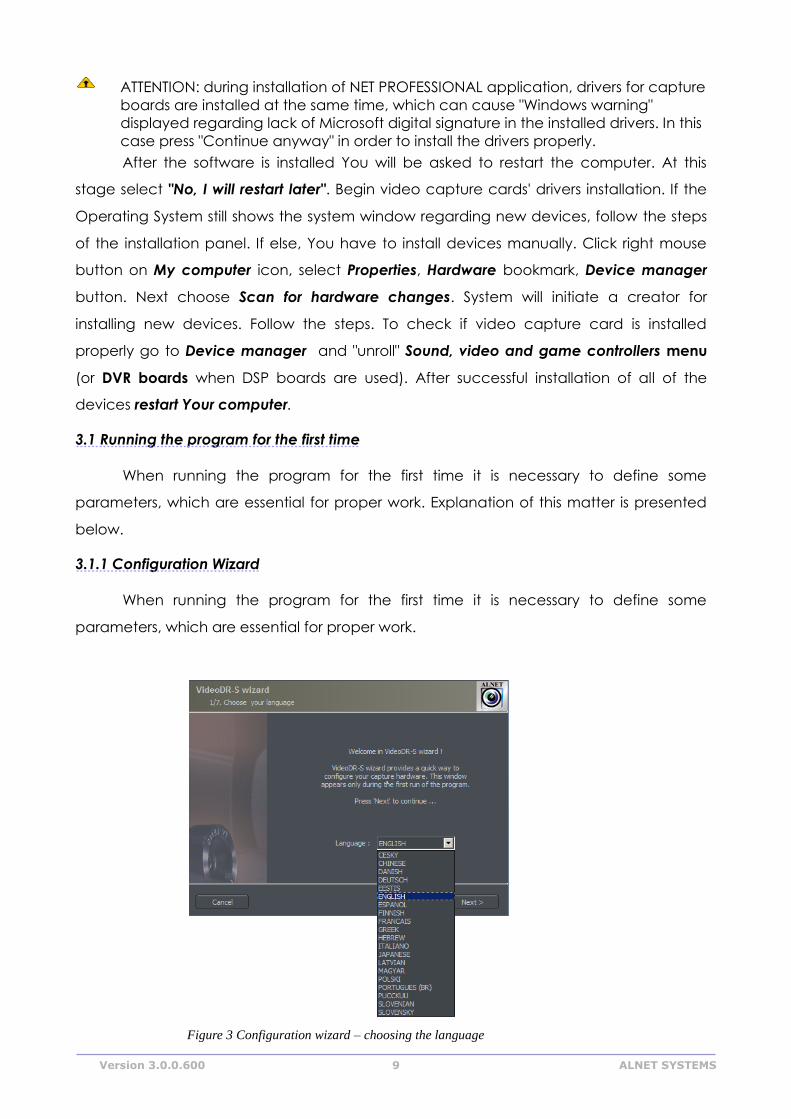
3.1.1 Configuration Wizard
When running the program for the first time it is necessary to define some
parameters, which are essential for proper work.
Figure 3 Configuration wizard – choosing the language
Version 3.0.0.600 10 ALNET SYSTEMS
3.1.1.1 Choosing the language
Pick the language from the list. After this click next button.
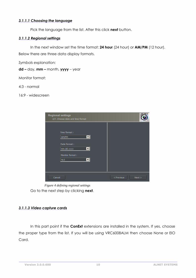
3.1.1.2 Regional settings
In the next window set the time format: 24 hour (24 hour) or AM/PM (12 hour).
Below there are three data display formats.
Symbols explanation:
dd – day, mm – month, yyyy – year
Monitor format:
4:3 - normal
16:9 - widescreen
Go to the next step by clicking next.
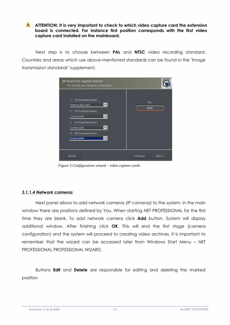
3.1.1.3 Video capture cards
In this part point if the ConExt extensions are installed in the system. If yes, choose
the proper type from the list. If you will be using VRC6008ALM then choose None or EIO
Card.
Figure 4 defining regional settings
Version 3.0.0.600 11 ALNET SYSTEMS
ATTENTION: It is very important to check to which video capture card the extension
board is connected. For instance first position corresponds with the first video
capture card installed on the mainboard.
Next step is to choose between PAL and NTSC video recording standard.
Countries and areas which use above-mentioned standards can be found in the "Image
transmission standards" supplement.
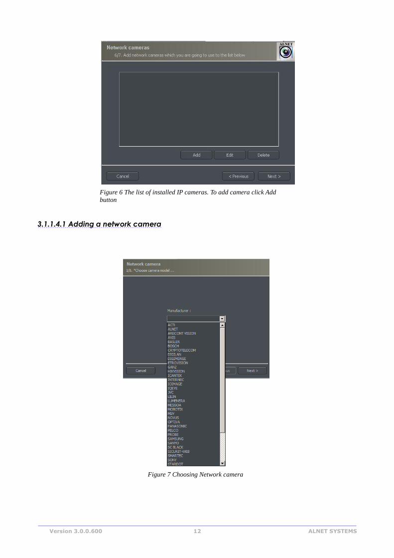
3.1.1.4 Network cameras
Next panel allows to add network cameras (IP cameras) to the system. In the main
window there are positions defined by You. When starting NET PROFESSIONAL for the first
time they are blank. To add network camera click Add button. System will display
additional window. After finishing click OK. This will end the first stage (camera
configuration) and the system will proceed to creating video archives. It is important to
remember that the wizard can be accessed later from Windows Start Menu – NET
PROFESSIONAL PROFESSIONAL WIZARD.
Buttons Edit and Delete are responsible for editing and deleting the marked
position
Figure 5 Configuration wizard – video capture cards
Version 3.0.0.600 12 ALNET SYSTEMS
3.1.1.4.1 Adding a network camera
Figure 7 Choosing Network camera
Figure 6 The list of installed IP cameras. To add camera click Add
button
Version 3.0.0.600 13 ALNET SYSTEMS
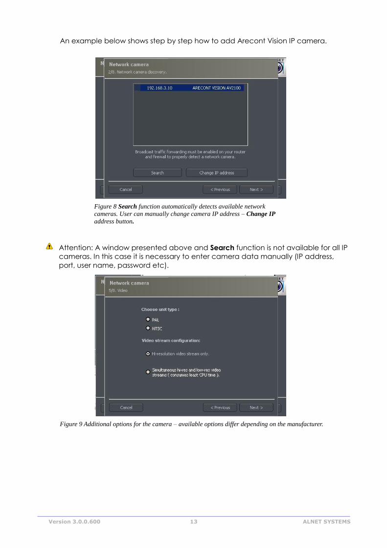
An example below shows step by step how to add Arecont Vision IP camera.
Attention: A window presented above and Search function is not available for all IP
cameras. In this case it is necessary to enter camera data manually (IP address,
port, user name, password etc).
Figure 9 Additional options for the camera – available options differ depending on the manufacturer.
Figure 8 Search function automatically detects available network
cameras. User can manually change camera IP address – Change IP
address button.
Version 3.0.0.600 14 ALNET SYSTEMS
Bookmark Field Description
Network Model Camera model, which we are currently using
Address Address (IP number or domain name)
User Name of the user which has full image streaming
rights
Password Password of the user
HTTP port Number of the port on which camera transmits its
image
Video Camera Type Choose PAL or NTSC format for image transmission
for the camera
Video stream
configuration
Video stream quality choice. When using many of
cameras it is recommended to choose second or
third option. Selecting the second option will cause
the image to be displayed with less fps (only the key
frame will be displayed). Recording will remain at
full fps though. The third option creates two
separate connections: one for recording, one for
displaying the image. The recorded and displayed
image can be diverted. Low display quality saves
the computational power of the processor
Sound
configuration
Enable the sound transmission through the
camera
Table 1: Configuration wizard -network cameras
3.1.1.5 Disk archive
For the proper work of the system it is necessary to configure the disk archive, that
is to point the disk space which will be used for storing the camera image and sound. The
more space will be used, the more archive recordings will be stored.
Disk archive is created in the second stage of configuration wizard – after the
camera configuration is completed.
Figure 10 Creating disk archive
Version 3.0.0.600 15 ALNET SYSTEMS
First window of archive creator offers 3 choose options:
Create a new media archive – create new disk archive
Use existing media archive – configuration of the existing disk
No, don't create media archive now, exit wizard – closing wizard, without creating disk
archive
ATTENTION: In case of using the above option, recording function will not be
available. Later configuration and editing the archive will be available by "Archive
Storage" function in the "Configuration" menu of NET PROFESSIONAL application.
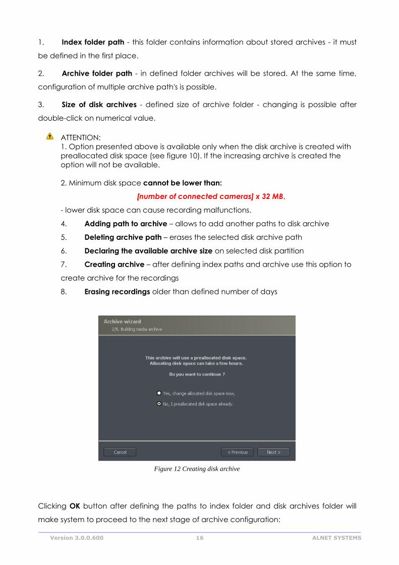
In next step, must be defined, what type of archive will be created. By marking
"Create archive which will use preallocate disk space" will cause creating disk archive,
with size defined by user. Otherwise, archives will be build increasingly, which means that
it will increase it's size during data recording, until it fills whole disk space of selected
partition.
ATTENTION: After filling assigned disk space, NET PROFESSIONAL system continues
recording, successively overwriting the "oldest" archives.
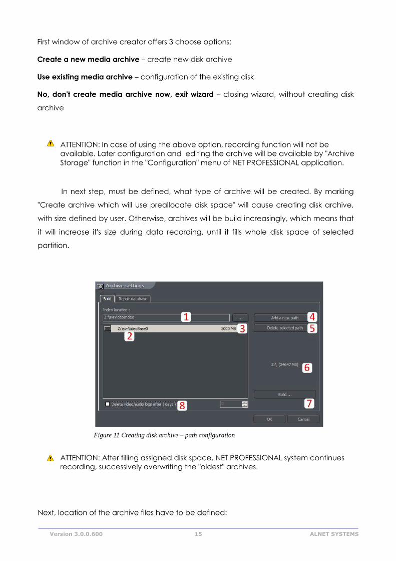
Next, location of the archive files have to be defined:
Figure 11 Creating disk archive – path configuration
Version 3.0.0.600 16 ALNET SYSTEMS
1. Index folder path - this folder contains information about stored archives - it must
be defined in the first place.
2. Archive folder path - in defined folder archives will be stored. At the same time,
configuration of multiple archive path's is possible.
3. Size of disk archives - defined size of archive folder - changing is possible after
double-click on numerical value.
ATTENTION:
1. Option presented above is available only when the disk archive is created with
preallocated disk space (see figure 10). If the increasing archive is created the
option will not be available.
2. Minimum disk space cannot be lower than:
[number of connected cameras] x 32 MB,
- lower disk space can cause recording malfunctions.
4. Adding path to archive – allows to add another paths to disk archive
5. Deleting archive path – erases the selected disk archive path
6. Declaring the available archive size on selected disk partition
7. Creating archive – after defining index paths and archive use this option to
create archive for the recordings
8. Erasing recordings older than defined number of days
Clicking OK button after defining the paths to index folder and disk archives folder will
make system to proceed to the next stage of archive configuration:
Figure 12 Creating disk archive
Version 3.0.0.600 17 ALNET SYSTEMS
1. Yes, change allocated disk space now – this option should be checked
when creating new archive or adding new path for data storage. After
choosing this option system shows the next stage of configuration (see figure
13)
2. No, I preallocated disk space already – this option must be selected when
path of the existing archive is added, or recording path is deleted.
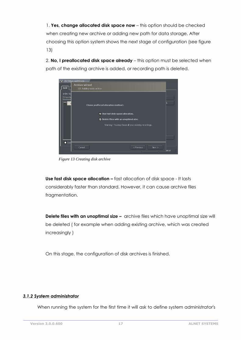
Use fast disk space allocation – fast allocation of disk space - It lasts
considerably faster than standard. However, it can cause archive files
fragmentation.
Delete files with an unoptimal size – archive files which have unoptimal size will
be deleted ( for example when adding existing archive, which was created
increasingly )
On this stage, the configuration of disk archives is finished.
3.1.2 System administrator
When running the system for the first time it will ask to define system administrator's
Figure 13 Creating disk archive
Version 3.0.0.600 18 ALNET SYSTEMS
login and password. Administrator is a person who possesses all the rights to change
system parameters and control system's work. It's very important to remember
administrator's login and password because once given they can not be changed. Also
administrator shouldn't pass these parameters to anyone and keep it confidential.
Next step is to put the product license number. You can find the number printed
on the attached Dongle Key. If this step is skipped some program functions will be
unavailable. Every one hour system will automatically display notification and ask about
license number.
After these actions NET PROFESSIONAL system is ready for use.
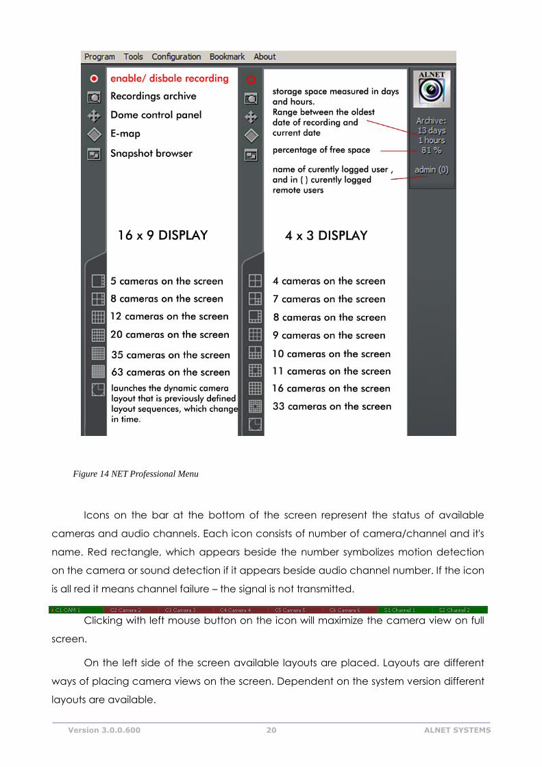
3.2 Main Program Window
Main program window is designed to give immediate access to the most
important program functions. It is possible to simultaneously watch the image from the
cameras, monitor alarm inputs status, switch between displayed cameras and make
snapshots.
Main menu is placed at the top of the screen. It's structure looks as follows:
Program
� Minimize – minimizes the application window
� Log out – logs out the user
� Shutdown system – shuts down the OS
� Restart system – restarts the OS
� Exit – closes the application
Tools
� Browse archives – opens the recordings archives
� Browse photos – opens the snapshots browser
� Register domain – domain registration
� Layout manager – edits layout manager
� Analogue video output – analogue video output configuration
� Export watermark – exports watermark to the file
Version 3.0.0.600 19 ALNET SYSTEMS
� Program console – opens text console
� Program update – checks if any program updates are available
� Sound control – opens system sound mixer
� On-screen keyboard – launches the on-screen keyboard
� Dome panel – opens dome control panel
� E-Map – displays graphic camera layout at particular area
Configuration
� Scheduler – task scheduler tool
� Cameras – camera settings
� Sound – sound channels settings
� Alarm inputs – alarm inputs settings
� Output switches – output switches settings
� Network services – remote access settings
� Archive storage – disk space for archive storage settings
� User accounts – NET PROFESSIONAL user accounts settings
� Dome control – dome control settings
� E-map editor – allows creating graphic layout of the devices at particular area
� Program settings – global program settings
� External tools – Windows tools access
Time and day settings
Mouse properties
Modem options
Network settings
� Save configuration – confirms all the program changes and saves them
Bookmark - adds a bookmark in the archives
About – information about NET PROFESSIONAL server
At the left side of the screen You can find icons, which are shortcuts to the most
important tools.
Version 3.0.0.600 20 ALNET SYSTEMS
Icons on the bar at the bottom of the screen represent the status of available
cameras and audio channels. Each icon consists of number of camera/channel and it's
name. Red rectangle, which appears beside the number symbolizes motion detection
on the camera or sound detection if it appears beside audio channel number. If the icon
is all red it means channel failure – the signal is not transmitted.
Clicking with left mouse button on the icon will maximize the camera view on full
screen.
On the left side of the screen available layouts are placed. Layouts are different
ways of placing camera views on the screen. Dependent on the system version different
layouts are available.
Figure 14 NET Professional Menu
Version 3.0.0.600 21 ALNET SYSTEMS
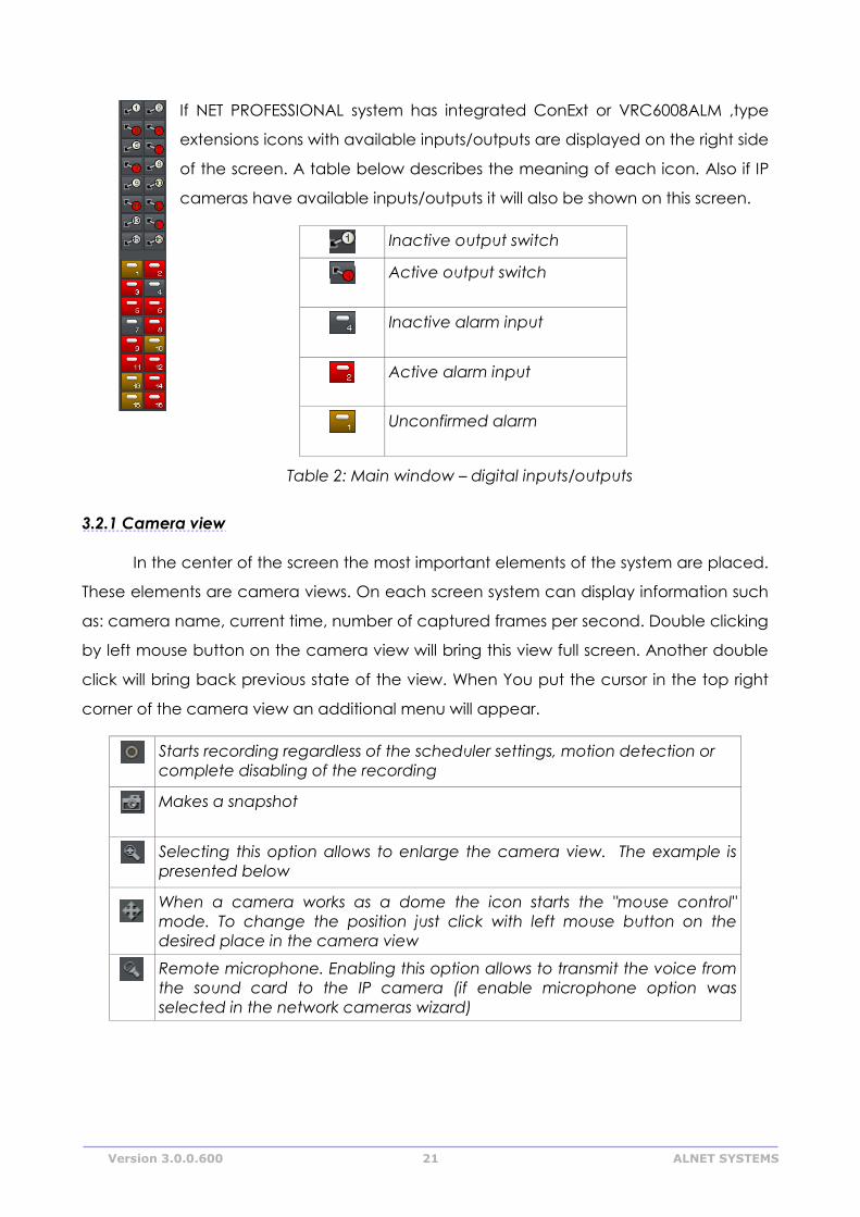
If NET PROFESSIONAL system has integrated ConExt or VRC6008ALM ,type
extensions icons with available inputs/outputs are displayed on the right side
of the screen. A table below describes the meaning of each icon. Also if IP
cameras have available inputs/outputs it will also be shown on this screen.
Inactive output switch
Active output switch
Inactive alarm input
Active alarm input
Unconfirmed alarm
Table 2: Main window – digital inputs/outputs
3.2.1 Camera view
In the center of the screen the most important elements of the system are placed.
These elements are camera views. On each screen system can display information such
as: camera name, current time, number of captured frames per second. Double clicking
by left mouse button on the camera view will bring this view full screen. Another double
click will bring back previous state of the view. When You put the cursor in the top right
corner of the camera view an additional menu will appear.
Starts recording regardless of the scheduler settings, motion detection or
complete disabling of the recording
Makes a snapshot
Selecting this option allows to enlarge the camera view. The example is
presented below
When a camera works as a dome the icon starts the "mouse control"
mode. To change the position just click with left mouse button on the
desired place in the camera view
Remote microphone. Enabling this option allows to transmit the voice from
the sound card to the IP camera (if enable microphone option was
selected in the network cameras wizard)
Version 3.0.0.600 22 ALNET SYSTEMS
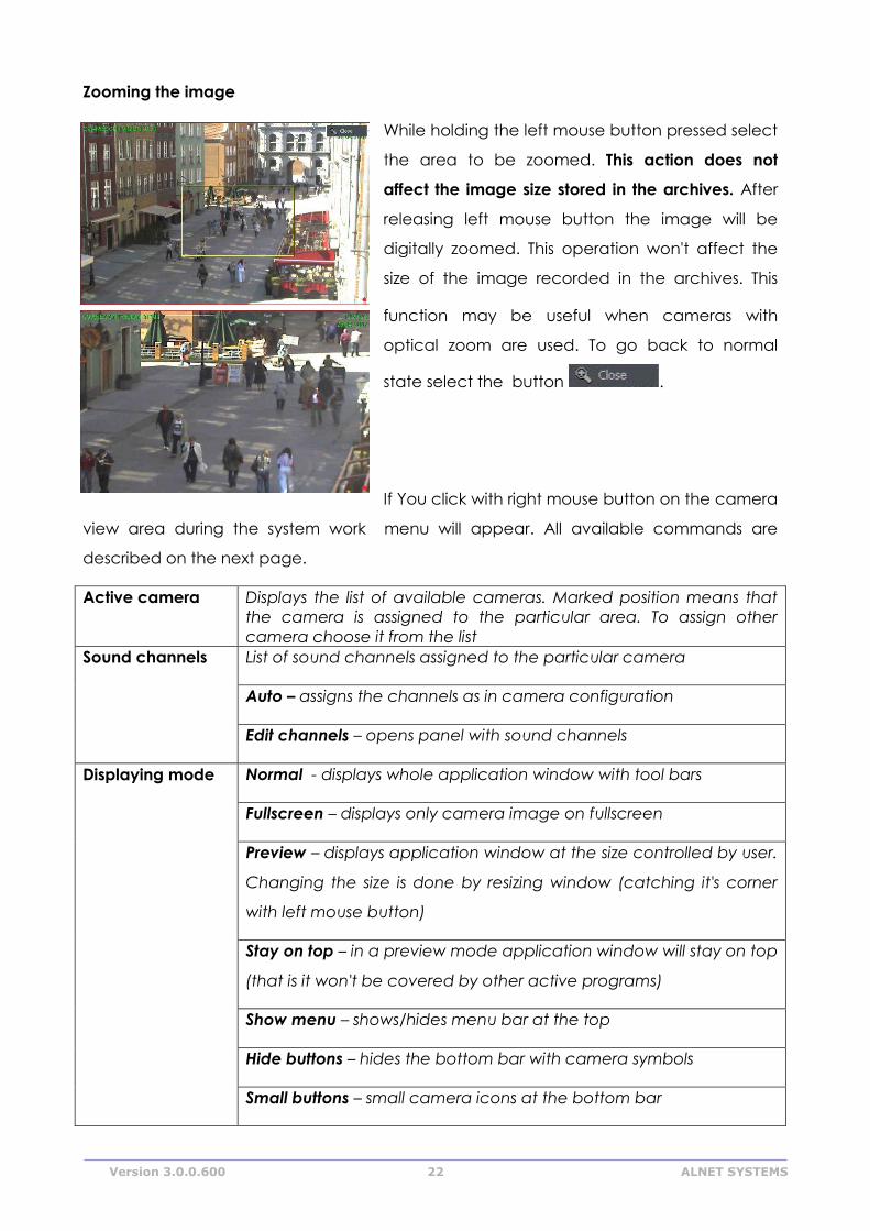
Zooming the image
While holding the left mouse button pressed select
the area to be zoomed. This action does not
affect the image size stored in the archives. After
releasing left mouse button the image will be
digitally zoomed. This operation won't affect the
size of the image recorded in the archives. This
function may be useful when cameras with
optical zoom are used. To go back to normal
state select the button .
If You click with right mouse button on the camera
view area during the system work menu will appear. All available commands are
described on the next page.
Active camera Displays the list of available cameras. Marked position means that
the camera is assigned to the particular area. To assign other
camera choose it from the list
Sound channels List of sound channels assigned to the particular camera
Auto – assigns the channels as in camera configuration
Edit channels – opens panel with sound channels
Displaying mode Normal - displays whole application window with tool bars
Fullscreen – displays only camera image on fullscreen
Preview – displays application window at the size controlled by user.
Changing the size is done by resizing window (catching it's corner
with left mouse button)
Stay on top – in a preview mode application window will stay on top
(that is it won't be covered by other active programs)
Show menu – shows/hides menu bar at the top
Hide buttons – hides the bottom bar with camera symbols
Small buttons – small camera icons at the bottom bar
Version 3.0.0.600 23 ALNET SYSTEMS
Large buttons – large camera icons at the bottom bar
Show tool buttons – shows/hides toolbar at the bottom
Layout Switches to selected camera layout. Enables dynamic mode.
Dynamic – if Camera pop-up after alarm option was selected in
camera configuration, it is possible to temporarily disable/enable
this option by marking it
Add bookmark Adds a bookmark to archive recording
Snapshot Makes screenshot (photo)
Most of the options mentioned above refer to single camera. It is very important to
choose the proper camera (by clicking with left mouse button on it's display area)
before selecting any option. Selected camera has a red border.
3.3 Scheduler
NET PROFESSIONAL system allows to configure schedule for: cameras, sound
recording, alarm inputs and system alerts. It allows to diverse the work of the system, it's
reactions to alarms on working days of the week, weekends or in night hours. It is a very
strong and versatile tool, which can help You to adjust the system to all of Your needs.
Activation of the scheduler events can be achieved either by defining the time range or
activation of the alarm input.
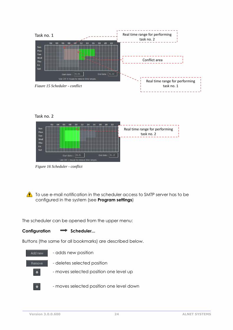
During the work with scheduler it is necessary to pay attention to the order of the
scheduled tasks. The higher the task is on the list the lower is it's priority. For example if the
first task on the list activates continuous image recording for all cameras and the second
task disables the recording a the same time – then the system will disable recording as
the second task has higher priority. In case on task conflict (overlapping) proper marks
will be shown on the time axis. Suppose two positions were defined, which "time borders"
overlap each other. Time axis will be displayed as follows:
Version 3.0.0.600 24 ALNET SYSTEMS
To use e-mail notification in the scheduler access to SMTP server has to be
configured in the system (see Program settings)
The scheduler can be opened from the upper menu:
Configuration Scheduler...
Buttons (the same for all bookmarks) are described below.
- adds new position
- deletes selected position
- moves selected position one level up
- moves selected position one level down
Task no. 1
Figure 15 Scheduler - conflict
Figure 15:
Task no. 2
Figure 16 Scheduler - conflict
Figure 16:
Real time range for performing task no. 2
Real time range for performing task no. 1
Real time range for performing task no. 2
Conflict area
Version 3.0.0.600 25 ALNET SYSTEMS
3.3.1 Cameras schedule
To add a new task select Add new. A new position will appear on the list – select it.
Beside the positions list Activation condition panel is placed. It characterizes the task to
be controlled by the time or alarm input activation.
- launching the task in due time
- launching the task by alarm input activation
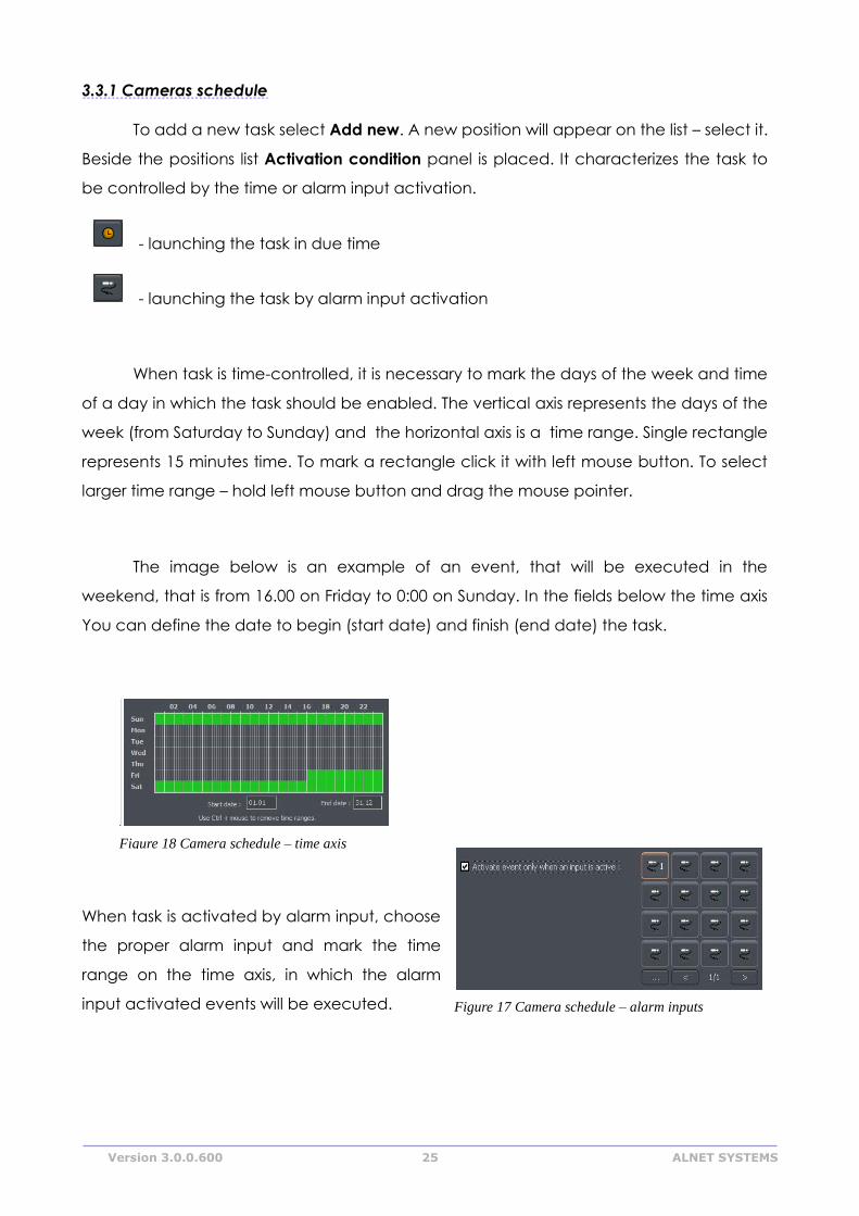
When task is time-controlled, it is necessary to mark the days of the week and time
of a day in which the task should be enabled. The vertical axis represents the days of the
week (from Saturday to Sunday) and the horizontal axis is a time range. Single rectangle
represents 15 minutes time. To mark a rectangle click it with left mouse button. To select
larger time range – hold left mouse button and drag the mouse pointer.
The image below is an example of an event, that will be executed in the
weekend, that is from 16.00 on Friday to 0:00 on Sunday. In the fields below the time axis
You can define the date to begin (start date) and finish (end date) the task.
When task is activated by alarm input, choose
the proper alarm input and mark the time
range on the time axis, in which the alarm
input activated events will be executed.
Figure 18 Camera schedule – time axis
Figure 17:
Figure 17 Camera schedule – alarm inputs
Figure 18:
Version 3.0.0.600 26 ALNET SYSTEMS
Description of other options:
Name Description
Task name Name of the task, which will appear on the task list
Cameras To which cameras the task will apply
Recording Image recording options
Options Recording time after motion detection – if motion option was
selected it determines how much time (in seconds) after the motion
detection the recording will last; motion time before motion alarm –
determines how long (in seconds) must the motion last, to activate
the alarm event.
After motion
alarm
The way that systems informs about alarm event. There are three
possibilities:
Send email - sends email notification on previously given
address
Set outputs - activates selected output switches
Connect to client – activates the connection with selected remote
client, used for example in monitoring headquarters
3.3.2 Sounds schedule
"Schedule sounds" bookmark allows to "plan" system reactions to sound events.
Activation conditions are the same as in camera schedule. The difference is that You
choose sound channels. Additional reaction to alarm event is starting the image
recording from selected cameras. Recording time is set in Options field.
Night can represent an example situation. Cameras have limited possibilities to
detect motion but sensitive microphone can detect noise, start the alarm and enable
output switch, which will turn on the light and this will make image recording possible.
3.3.3 Alarm inputs schedule
This module is used for programming the behavior of the alarm inputs and their
reactions on alarm. Programming the event looks the same as in camera and sound
schedule. Additionally, after the alarm detection system can add bookmark to archives
and enable the output switch (for example with connected siren). In the Options panel
Activation time before alarm can be set (a time needed for the system to recognize the
input activation as an alarm).
Version 3.0.0.600 27 ALNET SYSTEMS
3.3.4 System alerts
System alerts are responsible for notifications about changes in system work. You
can set notifications for example about application shutdown, remote user login or
camera signal lost. The list of available alerts is presented below:
Program start up
Program shut down
Recording on
Recording off
Camera connected
Camera disconnected
Remote user login
Remote user login failed
Remote user logout
Video signal restored
Video signal lost
User is sleeping (no user reaction for
system popups)
Defining new task process is the same as in previous modules.
3.3.5 Scheduler – Address book
Address book manages the contacts to which the alarm notifications are sent or
to connect with remote clients.
3.3.5.1 E-mail address
Figure 19 Address book – e-mail addresses
Version 3.0.0.600 28 ALNET SYSTEMS
Address book panel consists of two bookmarks: Choose address and Address
book. First bookmark displays the list of available contacts, the second one allows to
add, remove and edit contacts. To add new contact choose "Add new" button in the
Address book bookmark. After filling all of the empty fields click "Ok" button or "Add new"
button if You want to add new address.
Field Description
Description Name which will appear in the contact list
E-mail address E-mail address to which notification will be sent
Subject Subject of an e-mail notification message
Do not send more often than
(s.)
The minimum time gap between two messages
Attach screenshots Allows to attach screenshots from selected cameras to
e-mail notification message
Get screenshots after (s.) Time gap between alarm activation and camera
image snapshot
After filling all the fields select Ok to finish or Add new (to add new contact).
Figure 20 Address book – e-mail addresses
Version 3.0.0.600 29 ALNET SYSTEMS
3.3.5.2 Client addresses
In this place You can add addresses of the remote client applications to which
server application will send notifications. The way server sends notifications to client
applications is presented on a diagram below.
To add new contact it is necessary to fill all the blank fields:
Field Description
Description Name which will appear in the contact list
Client address and port Address and port of the remote client
Client password Password selected for sending notifications
Server user Server user login
Server password Server user password
Dial-up connection If dial-up connection is configured it is possible to "call"
client application
After filling all the fields select Ok to finish or Add new (to add new contact).
3.3 Camera configuration
NET PROFESSIONAL system allows to configure many camera parameters. Quality
of displayed image, compression settings, drawing a mask of areas, in which motion
detection will be omitted. Configuration panel can be reached from the top menu bar:
Configuration Cameras
or by Ctrl+C shortcut combination.
Figure 21 Schema for sending notifications to the client
Version 3.0.0.600 30 ALNET SYSTEMS
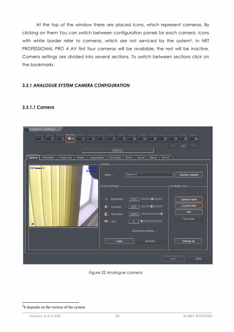
At the top of the window there are placed icons, which represent cameras. By
clicking on them You can switch between configuration panels for each camera. Icons
with white border refer to cameras, which are not serviced by the system3. In NET
PROFESSIONAL PRO 4 AV first four cameras will be available, the rest will be inactive.
Camera settings are divided into several sections. To switch between sections click on
the bookmarks.
3.3.1 ANALOGUE SYSTEM CAMERA CONFIGURATION
3.3.1.1 Camera
Figure 22 Analogue camera
3It depends on the version of the system
Version 3.0.0.600 31 ALNET SYSTEMS
Panel Field Description
Camera Name Name describing camera
Connect camera Enables the video stream capture
Picture settings Brightness, Contrast,
Saturation, Hue,
Sharpness
Parameters characterizing the image. To
change parameter move the slider
Color Enables the color mode (if color camera)
Default Restores the default settings
On-display text Camera name Display camera name on the screen
Current time Display current time on the screen
Fps Display the number of captured fps on the
screen
Text color Changes the text color
Change all Changes the settings for all connected
cameras
Advanced
settings
( applies only to
small camera
view )
Sharpen Sharpen the image on small view
Software
deinterlace
During the analogue – digital signal
conversion, semi-images are not created in
the same time but gathered one after
another. After they are put together there is a
visible effect of shift between even and odd
lines. It is especially visible in fast-changing
scenes. Selecting this option will remove the
effect.
Decode scale
1:1
1:2
1:4
1:8
Decode framerate Unlimited – the same amount of frames as on
live view.
Medium – half of the frames on live view
Low – 1/4 quarter
Lowest – 1/8 of the frames on live view
On-display text Camera name Display camera name on the screen
Current time Display current time on the screen
Fps Display the number of captured fps on the
screen
Text color Changes the text color
Change all Changes the settings for all connected
cameras
Version 3.0.0.600 32 ALNET SYSTEMS
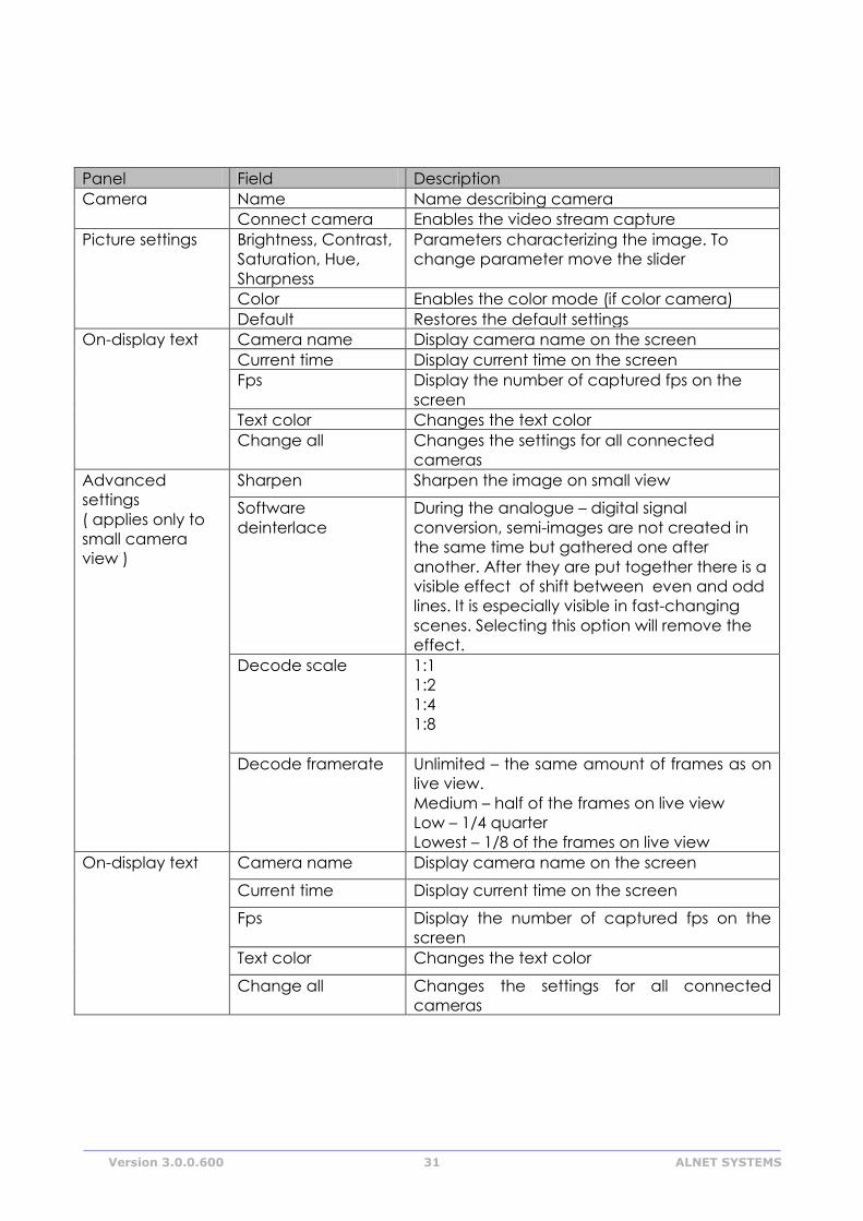
3.3.1.2 Resolution
Figure 23 Resolution
Panel Field Description
Device Software
deinterlace
During the analogue – digital signal conversion, semi-
images are not created in the same time but
gathered one after another. After they are put
together there is a visible effect of shift between
even and odd lines. It is especially visible in fast-
changing scenes. Selecting this option will remove
the effect.
Resolution
CIF Display the camera at 352 x 288
2 CIF Display the camera at 704 x 288
4 CIF Display the camera at 704 x 576
D1 Display the camera at 720 x 576
Apply to all Applies the changes to all connected cameras
Version 3.0.0.600 33 ALNET SYSTEMS
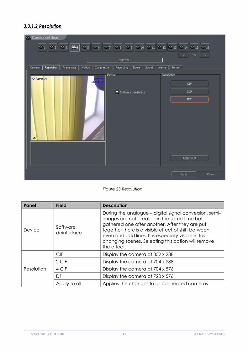
3.3.1.3 Compression
Figure 24 Compression
3.3.2 IP CAMERA CONFIGURATION
Depending on the IP camera, the tags can be different. Most of the new IP
devices need to be set on www and the stream
Version 3.0.0.600 34 ALNET SYSTEMS
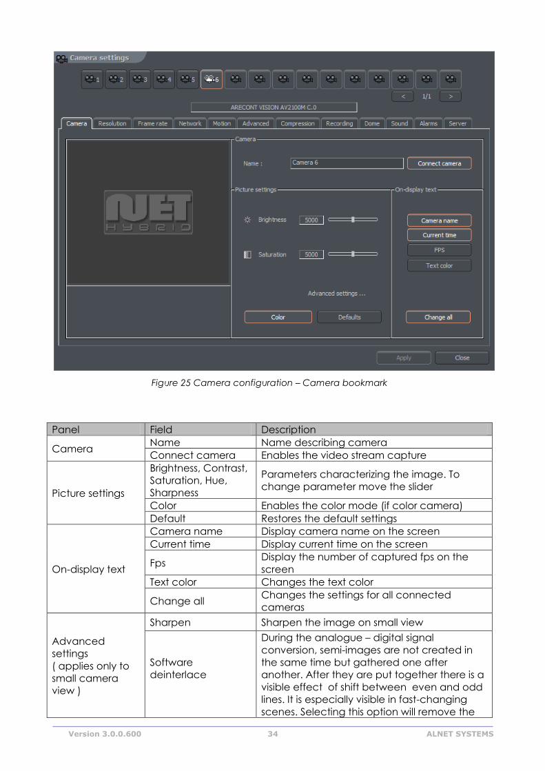
Figure 25 Camera configuration – Camera bookmark
Panel Field Description
Camera Name Name describing camera
Connect camera Enables the video stream capture
Picture settings
Brightness, Contrast,
Saturation, Hue,
Sharpness
Parameters characterizing the image. To
change parameter move the slider
Color Enables the color mode (if color camera)
Default Restores the default settings
On-display text
Camera name Display camera name on the screen
Current time Display current time on the screen
Fps Display the number of captured fps on the
screen
Text color Changes the text color
Change all Changes the settings for all connected
cameras
Advanced
settings
( applies only to
small camera
view )
Sharpen Sharpen the image on small view
Software
deinterlace
During the analogue – digital signal
conversion, semi-images are not created in
the same time but gathered one after
another. After they are put together there is a
visible effect of shift between even and odd
lines. It is especially visible in fast-changing
scenes. Selecting this option will remove the
Version 3.0.0.600 35 ALNET SYSTEMS
effect.
Decode scale
1:1
1:2
1:4
1:8
Decode framerate
Unlimited – the same amount of frames as on
live view.
Medium – half of the frames on live view
Low – 1/4 quarter
Lowest – 1/8 of the frames on live view
On-display text
Camera name Display camera name on the screen
Current time Display current time on the screen
Fps Display the number of captured fps on the
screen
Text color Changes the text color
Change all Changes the settings for all connected
cameras
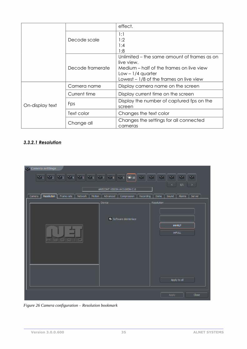
3.3.2.1 Resolution
Figure 26 Camera configuration – Resolution bookmark
Version 3.0.0.600 36 ALNET SYSTEMS
Panel Field Description
Device Software
deinterlace
During the analogue – digital signal conversion, semi-
images are not created in the same time but
gathered one after another. After they are put
together there is a visible effect of shift between
even and odd lines. It is especially visible in fast-
changing scenes. Selecting this option will remove
the effect.
Resolution Resolution of captured image. The higher resolution the better image
quality and more space is required for archive recordings storage. Some
cameras, instead of specific resolution can provide only ImHalf and ImFull
– it means that the image is in half and full available resolution for
particular camera
Apply to all Applies the changes to all connected cameras
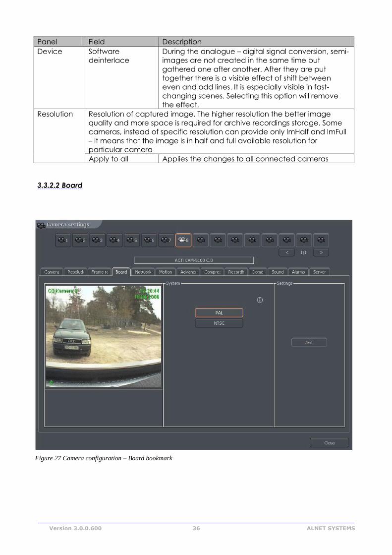
3.3.2.2 Board
Figure 27 Camera configuration – Board bookmark
Version 3.0.0.600 37 ALNET SYSTEMS
Panel Description
System Camera image transmission standard PAL/NTSC
Skip frames Option allows to set the number of frames to skip. Increasing the
parameter lowers the number of displayed and recorded frames. It
lowers both the CPU usage and storage place needed on the hard
disk
Settings AGC – Automatic Gain Control. Auto regulation of source amplifier
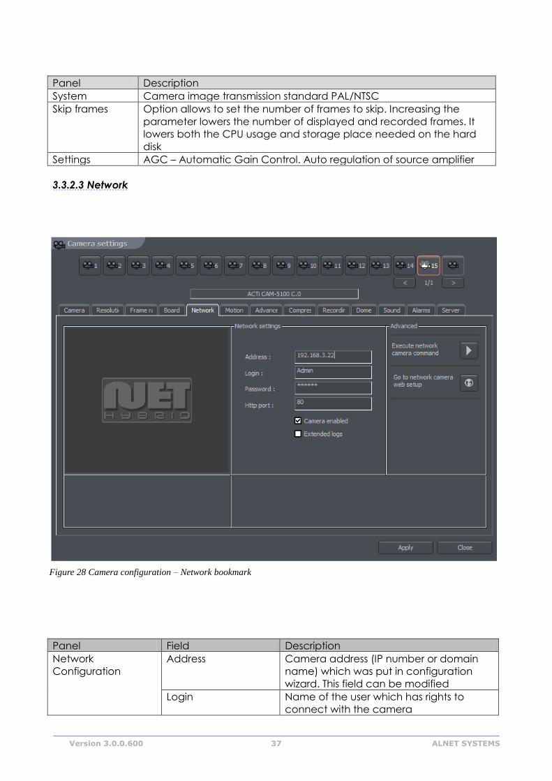
3.3.2.3 Network
Panel Field Description
Network
Configuration
Address Camera address (IP number or domain
name) which was put in configuration
wizard. This field can be modified
Login Name of the user which has rights to
connect with the camera
Figure 28 Camera configuration – Network bookmark
Version 3.0.0.600 38 ALNET SYSTEMS
Password User password
Http port Port through which the camera sends an
image
Camera enabled Deselecting this field causes the system
not to service the camera (including
digital inputs/outputs, sound)
Extended log System administrator help in solving
problems with network cameras. After
marking this option every command sent
to camera and every camera reply is
saved to logs
Advanced Go to configuration
on the website
Opens internet browser on the camera
configuration web page
Execute network
camera command
Loads the camera configuration
(brightness, contrast, resolution etc.) from
the camera to NET Professional. If the
camera configuration is changed from
the www browser level it is possible to
download these new settings to VDRS, set
factory defaults or restart the camera.
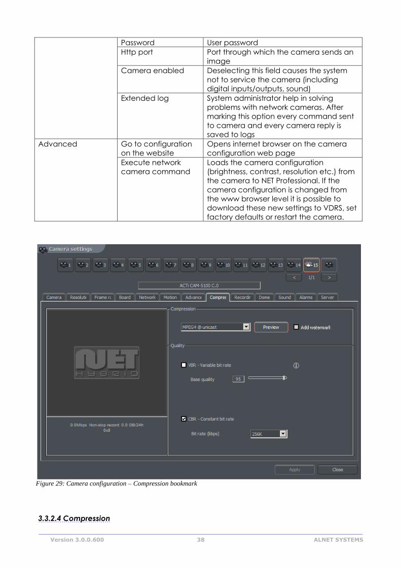
3.3.2.4 Compression
Figure 29: Camera configuration – Compression bookmark
Version 3.0.0.600 39 ALNET SYSTEMS
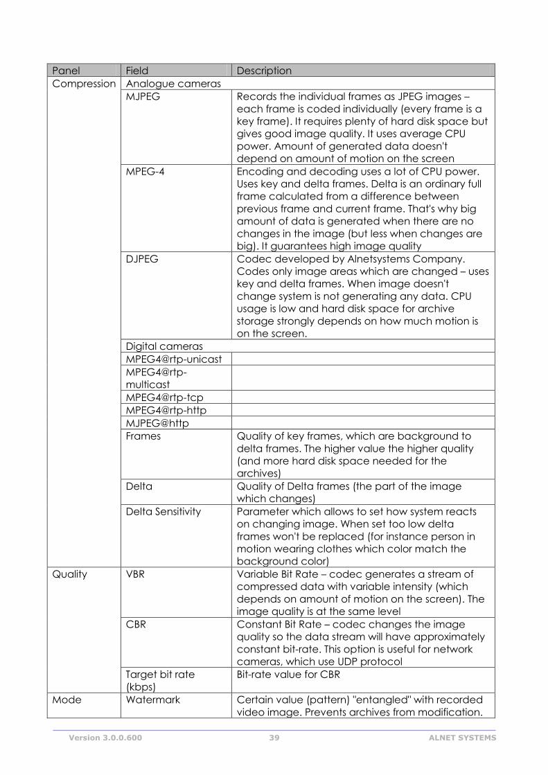
Panel Field Description
Compression Analogue cameras
MJPEG Records the individual frames as JPEG images –
each frame is coded individually (every frame is a
key frame). It requires plenty of hard disk space but
gives good image quality. It uses average CPU
power. Amount of generated data doesn't
depend on amount of motion on the screen
MPEG-4 Encoding and decoding uses a lot of CPU power.
Uses key and delta frames. Delta is an ordinary full
frame calculated from a difference between
previous frame and current frame. That's why big
amount of data is generated when there are no
changes in the image (but less when changes are
big). It guarantees high image quality
DJPEG Codec developed by Alnetsystems Company.
Codes only image areas which are changed – uses
key and delta frames. When image doesn't
change system is not generating any data. CPU
usage is low and hard disk space for archive
storage strongly depends on how much motion is
on the screen.
Digital cameras
MPEG4@rtp-unicast
MPEG4@rtp-
multicast
MPEG4@rtp-tcp
MPEG4@rtp-http
MJPEG@http
Frames Quality of key frames, which are background to
delta frames. The higher value the higher quality
(and more hard disk space needed for the
archives)
Delta Quality of Delta frames (the part of the image
which changes)
Delta Sensitivity Parameter which allows to set how system reacts
on changing image. When set too low delta
frames won't be replaced (for instance person in
motion wearing clothes which color match the
background color)
Quality VBR Variable Bit Rate – codec generates a stream of
compressed data with variable intensity (which
depends on amount of motion on the screen). The
image quality is at the same level
CBR Constant Bit Rate – codec changes the image
quality so the data stream will have approximately
constant bit-rate. This option is useful for network
cameras, which use UDP protocol
Target bit rate
(kbps)
Bit-rate value for CBR
Mode Watermark Certain value (pattern) "entangled" with recorded
video image. Prevents archives from modification.
Version 3.0.0.600 40 ALNET SYSTEMS
Watermark is not visible on the screen, but it is
possible to check (by VDR-A application) if it exists
in the archives or not. Watermark is unique for each
VDR-S system. Every modification of the recorded
video destroys the watermark and during the
watermark check the system will pop up error. To
make checking watermark function possible it is
necessary to export it first:
Tools -> Export watermark
Preview
decoding
Preview framerate Only for IP cameras – frames per second for the
stream sent to:
- display
- motion detection
- remote clients with free bandwidth
Preview scale Applies only for IP cameras with MJPEG codec
Preview Allows to calculate approximate size of recorded data and video stream
for specified image quality settings
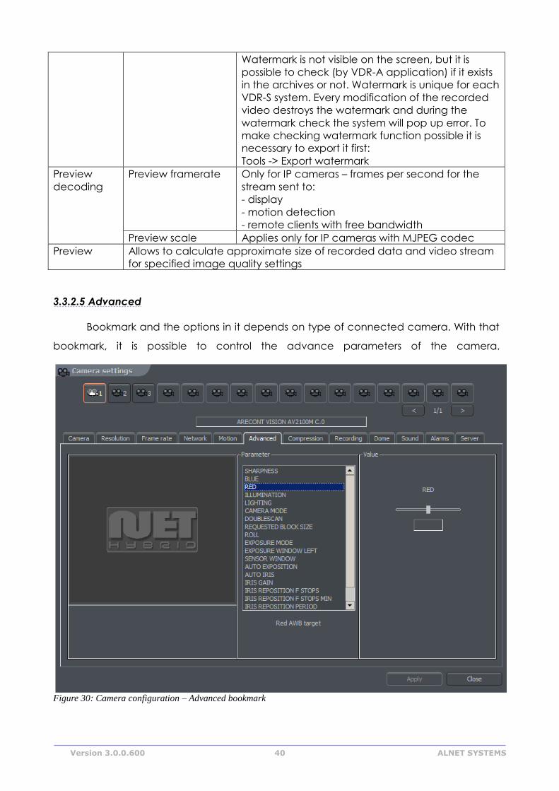
3.3.2.5 Advanced
Bookmark and the options in it depends on type of connected camera. With that
bookmark, it is possible to control the advance parameters of the camera.
Figure 30: Camera configuration – Advanced bookmark
Version 3.0.0.600 41 ALNET SYSTEMS
3.3.3 Common configuration settings
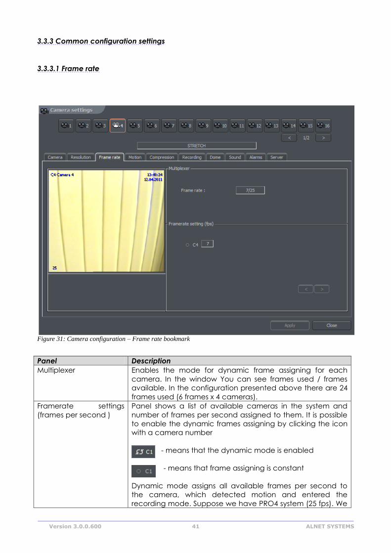
3.3.3.1 Frame rate
Panel Description
Multiplexer Enables the mode for dynamic frame assigning for each
camera. In the window You can see frames used / frames
available. In the configuration presented above there are 24
frames used (6 frames x 4 cameras).
Framerate settings
(frames per second )
Panel shows a list of available cameras in the system and
number of frames per second assigned to them. It is possible
to enable the dynamic frames assigning by clicking the icon
with a camera number
- means that the dynamic mode is enabled
- means that frame assigning is constant
Dynamic mode assigns all available frames per second to
the camera, which detected motion and entered the
recording mode. Suppose we have PRO4 system (25 fps). We
Figure 31: Camera configuration – Frame rate bookmark
Version 3.0.0.600 42 ALNET SYSTEMS
set the constant number of frames per second for each
camera on 4. 9 frames per second stay unused ( 25 fps - [4
cam. X 4 fps = 16 fps] = 9 fps). These 9 unused frames can be
assigned to any camera by enabling it's dynamic mode. If
the dynamic mode is enabled for two or more cameras, the
system assigns unused frames between the cameras evenly.
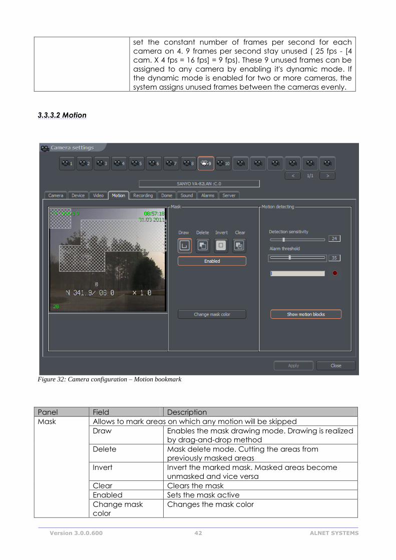
3.3.3.2 Motion
Panel Field Description
Mask Allows to mark areas on which any motion will be skipped
Draw Enables the mask drawing mode. Drawing is realized
by drag-and-drop method
Delete Mask delete mode. Cutting the areas from
previously masked areas
Invert Invert the marked mask. Masked areas become
unmasked and vice versa
Clear Clears the mask
Enabled Sets the mask active
Change mask
color
Changes the mask color
Figure 32: Camera configuration – Motion bookmark
Version 3.0.0.600 43 ALNET SYSTEMS
Motion
detection
Detection
sensitivity
The system detects motion as changes in the image.
Application analyses the data and classifies them as
a motion detection or not. The slider allows to set the
sensitivity level for these changes
Alarm threshold Level, from which the system reacts to changes in
the image. It is recommended to set the threshold
when the image is in stillness. It will help to eliminate
recording of the insignificant motion, such as leaves
motion on the wind and camera noise. Below the
slider there is a field which shows current alarm level
Show motion
blocks
Enables plotting the motion blocks on the image, in
which the system detects motion. This option is useful
while modifying the motion detection settings
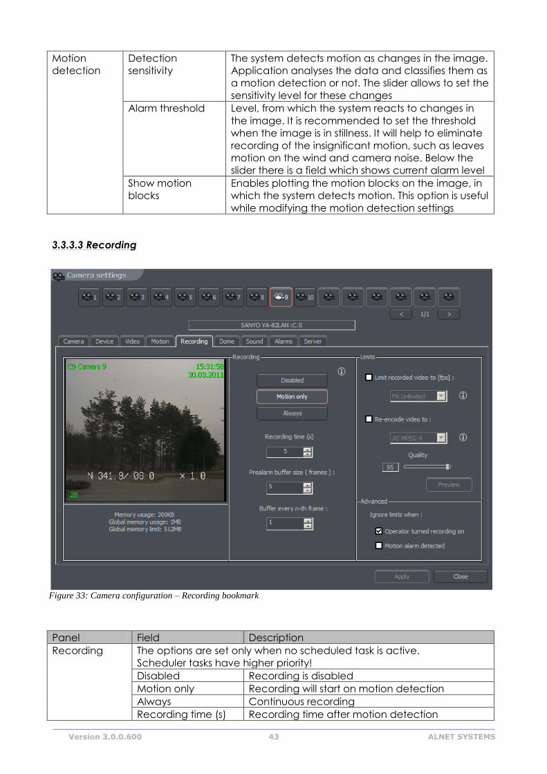
3.3.3.3 Recording
Panel Field Description
Recording The options are set only when no scheduled task is active.
Scheduler tasks have higher priority!
Disabled Recording is disabled
Motion only Recording will start on motion detection
Always Continuous recording
Recording time (s) Recording time after motion detection
Figure 33: Camera configuration – Recording bookmark
Version 3.0.0.600 44 ALNET SYSTEMS
Prealarm
Prealarm is function of early reaction for alarm. It enables to recreate
recordings from moments before activating alarm. When the function is
enabled, the application is buffering image, and when movement is
detected (and recording is set on) the frames recorded before alarm
remain to user's disposal. The length of buffered image in case of
network cameras depends on memory size reserved for prealarm. For
analogue cameras two parameters are being set up:
Prealarm buffer size (frame) – quantity of buffered frames
Buffer every n-th frame – ratio of buffered frames to non-buffered
Example:
Camera in the system records 5 fr/sec. If define 5 buffered frames and
quantity of buffered frames for one the result will be 1 second of
buffered recording. The formula for calculating length of the buffer is
presented below.
For the example above:
(5 * 1) / 5 = 1 sec
Advanced Limit recorded
video to [fps]
Function limits fps in the recorded video – this
function can be used to save space on a hard drive
Re-encode
video to:
Function allows to re-compress video stream to
other format independently on the input video
stream which is sent by camera or video capture
card
Quality Setting for quality of re-compressed video
Ignore limits
when:
Option ignores limits mentioned above in two
defined cases:
- Recording is triggered manually by the operator
- Motion detection alarm has occurred
Buffer =Prealarm buffer size(frame) * Buffer every n-th frame
Number of recorded frames
Version 3.0.0.600 45 ALNET SYSTEMS
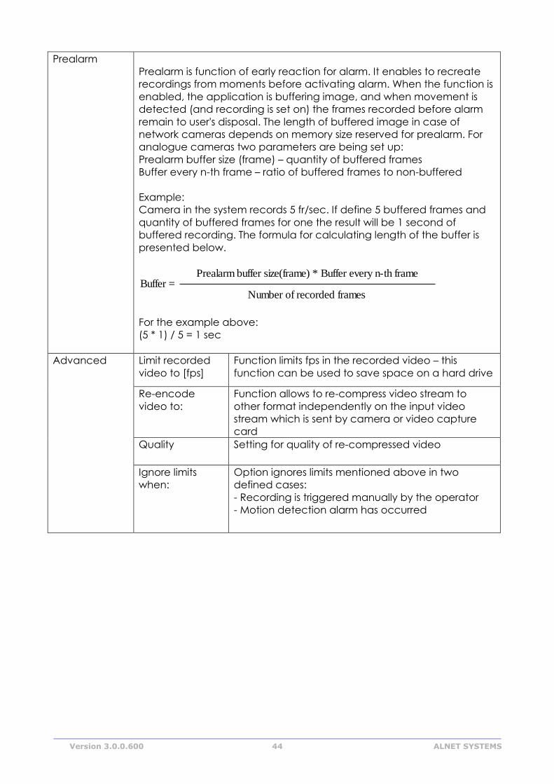
3.3.3.4 Dome
Panel Field Description
Dome settings Address Address, which was set on hardware, for
example by jumpers on the dome. It is
necessary to pay attention which address is
assigned to particular setting (dome manual).
Sometimes position '1' means address number
'0', and not '1' as one may suppose (for
instance Pelco D protocol)
Port COM port, to which the dome control is
plugged. If the protocol is set in Dome control
panel it's name will be visible
Protocol Protocol for dome control
Dome enabled Enables the dome control in the system
Preset
Sequence
Automatic dome control. Switching between previously set positions.
This option works only with domes, which support saving and recalling
presets. It is possible to set up to 128 positions. For proper work the
dome protocol has to have two command included: 'Save preset' and
'Recall preset'.
Activate after [sec] The time gap between last manual command
(for example from the keyboard) and Preset
activation
Figure 34: Camera configuration – Dome bookmark
Version 3.0.0.600 46 ALNET SYSTEMS
Preset dwell time
[sec.]
The time the dome stops on a preset for
Activate on program
start
Activates sequence on Net Professional
system start
Preset
Sequence
On the left side there is a list, from which the set of presets can be
chosen. One set is 16 positions. To save the dome position under
desired preset click on its number. To add preset to AutoPan
sequence mark it's checkbox.
ATTENTION! To activate AutoPan it is necessary to mark option in the
dome control panel. You can call dome control panel using the Ctrl+D
keyboard shortcut or from the current bookmark
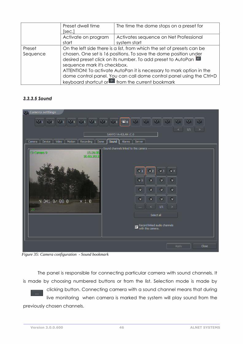
3.3.3.5 Sound
The panel is responsible for connecting particular camera with sound channels. It
is made by choosing numbered buttons or from the list. Selection mode is made by
clicking button. Connecting camera with a sound channel means that during
live monitoring when camera is marked the system will play sound from the
previously chosen channels.
Figure 35: Camera configuration - Sound bookmark
Version 3.0.0.600 47 ALNET SYSTEMS
3.3.3.6 Alarms
Panel Field Description
Actions after motion
alarm
Play sound Activates sound alarm. System will play sound
defined below in sound file path.
Show
camera
Marking this option will cause the camera
image to be shown in full screen. When
application is minimized after the motion
detection the program window will be
maximized and will show the camera, on which
the motion was detected. The the program
window will minimize. During the normal work
the system will show the camera on full screen
and will back to the previous layout
Show text Shows pop up message from the VDRS system
tray icon
Motion time
before
motion
alarm
Determines the time which should last before
the motion is detected as an alarm
Sound file
path
Figure 36: Camera configuration - Alarms bookmark
Version 3.0.0.600 48 ALNET SYSTEMS
Actions after signal loss Play sound Activates sound alarm. System will play sound
defined in settings panel
Show
camera
Marking this option will cause the camera
image to be shown in full screen. When
application is minimized after the motion
detection the program window will be
maximized and will show the camera, on which
the motion was detected. The the program
window will minimize. During the normal work
the system will show the camera on full screen
and will back to the previous layout
Show text Shows pop up message from the VDRS system
tray icon
Motion time
before
motion
alarm
Determines the time which should last before
the motion is detected as an alarm
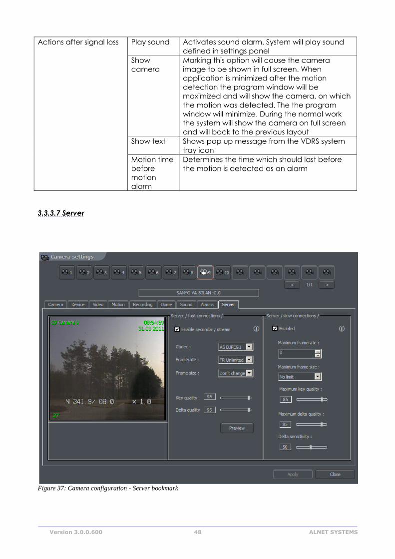
3.3.3.7 Server
Figure 37: Camera configuration - Server bookmark
Version 3.0.0.600 49 ALNET SYSTEMS
Server bookmark allows activation and configuration of additional video streams for
remote clients for fast and slow connections.
Panel Field Description
Server /fast
connections/
Codec Choice of codec for video stream
transmission
Framerate Amount of frames per second in transferred
image
FR unlimited
Frame size Frame size of the
image
Key quality See paragraph 3.3.7 Compression
Delta quality See paragraph 3.3.7 Compression
Server /slow
connections/
Maximum framerate Maximum frames per second for video stream
transmission
Maximum frame size Maximum frame size
Maximum key quality See paragraph 3.3.7 Compression
Maximum delta
quality
See paragraph 3.3.7 Compression
Delta sensitivity See paragraph 3.3.7 Compression
Preview See paragraph 3.3.7 Compression
3.4 Sound configuration
NET PROFESSIONAL System allows sound capture by extension cards or sound
card. It is possible to capture up to 32 channels. You can set system to enable alarm
inputs on sound, control the dome. For each channel the panel below allows to
configure recording quality, volume and way the system reacts on sound detection.
Version 3.0.0.600 50 ALNET SYSTEMS
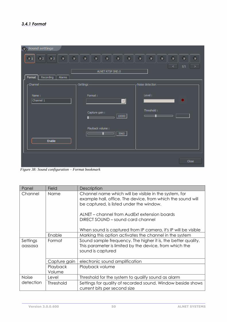
3.4.1 Format
Panel Field Description
Channel Name Channel name which will be visible in the system, for
example hall, office. The device, from which the sound will
be captured, is listed under the window.
ALNET – channel from AudExt extension boards
DIRECT SOUND – sound card channel
When sound is captured from IP camera, it's IP will be visible
Enable Marking this option activates the channel in the system
Settings
aassasa
Format Sound sample frequency. The higher it is, the better quality.
This parameter is limited by the device, from which the
sound is captured
Capture gain electronic sound amplification
Playback
Volume
Playback volume
Noise
detection
Level Threshold for the system to qualify sound as alarm
Threshold Settings for quality of recorded sound. Window beside shows
current bits per second size
Figure 38: Sound configuration – Format bookmark
Version 3.0.0.600 51 ALNET SYSTEMS
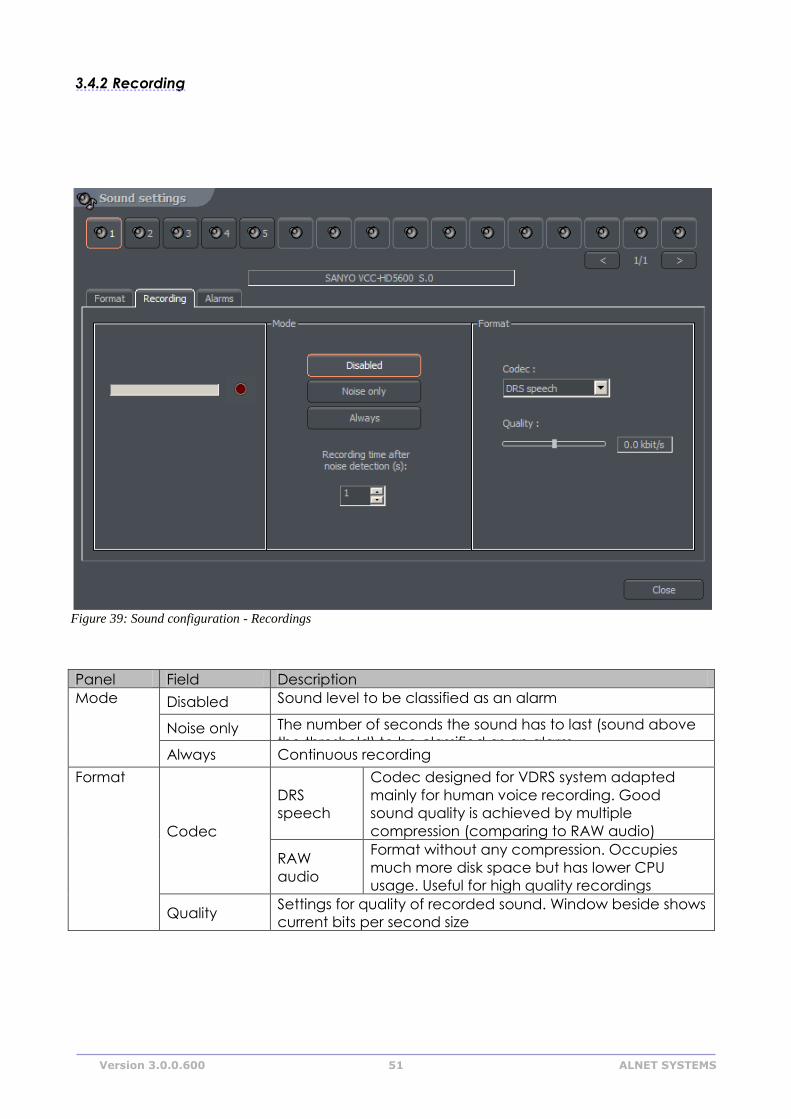
3.4.2 Recording
Panel Field Description
Mode
Disabled Sound level to be classified as an alarm
Noise only The number of seconds the sound has to last (sound above
the threshold) to be classified as an alarm Always Continuous recording
Format
Codec
DRS
speech
Codec designed for VDRS system adapted
mainly for human voice recording. Good
sound quality is achieved by multiple
compression (comparing to RAW audio)
RAW
audio
Format without any compression. Occupies
much more disk space but has lower CPU
usage. Useful for high quality recordings
Quality Settings for quality of recorded sound. Window beside shows
current bits per second size
Figure 39: Sound configuration - Recordings
Version 3.0.0.600 52 ALNET SYSTEMS
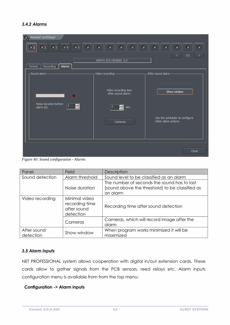
3.4.2 Alarms
Panel Field Description
Sound detection Alarm threshold Sound level to be classified as an alarm
Noise duration
The number of seconds the sound has to last
(sound above the threshold) to be classified as
an alarm
Video recording Minimal video
recording time
after sound
detection
Recording time after sound detection
Cameras Cameras, which will record image after the
alarm
After sound
detection Show window
When program works minimized it will be
maximized
3.5 Alarm inputs
NET PROFESSIONAL system allows cooperation with digital in/out extension cards. These
cards allow to gather signals from the PCB sensors, reed relays etc. Alarm inputs
configuration menu is available from from the top menu:
Configuration -> Alarm inputs
Figure 40: Sound configuration - Alarms
Version 3.0.0.600 53 ALNET SYSTEMS
Figure 42: Alarm inputs - Alarms
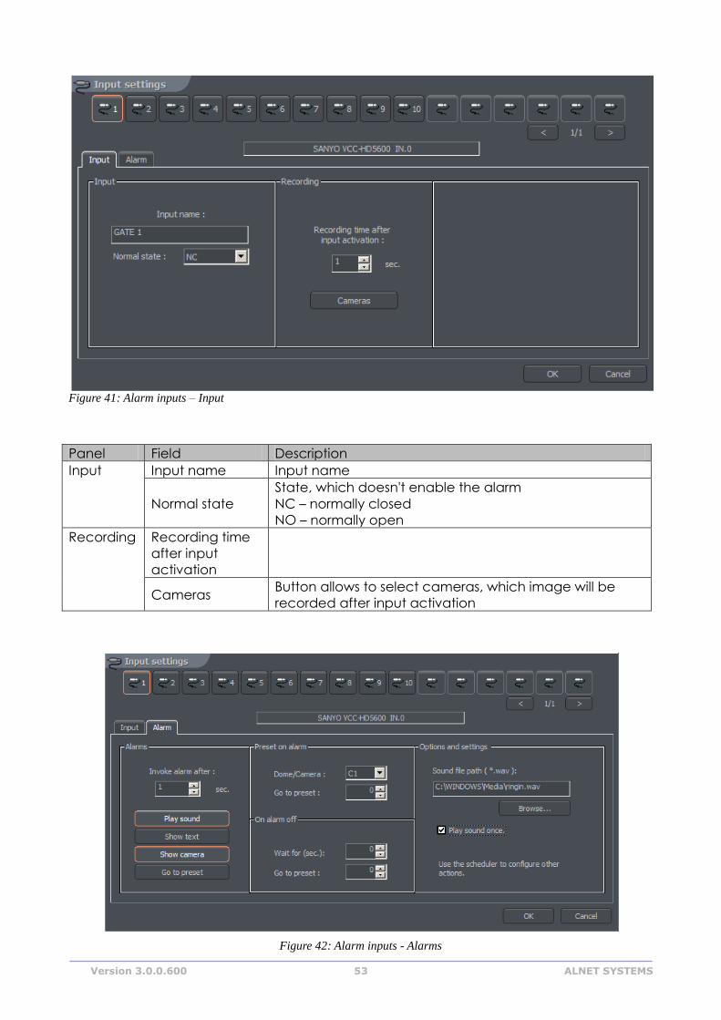
Panel Field Description
Input Input name Input name
Normal state
State, which doesn't enable the alarm
NC – normally closed
NO – normally open
Recording Recording time
after input
activation
Cameras Button allows to select cameras, which image will be
recorded after input activation
Figure 41: Alarm inputs – Input
Version 3.0.0.600 54 ALNET SYSTEMS
Panel Field Description
Alarms Play sound Plays sound from the "settings" panel in current window
Show text Shows notifications which pop up over the VDRS icon in tray
Show win-
dow When program is minimized it will maximize after the alarm
Go to pre-
set Sets the dome on the preset chosen in panel beside
Invoke
alarm after
:
Time before input activation and raising the alarm
Preset on
alarm Dome
List of available cameras. It is necessary to choose the dome
camera
Go to pre-
set
Dome position, to which camera should go after the alarm
Defining presets was described in paragraph 3.3.9
On alarm
off
Wait for
(sec)
Time, after which the dome moves to the preset defined be-
low
Go to pre-
set The position the dome goes after the finished alarm
Options
and settings
Path to the sound file, which will be played during the alarm
Play sound once
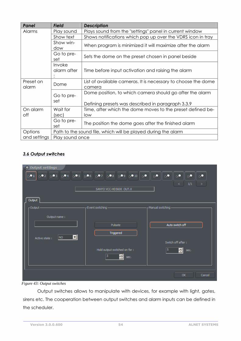
3.6 Output switches
Output switches allows to manipulate with devices, for example with light, gates,
sirens etc. The cooperation between output switches and alarm inputs can be defined in
the scheduler.
Figure 43: Output switches
Version 3.0.0.600 55 ALNET SYSTEMS
Panel Field Description
Output Output name Name of the output, for example "Gate"
Active state State, which doesn't enable the switch
NC – normally closed
NO – normally open
Event swi-
tching
Activation by the events defined in the scheduler
Pulsate The switch will pulsate (will change it's state every 1 se-
cond)
Triggered Enables the possibility to define the time of switch acti-
vation
Hold output
switched on
for :
Time of switch activation
Manual swi-
tching
Auto switch off If user manually activates the switch the system can au-
tomatically disable the switch
Switch off after
:
Time to elapse before the auto switch off
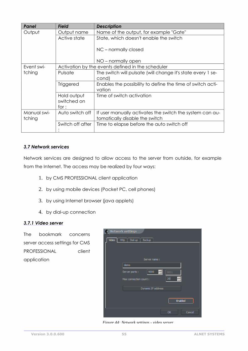
3.7 Network services
Network services are designed to allow access to the server from outside, for example
from the Internet. The access may be realized by four ways:
1. by CMS PROFESSIONAL client application
2. by using mobile devices (Pocket PC, cell phones)
3. by using Internet browser (java applets)
4. by dial-up connection
3.7.1 Video server
The bookmark concerns
server access settings for CMS
PROFESSIONAL client
application
Figure 44: Network settings - video server
Version 3.0.0.600 56 ALNET SYSTEMS
Field Description
Server name Name of the video server
Server ports NET PROFESSIONAL uses two (following) ports. Here You can define port
for connection between server and client. By default it's port 9000 (and
the following – 9001)
Max.
Connection
count
Number represents the maximum amount of simultaneous connections.
When the bandwidth is low it is possible to limit the number of
connections
Dynamic IP
address
This option allows to use ALNET DNS server. When using the connection
with dynamic IP address it's very difficult and sometimes impossible to
connect to the server because dynamic IP address can change even
several times a day. The solution is to register a domain. By the first
configuration of the Network Services, if the option is marked, the form
will appear. To register domain it is necessary to fill this form. These
subject will be described in the further part of the manual.
Enabled/Disab
led
Enables/Disables the access to the server from outside network
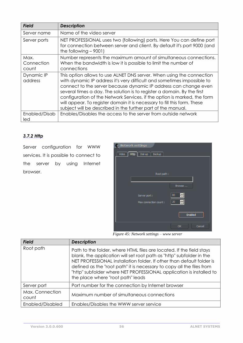
3.7.2 Http
Server configuration for WWW
services. It is possible to connect to
the server by using Internet
browser.
Field Description
Root path Path to the folder, where HTML files are located. If the field stays
blank, the application will set root path as "http" subfolder in the
NET PROFESSIONAL installation folder. If other than default folder is
defined as the "root path" it is necessary to copy all the files from
"http" subfolder where NET PROFESSIONAL application is installed to
the place where "root path" leads
Server port Port number for the connection by Internet browser
Max. Connection
count Maximum number of simultaneous connections
Enabled/Disabled Enables/Disables the WWW server service
Figure 45: Network settings – www server

Version 3.0.0.600 57 ALNET SYSTEMS
To test the http connection You can type local host number in Your Internet
browser http://127.0.0.1/
By default java applet connects to the AL-NET demo server. Applet consists of the
following windows:
Window with image parameters.
Changes refer to all of the cameras
Frame – quality of the frame
Delta – quality of the Delta frame
Resolution
Number of frames per second
The list of cameras is on the right side of the window. Clicking on the camera name will
open/close the window with camera view.
Main applet window. It contains a list of
active connections, alarm inputs and
output switches control module.
Opens a window with connections list. Choosing the connection from the active
connections list and clicking the icon will disconnect from this particular server.
Opens a window with image parameters
To add or modify network connection parameters it is necessary to edit and modify
index.htm file, which is placed in the folder defined in http settings. In the file there are
some connections created by default. One block refers to one connections. It consists of
five parameters:
Connection name
<param name="Server1Name" value="localhost">
Server address
<param name="Server1Address" value="127.0.0.1">
Pot number
<param name="Server1Port" value="9000">
User name
Figure 42: Java applet – camera settings
Version 3.0.0.600 58 ALNET SYSTEMS
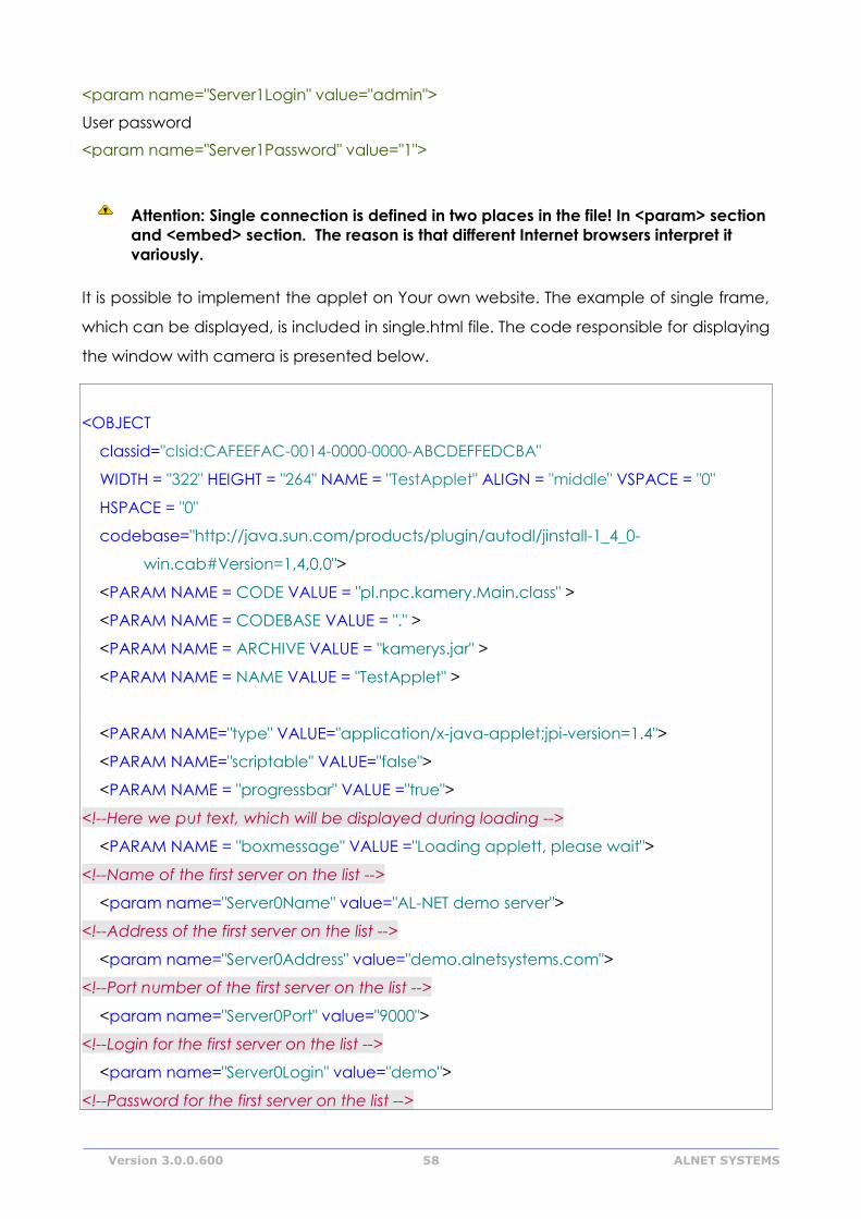
<param name="Server1Login" value="admin">
User password
<param name="Server1Password" value="1">
Attention: Single connection is defined in two places in the file! In <param> section
and <embed> section. The reason is that different Internet browsers interpret it
variously.
It is possible to implement the applet on Your own website. The example of single frame,
which can be displayed, is included in single.html file. The code responsible for displaying
the window with camera is presented below.
<OBJECT
classid="clsid:CAFEEFAC-0014-0000-0000-ABCDEFFEDCBA"
WIDTH = "322" HEIGHT = "264" NAME = "TestApplet" ALIGN = "middle" VSPACE = "0"
HSPACE = "0"
codebase="http://java.sun.com/products/plugin/autodl/jinstall-1_4_0-
win.cab#Version=1,4,0,0">
<PARAM NAME = CODE VALUE = "pl.npc.kamery.Main.class" >
<PARAM NAME = CODEBASE VALUE = "." >
<PARAM NAME = ARCHIVE VALUE = "kamerys.jar" >
<PARAM NAME = NAME VALUE = "TestApplet" >
<PARAM NAME="type" VALUE="application/x-java-applet;jpi-version=1.4">
<PARAM NAME="scriptable" VALUE="false">
<PARAM NAME = "progressbar" VALUE ="true">
<!--Here we put text, which will be displayed during loading -->
<PARAM NAME = "boxmessage" VALUE ="Loading applett, please wait">
<!--Name of the first server on the list -->
<param name="Server0Name" value="AL-NET demo server">
<!--Address of the first server on the list -->
<param name="Server0Address" value="demo.alnetsystems.com">
<!--Port number of the first server on the list -->
<param name="Server0Port" value="9000">
<!--Login for the first server on the list -->
<param name="Server0Login" value="demo">
<!--Password for the first server on the list -->
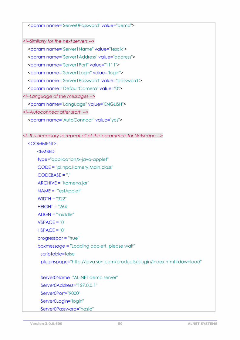
Version 3.0.0.600 59 ALNET SYSTEMS
<param name="Server0Password" value="demo">
<!--Similarly for the next servers -->
<param name="Server1Name" value="tescik">
<param name="Server1Address" value="address">
<param name="Server1Port" value="1111">
<param name="Server1Login" value="login">
<param name="Server1Password" value="password">
<param name="DefaultCamera" value="0">
<!--Language of the messages -->
<param name="Language" value="ENGLISH">
<!--Autoconnect after start -->
<param name="AutoConnect" value="yes">
<!--It is necessary to repeat all of the parameters for Netscape -->
<COMMENT>
<EMBED
type="application/x-java-applet"
CODE = "pl.npc.kamery.Main.class"
CODEBASE = "."
ARCHIVE = "kamerys.jar"
NAME = "TestApplet"
WIDTH = "322"
HEIGHT = "264"
ALIGN = "middle"
VSPACE = "0"
HSPACE = "0"
progressbar = "true"
boxmessage = "Loading applett, please wait"
scriptable=false
pluginspage="http://java.sun.com/products/plugin/index.html#download"
Server0Name="AL-NET demo server"
Server0Address="127.0.0.1"
Server0Port="9000"
Server0Login="login"
Server0Password="hasło"
Version 3.0.0.600 60 ALNET SYSTEMS
DefaultCamera="0"
Language="ENGLISH"
AutoConnect="yes">
</EMBED>
</COMMENT>
</OBJECT>
3.7.3 Video for Java
This panel controls all the image transfer parameters for the cell-phone client
applications made for JAVA environment.
Field Description
Server port Port number for the connection
Max. Connection
count
Max number of simultaneous connections
Picture quality Quality of transmitted image
Enabled/Disabled Enables/Disables the video server for JAVA
3.7.4 Dial up
Dial up connection can be used when there is no Internet connection or the
Internet connection failure occurs. NET PROFESSIONAL allows both making and receiving
calls. The bookmark shows available modem connections. If there in no connection on
the list, it has to be configured in Windows OS. Activity time option allows to define the
time range for the modem connections.
Figure 46: Network settings – dial-up server
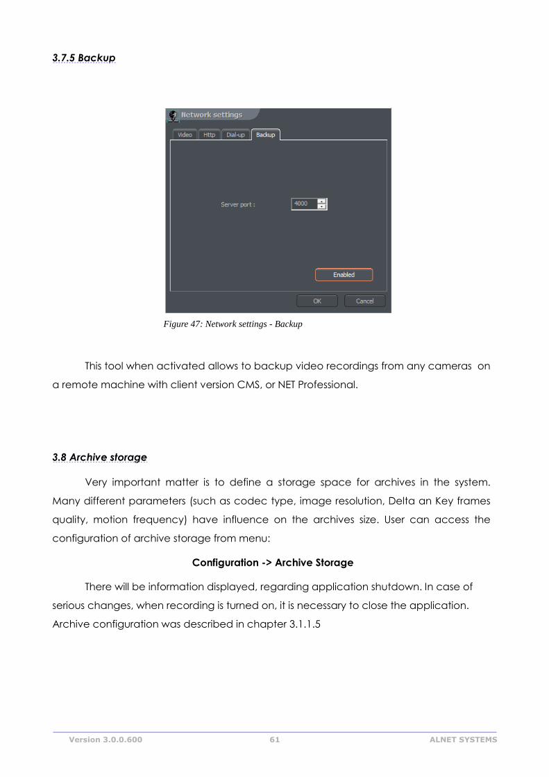
Version 3.0.0.600 61 ALNET SYSTEMS
3.7.5 Backup
This tool when activated allows to backup video recordings from any cameras on
a remote machine with client version CMS, or NET Professional.
3.8 Archive storage
Very important matter is to define a storage space for archives in the system.
Many different parameters (such as codec type, image resolution, Delta an Key frames
quality, motion frequency) have influence on the archives size. User can access the
configuration of archive storage from menu:
Configuration -> Archive Storage
There will be information displayed, regarding application shutdown. In case of
serious changes, when recording is turned on, it is necessary to close the application.
Archive configuration was described in chapter 3.1.1.5
Figure 47: Network settings - Backup
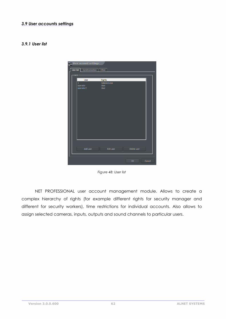
Version 3.0.0.600 62 ALNET SYSTEMS
3.9 User accounts settings
3.9.1 User list
Figure 48: User list
NET PROFESSIONAL user account management module. Allows to create a
complex hierarchy of rights (for example different rights for security manager and
different for security workers), time restrictions for individual accounts. Also allows to
assign selected cameras, inputs, outputs and sound channels to particular users.
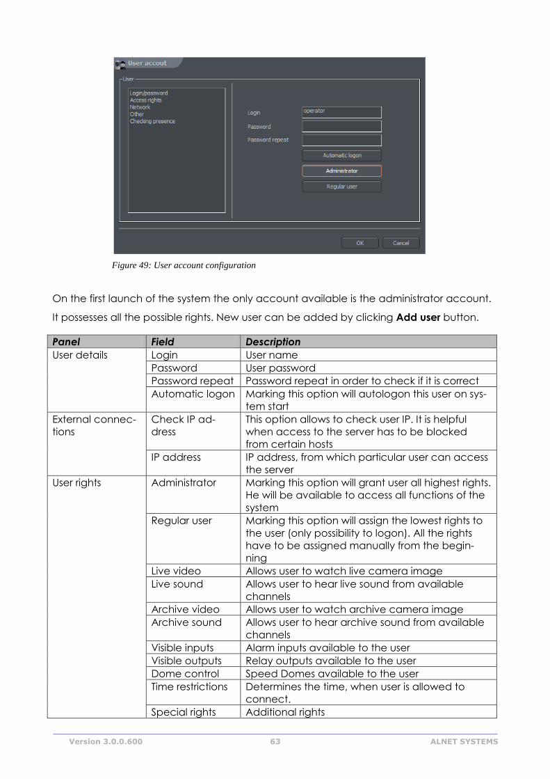
Version 3.0.0.600 63 ALNET SYSTEMS
On the first launch of the system the only account available is the administrator account.
It possesses all the possible rights. New user can be added by clicking Add user button.
Panel Field Description
User details Login User name
Password User password
Password repeat Password repeat in order to check if it is correct
Automatic logon Marking this option will autologon this user on sys-
tem start
External connec-
tions
Check IP ad-
dress
This option allows to check user IP. It is helpful
when access to the server has to be blocked
from certain hosts
IP address IP address, from which particular user can access
the server
User rights Administrator Marking this option will grant user all highest rights.
He will be available to access all functions of the
system
Regular user Marking this option will assign the lowest rights to
the user (only possibility to logon). All the rights
have to be assigned manually from the begin-
ning
Live video Allows user to watch live camera image
Live sound Allows user to hear live sound from available
channels
Archive video Allows user to watch archive camera image
Archive sound Allows user to hear archive sound from available
channels
Visible inputs Alarm inputs available to the user
Visible outputs Relay outputs available to the user
Dome control Speed Domes available to the user
Time restrictions Determines the time, when user is allowed to
connect.
Special rights Additional rights
Figure 49: User account configuration
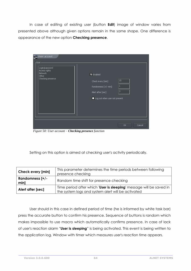
Version 3.0.0.600 64 ALNET SYSTEMS
In case of editing of existing user (button Edit) image of window varies from
presented above although given options remain in the same shape. One difference is
appearance of the new option Checking presence.
Setting on this option is aimed at checking user's activity periodically.
Check every [min] This parameter determines the time periods between following
presence checking
Randomness [+/-
min] Random time shift for presence checking
Alert after [sec] Time period after which 'User is sleeping' message will be saved in
the system logs and system alert will be activated
User should in this case in defined period of time (he is informed by white task bar)
press the accurate button to confirm his presence. Sequence of buttons is random which
makes impossible to use macro which automatically confirms presence. In case of lack
of user's reaction alarm ''User is sleeping” is being activated. This event is being written to
the application log. Window with timer which measures user's reaction time appears.
Figure 50: User account – Checking presence function
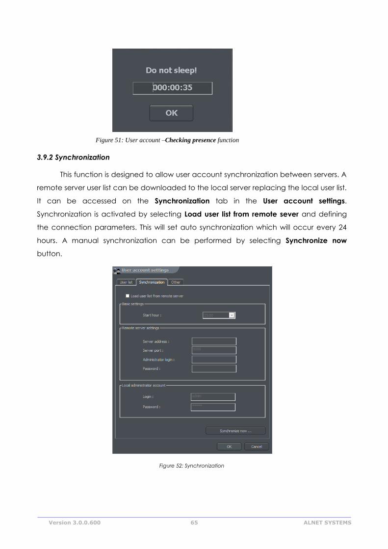
Version 3.0.0.600 65 ALNET SYSTEMS
3.9.2 Synchronization
This function is designed to allow user account synchronization between servers. A
remote server user list can be downloaded to the local server replacing the local user list.
It can be accessed on the Synchronization tab in the User account settings.
Synchronization is activated by selecting Load user list from remote sever and defining
the connection parameters. This will set auto synchronization which will occur every 24
hours. A manual synchronization can be performed by selecting Synchronize now
button.
Figure 52: Synchronization
Figure 51: User account –Checking presence function
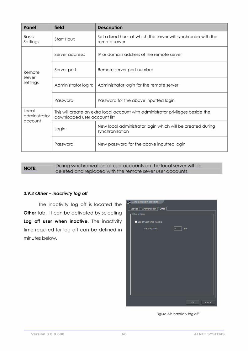
Version 3.0.0.600 66 ALNET SYSTEMS
Panel field Description
Basic
Settings Start Hour:
Set a fixed hour at which the server will synchronize with the
remote server
Remote
server
settings
Server address: IP or domain address of the remote server
Server port: Remote server port number
Administrator login: Administrator login for the remote server
Password: Password for the above inputted login
Local
administrator
account
This will create an extra local account with administrator privileges beside the
downloaded user account list
Login: New local administrator login which will be created during
synchronization
Password: New password for the above inputted login
NOTE: During synchronization all user accounts on the local server will be
deleted and replaced with the remote sever user accounts.
3.9.3 Other – inactivity log off
The inactivity log off is located the
Other tab. It can be activated by selecting
Log off user when inactive. The inactivity
time required for log off can be defined in
minutes below.
Figure 53: Inactivity log off
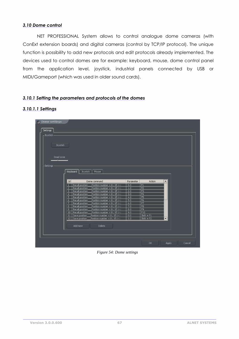
Version 3.0.0.600 67 ALNET SYSTEMS
3.10 Dome control
NET PROFESSIONAL System allows to control analogue dome cameras (with
ConExt extension boards) and digital cameras (control by TCP/IP protocol). The unique
function is possibility to add new protocols and edit protocols already implemented. The
devices used to control domes are for example: keyboard, mouse, dome control panel
from the application level, joystick, industrial panels connected by USB or
MIDI/Gameport (which was used in older sound cards).
3.10.1 Setting the parameters and protocols of the domes
3.10.1.1 Settings
Figure 54: Dome settings
Version 3.0.0.600 68 ALNET SYSTEMS
Panel Field Description
Control Enable Enables the dome control function in NET
PROFESSIONAL
Joystick Joystick
Activates joystick. If any error occurs the message will
appear
Dead zone Joystick "motion range" on which system will not react
Protocol This panel assigns dome control protocol to selected COM port. In order to
add a protocol select COM port, click "Set protocol" button and choose
the protocol from the list
Settings Settings which concern control commands. This panel is divided into three
sections: Keyboard, Joystick and Mouse. It is possible to add new
command and edit existing ones. To edit command double-click on
command name. To add command select "Add new" button
Dome command
Command name (describes it's action)
Parameter Parameter value, which is transmitted to the dome
during the command execution
Action Keyboard shortcut to selected command (for mouse
and joystick these options are permanently assigned to
their functions)
3.10.1.2 Protocols
Protocols located in the NET PROFESSIONAL system are recommended by
manufacturers. If there is no need to change their parameters. Before adding protocol to
application the technical specification should be obtained (for e.g. from dome
manufacturer) to fill in required gaps
AD/SENSORMATIC
AXIS
CANON VC-C4
COLOR CCD AN800's
ACTI-ACM85xx
DSCP
HISHARP (HSCP)
HN
HNHG

Version 3.0.0.600 69 ALNET SYSTEMS
HUAREN
HY
JFKJ
JVC
KALATEL1
KALATEL2
KALATEL KTD-312
KELI
LILIN PIH-717A
LILIN PIH-717
NV-2050P
PANASONIC-CONV
PANASONIC-NEW
PELCO 'D'
PELCO 'D' 9600
PELCO 'D' ver.4
PELCO 'P' 2400
PELCO 'P' 4800
PELCO 'P' ver.II
PHILIPS TC-8560
SAMSUNG
SONY EVI-D3x
SVE
TELECOM
VIDO B01
WD
ZC-NAF27
SONY-VISCA CAM
SONY-VISCA PTZ
DYNACOLOR
ACTI-CAM66xx
D-MAX SUPERIOR DSC-2xxS
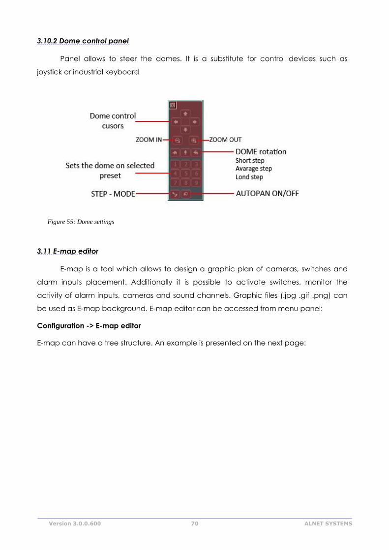
Version 3.0.0.600 70 ALNET SYSTEMS
3.10.2 Dome control panel
Panel allows to steer the domes. It is a substitute for control devices such as
joystick or industrial keyboard
3.11 E-map editor
E-map is a tool which allows to design a graphic plan of cameras, switches and
alarm inputs placement. Additionally it is possible to activate switches, monitor the
activity of alarm inputs, cameras and sound channels. Graphic files (.jpg .gif .png) can
be used as E-map background. E-map editor can be accessed from menu panel:
Configuration -> E-map editor
E-map can have a tree structure. An example is presented on the next page:
Figure 55: Dome settings
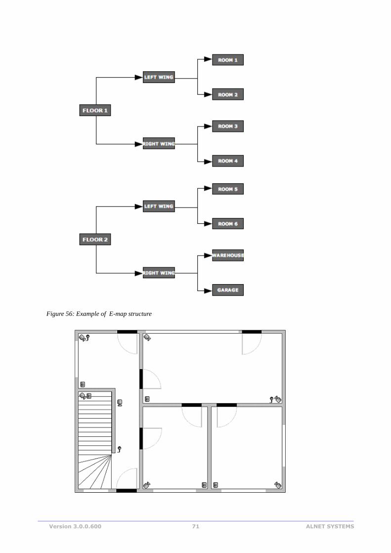
Version 3.0.0.600 71 ALNET SYSTEMS
Figure 56: Example of E-map structure
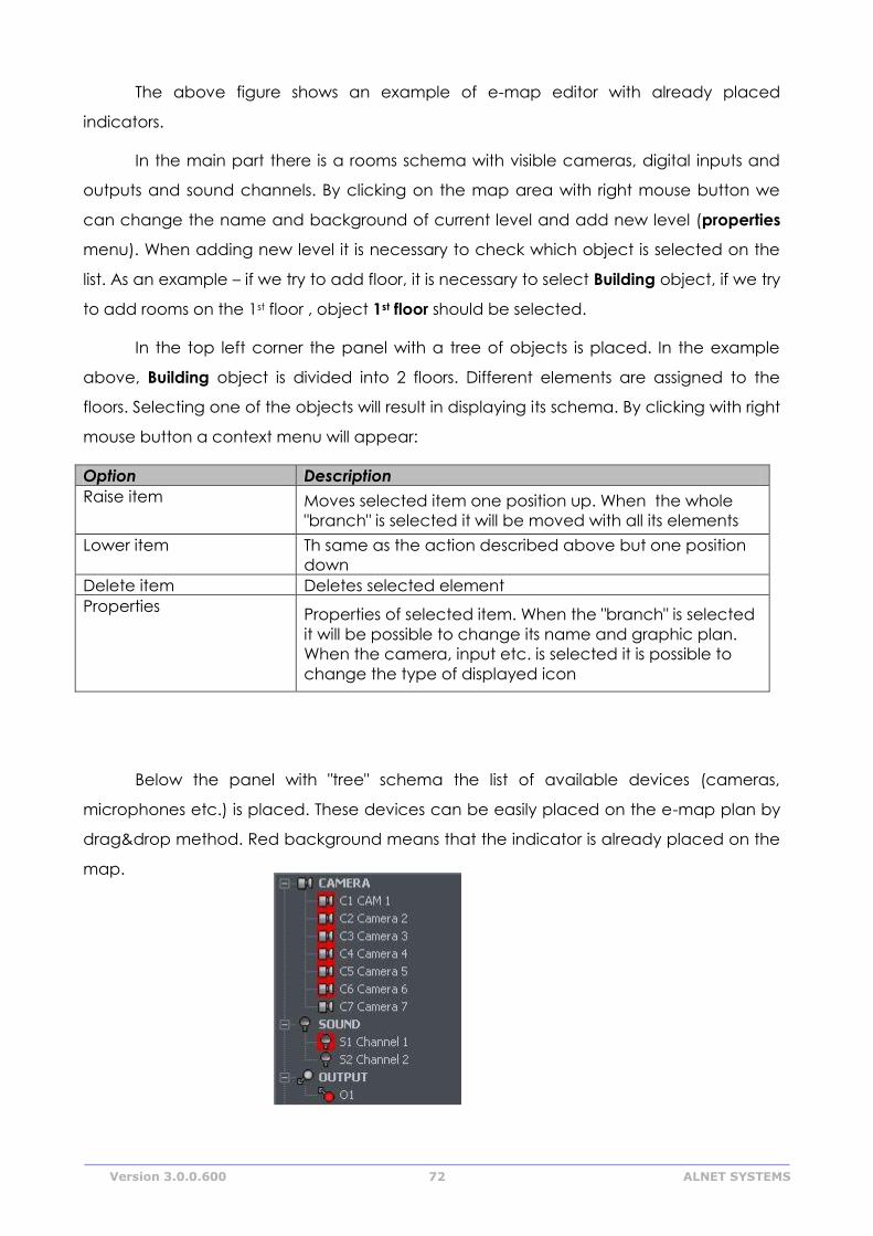
Version 3.0.0.600 72 ALNET SYSTEMS
The above figure shows an example of e-map editor with already placed
indicators.
In the main part there is a rooms schema with visible cameras, digital inputs and
outputs and sound channels. By clicking on the map area with right mouse button we
can change the name and background of current level and add new level (properties
menu). When adding new level it is necessary to check which object is selected on the
list. As an example – if we try to add floor, it is necessary to select Building object, if we try
to add rooms on the 1st floor , object 1st floor should be selected.
In the top left corner the panel with a tree of objects is placed. In the example
above, Building object is divided into 2 floors. Different elements are assigned to the
floors. Selecting one of the objects will result in displaying its schema. By clicking with right
mouse button a context menu will appear:
Option Description
Raise item Moves selected item one position up. When the whole
"branch" is selected it will be moved with all its elements
Lower item Th same as the action described above but one position
down
Delete item Deletes selected element
Properties Properties of selected item. When the "branch" is selected
it will be possible to change its name and graphic plan.
When the camera, input etc. is selected it is possible to
change the type of displayed icon
Below the panel with "tree" schema the list of available devices (cameras,
microphones etc.) is placed. These devices can be easily placed on the e-map plan by
drag&drop method. Red background means that the indicator is already placed on the
map.
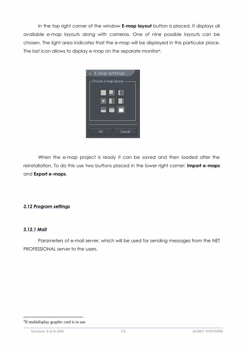
Version 3.0.0.600 73 ALNET SYSTEMS
In the top right corner of the window E-map layout button is placed. It displays all
available e-map layouts along with cameras. One of nine possible layouts can be
chosen. The light area indicates that the e-map will be displayed in this particular place.
The last icon allows to display e-map on the separate monitor4.
When the e-map project is ready it can be saved and then loaded after the
reinstallation. To do this use two buttons placed in the lower right corner: Import e-maps
and Export e-maps.
3.12 Program settings
3.12.1 Mail
Parameters of e-mail server, which will be used for sending messages from the NET
PROFESSIONAL server to the users.
4If multidisplay graphic card is in use
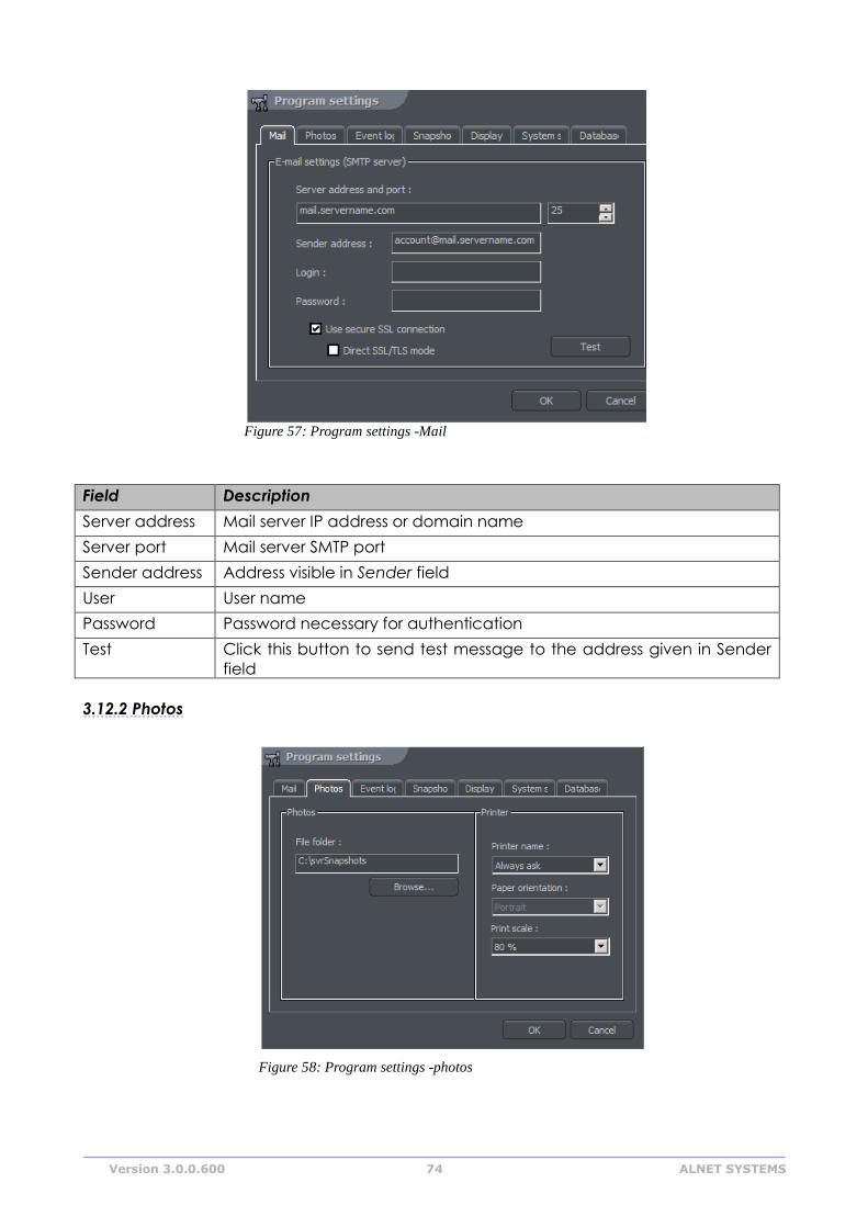
Version 3.0.0.600 74 ALNET SYSTEMS
Field Description
Server address Mail server IP address or domain name
Server port Mail server SMTP port
Sender address Address visible in Sender field
User User name
Password Password necessary for authentication
Test Click this button to send test message to the address given in Sender
field
3.12.2 Photos
Figure 58: Program settings -photos
Figure 57: Program settings -Mail
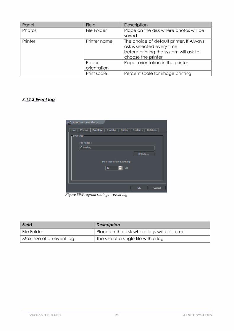
Version 3.0.0.600 75 ALNET SYSTEMS
Figure 59:Program settings – event log
Panel Field Description
Photos File Folder Place on the disk where photos will be
saved
Printer Printer name The choice of default printer. If Always
ask is selected every time
before printing the system will ask to
choose the printer
Paper
orientation
Paper orientation in the printer
Print scale Percent scale for image printing
3.12.3 Event log
Field Description
File Folder Place on the disk where logs will be stored
Max. size of an event log The size of a single file with a log
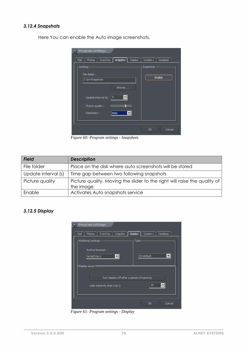
Version 3.0.0.600 76 ALNET SYSTEMS
3.12.4 Snapshots
Here You can enable the Auto image screenshots.
Field Description
File folder Place on the disk where auto screenshots will be stored
Update interval (s) Time gap between two following snapshots
Picture quality Picture quality. Moving the slider to the right will raise the quality of
the image
Enable Activates Auto snapshots service
3.12.5 Display
Figure 61: Program settings - Display
Figure 60: Program settings - Snapshots
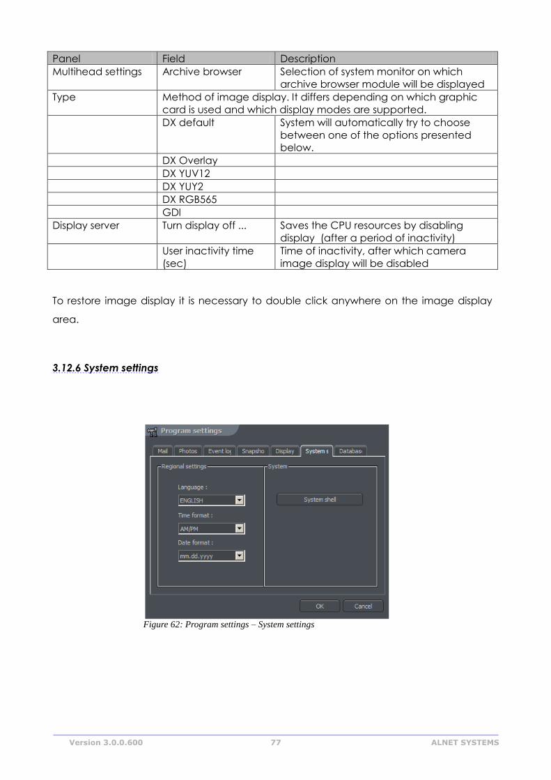
Version 3.0.0.600 77 ALNET SYSTEMS
Panel Field Description
Multihead settings Archive browser Selection of system monitor on which
archive browser module will be displayed
Type Method of image display. It differs depending on which graphic
card is used and which display modes are supported.
DX default System will automatically try to choose
between one of the options presented
below.
DX Overlay
DX YUV12
DX YUY2
DX RGB565
GDI
Display server Turn display off ... Saves the CPU resources by disabling
display (after a period of inactivity)
User inactivity time
(sec)
Time of inactivity, after which camera
image display will be disabled
To restore image display it is necessary to double click anywhere on the image display
area.
3.12.6 System settings
Figure 62: Program settings – System settings
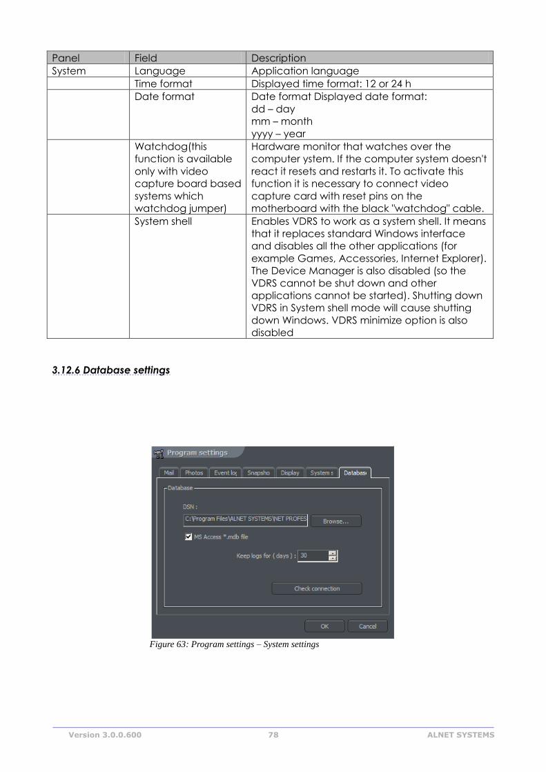
Version 3.0.0.600 78 ALNET SYSTEMS
Panel Field Description
System Language Application language
Time format Displayed time format: 12 or 24 h
Date format Date format Displayed date format:
dd – day
mm – month
yyyy – year
Watchdog(this
function is available
only with video
capture board based
systems which
watchdog jumper)
Hardware monitor that watches over the
computer ystem. If the computer system doesn't
react it resets and restarts it. To activate this
function it is necessary to connect video
capture card with reset pins on the
motherboard with the black "watchdog" cable.
System shell Enables VDRS to work as a system shell. It means
that it replaces standard Windows interface
and disables all the other applications (for
example Games, Accessories, Internet Explorer).
The Device Manager is also disabled (so the
VDRS cannot be shut down and other
applications cannot be started). Shutting down
VDRS in System shell mode will cause shutting
down Windows. VDRS minimize option is also
disabled
3.12.6 Database settings
Figure 63: Program settings – System settings
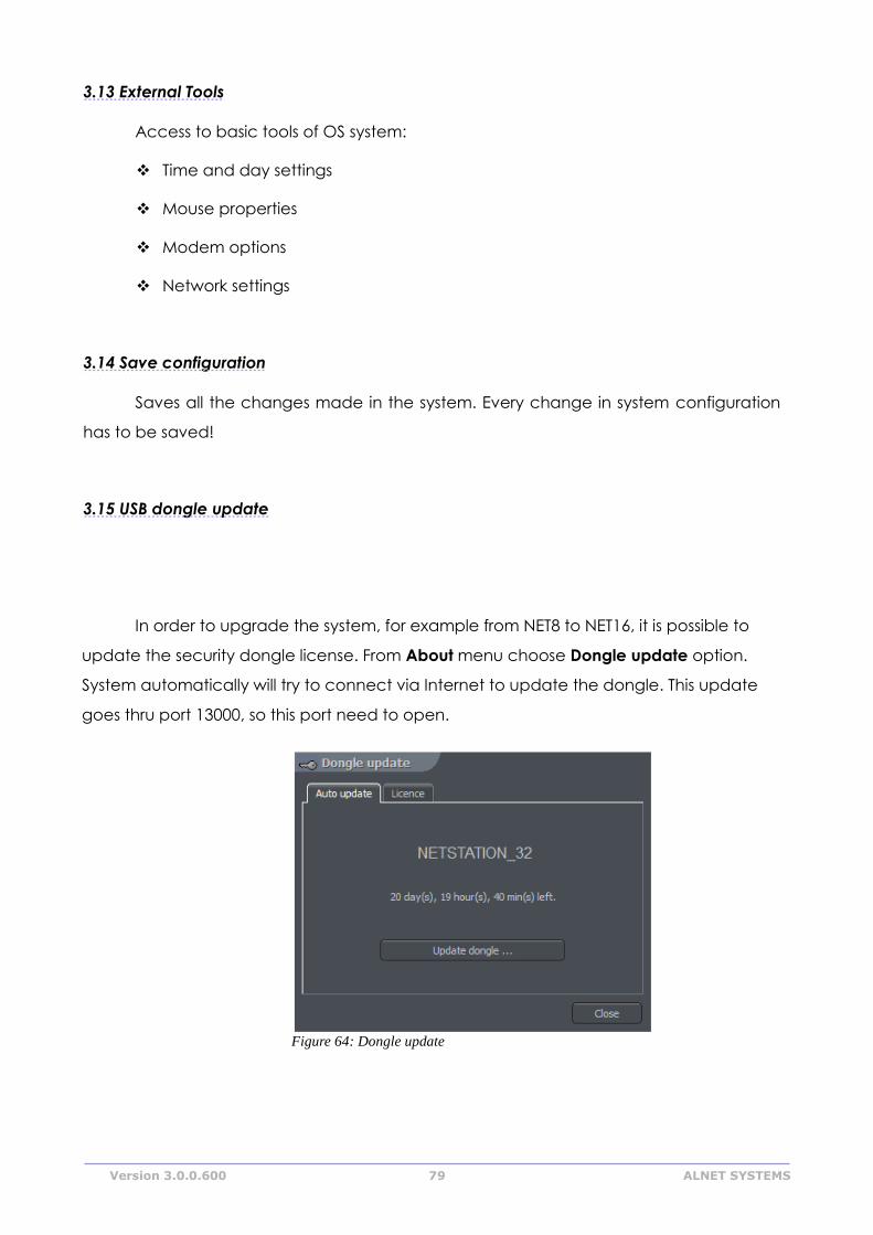
Version 3.0.0.600 79 ALNET SYSTEMS
3.13 External Tools
Access to basic tools of OS system:
Time and day settings
Mouse properties
Modem options
Network settings
3.14 Save configuration
Saves all the changes made in the system. Every change in system configuration
has to be saved!
3.15 USB dongle update
In order to upgrade the system, for example from NET8 to NET16, it is possible to
update the security dongle license. From About menu choose Dongle update option.
System automatically will try to connect via Internet to update the dongle. This update
goes thru port 13000, so this port need to open.
Figure 64: Dongle update
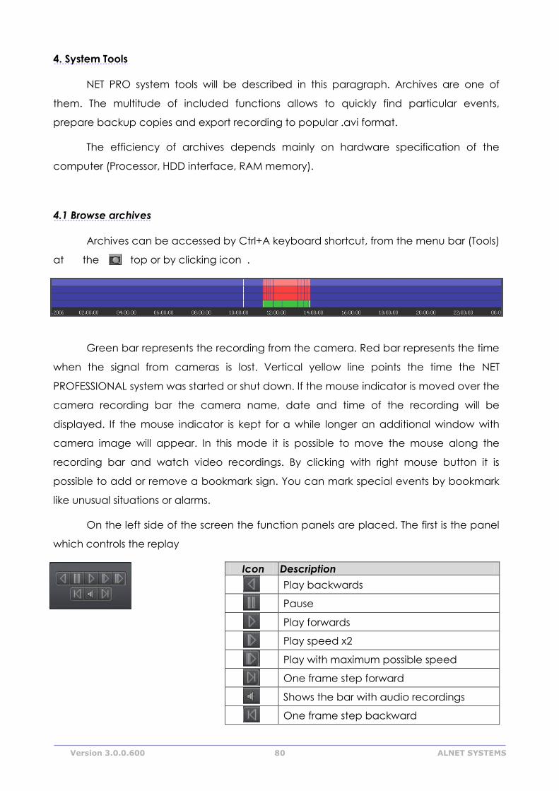
Version 3.0.0.600 80 ALNET SYSTEMS
4. System Tools
NET PRO system tools will be described in this paragraph. Archives are one of
them. The multitude of included functions allows to quickly find particular events,
prepare backup copies and export recording to popular .avi format.
The efficiency of archives depends mainly on hardware specification of the
computer (Processor, HDD interface, RAM memory).
4.1 Browse archives
Archives can be accessed by Ctrl+A keyboard shortcut, from the menu bar (Tools)
at the top or by clicking icon .
Green bar represents the recording from the camera. Red bar represents the time
when the signal from cameras is lost. Vertical yellow line points the time the NET
PROFESSIONAL system was started or shut down. If the mouse indicator is moved over the
camera recording bar the camera name, date and time of the recording will be
displayed. If the mouse indicator is kept for a while longer an additional window with
camera image will appear. In this mode it is possible to move the mouse along the
recording bar and watch video recordings. By clicking with right mouse button it is
possible to add or remove a bookmark sign. You can mark special events by bookmark
like unusual situations or alarms.
On the left side of the screen the function panels are placed. The first is the panel
which controls the replay
Icon Description
Play backwards
Pause
Play forwards
Play speed x2
Play with maximum possible speed
One frame step forward
Shows the bar with audio recordings
One frame step backward
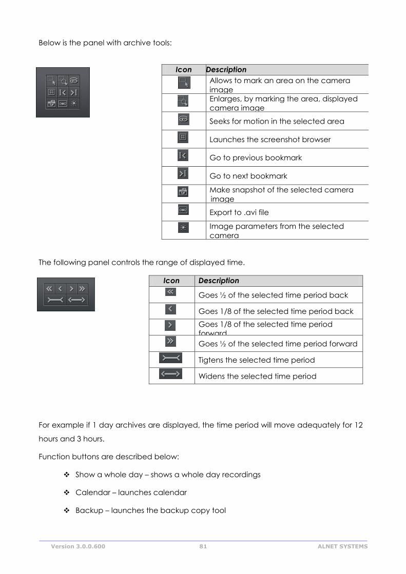
Version 3.0.0.600 81 ALNET SYSTEMS
Below is the panel with archive tools:
Icon Description
Allows to mark an area on the camera
image
Enlarges, by marking the area, displayed
camera image
Seeks for motion in the selected area
Launches the screenshot browser
Go to previous bookmark
Go to next bookmark
Make snapshot of the selected camera
image
Export to .avi file
Image parameters from the selected
camera
The following panel controls the range of displayed time.
Icon Description
Goes ½ of the selected time period back
Goes 1/8 of the selected time period back
Goes 1/8 of the selected time period
forward
Goes ½ of the selected time period forward
Tigtens the selected time period
Widens the selected time period
For example if 1 day archives are displayed, the time period will move adequately for 12
hours and 3 hours.
Function buttons are described below:
Show a whole day – shows a whole day recordings
Calendar – launches calendar
Backup – launches the backup copy tool
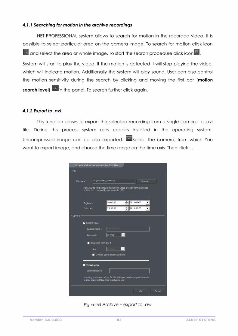
Version 3.0.0.600 82 ALNET SYSTEMS
4.1.1 Searching for motion in the archive recordings
NET PROFESSIONAL system allows to search for motion in the recorded video. It is
possible to select particular area on the camera image. To search for motion click icon
and select the area or whole image. To start the search procedure click icon .
System will start to play the video. If the motion is detected it will stop playing the video,
which will indicate motion. Additionally the system will play sound. User can also control
the motion sensitivity during the search by clicking and moving the first bar (motion
search level) in the panel. To search further click again.
4.1.2 Export to .avi
This function allows to export the selected recording from a single camera to .avi
file. During this process system uses codecs installed in the operating system.
Uncompressed image can be also exported. Select the camera, from which You
want to export image, and choose the time range on the time axis. Then click .
Figure 65 Archive – export to .avi
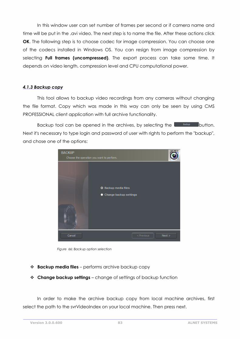
Version 3.0.0.600 83 ALNET SYSTEMS
In this window user can set number of frames per second or if camera name and
time will be put in the .avi video. The next step is to name the file. After these actions click
OK. The following step is to choose codec for image compression. You can choose one
of the codecs installed in Windows OS. You can resign from image compression by
selecting Full frames (uncompressed). The export process can take some time. It
depends on video length, compression level and CPU computational power.
4.1.3 Backup copy
This tool allows to backup video recordings from any cameras without changing
the file format. Copy which was made in this way can only be seen by using CMS
PROFESSIONAL client application with full archive functionality.
Backup tool can be opened in the archives, by selecting the button.
Next it's necessary to type login and password of user with rights to perform the "backup",
and chose one of the options:
Figure 66: Backup option selection
Backup media files – performs archive backup copy
Change backup settings – change of settings of backup function
In order to make the archive backup copy from local machine archives, first
select the path to the svrVideoIndex on your local machine. Then press next.
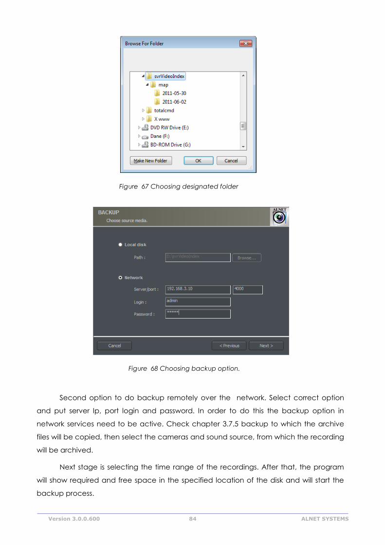
Version 3.0.0.600 84 ALNET SYSTEMS
Figure 67 Choosing designated folder
Figure 68 Choosing backup option.
Second option to do backup remotely over the network. Select correct option
and put server Ip, port login and password. In order to do this the backup option in
network services need to be active. Check chapter 3.7.5 backup to which the archive
files will be copied, then select the cameras and sound source, from which the recording
will be archived.
Next stage is selecting the time range of the recordings. After that, the program
will show required and free space in the specified location of the disk and will start the
backup process.
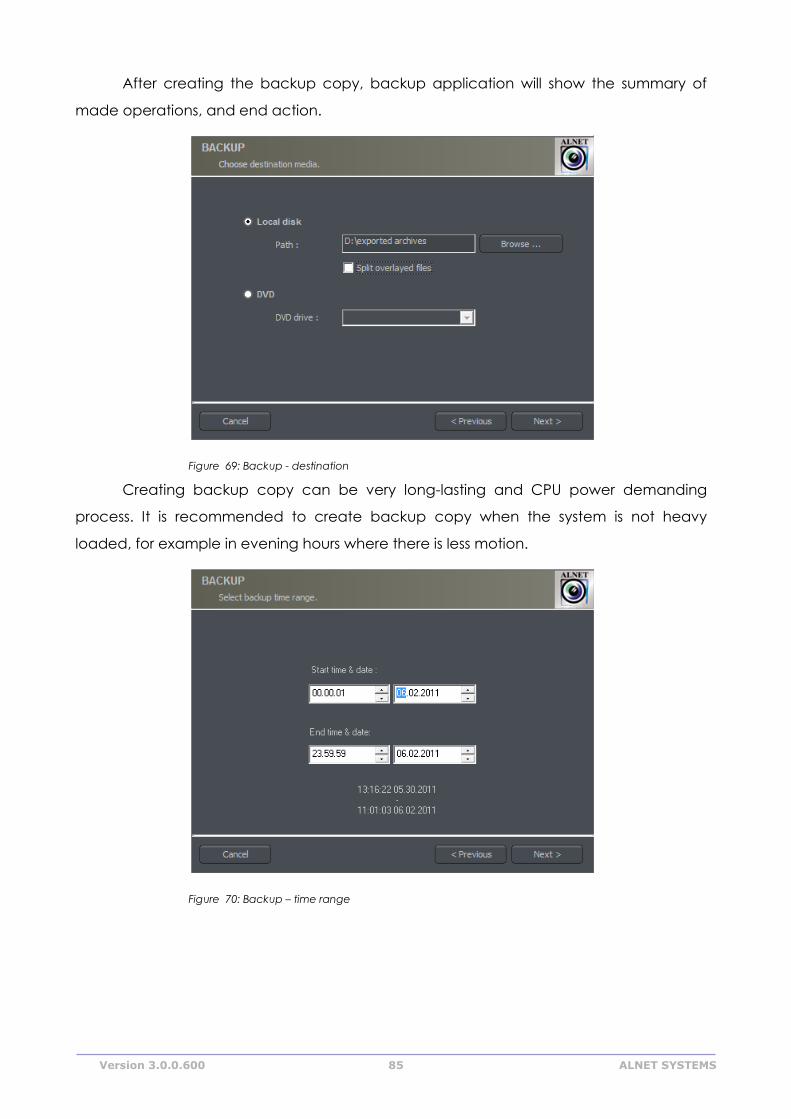
Version 3.0.0.600 85 ALNET SYSTEMS
After creating the backup copy, backup application will show the summary of
made operations, and end action.
Figure 69: Backup - destination
Creating backup copy can be very long-lasting and CPU power demanding
process. It is recommended to create backup copy when the system is not heavy
loaded, for example in evening hours where there is less motion.
Figure 70: Backup – time range
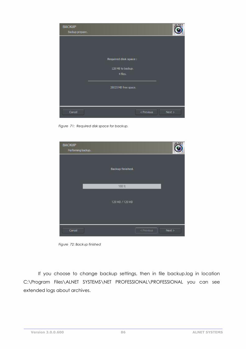
Version 3.0.0.600 86 ALNET SYSTEMS
Figure 71: Required disk space for backup.
Figure 72: Backup finished
If you choose to change backup settings, then in file backup.log in location
C:\Program Files\ALNET SYSTEMS\NET PROFESSIONAL\PROFESSIONAL you can see
extended logs about archives.
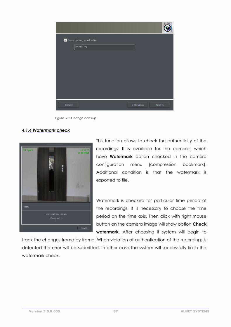
Version 3.0.0.600 87 ALNET SYSTEMS
Figure 73: Change backup
4.1.4 Watermark check
This function allows to check the authenticity of the
recordings. It is available for the cameras which
have Watermark option checked in the camera
configuration menu (compression bookmark).
Additional condition is that the watermark is
exported to file.
Watermark is checked for particular time period of
the recordings. It is necessary to choose the time
period on the time axis. Then click with right mouse
button on the camera image will show option Check
watermark. After choosing it system will begin to
track the changes frame by frame. When violation of authentication of the recordings is
detected the error will be submitted. In other case the system will successfully finish the
watermark check.
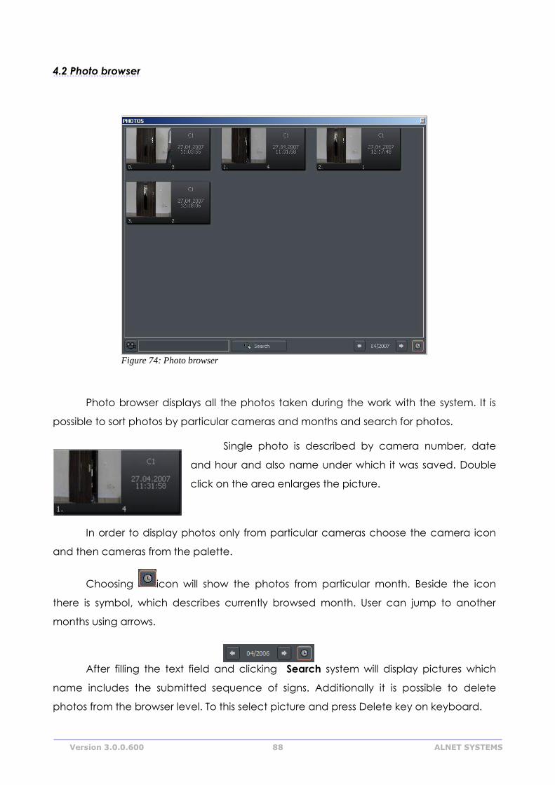
Version 3.0.0.600 88 ALNET SYSTEMS
4.2 Photo browser
Photo browser displays all the photos taken during the work with the system. It is
possible to sort photos by particular cameras and months and search for photos.
Single photo is described by camera number, date
and hour and also name under which it was saved. Double
click on the area enlarges the picture.
In order to display photos only from particular cameras choose the camera icon
and then cameras from the palette.
Choosing icon will show the photos from particular month. Beside the icon
there is symbol, which describes currently browsed month. User can jump to another
months using arrows.
After filling the text field and clicking Search system will display pictures which
name includes the submitted sequence of signs. Additionally it is possible to delete
photos from the browser level. To this select picture and press Delete key on keyboard.
Figure 74: Photo browser
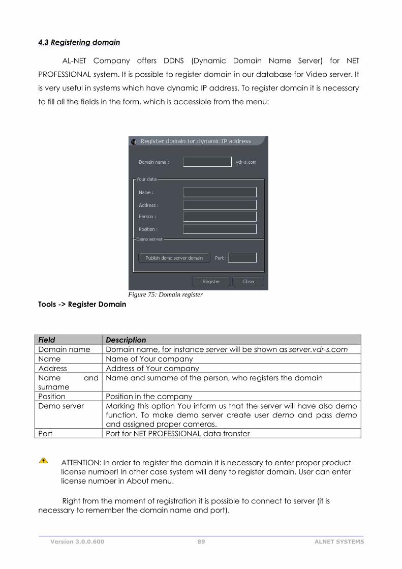
Version 3.0.0.600 89 ALNET SYSTEMS
4.3 Registering domain
AL-NET Company offers DDNS (Dynamic Domain Name Server) for NET
PROFESSIONAL system. It is possible to register domain in our database for Video server. It
is very useful in systems which have dynamic IP address. To register domain it is necessary
to fill all the fields in the form, which is accessible from the menu:
Tools -> Register Domain
Field Description
Domain name Domain name, for instance server will be shown as server.vdr-s.com
Name Name of Your company
Address Address of Your company
Name and
surname
Name and surname of the person, who registers the domain
Position Position in the company
Demo server Marking this option You inform us that the server will have also demo
function. To make demo server create user demo and pass demo
and assigned proper cameras.
Port Port for NET PROFESSIONAL data transfer
ATTENTION: In order to register the domain it is necessary to enter proper product
license number! In other case system will deny to register domain. User can enter
license number in About menu.
Right from the moment of registration it is possible to connect to server (it is
necessary to remember the domain name and port).
Figure 75: Domain register
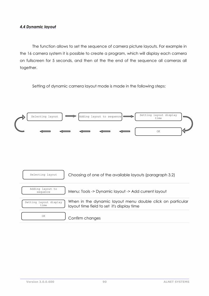
Version 3.0.0.600 90 ALNET SYSTEMS
4.4 Dynamic layout
The function allows to set the sequence of camera picture layouts. For example in
the 16 camera system it is possible to create a program, which will display each camera
on fullscreen for 5 seconds, and then at the the end of the sequence all cameras all
together.
Setting of dynamic camera layout mode is made in the following steps:
Choosing of one of the available layouts (paragraph 3.2)
Menu: Tools -> Dynamic layout -> Add current layout
When in the dynamic layout menu double click on particular
layout time field to set it's display time
Confirm changes
OK
Setting layout display
time
Adding layout to
sequence
Selecting layout
Selecting layout Adding layout to sequence
Setting layout display
time
OK
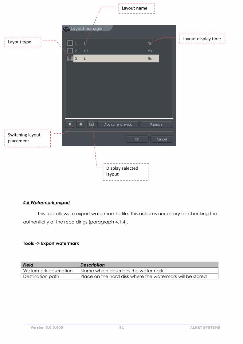
Version 3.0.0.600 91 ALNET SYSTEMS
4.5 Watermark export
This tool allows to export watermark to file. This action is necessary for checking the
authenticity of the recordings (paragraph 4.1.4).
Tools -> Export watermark
Field Description
Watermark description Name which describes the watermark
Destination path Place on the hard disk where the watermark will be stored
Layout name
Layout type Layout display time
Switching layout placement
Display selected layout
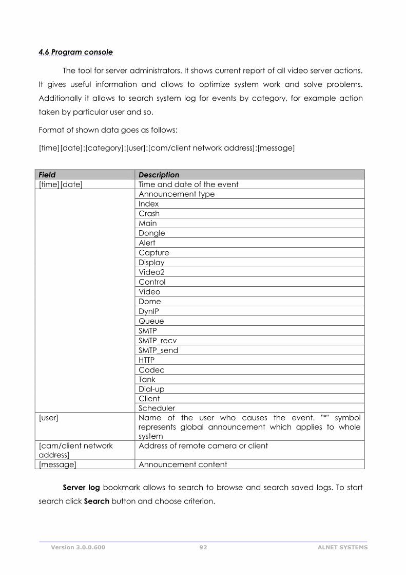
Version 3.0.0.600 92 ALNET SYSTEMS
4.6 Program console
The tool for server administrators. It shows current report of all video server actions.
It gives useful information and allows to optimize system work and solve problems.
Additionally it allows to search system log for events by category, for example action
taken by particular user and so.
Format of shown data goes as follows:
[time][date]:[category]:[user]:[cam/client network address]:[message]
Field Description
[time][date] Time and date of the event
Announcement type
Index
Crash
Main
Dongle
Alert
Capture
Display
Video2
Control
Video
Dome
DynIP
Queue
SMTP
SMTP_recv
SMTP_send
HTTP
Codec
Tank
Dial-up
Client
Scheduler
[user] Name of the user who causes the event. "*" symbol
represents global announcement which applies to whole
system
[cam/client network
address]
Address of remote camera or client
[message] Announcement content
Server log bookmark allows to search to browse and search saved logs. To start
search click Search button and choose criterion.
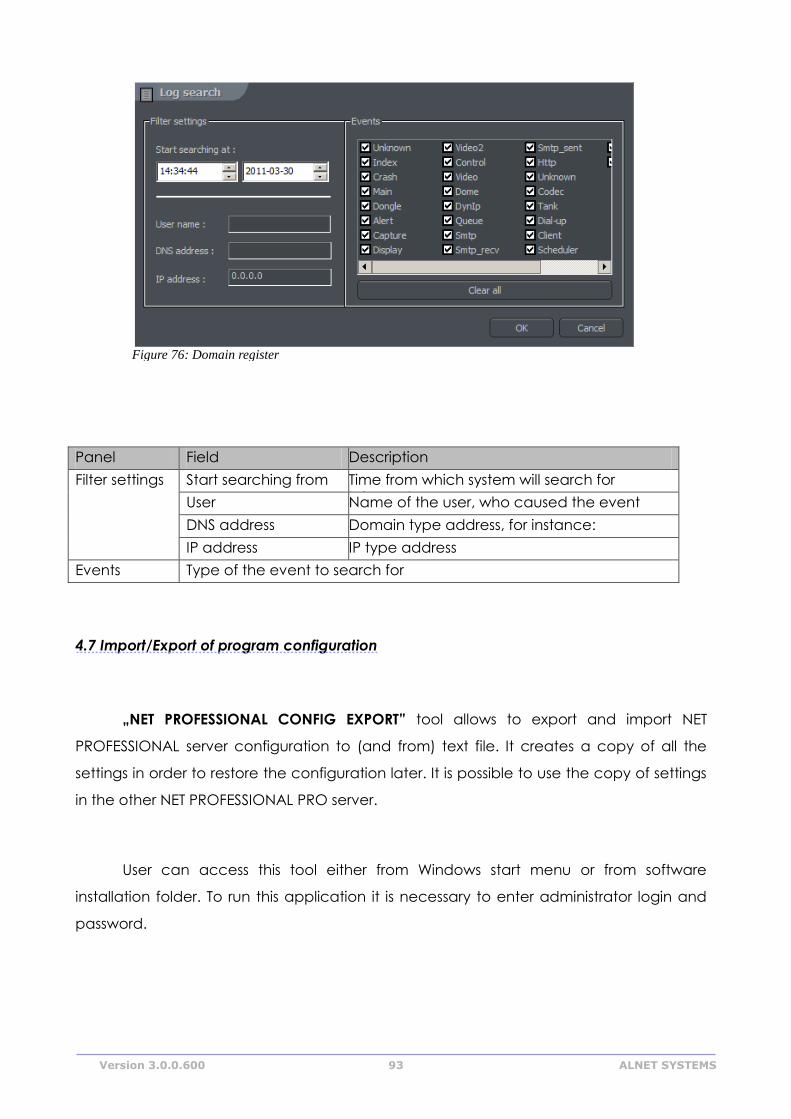
Version 3.0.0.600 93 ALNET SYSTEMS
Panel Field Description
Filter settings Start searching from Time from which system will search for
information User Name of the user, who caused the event
DNS address Domain type address, for instance:
camera.web.com IP address IP type address
Events Type of the event to search for
4.7 Import/Export of program configuration
„NET PROFESSIONAL CONFIG EXPORT” tool allows to export and import NET
PROFESSIONAL server configuration to (and from) text file. It creates a copy of all the
settings in order to restore the configuration later. It is possible to use the copy of settings
in the other NET PROFESSIONAL PRO server.
User can access this tool either from Windows start menu or from software
installation folder. To run this application it is necessary to enter administrator login and
password.
Figure 76: Domain register
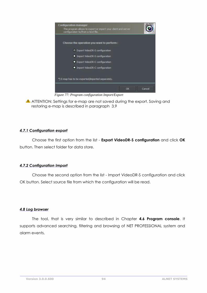
Version 3.0.0.600 94 ALNET SYSTEMS
ATTENTION: Settings for e-map are not saved during the export. Saving and
restoring e-map is described in paragraph 3.9
4.7.1 Configuration export
Choose the first option from the list - Export VideoDR-S configuration and click OK
button. Then select folder for data store.
4.7.2 Configuration Import
Choose the second option from the list - Import VideoDR-S configuration and click
OK button. Select source file from which the configuration will be read.
4.8 Log browser
The tool, that is very similar to described in Chapter 4.6 Program console. It
supports advanced searching, filtering and browsing of NET PROFESSIONAL system and
alarm events.
Figure 77: Program configuration Import/Export
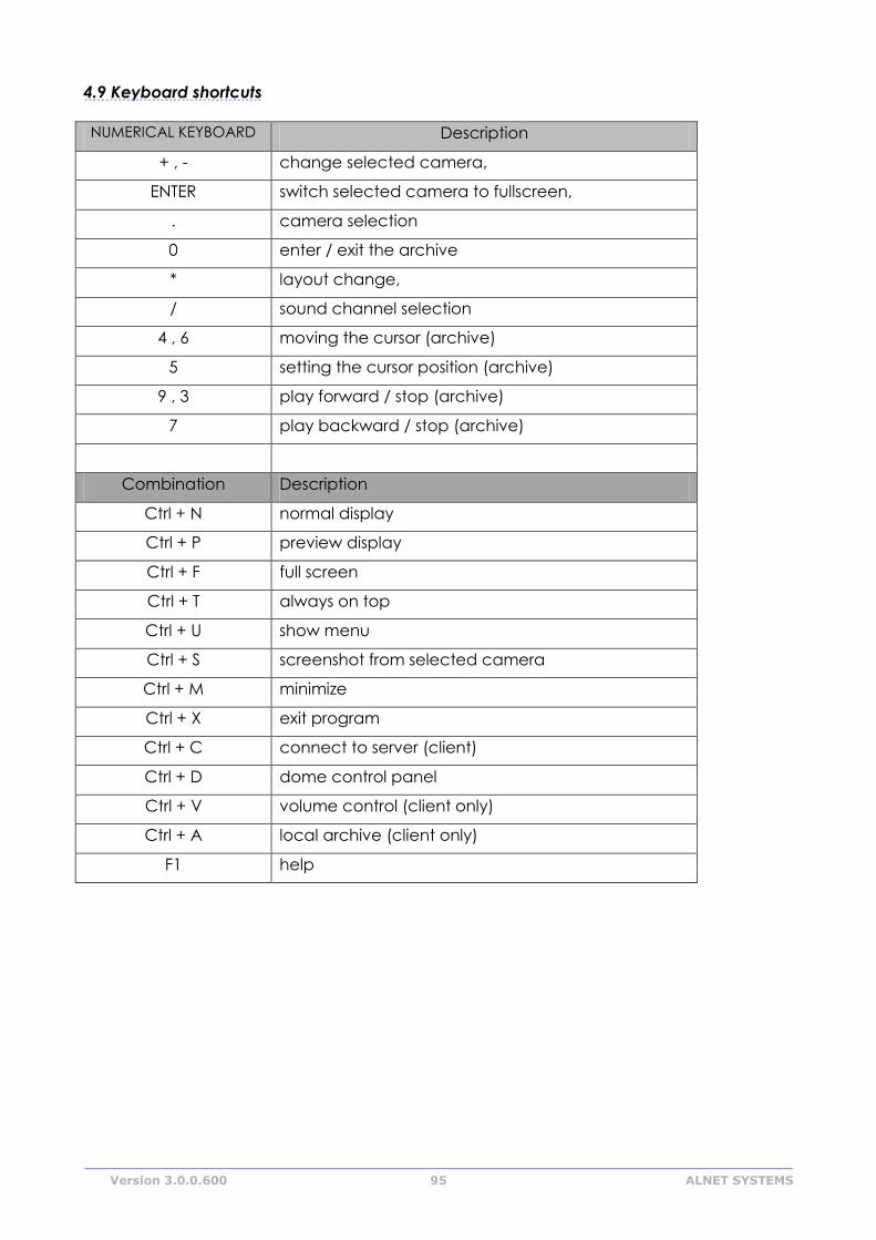
Version 3.0.0.600 95 ALNET SYSTEMS
4.9 Keyboard shortcuts
NUMERICAL KEYBOARD Description
+ , - change selected camera,
ENTER switch selected camera to fullscreen,
. camera selection
0 enter / exit the archive
* layout change,
/ sound channel selection
4 , 6 moving the cursor (archive)
5 setting the cursor position (archive)
9 , 3 play forward / stop (archive)
7 play backward / stop (archive)
Combination Description
Ctrl + N normal display
Ctrl + P preview display
Ctrl + F full screen
Ctrl + T always on top
Ctrl + U show menu
Ctrl + S screenshot from selected camera
Ctrl + M minimize
Ctrl + X exit program
Ctrl + C connect to server (client)
Ctrl + D dome control panel
Ctrl + V volume control (client only)
Ctrl + A local archive (client only)
F1 help