Embed Size (px)
Citation preview

User’sManual LN90
Interface Adapter
IM 01W03L01-01EN
IM 01W03L01-01EN 1st Edition

Toc-1
IM 01W03L01-01EN
Contents1. Introduction ............................................................................................... 1-1
1.1 Safe Use of This Product ................................................................................. 1-21.2 Warranty .............................................................................................................1-21.3 Copyright and Trademark Notice ....................................................................1-31.4 Control of Pollution Caused by the Product ..................................................1-3
2. Notes on Handling .................................................................................... 2-12.1 ChecktheModelNameandConfiguration .................................................... 2-22.2 Transport ............................................................................................................2-22.3 Storage ...............................................................................................................2-22.4 Selecting the Installation Location ................................................................. 2-22.5 EMC Conformity Standards .............................................................................2-32.6 Installation of an Explosion Protected Instrument ....................................... 2-3
2.6.1 IECEx Approval .................................................................................. 2-3
2.7 Preparation required for operation ................................................................. 2-5
3. Component Names .................................................................................. 3-14. Installation ................................................................................................. 4-1
4.1 Installation Environment ..................................................................................4-14.2 External Power Source ..................................................................................... 4-14.3 Grounding ..........................................................................................................4-14.4 Installation Example .........................................................................................4-24.5 Mounting ............................................................................................................4-3
4.5.1 Installation of FN110 .......................................................................... 4-3
4.5.2 Mounting of LN90 ............................................................................... 4-4
5. Wiring ......................................................................................................... 5-15.1 Notes on Wiring .................................................................................................5-15.2 Power Terminal Connection ............................................................................5-15.3 RS-485 Connector .............................................................................................5-25.4 COMM Terminal .................................................................................................5-3
6. Preparation to Use Attached Software................................................... 6-1
LN90 Interface Adapter
IM 01W03L01-01EN 1st Edition
1st Edition: July. 2017 (KP)All Rights Reserved, Copyright © 2017, Yokogawa Electric Corporation

Toc-2
IM 01W03L01-01EN
7. GeneralSpecifications ............................................................................ 7-17.1 StandardSpecifications ...................................................................................7-17.2 ModelandSuffixCodes ...................................................................................7-27.3 OptionalSpecification(ForExplosionProtectedType) ............................... 7-27.4 External Dimensions ........................................................................................7-37.5 Block Diagram ...................................................................................................7-5
Revision Information

<1. Introduction> 1-1
IM 01W03L01-01EN
1. IntroductionThis manual describes how to use LN90 Interface Adapter (hereafter simply referred to as LN90). LN90 is a RS-485 signal relay and power supply for the “Field Wireless Communication Module FN110” or other equipment. LN90 enables to connect PLC/RTU and FN110 with inter module code -R1 via a RS-485 interface. To ensure both safety and efficiency, read this manual and “User’s Manual of FN110 Field Wireless Communication Module” (IM 01W03B01-01EN) carefully before you operate LN90. For operation, maintenance and troubleshooting when connecting LN90 and FN110, refer to the “User’s Manual of FN110 Modbus Communication for PLC/RTU” (IM 01W03B01-21EN).
Table1.1 summarizes the related document list of this manual.Table 1.1 Related Document List
Title Document No.FN110 FieldWireless Communication Module General Specifications
GS 01W03B01-01EN
FN110 Field Wireless Communication Module User’s Manual IM 01W03B01-01EN
FN110 Modbus Communication for PLC/RTU User’s Manual IM 01W03B01-21EN
LN90 Interface Adapter General Specifications GS 01W03L01-01EN
Regarding This Manual
• This manual should be provided to the end user.
• This manual and the identification tag attached on packing box are essential parts of the product; keep them in a safe place for future reference.
• The contents of this manual are subject to change without prior notice.
• All rights reserved. No part of this manual may be reproduced in any form without Yokogawa’s written permission.
• Yokogawa makes no warranty of any kind with regard to this manual, including, but not limited to implied warranty of merchantability and fitness for a particular purpose.
• If any question arises or errors are found, or if any information is missing from this manual, please inform the nearest Yokogawa sales office.
• The specifications covered by this manual are limited to those for the standard type under the specified model number break-down and do not cover custom-made products. When products whose suffix code or optional codes contain code “Z” and an exclusive document is attached, please read it along with this manual.
• Please note that changes in the specifications, construction, or component parts of this product may not immediately be reflected in this manual at the time of change, provided that postponement of revisions will not cause difficulty to the user from a functional or performance standpoint.
• Yokogawa assumes no responsibilities for this product except as stated in the warranty.
• If the customer or any third party is harmed by the use of this product, Yokogawa assumes no responsibility for any such harm owing to any defects in the product which were not predictable, or for any indirect damages.
• The following safety symbols are used in this manual:
WARNING
Indicates a potentially hazardous situation which, if not avoided, could result in death or serious injury.
CAUTIONIndicates a potentially hazardous situation which, if not avoided, may result in minor or moderate injury or physical damage. It may also be used to alert against unsafe practices.
IMPORTANTIndicates that operating the hardware or software in this manner may damage it or lead to system failure.

<1. Introduction> 1-2
IM 01W03L01-01EN
NOTEDraws attention to information essential for understanding the operation and features.
1.1 Safe Use of This ProductThis product is designed to be used by a person with specialized knowledge. For the safety of the operator and to protect this product and the system, please be sure to follow this manual’s safety instructions when handling this product. If these instructions are not heeded, the protection provided by this product may be impaired. In this case, Yokogawa cannot guarantee that this product can be safely operated. Please pay special attention to the following points:
(a) Installation
• This product may only be installed by an engineer or technician who has an expert knowledge of this product. Operators are not allowed to carry out installation unless they meet this condition.
• With high process temperatures, care must be taken not to burn yourself by touching this product or its casing.
• All installation shall comply with local installation requirements and the local electrical code.
(b) Wiring
• This product must be installed by an engineer or technician who has an expert knowledge of this product. Operators are not permitted to carry out wiring unless they meet this condition.
(c) Maintenance
• Please carry out only the maintenance procedures described in this manual. If you require further assistance, please contact the nearest Yokogawa office.
• Care should be taken to prevent the build up of dust or other materials on the nameplate. To clean these surfaces, use a soft, dry cloth.
(d) ExplosionProtectedTypeInstrument
• Users of explosion protected instruments should refer first to section 2.6 (Installation of an Explosion Protected Instrument) of this manual.
• The use of this instrument is restricted to those who have received appropriate training in the device.
• Take care not to create sparks when accessing the instrument or peripheral devices in a hazardous location.
• Repair or modification to this instrument by customer will cause malfunction of explosion protect function and hazardous situation. If you need to repair or modification, please contact the nearest Yokogawa office.
(e) Modification
• Yokogawa will not be liable for malfunctions or damage resulting from any modification made to this product by the customer.
(f) AuthorizedRepresentativeintheEEA
• The Authorized Representative for this product in the EEA is: Yokogawa Europe B.V. Euroweg 2, 3825 HD Amersfoort, THE NETHERLANDS.
1.2 Warranty• The warranty shall cover the period noted on
the quotation presented to the purchaser at the time of purchase. Problems occurring during the warranty period shall basically be repaired free of change.
• If any problems are experienced with this product, the customer should contact the Yokogawa representative from which this product was purchased or the nearest Yokogawa office.
• If a problem arises with this product, please inform us of the nature of the problem and the circumstances under which it developed, including the model specification and serial number. Any diagrams, data and other information you can include in your communication will also be helpful.
• The party responsible for the cost of fixing the problem shall be determined by Yokogawa following an investigation conducted by Yokogawa.

<1. Introduction> 1-3
IM 01W03L01-01EN
The purchaser shall bear the responsibility for repair costs, even during the warranty period, if the malfunction is due to:
- Improper and/or inadequate maintenance by the purchaser.
- Malfunction or damage due to a failure to handle, use, or store this product in accordance with the design specifications.
- Use of the product in question in a location not conforming to the standards specified by Yokogawa, or due to improper maintenance of the installation location.
- Failure or damage due to modification or repair by any party except Yokogawa or an approved representative of Yokogawa.
- Malfunction or damage from improper relocation of the product in question after delivery.
- Reason of force majeure such as fires, earthquakes, storms/floods, thunder/ lightening, or other natural disasters, or disturbances, riots, warfare, or radioactive contamination.
1.3 Copyright and Trademark Notice
Copyright
All rights of the media and this manual are reserved. No part of the manual may be transferred, sold, distributed (including delivery via a commercial PC network or the like), or registered or recorded on video tapes or other media.
Trademarks
In this document, trademarks or registered trademarks are not marked with “™” or “®”. Product names and company names in this document are trademarks or registered trademarks of the respective companies.
1.4 Control of Pollution Caused by the ProductThis is an explanation for the product based on “Control of Pollution caused by Electronic Information Products” in the People’s Republic of China.
電子情報製品汚染制御管理弁法(中国版 RoHS)
产品中有害物质或元素的名称及含量
型号 部件名称
有害物质
铅
(Pb)
汞
(Hg)
镉
(Cd)
六价铬
(Cr(VI))
多溴联苯
(PBB)
多溴二苯
醚
(PBDE)
LN90
接口适配器
壳体 × ○ ○ ○ ○ ○
基板组件 × ○ ○ ○ ○ ○
电缆 × ○ ○ ○ ○ ○
○:表示该部件的所有均质材料中的有害物质的含量均在GB/T26572 标准中所规定的限量以下。
×:表示至少该部件的某些均质材料中的有害物质的含量均在GB/T26572 标准中所规定的限量以上。
环保使用期限:
20 该标识适用于 SJ /T11364 中所述,在中华人民共和国销售的电子电气产品的环保使用期限。
注)该年数为“环保使用期限”,并非产品的质量保证期。
<2. Notes on Handling> 2-1
IM 01W03L01-01EN
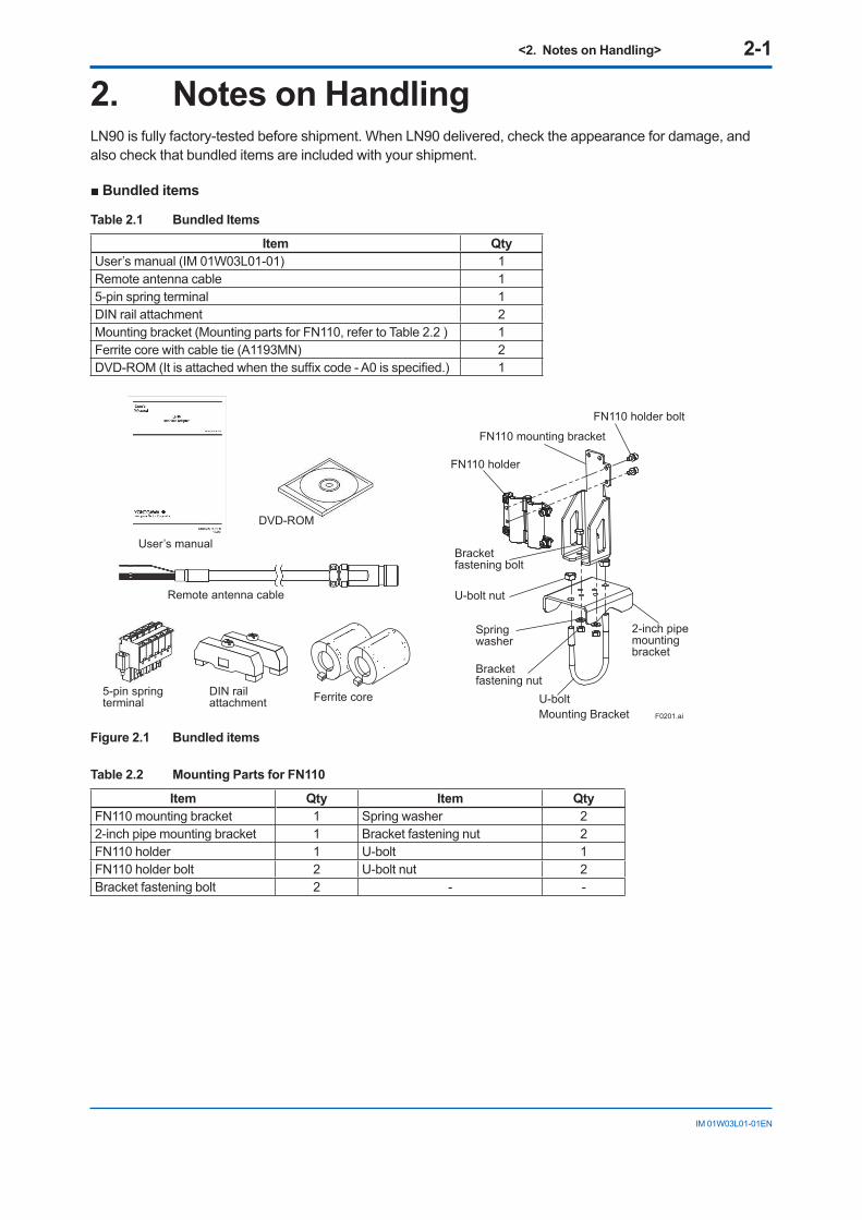
2. Notes on HandlingLN90 is fully factory-tested before shipment. When LN90 delivered, check the appearance for damage, and also check that bundled items are included with your shipment.
■Bundleditems
Table 2.1 Bundled Items
Item QtyUser’s manual (IM 01W03L01-01) 1Remote antenna cable 15-pin spring terminal 1DIN rail attachment 2Mounting bracket (Mounting parts for FN110, refer to Table 2.2 ) 1Ferrite core with cable tie (A1193MN) 2DVD-ROM (It is attached when the suffix code - A0 is specified.) 1
F0201.ai
FN110 holder bolt
U-bolt
FN110 holder
FN110 mounting bracket
U-bolt nut
Bracketfastening bolt
2-inch pipemountingbracket
Springwasher
Bracketfastening nut
User’s manual
5-pin springterminal
DIN railattachment Ferrite core
Remote antenna cable
DVD-ROM
Mounting Bracket
Figure2.1 Bundleditems
Table2.2 MountingPartsforFN110
Item Qty Item QtyFN110 mounting bracket 1 Spring washer 22-inch pipe mounting bracket 1 Bracket fastening nut 2FN110 holder 1 U-bolt 1FN110 holder bolt 2 U-bolt nut 2Bracket fastening bolt 2 - -

<2. Notes on Handling> 2-2
IM 01W03L01-01EN
2.1 Check the Model Name and Configuration
The model name and configuration are indicated on the nameplate. Verify that the configuration indicated in the “Model and Suffix Code” in subsection 7.2 is in compliance with the specifications written on the order sheet. A manual number omitting the language code at the end is printed on the nameplate.
F0202.ai
Figure2.2 Nameplate
MODEL: Specified model code.SUFFIX: Specified suffix code.STYLE: Style codeS/N: Serial numberDATE: Date of manufacture.SUPPLY: Rated inputOUTPUT: Rated outputTOKYO 180-8750 JAPAN: The manufacturer name and the address*1.
*1 “180-8750” is a zip code which represents the following address. 2-9-32 Nakacho, Musashino-shi, Tokyo Japan
2.2 TransportTo prevent damage while in transit, leave the product in the original shipping container until it reaches the installation site.
2.3 StorageWhen storing this product, observe the following precautions.
1. Chose a storage location that satisfies the following requirements.• A location that is not exposed to rain or water.• A location subject to a minimum of vibration
or impact.• The following temperature and humidity
range is recommended. Ordinary temperature and humidity (25°C, 65%) are preferable.
Temperature: -40 to 85°C Humidity : 5 to 95% RH
(no condensation)
2. If at all possible, store LN90 in factory- shipped condition, that is, in the original shipping container.
2.4 Selecting the Installation Location
Although this product is designed to operate in a harsh environment, to maintain stability and accuracy, the following is recommended.
Wireless Communication
NOTEThe installation location of this product must meet the following conditions:
• Install this product to be perpendicular to the ground.
• Install the FN110 at least 1.5 m above the ground or floor. Connect LN90 and FN110 with a remote antenna cable.
F0203.ai
1.5m
or m
ore
Remote antenna cable
to LN90
FN110
• Ensure that there are no obstacles such as walls or pipes within a 30 cm radius of the FN110.
• Confirm that each field wireless equipment can see the antenna of other devices which locate within its own communication range.

<2. Notes on Handling> 2-3
IM 01W03L01-01EN
Ambient Temperature
It is preferable to not to expose the instrument to extreme temperatures or temperature fluctuations. If LN90 is exposed to radiation heat a thermal protection system and appropriate ventilation is recommended.
Environmental Requirements
Do not install LN90 in a place that is exposed to corrosive atmospheric conditions. When using the instrument in a corrosive environment, ensure the location is well ventilated.
Impact and Vibration
It is recommended that the instrument be installed in a location that is subject to a minimum amount of impact and vibration.
Installation of Explosion Protected Products
An explosion-protected instruments is certified for installation in a hazardous area containing specific gas types. See subsection 2.6 “Installation of an Explosion-Protected Instruments”.
2.5 EMC Conformity Standards
CAUTIONThis instrument is a Class A product, and it is designed for use in the industrial environment. Please use this instrument in the industrial environment only.
IMPORTANTIn order to comply with the EMC standard, mount bundled two ferrite cores “A1193MN” to external power source cable of LN90 side.
2.6 Installation of an Explosion Protected Instrument
2.6.1 IECEx ApprovalCaution for IECEx Type n Certification
(1) TechnicalDataNote 1. Model LN90 Interface Adapter with optional code /SN27
is applicable for use in hazardous area.
• Certificate No: IECEx PRE 17.0019X• Applicable Standards: IEC 60079-0: 2011, IEC 60079-15: 2010• Type of Protection: nA (non-sparking low power equipment)• Marking: Ex nA IIC T4 Gc• Ambient Temperature: -40 to 70°C (altitude : up to 3000 m)• Rated Input: 12 VDC, 40 mA or 24 VDC, 20 mA• Rated Outputt: 3.5 V, 60 mA
(2) SpecificConditionofUse
• Equipment must be installed so that pollution degree 2 in accordance with IEC 60664-1 is maintained inside the enclosure.
• Equipment shall be installed in an enclosure that complies with requirements of the standard IEC60079-15, and provide a degree of ingress protection not less than IP54. Alternatively it shall be installed in an Ex e enclosure.

<2. Notes on Handling> 2-4
IM 01W03L01-01EN
(3) Installation
WARNING
WHEN AN EXPLOSIVE ATMOSPHERE IS PRESENT, DO NOT OPEN THE CABINET WHILE THE EQUIPMENT ARE ENERGIZED. DO NOT SEPARATE THE CONNECTIONS WHEN ENERGIZED.
• The equipment must be installed in accordance with IEC 60079-14 and relevant local codes.
• To connect external wires, follow the instructions below.
RS-485 connector: Make sure that the connection is effectively
secured with the latch of the connector.POWER terminal: The conductors of the cable must be
equipped with crimp terminals. Recommended torque value of tightening screws: 1.2 Nm
COMM terminal: The COMM terminal consists of a 5-pin
plug and a socket. A remote antenna cable equipped with ferrule must be used. The conductors of the cable must be inserted into the plug according to the colors:
FG – Uncolored SG – Black PS – Red DTP – Blue DTN – White Make sure that the conductors are
effectively secured to the plug. The plug must be secured to the socket with the screws on the flange.
• Care must be taken to avoid multi-point earthing since the equipment is not galvanically isolated from the power supply.
(4)Operation
WARNING
Take care not to generate mechanical sparking when access to the instrument and peripheral devices in hazardous area.
(5)MaintenanceandRepair
WARNING
• Inspections and maintenance of the equipment and installations shall be carried out only by qualified personnel and in accordance with EN 60079-17.
• Repair, overhaul, reclamation of the equipment shall be carried out only by qualified personnel and in accordance with EN 60079-19.
• Repairs of the equipment shall be carried out only by trained, experienced, skilled, knowledgeable and/or supervised personnel, or by the service engineers recognized by Yokogawa. Otherwise, the type of protection may be invalidated.
• Modifications shall not be made to the equipment which are operated in hazardous areas.
• When opening the cabinet, the enclosure should be dry and clean to prevent the ingress of water and dust.
(6) NamePlate
F0204.ai
MODEL: Specified model code.SUFFIX: Specified suffix code.STYLE: Style codeS/N: Serial numberDATE: Date of manufacture.SUPPLY: Rated inputOUTPUT: Rated outputTOKYO 180-8750 JAPAN: The manufacturer name and the address*1.*1: “180-8750” is a postal code which represents the following
address. 2-9-32 Nakacho, Musashino-shi, Tokyo Japan

<2. Notes on Handling> 2-5
IM 01W03L01-01EN
2.7 Preparation required for operation
The work required to use LN90 is as follows.It also shows the main references in this document.
Check the appearance and bundled items
Check the appearance for damage, and also check that bundled items are included with your shipment. For more details, refer to chapter 2 “Notes on Handling”.
InstallLN90,FN110andhostsystem
Install LN90 and wire the other equipment. For more details, refer to chapter 4 “Installation” and chapter 5 “Wiring”. For FN110 installation and wiring, refer to “FN110 Field Wireless Communication Module (IM 01W03B01-01EN).For instructions on engineering of FN110, refer to “User’s Manual of FN110 Modbus Communication for PLC/RTU”(IM 01W03B01-21EN).

<3. Component Names> 3-1
IM 01W03D01-01EN
3. Component Names
8 7 6 5 4 3 2 1
WhiteBlueRedBlackUncolored
Remote antenna cable
1Transmit/Receive Data positiveDATA+
2Transmit/Receive Data negativeDATA-
3 N/C4 N/C5 N/C6 N/C7 N/C8 Signal GroundGND
Pin SignalName
FG SG PS DTP
DTN
+ -
POWER Terminal with cover
COMM Terminal
FN110
External power source
RS-485 Connector(RJ-45)
F0301.ai
No ConnectionNo Connection
No ConnectionNo ConnectionNo Connection

<4. Installation> 4-1
IM 01W03L01-01EN
4. Installation4.1 Installation Environment• Before installing LN90 , read the cautionary
notes in subsection 2.4 “Selecting the Installation Location”.
• When installing this product outdoors, accommodate it in a metal cabinet with appropriate dustproof and waterproof performance.
• When pulling out the wiring cable from the cabinet, attach a proper cable gland to the cabinet withdrawal port and take waterproof measures.
• For additional information on the ambient conditions allowed at the installation location, refer to subsection 7.1 “Standard Specifications”.
WARNING
• Take care not to let water enter the instrument or to allow it to get wet. Failure to observe this may result in fire, electric shock or breakdown.
• Do not insert metal bars or such like into gaps on the instrument. Doing so may result in fire, electric shock or accident.
IMPORTANT• Avoid exposing LN90 to direct sunlight.• Prevent condensation under any
circumstance.• The dust level of the room should not exceed
0.3 mg/m3. Under any circumstance, avoid iron flakes, carbon particles, or any other type of dust that are conductive.
• Avoid existence of corrosive gases such as hydrogen sulfide, sulfurous acid gas, chlorine, and ammonia.
4.2 External Power SourceRequired external power source specification;
• Output voltage: 12 V DC or 24 V DC
• Output capacity: 1 W or more
WARNING
• LN90 does not have a power switch. For maintenance and safety, it is recommend installing a power switch close to LN90 and clearly indicating the OFF position of the switch.
• The overcurrent protection circuit of the external power source, it is recommended to use the automatic-recover type with the reverse L-shaped.
IMPORTANTWhen using the commercial power, the EN60950 certified external power source is necessary to comply with safety standards.
4.3 GroundingGround the ground terminal of LN90 according to the standards of each country and region.For details of ground wiring, refer to 5.2 Power Terminal Connection.
WARNING
• Ground host system and LN90 to the same point to equalize an electrical potential.
• Select the host system with the isolated RS-485 port, when the host system and LN90 are installed in different place.

<4. Installation> 4-2
IM 01W03L01-01EN
4.4 Installation ExampleAn example of installing RTU, LN90 and FN110 is shown below. This figure is an example of putting RTU and LN90 in the same cabinet. In this example, LN90 and RTU ground the equipotential bonding bar to equalize an electrical potential. Also, the power supply of LN90 and RTU is shared.
FN110
Equipotential bonding bar
Cabinet
PLC/RTU
Remoteantenna cable
LN90
External power source
Ferrite cores
RS-485 cable
External power source cables
Grounding cable
F0401.ai
Figure4.1 InstallationExample

<4. Installation> 4-3
IM 01W03L01-01EN
4.5 Mounting
4.5.1 InstallationofFN110
LocationofFN110
Mount FN110 at the proper location according to the wireless environment described in subsection 2.4 “Selecting the Installation Location”. The mounting to the pipe such as 50 A (2-inch) pipe needs to secure the enough durability to endure a strong wind, vibration and so on. FN110 must be mounted vertically.
FixingofFN110
Fix the FN110 on a 50 A (2-inch) pipe with the mounting bracket provided as the remote antenna cable option.• To install FN110 with mounting bracket, follow
the procedure below.
1 Assemble the mounting bracket and fix it on a 50 A (2-inch) pipe.
2 Connect the remote antenna cable to FN110.3 Protect the connection as necessary.4 Fix FN110 to the mounting bracket.
CAUTION• Turn off a power to LN90 before installing
FN110.• When installing FN110, fix the FN110 by
tightening the lock nut. Screwing by holding the FN110 housing may cause failure such as cable disconnection. The same manner should be taken when removing the FN110.
FN110 holder
FN110 mounting bracket
FN110 holder bolt
U-bolt
Bracketfastening nut
Bracket fastening bolt
Spring washer
U-bolt nut
FN110
Remote antenna cable
2-inch pipe mounting bracket
2-inch pipeF0402.ai
Figure4.2 HorizontalPipeMountingofFN110
2-inch pipe Bracketfastening nut Spring washer
U-bolt nut FN110 mounting bracket
FN110 holder bolt
FN110
Remote antenna cable
FN110 holder
Bracket fastening bolt
2-inch pipe mounting bracket
U-bolt
F0403.ai
Figure4.3 VerticalPipeMountingofFN110
<4. Installation> 4-4
IM 01W03L01-01EN
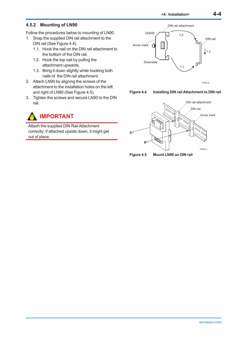
4.5.2 Mounting of LN90Follow the procedures below to mounting of LN90.1. Snap the supplied DIN rail attachment to the
DIN rail (See Figure 4.4). 1.1. Hook the nail on the DIN rail attachment to
the bottom of the DIN rail. 1.2. Hook the top nail by pulling the
attachment upwards. 1.3. Bring it down slightly while hooking both
nails of the DIN rail attachment.2. Attach LN90 by aligning the screws of the
attachment to the installation holes on the left and right of LN90 (See Figure 4.5).
3. Tighten the screws and secure LN90 to the DIN rail.
IMPORTANTAttach the supplied DIN Rail Attachment correctly; if attached upside down, it might get out of place.
1.2
1.1
DIN rail
1.3
DIN rail attachment
Upside
Downside
F0404.ai
Arrow mark
Figure4.4 InstallingDINrailAttachmenttoDINrail
DIN rail attachment
DIN rail
Arrow mark
F0405.ai
Figure4.5 MountLN90onDINrail

<5. Wiring> 5-1
IM 01W03L01-01EN
5. Wiring5.1 Notes on WiringLN90 has a 3-pole M4 terminal with terminal cover for power supply, RJ-45 connecter for RS-485 communication, and a 5-pin connecter with a spring terminal and its socket on the body for communication to the field wireless communication module. The spring terminal base is secured by two screws at both ends. To connect external wires, follow the instructions below.
F0501.ai
External power source cable
Grounding cable
Ferrite core(A1193MN)
COMM terminal
+-
RS-485 cable
Remote antenna cable
Screwable flange to secure the plug to the socket.
POWER terminal
RS-485 connector
Figure5.1 WiringofLN90
NOTE• When wiring where the ambient temperature
is high or low, use the cable or wire that appropriate to that place.
• When the maximum operating temperature is more than 60°C, use the cable of 85°C or higher temperature rating.
• After wiring, properly fix the wiring so that no stress is applied to the terminal and connector.
5.2 Power Terminal Connection
Applicable Cables
Insulated cables for industrial equipment such as;
• 600 V polyvinyl chloride insulated wires (IV); JIS C3307
• Polyvinyl chloride insulated wires for electrical apparatus (KIV); JIS C3316
• 600 V grade heat-resistant polyvinyl chloride insulated wires (HIV); JIS C3317
• Heatproof vinyl insulated wires VW-1 (UL1015/ UL1007) Wire size
• Core: AWG14 to 13 (2 mm2 to 2.6 mm2) Termination
• A ring terminal for M4 terminals with an insulation covers
Wiresize
• For external power source: 0.5 mm2 to 2.0 mm2 (AWG 20 to 14)
• For grounding: 2.0 mm2 to 2.6 mm2 (AWG14 to 13)
IMPORTANT• LN90 does not have a power switch. It
is recommended that a power switch be installed near LN90 and to clearly display the OFF position of the switch, for maintenance and safety requirements.
• The overcurrent protection circuit of the external power source, it is recommended to use the automatic-recover type with the reverse L-shaped.

<5. Wiring> 5-2
IM 01W03L01-01EN
8 7 6 5 4 3 2 1
1Transmit/Receive Data positiveDATA+
2Transmit/Receive Data negativeDATA-
3 N/C4 N/C5 N/C6 N/C7 N/C8 Signal GroundGND
Pin SignalName
RS-485 Connector(RJ-45)
F0504.ai
No ConnectionNo Connection
No ConnectionNo ConnectionNo Connection
Figure5.4 PinAssignmentoftheRS-485Connector
When connecting to the RS-485 port of Yokogawa's FCN-RTU (CPU Module NFCP 050), use a straight cable.
Cable Connection
Connect the RS-485 connector of the host system and the RS-485 connector of the LN90 with the RJ-45 plug. Make sure that the connection is effectively secured with the latch of the connector.
NOTEThe GND of the RS-485 connector is connected to the ground potential inside LN90.
Installation of ferrite cores
After wiring the power terminal, install two ferrite cores (A1193MN) to the external power source cable according to the Figure 5.2.
Cable tieCable tie
Ferrite core(A1193MN)
Externalpower source cable
Externalpower source cable
Ferrite core(A1193MN) F0502.ai
Figure5.2 InstallationofFerriteCores
IMPORTANT• Do not apply mechanical shocks such as
dropping to the ferrite core.• Do not perform installation work at ambient
temperature below 0°C.
Grounding
Appropriate grounding is necessary for the stable operation of LN90. Connect the grounding cable from the ground at POWER terminal to the ground.
F0503.ai
Ground
POWER terminal
RS-485 connector
Figure5.3 ThegroundatPOWERterminal
5.3 RS-485 Connector
Applicable Cables
Prepare an RJ-45 plug that matches the pin assignment of the RS-485 connector shown in Figure 5.4. Using Category 5 UTP cable or more that is commercially available is recommended.
<5. Wiring> 5-3
IM 01W03L01-01EN
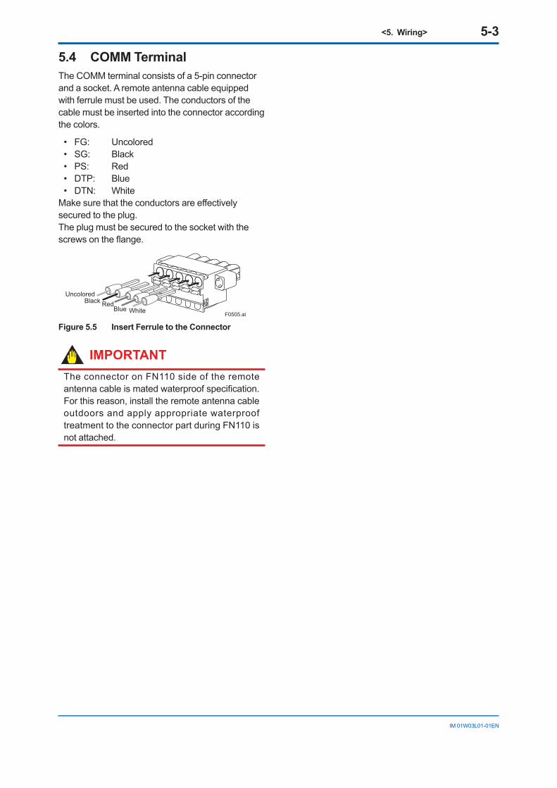
5.4 COMM TerminalThe COMM terminal consists of a 5-pin connector and a socket. A remote antenna cable equipped with ferrule must be used. The conductors of the cable must be inserted into the connector according the colors.
• FG: Uncolored• SG: Black• PS: Red• DTP: Blue• DTN: White
Make sure that the conductors are effectively secured to the plug. The plug must be secured to the socket with the screws on the flange.
UncoloredBlack Red
Blue White F0505.ai
Figure5.5 InsertFerruletotheConnector
IMPORTANTThe connector on FN110 side of the remote antenna cable is mated waterproof specification. For this reason, install the remote antenna cable outdoors and apply appropriate waterproof treatment to the connector part during FN110 is not attached.

<6. Preparation to Use Attached Software> 6-1
IM 01W03L01-01EN
6. Preparation to Use Attached Software
How to Use Online Manual
It is necessary to install Adobe Acrobat Reader to read the instruction manual (FN110 Modbus Communication for PLC/RTU: IM 01W03B01-21EN).
Adobe Reader can be downloaded from the web site of Adobe Systems Incorporated.
Reading Online Manual
The online manual is stored in the attached DVD-ROM. Open the file by Adobe Reader to read the manual.
DVD-ROM Drive: \Document\en\IM01W03B01-21EN.pdf
Notes on Attached Software
• Yokogawa assumes no responsibilities for this software except as stated in the warranty.
• This software is used with this product exclusively. This software can be viewed and operated in the computer which connects with this product.
To use attached software, the following environment is required.
Table6.1 Software operating environment
Item VersionOS*1*2*3 Windows 7
Home PremiumSP1 or later
Windows 7 Professional
SP1 or later
Windows 10 Home
November Update version 1511 build or later
Windows 10 Pro November Update version 1511 build or later
FieldMate R3.02 or later
*1: Both of 32 bit and 64 bit edition and Japanese and English language are supported
*2: For 64 bit OS, WOW64 (Windows 32-bit On Windows 64-bit) can be performed.
*3: Microsoft .NET Framework 4.6.1 is required.
The details of attached DVD-ROM, refer to the Readme_en.txt
DVD-ROM Drive: \Readme_en.txt
Open Source Software
ISA100 Wireless Gateway Assistant does not use the open source software.

<7.GeneralSpecifications> 7-1
IM 01W03L01-01EN
7. GeneralSpecificationsRefer to GS 01 W03L01-01EN for the latest information.
7.1 StandardSpecifications
POWERSUPPLYSPECIFICATIONS
Input voltage range: 10 to 30 V DCRated input: 12 V DC 40 mA or 24 V DC 20 mARated Output: 3.5 V DC 60 mA
PERFORMANCESPECIFICATIONS
Digital Communication:Communication Mode: RS-485 Half-duplex
(2-wire type)Communication Speed: Max 38400 bpsCommunication Distance: Max 20 m*1*2
*1: Total length of RTU to FN110.*2: 3 m dedicated cable is bundled to connect FN110.
INSTALLATION ENVIRONMENT
Ambient Temperature Limits:Operating: –40 to 70°C (attitude up to 3000 m)Storage: –40 to 85°C
Ambient Humidity Limits:Operating: 5 to 95%RH (non-condensation)Storage: 5 to 95%RH (non-condensation)
Noise Resistance:Electric Field : 3 V/m or less (80 to 1000 MHz)Electrostatic Discharges: 4 kV or less (contact
discharge), 8 kV or less(aerial discharge)
Installation location:Indoors
Vibration Resistance:0.15 mm P-P (5 to 58 Hz) , 1 G (58 to 150 Hz)
Shock Resistance:15 G 11 ms
REGULATORY COMPLIANCE STATEMENTS
CE Conformity:EMC Directive:
EN61326-1 Class A Table 2, EN55011 Class A*1
RoHS Directive: EN50581
Other Normative Standards: Safety: EN61010-1 (Indoor use)
PHYSICALSPECIFICATIONS
Housing Material:Aluminum alloy plate
External Dimension:95 x 83 x 25.4 mm (not include projection)
Weight:Approx. 200 g
Mounting:DIN RAIL Mounting
SOFTWARESPECIFICATIONS
ISA100 Wireless Gateway Assistant:The installer of ISA100 Wireless Gateway Assistant is included in the DVD-ROM which is bundled with this product. This software does not use for FN110 configuration normally. When detailed configuration is necessary, install this software.
Software License:1 License
Language:Software(GUI): EnglishManual: English
Hardware Operating Environment:
Item Recommended System Requirements
Processor Intel Core i5-2520M or equivalent, or higher
Memory 2 GB or moreHard Disk 8 GB or moreDisplay 1024×768 or better resolution
Recommended OS compatibleCommunication Device
USB to Isolated RS-485 adapter
Software Operating Environment:Item Version
OS*1*2*3 Windows 7 Home Premium
SP1 or later
Windows 7 Professional
SP1 or later
Windows 10 Home
November Update version 1511 build or later
Windows 10 Pro November Update version 1511 build or later
FieldMate R3.02 or later
*1: Both of 32 bit and 64 bit edition and Japanese and English language are supported
*2: For 64 bit OS, WOW64 (Windows 32-bit On Windows 64-bit) can be performed.
*3: Microsoft .NET Framework 4.6.1 is required.

<7. General Specifications> 7-2
IM 01W03L01-01EN
7.2 ModelandSuffixCodesModel SuffixCodes Description
LN90 .... Interface Adapter
GeneralSpecifications
.... -A Always A
Software Media0 Provided with DVD-ROM1 None
Option codes /Optional specifications
7.3 OptionalSpecification(ForExplosionProtectedType)Item Description Code
IECEx IECEx Type n ApprovalApplicable Standards: IEC 60079-0:2011, IEC 60079-15:2010Certificate: IECEx PRE 17.0019X*¹Ex nA IIC T4 GcAmb. Temp. (Tamb): –40 to 70°C (–40 to 158°F)
SN27
*1: Symbol ‘X’ denotes the following specific conditions of use: · Equipment must be installed so that pollution degree 2 in accordance with IEC 60664-1 is maintained inside the enclosure · Equipment shall be installed in an enclosure that complies with requirements of the standard IEC60079-15 such as metal cabinets
with locks and keys and provide a degree of ingress protection not less than IP54. Alternatively it shall be installed in an Ex e enclosure.

<7.GeneralSpecifications> 7-3
IM 01W03L01-01EN
7.4 External Dimensions
BodyUnit: mm (approx. inch)
25.4 (1.00)
41.5
(1.6
3)
12 (0.47)95 (3.74)77 (3.03)
83 (3
.27)
86.5 (3.41)(0.61)15.5
COMM terminal
Power terminal with coverRS-485 connector
DIN rail mounting bracket
F0701.ai
Remote antenna cableUnit: mm (approx. inch)
Wire Color SignalUncolored Frame groundBlack Signal groundRed Power supplyBlue Transmit/receive data positiveWhite Transmit/receive data negative
Ø8.7±0.2(0.34±0.01)
3000
(118
.11)
50 (1
.97)
F0702.ai
FN110 connector
LN90 connection wire

<7. General Specifications> 7-4
IM 01W03L01-01EN
FN110MountingBracket
● 2-inchpipemounting(forhorizontalpiping)
Unit: mm (approx. inch)
191
(7.5
2)
FN110
Remoteantenna cable
Mounting bracket
2-inch pipe
88 (3.46)
80 (3.15)
40 (1.57)
148
(5.8
3)
47 (1
.85)
56 (2.20)
20 (0.79)
93 (3.66)F0703.ai
● 2-inchpipemounting(forverticalpiping)
93 (3.66)20 (0.79)
56 (2.20)
Remoteantenna cable
FN110
209 (8.23)
184 (7.24)
Mounting bracket
2-inch pipe
80 (3
.15)
Unit: mm (approx. inch)
F0704.ai
22 (0.87)

<7.GeneralSpecifications> 7-5
IM 01W03L01-01EN
7.5 Block Diagram
COMMTerminal+
–
PS
SG
DTN
FG
DTPDATA+
DATA-
GND
RS-485 Connector
SG-FGtie-upDC/DC
LN90
DC/DC
POWER Terminal
3.5 V 60 mA
FN110
12 V DC or 24 V DC
Ground
RS-485 Port of RTU
F0705.ai

i
IM 01W03L01-01EN
Revision InformationTitle : LN90 Interface Adapter Manual No. : IM 01W03L01-01EN
Edition Date Page Revised item1st July 2017 ― New Publication