Embed Size (px)
Citation preview

MILLPWRG2
User’s Manual
8/2017
2
Co
ntr
ols
of
the
MIL
LP
WR
G2
Controls of the MILLPWRG2
Keys on console
Motion control keys
Data entry keys
Function keys
Numerical keys
Axis keys
Soft keys
Key Function
GO key (e.g. run a program).
STOP key (duel function: press once to pause, press twice to stop a program).
Key Function
CANCEL key cancels operation, i.e. form.
CLEAR key clears selections, i.e. values in a field, a program step.
USE key completes operation, i.e. data entered in a form.
ENTER key completes selection, i.e. values entered in a field.
Key Function
ABS/INCR key toggles between Absolute or Incremental positioning.
DRO/PGM key toggles between the DRO display or Program mode display.
VIEW key opens a form to configure graphics parameters; i.e. 2D or 3D.
INFO key opens on-screen manual.
MM key toggles between INCH or MM mode.
SETUP key opens configuration menu.
Key Function
ZERO key.
ONE key.
TWO key.
THREE key.
FOUR key.
FIVE key.
SIX key.
SEVEN key.
EIGHT key.
NINE key.
DECIMAL key.
PLUS / MINUS key.
Key Function
AXIS keys open the datum, or preset form.
Key Function
SOFT KEYS performs the function directly above it.

ACU-RITE MILLPWRG2 3
Co
ntr
ols
of
the
MIL
LP
WR
G2Move table and navigation keys
Calculator function keys
Potentiometer for feed rate override
Milling function keys
Peripherals supported:
USB memory devices; e.g. a memory stick.Networking, USB pointing devices; e.g. a mouse, USB
keyboard.
Key Function
LEFT ARROW key will move the table or display cursor depending on the function selected.
RIGHT ARROW key will move the table or display cursor depending on the function selected.
UP ARROW key will move the table or display cursor depending on the function selected.
DOWN ARROW key will move the table or display cursor depending on the function selected.
Key Function
CALC key opens the calculator.
PLUS key.
MINUS key.
MULTIPLIER key
DIVIDE key.
Feed rate override
Key Function
TOOL key opens the SET TOOL dialogue.
RECT key opens the Rectangle milling popup menu.
CIRCLE key opens the Circle milling popup menu.
HOLES key opens the Hole pattern popup menu.
POS key opens the POSITION / DRILL data input dialogue.
LINE key opens the MILL LINE data input dialogue.
ARC key opens the MILL ARC data input dialogue.
BLEND key opens the BLEND \ CHAMFER data input dialogue.
BLANK key opens the user defined milling function data input form.

4
Co
ntr
ols
of
the
MIL
LP
WR
G2

ACU-RITE MILLPWRG2 5
Ma
nu
al
Info
rma
tio
nManual Information
Message symbols
Attention!
This symbol indicates that there is one or more of the following risks when using the described function
Danger to work pieceDanger to fixturesDanger to toolDanger to machineDanger to operators
Damage!
This symbol indicates that there is risk of MILLPWRG2 damage, or electrical shock if instructions are not adhered to.
Different from machine to machine!
This symbol indicates that instructions may apply differently from one type of machine to another type of machine.
Refer to another Manual!
This symbol indicates that information required is located elsewhere (i.e. Machines Owner Manual).
Advice!
This symbol indicates that an Advice tip is being provided. Important, and/or additional information about the function described.
6
Ma
nu
al
Info
rma
tio
n Fonts used in this manual
Reference to the: Console HARD KEYS.
Reference to the: Display Screen Soft Keys.
Reference to the: Display Screen dialogues.
Reference to the: Display Screen Fields.
Changes (errors)
HEIDENHAIN CORPORATION is continuously striving to improve. Please help HEIDENHAIN CORPORATION by sending your request to the following e-mail address: [email protected]
Visit www.ACU-RITE.com for latest version of this manual.
Model, software and features
This manual describes functions and features provided by MILLPWRG2 as of the following NC software number.
The machine tool builder may not allow some of the functions described in this manual, therefore they may not be among the features provided by the MILLPWRG2 on your machine tool.
The machine tool builder representative can assist with becoming familiar with the features of the machine.
Many machine manufacturers, as well as HEIDENHAIN Corp., offer programming courses for the MILLPWRG2. We recommend these courses as an effective way of improving your programming skill and sharing information and ideas with other MILLPWRG2 users.
Intended place of operation
The MILLPWRG2 is intended for use primarily in industrially-zoned areas. Refer to the respective installation manual for additional information.
Console model NC software number
ACU-RITE MILLPWRG2 Software 751005-04

ACU-RITE MILLPWRG2 7
Ma
nu
al
Info
rma
tio
nNew functions of software
751005-01-01
Zero Incremental was added to Chapter 2.2.
751005-02-00
Geometry/RPM Calculator functions added to Chapter 9.2. Support for Auxiliary Machine Interface (AMI) added to Chapter 8.2
Basic editing of g-code programs added to Chapter 6.2 Tool step supports plunge angle, added to Chapter 4.1. Pockets can be ramped into at an angle or plunged into.
751005-03-00
Pilot Drilling has been added to programing functions in Chapter 8.2.Display resolution can be selected for metric and inch; see
Chapter 10.1Drill markers corresponding to the tool size are now shown in 2D
and 3D line views for MILLPWRG2 programs; see Chapter 5.1.G-code programs now support the Block Form feature;
see Chapter 6.2.Reference points are now shown graphically; see Chapter 5.1.
751005-04-00
Advanced custom pocket machining has been added; see Chapter 8.2.
Step Form Validation has been added; see page 104.Radial Slot Cycle has been added; see Chapter 8.1. Parameter for reduced feedrate on full pocket cuts has been added
to Job Setup; see Chapter 10.1.
751005-04-05
Redraw soft key has been added to View Setup Dialogue; see Chapter 5.1.
Graphics Only soft key has been added to Run Options; see Chapter 5.1.
751005-05-00
Redraw soft key has been added to View Setup Dialogue; see Chapter 5.1.
Graphics Only soft key has been added to Run Options; see Chapter 5.1.
Updated instructions for View hard key Operation; see Chapter 5.1.Description of soft keys in View setup has been added; see Chapter
5.1.Graphics Only soft key in Testing a MILLPWRG2 program has been
added; see Chapter 6.1. Skipping Steps in a Program has been added; see Chapter 6.1.Rectangular and Circular contours for use as islands has been
added; see Chapter 8.1. Fine Rough field has been added to Rough Milling; see Chapter 8.2.

8
Ma
nu
al
Info
rma
tio
n 751005-06-00
Goto Tool Number feature was added to the Tool Table; see Chapter 4.1.
Recycle Bin feature was added to the Program Functions area; see Chapter 5.1.
New simulation graphics features and View Setup soft keys were added; see Chapter 5.1.
Rectangle Face step now allows additional methods of definition; see Chapter 8.1.
Radial Slot step now allows additional methods of definition; see Chapter 8.1.
Engrave Line step now allows additional methods of definition; see Chapter 8.2.
Engrave Arc step now allows additional methods of definition; see Chapter 8.2.

ACU-RITE MILLPWRG2 9
Ma
nu
al
Info
rma
tio
nChanged functions of software
751005-01-01
Blend/Chamfer information input (see page 166) has been redefined.
Preset Moves information input (see page 49) has been redefined.Display:Peck\Pass (see page 229) has a note added that the limit of
pecks or passes is 9999.
751005-01-02
The Off-line software described (see page 236) now requires the purchase of a USB Protection Module for operation.
Custom Pocket: The tool path for custom pockets and islands, described (see page 196) has changed to use the programmed cutting convention.
751005-01-03
A message box warning that the software travel limits are not established prior to homing has been added (see page 25).
751005-01-04
Part Graphics: The show tool path and show step number options were removed from the graphics view (see page 80).
Probing examples were added (see page 107).
751005-02-00
Rectangular milling functions can now be established from its center position (see page 171).
Max feedrate override can now be up to 200%, see page 227.
Support for angles in DMS (see page 46).Change steps allows changing of drill types (see page 194). Tool steps can now be programed using a tool number (see page
71). Program functions enhancements (see page 80). Explode step function on Engrave Arc and Engrave Line steps (see
page 192). Improved graphics performance (see page 79).
751005-03-00
Teach Position and Probe soft key are now always available together (see page 56).
Show Contour is now available in 3D line view in addition to 2D line view (see page 87).
Forward or Reverse is now available for finish passes (see page 169).
751005-04-00
The Service files section has been updated; see Chapter 10.1. Software update procedure has been updated; see Chapter 10.1. Shutdown / Restart procedure has changed (see page 26). VIEW hard key description has been updated; see Chapter 5.1.

10
Ma
nu
al
Info
rma
tio
n Aux step now allows user specified continuity; see page 207. The Contour step is now part of the Position/Milling soft key; see
page 163.
751005-04-06
When importing DXF file, Position / Drill steps will have the job option set to Drill.
751005-05-02
When importing a DXF file, Position / Drill steps will have the job option set to Drill.
VIEW hard key description has been updated; see Chapter 5.1.
751005-06-00
VIEW hard key description has been updated; see Chapter 5.1.Bottom Finish and Side Finish field definitions have changed (can no
longer be defined as having no value); see Chapter 8.1.W-Axis motion allowance tolerance is now user-configurable; see
Chapter 1.2. Section 13 was updated to describe both the new Virtual Machine
Simulator software for 751005-06-00 (Release 6 or R6) and newer software versions (see Chapter 13.2), as well as the previously available Windows Off-Line Software for versions prior to R6 (see Chapter 13.3).

ACU-RITE MILLPWRG2 11
MIL
LP
WR
G2 A
cce
ss C
od
e
MILLPWRG2 Access Code
Access code
Access to machine parameter operations
The access code must be entered before the installation setup parameters can be accessed or changed.
Press the SETUP key to enter the Job Setup dialogue.
Press the Install Setup soft key, and enter the access code.
Attention!
The parameter access code is 8891
Attention!
To prevent setup parameters from being changed, remove this page from the manual after initial system setup. Retain this information in a safe place for future use.

12
MIL
LP
WR
G2 A
cce
ss C
od
e

ACU-RITE MILLPWRG2 13
Table of Contents
Controls of the MILLPWRG2
Keys on console....................................................................................................... 2Motion control keys ............................................................................................ 2Data entry keys ................................................................................................... 2Function keys...................................................................................................... 2Numerical keys ................................................................................................... 2Axis keys............................................................................................................. 2Soft keys ............................................................................................................. 2
Move table and navigation keys .............................................................................. 3Calculator function keys........................................................................................... 3Potentiometer for feed rate override ....................................................................... 3Milling function keys................................................................................................ 3Peripherals supported: ............................................................................................. 3
Manual Information
Message symbols.................................................................................................... 5Fonts used in this manual ................................................................................... 6
Model, software and features ................................................................................. 6Intended place of operation ................................................................................ 6
New functions of software ...................................................................................... 7751005-01-01...................................................................................................... 7751005-02-00...................................................................................................... 7751005-03-00...................................................................................................... 7751005-04-00...................................................................................................... 7751005-04-05...................................................................................................... 7751005-05-00...................................................................................................... 7751005-06-00...................................................................................................... 8
Changed functions of software ............................................................................... 9751005-01-01...................................................................................................... 9751005-01-02...................................................................................................... 9751005-01-03...................................................................................................... 9751005-01-04...................................................................................................... 9751005-02-00...................................................................................................... 9751005-03-00...................................................................................................... 9751005-04-00...................................................................................................... 9751005-04-06.................................................................................................... 10751005-05-02.................................................................................................... 10751005-06-00.................................................................................................... 10
MILLPWRG2 Access Code
Access code .......................................................................................................... 11Access to machine parameter operations ............................................................. 11

14
1.1 MILLPWRG2
ACU-RITE conversational and G-code format ........................................................ 24Powering up........................................................................................................... 25E-STOP and shutdown........................................................................................... 26Find home.............................................................................................................. 28Disengage Z axis feature ....................................................................................... 29
Disengaging the Z axis drive: ............................................................................ 29Re-engaging the Z axis drive............................................................................. 29
Writing programs ................................................................................................... 30Overview .......................................................................................................... 30
1.2 Operating in 2 Axes and 3 Axes Modes
Overview ............................................................................................................... 31Program steps on 2 axis systems.......................................................................... 31Selecting 2 axes mode on 3 axis systems............................................................. 32
1.3 Console
Operating console.................................................................................................. 33Rear panel.............................................................................................................. 33Screen navigation .................................................................................................. 34
DRO mode display............................................................................................ 34PGM mode display ........................................................................................... 34
Dialogues and drop down menus .......................................................................... 35Operator prompts ............................................................................................. 35Cursor ............................................................................................................... 35
General operating guidelines ................................................................................. 36Operating modes .............................................................................................. 37Popup menus.................................................................................................... 38Keyboard........................................................................................................... 39Special characters............................................................................................. 39Navigational soft keys....................................................................................... 39Editing keys ...................................................................................................... 40
Calculator ............................................................................................................... 40Numeric keypad................................................................................................ 40
Context sensitive help ........................................................................................... 41Using context sensitive help............................................................................. 41
Console keypad ..................................................................................................... 42
1.4 Operating Mode Screens
Display navigation .................................................................................................. 43DRO display screen ............................................................................................... 43Program display screen ......................................................................................... 44
1.5 Accessories

ACU-RITE MILLPWRG2 15
Electronic edge finder ............................................................................................ 44Simulation Software for Windows PCs.................................................................. 44
2.1 Conventions
Axis conventions.................................................................................................... 46Count direction.................................................................................................. 46X axis................................................................................................................. 46Y axis................................................................................................................. 46Z axis................................................................................................................. 46
Cartesian coordinates ............................................................................................ 46Polar coordinates ................................................................................................... 46Absolute and incremental work piece positions .................................................... 47
Absolute work piece positions.......................................................................... 47Incremental work piece positions ..................................................................... 47
Setting the datum .................................................................................................. 48Overview........................................................................................................... 48
2.2 Manual Machine Positioning
Move table............................................................................................................. 49Changing the mode........................................................................................... 49Incremental moves ........................................................................................... 49Continuous moves............................................................................................ 49Adjusting the feedrate ...................................................................................... 50Preset moves.................................................................................................... 50Zero incremental ............................................................................................... 50
3.1 DRO Manual Data Input
Overview ............................................................................................................... 52DRO screen ........................................................................................................... 53Status Bar display .................................................................................................. 54Move table............................................................................................................. 55Milling function ...................................................................................................... 55Zeroing an axis....................................................................................................... 56Teach position........................................................................................................ 56Electronic edge finder ............................................................................................ 57Skewing ................................................................................................................. 58Milling function keys.............................................................................................. 59DRO operations ..................................................................................................... 60
Rectangle milling............................................................................................... 60Rectangle milling example ................................................................................ 60Circle milling...................................................................................................... 61Circle milling example ....................................................................................... 61
DRO mill cycles ..................................................................................................... 62

16
3.2 Calculator
Accessing the calculator ........................................................................................ 63Using the calculator to insert data .................................................................... 63
Trig functions ......................................................................................................... 64Trig functions .................................................................................................... 65
4.1 Tool Table
Overview ............................................................................................................... 68Tool compensation required data .......................................................................... 68Tool numbers / tool names .................................................................................... 69Locating the tool table ........................................................................................... 69Tool table ............................................................................................................... 70
Editing the tool table......................................................................................... 70Editing an existing tool...................................................................................... 71
Tool table structure ............................................................................................... 71Tool table: Standard tool data ........................................................................... 71
4.2 Tool Data
Tool-length offsets................................................................................................. 72Teaching tool length offsets in the tool table ................................................... 72
Diameter offset in tool table .................................................................................. 73Tool radius offset ................................................................................................... 74
Moving without radius offset............................................................................ 74Machining with radius offset ............................................................................ 75Radius offset: machining corners ..................................................................... 76
5.1 Programming Introduction
Program display mode ........................................................................................... 78Display area ...................................................................................................... 78
Program function screen ....................................................................................... 79Folder view ....................................................................................................... 79
Program drawing view........................................................................................... 80Program screen display ......................................................................................... 81Program mode soft keys ....................................................................................... 82Program functions ................................................................................................. 83
Program functions soft keys............................................................................. 83Recycle Bin ....................................................................................................... 85
View hard key ........................................................................................................ 87View setup soft keys ........................................................................................ 89Step functions soft keys ................................................................................... 90
Program steps soft keys........................................................................................ 91Clear program soft key .......................................................................................... 92Save/discard soft key............................................................................................. 92
ACU-RITE MILLPWRG2 17
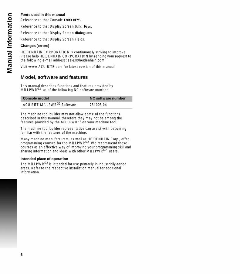
Run options soft keys ............................................................................................ 93Program saving ...................................................................................................... 94
Saving a program .............................................................................................. 94
5.2 Program Mode Functions
Program type filter ................................................................................................. 95USB access............................................................................................................ 95
5.3 Creating Programs Overview
New part program.................................................................................................. 96
6.1 Conversational Programming
Programming considerations ................................................................................. 98“From” and “To” points ................................................................................... 98Depth of cut ...................................................................................................... 98Pass .................................................................................................................. 98Tool offset......................................................................................................... 99Datum selection................................................................................................ 99Absolute vs. incremental dimensions ............................................................. 100Continuous milling .......................................................................................... 100
Fundamentals for Creating a Program ................................................................. 101Entering milling steps ..................................................................................... 101Adding/inserting milling steps......................................................................... 102Editing or deleting a milling step..................................................................... 102Program errors ................................................................................................ 103Program edited ............................................................................................... 103Step Form Validation....................................................................................... 104
Running a Program .............................................................................................. 105Skewing a part ................................................................................................ 105
Establishing a datum............................................................................................ 107Overview......................................................................................................... 107Steps to establish the datum.......................................................................... 108X axis datum ................................................................................................... 109Y axis datum ................................................................................................... 109Z axis datum.................................................................................................... 109Retract Z ......................................................................................................... 110Using an electronic edge finder ...................................................................... 110Setting the datum on an edge ........................................................................ 111Setting the datum at the centerline ................................................................ 112Setting the datum at the center of a circle ..................................................... 112Test the datum setting.................................................................................... 113Testing a MILLPWRG2 program...................................................................... 114Single step ...................................................................................................... 115Dry run ............................................................................................................ 115Graphics only .................................................................................................. 115Skipping steps in a program............................................................................ 115

18
Machining your part ............................................................................................. 116Potentiometer for feedrate override .................................................................... 117Manually positioning the quill ............................................................................. 118
6.2 Folders
Folder functions ................................................................................................... 119Folders ............................................................................................................ 119Creating a folder ............................................................................................. 119Naming a new folder ...................................................................................... 120Deleting a folder ............................................................................................. 120Saving a program ............................................................................................ 120Naming a program .......................................................................................... 121Deleting a program ......................................................................................... 121Loading a MILLPWRG2 (MPT) program .......................................................... 122Importing a DXF drawing ................................................................................ 123
G-code programs ................................................................................................. 124G-code editing capabilities .............................................................................. 124Loading a G-code program.............................................................................. 125Running a G-code program ............................................................................. 125Starting or stopping a G-code program .......................................................... 126
G-code and M-Code definitions ........................................................................... 127G-code ............................................................................................................ 127M-Code definition ........................................................................................... 131Additional G-code conventions for MILLPWRG2............................................. 134
Backing up a program .......................................................................................... 135Copy and paste programs............................................................................... 135Program errors................................................................................................ 136
7.1 Demonstration Program
Overview ............................................................................................................. 138Selecting datum.............................................................................................. 138
Begin programming ............................................................................................. 139Selecting a tool ............................................................................................... 139Programming a line......................................................................................... 140Programming an arc........................................................................................ 141Programming the connecting Line.................................................................. 142Programming the lower vertical Line.............................................................. 143Programming the lower angle Line................................................................. 144Programming the upper angle Line ................................................................ 145Programming a blend...................................................................................... 146Closing the contour......................................................................................... 147Tool Change for the bolt hole pattern ............................................................. 148Programming the bolt circle............................................................................ 149Tool change for the rectangular pocket .......................................................... 150Programming the rectangular pocket ............................................................. 151
Testing the program ............................................................................................ 152

ACU-RITE MILLPWRG2 19
Run Options.................................................................................................... 152Dry run with table movement ......................................................................... 152
Running the program ........................................................................................... 153Tool changes........................................................................................................ 154Clearing the program ........................................................................................... 154
8.1 Milling and Drilling
Overview ............................................................................................................. 156Selecting a tool ............................................................................................... 157
Repeatable tool length offsets............................................................................. 160Programming a tool......................................................................................... 160Changing to a tool of unknown length in DRO mode ..................................... 161Changing to a tool of unknown length in a program....................................... 162
Position/Milling .................................................................................................... 163Position / Drill .................................................................................................. 163Line ................................................................................................................. 164Arc................................................................................................................... 165Blend/chamfer................................................................................................. 166Contour ........................................................................................................... 169
Rectangular and circular contours........................................................................ 170Rectangular milling functions............................................................................... 171
Rectangle pocket ............................................................................................ 171Rectangle frame.............................................................................................. 173Rectangle face ................................................................................................ 175Rectangle slot ................................................................................................. 177
Circular milling functions...................................................................................... 179Circle pocket ................................................................................................... 179Circle frame..................................................................................................... 181Circle ring ........................................................................................................ 183Circle helix....................................................................................................... 185Radial slot........................................................................................................ 186
Hole patterns ....................................................................................................... 187Row of holes................................................................................................... 187Hole frame and array....................................................................................... 189Bolt circle patterns .......................................................................................... 191
8.2 Additional Milling Functions
Step functions soft key........................................................................................ 192Explode ........................................................................................................... 192Reverse step................................................................................................... 193Reverse path................................................................................................... 193Change steps.................................................................................................. 194Shift/Rotate steps ........................................................................................... 194Delete steps.................................................................................................... 195Copy/move steps ............................................................................................ 195
Custom pockets................................................................................................... 196

20
Custom pocket ............................................................................................... 196Island .............................................................................................................. 197
Advanced Custom Pocket Machining.................................................................. 199Pilot Drilling..................................................................................................... 199Rough Milling.................................................................................................. 200Bottom Finishing............................................................................................. 201Side Finishing.................................................................................................. 202
Repeat, rotate ... .................................................................................................. 203Repeat ............................................................................................................ 203Rotate ............................................................................................................. 203Mirror .............................................................................................................. 204
Other steps.......................................................................................................... 205Engrave line .................................................................................................... 205Engrave arc ..................................................................................................... 206Comment step................................................................................................ 207Auxiliary functions........................................................................................... 207Dwell............................................................................................................... 209Reference point .............................................................................................. 209
9.1 Geometry Calculator
Overview ............................................................................................................. 212Accessing the geometry calculator...................................................................... 212
Geometry calculator layout ............................................................................. 213Geometry listing ............................................................................................. 213Geometry graphic ........................................................................................... 213
9.2 Geometry User Interface
Adding geometry features to listing .................................................................... 214GeoPoint ......................................................................................................... 214GeoLine .......................................................................................................... 214GeoArc............................................................................................................ 214
Finding geometry solutions ................................................................................. 214Managing geometry results................................................................................. 216Returning features to the part program ............................................................... 217Geometry calculator functions............................................................................. 217
Clear calculator .............................................................................................. 217Loading and saving calculator contents .......................................................... 217Loading the part program into the geometry calculator.................................. 217
Program example................................................................................................. 218Locating points B and C.................................................................................. 218
Creating the program........................................................................................... 218Step 1 ............................................................................................................. 218Step 2 ............................................................................................................. 219Step 3 ............................................................................................................. 220Finding the points of tangency ....................................................................... 221Returning the line coordinate.......................................................................... 221

ACU-RITE MILLPWRG2 21
Returning the arc feature ................................................................................ 222Finishing the program ..................................................................................... 222
9.3 RPM calculator
RPM functions ..................................................................................................... 223Using the RPM calculator ............................................................................... 223RPM dialogue.................................................................................................. 223
10.1 Setup
Overview ............................................................................................................. 226Setup............................................................................................................... 226Job setup ........................................................................................................ 226Installation setup............................................................................................. 226Tool table ........................................................................................................ 226Message log ................................................................................................... 226
Job setup ............................................................................................................. 227Job setup ........................................................................................................ 227Scale factor ..................................................................................................... 228Feed rate ........................................................................................................ 229Display ........................................................................................................... 229Parts counter................................................................................................... 230Job clock ......................................................................................................... 230Probing............................................................................................................ 230
Tool table ............................................................................................................. 231Message log ........................................................................................................ 231Service files ......................................................................................................... 232
11.1 Auxiliary Machine Interface (AMI)
Machine Functions Menu .................................................................................... 234
12.1 Updating System Software
Software update .................................................................................................. 236Procedure for updating the software................................................................... 236
13.1 Simulators for Windows PCs
Overview ............................................................................................................. 238Simulation software for R6 and newer ........................................................... 238Off-line simulation software for prior to R6 .................................................... 238
System requirements .......................................................................................... 238On screen keypad................................................................................................ 238Keyboard shortcuts.............................................................................................. 239
13.2 Virtual Machine Simulator Software
Simulation software for R6 and newer ................................................................ 242

22
Installation............................................................................................................ 242Operation ............................................................................................................. 242Updating .............................................................................................................. 243
MILLPWRG2 Software .................................................................................... 243Virtual Machine Simulator ............................................................................... 243
Uninstalling .......................................................................................................... 243Control Panel ....................................................................................................... 244
State ............................................................................................................... 244Display ............................................................................................................ 244Keypad ............................................................................................................ 245Hardlock.......................................................................................................... 245Network .......................................................................................................... 245NC-Share......................................................................................................... 246Control buttons ............................................................................................... 246
13.3 Windows Off-Line Software
Off-line simulation software for prior to R6 ........................................................ 247Installation............................................................................................................ 247Operation ............................................................................................................. 247Updating .............................................................................................................. 248

Introduction

24 1 Introduction
1.1
MIL
LP
WR
G2
1.1 MILLPWRG2
The ACU-RITE MILLPWRG2 control is a workshop-oriented contouring control that enables you to program conventional machining operations right at the machine in an easy-to-use conversational programming language. It is designed for milling and drilling machine tools, with up to 3 axes.
MILLPWRG2 was developed to satisfy the wants and needs of tool and die makers and other machinists where manual and automated operation are both useful and needed. MILLPWRG2 will enable you to maximize your throughput by significantly reducing set-up time, scrap, and other non-productive operations, thereby increasing your efficiency, productivity and profitability.
The MILLPWRG2 has many powerful features that will improve your productivity. The screen layout is clearly arranged in such a way that the functions are easy to access, fast and user friendly.
MILLPWRG2 is a closed-looped system with positioning feedback provided by ACU-RITE precision glass scales (1µm/0.00005" resolution). MILLPWRG2 also includes Position-Trac™, an advanced, unique feature that enables you to easily, quickly and accurately re-establish work piece zero after shutting down, or power loss.
ACU-RITE conversational and G-code format
The ACU-RITE conversational programming format is a method of writing programs; g-code (ISO) programming can be used and run. Basic editing of g-code programs is also possible. Preview graphics in the editor illustrate the individual machining steps for programming the contour as well as the corresponding tool path generated. A production drawing does not need to be dimensioned for NC programming, the MILLPWRG2 can be programmed using the dimensions directly from the production drawing. The programming format is the same as used in previous MILLPWR products. Always verify old programs before machining with MILLPWRG2.

ACU-RITE MILLPWRG2 25
1.1
MIL
LP
WR
G2Powering up
Turn the power switch On [1], (to the I position) on the MILLPWRG2 console which is located on the back of the unit.
Follow the builder’s instructions to turn off the machine.
The start up screen with 3 soft keys will be displayed; Shut Down, Find Home, and Cancel. After pressing either the Find Home, or Cancel soft key, the default DRO screen will be displayed.
If a program was loaded when the MILLPWRG2 was shut down, that same program will be reloaded when the unit is powered up again.
The MILLPWRG2 console does not disconnect the power supply to the spindle motor. It can only be disconnected by turning off the main power supply.
It is strongly recommended that the MILLPWRG2 performs the Find Home feature at start up, prior to any other action taken.
If the MILLPWRG2 did not perform the Find Home feature at start up, press the Datum soft key from the default DRO screen to display the Home soft key. Press the Home soft key then the Find Home soft key will be displayed.

26 1 Introduction
1.1
MIL
LP
WR
G2 E-STOP and shutdown
The E-STOP is used for emergency program shut down by turning off the servo motors.
When the E-STOP button is pressed, the servo motors are stopped, and the quill can be raised.It does not shut down the spindle motor.
When the STOP key is pressed once, the servo motors pause, but are still active. All axes are locked, and can not be moved.
The program can now either continue by pressing the GO key, or stopped by pressing the STOP key a second time.
If the STOP key is pressed a second time canceling the program, the spindle motor must be stopped, and the tool raised before moving any of the remaining axes.
Shutting down the MILLPWRG2 system is done by using the Shutdown soft key.
Press the Shutdown soft key to power down the control, so that the main switch can be turned off. Wait for the indication that it is OK to turn power off.
Press the Restart soft key to reboot the control, shutting down and subsequently starting back up.
Press the Cancel soft key to cancel and exit the shut down procedure.
The E-STOP does not shut down the spindle motor. The spindle motor must always be manually stopped using the spindle switch to stop the motor, and the cutting tool.
Always shutdown the MILLPWRG2 before turning power off to the machine. Refer to the builder's instructions for for additional information on turning power off.

ACU-RITE MILLPWRG2 27
1.1
MIL
LP
WR
G2Emergency stop (E-STOP)
Press E-STOP to take all axes servos offline. This ends all machine movement, and allows the quill to be raised to move the tool out of the way.
To reset the E-STOP, turn the rotary switch clockwise in the direction of the arrows. The switch pops outward, and is reset.
Resetting E-STOP does not reactivate the servos.
Activating/Resetting the Servos
For safety reasons, the mill powers up with the servomotors disengaged. While the servos are disengaged the mill axes cannot move under servo power. The axes can be manually positioned if necessary.
Reset the servos as follows:
If a limit switch disengaged the servos, manually reposition the machine inside its normal range of travel.
If a miscount occurs, press the Find Home soft key to reset the servos and return all axes to their home position.

28 1 Introduction
1.1
MIL
LP
WR
G2 Find home
You should find home before a program is run, or immediately after startup.
During start up, the Find Home soft key is provided on the start up screen soft key area.
If the find home step is not performed at initial start up, it can be initiated at any time during operation. Press the Datum soft key, then press the Home soft key, and then press the Find Home soft key.
A 3 axes system will move the table and quill. They will automatically move a few inches along the Z, Y, and then X to find home. If a W axis exists (i.e. coupling knee to quill) then the control will prompt you to move the W manually to home it.
A 2 axes system will move the table. The table will automatically move a few inches along the Y, and then X to find home. Then the control will prompt you to move the Z quill manually to home it. If a W axis exists (i.e. coupling knee to quill) then the control will prompt you to move the W manually also to home it.
When finding home, the MILLPWRG2 will use (on machines equipped with ACU-RITE glass scales), the Position-Trac™ distance-encrypted reference mark line pattern. This line pattern allows MILLPWRG2 to accurately find home and re-establish workpiece zero from any position.
Position-Trac will accurately re-establish workpiece zero after power loss, or shut down. After home has been found, the tool’s position (relative to the most recent datum set) will be displayed.
Before finding home with a 2 axes system, the quill must be fully raised first.
Finding home applies to the X, Y, Z, and W axes.
Not finding home before moving the table will risk exceeding the table's software travel limits, and possible damage to the machine, and the MILLPWRG2 system.
Programs will not be allowed to run if the homing process does not complete successfully.
The Find Home soft key is not available if there is an error, and the front panel LED indicator is flashing. The error must be corrected, and then cleared from the message log. Then homing is allowed. Refer to Chapter 10 "Message log" on page 231 for information on opening the message log and clearing errors.

ACU-RITE MILLPWRG2 29
1.1
MIL
LP
WR
G2Disengage Z axis feature
MILLPWRG2 provides the flexibility to switch between 2 axes and 3 axes operation.
Disengaging the Z axis drive:
Leave the Z Begin field blank when programming a step, or a one time milling operation.
Raise the quill, then loosen the quick release knob [1] on the front of the Z axis drive system.
When a program step, or milling operation is then performed, the operator is prompted to manually position the quill.
Re-engaging the Z axis drive
Raise the quill handle to seat the ball screw into the nut block (e.g. this would be similar to hitting a dead stop).
Tighten the quick release knob [1].

30 1 Introduction
1.1
MIL
LP
WR
G2 Writing programs
Overview
The MILLPWRG2 allows many features to be used without having to write a program. For operations that repeat, or complex machining it is best to write a program. Before writing a program, determine the work-holding device and the location of Part Zero (the point to which all movement is referenced). Since absolute positions are defined from Part Zero, try to select a location that directly corresponds to dimensions provided on the part print, such as the lower left corner of the work. Then you can develop a program. The following is a general approach to programming:
First, select the unit of measurement (Inch/MM) using the MM key. This will place the DRO in the required unit of measure, and all dialogues will use the selection. If the selection is changed after data has been entered, the MILLPWRG2 will convert the data to the new unit of measure.
The first step in a program selects the tool that is to be used. It’s size can be entered in either Inch or MM regardless of the unit of measure selected in the DRO. The Tool dialogue provides fields for data input for the tool position. This is a tool change position, a location away from the work area where the axes can return for safe tool changing. Tool Position will use the unit of measure that has been selected for the DRO.
The remaining steps in the program describe the required moves, single cycles, and Tool changes to complete the machining.
The next to the last step in the program returns the axes to the Tool change position and ends the program.
After writing a program, verify it. Run it to troubleshoot for errors. Verify that all programmed moves are safe, and accurate to the part print dimensions.
Setup the work piece into the intended holding device. First run the program in Single-Step Mode to verify that both the
program and the setting of Tool Offsets are correct. Single-Step Mode allows you to run the program step-by-step. Make any necessary corrections. Once verified, the program can be run in Auto Mode.
When the finished program is ready for production, back it up on a USB memory device.
If there is an interruption to the power supply, the program is not lost. The program is periodically saved. Verify that the most recent steps (prior to the power failure) are in the program. The fixture zero location is also remembered.

ACU-RITE MILLPWRG2 31
1.2
Op
era
tin
g i
n 2
Axe
s a
nd
3 A
xe
s M
od
es1.2 Operating in 2 Axes and 3 Axes
Modes
Overview
The MILLPWRG2 is capable of running a 2 axis machine or a 3 axis machine. When operating in 2 axes mode, all Z moves must be made manually. When operating in 3 axes mode, the Z axis can be switched to manual as needed. This section provides some general guidelines on how to use each of these modes.
Program steps on 2 axis systems
When programming steps in 2 axes mode, not all of the step dialogue’s Z axis fields shown in the manual are available. However, the system will pause and provide prompts whenever a Z move is required.
When prompted, there are two ways to set the Z depth:
To set the Z depth by using the incremental DRO display bar graph:
Switch to the incremental display mode by pressing the ABS/INCR key to toggle between absolute and incremental modes.
In incremental mode, a bar graph is displayed below each axis position. Under the Z axis position, move the small blue indicator to the center of the bar graph which will move the Z axis position to 0 and press GO.
After drilling to depth, raise the quill and press the GO key to continue running the program.
For pocket steps, raise the quill and press GO when prompted.
To set the Z depth by using the Zero Z soft key which is also located in the incremental DRO display:
Move Z to the surface of the part or a known reference position. Press the Zero Z soft key. Move Z to the desired depth. The INC display shows how far Z has
been moved from the reference position. Press the GO key to continue running the program.
If an additional pass is needed for a step, press STOP to end the program and run the step again.
It may also be necessary to repeat a set of steps for each pass in a program.
The Z prompts to raise the quill require a Z retract height. Set Z retract in the Datum dialogue prior to running a program to ensure that the quill is in the home position before the XY table moves.

32 1 Introduction
1.2
Op
era
tin
g i
n 2
Axe
s a
nd
3 A
xe
s M
od
es Coupled axes in 2 axes mode
In 2 axes mode, either the W axis or the Z axis can be moved to change the depth of the cut. Moving the W axis while running a program or single cycle step will not cause a program fault.
For most pockets or paths, W axis motion does not adversely affect the current step’s Z target position.
For custom pockets, contour steps, and engrave steps, the Z axis INC display will not account for any W motion, and will not show the correct distance to subsequent Z target moves within the current step. If you choose to move W, use the DRO’S ABS display value to correctly position the Z axis.
The INC display is corrected for any W motion at the start of the next step. Position / Drill steps and hole pattern steps are correct for anyW motion.
Selecting 2 axes mode on 3 axis systems
To run an entire program in 2 axis mode on a 3 axis system:
Disengage the quill assembly from the motor before pressing the GO key. A prompt will appear indicating that the quill is disengaged.
If this is intentional, press GO and the program will run in 2 axis mode.
To program a specific step to run in 2 axis mode:
For Drill steps, select Position for the Z operation type. For Pockets, clear the Z Begin depth field.
When the step is run, the Z axis servo motor will be turned off to allow manual movement.
Coupled axes in 3 axes mode
In 3 axis mode, moving the W axis while running a program or single cycle step will cause a program fault. The default threshold of motion allowed is 2 mm. The amount of motion allowed in the W axis before causing a fault can be configured through Advanced Configuration in the Installation Setup area. The machine parameter is “Axes -> ParameterSets -> PW -> CfgControllerAuxil -> checkPosStandstill.” Entering a value of "0" disables the monitoring and allows any amount of motion in the W axis without error. Please refer to Section 4.6 of the Installation Manual for more information about using the Installation Setup area and making changes to Advanced Configuration.
Follow all manual Z motion prompts. Also refer to the prior section “Program steps on 2 axis systems.”

ACU-RITE MILLPWRG2 33
1.3
Co
nso
le1.3 Console
Operating console
The ACU-RITE MILLPWRG2 Console has a 12.1-inch Flat-Panel Color Screen Display. The following list of items are located on the front panel.
See "DRO display screen" on page 43 for mapping information of the start up screen.
See "Console keypad" on page 42 for a full description of the console keypad layout. The individual keys are fully described on page ii of the inside front cover.
The following features are located on the front panel of the console:
See "Calculator" on page 40 for a full description of the calculator keypad.
Rear panel
The ACU-RITE MILLPWRG2 DRO rear panel has the following list of items located on the panel.
1 Color flat panel screen display. 2 Emergency “E” Stop3 Soft keys4 Power On indicator light / Error indicator light5 Potentiometer for feed rate override6 Go, Pause/Stop, Navigation keys, and Move Table keys7 Axis keys8 Console keypad9 USB Port
1 Power switch2 Power connector3 Servo Power connector4 Earth (ground) terminal5 Ethernet port6 USB port7 KT 130 Edge Finder8 Pendant (Remote switch)9 RS-232-C connector (only available on ID 745604-xx)10 Auxiliary Machine Interface (AMI); for future expansion.11 Servo connector (X, Y, and Z)12 Grounding Edger Finder13 Encoder Inputs (W and Z axis)

34 1 Introduction
1.3
Co
nso
le Screen navigation
The MILLPWRG2 display layout changes between DRO Mode and PGM (Program) Mode by pressing the DRO/PGM key. The following illustrates the differences between the two screen modes.
DRO mode display
In general, the display changes as different functions are activated. Soft keys in the lower display area change per the function selected. Soft keys perform their associated function by pressing the key directly below it. Basic procedures and features remain the same regardless of which mode is selected. For a complete description of the display areas see "DRO screen" on page 53.
PGM mode display
When PGM mode is selected, the display changes from DRO mode to display program functions and graphics. Soft keys change to programming functions. All soft keys are run by pressing the corresponding hard key located directly below it. See "Status Bar display" on page 54 for complete descriptions.
1 Status Bar display for Servo Motor Status, Feed rate, Tool, Datum, Scale, Skew, (Inch/MM), Estimated Time, Part Clock, Parts (run), Job Clock, and Time of Day. See "Status Bar display" on page 54.
2 Axes Display (current position). 3 Operator Intervention Message line (OIM).4 Soft keys display area.5 Dialogue box display area for milling functions.
1 Status Bar display for Servo Motor Status, Estimated Time, Tool, Datum, Scale, Skew, (Inch/MM).See "Status Bar display" on page 54.
2 Display window of graph simulation.3 Operator Intervention Message (OIM).4 Soft keys display area.5 Program name.6 Program steps.

ACU-RITE MILLPWRG2 35
1.3
Co
nso
leDialogues and drop down menus
This manual provides complete information where specific examples of actions are being explained.
As a general overview of the dialogues provided by the MILLPWRG2, several fields are likely to be provided for input. To navigate a dialogue, use the ARROW keys to select the desired field. After entering the data into a field, press either the ENTER key, or the UP or DOWN ARROW keys to move to the next field. Exiting a field with one of these key methods will retain the entered data in that field.
When the required data has been entered, press the USE key to accept the data entered for use in that specific function.
Most dialogues contain Drop Down menus. Specific milling functions may require additional information. The choices available are provided in a drop down menu. In most cases, they are also provided as soft keys. The choices can be selected from either location.
Operator prompts
For actions that require immediate input to continue the operation an operator prompt will be displayed by the MILLPWRG2 in the message bar. The required data can be entered with the numerical keypad, and in some instances using the alphanumeric on screen keyboard.
Cursor
The MILLPWRG2 uses a highlighted cursor to mark a field for selection or editing. In some instances, the cursor will default to a field without highlighting the field. Use the ARROWS keys to move the cursor. The UP and DOWN ARROWS move the cursor through the fields available. The RIGHT ARROW will open a field that contains more choices, or subfolders in the folder tree window. The LEFT ARROW will close the menu, or subfolders.
The cursor will also change from a highlighted bar to a text cursor when a field selected is having data entered.
Three axis specific fields are not displayed when in two axis mode.

36 1 Introduction
1.3
Co
nso
le General operating guidelines
General operating guidelines for the MILLPWRG2.
Additional operation soft keys are located in the soft key area along with task selection and dialogue. The soft keys change in relation to the task being performed.
Selection of a particular soft key that requires additional information may open a popup menu [1].
A soft key may open a dialogue menu that requires input necessary to continue with the operation selected.
The status bar in the top of the display is constant, and reflects only what has been selected for the current program.
Use the Context Sensitive Help (INFO key) feature when assistance is desired. This is an intuitive feature that aids the user by going directly to the section in the manual in relation to the feature, or key that has been selected to obtain assistance with.
A feature that is not available will have it's soft key disabled.
Soft keys that have a small arrow in the upper left hand corner indicates that a popup menu is available when the key is selected for additional choices.

ACU-RITE MILLPWRG2 37
1.3
Co
nso
leOperating modes
The MILLPWRG2 has two main operating modes: DRO and PGM (Program). These are accessed from the front panel hard key. This is a toggle key.
DRO mode shows the current position of each axis relative to current datum. In DRO mode, manual machining, and Single Cycles can be performed. Tool selection, units, along with most setup features can be accessed.
Program mode PGM, displays the list of program steps and part-view graphics. New programs can be created as well as editing existing programs. Programs, new or existing, can be saved, deleted, or copied using program functions.
A USB pointing device e.g. mouse, trackball, etc. may also be used. If a pointing device is being used, the action of clicking on a soft key button is the same as pressing the corresponding soft key. A USB keyboard can also be used for data entry and cursor control.

38 1 Introduction
1.3
Co
nso
le Popup menus
Within the soft keys, additional features may be available in program mode. A soft key that has a down arrow in the lower right hand corner indicates that additional soft keys are available for that feature.
As an example, pressing the Program Steps soft key (in PGM mode) opens another set of soft keys available for this function. Then you will notice an up arrow on most of the soft keys. This indicates a popup menu will open when that key is pressed.
Soft keys for PGM provide access to edit existing programs, or create a new program. Sub menus provide dialogue for machining operations such as milling a line, an arc, engraving, drilling and creating pockets.
Pressing the required operation step soft key will open a popup menu to further define the machining operation required.
A selection for a popup can occur in one of two ways:
Use the shortcut number to the left of the feature; for example, pressing 9 on the numeric keypad will select the Circle Ring dialogue.
Or use the Up and Down arrow keys to highlight the feature to be used, then press ENTER.
When the type of machining operation has been selected, the corresponding dialogue opens so that the required data can be entered.
A dialogue in DRO mode will retain the previous data entered making it possible to re-run the previous operation without having to re-enter all the data.
At anytime when entering data into a dialogue the calculator can be accessed by pressing the CALC key.
Soft keys for CALC provide access to additional math functions such as trig functions.
When a dialogue is activated, it is not possible to change to another dialogue. The current dialogue must be exited by pressing USE to save the data in the dialogue or pressing CANCEL to discard the data.

ACU-RITE MILLPWRG2 39
1.3
Co
nso
leKeyboard
An on screen QWERTY keyboard will automatically popup when you enter a field that requires text information input.
The keyboard becomes visible (popup) when text, and numerical information is required for an action (e.g. saving a program, or entering text for engraving).
Use the ARROW keys for navigation of the cursor to go to the desired character and press ENTER to select the character.
When the information has been entered using the keyboard, press the Save soft key. The keyboard will disappear from the screen. The keyboard will also be removed from the screen when the CANCEL key is pressed.
When using a USB keyboard, the on screen keyboard can be disabled by pressing the Keyboard soft key. The on screen keyboard will remain disabled until it is enabled by pressing the Keyboard soft key again. When the console goes through a power cycle, the key board will retain its setting prior to the power cycle.
Special characters
The keyboard also provides a “Special Characters” display which is accessed by the “(#*\!...” key.
Arrow over to the “(#*\!...” key to highlight the key, and press the the ENTER key.
Navigational soft keys
The following navigational soft keys are always available on the keyboard.
The “Up Arrow” key switches the keyboard from upper to lower case letter mode, or from lower to upper case letter mode depending on the current keyboard mode.
The “Abc” key switches the keyboard from the special character key mode to the alpha numeric key mode.
The “(#*\!...” key switches the keyboard from the alpha numeric key mode to the special character key mode.

40 1 Introduction
1.3
Co
nso
le Editing keys
The following keys are available for editing text on the keyboard.
The Copy key will copy the highlighted text in the text field.
The Paste key will paste to the text field text that was previously highlighted, and copied.
The Clear key will remove all text in the text field.
The back space key will delete text in the text field one character at a time.
Calculator
Numeric keypad
The numeric keypad on the front of the console resembles a standard calculator with keys for numbers 0 through 9, four math function symbols (+, -, x, and ÷), a decimal point, and a positive/negative sign (+/-).
The calculator is accessible from nearly any screen or field. Press the CALC key to access the “stand-alone” calculator. The math function soft keys are displayed in the soft key area. Calculations can be entered directly into a highlighted field.
Using the calculator in an entry field in a dialogue requires the operator to press the ENTER key to run the calculation. To move to the next field using the ENTER key requires the operator to press ENTER a second time.
Anytime data is entered into an entry field in a dialogue and the value is changed using the +/- key, the operator is required to press the ENTER key to use the value change. Moving to the next field using the ENTER key requires the operator to press ENTER a second time.

ACU-RITE MILLPWRG2 41
1.3
Co
nso
leContext sensitive help
The MILLPWRG2 uses an intuitive method to aid the user when assistance is required. When assistance is needed with a feature, the User Manual can be displayed directly at the point which describes the feature.
To use this help, in this example, the console is in PGM mode, and a Linear Engraving cycle is being programed. It is desired to see descriptions of the cycle parameters, and the cycle itself. The following steps describe the actions needed to take.
Using context sensitive help
Press the INFO key to open the on screen User Manual.
This will display a new window containing the section in the User Manual, opened directly to the description of the desired feature. This is the active window when Context Sensitive Help is activated.
To activate the Contents View on the left side of the display, press the Contents View soft key. This allows the user to see all available topics from the User Manual. The Forward and Back soft keys will navigate the users previous history. The Previous Topic and Next Topic soft keys will select the previous and next topic in the manual contents (shown in the Contents View on the left hand side). These soft keys allow the user to select other sections of the User Manual while in Context Sensitive Help. Using these keys will navigate the User Manual even if the Contents View is hidden.
The following describes the action, and use of the soft keys:
The Back soft key navigates one page back per key press to a previous page that was viewed from the history. History is not cleared when the Help Screen is exited.
The Forward soft key navigates one page forward per key press from the viewed pages in history.
The Previous Topic soft key navigates one Topic up in the contents window per key press.
The Next Topic soft key navigates one Topic Down in the contents window per key press.
The Contents View soft key is a toggle key to show/hide the contents view on the left hand side of the display.
To close, press the Exit soft key.

42 1 Introduction
1.3
Co
nso
le Console keypad
The following keys are located on the console keypad. There is also a quick reference guide located at the beginning of this manual on page ii of the inside front cover.
1 Axis keys, use to select the required axis.2 Numeric keys, use to enter numeric data.3 CANCEL key, use to cancel current action.4 CLEAR key, use to clear selections such as values entered in a
field.5 ARROW keys, use to navigate around the screen, and highlight
dialogue fields. Also used to move the table axes.6 STOP key, use to pause, or stop a program that is running, or a
machine operation.7 GO key, use to start, or resume a program.8 USE key, use to complete an operation, i.e. data values entered in
a dialogue.9 ENTER key, use to activate selections, and entries.10 +/- key, use to toggle key for “Plus/Minus” data entry.11 CALC key, opens the fully functional calculator.12 Function keys, select appropriate key for quick access to the
function and data entry.13 Milling function keys. Selection of appropriate key provides direct
access to the milling function dialogue.
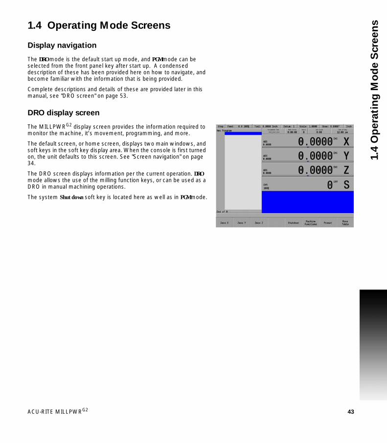
ACU-RITE MILLPWRG2 43
1.4
Op
era
tin
g M
od
e S
cre
en
s1.4 Operating Mode Screens
Display navigation
The DRO mode is the default start up mode, and PGM mode can be selected from the front panel key after start up. A condensed description of these has been provided here on how to navigate, and become familiar with the information that is being provided.
Complete descriptions and details of these are provided later in this manual, see "DRO screen" on page 53.
DRO display screen
The MILLPWRG2 display screen provides the information required to monitor the machine, it’s movement, programming, and more.
The default screen, or home screen, displays two main windows, and soft keys in the soft key display area. When the console is first turned on, the unit defaults to this screen. See "Screen navigation" on page 34.
The DRO screen displays information per the current operation. DRO mode allows the use of the milling function keys, or can be used as a DRO in manual machining operations.
The system Shutdown soft key is located here as well as in PGM mode.

44 1 Introduction
1.5
Acce
sso
rie
s Program display screen
From the DRO mode, press the DRO/PGM key, and the display changes to program mode showing the currently selected or loaded program.
When programing a job, the display activates a graphic view of the program. While the program is running, the operation that is being performed is graphically shown as well. The VIEW key provides features to configure the graphic area.
For more information, see "Program function screen" on page 79.
1.5 Accessories
Electronic edge finder
The electronic edge finder KT 3D enables the ability to teach positions, find the center point of a circle, or locate datum (work piece zero) by touching off on the part. Advantage of an electronic edge finder is that it instantly senses when contact is made with the point (even if the axis over traveled).
Simulation Software for Windows PCs
The MILLPWRG2 simulation software provides a convenient way to write part programs and simulate machine behavior using a Windows computer. For more information, see "Simulators for Windows PCs" on page 238.

Machining
Fundamentals
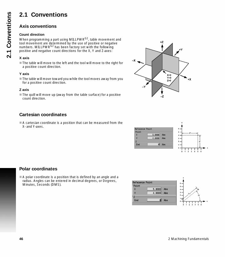
46 2 Machining Fundamentals
2.1
Co
nve
nti
on
s 2.1 Conventions
Axis conventions
Count direction
When programming a part using MILLPWRG2, table movement and tool movement are determined by the use of positive or negative numbers. MILLPWRG2 has been factory set with the following positive and negative count directions for the X, Y and Z-axes:
X axis
The table will move to the left and the tool will move to the right for a positive count direction.
Y axis
The table will move toward you while the tool moves away from you for a positive count direction.
Z axis
The quill will move up (away from the table surface) for a positive count direction.
Cartesian coordinates
A cartesian coordinate is a position that can be measured from the X- and Y-axes.
Polar coordinates
A polar coordinate is a position that is defined by an angle and a radius. Angles can be entered in decimal degrees, or Degrees, Minutes, Seconds (DMS).

ACU-RITE MILLPWRG2 47
2.1
Co
nve
nti
on
sAbsolute and incremental work piece positions
Absolute work piece positions
Absolute coordinates are position coordinates that are referenced to the datum of the coordinate system (origin). Each position on the work piece is uniquely defined by its absolute coordinates.
Example 1: Holes dimensioned in absolute coordinates
Incremental work piece positions
Incremental coordinates are referenced to a previous step within the program, which serves as the relative (imaginary) datum. When you write a part program in incremental coordinates, you thus program the tool to move by the distance between the previous and the subsequent nominal positions. Incremental coordinates are therefore also referred to as chain dimensions.
Example 2: Holes dimensioned in incremental coordinates
Absolute coordinates of hole 4
X = 10 mmY = 10 mm
Hole 1 Hole 2 Hole 3X = 10 mm X = 30 mm X = 50 mmY = 10 mm Y = 20 mm Y = 30 mm
Hole 5, with respect to 4 Hole 6, with respect to 5X = 20 mm X = 20 mmY = 10 mm Y = 10 mm

48 2 Machining Fundamentals
2.1
Co
nve
nti
on
s Setting the datum
Overview
Datum is the workpiece zero or absolute zero, and is a point of reference that the MILLPWRG2 bases all of the part's coordinates from.
A datum must be established for every job. Datum's location may be indicated on the print; or the operator may establish a datum that allows most of the part's dimensions be entered directly using the least amount of calculations.
When establishing datum, it may be easiest to locate a known point on each axis, such as the corner of the part, or a location on a vise or fixture.
Datum can be set at a point on the top surface, a position beneath the surface, or at a point where there's no material present (such as in the center of a circular part). Touching off the edge of a work piece using a tool, or an edge finder can be used when establishing a datum. See "Steps to establish the datum" on page 108.

ACU-RITE MILLPWRG2 49
2.2
Ma
nu
al
Ma
ch
ine
Po
sit
ion
ing2.2 Manual Machine Positioning
Move table
Non cutting mode
You can make or change jog moves when in DRO mode with the servos on.
In mm units the jog increment is 20 microns, 200 microns and 2000 microns respectively.
Changing the mode
Jog move modes are performed at the currently active feedrate. The active Jog is selected by pressing the appropriate soft key, then pressing the appropriate ARROW key to move the table in the direction required. The UP and DOWN ARROWS move the table in the Y axis. The LEFT and RIGHT ARROWS move the table in the X axis. Use the soft keys Move Z Up or Move Z Down to move the Z axis in the desired direction.
Changing the jogging speed
The active jogging speed defaults to the max feed as determined by the machine builder. The jogging speed may be changed by pressing Clear. Enter the new speed in the dialogue and press ENTER. The new value will remain active until set again or on the next power up. The active jogging speed (at 100% override) is displayed in the Jog Mode "ATTENTION" dialogue.
Incremental moves
In DRO Mode, Press the Move Table soft key. Then select the soft key Jog increment required. Then press the ARROW keys (for X and Y) or the soft keys for Z. One jog increment is moved per ARROW key press.
Continuous moves
To manually position the machine using continuous movement, press the Move Table soft key. Make sure none of the incremental Jog keys are highlighted.
Jog Mode Description
Rapid Default rapid speed for continuous jogs. Actual speed determined at machine setup, and can be over ridden using the potentiometer.
Jog: 0.1 Conventional Jog increment set at 0.100”.
Jog: 0.01 Conventional Jog increment set at 0.010”.
Jog: 0.001 Conventional Jog increment set at 0.001”.

50 2 Machining Fundamentals
2.2
Ma
nu
al
Ma
ch
ine
Po
sit
ion
ing Press the appropriate ARROW key (or soft key) to move the table in the
direction required for the axis move. The table will move at the currently active jogging speed. The table will move until the ARROW key is released.
Adjusting the feedrate
The Feedrate Override potentiometer can be used to override the currently active feedrate or rapid rate for machine moves. The switch provides a range of 0% to max% as defined in Job setup, see page 227. Setting the switch to 100% will allow the actual feedrate or rapid rate currently active to be used.
Preset moves
The Preset feature allows the machine to be used manually like a readout. The preset dialogue is used to set a target location. After entering a target location, the INCR display will show the distance between the current position to, and the target position.
Press the DRO/PGM key on the front panel to place the MILLPWRG2 in DRO mode.
Press the ABS/INCR key on the front panel to place the MILLPWRG2 to INCR.
Press the Preset soft key to open the Preset dialogue. Enter the target coordinates for X, Y, and Z. Press the USE key to set the target and exit the Preset dialogue. Press the CANCEL key at any time to cancel and exit the Preset
dialogue.
Manually move the table and/or quill until the INCR axis positions are zero. When the INCR positions are zero, the machine is at the target position.Zero incremental
The INCR display may be set to zero at the machines current location.
Press the DRO/PGM key on the front panel to place the MILLPWRG2 in DRO mode.
Press the ABS/INCR key on the front panel to place the MILLPWRG2 to INCR.
Press the Zero X soft key to zero the X axis. Press the Zero Y soft key to zero the Y axis. Press the Zero Z soft key to zero the Z axis.
The INCR display will show zero. As the table or quill are moved, the INCR display will show the distance from the current position to the zero location.
The machine builder determines the default rapid rate and maximum feedrate at setup. If the MILLPWRG2 is shut down, the configuration file reloads these default rates at the next power up.

DRO Mode and
Calculator

52 3 DRO Mode and Calculator
3.1
DR
O M
an
ua
l D
ata
In
pu
t 3.1 DRO Manual Data Input
Overview
The MILLPWRG2 is in either DRO mode or PGM mode. DRO mode allows data input for short one step machining operations. Manual operation, single step operation, and single commands can be entered. DRO mode also allows the running of programs; See "DRO operations" on page 60.
The following describes the concepts, and formats used with the MILLPWRG2 which are being introduced in this chapter.
DRO Screen Status Bar DisplayMove TableMilling Functions Zeroing an Axis Teach Position Electronic Edge Finder SkewingMilling Function KeysDRO OperationsDRO Mill CyclesCalculator

ACU-RITE MILLPWRG2 53
3.1
DR
O M
an
ua
l D
ata
In
pu
tDRO screen
The DRO screen displays information per the current operation. The DRO mode allows the use of the milling function hard keys, or can be used as a DRO in manual machining operations.
In addition to the information provided in Chapter 1 "DRO mode display" on page 34, the following table describes what is being viewed on the display in DRO mode.
When the console is first turned on, the soft keys Shut Down, Find Home, and Cancel are displayed.
Press the Find Home soft key.
After pressing either the Find Home, or Cancel soft key, the default DRO screen will be displayed.
If the MILLPWRG2 did not perform the Find Home feature at start up, press the Datum soft key from the default DRO screen to display the Home soft key. Press the Home soft key then the Find Home soft key will be displayed.
1 Status Bar displays the servo motor status Stop/Run/Pause, feedrate override, current Tool (blank if none is selected), Datum, Scale, Skew, unit of measure selected (Inch/MM), Estimated Time, Part Clock, Parts (run), Job Clock, and Time of Day. See "Status Bar display" on page 54
2 Display current position of each axis, and relative to the current datum.
3 Operator Intervention Message line (OIM) that provides prompts, and messages to the operator.
4 Soft keys display. The soft keys change per the function that has been selected. Each are activated by the associated hard key that is directly below it. When a soft key appears as being pressed, it is activated. If the key is not pressed in, it is not currently active. Active soft key text changes to yellow text when the feature of the key is not currently available.
5 This window displays program steps if a program is loaded. If no program is loaded, then this window is blank. When a function has been selected (e.g. Pocket), its dialogue box would be displayed in this window.

54 3 DRO Mode and Calculator
3.1
DR
O M
an
ua
l D
ata
In
pu
t Status Bar display
Status Bar Display
Description
Program State
This field indicates the program state: Stop when program is not running, Run when program is running, or Pause when program is paused for operator.
Feed This field indicates the current feedrate of the table or quill.
Tool In DRO mode, this field indicates the current tool selection. In PGM mode, this field indicates the programmed tool for the highlighted step (MPT programs only).
Datum This field indicates the active Datum number.
Scale This field indicates the active Scale factor.
Skew This field indicates the active Skew angle.
Units This field indicates the active display units. All dimensions are displayed in these units (inch or mm). The current feedrate is displayed in these units (inch or mm per minute).
Estimated Time
This field indicates the estimated machining time for the active program. This time assumes the program runs at 100% of the programmed feeds. It does not include the time necessary to perform manual operations such as changing a tool.An unfinished simulation run will result in no time displayed (--:--:--).
Part Clock This field shows the cumulative running time of the current program. The timer is reset when a program is loaded.
Parts This field shows the number of times the current program was run to create a part.
Job Clock This field shows the total elapsed time for the current job. For more information see "Job clock" on page 230.
Time of Day
This field shows the current time.

ACU-RITE MILLPWRG2 55
3.1
DR
O M
an
ua
l D
ata
In
pu
tMove table
The Move Table soft key when pressed will turn on the servo motors. Pressing it again will turn the servo motors off.
The desired feed rate can be set, or it can be left at 100% for rapid feed rate. See "Adjusting the feedrate" on page 50.
To move the table in increments, first select the soft key increment wanted (e.g. 0.001, or 0.01, or 0.1).
A 3 axes system allows the Z axis to be moved by selecting the soft keys Move Z Up, or Move Z Down.
A 2 axes system requires the Z axis to be moved manually.
A 3 axes system allows the X, Y, (and Z) axis can be moved simultaneously by pressing the desired direction ARROW hard keys at the same time.
A 2 axes system allows the X, and Y axis to be moved simultaneously by pressing the desired direction ARROW hard keys at the same time.
Milling function
One Step Milling function may also be referred to as Single Cycle milling functions. Most milling functions can be used as one time machining operations as well as for programming. The BLEND key does not support single operation. Each milling function will either open its own dialogue or allow selection of choices from a soft key popup. These milling function keys are described in more detail later in this chapter.
Always fold in the table crank handles before moving the table using the servos.
The axis move one increment per key press when using step increment. The axis moves continuously until released when using continuous jog.
Single cycle milling functions allow use of internal incremental reference.

56 3 DRO Mode and Calculator
3.1
DR
O M
an
ua
l D
ata
In
pu
t Zeroing an axis
Pressing the Zero X, Zero Y, or Zero Z soft keys will zero the incremental position for those axes.
A datum must be set to establish the point from which all absolute dimensions are based.
Teach position
Whenever X, Y or Z coordinates are being entered, the Teach Position soft key will appear, enabling MILLPWRG2 to be in teach mode and to use the current coordinate(s). MILLPWRG2 will base each coordinate on the current absolute position, and enter that position into the field that is highlighted.
To teach the MILLPWRG2 a coordinate (while programming a milling function e.g. Rectangle Pocket):
Use the ARROW keys to highlight the X, Y, or Z axis fields. Move your tool, indicator, or electronic edge finder to the position
you want to teach. Press the Teach Position soft key to enter that location then press
the ENTER key. The numeric keypad, and calculator functions can be used to adjust
the number. Repeat the steps for each axis and each location that will be used to
teach the MILLPWRG2. Press USE to accept the dialogue or press CANCEL to cancel the
dialogue.
While programming, the MILLPWRG2 can switch between the DRO and PGM screens without losing the program that is either being created, or being edited.
Whenever the Teach Position soft key is available, the Probe soft key is also available. This probe feature allows the location of an edge, midpoint (centerline), or circle center to be entered into the coordinate using the edge finder. Refer to Chapter 6 "Using an electronic edge finder" on page 110.

ACU-RITE MILLPWRG2 57
3.1
DR
O M
an
ua
l D
ata
In
pu
tElectronic edge finder
A HEIDENHAIN Electronic Edge Finder enables you to teach positions, find the center point of a circle, skew a part or locate datum (also referred to as workpiece zero) by simply touching off on the part. The advantage of an electronic edge finder is that it instantly senses when you’ve made contact with the point even when you over-travel.
MILLPWRG2 lets you define the diameter and unit of measure for an electronic edge finder. Once this information has been entered, MILLPWRG2 will automatically compensate for the radius of the tip of the electronic edge finder when performing any of the operations mentioned above.
To teach a coordinate with the edge finder, highlight the appropriate field then slowly move the table (1in/min) until the electronic edge finder touches the workpiece. When the electronic edge finder touches the part’s surface, the coordinate will appear in the field. The electronic edge finder is active whenever an entry field is highlighted.

58 3 DRO Mode and Calculator
3.1
DR
O M
an
ua
l D
ata
In
pu
t Skewing
The skew function automatically compensates for the offset angle of the part when it is not perfectly parallel with either the X or Y axis.
Press the DRO/PGM key to place the MILLPWRG2 in DRO mode. Press the ABS/INCR key to place the MILLPWRG2 in ABS mode. Press the Datum soft key to open the Set Datum dialogue. Enter the Datum Number in the DATUM NUMBER field. Enter the Skew Angle in the SKEW ANGLE field. Press the CANCEL key at any time to cancel and exit the Set Datum
dialogue.
To compensate for the skewed part, touch off on two or more points along one axis, either X or Y. Use an electronic edge finder or a mechanical indicator. At each point selected, press the Teach Position soft key to enter the data.
Always choose a line that you want to make parallel with the table’s X or Y axis, do not enter coordinates along a curve, along two different lines or along a line that’s positioned at a true 45 degree angle. MILLPWRG2 will calculate the skew angle based upon a straight line between the points you’ve entered.
If you’re working with a part that has a rough edge, it’s best to enter multiple points along the straightest edge so that MILLPWRG2 can more accurately calculate the skew angle.
Each datum has its own skew angle. When a new datum is selected, that datum’s skew angle will be used.
The skew feature does not work with G-code programs. Remove any skew angle prior to running a G-code program.

ACU-RITE MILLPWRG2 59
3.1
DR
O M
an
ua
l D
ata
In
pu
tMilling function keys
The following describes in general, the milling function keys.
Most milling functions can be used as one time machining operations. The BLEND key does not support single operation.
Hard Key Function
TOOL opens the SET TOOL dialogue where information regarding the tool can be entered.
RECT opens the popup menu above the Rectangle soft key. Choose the type of rectangle milling that is to be done by selecting it from the popup menu. The required dialogue will open for that choice.
CIRCLE opens the Circle popup menu above the Circle soft key. Choose the type of circle milling that is to be done by selecting it from the popup menu. The required dialogue will open for that choice.
HOLES opens the popup menu above the Hole Pattern soft key. Choose the type of hole drilling that is to be done by selecting it from the popup menu. The dialogue where information can be entered to drill a row, frame, array, or a bolt circle pattern will open.
POS opens the POSITION / DRILL dialogue where information can be entered to move the table to a position in the X & Y direction.
LINE opens the MILL LINE dialogue where information can be entered to mill a line.
ARC opens the MILL ARC dialogue where information can be entered to mill an arc.
BLEND opens the BLEND dialogue while in PGM mode where information can be entered to mill an arc, blending two surfaces together. Also used for chamfer.

60 3 DRO Mode and Calculator
3.1
DR
O M
an
ua
l D
ata
In
pu
t DRO operations
The following explains a few of the machining operations that are available. This example is providing an overview to the operator of the MILLPWRG2 capabilities.
The RECT, or CIRCLE keys as an example access popup menus to further refine the type of milling to be completed. Selecting the type of milling operation required will open the dialogue for that type of milling operation.
An operation is run by pressing the USE key. The CANCEL key can be pressed at anytime to cancel an operation.
Rectangle milling
Press the RECT key on the front panel. The soft key is displayed, and a popup menu appears on the display listing the type of rectangles available for milling.
Rectangle milling example
(e.g. pocket, frame, face, or slot)
Select Pocket from the popup menu.
The popup menu disappears, and the Rectangle Pocket dialogue is displayed.
Enter the data to mill the pocket.
An operation is run by pressing the GO key. While running a graphic representation can be seen by pressing the VIEW key. The STOP key can be pressed at anytime to pause, or stop an operation.

ACU-RITE MILLPWRG2 61
3.1
DR
O M
an
ua
l D
ata
In
pu
tCircle milling
Press the CIRCLE key on the front panel. The soft key CIRCLE is displayed, and a popup menu appears on the display listing the type of circles available for milling.
Circle milling example
(e.g. pocket, frame, ring, or helix)
Select Pocket from the popup menu.
The popup menu disappears, and the Circle Pocket dialogue is displayed.
Enter the data to mill the pocket. Press GO to run the circle pocket.

62 3 DRO Mode and Calculator
3.1
DR
O M
an
ua
l D
ata
In
pu
t DRO mill cycles
The one step milling function are grouped in Four categories as shown in these groups.
Drill Cycles PositionRow of HolesRectangular FrameRectangular ArrayBolt Circle
Rectangular Pocket Cycles Pocket Frame Slot Face
Circular Pocket Cycles Pocket FrameRingHelix Slot
Other one step milling features
Mill LineMill Arc
When a Milling Function key is selected for a single step operation, either a popup menu is displayed, or the available soft keys for that function are provided and its dialogue is opened. When a popup menu appears, further selection is required, then the dialogue is displayed.
The DRO screen is also displayed, showing the current axes location. The RECT, CIRCLE, and HOLES keys, when selected, display a popup menu. These three keys provide additional selections to further specify the type of machining required.
Press the milling function hard key that is to be performed in DRO mode.

ACU-RITE MILLPWRG2 63
3.2
Ca
lcu
lato
r3.2 Calculator
Accessing the calculator
The built in calculator can be used for simple arithmetic, or other math functions. The calculator can be accessed at any time, during most operations.
The mathematical functions; +, -, x, and ÷, can be access at any time using the numerical key pad. These functions are normally accessed while in a field of a dialogue during PGM mode.
Refer to Chapter 9 "Geometry Calculator" on page 212 for a complete description, and how to use the Geometry Calculator to perform complex geometry, and RPM calculations.
Using the calculator to insert data
The calculator can be used in the numeric field of dialogues.
Example, Milling a circle pocket:
The radius of a circle is required in the data input field, and the part drawing provides a diameter dimension.
The diameter dimension can be entered into the dialogue field.
Then press the Divide by key. The ( ÷ ) divide by symbol will appear in the field showing the calculation step.
Then press the 2 key. This will also appear in the field as part of the calculation steps.
Then press the ENTER key, and the result will be entered into the dialogue field.

64 3 DRO Mode and Calculator
3.2
Ca
lcu
lato
r Trig functions
The Trig function calculator can be accessed at any time, during most operations.
To access the calculator’s Trig functions, press the CALC key.
Then press the Trig soft key, and select the function to be used.
The following Trig calculator soft keys are available:
Soft key Description
Sin Trigonometric Sine function
CosTrigonometric Cosine function
TanTrigonometric Tangent function
Open Parenthesis (Used as one of a pair to enclose a sum, or other expression.
Close Parenthesis )Used as one of a pair to enclose a sum, or other expression.
SquareNumber multiplied by itself
Square RootSquare root of a number
More Cmds(see next soft key display area)

ACU-RITE MILLPWRG2 65
3.2
Ca
lcu
lato
rMore Commands, second menu.
Press the CLEAR key to clear the entry field.
To exit the calculator press the CALC key a second time or press CANCEL.
Trig functions
When calculating the Sine, Cosine, or Tangent of an angle, enter the angle first (in decimal degrees), then press the function soft key.
Soft key Description
ArcSinInverse function of Sine
ArcCosInverse function of Cosine
ArcTanInverse function of Tangent

66 3 DRO Mode and Calculator
3.2
Ca
lcu
lato
r

Tool Table
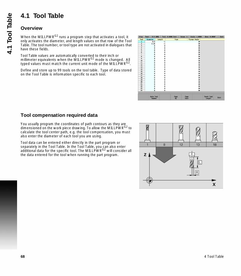
68 4 Tool Table
4.1
To
ol
Ta
ble 4.1 Tool Table
Overview
When the MILLPWRG2 runs a program step that activates a tool, it only activates the diameter, and length values on that row of the Tool Table. The tool number, or tool type are not activated in dialogues that have these fields.
Tool Table values are automatically converted to their inch or millimeter equivalents when the MILLPWRG2 mode is changed. All typed values must match the current unit mode of the MILLPWRG2.
Define and store up to 99 tools on the tool table. Type of data stored on the Tool Table is information specific to each tool.
Tool compensation required data
You usually program the coordinates of path contours as they are dimensioned on the work piece drawing. To allow the MILLPWRG2 to calculate the tool center path, e.g. the tool compensation, you must also enter the diameter of each tool you are using.
Tool data can be entered either directly in the part program or separately in the Tool Table. In the Tool Table, you can also enter additional data for the specific tool. The MILLPWRG2 will consider all the data entered for the tool when running the part program.

ACU-RITE MILLPWRG2 69
4.1
To
ol
Ta
bleTool numbers / tool names
Each tool is identified by a number between 0 and 99. The tool name is its tool number.
The tool number 0 is automatically defined as the zero tool (empty spindle) with the length L=0 and the diameter D=0.
Sign for the length difference ΔL
If the tool is longer than the T1 tool: ΔL > 0 (+).
If the tool is shorter than the T1 tool: ΔL < 0 (–).
The tool length offset can be entered as a known value, or use the Teach soft key. The MILLPWRG2 can determine the offset automatically.
The tool length offset may be entered as a known value, or the MILLPWRG2 may determine the offset automatically. To have the MILLPWRG2 determine a tool’s length offset involves touching the tip of each tool to the part’s Z0 surface, and pressing the Teach soft key. This provides information to the MILLPWRG2 to determine the tool length offset for each tool.
Tool Diameter “D”.
Enter the tool diameter ”D” directly.
Locating the tool table
The Tool Table is accessed from the DRO setup screen.
To activate the tool table, press the SETUP key. Then press the Tool Table soft key.
The Tool Table should not have any tool length for a tool that is not repeatable.

70 4 Tool Table
4.1
To
ol
Ta
ble Tool table
Editing the tool table
When the tool table is open, a new tool can be added, or an existing tool can be edited by changing the existing information for that tool.
To enter a new tool, a blank numbered row will need to be selected.
Using the ARROW keys, highlight the next available blank row number. Highlight the Diameter field, and using the numeric keypad, enter
the tool diameter. Press the ENTER key. ARROW over to the next field and enter the tool Length if it is to be
used. Press the ENTER key. ARROW over to the Type field and press the ENTER key. The Type is
only for informational purpose. From the drop down menu, ARROW down to select the description of
the tool that is being added (e.g. flat end mill). Press the ENTER key. Arrow to the next field and enter the plunge angle. When ramping
into a pocket, this is the angle at which the tool will enter the material.
Press the ENTER key. Continue to add additional tools as necessary. When all tools have been added, press the Exit soft key, or USE key
to save changes to the tool table.
Press the Teach soft key. The MILLPWRG2 calculates the tool length offset for the selected tool putting the data to the length column.
To jump to a specific tool number, press the Goto Tool Number soft key, enter the desired tool number and press the USE key.
It is necessary to first select the unit of measurement before entering values into the tool table.

ACU-RITE MILLPWRG2 71
4.1
To
ol
Ta
bleEditing an existing tool
To edit an existing tool is similar to adding a new tool using the same dialogues.
Highlight the desired field of the tool to be changed. Type in the new value, then press the ENTER key. When all changes have been made, press the Exit soft key.
When running G-code program’s tool block, or a MILLPWRG2 conversational program’s tool step specified by tool number, the tool data is provided from the tool table. As an example, running a G-code T1 M6 block prompts the operator to load tool 1 into the spindle. The tool length, diameter, type, and plunge angle are retrieved for tool #1 in the tool table, and used to adjust the tool path and Z axis position.
Tool table structure
Tool table: Standard tool data
Only add the tool diameter and length if it is repeatable each time it is selected.
Abbr. Inputs
Tool Number by which the tool is called in the program (e.g. tool 2 = T2).
Diameter Compensation value for the tool diameter D.
Length Compensation value for tool length L.
Type Tool type: A popup menu appears where you can select the type of tool being used.
Plunge Angle Angle of plunge cut.

72 4 Tool Table
4.2
To
ol
Da
ta 4.2 Tool Data
Tool-length offsets
Tool-length offset is the distance from Z0 Machine Home to the tip of the tool at the part Z0 (the surface of the work).
Tool-length offsets allow each tool used in the part program to be referenced to the part surface. In an idle state, the MILLPWRG2 does not have a tool-length offset active. Therefore, Tool #0 (T0) is active. When T0 is active, all Z dimensions are in reference to the Z Home position. When you program T1, all Z dimensions become referenced to the surface on which the tool-length offset of Tool #1 was activated.
For machines that do not have a Z axis automatic homing feature, you must set the Z0 position of the Z axis. Usually, it is the fully retracted (Up) position of the quill or machine head. Tool-Length Offsets are referenced to this position.
Because tools differ in length, Z0 axis (Part Zero) is not set the same way as X0 or Y0. The tool-length offset is the distance from the tip of the tool to the top of the part. Enter a length offset for each tool in the Tool Table.
With tool-length offsets active, the Z axis position display reads 0.00 when the active tool moves to Part Zero. Tool-length offsets simplify programming.
Teaching tool length offsets in the tool table
The Tool Length Offset data is placed in the “Length” column in the Tool Table.
Activate the Tool Table by pressing the SETUP key from DRO mode. hen press the Tool Table soft key. Select the tool number that is to be edited. Use the ARROW keys to highlight the “Length” column field. With the tool in the spindle, move the tool down until it touches the
top surface of the work piece. This is referred to as “Part Zero”. Press the Teach soft key. The MILLPWRG2 calculates the tool
length offset for the selected tool putting the data in the length column.

ACU-RITE MILLPWRG2 73
4.2
To
ol
Da
taDiameter offset in tool table
When you activate a tool, you automatically activate the length offset and diameter values recorded on the Tool Table (DRO mode only activates a tool when GO is pressed). When a tool is activated, the length offset is applied immediately to provide an accurate Z axis position display.
The active diameter value is important when you program compensated moves and use cycles with built-in tool compensation. If tool diameter is correct, compensated moves and cycles are performed accurately.
Enter tool-length offsets and tool diameter values on the numbered lines of the Tool Table. The numbered lines on the Tool Table identify the tool number (T-Code) that activates those values.
On machines equipped with collet-type tool holders, it is impractical to use the Tool Table to store tool-length offsets. You can set tool-length offset at tool change. Tool Table diameters are still required for compensated moves and when using cycles that have built-in compensation.

74 4 Tool Table
4.2
To
ol
Da
ta Tool radius offset
Tool radius offset is available with the MILLPWRG2. The tool center moves in the working plane along the programmed path or to the programmed coordinates. When programming a part profile, the path of the tool is a half of a diameter away from the depth of the cut.
Offset the tool to the right-hand or left-hand of the cutting edge. “Right” or “Left” refers to the side of the cutting edge to which the tool offsets. Program tool offset as Right or Left according to the desired cutting edge.
Moving without radius offset
The tool center moves in the working plane along the programmed path or to the programmed coordinates. Program tool offset as Center when no radius offset is needed.
Applications: Drilling and boring, pre-positioning.

ACU-RITE MILLPWRG2 75
4.2
To
ol
Da
taMachining with radius offset
The tool center moves along the contour at a distance equal to the radius. “Right” or “left” are to be understood as based on the direction of tool movement along the work piece contour as viewed from behind a moving tool.

76 4 Tool Table
4.2
To
ol
Da
taRadius offset: machining corners
Outside corners:A programmed path around the outside corners on a transitional arc should have the feed rate at the outside corners reduced to relieve machining stress. Typical for any great changes of direction.
Inside corners:The operator must program the MILLPWRG2 for the intersection of the tool center paths at inside corners. From this point it then starts the next contour element. This prevents damage to the work piece. The permissible tool radius, therefore, is limited by the geometry of the programmed contour.
Danger of collision!
To prevent the tool from damaging the contour, be careful not to program the starting or end position for machining inside corners at a corner of the contour.

w89
Program Overview

78 5 Program Overview
5.1
Pro
gra
mm
ing
In
tro
du
cti
on 5.1 Programming Introduction
Program display mode
If the console has the Calculator active while in DRO mode, exit from Calc by pressing the Calc key, returning the MILLPWRG2 to DRO mode.
From DRO mode, press the DRO/PGM key, and the display changes to PGM mode. If a program is loaded, it will be displayed, otherwise the display screen will be blank.
The program display provides soft keys for program selection, creating, editing, and running functions. The Clear Program soft key will exit out of a current loaded program. The system Shutdown soft key is provided on the PGM mode display the same as it is on the DRO mode display. The Program Functions soft key provides access to program management features.
Display area
Programming functions, graphics, and soft keys are provided in the display area. Each soft key is activated by pressing the corresponding hard key located directly below it.
Program Functions can not be accessed when the Calculator is active in DRO mode.
1 Status Bar displays the servo motor status Stop/Run/Pause, Time, loaded Tool (blank if none is selected), Datum, Scale, Skew, and unit of measure selected (inch/mm).
2 Graphic display window of the current loaded program. If a program is loaded, a graphical simulation is shown.
3 Operator Intervention Message (OIM) provides prompts, and messages to the operator.
4 Soft keys display area. The soft keys change per the function that is selected. They are activated by the associated hard key that is directly below it. When a soft key appears as being pressed in, it is activated and its text is yellow. When a soft key is grayed out, it is not available for the current program function.
5 The name of the current loaded program is displayed above the program steps display.
6 The program display window displays the program steps of the current loaded program.

ACU-RITE MILLPWRG2 79
5.1
Pro
gra
mm
ing
In
tro
du
cti
onProgram function screen
The Program Function screen displays several windows, and soft keys which are defined in the contents of this chapter. The display area window is briefly described in the following table. The Program Functions soft key provides access to Network or USB memory devices by pressing the Folder View soft key. The features of this soft key are explained on the following page.
Press the Program Functions soft key to access programs stored in the Console, on a Network, USB memory devices, or to create a new program.
The Program Functions screen displays all programs that are stored in a selected folder. The default storage folder for the console is v:\user\. General Information and the programming steps of the highlighted program are displayed in the lower left window [3], for a quick access review. If a program has ran in its entirety (without errors), graphic preview [2] is also displayed.
Folder view
The Folder View soft key includes additional access to the user. The Folders Tree [9]is displayed which allows the user to access different folders, and narrow a search to selected program types.
Access to Network or USB memory devices is available in the Folders Tree.
The Folder View soft key stays active until it is pressed again.
1 Available soft keys.2 Program graphic preview.3 Program steps preview.4 Current folder selected (number of programs within selected
folder of the active program type).5 Constant status bar.6 List of all the programs stored in the current location (or folder).7 Folder navigation history.8 Free space available on the current drive.
9 Shows the type of programs being displayed (e.g. MILLPWRG2, or G-Code programs to be displayed; or DXF files).
10 Displays the current program loaded.11 The Folders Tree can be used when connected to a network, USB
memory devices, or folder management.

80 5 Program Overview
5.1
Pro
gra
mm
ing
In
tro
du
cti
on The MILLPWRG2 can save programs to a USB device, or to network
drive (e. g. a PC) as well as to the MILLPWRG2 User folder.
To return to the Program Display Mode:
From Folder View, press the Folder View soft key to exit back to the Program Functions display.
Press the Exit soft key to exit back to Program Mode.
Program drawing view
While a program is running (or being created), individual steps being performed are graphically shown as they are being run or created.
Pressing the VIEW hard key shows the View Setup dialogue. The VIEW key acts as a toggle switch, pressing it again will close the dialogue and return to the program listing. Pressing CANCEL or USE will also exit the view soft keys.
To activate the View Setup dialogue press the VIEW key. The View dialogue is explained on page 87.
To save the changes to the graphics display, close the dialogue and return to the program listing, press the VIEW key again, or the USE key.
If the CANCEL key is pressed, it will close the dialogue and return to the program listing, but none of the graphics adjustments that were made will be saved. The graphic view will revert back to as it was prior to opening the dialogue.
The internal memory of the MILLPWRG2 is organized into a folder structure. The default folder is the User folder. Programs can be stored in the User folder. Additional folders can be created to better organize programs. Features in Program Functions allow for navigation of all folders, USB memory devices and network folders.

ACU-RITE MILLPWRG2 81
5.1
Pro
gra
mm
ing
In
tro
du
cti
onProgram screen display
When programming a machining step, the display changes according to the machining step selected. Once a machining step has been selected using the Program Steps soft key, the display will appear as shown here. The program steps display windows are described in the following table.
1 Current program steps.2 Dialogue for a new milling step (e.g. Circle Pocket)3 Dialogue field graphic assistant. Graphic changes per input field
illustrating information required.4 Soft keys. 5 Program name. If an asterisk appears at the end of the name, it is
indicating that the program has not been saved since its last edit.
Soft keys that have a small arrow in the lower right hand corner indicates that additional soft keys are available when the key is selected. Soft keys that have up arrow in the top left hand corner indicates that a popup menu is available when selected.
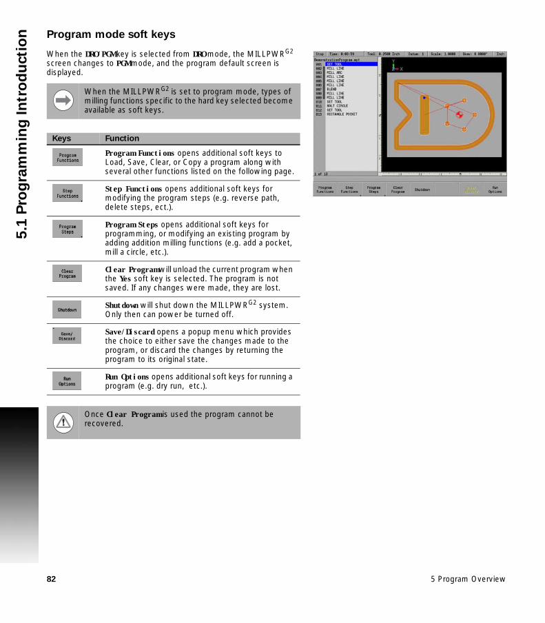
82 5 Program Overview
5.1
Pro
gra
mm
ing
In
tro
du
cti
on Program mode soft keys
When the DRO/PGM key is selected from DRO mode, the MILLPWRG2 screen changes to PGM mode, and the program default screen is displayed.
When the MILLPWRG2 is set to program mode, types of milling functions specific to the hard key selected become available as soft keys.
Keys Function
Program Functions opens additional soft keys to Load, Save, Clear, or Copy a program along with several other functions listed on the following page.
Step Functions opens additional soft keys for modifying the program steps (e.g. reverse path, delete steps, ect.).
Program Steps opens additional soft keys for programming, or modifying an existing program by adding addition milling functions (e.g. add a pocket, mill a circle, etc.).
Clear Program will unload the current program when the Yes soft key is selected. The program is not saved. If any changes were made, they are lost.
Shutdown will shut down the MILLPWRG2 system. Only then can power be turned off.
Save/Discard opens a popup menu which provides the choice to either save the changes made to the program, or discard the changes by returning the program to its original state.
Run Options opens additional soft keys for running a program (e.g. dry run, etc.).
Once Clear Program is used the program cannot be recovered.

ACU-RITE MILLPWRG2 83
5.1
Pro
gra
mm
ing
In
tro
du
cti
onProgram functions
Program functions soft keys
The Program Functions soft key provides access to the following soft keys for saving, clearing, or loading an existing program to either edit or run.
Soft key Function
The Load soft key will load the selected program. If a program is currently loaded, a prompt will be displayed asking for confirmation to clear the loaded program. If a program is currently loaded, it must be saved prior to pressing this key.
The Save soft key will save the currently loaded program, or the program can be saved under a new program name.
The Program Type soft key opens a popup Menu providing the choices which type of programs to display in the folder listing; MILLPWRG2 programs, G-code programs, DXF drawings, All programs or All files.
The Function soft key opens a popup Menu providing the choices to Cut, Copy, Paste, Merge, Rename, or Delete any program that is listed in the folder. It does not need to be the currently loaded program.
The Select soft key allows the operator to select one or more programs from the current folder, or select all the programs. Select the Clear option to un-select the current selected program(s). This allows features within the Function soft key to be done on the selected group of programs.
The Change Window soft key toggles the cursor between the folder list window (1), folder tree window (2) (if displayed) and program list window (3).
The Folder View soft key opens the folder tree window to access all folders, and sub folders. Use the Change Window soft key to navigate to the available windows.
Press the Exit soft key to return to the Program Function screen.

84 5 Program Overview
5.1
Pro
gra
mm
ing
In
tro
du
cti
on Pressing the Select soft key feature opens a popup
menu that provides these three choices:
The Select feature will select one or more programs. Highlight each program to be selected, and choose Select for each program highlighted.
The Select All feature will select all programs in the folder.
The Clear feature will un-select one or more programs that have been highlighted. Clear does not delete a program, it will only un-select it.
Having a program, or programs selected, use the Function soft key to continue on taking the appropriate action required.
The Function soft key provides several choices that can be executed for the action taken after using the Select soft key feature:
The selected program(s) can be Cut from the current folder, then moved to another folder using the Paste feature.
In the same fashion, using the Copy feature, the selected program(s) can be copied to the same folder, or to a different folder using the Paste feature.
Use the Merge feature to paste the contents from the selected program to the currently loaded program at the current cursor location. This feature is only available for MILLPWRG2 (.MPT) programs. Once this function is executed, it will exit the program functions, and return to program view.
Use the Rename feature to rename the selected program. Only one program at a time can be selected to use this feature.
Choosing the Delete feature will delete one or more programs selected. The message bar will be displayed showing the first selected program asking for confirmation to delete it. Four soft keys are displayed for deleting options.
Yes will delete the current program displayed in the message bar. Cancel will cancel out of the current operation. Cancel will not
restore any prior deletions that had been made. All will delete all the selected programs by automatically
answering yes to confirm deletion of each program. No will cancel the deletion of the current program in the message
bar.
Located in the upper right folder display area are two soft keys Forward (+), Backward (-). These keys can be accessed directly when using a mouse. Direct console access is accomplished by using the Plus, and Minus keys on the console keypad. The keys are used to facilitate navigation among folders in the console, network and USB memory devices.

ACU-RITE MILLPWRG2 85
5.1
Pro
gra
mm
ing
In
tro
du
cti
on Pressing the Minus key always takes you back to the previous folder
location. Pressing the Plus key takes you to the next folder in the history. Plus is only available if Minus has been used.
Recycle Bin
The Recycle Bin stores deleted files and can also be accessed to restore the deleted files to their original location.
Accessing the Recycle Bin:
Press DRO/PGM to activate program editing mode Press the Program Functions soft key Enable Folder View Select the Recycle Bin in the Folder Tree window
The MILLPWRG2 will save 20 history steps. The 21st history step will replace the 1st history step.
Edits to a program that have not been saved are lost.
The Recycle Bin may take 1-2 seconds to refresh and display its contents.
Soft key Function
The Empty Recycle Bin soft key will permanently delete all files in the Recycle Bin.
The Restore File soft key will restore the selected file(s) to the original location. This location will be displayed in the status bar.
The Delete File soft key will permanently delete the selected file(s) in the Recycle Bin.
Deleting a folder will move its contents into the Recycle Bin as separate files and not as a directory itself.
Files which were deleted from a removable drive will be restored to USB0: if it is present, otherwise they will be restored to V:\user\_Recovered\.
The Program Type filtering will automatically change to "All Files" when entering the Recycle Bin, and revert back when exiting Recycle Bin.

86 5 Program Overview
5.1
Pro
gra
mm
ing
In
tro
du
cti
on Enabling/Disabling the Recycle Bin
The Recycle Bin can be enabled or disabled through the Install Setup soft key. Change the parameters in the Advanced Cofiguration in “System -> CfgRecycleBin.” For additional information, see Installation Setup in Section 10.1.
Size of the Recycle Bin:
The Recycle Bin can store up to 500 MB of data. If the Recycle Bin reaches its maximum storage capacity prior to or while deleting a file(s), a prompt will provide the option to either permanently delete the file(s) or cancel the delete operation for the remaining files.

ACU-RITE MILLPWRG2 87
5.1
Pro
gra
mm
ing
In
tro
du
cti
onView hard key
While in PGM mode or running a program, pressing the VIEW key opens the View Setup dialogue. Several adjustment and graphical display options can be set here. To save changes, press the VIEW or USE key. Pressing the CANCEL key rejects the changes made and restores the graphics view to the previous state.
For drop down menus, use the RIGHT ARROW key to open, the LEFT ARROW key to close, and the UP or DOWN ARROW key to make a menu selection from the list.
All settings, except Adjust View and Simulation Speed, will remain until changed again. This also applies to system reboots and software updates.
For proper simulation when Show Model is active, make sure that tools are defined in the program and have a non-zero diameter. When the Markers feature is ON, a drill marker corresponding to the diameter of the tool will be displayed. Each tool with a unique diameter will be assigned a different color which will be used to display the material it removes so that it is clearly visible which tool removed which areas of block material.Each tool with a unique diameter will be assigned a different color to be used for the material it removes, such that it is clearly visible which tool removed which areas of block material.
The following describes the View Setup dialogue soft keys and drop down menu options available.
View Setup
Features Features can be turned on and off and are graphical representations of the following:
Tool is the solid tool component, which represents the tool as it moves, and changes between the color blue when it is outside of the material and red while it is actively cutting material.
Rapids are the tool movements that are set at a rapid feed rate.
Contour is the geometry of the programmed contour.
Markers are the zero point marker, reference point markers, drill marker cross-hairs, and lines of reflection.
Edges are the blockform edge lines which outline the material in the X, Y, and Z axes.

88 5 Program Overview
5.1
Pro
gra
mm
ing
In
tro
du
cti
on
2D Grid In 2D views, an overlay grid can be used in conjunction with the edge ruler to aid with visual measurements within the graphic display.
Visible allows the grid to be turned on or off.
Spacing adjusts the amount of distance between the grid lines, and is relative to the actual part size.
Adjust View These three buttons allow you to adjust the graphic display.
Cursor to the appropriate button: Pan, Rotate, or Zoom then press the ENTER key to activate the adjustment mode. The button text will shift to the right side of the button to indicate that the adjustment mode is active. Use the Arrow keys to adjust the display.
Press ENTER or CANCEL to exit the active adjustment mode.
Simulation Speed The simulation speed can be changed to any of the following values:
Full: Simulates the program as fast as possible.
10X: Simulates the program at ten times the programmed feed rate.
5X: Simulates the program at five times the programmed feed rate.
Actual: Simulates the program at the programmed feed rate.
½X: Simulates the progr am at half the programmed feed rate.
Machining a part in PGM mode will show the soft keys to easily toggle between 2D or 3D, toggle the solid model on/off, toggle the tool path lines on/off, or reset the view to default, without having to open the View Setup dialogue.
View Setup

ACU-RITE MILLPWRG2 89
5.1
Pro
gra
mm
ing
In
tro
du
cti
onView setup soft keys
The following soft keys are always available while the View Setup dialogue is open. Additional soft keys are also made available dynamically depending on which setting is active in the dialogue.
Soft key Function
The 2D/3D soft key toggles the graphic display between a two-dimensional and three-dimensional view.
The Show Model soft key displays or hides the solid model rendering in the graphic display.
The Show Toolpath soft key displays or hides the rapid and feed toolpath lines in the graphic display.
The Redraw soft key re-runs the program simulation and update graphic display. If the program is currently mid-simulation, it will be cancelled. The decimal “.” key is a shortcut to achieve this same behavior even when the View Setup dialogue is not open.
The Block Form soft key displays the Block Form dialogue, which shows the minimum and maximum dimensions of the material block form of the part. The values can be overridden in this dialogue to match the actual block of material being used if desired, and can be saved by pressing USE.
The Reset Graphics soft key restores the graphic display adjustments to the default values. The Pan, Zoom, and Rotate adjustments will be reset.

90 5 Program Overview
5.1
Pro
gra
mm
ing
In
tro
du
cti
on Step functions soft keys
The Step Functions soft key provides access to the following soft keys for assistance with programing steps, and modifying or arranging the programs steps.
Soft key Function
The Explode soft key will explode a program step e.g. such as a bolt circle converting it from a radius and number of holes equally spaced to individual coordinates for each hole. See "Explode" on page 192 for additional information.
The Reverse Step soft key will reverse the tool path of the selected step so that it will be followed in the reverse order.
The Reverse Path soft key will reverse the tool path selected of all the steps so that it will be followed in the reverse order.
The purpose of the Shift/Rotate Steps feature is to transpose a range of steps from one location to another on the actual work piece within a program.
The Change Steps soft key opens a dialogue that will allow the operator to select a range of steps that can be modified for the Z axis, Offset, and Feed Rate.
The Delete Steps soft key opens a dialogue that will allow the operator to select a range of steps, or a step to be deleted.
The Copy / Move Steps soft key opens a dialogue that will allow the operator to select a range of steps to either be copied, or moved else where in the program.
Machining a part in PGM mode will show the soft keys to easily select between 2D Line, 3D Line and 3D Solid without having to open the View Setup dialogue.

ACU-RITE MILLPWRG2 91
5.1
Pro
gra
mm
ing
In
tro
du
cti
onProgram steps soft keys
The Program Steps soft key accesses the soft keys listed in the table below. Each soft key (except for the Tool key) provides additional selections on a popup menu. This allows to further define the milling action to be programmed.
Soft key Function
The Tool soft key opens a tool dialogue to enter the size and type of tool to be used for the following step(s).
The Position/Milling soft key opens a popup menu to further define the milling operation e.g. Position/Drill, Line, Arc, Blend (Arc), Blend (Chamfer), and Contour.
The Custom Pocket soft key opens a popup menu to further define the milling operation e.g. Custom Pocket, Island, Pilot Drill, Rough Mill, Bottom Finish, and Side Finish.
The Hole Pattern soft key opens a popup menu to further define the milling operation e.g. Row of Holes, Rectangle Frame, Rectangle Array, and Bolt Circle.
The Rectangle soft key opens a popup menu to further define the type of milling operation e.g. Pocket, Frame, Face, and Slot.
The Circle soft key opens a popup menu to further define a milling operation e.g. Pocket, Frame, Ring, Helix, and Slot.
The Repeat, Rotate ... soft key opens a popup menu to further define a milling operation e.g. Repeat, Rotate, or Mirror
The Other Steps soft key opens a popup menu to further define the type of milling operation e.g. Engrave Line, Engrave Arc, Comment, Auxiliary Function, Dwell, or Reference Point.

92 5 Program Overview
5.1
Pro
gra
mm
ing
In
tro
du
cti
on Clear program soft key
This soft key provides a quick method to clear the current loaded program. It does not provide an option to save before exiting. Its function is meant to quickly clear a program (e.g. once it has been run and is no longer needed), so that a new program can be loaded, or a blank program is available, or return to DRO mode without having a program loaded. If the program has been edited the operator is asked to confirm the Clear operation. Save program changes before using Clear. All changes are lost and cannot be recovered.
Press the Clear Program soft key to close the program.
Save/discard soft key
Save/Discard soft key opens a popup menu which provides the choice to either save the changes made to a program, or discard the changes by returning the program to its original state.
Press the Save/Discard soft key and select from the popup menu to either save the program, or discard the changes made to the program.

ACU-RITE MILLPWRG2 93
5.1
Pro
gra
mm
ing
In
tro
du
cti
onRun options soft keys
The Run Options soft key allows the program to be run and tested with various options for a program. These options allow the operator to test a program without actually cutting material. The Run Options must be set before you start to run the program.
Soft key Function
The Single Step soft key will move the machine one step at a time.
The Dry Run soft key will run the program’s tool path at the speed defined in Job Setup. No material should be placed within the tool path for this function. Dry Run is intended to provide a quick verification of the machine movements in the program.
The Graphics Only soft key will run the program’s tool path without activating the servo motors. The graphics and DRO display shows the progress of the program without motion or AMI output. Graphics Only previews the tool path at programmed speed without the risk of tool or part damage.
The Optional Stop soft key will allow the program to be stopped at different locations to allow for verification of particular program steps selected has the operator. If a program has an optional stop (i.e.: M01 in a G-code program), the system will only stop at this block when Optional Stop is enabled. If it is disabled, it will be skipped. The Optional Stop is an M01 in a G-code program.
The Look Ahead soft key will detect when programmed features with an offset are too small for the current tool radius and adjusts the path as needed.
The Exit soft key will exit the Run Options function and return to the previous display.

94 5 Program Overview
5.1
Pro
gra
mm
ing
In
tro
du
cti
on Program saving
When you create programs with the MILLPWRG2, they can be saved within MILLPWRG2's User folder, on a USB device, or a network location.
MILLPWRG2 will retain a program in memory so it is not lost in the case of a power failure.
Programs can be organized in MILLPWRG2, on a USB device, or a network location; or in personalized folders that the operator can create.
Saving a program
A new blank program can be saved prior to having any program steps added, a newly created set of program steps can be saved as a new program, or an existing program can either be saved as a new program by replacing the current name, or save the existing program.
To save the current active program, select the Save soft key. The keyboard will popup with the Save key highlighted. Press the ENTER key. A prompt will ask to overwrite the existing program. Press the Yes softkey.
The keyboard will automatically be displayed with the current program name highlighted in the keyboard display window (see "Keyboard" on page 39).
The Save/Discard key is also available to quickly save a program, or discard any changes made since the last time it was saved.
Press the Save/Create soft key to save the program with its current name, or enter a new name for the current program to create a new program.
A name can not be longer than 60 alphanumeric characters. The MILLPWRG2 displays program names as they were entered. No two programs can have the same name.
The program’s graphic preview is updated whenever the program is saved. In order for the new graphic preview to be created correctly, the program must not have any errors. The operator must allow the program graphics to finish drawing the program before pressing any keys.

ACU-RITE MILLPWRG2 95
5.2
Pro
gra
m M
od
e F
un
cti
on
s5.2 Program Mode Functions
Program type filter
In PGM mode, press the Program Functions soft key to display the Folder View, and Program Type soft keys. Program type aids with locating programs by type, and reduces the number of programs that are displayed.
To select what type of programs to show, press the Program Type soft key, and select which program type(s) to display using the ARROW keys.
USB access
As soon as the USB memory device is inserted, its contents will be displayed in the Folder Contents window. From here the operator can modify, copy, delete, etc. any of the programs, or folders on the USB device.
In PGM mode, the operator can access a USB memory device by inserting the USB device into a USB port of the MILLPWRG2.
From DRO mode, press the DRO/PGM to enter PGM mode. Press the Program Functions soft key. Press the Folder View soft key.
The display will now show the USB device in the Folder Contents window, and when selected, will show its content in the upper right window.
It is recommended to copy programs from the USB device to the user folder and use the program from the MILLPWRG2.
Prior to removing the USB memory device, check that the activity indicator light on the USB drive is not active or blinking. This will ensure that all commanded disk operations have completed, and that it is now safe to remove the drive.

96 5 Program Overview
5.3
Cre
ati
ng
Pro
gra
ms O
ve
rvie
w 5.3 Creating Programs Overview
New part program
The following briefly describes how a new program is created. See "Fundamentals for Creating a Program" on page 101 for more complete information.
Press the DRO/PGM key from DRO mode to enter PGM mode.
A new program can be created from an existing program, or create a completely new program.
To create a new program from an existing program:
Press the Program Functions soft key. Select an existing program that will be used to create the new
program, and press the Load soft key. Press the Program Functions soft key. Press the Save soft key. Press the Keyboard soft key to display the
keyboard if the keyboard is not automatically displayed. Type in the name of the new program and select Save.
The new program is now loaded, and can be modified as required.
To create a new (blank) program:
When a program is currently loaded, press the Clear Program soft key in the PGM mode display to clear the loaded program from memory, and to create a new program.
Press the Save soft key. Press the Keyboard soft key to display the keyboard if the keyboard is not automatically displayed. Type in the name of the new program and select Save.

106
Programming

98 6 Programming
6.1
Co
nve
rsa
tio
na
l P
rog
ram
min
g 6.1 Conversational Programming
Programming considerations
“From” and “To” points
Lines and arcs are defined by their From point (the point where they begin) and To point (the point where they end).
Depth of cut
When programming the depth of cut, MILLPWRG2 will prompt for the Begin and End locations for the Z axis.
The location that is entered into the Z Begin field tells MILLPWRG2 where the quill is to begin cutting at the programmed feed rate. The End location defines the depth of the cut.
Pass
Pass refers to the number of cuts or the distance (depth) of each cut that are used to machine an area to its End depth. The operator selects which is to be required in this field from Job Setup. In the Job Setup dialogue, Distance or Number of Cycles must be selected. Which selection is chosen will appear on all dialogues where it is required. The number of passes can be controlled by entering a value in the Pass field (where ever it is available).
Always be sure that the Begin location is above the surface of the workpiece.
Pass is ignored on 2 axes systems. The operator must set the depth of cut for each pass, and repeat the operation until the full depth has been reached (see "Machining your part" on page 116).
Leaving the field blank programs the MILLPWRG2 to make the cut in the number of passes it decides is necessary. No pass will exceed the diameter of the active tool

ACU-RITE MILLPWRG2 99
6.1
Co
nve
rsa
tio
na
l P
rog
ram
min
gTool offset
MILLPWRG2 will calculate the actual tool path when using left and right offsets. Program the dimensions of the part as identified by the part drawing.
Program a line, arc, frame, etc. using the “Tool Offset” field to tell MILLPWRG2 which side of the line the tool is to be on. See "Tool radius offset" .
To determine which offset to use: If the tool needs to be on the left side of the line, use a Left offset. If the tool needs to be on the right side of the line, use a Right offset.
When using a Center offset, the programmed dimensions are for the center of the tool. For some milling functions, like frame and arc, Inside and Outside offsets are available to make it easier to define the tool offset.
Datum selection
The datum is where workpiece (absolute) zero is located. See "Steps to establish the datum" .
If the datum isn't defined on your print, then determine the datum based upon where most of the dimensions originate.
Pick a point which will let you enter most of the dimensions directly, with fewest calculations.
Establishing a datum requires that the Z retract position be provided (the position the quill returns to between program steps).
By setting a retract position, you can ensure that the tool you are using does not make contact with your workpiece when the quill moves from one position to the next.
Establish a retract position for the Z axis each time the console is powered, otherwise the MILLPWRG2 will use the quill’s previous retract position.
A two axes system also requires the Z depth, and Z retract position. The operator will be prompted to manually move to a depth, or retract position.

100 6 Programming
6.1
Co
nve
rsa
tio
na
l P
rog
ram
min
g Absolute vs. incremental dimensions
MILLPWRG2 allows both absolute and incremental dimensions to be entered. A dimension measured from the point you defined as datum is an absolute dimension. A dimension measured from any other point is an incremental dimension. See “Absolute and incremental work piece positions” on page 47..
The dimension moves of 8, then 8 again are incremental moves. The dimension moves of 8, then 16 are absolute moves.
Continuous milling
When you program a continuous contour of lines and/or arcs the contour will cut without stopping if there is no programmed stop. MILLPWRG2 will automatically recognize continuous contours as you're programming. There are no special key presses or other functions to learn.
For lines and arcs to be continuous, they must:
Be consecutive steps in a program.Have the same depth.Be cut with the same tool.Be cut using the same tool offset. Share a common “From” or “To” point (one step must end at the
point where the next one begins).
If one step follows another, then MILLPWRG2 assumes that they are to be connected (see steps 003 through 006). The single line bracket indicates the steps that will be machined with continuous milling.
MILLPWRG2 automatically fills in the From point, Depth, and Tool Offset from the previous step. The To point must be filled in, and then press the USE key.
Different feed rates within each step of a continuous contour are allowed, and can be used.

ACU-RITE MILLPWRG2 101
6.1
Co
nve
rsa
tio
na
l P
rog
ram
min
gFundamentals for Creating a Program
In DRO mode press the DRO/PGM key to enter program mode.
Programs are created by developing a list of milling steps to be performed. As steps are added to the list, each will immediately be drawn on the screen so that it can be displayed graphically, showing the part machining in progress.
Entering milling steps
Before any programming steps are entered, a tool must first be selected and entered. See “Editing the tool table” on page 70..
The milling function keys are among the eight yellow keys located in the upper right corner of the console. The function you select will appear in the program listing and will enable you to enter the data and add the step into the program.
Additional milling functions are available in PGM mode, and are accessed by pressing the Program Steps soft key. Program Steps soft keys are also displayed when RECT, CIRCLE, or the HOLES keys are pressed in PGM mode.
To enter a milling step, press the appropriate milling function (e.g. LINE). Some keys will open a popup menu with the soft key to further define the type of milling step that is to be performed.
After entering the data for the program step, press the USE key to add the step to the program.
Press the CANCEL key at anytime to exit the milling step dialogue and not add it to the program.
MILLPWRG2 allows a maximum of 9999 program steps.

102 6 Programming
6.1
Co
nve
rsa
tio
na
l P
rog
ram
min
g Adding/inserting milling steps
A new program step number automatically appears following the last step entered, and the new step is highlighted.
If the cursor was moved for any reason, use the ARROW keys to highlight the new step, then select the milling function to be added.
To insert a step between two existing steps, position the cursor to the step below where the new step is to be placed.
Press the desired milling function key, and it will be inserted above the highlighted program step.
Additional milling functions are available by pressing the Program Steps soft key. The soft keys change, displaying several Milling function soft keys. Each soft key when selected will have a popup menu for further selection to refine the type of milling operation to be entered. For example, the Circle soft key will display choices for the type of circle to be milled; a Pocket, Frame, Ring, or a Helix.
Editing or deleting a milling step
To edit a program step, use the ARROW keys to highlight the step to be changed and press the USE or ENTER key, or just enter a step number using the numeric keypad.
A Goto program line number popup dialogue is immediately displayed. The total number of lines in the program are shown in the Line Count: field.
Enter the desired line number and press ENTER. Press ENTER or USE again to edit the program step.
After making the appropriate changes, press the USE key to accept the changes and place the step back into the program. Or press CANCEL to discard any changes to the step.
To delete a step, highlight the step to be deleted, then press the CLEAR key.
VIEW key
If you need to see the machined part in more or less graphic detail, press the VIEW key. This enables you to access the viewing soft keys that are available. See "View hard key" for a complete description of these soft keys.

ACU-RITE MILLPWRG2 103
6.1
Co
nve
rsa
tio
na
l P
rog
ram
min
gProgram errors
When an error is detected in a program, the step with the error is highlighted in the program listing with a red "x" symbol. Edit the program step to correct the error.
Additional information about the error is added to the message log. See "Message log" .
Program edited
When a saved program is loaded, only the name and extension is displayed.
If the saved program is then edited, the program name will show an asterisk at the end of the name.
This tells the operator that the program has changed, but has not been saved.
Saving the program will remove the asterisk, or exit the program without saving the changes.
When a program that has been edited, but not saved, then it will revert back to the last saved version when closed. The program will not display an asterisk the next time it is loaded.
After correcting the errors, remember to clear them from the message log. A quick method for clearing all errors in the log is to press the “0” on the numeric keypad.
If there is more than one error in the program, only the first step with an error will be highlighted. After correcting the first error, the next error will be highlighted.

104 6 Programming
6.1
Co
nve
rsa
tio
na
l P
rog
ram
min
g Step Form Validation
Once a step has been programed in the program dialogue and the USE key has been pressed, if further data is required, that field will display a red x.
Once a step has been programed in the program dialogue and the USE key has been pressed, if the data in any field has been entered incorrectly, that field will display a yellow warning symbol.
Correct any errors or warnings before proceeding.

ACU-RITE MILLPWRG2 105
6.1
Co
nve
rsa
tio
na
l P
rog
ram
min
gRunning a Program
Skewing a part
With MILLPWRG2, it may save time setting up a job by skewing the part. The Skew feature automatically compensates for the offset angle of the part by touching off one straight edge with an electronic edge finder or a mechanical indicator.
To skew a part touch off on two or more points along one axis, either X or Y. Touch off and use the teach position feature.
A work piece that has a rough edge should have multiple points entered along the straightest edge to more accurately calculate the skew angle.
For some machining operations it is more convenient to use the Skew feature rather than indicating in the work piece.
Do not enter coordinates along a curve, two different lines, or along a line that’s positioned at a 45 degree angle. MILLPWRG2 will calculate the skew angle based upon a straight line between the points that have been entered.

106 6 Programming
6.1
Co
nve
rsa
tio
na
l P
rog
ram
min
g Setting the skew angle with an electronic edge finder:
Press the Datum softkey to open the DATUM dialogue. Highlight the Angle field.
Press the Probe soft key.
Touch off on two or more points along any single straight edge of your part. You’ll notice that the Angle and Points fields change as you enter points.
Press the Finish soft key. Press the USE soft key to accept all of the points and return to the
DRO screen. Press CANCEL to return to the DRO screen without accepting any points or affecting your previous skew angle.
The Clear Angle soft key will reset the Angle, and the Points fields to zero.
Using teach:
Move the table so that a mechanical indicator rests against any straight edge on the part. Press the Teach soft key to enter your coordinate.You’ll notice that the Points change.
Now move the table so that the mechanical indicator touches another point on the same straight edge. Press the Teach soft key. You’ll notice that the Angle and Points fields change.
Repeat this process for any additional points.
Press the USE soft key to accept all of the points and return to the DRO screen. Press CANCEL to return to the DRO screen without accepting any points or affecting your previous skew angle.

ACU-RITE MILLPWRG2 107
6.1
Co
nve
rsa
tio
na
l P
rog
ram
min
gEstablishing a datum
Overview
Datum is the workpiece zero or absolute zero, and is a point of reference that the MILLPWRG2 bases all of the part's coordinates from.
A datum must be established for every job. Datum's location may be indicated on the print; or the operator may establish a datum that allows most of the part's dimensions be entered directly using the least amount of calculations.
When establishing datum, it may be easiest to locate a known point on each axis, such as the corner of the part, or a location on a vise or fixture.
Datum can be set at a point on the top surface, a position beneath the surface, or at a point where there's no material present (such as in the center of a circular part). The following example will illustrate touching off the edge of a work piece using a tool, but an edge finder can also be used in place of the tool. Either item will accomplish the same result.
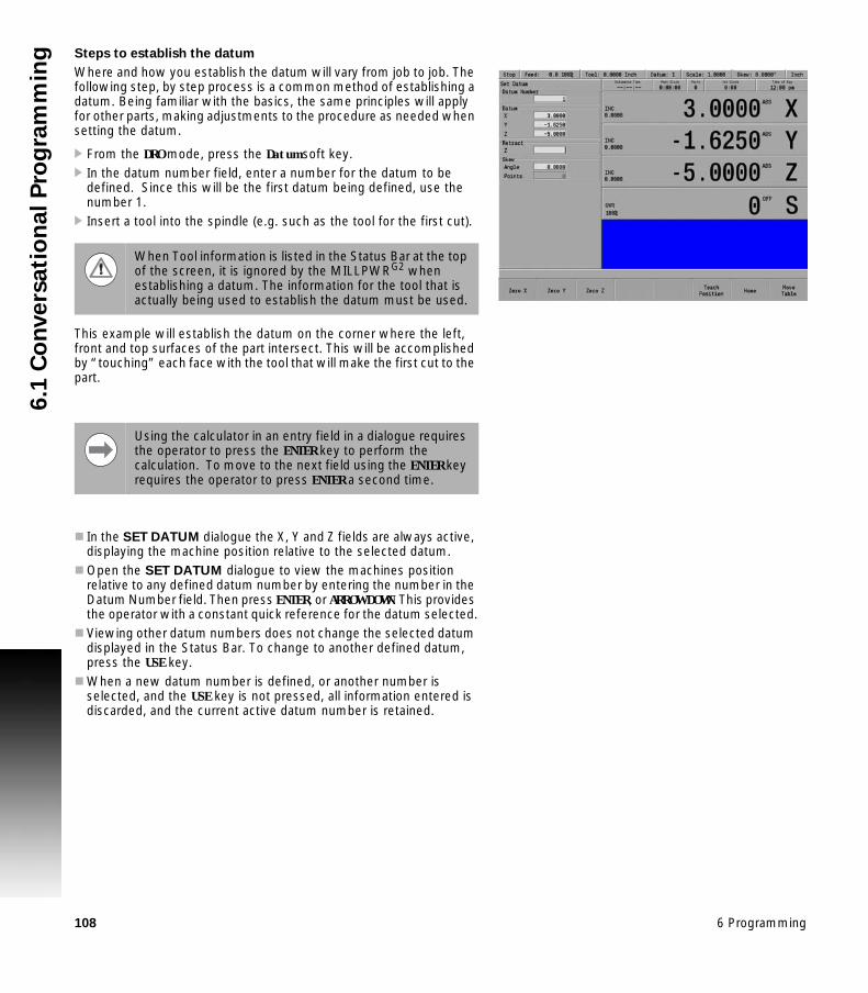
108 6 Programming
6.1
Co
nve
rsa
tio
na
l P
rog
ram
min
g Steps to establish the datum
Where and how you establish the datum will vary from job to job. The following step, by step process is a common method of establishing a datum. Being familiar with the basics, the same principles will apply for other parts, making adjustments to the procedure as needed when setting the datum.
From the DRO mode, press the Datum soft key. In the datum number field, enter a number for the datum to be
defined. Since this will be the first datum being defined, use the number 1.
Insert a tool into the spindle (e.g. such as the tool for the first cut).
This example will establish the datum on the corner where the left, front and top surfaces of the part intersect. This will be accomplished by “touching” each face with the tool that will make the first cut to the part.
In the SET DATUM dialogue the X, Y and Z fields are always active, displaying the machine position relative to the selected datum.
Open the SET DATUM dialogue to view the machines position relative to any defined datum number by entering the number in the Datum Number field. Then press ENTER, or ARROW DOWN. This provides the operator with a constant quick reference for the datum selected.
Viewing other datum numbers does not change the selected datum displayed in the Status Bar. To change to another defined datum, press the USE key.
When a new datum number is defined, or another number is selected, and the USE key is not pressed, all information entered is discarded, and the current active datum number is retained.
When Tool information is listed in the Status Bar at the top of the screen, it is ignored by the MILLPWRG2 when establishing a datum. The information for the tool that is actually being used to establish the datum must be used.
Using the calculator in an entry field in a dialogue requires the operator to press the ENTER key to perform the calculation. To move to the next field using the ENTER key requires the operator to press ENTER a second time.

ACU-RITE MILLPWRG2 109
6.1
Co
nve
rsa
tio
na
l P
rog
ram
min
gX axis datum
Lower the tip of the tool so that it falls below the top surface of the part.
Move the table along the X axis, slowly spinning the tool by hand as you go. When the tool contacts the part, stop the table.
Using the numerical keypad, enter the radius of the tool (the distance from the center of the tool to the edge of your part) into the X: field. Be sure to specify if it’s a negative value.
Press the +/- key. Enter the radius value. Press the ENTER key to enter the data and move to the next field.
Y axis datum
Lower the tip of the tool so that it falls below the top surface of the part as done with the X axis.
Move the table along the Y axis, slowly spinning the tool by hand as you go. When the tool contacts the part, stop the table.
Using the numerical keypad, enter the radius of the tool (the distance from the center of the tool to the edge of your part) into the Y: field.
Press the +/- key to change the data to a negative value. Enter the radius value. Press the ENTER key to enter the data and move to the next field.
Z axis datum
Position the tool so that its tip touches the top surface of the part. Press the Z = 0 soft key. Press the ENTER key. With the data entered, the cursor will highlight
the next field.
In this example, the value will be specified as a negative value, because the tool's center is on the negative side of our datum (refer to Axis Conventions).
When changing the state of W axis coupling (knee coupled to quill) to enable or disable it, this can result in invalid Z axis datum points. After changing the coupling state, always re-establish any Z axis datum points to ensure correct positioning.

110 6 Programming
6.1
Co
nve
rsa
tio
na
l P
rog
ram
min
g Retract Z
Now either enter the Z axis retract position (the position that the quill should return to between steps) which is the location above the top surface of your part.
Or press the CLEAR key to clear the value. If no value is set, the quill will retract to the upper software travel limit between steps.
Or press the Teach Position soft key to use the current quill position as the retract location. Be aware that the quill will retract to this location regardless of the tool's length or the Z datum location.
Press the ENTER or USE Key to save the datum location and return to DRO mode.
Datum and the Z axis retract position have now been established.
Using an electronic edge finder
When the Set Datum dialogue is first opened, the Datum Number field is highlighted. Enter a new datum number, or select a number that is to be modified.
When a Datum field is selected (X, Y or Z), the Probe softkey is enabled. This allows the operator to set the datum using an electronic edge finder.
Each datum has its own retract position. When a new datum is selected, that datum’s retract position will be used.
Setting the datum on any axis will zero that axis’s INC display.
When the probe key is selected, the electronic edge finder is automatically selected. The radius of the tip must first be entered into the Job Setup dialogue.

ACU-RITE MILLPWRG2 111
6.1
Co
nve
rsa
tio
na
l P
rog
ram
min
g Select the datum field that is to be set (X, Y or Z axes), then press the Probe soft key.
The datum is set for the axis that was last used when the edge finder was triggered. If moving the X axis when the edge finder is triggered, the X datum will be set and the X datum field will be set to 0.0000.
With the Probe soft key activated, select the type of probing to be performed by pressing the appropriate softkey: Edge, Centerline, or Circle Center.
Setting the datum on an edge
The coordinates of the datum can be set by probing edges or surfaces and capturing them as datum, either in the X or Y direction.
Press the Probe soft key. Press the Edge soft key. The message Move to edge appears in the
message bar.
Move the edge finder until it makes contact with the work piece edge, and the Move to edge message disappears.
Retract the edge finder from the work piece.
The diameter of the edge finder and direction of motion will set the location of the datum to the work piece edge.
To set the edge to a specific value, add or subtract an offset to the datum coordinate. For example, to have X = 3.0; press the +(PLUS), 3, and ENTER hard keys.
Keys Function
Edge sets the datum with a single trigger of the edge finder. The system will prompt to "Move to edge". Using any axis, start movement until the edge finder is triggered. Once triggered, the system will exit the probing mode and set the moving axis' datum.
Centerline sets the datum with 2 triggers of the edge finder and will use the center point as the axis' datum. The axis that is used for the first trigger must be used for the second. For example, if the first trigger occurred using the X axis, the X axis must be used for the second trigger.
Circle Center sets the datum using 3 points of a circle. This operation will only work with the X and Y axis and any of the triggers can be accomplished by moving either of these axes. This function will set the datum for both X and Y.

112 6 Programming
6.1
Co
nve
rsa
tio
na
l P
rog
ram
min
g Setting the datum at the centerline
The position of the centerline is determined by probing two edges, either in the X or Y direction.
Press the Probe soft key. Press the Centerline soft key. The message Move to first edge
appears in the message bar.
Move the edge finder until it makes contact with the work piece edge, and the message changes to Move to second edge.
Move the edge finder towards the second edge of the work piece until it makes contact, and the Move to second edge message disappears.
Retract the edge finder from the work piece
The diameter of the edge finder and direction of motion are used to set the datum at the midpoint between the two edges.
To set the midpoint to a specific value, add or subtract an offset to the datum coordinate. For example, to have X = 1.5; press the +(PLUS), 1, •, 5, and ENTER hard keys.
Setting the datum at the center of a circle
The center of a circular feature is determined by probing 3 edges around the circle in the X and Y direction.
Press the Probe soft key. Press the Circle Center soft key. The message Move to first edge
appears in the message bar.
Move the edge finder towards a point on the circumference until it makes contact. The message changes to Move to second edge.
Probe two additional points on the circumference in the same manner.
The datum is now located at the center of the circle.
To set the center to a specific value, add or subtract an offset to the datum coordinate. For example, to have X = 1.5; press the +(PLUS), 1,•,5, and ENTER hard keys.

ACU-RITE MILLPWRG2 113
6.1
Co
nve
rsa
tio
na
l P
rog
ram
min
gTest the datum setting
It's recommended to test the datum setting before beginning a program.
To confirm the datum setting use the Pos key. To quickly move to the datum for X and Y, press the Pos key. With the Z axis at its retract position, enter 0.0000 for the go to
position for both the X and Y (leave the Z field blank). Press the GO key.
The table will move to the datum position X 0.0000, Y 0.0000.
Lower the tool until it touches the part. Visually check the tool's position. The lower left corner of the part
should be positioned directly beneath the center point of the tool. The readout screen should be at 0.0000, confirming the datum is
accurate and programming can now begin.
The value of 0.0000 in the Z axis display may vary slightly depending on how the tool tip contacts the top surface of the part on the corner edge.

114 6 Programming
6.1
Co
nve
rsa
tio
na
l P
rog
ram
min
g Testing a MILLPWRG2 program
Before machining a part, test the program for things like correct tool path, count direction, feed rate, and sequence of operations. MILLPWRG2 provides several run-time choices to assist doing this. Always verify a program when it was loaded, or edited.
From the PGM screen, press Run Options to display the following soft keys:
Press any soft key to activate the option; press it again to deactivate it.
Whenever a program is about to run, check that the handles are recessed.
Keys Function
Single Step runs through the program one step at a time. Some steps will run as a single group such as a contour, or custom pocket.
Dry Run runs through the program at the defined dry run feedrate instead of programmed feeds. This option is useful to more quickly test the tool path motion. The dry run feedrate is set in the JOB SETUP dialogue.
The Graphics Only soft key will run the program’s tool path without activating the servo motors or AMI outputs. Begin from any step in the program. Use the graphics and DRO display to observe and verify the tool path.
The Optional Stop soft key will allow the program to be stopped at different locations to allow for verification of particular program steps selected by the operator. If a G-code program has an M01 (optional stop) in it, the system will only stop at this block when Optional Stop is enabled. If it is disabled, it will be skipped.
Before pressing the GO key to begin the Single Step or Dry Run features, check that the tool will not touch the workpiece when the quill begins to move. To avoid interference, do one or more of the following:
• Lower the knee
• Remove the tool or workpiece• Re-establish datum away from the part• Select Graphics Only run option

ACU-RITE MILLPWRG2 115
6.1
Co
nve
rsa
tio
na
l P
rog
ram
min
gSingle step
Normally, a continuous contour will be machined without stopping. With Single Step activated, MILLPWRG2 will stop after each step. This enables a check of the tool position of the Z axis relative to the part and ensure that the tool path and other program details are correct. Press the GO key to begin, and after each step finishes.
Dry run
With Dry Run activated, MILLPWRG2 will run the entire program at high speed without stopping. Visually follow the position of the tool relative to the part and ensure that the tool path and other program details are correct. This can be started at the beginning, or midway of a path. The dry run speed is defined in Job Setup. Press the GO key to begin.
Graphics only
With Graphics Only activated, MILLPWRG2 will run the entire program at programmed speed without activiting the servo motors or AMI outputs. Follow the position of the tool on the graphics or DRO display (ABS position only) to ensure the tool path and other program details are correct. This can be initiated at the beginning or midway through a path. Press the GO key to begin.
Skipping steps in a program
The option to temporarily skip one or more steps when running a program is available by pressing the +/- key. Navigate to the desired step and use the +/- key to skip the step without removing it from the program. The program runs as if the step is not present. Press the +/- key a second time to restore the step.
Move the cursor to the step to be skipped. Press +/- to skip or restore the step. A skipped step is grayed out
and an asterisk is placed before the step name.One or multiple steps may be skipped or restored by using the Change Steps dialogue which can be found under the Step Functions menu.
From the PGM screen, press the Step Functions key. Press the Change Steps soft key. Enter the first and last step numbers to be changed. Use the Arrow keys to navigate to the Skip Steps field. Select “Yes” to skip the steps or “No” to restore the steps. Press the Use key.
The Dry Run and Graphics Only run options may be combined at Dry Run speed without any table motion.
A step marked to be skipped cannot be edited. Restore the step before opening the step dialogue.

116 6 Programming
6.1
Co
nve
rsa
tio
na
l P
rog
ram
min
g Machining your part
Before running a program step, check the Status bar (located along the top of the MILLPWRG2 screen) to ensure that the tool identified by MILLPWRG2 matches the tool in the spindle. If there’s no tool identified, or if it’s incorrect, start with a Set Tool step that accurately identifies the tool that is to be used.
To move quickly to a step, use the UP or DOWN ARROW keys to highlight the required step, or just enter a step number using the numeric keypad. A Goto program line number popup dialogue is immediately displayed. The total number of lines in the program are shown in the Line Count: field.
Enter the desired line number and press ENTER. Press ENTER or USE again to edit the program step.
After highlighting the step to begin with, press the GO key. An Operator Intervention Message may ask to confirm that the tool is correct. Confirm that the correct tool is being used, then press the GO key again to begin milling.
If the tool is positioned above the Z axis retract position before running a program, the table will rapidly move to position, and then the quill will rapidly move to the retract position. If the tool is below the retract position, the quill will move first.
Once the quill has reached its retract position, it will rapidly move to the Begin depth then move at the programmed feed rate to the End depth.
If the upper software travel limit for the Z axis is set below the established retract position, a software travel limit fault will occur and the program will stop.
A 2 axes system requires that the quill be raised manually before pressing GO.
The remote STOP/GO switch acts as a pause switch if the table is moving, and as a GO switch if the machine is paused or stopped.

ACU-RITE MILLPWRG2 117
6.1
Co
nve
rsa
tio
na
l P
rog
ram
min
gMILLPWRG2 will automatically pause at points that require action to be taken (e.g., change tools). After each task has been completed, press the GO key.
If the STOP key is pressed once while cutting, the tool will pause in its cutting path and an Operator Intervention Message will appear. Press GO to resume machining, or STOP again to end the program.
Potentiometer for feedrate override
Feedrate Override are controlled with the potentiometer which will change the feed rate by a certain percentage with the knob rotation. The feed rate percentage will be displayed in the status bar at the top of the screen. A feed rate percentage of 100% means that actual feed rates will run at 100% of the programmed feed rates. If the feed rate percentage is 50%, actual feed rates will run at half of the programmed feed rates.
Adjustment of the feed rate with the potentiometer can be done at any time, even while the table or quill is moving.
A 2 axes system requires the Z axis to be moved manually into position.
If machining is started from the middle of a program, MILLPWRG2 will determine which tool should be used, and will prompt the operator to mount the tool if it is not mounted. It will also begin at the beginning of the current path.

118 6 Programming
6.1
Co
nve
rsa
tio
na
l P
rog
ram
min
g Manually positioning the quill
Programs that do not include a Begin depth will require the operator to manually position the Z axis during machining. The same is true when the Z axis has been disengaged during setup.
If an End depth is programmed, when it is time to manually position the Z axis, a preset value will be displayed in the Z axis display. The DRO screen will appear, along with the prompts shown.
An example of an Operator Intervention Message (OIM) similar to the one shown to the right will appear.
Manually move the Z axis incrementally until 0.0000 is displayed for the Z axis.
For additional information regarding 2 Axes operation see "Operating in 2 Axes and 3 Axes Modes" on page 31
When multiple passes are required, in this example the complete program can be run for each pass. It may also be necessary to repeat a set of steps for each pass in a program (e.g. milling a pocket).

ACU-RITE MILLPWRG2 119
6.2
Fo
lde
rs6.2 Folders
Folder functions
The soft keys available are described in the previous chapter, see "Program functions soft keys" on page 83.
MILLPWRG2 offers several versatile features for loading, saving, deleting, and backing up programs. Programs can be organized by creating folders. Folders can be quickly selected, created, make a backup copy, or if necessary, deleted.
Folders
Organize programs by saving them in folders. Folders may be used to group programs by job, operator, date, customer, or any other method preferred. Creating folders can only be done in PGM mode.
Creating a folder
First decide where to place the folder. It can be placed on V:\User which is the MILLPWRG2 folder in the console, on a USB device, on a network, or within sub-folders that have already been created. Use the following steps to create any type of folder, top level or sub level folders.
Press the Program Functions soft key, then press the Folder View soft key.
Press the Change Window soft key to select the Folder Tree window. Navigate through the folders to place the cursor where the new
folder is to be created by using the ARROW keys.
To expand a folder use the RIGHT ARROW key. To collapse an expanded folder, use the LEFT ARROW key.
Highlight the folder where the new sub-folder is to be placed, and press the Create Folder soft key.
When the Folder View soft key is activated, it remains active until it is pressed again to deactivate folder view.

120 6 Programming
6.2
Fo
lde
rs Naming a new folder
Using the on screen Keyboard, enter the name of the new folder. If the keyboard is not automatically displayed, press the Keyboard soft key.
Once the new folder’s name has been entered, press the Save/Create soft key to create the new folder.
Deleting a folder
MILLPWRG2 will delete folders that contain programs, or files. MILLPWRG2 will prompt the operator that there are files within the folder, and ask for confirmation if they are to be deleted.
Press the PROGRAM FUNCTIONS soft key, then press the Folder View soft key.
Press the Change Window soft key to select the Folder Tree window. Navigate through the folders, and place the cursor where the folder
is to be deleted. Press the Function soft key, and select Delete from the popup
menu. Press the Yes soft key to erase the folder, and all files in the folder,
or the No soft key to cancel.
Saving a program
When creating programs with the MILLPWRG2, they can be saved within MILLPWRG2's User folder, on a USB device, or to a network location. A graphic view of the program is displayed in the Preview Window if it has been run successfully.
Programs can be organized in MILLPWRG2, on a USB device, or a network location; or in personalized folders that the operator can create.
To save the current program for the first time:
Press the Program Functions soft key. Press the Save/Create soft key.
The keyboard should automatically be displayed with the cursor in the Program Name field (see "Keyboard" on page 39).
Once a folder is deleted it cannot be recovered.
ACU-RITE MILLPWRG2 121
6.2
Fo
lde
rsNaming a program
Before you can save a program, MILLPWRG2 requires it to be named.
Enter the program name using the ARROW keys to navigate the keyboard. Highlight the key to be used (e.g. letter, or number), then press the ENTER key to add the selection into the Program Name: Field. Continue in the same manner until the name is complete.
To add numbers to your program name, press any of the number keys on the numerical keypad, or from the keyboard display.
Press the Save/Create soft key. MILLPWRG2 will store the program in the folder that had been previously selected.
A message will alert you if the program was not saved properly, or if the name that you’ve chosen already exists.
Back up MILLPWRG2 programs regularly to avoid accidental loss (e.g. USB device, or to a network location).
Deleting a program
Press the Change Window soft key to select the Folder Contents window.
Highlight the desired program. Press the Function soft key, and select Delete from the popup
menu. Press the Yes soft key to erase the program, or the No soft key to
cancel.
Once a program is deleted it cannot be recovered.

122 6 Programming
6.2
Fo
lde
rs Loading a MILLPWRG2 (MPT) program
The Load soft key allows you to open programs in the folder listing. The steps below explain how to load a program from MILLPWRG2 User folder, a USB device, or from a network location.
If a program is loaded, save the open program, it does not have to be cleared.
From the PGM screen, press the Program Functions soft key. When a program is not located in the current folder, select the
location of the MILLPWRG2 program using the Folder View soft key, and Change Window soft key as needed.
Verify that MILLPWRG2 programs is selected in the Program Type popup menu. Only MILLPWRG2 programs stored in the selected folder will be displayed, see "Program type filter" on page 95.
Using the ARROW keys for navigation in the display window, highlight the MILLPWRG2 program to load.
Press the Load soft key, and verify that the desired program is now loaded.
When loading a program from a network, or a USB memory device, first select the device from the Folders Tree, then follow the same procedure as would be done from the MILLPWRG2 User folder.
Program extensions:MILLPWRG2 programs have a .mpt extension.G-code programs have a .G or .NC extension.DXF files must have a .DXF extension.
Use Folder View for locating folders, and programs to load.
It is recommended that all programs be copied to the local MILLPWRG2 User folder for usage.

ACU-RITE MILLPWRG2 123
6.2
Fo
lde
rsImporting a DXF drawing
Save any running programs. Locate the folder containing the DXF drawing.
If a program is loaded, save the open program, it does not have to be cleared.
From the PGM screen, press the Program Functions soft key. When a DXF drawing is not located in the current folder, select the
location of the DXF drawing using the Folder View soft key, and Change Window soft key as needed.
Verify that DXF Drawing is selected in the Program Type popup menu. Only DXF drawings stored in the selected folder will be displayed, see "Program type filter" on page 95.
Using the ARROW keys for navigation in the display window, highlight the DXF drawing to load.
Press the Load soft key, and verify that the desired program is now loaded.
MILLPWRG2 will assign default values for any information that’s missing from the DXF drawing (e.g. tool offset, feed rate, etc.). The required SET TOOL steps must be added.
MILLPWRG2 will then arrange the steps in a logical order based on common end points, and create a tool path. The program will then appear on the display.
Test the program before machining to ensure that the program steps and tool path do what is expected. The program can be edited and steps rearranged as needed.

124 6 Programming
6.2
Fo
lde
rs G-code programs
G-code editing capabilities
G-code programs have basic editing capabilities. The value of an existing g-code address can be changed.
There are no soft keys available for editing, all navigation is done using the ARROW keys. Use UP and DOWN ARROW keys to move the cursor to the line that needs to be edited. And press ENTER to edit the line.
Use the LEFT and RIGHT ARROW keys to move from address value to address value within the line. Enter the new value for an address. The UP and DOWN ARROW keys do not function in this mode.
Only the value of an address when highlighted can be changed. The CANCEL key will cancel any edits made. The ENTER key and the LEFT or RIGHT ARROW key accepts changes made to an address, and then moves to the next address. The USE key accepts the changes to the line and allows use of UP and DOWN ARROW keys.
The values of the following addresses can be edited: D, F, I, J, K, L, M, N, O, P, R, S, T, U, W, X, Y, and Z. See "G-code and M-Code definitions" starting on page 127.
A highlighted line can be removed by pressing the CLEAR key.
The MILLPWRG2 will calculate the block form of the G-code program. The values for the block form can be viewed using the Block Form soft key. The block form can be edited and even inserted into the program by using the soft key Insert G120. Once inserted in the program (G120), the block form in the program is used. Remove the line containing the G120 to revert back to the calculated block form.

ACU-RITE MILLPWRG2 125
6.2
Fo
lde
rsLoading a G-code program
MILLPWRG2 has the ability to read and run G-code programs. Basic editing is also possible. It is important to fully test the G-code program before machining a part.
A G-code program can be loaded into MILLPWRG2 in the same manner as MILLPWRG2 programs. Once loaded, MILLPWRG2 will indicate with an "x" the first error regardless of the cursor location. An error message also appears in the message line indicating that the line contains invalid code. The invalid code can be removed by editing the program outside of the MILLPWRG2.
The Load soft key opens programs that have already been saved. Use the following steps to load a G-code program from MILLPWRG2 User folder, a USB device, or from a network location.
If a program is loaded, save the open program, it does not have to be cleared.
When a G-code program is not located in the current folder, select the location of the G-code program using the Folder View soft key, and Change Window soft key as needed.
Verify that G-code programs is selected in the Program Type popup menu. Only G-code programs stored in the selected folder will be displayed, see "Program type filter" on page 95.
Using the ARROW keys for navigation in the display window, highlight the G-code program to load.
Press the Load soft key, and verify that the desired program is now loaded.
When loading a program from a network, or a USB memory device, first select the device from the directory tree and follow the same procedure as would be done from the MILLPWRG2 User folder.
Running a G-code program
MILLPWRG2 has the ability to read and run G-code programs. It is important to create and proof the G-code program before attempting to machine a part.
Verify the program in the CAD/CAM system that generated the program. MILLPWRG2 will draw the program when Loaded. Finally, lower the knee and dry run the program to verify that the tool path, feeds and speeds are correct.

126 6 Programming
6.2
Fo
lde
rs Using the tool table
Each "T" block refers to the corresponding number in the Tool Table. For example, T1 will cause MILLPWRG2 to retrieve the tool length offset from tool 1 of the Tool Table. MILLPWRG2 will then offset the spindle by this amount. T2 will cause MILLPWRG2 to retrieve the tool length offset from tool 2 of the Tool Table, etc. See chapter "4.1 Tool Table" on page 68 for a complete description about using the Tool Table.
It is very important not to have any tool length offsets in the Tool Table if the tooling is not repeatable. The user will need to set the Z datum after mounting the new tool. This is done before pressing GO to continue running the program.
Failure to maintain the Tool Table can cause unpredictable results. Verifying tool length offsets prior to program execution is strongly recommended.
Starting or stopping a G-code program Always start the program from a place in the program where the feed rate, X, Y, and Z axes position are known, such as a tool step. Alternate starting points can be programmed by placing the proper code in the desired locations.
Pressing the GO button will cause MILLPWRG2 to begin executing the G-code program. Always verify the program step highlighted is an appropriate starting point.
When a program is running, pressing the STOP button or the remote pendant will cause the program and all axis motion to pause. Pressing the remote pendant switch again or the GO button will cause the program to resume. Pressing the STOP button a second time will halt the program execution.

ACU-RITE MILLPWRG2 127
6.2
Fo
lde
rsG-code and M-Code definitions
G-code
The following is a list of supported, and unsupported G-codes. † Represents supported G-codes.
G-code listing
G-code Description Comment
G0 † Linear Interpolation (Rapid)
These commands generate table/quill motion. The motion command applies to current and subsequent blocks containing at least one X, Y, or Z coordinate. The default motion command is a linear move at feed (G1).
G1 † Linear Interpolation (Feed)
G2 † Circular Interpolation (CW)
G3 † Circular Interpolation (CCW)
G4 † DwellThis command causes the system to pause for the specified period of time. The period of time is determined by the P address (in milliseconds) or X address (in seconds). T Address also specifies the time in seconds.
G17 † XY Plane Selection
These commands set the plane in which arcs are executed. The setting applies to current and subsequent blocks. The default is G17 (XY).G18 † XZ Plane Selection
G19 † YZ Plane Selection
G20 † Set Program Units (INCH) Same functions as G70 and G71. These commands set the unit of measure. The setting applies to current and subsequent blocks. The default is G20 (INCH).G21 † Set Program Units (MM)

128 6 Programming
6.2
Fo
lde
rs G-code Description Comment
G28
Return to Home Reference
MILLPWRG2 does not have a method for establishing a “home” position. If one or more coordinates are specified in the block, the table/quill will rapid to that location. Program execution will continue with the next program block.G30
G40 † Cancel Cutter Compensation MILLPWRG2 supports automatic cutter compensation. Enable cutter compensation using G41 (left) or G42 (right). Disable compensation using G40 (center).G41 † Cutter Compensation (Left)
G42 † Cutter Compensation (Right)
G43 Tool Length Offset (+) MILLPWRG2 does not support tool length offsetting. The offset is retrieved from MILLPWRG2’s tool library when a tool change is executed. These commands are ignored.G44 Tool Length Offset (-)
G49 Cancel Tool Length
G54
Work Coordinate System
MILLPWRG2 does not support presettable work coordinate systems. G54 through G59 are ignored.
G55
G56
G57
G58
G59

ACU-RITE MILLPWRG2 129
6.2
Fo
lde
rsG-code Description Comment
G61 † Set “stop” Path ModeThese commands set the path mode. The setting applies to current and subsequent blocks. The default is G64 (continuous).
G64 † Set “continuous” Path Mode
G70 † Set Program Units (INCH) Same functions as G20 and G21. These commands set the unit of measure. The setting applies to current and subsequent blocks. The default is G70 (INCH). G71 † Set Program Units (MM)
G80 † Cancel Motion Mode This command cancels the current modal drilling cycle. The modal drilling cycles are described below (G80 series).
G81 † Basic Drill Cycle
Basic drilling cycle is generally used for center drilling or hole drilling that does not require a pecking motion. It feeds from the begin depth (R) to the specified hole depth (Z) at a given feedrate (F), then rapids to the retract height (P).
G81 Z(zDepth) R(zBegin) P(zRetract) F(feedrate)Required: Z(zDepth) and R(zBegin)
G82 † Counterbore Drill Cycle
Counterbore drill cycle generally used for counterboring. It feeds from the begin depth to Z depth, dwells for specified time, then rapids to the retract point.
G82 Z(zDepth) R(zBegin) P(zRetract) D(dwell) F(feedrate)Required: Z(zDepth), R(zBegin), and D(dwell)
G83 † Peck Drill Cycle
The peck drilling cycle is generally used for peck drilling relatively shallow holes. It feeds from the begin depth to the first peck depth (calculated so that all pecks are equal and do not exceed the maximum peck distance programmed in I word). Then rapid retracts to begin depth (to clear chip), rapids down to previous depth less .02", and continues this loop until it reaches the final hole depth. It then rapids to the retract point.
G83 Z(zDepth) R(zBegin) P(zRetract) I(zPeck) F(feedrate)Required: Z(zDepth), R(zBegin) and I(zPeck)
G85 † Boring Bidirectional Cycle
Boring Bidirectional is a boring cycle, generally used to make a pass in each direction on a bore or to tap with a self-reversing tapping head. It feeds from the begin depth to Z depth, and then feeds back to the retract height.
G85 Z(zDepth) R(zBegin) P(zRetract) D(dwell) F(feedrate)Required: Z(zDepth) R(zBegin)

130 6 Programming
6.2
Fo
lde
rs G-code Description Comment
G87 † Chip Break Cycle
This is the chip-breaker peck-drilling cycle, generally used to :Peck-drill medium to deep holes. The cycle feeds from the begin depth to the first peck depth in Z, rapid retracts the chip-break increment (W), feeds to the next calculated peck depth (initial peck less J), and continues this sequence until it reaches a U depth, or until final hole depth is reached. The peck distance is never more than I or less than K.
This cycle enables optimum drilling conditions for holes. For maximum efficiency in deep hole drilling, set address to accommodate the material and tool types used. Generally, the deeper the hole, the smaller the peck distance (J). This prevents the binding of chips, tool, and workpiece. Set U to retract the drill completely at set depth intervals.
G87 Z(zDepth) K(minPeck) R(zBegin) J(peckDecr) I(firstPeck) P(zRetract) U(retractDepth) W(chipBreakInc) F(feedrate)Required: Z(zDepth) K(minPeck) R(zBegin) J(peckDecr)
G89 † Flat Bottom Boring Cycle
This boring cycle generally used to program a pass in each direction with a dwell at the bottom. The tool feeds from the begin depth to Z depth, dwells for specified time, then feeds to the retract (P) dimension.
G89 Z(zDepth) R(zBegin) P(zRetract) D(dwell) F(feedrate)Required: Z(zDepth) R(zBegin) D(dwell) I(firstPeck)
G90 † Set Offset Mode (ABS) These commands set the mode for interpreting coordinates. In ABS mode, coordinates are relative to MILLPWRG2’s datum. In INC mode, coordinates are relative to the tool’s position after completing the previous move. The setting applies to current and subsequent blocks. The default is G90 (ABS)
G91 † Set Offset Mode (INC)
G120 †
Block Form The BlockForm command is used to define a window in relation to the part zero. This is used by the Draw function to present a solid model of the raw stock. Block Form can be placed anywhere within the program and must be accompanied by all of the addresses.
G120 X(xMax) Y(yMax) Z(zMax) I(xMin) J(yMin) K(zMin)
G* All other G codes not listed will generate a run-time error.

ACU-RITE MILLPWRG2 131
6.2
Fo
lde
rsM-Code definition
The following is a list of available M-Codes. Be advised that many M-codes are machine dependant, and often machine manufacturers will add, and/or remove some M-Codes.
† Represents supported M-codes.
M-Code list
M-Code Description Comment
M* † All other M codes not listed will generate a run-time error.
M0 † Program Stop This command pauses the program. Press GO to resume.
M1 † Optional Program Stop This command pauses the program if the Optional Stop run option is selected. Press GO to resume.
M2 † Program EndThis command stops the program after completing of the block. The cursor moves to the beginning of the program. The current settings are reset to default values.
M3 † Spindle On (CW)
If spindle control hardware is present, the spindle is turned on or off automatically. If the hardware is not present, the operator is prompted to turn the spindle on or off.
M4 † Spindle On (CCW)
M5 † Spindle Off
M6 Tool Change M6 is not necessary. A tool change occurs when the Tool Selection command is processed.
M7 † Coolant On (Mist)
If the AMI hardware is present, the coolant is turned on or off automatically.M8 † Coolant On (Flood)
M9 † Coolant Off
M30 Program End w/ Pallet Shuttle MILLPWRG2 does not support control of a pallet changer. This code has the same effect as M2.

132 6 Programming
6.2
Fo
lde
rs M-Code Description Comment
M48 Enable Speed/Feed Override It is not possible to disable feed rate override on MILLPWRG2. These commands are ignored.
M49 Disable Speed/Feed Override
M60 Program Stop w/ Pallet Shuttle MILLPWRG2 does not support control of a pallet changer. This code has the same effect as M0.

ACU-RITE MILLPWRG2 133
6.2
Fo
lde
rsOther Addresses
Description Comment
F † Set Feed RateThe feed rate uses the current program units in effect (ipm or mmpm). The setting applies to current and subsequent blocks. The default is determined from MILLPWRG2's configuration setup.
I † Arc center coordinate parallel to X axis
These are the arc center coordinates for G2 and G3 arcs. They are assumed to be programmed in incremental from the current tool position.
J † Arc center coordinate parallel to Y axis
K † Arc center coordinate parallel to Z axis
N † Line Number Line numbering is optional and for readability only. MILLPWRG2 does not make use of this information.
O † Program Number Used at the beginning of a program.
S † Spindle Speed
The spindle speed is set to the specified speed (rpm). If the spindle is currently off (M5), it will not be turned on unless accompanied by a spindle direction block (M3 or M4). The setting applies to current and subsequent spindle direction blocks.
T † Tool Selection
This command is used to select the active tool. The tool is specified by tool number. The diameter and length must be specified in the Tool table.
The program pauses at a tool command and prompts the user to complete the tool change. Ensure the tool is clear of the part or is at the appropriate position before pressing GO to resume.
X † X Axis Coordinate
The coordinates represent the destination for the G0, G1, G2, or G3 command currently in effect. They use the current units (G20/21 or G70/71) and offset mode (G90 or G91).
Y † Y Axis Coordinate
Z † Z Axis Coordinate

134 6 Programming
6.2
Fo
lde
rs Additional G-code conventions for MILLPWRG2
The following lists some of the expectations and limitations of programs ran in MILLPWRG2.
Operator comments should be enclosed in parentheses.An operator comment with “MSG” appearing within the text is
considered a message. The text following “MSG” (up to 60 characters) is displayed to the operator at run-time. Program execution pauses until the operator acknowledges the message by pressing GO. Format is MSG (Operator message) or MSG (“Operator message”).
Parametric programming (use of variables or algebraic operations) is not supported.
Program delimiters (“%”) are ignored. Text following the delimiter is ignored.
White space is ignored between address but not within a numeric value or message.
Tool length offset is read from MILLPWRG2 ‘s tool library. For example: In a G-code file, T1 will use the tool length offset from Tool #1 in the tool library. T2 will use tool length offset from tool library tool #2, etc.
The skew feature does not work with G-code programs. Remove any skew angle prior to running a G-code program.

ACU-RITE MILLPWRG2 135
6.2
Fo
lde
rsBacking up a program
To back up a program is similar to saving a program. A backup program can be saved to another location (e.g. memory device, or on a network), or to the same program location. If it is saved to the same program location, then it can be with the same name plus an indication in the name that it is a backup copy. The MILLPWRG2 Copy and Paste functions do this automatically, and is further explained below.
In the same manner, this can also apply to backing up a G-code program.
It is also possible to select all programs in a folder and be saved as a backup to the same folder.
Copy and paste programs
Press the Program Functions soft key. Press the Change Window soft key to select the folder tree window.
Repeat to select the Folder Contents window.
While copying, moving, or deleting a large number of files a dialog will appear to display the progress. At this time a cancel key will be available to cancel the operation.

136 6 Programming
6.2
Fo
lde
rs Use the ARROW keys to highlight the program to be copied, then press the Select soft key.
A popup menu will open where either the highlighted program can be selected, or all programs in the folder can be selected. Highlight Select, or Select All, then press the ENTER key.
If the program that was selected is not the correct one, select the Clear feature, and press ENTER. The program is un selected, and another program can now be selected.
Press the Function soft key and select Copy from the popup menu, then press the ENTER key.
Press the Function soft key again, and select Paste from the popup menu, then press the ENTER key.
A copy of the selected program has now been copied to the same folder and was named with a suffix of “Copy”. Another folder location could have been chosen before Paste to copy the program to the new location.
If a program is copied multiple times using the Paste function, each pasted program copy would then have sequential numbering (e.g. Copy, Copy (2), Copy (3), and so on).
Program errors
When an error is detected in a program, the step with the error is highlighted in the program listing with a red "x" symbol. Edit the program step to correct the error.
Additional information about the error is added to the error log. See “Message log” on page 231..
After correcting the errors, remember to delete them from the error log. A quick method for deleting all errors in the log is to press the “0” key.
If there is more than one error in the program, only the first step with an error will be highlighted. After correcting the first error, the next error will be highlighted.

Demonstration
Program

138 7 Demonstration Program
7.1
De
mo
nstr
ati
on
Pro
gra
m 7.1 Demonstration Program
Overview
The following steps and key stroke sequences will guide you through creating a demonstration program based upon information from the part drawing shown.
All dimensions are in inches.
This will help introduce you to MILLPWRG2 and familiarize you with how it operates.
Selecting datum
Although there is no clear "zero point" identified on this print, use the center of the bolt hole pattern as datum. There are advantages to using this location:
It is the center of the bolt hole pattern It is the center of the large arc, making it easy to calculate the arc's
start and end points. The pocket is dimensioned from this point, and nearly all of the
dimensions on the print originate from this point.
This print could also be programmed using another point such as the upper left corner, for example as datum.
The datum will be ready to set just before running a program.

ACU-RITE MILLPWRG2 139
7.1
De
mo
nstr
ati
on
Pro
gra
mBegin programming
From the DRO mode, begin by pressing the DRO/PGM key to enter the PGM mode.
If a program is loaded, save the open program, it does not have to be cleared. This is example is done in Inch mode. Make sure Inch is selected.
Selecting a tool
The first step for this program is to choose the tool that will be used to begin the machining. For this step, a 1/4” diameter FLAT END MILL will be used.
Press the TOOL key to access the Set Tool dialogue.
In the Set Tool dialogue enter 0.25 in the Size / Diameter field. Press ENTER twice or ARROW DOWN to highlight the Tool Type field. With the Tool Type field highlighted, press either the RIGHT ARROW
key, or press the Tool Types soft key to open the Tool Type drop down menu.
ARROW DOWN to highlight the Flat End Mill. Press the ENTER key to select the tool type.
ARROW DOWN to highlight the Spindle field. Select Forward by pressing the Forward soft key ARROW DOWN to highlight the Speed field and enter 1300 using the
numeric keypad. ARROW DOWN to highlight the Tool Position field.
Enter -5.00 in the X To field.Enter 0.00 in the Y To field.Enter 1.00 in the Z To field.
Press the USE key.
The programming of the part can now begin.
Refer to chapter 8 "Selecting a tool" on page 157 for more information about Tool Position.
In most dialogues, there is a drop down menu and a soft key available for choosing a selection. This program example will refer to the use of the soft keys when available.

140 7 Demonstration Program
7.1
De
mo
nstr
ati
on
Pro
gra
mProgramming a line
For this example, the part will begin at the upper left hand corner, and cut in a clockwise (CW) direction.
Press the LINE key. The cursor will default to the From X1 field in the Mill Line dialogue.
Using the numerical keypad, enter the following information:
In the From: X1 field enter -3, and press the ARROW DOWN key.
In the From: Y1 field enter 1.5, and press the ARROW DOWN key. In the To: X2 field enter 0, and ARROW DOWN. In the To: Y2 field enter 1.5, and ARROW DOWN. In the Z Begin field enter .02, and ARROW DOWN. In the Z End field enter -.25, and ARROW DOWN. ARROW DOWN to the Offset field and press the Left soft key.
Notice that the Angle and Tool specifications were filled in automatically. The tool specifications were taken from the information entered in Step 001.
Press the USE key.
The line is now displayed on the Program (PGM) screen and in the graphics area.
Next, the arc will be added to the program.
In this case, pressing the ENTER key twice is required to move the cursor down to the next field because a negative number was entered. The ARROW key accomplishes the same result with one press of the key.
To cut around the outside of the contour in a clockwise direction, a left offset is used. MILLPWRG2 has been factory set with a feed rate of 10 inches per minute, and is used for this operation.
If it is preferred to see the complete material work piece size for program verification, press the VIEW key, then press the Block Form soft key. In the BLOCK FORM dialogue enter the overall blank size for the part, or cutting piece. MILLPWRG2 will calculate the block form as the program is entered.

ACU-RITE MILLPWRG2 141
7.1
De
mo
nstr
ati
on
Pro
gra
mProgramming an arc
Press the ARC key. The cursor defaults to the To: X1 field in the Mill Arc dialogue.
MILLPWRG2 assumes that the program is continuing from the last step, so it automatically fills in the From: X1, and Y1 fields, the Z: fields, Tool fields, Feed: fields, and the Offset field.
Using the numerical keypad, enter the following information:
In the To: X2 field enter 0, and ARROW DOWN. In the To: Y2 field enter -1.5, and ARROW DOWN. In the Radius: MINOR field enter 1.5 and ARROW DOWN. In the Direction: field, press the CW soft key.
Since this arc will be starting at the top and moving out, and around to the bottom, the arc will be machined in a clockwise direction.
Press the USE key.
Saving the program:
At this point, enough information has been entered that the program can be saved and given a name.
Press the Save / Discard soft key. Select Save from the popup menu. Enter the program name in the popup keyboard using the ARROW
keys. Name the program DemonstrationProgram.MPT. See "Saving a program" on page 120 in the previous chapter for more information.
Press the Save / Create soft key.
Next, the lower horizontal line will be programmed.

142 7 Demonstration Program
7.1
De
mo
nstr
ati
on
Pro
gra
mProgramming the connecting Line
Step 001 is now highlighted. ARROW DOWN to the last blank step number (004) to highlight that step.
The next step to program is the line that starts at the bottom of the arc.
Press the LINE key.
Again, MILLPWRG2 assumes that the program is continuing from the last step. So it has automatically filled in the From: X1, and Y1 fields, the Z: fields, Tool fields, Feed: fields, and the Offset field.
Using the numerical keypad, enter the following information:
In the To: X2 field enter -3.0, and ARROW DOWN. In the To: Y2 field enter -1.5, and ARROW DOWN. Press the USE key.
Now that the upper edge, arc, and lower line have been created, the following steps will close the contour.
First the lower vertical line will be added.

ACU-RITE MILLPWRG2 143
7.1
De
mo
nstr
ati
on
Pro
gra
mProgramming the lower vertical Line
Next, the line that starts vertical from the bottom line at the end of the arc will be entered.
Press the LINE key.
Again, MILLPWRG2 assumes that the program is continuing from the last step. So it has automatically filled in the From: X1, and Y1 fields, the Z: fields, Tool fields, Feed: fields, and the Offset field.
Using the numerical keypad, enter the following information:
In the To: X2 field enter -3.0, and ARROW DOWN. In the To: Y2 field enter -.838, and ARROW DOWN. Press the USE key.
Next, the lower angled line will be added.

144 7 Demonstration Program
7.1
De
mo
nstr
ati
on
Pro
gra
mProgramming the lower angle Line
Next, the line that angles in to the part from the lower vertical line will be added.
Press the LINE key.
MILLPWRG2 has again assumed that it will continue from where it left off, and all fields are filled in except for the To: fields. The cursor is also located here, in the first field.
Using the numerical keypad, enter the following information:
In the To: X2 field enter .75.
Now press the ABS/INCR key. The INC field next to the X2 field has opened. Press the X1 soft key.
X1 is displayed in this field next to the X2 field. ARROW DOWN once to the Y2 field. In the To: Y2 field enter 0.00.
Press the USE key.
Next, the upper angle line will be added to the program.
If the X1 soft key had not been pressed, then INC would not have been used, and MILLPWRG2 would assume that ABS is to be continued.

ACU-RITE MILLPWRG2 145
7.1
De
mo
nstr
ati
on
Pro
gra
mProgramming the upper angle Line
The upper line that angles away from the part will now be added.
Press the LINE key.
With MILLPWRG2 assuming that it is continuing from where it was left off, all fields are filled in except for the To: fields. Which is also where the cursor is located in the first To: field.
Using the numerical keypad, enter the following information:
In the To: X2 field enter -3.0, and ARROW DOWN. In the To: Y2 field enter .838. Press the USE key.
Although changes are not lost if a power cycle occurs, you may wish to save your program periodically while creating it, or you may want to discard the most recent changes made since the last save.
Press the Save / Discard soft key. Select Save from the popup menu to save the program, or select
discard to delete the most recent changes since the last save.
Next, a blend will be added to the two angled lines.

146 7 Demonstration Program
7.1
De
mo
nstr
ati
on
Pro
gra
mProgramming a blend
In this step, a BLEND will be inserted between program steps 6 and 7.
ARROW UP one step to highlight program step 7.
Press the BLEND key.
In the Type field be sure that Blend is selected. Program Step 7 has now moved to program Step 8, and the Blend
program step is now Step 7.Also notice that the continuous line in the program steps between
steps 6 and 8 is now broken. This indicates that these steps will be blended.
ARROW DOWN to the Radius: field, and enter .25. Leave the Contour field set at the default setting of Open. Press the USE key.
The two angled lines are now blended with a .25 radius, and the line in the programming steps is now continuous from Step 2 through Step 8.
Press the down ARROW key to Step 9 (last step in the program) to continue with the program.
The following step will close the contour of the part.
The blend step could have been added prior to adding the next line in the program step, but it would not have been displayed until the connecting line was added.

ACU-RITE MILLPWRG2 147
7.1
De
mo
nstr
ati
on
Pro
gra
mClosing the contour
The contour of the part will now be closed, and all milling steps entered will be one continuous machining operation.
Press the LINE key.
As MILLPWRG2 assumes that you are continuing from where it was left off, all fields are filled in except for the To: fields. Which is also where the cursor is located in the first To: field.
Using the numerical keypad, enter the following information:
In the To: X2 field enter -3.0, and ARROW DOWN. In the To: Y2 field enter 1.5. Press the USE key.
The contour of the part is now complete. You may notice that the tool path shows a double radius where the tool started, and then ended. This is because the program is dimensioning the center of the tool.
The continuous line along the program steps has now changed to a closed rectangle. This represents that the contour is now closed. This happens when the To point of the last step is the same as the From point of the first step.

148 7 Demonstration Program
7.1
De
mo
nstr
ati
on
Pro
gra
mTool Change for the bolt hole pattern
Begin first by changing the tool.
Press the TOOL key. The tool form will open with the cursor in the Size: Diameter field.
Enter 0.25 in the Size: Diameter field using the numeric keypad. Press ARROW DOWN to highlight the Tool Type field (the Length field will
be left blank). In the Tool Type field, press the Tool Types soft key to open the
Tool Type drop down menu. ARROW DOWN to highlight the Drill. Press the ENTER key to select the tool.
ARROW DOWN to highlight the Spindle field. Press the Forward soft key.
ARROW DOWN to enter the selection, and move to the RPM field. Enter 1300 (e.g. example) using the numeric keypad, and ARROW DOWN
to the Require Change field. Press the Yes soft key. Press the USE key.
A new tool has now been added to the program, and the previous tool will need to be changed when running the program. The program, when running, will stop at this point, and request the tool change before continuing.
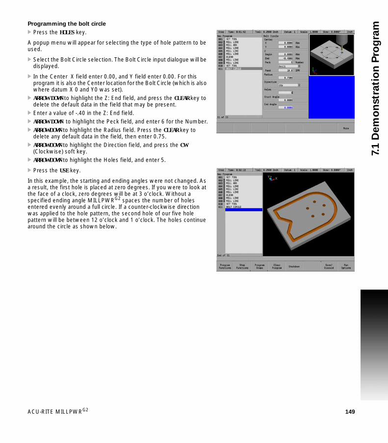
ACU-RITE MILLPWRG2 149
7.1
De
mo
nstr
ati
on
Pro
gra
mProgramming the bolt circle
Press the HOLES key.
A popup menu will appear for selecting the type of hole pattern to be used.
Select the Bolt Circle selection. The Bolt Circle input dialogue will be displayed.
In the Center X field enter 0.00, and Y field enter 0.00. For this program it is also the Center location for the Bolt Circle (which is also where datum X 0 and Y0 was set).
ARROW DOWN to highlight the Z: End field, and press the CLEAR key to delete the default data in the field that may be present.
Enter a value of -.40 in the Z: End field. ARROW DOWN to highlight the Peck field, and enter 6 for the Number. ARROW DOWN to highlight the Radius field. Press the CLEAR key to
delete any default data in the field, then enter 0.75. ARROW DOWN to highlight the Direction field, and press the CW
(Clockwise) soft key. ARROW DOWN to highlight the Holes field, and enter 5.
Press the USE key.
In this example, the starting and ending angles were not changed. As a result, the first hole is placed at zero degrees. If you were to look at the face of a clock, zero degrees will be at 3 o’clock. Without a specified ending angle MILLPWRG2 spaces the number of holes entered evenly around a full circle. If a counter-clockwise direction was applied to the hole pattern, the second hole of our five hole pattern will be between 12 o’clock and 1 o’clock. The holes continue around the circle as shown below.

150 7 Demonstration Program
7.1
De
mo
nstr
ati
on
Pro
gra
mTool change for the rectangular pocket
Begin by changing the tool.
Press the TOOL key. In the Set Tool dialogue enter 0.125 in the Size: Diameter field. ARROW DOWN to highlight the Tool Type field. With the Tool Type field highlighted, press the Tool Types soft key
to open the Tool Type drop down menu. ARROW DOWN to highlight the Flat End Mill. Press the ENTER key to select the tool.
ARROW DOWN to highlight the Spindle field. Select Forward by pressing the Forward soft key
ARROW DOWN to highlight the RPM field and enter 1300 using the numeric keypad.
ARROW DOWN to highlight the Require Change field and press the Yes softkey.
Press the USE key.
A new tool has now been added to the program, and a tool change will be required when running the program.
The program, when running, will stop at this point, and request the tool change before continuing.
The rectangular pocket, which is the final feature, can now be programmed.

ACU-RITE MILLPWRG2 151
7.1
De
mo
nstr
ati
on
Pro
gra
mProgramming the rectangular pocket
Press the RECT key.
A popup menu will appear for selecting the type of rectangle to be milled.
Highlight Pocket and press the ENTER key. The Rectangle Pocket dialogue will be displayed. The cursor will default to the first field (X1).
In the 1st Corner: X1 field enter -2.0. In the 1st Corner: Y1 field enter -1.0.
ARROW DOWN to Size: X field and enter 0.5 ARROW DOWN to Size: Y field and enter 2.0.
The 2nd Corner fields will automatically fill in based on the data from the 1st Corner: fields, and the Size: fields.
The Z Begin field, and Z End field inserts the same information that was entered for the Bolt Circle dialogue information.
ARROW DOWN to highlight the Z Begin field and enter .100. ARROW DOWN to highlight the Z End field and enter -.25. ARROW DOWN to highlight the Z Pass field, and enter 4 for the Number. ARROW DOWN to the Corner Blend Radius: field, and enter 0.125. ARROW DOWN to highlight the Direction field, and select CW
(Clock Wise) by pressing the CW soft key.
Press the USE key.
The demonstration program is now complete.
Save the program, replacing the existing program.

152 7 Demonstration Program
7.1
De
mo
nstr
ati
on
Pro
gra
m Testing the program
Whenever a new program has been created, it should always be tested first.
Run Options
Two options are available: Dry Run will move the table and Quill but no material will be cut, and Single Step will run the program one step at a time, then pause until GO is pressed to proceed with the next step.
Press the Run Options soft key. Press the selected option to run the program.
Dry run with table movement
The complete program will be run, and the cutting of the part will be displayed graphically as the program steps are being performed.
The following steps will run the program graphically, and the table will move.
Press the Run Options soft key. Press the Dry Run soft key. Highlight step 001 of the program. Press the Exit soft key. Press the GO soft key (the table will move).
Before you press the GO key to begin the dry run, ensure that the tool will not touch the workpiece when the quill begins to move. To avoid tool interference, do one or more of the following:- Lower the knee- Remove the tool or workpiece- Reestablish datum away from the part

ACU-RITE MILLPWRG2 153
7.1
De
mo
nstr
ati
on
Pro
gra
mRunning the program
The first step in running a new program is to establish datum. Remember to chose the center of the bolt circle as datum.
Place the workpiece into a vise. Place the first tool of the program into the spindle. From the DRO screen, press the Move Table soft key. Using the
arrows, and soft keys, position the workpiece under the tool where the center of the bolt circle’s datum is to be.
After the table has been properly positioned, press the Exit soft key to return to the DRO screen.
Touch the tool to the top surface of your workpiece. Press the Datum soft key. Press the X = 0, Y = 0 and Z = 0 soft keys to establish the current
tool position as datum. Press the DOWN ARROW key. Set the Z retract position 1” above the workpiece.
Press the USE key.

154 7 Demonstration Program
7.1
De
mo
nstr
ati
on
Pro
gra
m Tool changes
Whenever you encounter a Set Tool step, MILLPWRG2 will display the DRO screen and let you know which tool to load. If no tool diameter was programmed in the Tool Step, a prompt will be displayed to provide one.
Use the Move Table soft key and ARROW keys to move the workpiece away from the tool.
Insert the required tool into the spindle. Using the Move Table soft key, position the surface of a known
depth on the workpiece under the tool. Press the Datum soft key. Position your tool so that it touches a known surface, then enter that
position into the Z axis.
Press the USE key.
Raise the tool and press the GO key to continue the program.
Clearing the program
Press the DRO/PGM key to return to the Program mode. Press the Clear Program soft key. Press the Yes soft key to confirm exiting the program.
The program is cleared from the screen, and at any time another program can be loaded or a new program written.
If a program is loaded, and saved, it does not have to be cleared to open a new program.
If for some reason a program can not be cleared with the Clear Program soft key, there is an alternate method.
Cycle the power to the console. While at the home (DRO mode) screen, prior to finding home, press and hold the CLEAR key for 5 seconds.
Follow the instructions to clear the current program.

Milling and Drilling

156 8 Milling and Drilling
8.1
Mil
lin
g a
nd
Dri
llin
g 8.1 Milling and Drilling
Overview
Most of the program steps described in this section can be performed as one-step milling functions from the DRO screen or be included as steps in a program. Many of the dialogues are similar in the way that the data is entered. Much of the information in this chapter should be familiar after performing the demonstration program in Chapter 7.
Set Tool defines the tool and should appear as the first step in a program. A Set Tool step is required anywhere a tool change is required. MILLPWRG2 will apply the latest tool setting to the program steps that follow. See "Selecting a tool" on page 139 as the following information is very similar.
For complete information regarding a 2 Axes system Refer to Chapter 1, "Operating in 2 Axes and 3 Axes Modes" on page 31.
Warning: Spindle speeds used in this manual are for example only. A spindle speed is totally dependant on many factors (i.e. material, if coolant is used, tool diameter, etc.). The speeds listed are not meant to be a recommendation.

ACU-RITE MILLPWRG2 157
8.1
Mil
lin
g a
nd
Dri
llin
gSelecting a tool
The first step for a program is to choose the tool that will be used to begin the machining. For this example, a 1/4” diameter Flat End Mill will be used as an example.
Press the DRO/PGM key to enter PGM mode. Press the Program Steps soft key. Press the Tool soft key to open the Set Tool dialogue.
In the Set Tool dialogue, the tool settings may be entered directly into the fields, the current settings from a tool in the Tool Table may be imported into the dialogue, or a tool in the table may be programmed by its number.
Entering the Tool data
In the Set Tool dialogue the cursor defaults to the Size: Diameter field. Enter 0.25 in the Size / Diameter field.
Select the unit of measure using the Inch or MM soft keys if a change is required.
ARROW DOWN to highlight the Tool Type field. The Length: field will be left blank.
Enter the plunge angle to be used when ramping into pockets. If the tool can safely plunge straight down into the material, press
the Plunge soft key or enter 90° for the angle. ARROW DOWN to highlight the Tool Type field, press the Tool Types soft
key to open the Tool Type drop down menu. ARROW DOWN to highlight the Flat End Mill. Press the ENTER key to select the tool.
Though in most cases, pressing the ENTER key will enter the data into the field, and place the cursor into the next field, the ARROW keys will be used in these steps for navigation, and entering data.
In most dialogues that contain a drop down menu, there are soft keys available for choosing a selection. These examples will refer to the use of the soft keys when available.

158 8 Milling and Drilling
8.1
Mil
lin
g a
nd
Dri
llin
g Importing Tool Settings from the Tool Table
Cursor to the Diameter field. Press the Tool Table soft key to open the table. Cursor to the tool to be used and press the USE key. The tool’s
diameter, length, plunge angle, and type are transfered to the Set Tool dialogue.
Specifying the tool by its tool table number
Cursor to the Tool Number field. If the tool’s number is known, enter the number (1-99), and press
the ENTER key. If the tool’s number is not known, press the Tool Table soft key to
open the table. Cursor to the tool to be used and press the USE key. The tool’s
number is transfered to the Set Tool dialogue.
Entering spindle data
ARROW DOWN to highlight the Spindle: field. Press the Forward soft key.
Entering speed data
ARROW DOWN to the Speed: field (RPM) and enter the speed required (e.g. 1300) using the numeric keypad.
When the tool is specified by number, only the tool number is saved to the program. The current tool settings for the specified tool are displayed in the dialogue, but not saved as part of the program step. The tool settings (diameter, length, plunge angle, and type) are retrieved from the tool table each time the SET TOOL step is run.

ACU-RITE MILLPWRG2 159
8.1
Mil
lin
g a
nd
Dri
llin
gTool position
The tool position is optional. The table and/or quill will move to the entered coordinates before prompting to change the tool.
Require change
The program will not normally prompt a tool change if the current tool matches the tool programmed in the step. Select YES to pause the program and prompt for the tool change.
Entering tool position
ARROW DOWN to tool position and enter the location where it is best to make a tool change away from the part and fixtures.
ARROW DOWN to the Required Change field and select Yes, or No.
Press the USE key.
The programming of a part can now begin.
If the tool is programmed by number, the system will pause and prompt to change the tool regardless of the require change setting.
The current and programmed tools match if the diameter, length, plunge/ramp angle, and type are the same. The diameters and lengths match if the physical sizes are the same, whether the tool is programmed in INCH or MM.
The program will pause for changing spindle speed or direction whether or not a tool change is necessary.
MILLPWRG2 moves to the Tool Position before prompting the user for a tool change, making it unnecessary to program a Position Drill step before a tool change.
MILLPWRG2 prompts the user to change the tool if the Set Tool step has a different tool than the one currently mounted (as indicated in the status bar). If the Require Change field is set to Yes, then MILLPWRG2 will always pause and prompt the user for a tool change (even if the Set Tool matches the currently mounted tool).
Tool length offsets are discussed on the following pages.
If the Tool Table is used to enter a tool, MILLPWRG2 will fill in the Diameter and Length fields in PGM mode only.

160 8 Milling and Drilling
8.1
Mil
lin
g a
nd
Dri
llin
g Repeatable tool length offsets
Programming a tool
When a program is using the Tool Length function, there are two requirements that must be followed to ensure that the tip of all additional tools is actually where MILLPWRG2 has calculated it to be.
All tools used must have a fixed, repeatable length. The surface that the tool touches off on must be a repeatable
surface and used for all tools added to the program.
This also applies to all tools added to the Tool Table.
Setting the Datum using an electronic edge finder is for illustration only, and is not a requirement.
Press the Datum soft key. Touch the first tool to the top surface that will be used to set all other
tools. Press the Z = 0 soft key.
The Z axis Datum is now set to 0.00.
All tools entered into the tool table will have length offsets relative to the first tool Datum. All tools entered after the first tool, whether into the tool table or into a program should have their length set using the Teach Tool Length soft key.
Once you have identified the tools you will be using, you can program the Tool Length Offsets into the Set Tool steps.
When all tools have been added to a program with their tool length offset programmed, MILLPWRG2 will retain the offset information between each tool and the Datum.
If a program that is using tool offsets requires a change from where the initial first tool datum was set, MILLPWRG2 will reset the offset information for the remaining tools.
When setting a the Datum, consideration of the height of the new location can avoid possible tool collision with the part when running the program. If necessary, reset the Z Retract height.
Tools and their offsets can be used from the Tool Table, and inserted into a program. The Datum for the program can be set at a new location as mentioned above. MILLPWRG2 will reset the offset information for the remaining tools to the new location. Their offset will stay relevant to the new Datum.
After the tool information is established in the program, later you can edit the values as needed to adjust for accuracy and wear.

ACU-RITE MILLPWRG2 161
8.1
Mil
lin
g a
nd
Dri
llin
gChanging to a tool of unknown length in DRO mode
If you are in the DRO mode and need to set a new tool, do the following:
Place the tool in the spindle. From the DRO mode, press the TOOL key. Enter the tool diameter, delete any data in the Length field. Enter the necessary data in the remaining fields where applicable. Press the GO key.
An Operator intervention message will appear asking you to “use” the selected tool.
Press the GO key to confirm that you have installed the tool.
At this point, your program’s tool length offsets are not valid. Follow the steps below to reestablish the Z axis datum and tool length offsets for your program.
Position the tool over the surface where the Datum was established for the other tools.
Touch the tip of the tool to the top surface. Press the Teach Tool Length soft key.
MILLPWRG2 will now add this tool to the known tool offsets, and the program’s tool length offsets are now valid.
This tool length offset is only valid while the tool is mounted. Once this tool is removed, these steps must be repeated to re-establish the tool length when it is used again.

162 8 Milling and Drilling
8.1
Mil
lin
g a
nd
Dri
llin
g Changing to a tool of unknown length in a program
When running a program, it is possible to switch between tools of known length, to using a tool that has a non-repeatable length.
When the tool which has a non-repeatable length is mounted, it’s length will be established in the same manner as above in DRO mode.
Place the tool in the spindle. In the Set Tool dialogue, enter the necessary data in the fields
where applicable, but delete any data in the Length field. Press the USE key.
At this point, your program’s tool length offsets are no longer valid. perform the following steps to reestablish the Z axis datum and tool length offsets for the program.
Position the tool over the surface where the Datum was established for the other tools.
Touch the tip of the tool to the top surface. Press the Teach Tool Length soft key.
MILLPWRG2 will now add this tool to the known tool offsets, and the program’s tool length offsets are now valid.
This tool length offset is only valid while the tool is mounted. Once this tool is removed, these steps must be repeated re-establish the tool length when it is used again.
By resetting Datum during a tool step within the program, all of the tool offsets in the program become valid again.

ACU-RITE MILLPWRG2 163
8.1
Mil
lin
g a
nd
Dri
llin
gPosition/Milling
MILLPWRG2 offers several Position / Milling functions that let you program a Line, Arc, Blend (Arc), Blend (Chamfer), and Contour that can be accessed directly using the Position/Milling soft key popup menu.
Position / Drill
The Position / Drill function will move the table to specific position based upon the X and Y axes coordinates entered.
Press the Position / Milling soft key. From the PGM screen, press the Pos key to access the Position / Drill dialogue.
Or press the Program Steps soft key, then press the Position / Milling soft key, and select Position / Drill from the popup menu.
In the Point field enter the X and Y axes coordinates. In the Z field enter the Begin and End depths. Enter either the number of pecks or the distance between each
peck (also know as Chip Break). If the option wanted is not displayed, go to Job Setup and select the other.
Select the job option to be used: Drill, Bore, or Position using the soft keys, or from the drop down menu.
Drill: Basic drilling cycle is generally used for center drilling or hole.
Bore: Generally used to make a pass in each direction on a bore or to tap with a self-reversing tapping head. It feeds from the begin depth to Z depth, and then feeds back to the retract height.
Position: Data can be entered to move the table to a position in the X & Y direction. Z moves are done manually.

164 8 Milling and Drilling
8.1
Mil
lin
g a
nd
Dri
llin
g Enter the Z axis feed rate. The default Feed IPM rate provided must be adjusted according to the current machining operation. This field will automatically use the last entered feed rate in the program
If you want the tool to retract enter either the number of retracts or the distance between each retract.
Enter the length of time (in seconds) the tool should dwell (pause) after it has retracted out of the part.
Enter the length of time (in seconds) the tool should dwell at the end depth before the final retract.
Press the USE key.
Line
Lines are defined by their “From” point (the point where they begin) and “To” point (the point where they end).
There are two ways you can program a line:With four coordinates (X1, Y1, X2, Y2).With three of the coordinates above (X1, X2, Y2 or X1, Y1, X2, etc.)
and an angle.
Choose a method based upon the information available from your print.
Entering data:
From the PGM screen, press the LINE key to access the Mill Line dialogue.
Or press the Program Steps soft key, then press the Position / Milling soft key, and select Line from the popup menu.
Enter the beginning X and/or Y axes coordinates into the From field. Enter the ending X and/or Y axes coordinates into the To field. Enter the Begin and End depths for the Z axis. Enter the Z axis feed rate. The default Feed ... IPM rate provided
must be adjusted according to the current machining operation. This field will automatically use the last entered feed rate in the program.
If one of the X- or Y-axes fields above was left blank, enter an angle. Highlight the Offset field and press the Left, Center, or Right soft
key. Enter the table’s feed rate. The default feed rate is what was
entered into Job Setup dialogue. Press the USE key.
If the tool size and type listed in the Tool field are incorrect, change the tool settings before running the program or one-step milling function.
If the tool size and type listed in the Tool field are incorrect, change the tool settings before running the program.

ACU-RITE MILLPWRG2 165
8.1
Mil
lin
g a
nd
Dri
llin
gArc
An arc can be defined several ways:
With a From point, To point and a radiusWith a From point, To point and a center pointWith a From, To and a 3rd point along the arcWith a start point to an end point for a sweep angle
Choose a method based upon the information available from part drawing. While programming, keep in mind that the arc's sweep angle is measured from the X axis.
Entering data:
From the PGM screen, press the ARC key to access the Arc dialogue. Or press the Program Steps soft key, then press the Position / Milling soft key, and select Arc from the popup menu.
Enter the beginning coordinates for the X axis (X1) and Y axis (Y1) in the From field.
Enter the ending coordinates for the X axis (X2) and Y axis (Y2) in the To field.
Enter the begin and end depths for the Z axis. Enter the Z axis feed rate. Enter the arc's radius, then press either the Major Arc or Minor Arc
soft key. (A Major Arc has a sweep angle greater than 180 degrees; a Minor Arc’s sweep angle is less than 180 degrees.)
Select the cutting direction. Press the CW soft key for a clockwise direction or the CCW soft key for a counter-clockwise direction.
ARROW DOWN and highlight the Offset field. Using the soft keys, select the tool offset— Left, Center, Right, Inside or Outside.
Enter the table’s Feed IPM.

166 8 Milling and Drilling
8.1
Mil
lin
g a
nd
Dri
llin
g If you need to enter a center coordinate, 3rd point and/or sweep angle press the More soft key:
Center field:
Enter the center coordinate’s position for the X and Y axes.
3rd Pointfield:
Enter your 3rd coordinate’s position for the X axis (X3) and Y axis (Y3).
Sweep Angle field:
Enter the sweep angle.
Information that appears in blue has been calculated. If any of these values are already displayed in blue, then MILLPWRG2 has enough data for the arc and has calculated the rest.
Press the USE key.
Note: If the tool size and type listed in the Tool field are incorrect, change the tool settings before running the program.
Blend/chamfer
A blend is an arc that connects two lines, two arcs or a line and an arc. The arc is tangent to the adjacent steps.
An inverted blend is also an arc that connects two lines, two arcs, or a line and arc. They are perpendicular to the adjacent steps.
The two steps to be blended can, but don't have to, intersect or touch. If they don't come into contact with each other, check that the radius is large enough to connect them.
It's also possible to close a contour (e.g., a triangle) using the blend feature by inserting a blend step immediately after the last step in the contour.
Enter the blend's radius, press the Close Contour soft key, and MILLPWRG2 will blend the last step with the first step.

ACU-RITE MILLPWRG2 167
8.1
Mil
lin
g a
nd
Dri
llin
gBlend
Highlight a step within your program where you want to place a blend.
From the PGM screen, press the BLEND key to access the Blend dialogue.
Or press the Program Steps soft key, then press the Position / Milling soft key, and select Blend (Arc) from the popup menu.
Select the blend type. A blend is tangent to the two steps. An inverted blend is perpendicular to the two steps.
Check that the steps listed in the From and To fields are the steps to be blended. If they're incorrect, press the CANCEL key and highlight the appropriate step.
Enter the blend's radius. Press the Close Contour soft key to blend the end of a contour with
the beginning. The step numbers in the To and From fields will automatically change.
Press the USE key.
The blend step can be added prior to adding the connecting line in the program step, or between two connecting lines. When placed before the connecting line is added, it will not be displayed until the connecting line is placed in the program.
Confirm that Blend is selected in the soft key.

168 8 Milling and Drilling
8.1
Mil
lin
g a
nd
Dri
llin
g Chamfer
A Chamfer is done in the same way, but with less steps. In the Size field enter the length of the chamfer.
A chamfer is a bevel or line that’s inserted between two lines to relieve sharp angles or corners on a part. A chamfer can be inserted between two intersecting lines whose steps are adjacent in the program step.
A chamfer can also close a contour (e.g., a triangle) by inserting the chamfer step immediately after the last step in the contour.
From the PGM screen, locate the lines where the chamfer is to be inserted between.
Highlight the second line. Press the BLEND key. Or press the Program Steps soft key, then press the Position / Milling soft key, and select Blend (Chamfer) from the popup menu.
Press the Chamfer soft key after the dialogue opens. Check that the steps listed in the From and To fields are the steps
to be blended. If they're incorrect, press the CANCEL key and highlight the appropriate step.
For Length 1, enter the distance from the common point to the From line.
For Length 2, enter the distance from the common point to the To line.
Press the Closed soft key to chamfer the end of a contour with the beginning
Press the USE key.

ACU-RITE MILLPWRG2 169
8.1
Mil
lin
g a
nd
Dri
llin
gContour
The Contour step enables you to approach and/or depart from your part on a straight line or with an arc.
The contour step must immediately follow the contour steps.Contours can only be associated with lines, arcs, blends and
chamfers. By adding contours before and/or after a continuous tool path, you'll avoid starts and stops striking against the workpiece edge.
With an arc approach/departure, the tool will take a rounded turn as it nears or exits the workpiece.
With a straight approach/departure, the tool path is extended away from the workpiece.
The step range can include one or more steps. If you're planning to add a contour to an individual step, the first and last steps in the range will be the same.
Because the approach and departure fields are independent of each other, you may select one or both for the step range you've chosen. Select None as the type for whichever option you don't want.
To program a contour:
From the PGM screen, highlight the step below the last step in the continuous contour.
Press the Program Steps soft key. Press the Position / Milling soft key. Select Contour from the popup menu. First and Last in the Step Range field will be filled in. If you wish to program an approach, select the Straight or Arc soft
key, or use the drop down menu as your approach type. Otherwise, press the None soft key.
Enter how far from the part you want the approach to begin in the Distance field.
To program a departure, select the Straight or Arc soft key, or use the drop down menu as your approach type. Otherwise, press the None soft key.
Enter how far from the part you want your tool to travel in the Distance field.
To program a Bottom finish cut, enter the amount of material to be removed during the bottom finish pass.
To program a Side finish cut, enter the amount of material to be removed during the side finish pass. A tool offset must be specified to initiate a side finish.
Enter the Feed Rate for the bottom and side finish passes. Enter a feed of 0 to skip the finish passes without removing the finish material.
Select either Forward or Reverse for the direction of the side finish pass. With Forward selected, the side finish pass is made in the same direction as previous passes. With Reverse selected, the side finish pass is made in the opposite direction.
Press the USE key.

170 8 Milling and Drilling
8.1
Mil
lin
g a
nd
Dri
llin
g Tool path description:
The tool path follows the profile of the contour steps. The Z step size is determined by the system and will not exceed the
specified distance or number of passes. The tool retracts to the active datum's retract position between Z
passes. Approach and departure moves are optional. For Line, the tool
approaches/departs with a linear move tangent to the first or last step of the contour.
For Arc, the tool approaches/departs with a tangential arc to a location away from the contour.
The bottom finish is the amount left on the Z axis to be removed with a separate bottom finish pass.The bottom finish pass is made in the direction of the original path.
The side finish is the amount left on the side to be removed with a separate side finish pass. The side finish pass is made in either the direction of the original path (forward) or in the opposite direction (reverse).
When finish feed is 0, the bottom and side finish passes will be skipped.
Rectangular and circular contours
Some steps can be defined as contours or to generate tool paths. When a step is a Contour it can be used as an island.
The Rectangle Pocket, Rectangle Slot, Circle Pocket, Radial Slot, and Circle Ring can be configured to be contours by setting the Type field to Contour.
The Type field can be viewed when the More soft key is active. If the Type field is not changed, then the step is a Pocket.
A step of type Contour only requires the fields that define its geometry to be entered. None of the machining related fields are needed.

ACU-RITE MILLPWRG2 171
8.1
Mil
lin
g a
nd
Dri
llin
gRectangular milling functions
MILLPWRG2 offers several rectangular milling functions that let you program pockets, frames, faces and slots. For 2 axes systems, Refer to Chapter 1, "Operating in 2 Axes and 3 Axes Modes" on page 31.
Rectangle pocket
A pocket is a cavity or area on the part where material is removed when you machine. You can program a rectangular pocket three ways:
Using the coordinates of two diagonal corners.Using the coordinates of one corner and the size of the pocket. The
X and Y size can be positive or negative dimensions which allows the 1st corner to be any of the corners of the pocket.
Using the coordinates of the center and the size of the pocket.
From the PGM screen, press the RECT key to access the Rectangle popup Menu.
Select Pocket from the popup menu.
Entering data
Enter the 1st Corner X1 and Y1 axes coordinates.
Now enter either the Size of the pocket or the 2nd Corner coordinates.
Either data entry will automatically fill in the fields for the other option.
To enter the Size, enter the length of the pocket along the X and Y axes.
Or enter the X and Y axes coordinates for the 2nd Corner. The 2nd corner must be located diagonally from the 1st corner.
Enter the Begin and End depths for Z. Enter either the number of passes or the distance between each
pass. Pass refers to the cuts that are used to machine the pocket to its End depth. Which choice is shown in the dialogue was selected in Job Setup.
Enter the Z axis Feed Rate. Add a corner blend radius or a chamfer to the corners of the
rectangular pocket. For Direction, press either the CW soft key for a clockwise cutting
direction or the CCW soft key for a counter-clockwise cutting direction.
ARROW DOWN or press the More soft key and enter the table’s feed rate. If programming by center and size, enter the Center X and Y axes
coordinates. You can tilt a rectangular pocket by identifying a tilt angle. Highlight
the Angle field and enter an angle measured from the X axis.

172 8 Milling and Drilling
8.1
Mil
lin
g a
nd
Dri
llin
g Finish
Finish allows you to leave some excess material that will be removed during the finish passes reducing tool marks. The sidefinish cut will automatically arc on and arc off.
Enter the amount of material on the bottom of the pocket to be removed during the bottom finish pass in the Bottom Finish field. If the Bottom Finish is left blank on a legacy program, it will use the same amount specified in the Side Finish field. Enter 0 if no material is to be left after roughing.
Enter the amount of material on the sides of the pocket to be removed during the side finish pass in the Side Finish field. Enter 0 if no material is to be left after roughing.
Enter the Feed Rate for the finish passes. Select the Direction for the finish cut. Press the CW soft key for a clockwise direction or the CCW soft key for a counter-clockwise direction.
Enter a stepover amount (how much you want your tool to cut on each pass).
The Type field is typically Pocket. Change to Contour to use only the geometry.
Press the USE key.
If the tool size and type listed in the Tool field are incorrect, change the tool settings before running your program.
Tool path description:
Machining of the rectangle pocket begins at its center. The tool ramps or plunges at the Z feed rate. The pocket is milled from the center out. The XY step size is determined by the system and will not exceed
the specified distance or percentage of the tool diameter. The pocket is machined at the feed rate programmed in the
rectangle pocket step. When the tool makes a cut greater than the step over such as the initial cut down the center of the pocket, the full cut override is applied to the feed. The full cut override only applies to the rough pass. The finish passes run entirely at the programmed finish feed.
The Z step size is determined by the system and will not exceed the specified distance or number of passes.
The tool retracts to Z Begin between Z passes. The finish allowances are optional. If specified, this amount is left
on the bottom and/or sides of the pocket to be removed on the finish passes.
When finish feed is 0, the finish passes will be skipped. Finish direction applies to both the bottom and side finishes.

ACU-RITE MILLPWRG2 173
8.1
Mil
lin
g a
nd
Dri
llin
gRectangle frame
When you program a rectangular frame, you define it by its first corner, and its size or diagonal corner. You can program a frame in one of three ways:
Using the coordinates of two diagonal corners.Using the coordinates of one corner and the size of the frame.Using the coordinates of the center and the size of the frame.
To program a rectangular frame:
From the PGM screen, press the RECT key to access the Rectangle popup Menu.
Select Frame from the popup Menu.
Entering data:
Enter the 1st Corner X1 and Y1 axes coordinates.
Now enter either the Size of the frame or the 2nd Corner coordinates.
Either data entry will automatically fill in the fields for the for the other option.
To enter the Size, enter the length of the frame along the X and Y axes.
Or enter the X and Y axes coordinates for the 2nd Corner. The 2nd corner must be located diagonally from the 1st corner.
Enter the Begin and End depths for Z. Enter either the number of passes or the distance between each
pass. Pass refers to the cuts that are used to machine the frame to its End depth. Which choice is shown in the dialogue was selected in Job Setup.
Enter the Z axis Feed Rate.
174 8 Milling and Drilling
8.1
Mil
lin
g a
nd
Dri
llin
g Add a corner blend radius or a chamfer to the corners of the rectangular frame.
For Direction, press either the CW soft key for a clockwise cutting direction or the CCW soft key for a counter-clockwise cutting direction.
ARROW DOWN or press the More soft key and select the Tool Offset. ARROW DOWN or press the More soft key and enter the table’s feed rate. Enter the Center X and Y axes coordinates. You can tilt a rectangular frame by identifying a tilt angle. Highlight
the Angle field and enter an angle measured from the X axis.
Finish:
Finish allows you to leave some excess material that will be removed during the finish cut reducing tool marks. The finish cut will automatically arc on and arc off.
Enter the amount of material to be removed during the finish cut in the Cut field.
Enter the Feed Rate for the finish cut. Select the finish cut’s Direction. Press the CW soft key for a
clockwise direction or the CCW soft key for a counter-clockwise direction.
Press the USE key.
If the tool size and type listed in the Tool field are incorrect, change the tool settings before running your program.
Tool path description:
Machining of the frame begins at the center of the line forming the top of the rectangle.
The tool plunges at the Z feed rate. The frame is milled in the direction programmed (CW or CCW) The Z step size is determined by the system and will not exceed the
specified distance or number of passes. The side finish allowance is optional and is only applicable to frames
with a tool offset. If specified, this amount is left on the side of the frame to be removed on the finish pass.
When finish feed is 0, the finish pass will be skipped.

ACU-RITE MILLPWRG2 175
8.1
Mil
lin
g a
nd
Dri
llin
gRectangle face
The “Rectangle Face” step provides a quick way to face off your workpiece. Simply enter the coordinates from one corner and either the size of the area to be faced off or the coordinates for a diagonal corner. MILLPWRG2 will position your table at the lower left end of the area you've programmed.
You can program a rectangle face in three ways:
Using the coordinates of two diagonal corners.Using the coordinates of one corner and the size of the face.Using the coordinates of the center and the size of the face.
To program a rectangular face:
From the PGM screen, press the Rectangle key to access the popup Menu.
Select Face from the popup Menu.
Entering data:
To program a rectangle face using the coordinates of two diagonal corners or by using the coordinates of one corner and the size of the face:
Enter the 1st Corner X1 and Y1 axes coordinates.
Now enter either the Size of the face or the 2nd Corner coordinates. Either data entry will automatically fill in the fields for the for the
other option.
To enter the Size, enter the length of the face along the X and Y axes.
Or enter the X and Y axes coordinates for the 2nd Corner. The 2nd corner must be located diagonally from the 1st corner.
Enter the Begin and End depths for Z. Enter either the number of passes or the distance between each
pass. Pass refers to the cuts that are used to machine the face to its End depth. Which choice is shown in the dialogue was selected in Job Setup.
Enter the Z axis Feed Rate.
To program a rectangle face using the coordinates of the center and the size of the face:
ARROW DOWN or press the More soft key. Enter the Center X and Y axes coordinates. Enter the Size of the face by entering the length of the face along
the X and Y axes. Enter the Begin and End depths for Z. Enter either the number of passes or the distance between each
pass. Pass refers to the cuts that are used to machine the face to its End depth. Which choice is shown in the dialogue was selected in Job Setup.
Enter the Z axis Feed Rate.

176 8 Milling and Drilling
8.1
Mil
lin
g a
nd
Dri
llin
g Other settings:
You can tilt the face by identifying a tilt angle. Highlight the Angle field and enter an angle measured from the X axis.
Enter a stepover percentage (how much the tool to is to overlap on each pass) for the Finish pass.
For Tool Path Priority, select either Shortest Path or Even Spacing.
With Shortest Path, the tool removes the same amount of material on every pass. To avoid leaving an edge, the tool machines along the center of the material on the last pass.
With Even Spacing, the tool steps by an even amount in the XY plane from the first pass to the last.
Depending on the width of the face and the stepover size, Even Spacing may require additional passes compared to Shortest Path, but the surface finish may have a more even apprearance.
Tool path description:
Machining of the face begins near the first corner.
The tool plunges at the Z feed rate. The tool makes back and forth passes in the XY plane along the
defined length of the face. Tool motion extends beyond the ends of the rectangle by an amount equal to the tool radius.
The XY step size is determined by the system and will not exceed the specified percentage of the tool diameter.
If Shortest Path is selected, the tool centers itself on the final XY pass.
If Even Spacing is selected, the tool has the same stepover on the final pass as on the first pass.
The Z step size is determined by the system and will not exceed the specified distance or number of passes.
The tool retracts to the active datum's retract position between Z passes.

ACU-RITE MILLPWRG2 177
8.1
Mil
lin
g a
nd
Dri
llin
gRectangle slot
You can program a slot two ways:
By entering the center point of each arc and the slot's widthBy entering the center point of one arc, the length and width of the
slot, and an angle.Using the coordinates of the center and the length of the slot.By entering the center point of the slot and the slot's width and
length.
Choose a method based upon the information available from your print.
To program a slot:
From the PGM screen, press the RECT key to access the Rectangle popup Menu.
Select Slot from the popup Menu.
Entering data:
Enter the 1st Arc Center X1 and Y1 axes coordinates.
Now enter the size of the pocket in the 2nd Arc Center fields X2 and Y2 axes coordinates.
Enter the Begin and End depths for Z. If this information was entered on a previous program step, it will automatically be displayed. If necessary, adjust the data for this program step.
Enter either the number of passes or the distance between each pass. Pass refers to the cuts that are used to machine the slot to its End depth. Which choice is shown in the dialogue was selected in Job Setup.
Enter the Z axis Feed Rate. For Direction, press either the CW soft key for a clockwise cutting
direction or the CCW soft key for a counter-clockwise cutting direction.
Enter the Slot Width. The slot length will automatically be calculated.
ARROW DOWN or press the More soft key and enter the table’s feed rate. Enter the Center X and Y axes coordinates.

178 8 Milling and Drilling
8.1
Mil
lin
g a
nd
Dri
llin
g The Tool fields will automatically be filled in with the current tool loaded. If a different tool is to be used, enter a Set Tool step prior to this program step.
You can tilt a rectangular slot by identifying a tilt angle. Highlight the Angle field and enter an angle measured from the X axis.
The Finish fields will assume the same as the previous finish fields in the program if it exists. Otherwise this data must be added if necessary to include it.
For Direction, press either the CW soft key for a clockwise cutting direction or the CCW soft key for a counter-clockwise cutting direction.
Enter a stepover percentage (how much the tool to is to overlap on each pass).
The Type field is typically Pocket. Change to Contour to use only the geometry.
Press the USE key.
Tool path description:
Machining of the slot begins at its first arc center location. The tool ramps or plunges at the Z feed rate. The slot is milled from the center out. The XY step size is determined by the system and will not exceed
the specified distance or percentage of the tool diameter. The slot is machined at the feed rate programmed in the step.
When the tool makes a cut greater than the step over such as the initial cut down the center of the slot, the full cut override is applied to the feed. The full cut override only applies to the rough pass. The finish passes run entirely at the programmed finish feed.
The Z step size is determined by the system and will not exceed the specified distance or number of passes.
The tool retracts to Z Begin between Z passes. The finish allowances are optional. If specified, this amount is left
on the bottom and/or sides of the pocket to be removed on the finish passes.
When finish feed is 0, the finish passes will be skipped. Finish direction applies to both the bottom and side finishes.

ACU-RITE MILLPWRG2 179
8.1
Mil
lin
g a
nd
Dri
llin
gCircular milling functions
MILLPWRG2 offers several circular milling functions that let you program pockets, frames, ring, and helix. Refer to Chapter 1, "Operating in 2 Axes and 3 Axes Modes" on page 31 for information regarding 2 Axes Systems.
Circle pocket
A pocket is a cavity or area on your part where material is removed when you machine. You can program a circular pocket by indicating the center point and radius.
To program a circular pocket:
From the PGM screen, press the CIRCLE key to access the Circle popup Menu.
Select Pocket from the popup Menu.
Entering data:
Enter the X and Y axes coordinates for the center of the pocket.
Enter the Begin and End depths for Z. Enter either the number of passes or the distance between each
pass. Pass refers to the cuts that are used to machine the pocket to its End depth. Which choice is shown in the dialogue was selected in Job Setup.
Enter the radius. For Direction, press either the CW soft key for a clockwise cutting
direction or the CCW soft key for a counter-clockwise cutting direction.
The Tool fields will automatically be filled in with the current tool loaded.
Enter the Z axis Feed Rate. The last feed rate used previously in the program will be displayed.

180 8 Milling and Drilling
8.1
Mil
lin
g a
nd
Dri
llin
g ARROW DOWN or press the More soft key. The Finish fields will assume the same as the previous finish fields
in the program if it exists. Otherwise this data must be added if required.
For Direction, press either the CW soft key for a clockwise cutting direction or the CCW soft key for a counter-clockwise cutting direction.
Enter a stepover percentage (how much the tool to is to overlap on each pass). The last stepover percentage used previously in the program will be displayed
The Type field is typically Pocket. Change to Contour to use only the geometry.
Press the USE key.
If the tool size and type listed in the Tool field are incorrect, change the tool settings before running your program.
Tool path description:
Machining of the pocket begins at the center and works outward. The tool ramps or plunges at the Z feed rate. The XY step size is determined by the system and will not exceed
the specified distance or percentage of the tool diameter. The Z step size is determined by the system and will not exceed the
specified distance or number of passes. The tool retracts to Z Begin between Z passes. The finish allowances are optional. If specified, this amount is left
on the bottom and/or sides of the pocket to be removed on the finish passes.
When finish feed is 0, the finish passes will be skipped. Finish direction applies to both the bottom and side finishes.

ACU-RITE MILLPWRG2 181
8.1
Mil
lin
g a
nd
Dri
llin
gCircle frame
A frame is a cavity or area on your part where material is removed when you machine. You can program a circular frame by indicating the center point and radius.
To program a circle frame:
From the PGM screen, press the CIRCLE key to access the Circle popup Menu.
Select Frame from the popup Menu.
Entering data:
Enter the X and Y axes coordinates for the center of the frame.
Enter the Begin and End depths for Z. Enter either the number of passes or the distance between each
pass. Pass refers to the cuts that are used to machine the frame to its End depth. Which choice is shown in the dialogue was selected in Job Setup.
Enter the Z axis Feed Rate. The last feed rate used previously in the program will be displayed.
Enter the radius. For Direction, press either the CW soft key for a clockwise cutting
direction or the CCW soft key for a counter-clockwise cutting direction.
The Tool fields will automatically be filled in with the current tool loaded.
Select the Offset from the drop down menu, or the soft keys Left, Center, Right, Inside, Outside.
Enter the Z axis Feed Rate. The last feed rate used previously in the program will be displayed.

182 8 Milling and Drilling
8.1
Mil
lin
g a
nd
Dri
llin
g ARROW DOWN or press the More soft key. The Finish and Feed fields will assume the same as the previous
finish fields in the program if it exists. Otherwise this data must be added if required.
For Direction, press either the CW soft key for a clockwise cutting direction or the CCW soft key for a counter-clockwise cutting direction.
Press the USE key.
If the tool size and type listed in the Tool field are incorrect, change the tool settings before running your program.
Tool path description:
Machining of the frame begins at the top of the circle.
The tool plunges at the Z feed rate. The frame is milled in the directions programmed (CW or CCW) The Z step size is determined by the system and will not exceed the
specified distance or number of passes. The side finish allowance is optional and is only applicable to frames
with a tool offset. If specified, this amount is left on the side of the frame to be removed on the finish pass.
When finish feed is 0, the finish pass will be skipped.

ACU-RITE MILLPWRG2 183
8.1
Mil
lin
g a
nd
Dri
llin
gCircle ring
A ring is a circular pocket with a circular island in the center. A ring is determined by its center point, outside radius (radius of the pocket) and inside radius (radius of the island).
The direction of the cut on the inside radius will determine whether you are climb cutting or conventional cutting. MILLPWRG2 will reverse the tool direction on the outside radius so that the cutting direction stays the same.
From the PGM screen, press the CIRCLE key to access the Circle popup Menu.
Select Ring from the popup Menu.
Entering data
Enter the X and Y axes coordinates for the center of the ring using the ARROW DOWN key to enter the data, and move to the next field.
Enter the Begin and End depths for Z. Enter either the number of passes or the distance between each
pass. Pass refers to the cuts that are used to machine the pocket to its End depth. Which choice is shown in the dialogue was selected in Job Setup.
Enter the Z axis Feed rate. The last feed rate used previously in the program will be displayed.
In the Radius field enter the Outside radius, then enter the Inside radius.
For Direction, press either the CW soft key for a clockwise cutting direction or the CCW soft key for a counter-clockwise cutting direction.
The Tool fields will automatically be filled in with the current tool loaded.
Enter the Z axis Feed rate. The last Feed rate used previously in the program will be displayed.

184 8 Milling and Drilling
8.1
Mil
lin
g a
nd
Dri
llin
g ARROW DOWN or press the More soft key. The Finish and Feed fields will assume the same as the previous
finish fields in the program if it exists. Otherwise this data must be added if required.
For Direction, press either the CW soft key for a clockwise cutting direction or the CCW soft key for a counter-clockwise cutting direction.
The Type field is typically Pocket. Change to Contour to use only the geometry.
Press the USE key.
If the tool size and type listed in the Tool field are incorrect, change the tool settings before running your program.
Tool path description:
Machining of the ring begins near the inner radius and works outward.
The tool ramps or plunges at the Z feed rate. The XY step size is determined by the system and will not exceed
the specified distance or percentage of the tool diameter. The ring is machined at the feed rate programmed in the step.
When the tool makes a cut greater than the step over such as the initial cut around the ring, the full cut override is applied to the feed. The full cut override only applies to the rough pass. The finish passes run entirely at the programmed finish feed.
The Z step size is determined by the system and will not exceed the specified distance or number of passes.
The tool retracts to the active datum's retract position between Z passes.
The finish allowances are optional. If specified, this amount is left on the bottom and/or sides of the pocket to be removed on the finish passes.
When finish feed is 0, the finish passes will be skipped. Finish direction applies to both the bottom and side finishes. To
match cutting convention the outer radius is machined in the opposite direction of the inner radius.

ACU-RITE MILLPWRG2 185
8.1
Mil
lin
g a
nd
Dri
llin
gCircle helix
The circle helix can only be performed with a 3 axes system.
A helix is defined by one of two ways:
By the radius, depth and pitchBy the radius, depth and number of revolutions
To program a helix:
From the PGM screen, press the CIRCLE key to access the Circle popup Menu.
Select Helix from the popup Menu.
Entering data
In the Center field enter the X and Y axes coordinates for the center of the helix using the ARROW DOWN key to enter the data, and move to the next field.
Enter the Begin and End depths for Z. In the Radius field enter the radius. For Direction, press either the CW soft key for a clockwise cutting
direction or the CCW soft key for a counter-clockwise cutting direction.
In the Revolutions fields, enter either the pitch (number of revolutions per Z travel) or the total number of revolutions. The other field will automatically be filled in.
The Tool field will default to the current tool selected. In the Offset field select Inside for a external helix, or Outside for an
internal helix. Enter the Z axis Feed Rate. The last feed rate used previously in the
program will be displayed. Start Angle (optional). Enter the angle where the helix begins
(3 o’clock position is 0 degrees; 12 o’clock position is 90 degrees). Press the USE key.
If the tool size and type listed in the Tool field are incorrect, change the tool settings before running your program.

186 8 Milling and Drilling
8.1
Mil
lin
g a
nd
Dri
llin
g Radial slot
A radial slot can be defined in multiple ways:
By the center, radius, start angle, and sweep angle.By the center, center point of first end arc, and sweep angle.By the center and center point of both end arcs.By the radius and center point of both end arcs.
Choose a method based upon the information available from your print.
To program a radial slot:
From the PGM screen, press the CIRCLE key to access the Circle popup Menu.
Select Slot from the popup Menu.
Entering data
If known, enter the coordinates of the 1st Arc Center. If known, enter the coordinates of the 2nd Arc Center. Enter the Begin and End depths for Z. Enter either the number of passes or the distance between each
pass. Enter the Z axis Feed Rate. The last feed rate used previously in the
program will be displayed. In the Radius field enter the radius. For Direction, press either the CW softkey for a clockwise cutting
direction or the CCW soft key for a counter-clockwise cutting direction.
Enter the Width of the slot. Enter the Start Angle to the slot's first Arc Center. Enter the Sweep Angle from the first Arc Center to the second Arc
Center. ARROW DOWN or press the More soft key. The Tool field will default to the current tool selected. In the Center field, enter the X and Y axes coordinates for the center
of the slot radius. The Finish and Feed fields will assume the same as the previous
finish fields in the program if it exists. Otherwise this data must be added if required.
The Type field is typically Pocket. Change to Contour to use only the geometry.
Press the USE key.
Tool path description:
Machining of the slot begins at its first arc center location. The tool ramps or plunges at the Z feed rate. The slot is milled from the center out.

ACU-RITE MILLPWRG2 187
8.1
Mil
lin
g a
nd
Dri
llin
g The XY step size is determined by the system and will not exceed the specified distance or percentage of the tool diameter.
The slot is machined at the feed rate programmed in the step. When the tool makes a cut greater than the step over such as the initial cut down the center of the slot, the full cut override is applied to the feed. The full cut override only applies to the rough pass. The finish passes run entirely at the programmed finish feed.
The Z step size is determined by the system and will not exceed the specified distance or number of passes.
The tool retracts to the active datum's retract position between Z passes.
The finish allowances are optional. If specified, this amount is left on the bottom and/or sides of the pocket to be removed on the finish passes.
When finish feed is 0, the finish passes will be skipped. Finish direction applies to both the bottom and side finishes.
Hole patterns
MILLPWRG2 includes several built-in routines that let you program hole patterns quickly and easily. The following hole patterns are described here:
Row of HolesRectangle FrameRectangle ArrayBolt Circle
Row of holes
A row of holes, can be programmed two ways:
By entering the coordinates of the first and last holeBy entering the coordinates of the first hole, the spacing between
each hole and the row’s angle.
The “From” point refers to the center of the first hole, while the “To” point is the center of the last hole. Any additional holes will be spaced equally between these two.
You’ll also be prompted for peck and tool retract values. “Peck” lets you break chips and reduce chip buildup during drilling operations. “Tool Retract” allows you to program MILLPWRG2 to raise the tool at regular intervals.
To program a row of holes:
MILLPWRG2 includes several built-in routines that let you program hole patterns quickly and easily
From the PGM screen, press the HOLES key to access the HOLES popup Menu.

188 8 Milling and Drilling
8.1
Mil
lin
g a
nd
Dri
llin
g Entering data:
Select the Row of Holes from the popup menu. In the From field, enter the X and Y axes coordinates for the center
of the first hole and ARROW DOWN to the next field. Now either: Enter the X and Y axes coordinates for the center of the
last hole in the To field; or perform the following step instead. ARROW DOWN and enter the distance between each hole (from center
point to center point) in the Hole Spacing field, then enter the angle of the row of holes.
ARROW DOWN, enter the Z fields, Begin, End, and Peck data. Select the type of machining to be done: Drill, Bore, or Position.
Either pick from the drop down menu, or the soft keys. Enter the Z axis Feed Rate. The last feed rate used previously in the
program will be displayed. Rapid is also available, select by using the Rapid soft key, or select from the drop down menu.
ARROW DOWN or press the More soft key. Additional information can be entered for tool retract and tool dwell. The tool field enters the current tool selected as reference
information. To use a different tool, that tool has to be entered as the current tool.
Press the USE key.

ACU-RITE MILLPWRG2 189
8.1
Mil
lin
g a
nd
Dri
llin
gHole frame and array
Hole Frame and Hole Array patterns require the same information, but their patterns differ slightly. Hole frames limit holes to the outside edge of a rectangular shape, while hole arrays allow holes along the outside edge and throughout the center.
Hole Frames and Hole Arrays can be defined three ways:
By the position of the 1st Corner, size, and the number of holes.By the position of the 1st Corner, position of the 2nd (diagonal)
Corner, and number of holes.By the position of the 1st Corner, size, and the number of holes.By the position of the center, hole spacing, and number of holes
Choose the method that’s easiest for you based upon the information from your print.
You’ll also be prompted for Peck and Tool Retract values. Peck lets you break chips and reduce chip buildup during drilling operations. Tool Retract allows you to program MILLPWRG2 to raise the tool at regular intervals.

190 8 Milling and Drilling
8.1
Mil
lin
g a
nd
Dri
llin
g Entering data:
From the PGM screen, press the HOLES key to access the HOLES popup Menu.
Select the Rectangle Array from the popup Menu.
Enter the 1st Corner X1 and Y1 axes coordinates.
Now enter either the Size of the array or the 2nd Corner coordinates. Either data entry will automatically fill in the fields for the for the
other option.
To enter the Size, enter the length of the array along the X and Y axes.
Or enter the X and Y axes coordinates for the 2nd Corner. The 2nd corner must be located diagonally from the 1st Corner. This information may be calculated automatically based on the option to put the data in the dialogue.
Enter the Begin and End depths for Z. Enter the Peck distance (depth).
Select the type of machining to be done: Drill, Bore, or Position. Either pick from the drop down menu, or the soft keys.
Enter the Z axis Feed rate. ARROW DOWN, and enter the number of holes in the X field, then the
number of holes in the Y field. ARROW DOWN or press the More soft key. Enter the center X and Y axes coordinates. The Hole Spacing field information may be calculated automatically
based on the option to put the data in the dialogue. If this is the data to be entered, enter the X and Y fields.
Enter the hole pattern angle in the Angle field, default is 0.00 (X axis).
The Tool Retract and Tool fields are optional. The Tool field enters the current tool selected as reference
information. To use a different tool, that tool has to be entered as the current tool.
Press the USE key.

ACU-RITE MILLPWRG2 191
8.1
Mil
lin
g a
nd
Dri
llin
gBolt circle patterns
A Bolthole Circle pattern is defined by its center point, radius and number of holes. You can program partial bolthole patterns by pressing the More soft key and entering a start angle and an end angle.
Entering data
From the PGM screen, press the HOLES key to access the HOLES popup Menu.
Select the Bolt Circle from the popup Menu.
Enter the Center X and Y axes coordinates.
Enter the Begin and End depths for Z. Also enter the Peck distance (depth).
Select the type of machining to be done: Drill, Bore, or Position. Either pick from the drop down menu, or the soft keys.
Enter the Z axis Feed rate. ARROW DOWN, and enter the required data in the Radius field. For Direction, press either the CW soft key for a clockwise cutting
direction or the CCW soft key for a counter-clockwise cutting direction.
In the Holes field enter the number of holes required in the bolt circle.
Enter the hole pattern angle in the Angle field, default is 0.00 (X axis).
In the start angle field enter the angle of the first hole in relationship to 0.00 (X axis).
ARROW DOWN or press the More soft key.
The Tool Retract and Tool Dwell fields are optional. The Tool field enters the current tool selected as reference
information. To use a different tool, that tool has to be entered as the current tool.
Press the USE key.

192 8 Milling and Drilling
8.2
Ad
dit
ion
al
Mil
lin
g F
un
cti
on
s 8.2 Additional Milling Functions
Step functions soft key
Additional functions are available from the PGM screen by pressing the Step Functions soft key.
Explode
When in PGM mode there are certain functions that can be exploded. Pressing the Explode soft key will explode a program step into several, more detailed steps. You can explode the following functions:
All HOLES functions, Row, Frame, Array and Bolt Circle Repeat, Mirror and Rotate Engrave Line and Engrave Arc
During the explode operation, the program list populates as it is being exploded. A message will be displayed “Exploding the selected step”.
A Cancel soft key becomes available during the explode operation. When this key is pressed, the explode operation stops, and the program returns to it original state. No other options are available during the explode operation.
Example:
A Bolt Circle with eight holes has been programmed.
Edit the program by first highlighting the Bolt Circle step. Press the Step Functions soft key Press the Explode soft key. MILLPWRG2 will explode the “Bolt Circle” step into eight steps (002
thru 009).
The step that was exploded is now replaced with the individual lines, arcs or positions that made up the step.
Highlight the step that represents the hole that will be edited and press the ENTER key, or press the CLEAR key to delete it.

ACU-RITE MILLPWRG2 193
8.2
Ad
dit
ion
al
Mil
lin
g F
un
cti
on
sReverse step
The reverse step feature instantly switches the From and To points and Tool Offset.
To reverse a milling function:
From the PGM screen, use the ARROW keys to highlight the step that you want to reverse.
Press the Step Functions soft key. Press the Reverse Step soft key.
Reverse path
With the reverse path option, you can reverse any continuous tool path. This will especially come in handy when you're working with DXF files. As you import DXF files, MILLPWRG2 will sort and then group the steps into a logical order, creating continuous paths. In some cases, the paths may need to be reversed after they've been imported so that your tool's offset, direction and beginning and end points satisfy your machining requirements.
As you become more familiar with this feature, you'll find other creative ways to use it to your advantage. For instance, you can save time as you're cutting a part by using a heavy cutting tool and a conventional cut for a rough first pass. On the second pass, switch to a finish cutter, then copy and reverse the path for a climb cut on the finish pass.
To reverse a continuous tool path:
From PGM mode, highlight any step within the continuous tool path that you want to reverse.
Press the Step Functions soft key. Press the Reverse Path soft key. The original steps are replaced
with steps in the reverse order.

194 8 Milling and Drilling
8.2
Ad
dit
ion
al
Mil
lin
g F
un
cti
on
s Change steps
The Change Steps feature gives you the ability to change or edit the depth, offset and feed rate of several steps simultaneously.
You can use this feature from anywhere within your program and does not require the specific step to be highlighted.
To Change Steps:
From the PGM screen, press the Step Functions soft key. Press the Change Steps soft key. Enter the first and last step numbers that you would like to change
in the Step Range field. Use the ARROW keys to select each field that you want to change and
enter the new data. Press the USE key.
Highlight the changed steps in the program sequence, then press the ENTER key. Each step should include the new settings.
Shift/Rotate steps
The purpose of the Shift/Rotate Steps feature is to transpose a range of steps from one location to another on the actual work piece.
This feature can be used from anywhere within the program, and does not require the specific step(s) to be highlighted.
To Shift Steps:
From the PGM screen, press the Step Functions soft key. Then press the Shift/Rotate Steps soft key. Then press the Shift soft key. Enter the first and last step numbers to be transposed. Enter in each axis field the distance to shift per axis. Leaving a field
empty will result in no shift per that axis. Press the USE key.
To Rotate Steps:
From the PGM screen, press the Step Functions soft key. Then press the Shift/Rotate Steps soft key. Then press the Rotate soft key. Enter the first and last step numbers to be transposed. Enter the X and Y axes coordinates for the center point of rotation.
Enter the angle of rotation. Press the USE key to apply the rotation to the selected steps.
Highlight the changed steps in the program sequence, then press the ENTER key. Each step should show the new axis coordinates.
ACU-RITE MILLPWRG2 195
8.2
Ad
dit
ion
al
Mil
lin
g F
un
cti
on
sDelete steps
MILLPWRG2 provides options for deleting steps in two ways: using the Delete Steps soft key or using the CLEAR key.
When deleting single steps, highlight the step, then press the CLEAR key.
When deleting a range of steps, the Delete Steps feature is usually the best option.
To delete a group of steps from a program:
From the PGM screen, press the Step Functions soft key. Press the Delete Steps soft key. In the Step Range field, enter the first and last step numbers to be
deleted. Press the USE key.
Copy/move steps
Copy/Move operations make it easy for you to duplicate or rearrange steps within your program. You'll find the Move feature especially useful for editing steps generated from a DXF file.
After you press the Copy/Move Steps soft key, you'll be asked to enter a step range, then either copy or move the steps and select a location where to copy or move the steps (i.e. Paste Location).
Press the Move soft key to relocate the steps. Press the Copy soft key to create an identical copy of the steps you've chosen (the original steps will remain in place). After you press the USE key, the new steps will be inserted into your program.
To copy or move steps:
From the PGM screen, highlight a step where you would like to add or insert the step(s) that you want to move or copy. If you are already in Copy/Move Steps then press Paste Location and scroll in the program where you want to move or copy the steps.
Press the Step Functions soft key. Press the Copy/move Steps soft key. Enter the first and last step numbers that you would like to move or
copy. Press either the Move Or Copy soft key. Make sure the desired
location is selected in the program or, use Paste Location to select where to move or copy the steps.
Press the USE key.

196 8 Milling and Drilling
8.2
Ad
dit
ion
al
Mil
lin
g F
un
cti
on
s Custom pockets
A custom pocket step must immediately follow a closed contour.
You can create a custom pocket from any closed contour. A closed contour is any shape consisting of lines, arcs, and/or blends (or chamfer), where the last step ends at the same point where the first step begins. MILLPWRG2 will indicate a closed contour with double lines to the right of the applicable steps in the program list.
The Custom Pocket step must be placed immediately following the last step of the closed contour. MILLPWRG2 will automatically fill in the step range for you. You’ll still need to fill in the "Staging Point" (optional) and set the feed rate for the custom pocket.
If a finish cut is specified, the system will mill the central portion of the pocket first, leaving the finish amount on the bottom and side. It will then mill the bottom pass followed by the side pass.
Custom pocket
Create a closed contour. Position the cursor immediately below the closed tool path contour. Press the Program Steps soft key. Press the Custom Pocket soft key and select Custom Pocket.
MILLPWRG2 will automatically fill in the step range for you. Enter the X and Y axes coordinates for the Staging Point. The tool
retracts and moves to the staging point before and after machining the pocket. Choose a staging point that helps avoid interference with fixturing. If moves to the staging point are not required, leave both X and Y fields blank.
Enter either the number of passes or the distance between each pass. Pass refers to the cuts that are used to machine the pocket to its End depth. What is shown on the dialogue is what was selected in JOB SETUP.
Enter the feed rate for the Z axis. Enter the table’s feed rate. In the Finish fields, enter the amount of material to be removed from
the bottom and sides during the finish passes. Enter the feed rate for the finish passes. For Direction, press either the CW soft key for clockwise or the CCW
soft key for a counter-clockwise direction. The direction is applied to both the bottom and side finishes.
Enter the stepover amount (how much you want your tool to cut on each pass).
Press the USE key.
The staging point is not the location at which the tool will enter the pocket material. Entry points are determined at run-time based on the pocket and tool geometry.

ACU-RITE MILLPWRG2 197
8.2
Ad
dit
ion
al
Mil
lin
g F
un
cti
on
s
Island
An island is a raised area (e.g. a boss) within a custom pocket that remains after material has been removed from around all of its sides.
Though islands are easy to program, they must be placed correctly within the program sequence. Steps for the island's continuous tool path must appear first, followed by the Island step. Steps for the custom pocket's continuous tool path must appear next, followed by the Custom Pocket step. You may program more than one island within the Custom Pocket.
To program an island:
Program a closed contour for the island. From the PGM screen, place the cursor below the last step of the
island’s closed contour. Press the Program Steps soft key. Press the Custom Pocket soft key. Select Island in the popup Menu. Check that the first and last steps listed in the step range match the
first and last steps for the island’s continuous tool path. If they’re correct, press the USE key; if they’re not, press the CANCEL key and check that the closed contour for the island is correct and/or the correct step has been highlighted.
Tool path description for custom pocket, island, and pilot drilling
Machining of the custom pocket begins at a location based on pocket geometry. The software automatically determines this location.
If a pilot drill operation is programmed, a prompt is displayed to use the pilot tool. Pilot holes are then drilled at each of the custom pocket's calculated entry locations. A prompt is then displayed to use the roughing tool.
The roughing tool ramps or plunges into the material at the Z feed rate. If pilot drill step was programmed then roughing tool will enter the material in the same locations where the pilot drilling was performed.
The CW/CCW direction of roughing passes is determined by the direction of the profile formed by the custom pocket.
The XY step size is determined by the system and will not exceed the specified distance or percentage of the tool diameter.
The system will determine the best location to start feeding into the part. Depending on the shape of the pocket and island contours, the pocket may be split into more than one region. The system will machine each region separately.

198 8 Milling and Drilling
8.2
Ad
dit
ion
al
Mil
lin
g F
un
cti
on
s The stepover must be 50% or less of the tool’s diameter. This is required to make sure that all material is removed.
The pocket is machined at the feed rate programmed in the custom pocket step. When the tool makes a cut greater than the step over, the full cut override is applied to the feed. Depending on the complexity of the pocket, the tool will change feed as needed. The full cut override only applies to the rough pass. Bottom and side finish passes run entirely at the programmed finish feed.
The Z step size is determined by the system and will not exceed the specified distance or number of passes. If not specified, the Z step size will not exceed the tool’s diameter.
The tool retracts to the active datum's retract position between Z passes.
The finish allowances are optional but recommended. If specified, this amount is left on the bottom and/or sides of the pocket and islands to be removed on the finish pass.
When the finish feed is 0, the finish passes will be skipped. Finish direction applies to both the bottom and side finishes.
A Custom Pocket will include all Islands that are within the custom pocket regardless of which step has been selected when the GO key is pressed.
If the Bottom Finish is left blank on a legacy program, it will use the same amount specified in the Side Finish field. If a separate bottom finish is not needed, enter 0 for the bottom finish amount. For additional control over rough, bottom, and side finish operations, use the advanced custom pocket cycles described in the next section.

ACU-RITE MILLPWRG2 199
8.2
Ad
dit
ion
al
Mil
lin
g F
un
cti
on
sAdvanced Custom Pocket Machining
Machining of custom pockets can be further enhanced using advanced custom pocket cycles. These optional steps apply specifically to the custom pocket and are programmed after the custom pocket/island path. In the program listing, they are shown as part of the custom pocket using dashed continuity lines.
The advanced cycles must be programmed in the following order – pilot drilling (optional), rough milling, bottom finish, and side finish.
After the last advanced cycle is completed, the Custom Pocket step is run to perform any remaining operations.
Pilot Drilling
If the tool programmed to machine the custom pocket is not able to feed directly into the material, a pilot tool step and pilot drill step should be programmed as part of the custom pocket. The system determines the location of each entry move into the material and drills pilot holes at those entry locations.
A Pilot Drill is programmed after the Custom Pocket step and before rough milling. If no rough milling steps are programmed after the Pilot Drill, the rough and finish operations are performed using the parameter settings in the custom pocket step.
To program a pilot drill operation:
From the PGM screen, place the cursor immediately below the custom pocket step.
Program a Set Tool step with the pilot drill tool's size and parameter settings.
Press the Program Steps soft key. Press the Custom Pocket soft key. Select Pilot Drill in the popup menu. Enter either the number of pecks or the distance between each
peck. Enter the Z axis feed rate. Press the USE key.
Always program a Set Tool step before a custom pocket step. This ensures that the system knows which tool to use.

200 8 Milling and Drilling
8.2
Ad
dit
ion
al
Mil
lin
g F
un
cti
on
s Rough Milling
It is possible to rough mill a custom pocket with multiple tools, starting with a larger tool to remove large amounts of material quickly followed by smaller tools to remove material inaccessible to the previous tool.
Each subsequent tool change and rough mill cycle only removes the material left by the previous coarse tool.
Rough milling is programmed after pilot drilling (optional) and before finishing operations. If no finish steps are programmed after the roughing steps, the finish operations are performed using the parameter settings in the custom pocket step.
To program a rough mill operation:
From the PGM screen, place the cursor immediately below the custom pocket or pilot drill step.
Program a Set Tool step with the rough drill tool's size and parameter settings.
Press the Program Steps soft key Press the Custom Pocket soft key Select Rough Mill in the popup menu. Enter the number of passes or distance between each rough pass
in the Z axis. Enter the Z axis feed rate. Enter the table's feed rate. Roughing passes with a coarse tool can specify a fine roughing
strategy. This specifies how the control should move the tool when the radius of the fine-roughing tool is larger than half the coarse roughing tool. Use Retract (default) to retract the tool and move to the starting point of the next area to be roughed. Use Contour to move the tool along the contour at the current depth between areas that need to be fine-roughed.
Press the USE key.
If no Rough Milling steps are programmed, the custom pocket uses the previously programmed tool for the rough pass. If one or more Rough Milling steps are programmed, the custom pocket cycle will not make an additional rough pass with the previously programmed tool.

ACU-RITE MILLPWRG2 201
8.2
Ad
dit
ion
al
Mil
lin
g F
un
cti
on
sBottom Finishing
The Bottom Finish removes the material from the bottom of the custom pocket. The amount of material to be machined by the bottom finish cycle is programmed in the Custom Pocket step.
The Bottom Finish step must be programmed after the rough milling cycle(s) and before side finishing. If no side finish step is programmed after the Bottom Finish step, the side finish operation is performed using the parameter settings in the custom pocket step.
To program a bottom finishing operation:
From the PGM screen, place the cursor immediately below the last rough mill step.
If necessary, program a Set Tool step with the finishing tool's size and parameter settings.
Press the Program Steps soft key. Press the Custom Pocket soft key. Select Bottom Finish in the popup menu. Enter the Z axis feed rate. Enter the table's finish feed rate. For Direction, press either the CW or CCW soft key. The direction is
applied specifically to the bottom finish operation. Press the USE key.
If no Bottom Finish step is programmed, the custom pocket uses the previously programmed tool for the bottom and side finish passes. If a Bottom Finish step is programmed, the custom pocket cycle will not make a separate bottom finish pass using the previous tool.
A bottom finish cycle must be programmed before any side finish cycles even if the programmed bottom finish amount is 0.

202 8 Milling and Drilling
8.2
Ad
dit
ion
al
Mil
lin
g F
un
cti
on
s Side Finishing
The Side finish step removes material from the side walls of the custom pocket and islands. It is possible to program multiple side finish steps by specifying decreasing amounts of material to be left by each subsequent side finish cycle. If necessary, tool steps may programmed between side finish cycles. The initial amount of material to be machined by the side finish cycle(s) is programmed in the Custom Pocket step.
Side Finish step(s) must be programmed after the Bottom Finish cycle.
To program a side finishing operation:
From the PGM screen, place the cursor immediately below the bottom finish step.
If necessary, program a Set Tool step with the finishing tool's size and parameter settings.
Press the Program Steps soft key. Press the Custom Pocket soft key. Select Side Finish in the popup menu. Enter the Z axis feed rate. Enter the amount of side material to remain after this operation.
Enter 0 to remove all of the remaining side material. Enter the table's finish feed rate For Direction, press either the CW or CCW soft key. The direction is
applied specifically to this side finish operation. Press the USE key.
If no Side Finish step is programmed, the custom pocket uses the previously programmed tool for a side finish pass. If one or more Side Finish steps are programmed, the custom pocket cycle will not make an additional side finish pass.
To ensure all of the finish material is removed, program the last Side Finish step with 0 in the finish field.
Warning: It is possible to start running a program from one of the cycles following the custom pocket. This should only be done if the previous cycles have already been run. Otherwise, the tool may rapid into material that the system assumes has been machined.

ACU-RITE MILLPWRG2 203
8.2
Ad
dit
ion
al
Mil
lin
g F
un
cti
on
sRepeat, rotate ...
The Repeat, Rotate, ... soft key provides milling functions available with the MILLPWRG2 product.
Repeat
Using this step you can repeat a section of the program with any combination of X, Y or Z offsets. The section may be repeated in a row (Linear) or one of two rectangular patterns (Array or Frame).
To program a repeat:
From the PGM screen, press the Program Steps soft key. Press the Repeat, Rotate, ... soft key. Select Repeat from the popup menu. Enter the number of the First step and the Last step in the Step
Range that you want to repeat. Select the pattern in which the steps are to be repeated. The default
is Linear. Enter the Offset for the X, Y and/or Z axis. The offset is the distance
between repeats. Enter the number of times you want to Repeat the original steps.
For Array and Frame patterns, enter the number of times the original steps are repeated along both the X and Y axes.
For Array and Frame patterns, enter the angle of the pattern’s grid. The default is 0 (X axis).
Press the USE key.
Rotate
With Rotate, you can rotate sections of programs.
The steps rotated must precede the Rotate step.
To program a rotate:
From the PGM screen, press the Program Steps soft key. Press the Repeat, Rotate, ... soft key. Enter the first and last steps in the Step Range that you would like
to rotate. Enter the X and Y axes coordinates for the Center point of rotation. Enter the Z offset. Enter the angle for each rotation in the Angle field. Enter the number of times required to rotate the original steps. Press the USE key.
The steps being repeated must precede the Repeat step. The number of repeats must be 1 or more.

204 8 Milling and Drilling
8.2
Ad
dit
ion
al
Mil
lin
g F
un
cti
on
s Footer note for Repeat and Rotate
When running a program at the point of executing a Repeat or Rotate, the footer in the program list view will display the line number, step type, and iteration of the step.
Mirror
The steps being mirrored must precede the Mirror step.With Mirror you can create a mirror image of an entire program or a
section of a program.
To program a mirror:
From the PGM screen, press the Program Steps soft key. Press the Mirror soft key. Enter the first and last steps in the Step Range that you would like
to mirror. Enter the X and Y axes coordinates which define the line across
which the step range is mirrored. Enter the Z offset. Press the USE key.
The mirrored steps maintain the same cutting convention as specified in the original steps.

ACU-RITE MILLPWRG2 205
8.2
Ad
dit
ion
al
Mil
lin
g F
un
cti
on
sOther steps
Other Steps soft key provides additional milling functions available with the MILLPWRG2 product.
From the PGM screen, press the Program Steps soft key, then press the Other Steps soft key to display the popup Menu.
With MILLPWRG2, you have the ability to engrave letters, numbers and symbols, along a straight line or on an arc. Choose from a simple, stick or stencil font. The character height, font and modifier settings you select will define your engraving’s appearance.
The tool diameter being used establishes the spacing between letters.
Engrave line
All ASCII characters within the decimal range of 32 - 126 are allowed, which includes Uppercase, Lowercase, Numbers, and Punctuation.
From the PGM screen, press the Program Steps soft key. Then press the Other Steps soft key. In the popup menu select Engrave Line. With the cursor in the Text input field, press the Alphanumeric Keyboard soft key, and insert the desired text. The text entered can be edited using the Up, Down, Left, Right and Backspace soft keys. To insert a new line, use the Insert Line soft key.
Enter the X and Y axes coordinates for the point at the lower left corner of the engraving.
Enter the character height. Enter the tilt angle if there is one. Enter the begin and end depths for the Z axis. Enter the Z axis feed rate. Select the font required from 3 choices, Simple, Stencil, or Stick,
soft keys, or the drop down menu. Select the Modifier as either the Normal or Mirrored soft key.
Normal is readable from left to right; Mirrored will make the engraving appear backwards.
Enter the table’s feed rate. Press the USE key.

206 8 Milling and Drilling
8.2
Ad
dit
ion
al
Mil
lin
g F
un
cti
on
s Engrave arc
All ASCII characters within the decimal range of 32 - 126 are allowed, which includes Uppercase, Lowercase, Numbers, and Punctuation.
From the PGM screen, press the Program Steps soft key. Then press the Other Steps soft key. In the popup menu select Engrave Arc. With the cursor in the Text input field, press the Alphanumeric Keyboard soft key, and insert the desired text. The text entered can be edited using the Up, Down, Left, Right and Backspace soft keys. To insert a new line, use the Insert Line soft key.
Enter the X and Y axes coordinates for the Text Center from the center of the engraving.
Enter the Character Height. Enter the Radius that the text will follow, and select Arc Up, or Arc Down (e.g. Arc Down is shown in the example).
Enter the begin and end depths for the Z axis. Enter the Z axis feed rate. Select the font required from 3 choices, Simple, Stencil, or Stick,
soft keys, or the drop down menu. Select the Modifier as either the Normal or Mirrored soft key.
Normal is readable from left to right; Mirrored will make the engraving appear backwards.
Press the USE key.

ACU-RITE MILLPWRG2 207
8.2
Ad
dit
ion
al
Mil
lin
g F
un
cti
on
sComment step
With MILLPWRG2, you have the ability to insert messages anywhere within a program. These messages can be displayed during machining (at run-time) or as Operator Intervention Messages (OIM). These messages become operational steps within the program and communicate pertinent information like "Rotate Part" or "Activate Coolant".
For comments that don't require an operator intervention, select No when asked if you want the comment displayed at run-time, and MILLPWRG2 will skip over them during machining. You can always retrieve the message by highlighting the comment step in your program steps list and pressing ENTER.
To program a comment step:
From the PGM screen, place the cursor below the last step where the comment is needed.
Press the Program Steps soft key. Press the Other Steps soft key. Select Comment in the popup Menu. Enter your message. You may include up to 60 characters, mixing
numbers, letters, spaces and symbols if needed. Press the Alphanumeric Keyboard soft key to chose alphabet characters. See "Keyboard" on page 39 for using the keyboard.
Highlight Display at Run Time. Press the Yes soft key to display the message during machining or the No soft key if you don't want the message displayed.
Press the USE key.
Auxiliary functions
In PGM mode, press the Program Steps soft key, then press the Other Steps soft key, and select Auxiliary Function from the popup menu.
In the Coolant field select Off, Mist, or Flood. Highlight the auxiliary relay(s) to be programed. The “Aux” numbers
in each field correspond to the relay output on the AMI. Select from the Off, On, and Pulsed soft keys for each. When Pulsed is selected, another field allows the duration of the pulse length to be entered in seconds. Enter the required time. The range is 0.1 to 999.9.

208 8 Milling and Drilling
8.2
Ad
dit
ion
al
Mil
lin
g F
un
cti
on
s
If PULSED is selected, then enter the amount of time (in seconds or tenths of seconds) for the relay to remain on. The maximum amount of time that a relay can pulse is 999.9 seconds.
Set the Display User Prompt for the step to pause before or after by pressing either the Before Step, or After Step. If a pause is not to be included, press the No softkey. These can also be selected from the drop down menu in the field window.
Set the Set Continuous field to Yes if the step is to be part of a continuous path. When set to Yes, the step does not break path continuity. The step will be run with the tool at the path depth. The Auxiliary Function step cannot be used to start or end a continuous path.
Press the USE key.
Position Description
ON The AMI output contacts will switch to an energized state.
OFF The AMI output contacts will switch to their default states.
PULSED The AMI output contacts will switch to an energized state for the length of time that is defined.
Display User Prompt
The AMI allows the operator to pause the step before or after the relays are turned on or off.
The pulse length must expire before the program continues to run.
The auxiliary function relays will not turn off automatically during an Operator Intervention Message (OIM).
The auxiliary function requires the AMI hardware for these settings to take affect automatically, otherwise they will activate operator prompts that must be responded to during the machining operation.

ACU-RITE MILLPWRG2 209
8.2
Ad
dit
ion
al
Mil
lin
g F
un
cti
on
sDwell
This is where the time is set for the machine to pause it’s movement, and stay in its current position for a programmed amount of time measured in seconds.
From PGM screen, press the Program Steps soft key, then press the Other Steps soft key.
Select Dwell in the popup Menu. Enter the Dwell time in seconds, tenth of seconds can also be
entered. Press the USE key.
Reference point
Reference points are commonly used to identify center points, tangent points and other part features. They can even be used as the basis for incremental moves.
As you program, note that placing a reference point in a continuous tool path will break the path. Otherwise, reference points do not affect your program's performance in any way in fact, MILLPWRG2 will skip over them altogether when you run a program.
To program a reference point:
From the PGM screen, press the Program Steps soft key, then press the Other Steps soft key.
Press the Reference Point in the popup Menu. Enter your reference point’s position for X, Y and Z. Press the USE key. The reference point will show graphically at the
programmed location.
A Dwell of 0 will cause the program to Pause until the operator presses GO.

210 8 Milling and Drilling
8.2
Ad
dit
ion
al
Mil
lin
g F
un
cti
on
s

Geometry/RPM
Calculator

212 9 Geometry/RPM Calculator
9.1
Ge
om
etr
y C
alc
ula
tor 9.1 Geometry Calculator
Overview
The MILLPWRG2 geometry calculator is used to construct Point/Line/Arc entities which can then be transferred to the part program.
MILLPWRG2 built-in calculator is capable of handling everything from simple arithmetic to complex trigonometry, geometry, and RPM calculations. The numeric keypad resembles a standard calculator with keys for numbers 0 through 9, four math function symbols (+, -, x, and ÷), a decimal point, and a positive/negative sign (+/-).
The geometry calculator is accessible from most screens and fields. Pressing the CALC key at any time will access the “stand-alone” calculator.
Accessing the geometry calculator
The geometry calculator is a stand-a-lone calculator that contains a listing of geometry steps and a graphic visualization.
The calculator is opened by pressing the CALC key and selecting the Geometry soft key. This is only available in PGM mode.
Press the CALC key to enter the calculator mode. Press the Geometry soft key.
To exit the calculator, press the CANCEL key at any time.

ACU-RITE MILLPWRG2 213
9.1
Ge
om
etr
y C
alc
ula
torGeometry calculator layout
The geometry calculator’s layout is similar to the part program in PGM mode. To differentiate it from the part program, the geometry step listing is on the right third of the screen and the graphic window is on the left two-thirds of the screen.
Geometry listing
The geometry calculator listing contains all steps:
Limited to geometry steps: point, line, and arc.
No continuity indicator. Margin is used to display step number for reference only, and has no incremental references. Use the ARROW keys for step selection.
To create a new Geo step, press the POINT, LINE, or ARC key. To edit an existing Geo step, cursor to the step and press ENTER or USE.
To delete an existing Geo step, cursor to the step and press CLEAR.Goto step number is supported.
Geometry graphic
The graphics window provides visual feedback:
Limited to 2D Line view.
Extents determined by the size of the entered steps and calculated results.
The block size matches the extents plus the normal margin. The datum symbol is displayed at (0,0). A ruler is also shown.
Highlight features: Focus feature – Blue Selected features – WhiteNew features – GreenNormal features – Yellow
A GeoPoint is displayed as a crosshair (×).

214 9 Geometry/RPM Calculator
9.2
Ge
om
etr
y U
se
r In
terf
ace 9.2 Geometry User Interface
Adding geometry features to listing
Geometry steps are limited to GeoPoints, GeoLines, and GeoArcs. A new step is added by pressing the POINT, LINE, or ARC key. As with a part program, the new step is added before the currently highlighted geo step
GeoPoint
Defined by single coordinate
GeoLine
Defined by combinations of From point, To point, and Angle.
GeoArc
Defined by combinations of From point, To point, Center point, 3rd point, Radius, Direction, and Sweep Angle. From and To points are optional (calculated at 12:00 position), otherwise, combinations follow programmed arcs.
Finding geometry solutions
Geo steps may also be created by finding points, lines, or arcs related to other Geo steps. These steps are created by selecting one or two steps and pressing the Find Point, Find Line, or Find Arc soft key.
To select or deselect a step:
Cursor to the step in the listing and press the Select Feature soft key to select it (soft key will display as being pressed).
To deselect a step, highlight the selected step, and press the Select Feature soft key again to release unselect the step.
No more than two features may be selected at a time. Selecting a third feature will deselect the oldest selection.

ACU-RITE MILLPWRG2 215
9.2
Ge
om
etr
y U
se
r In
terf
aceThe following table lists the features that are found based on the
selected features:
Items Find Point Find line Find Arc
1 Line End points of the given line Given a distance, lines parallel to the given line; lines perpendicular to the given line through its end points.
1 Arc Center point, end points. Given an angle, all lines tangent to and through the center point of the arc.
If angle is not specified, gives lines from the end points to the center point.
Complimentary arc.
2 Points Midpoint between the given points.
Line between the given points Given a radius, all arcs through the given points.
If radius is not specified, gives you two arcs, each tangent to both points with the midpoint as its center point.
1 Point1 Line
Point on the given line which, with the given point, would form a line perpendicular to the given line.
Line through the given point, one parallel and one perpendicular to the given line.
Given a radius, all arcs through the given point and tangent to a given line.
If radius is not specified, gives you two arcs, each tangent to the given line with the given point as its center point.
1 Point1 Arc
Points which, with the given point, would form lines tangent to the given arc and the shortest line from the given point to the given arc.
Lines through the given point tangent to the given arc, and the shortest line through the given point to the given arc.
Given a radius, all arcs through the given point and tangent to the given arc.
If radius is not specified, gives you all arcs tangent to the given arc with the given point as its center point.
2 Lines Intersection point of the given lines.
Line that bisects the angle formed where the given lines intersect; line perpendicular to the bisector.
Given a radius, all arcs tangent to both given lines
1 Line1 Arc
Point where given line intersects given arc.
Lines perpendicular to the given line and tangent to the given arc; shortest line to the given arc which is perpendicular to the given line.
Given a radius, all arcs tangent to the given line and the given arc.
2 Arcs Intersection points. Lines tangent to arcs; shortest line between arcs.
Given a radius, all arcs tangent to both arcs.

216 9 Geometry/RPM Calculator
9.2
Ge
om
etr
y U
se
r In
terf
ace Some operations require entry of additional information (distance,
angle, or radius). If needed, the user is prompted to enter a value by displaying a dialogue with fields that require additional data.
Managing geometry results
Since there are generally more solutions possible than desired, all possible solutions are presented (without a step number). To keep the result required, use the UP or DOWN ARROW keys to move the cursor to that feature and press the Keep One soft key.
When the cursor is on an existing feature the following soft keys are available:
When the cursor is on a feature that is not saved, the following soft keys are available:
After selecting the features to be retained, press the Clear Results soft key to remove the remaining unselected results from the listing.
Existing or new features can be viewed (or edited) by moving the cursor to the step and pressing the ENTER key.
The results are cleared automatically when the Find Function soft key is pressed again.
If the field is left blank, the data is calculated automatically.
Soft Key Function
Pressing the Keep All Results soft key will save all results found
Pressing the Clear Results soft key will clear all results not saved
Soft Key Function
Pressing the Keep One Result soft key will save the highlighted result found
Pressing the Clear Results soft key will clear all results not saved

ACU-RITE MILLPWRG2 217
9.2
Ge
om
etr
y U
se
r In
terf
aceReturning features to the part program
Press the Return Feature to transfer the current geo step to the part program. The soft key is disabled when it is not possible to transfer the current step to the program.
If no program step is open, Return Feature adds an equivalent program step at current location. The system returns to PGM view with the new step open.
If a program step is open, Return Feature (GeoPoint) returns the GeoPoint’s coordinate to the current field (x and y).
If a program step is open, Return Feature return of line or arc is only possible if feature matches the step type.
If the return type does not match the destination step/field, nothing is returned.
Geometry calculator functions
Pressing the Calc Function soft key opens a pop-up menu for selecting a function.
Clear calculator
Removes all Geo steps from the calculator.
Loading and saving calculator contents
Press Save Calculator to save the current GeoCalc session to internal memory.
Press Load Calculator to load the previously saved GeoCalc session into the calculator.
Loading the part program into the geometry calculator
The Load Program function adds the equivalent geometry steps (GeoPoint, GeoLine, and GeoArc) from the program to the calculator listing at the current cursor location.
Hole patterns are converted to a series of GeoPoints.Rectangle and circle steps are converted to profile GeoLines and
GeoArcsAll other steps (tool, replication, engrave, etc.) are not supported

218 9 Geometry/RPM Calculator
9.2
Ge
om
etr
y U
se
r In
terf
ace Program example
In some cases, a part drawing may not provide all of the dimensions needed to program the part. In the following illustration the coordinates of points B and C, where the arc is tangent to the sides, are unknown.
The coordinates will have to be identified before lines A-B and A-C and the arc that extends from point B to point C can be programmed.
Locating points B and C
First program an extended line from A to B, then program an extended line from A to C. Now use GeoCalc to calculate the rest.
Enter the extended line from A to B Enter the extended line from A to C at 45° Select lines A-B and A-C, and then use the Find Arc soft keyRecalculate point B, then return its coordinate and the arc into the
program
This example is explained fully in the following step by step illustrations.
Creating the program
Step 1
Point A is shown as the datum. Its absolute coordinates are 0, 0. In the part program. The first step will be to draw the line by entering the absolute coordinates for point A (0, 0) in the “From” field and point B (2, 0) in the “To” field.
Press the LINE key and enter the data in the GeoLine dialogue. Enter 0 in the From X1 field, and 0 in the From Y1 field.
Enter 2 in the To X2 field, and 0 in the Y2 field.
Press the USE key to enter the data into the program.

ACU-RITE MILLPWRG2 219
9.2
Ge
om
etr
y U
se
r In
terf
aceStep 2
The second step will be to draw a line by entering the absolute coordinates for point C (2, 2) in the “From” field and point A (0, 0) in the “To” field.
Press the LINE key and enter the data in the GeoLine dialogue. Enter 2 in the From X1 field, and 2 in the From Y1 field.
Enter 0 in the To X2 field, and 0 in the Y2 field.
Press the USE key to enter the data into the program.
The Geometry Calculator screen should now have these two lines displayed.

220 9 Geometry/RPM Calculator
9.2
Ge
om
etr
y U
se
r In
terf
ace Step 3
Finding the arc that’s tangent to the two lines.
Highlight 001 GeoLine and press the Select Feature soft key. The ARROW indicates that the feature has been selected.
Next, highlight 002 GeoLine and press the Select Feature soft key.
Press the Find Arc soft key. A pop up dialogue will display a field to define the arc radius.
Enter the radius of 1.
Press the USE key.
GeoCalc will display all the arcs that have a radius of 1 that are tangent with the two lines.
Using the ARROW keys, scroll through the list of found GeoArcs until the arc desired is highlighted.
Press the Keep One soft key, and GeoCalc will save the arc as item 003.
Then press the Clear Results soft key to erase the remaining arcs.

ACU-RITE MILLPWRG2 221
9.2
Ge
om
etr
y U
se
r In
terf
aceFinding the points of tangency
The points of tangency between the lines and the arc need to be determined. Now that the arc is in place, the coordinates of its end points are needed. Use GeoCalc’s find point feature to find the end points of the arc.
Highlight 001 GeoLine and press the Select Feature soft key. This will de-select the line and cause the arrow to disappear.
Highlight 002 GeoLine and de-select it.
Highlight 003 GeoArc and press the Select Feature soft key to select it.
Press the Find Point soft key. Three points will appear: one is the center of the arc and the others are the ends of the arc. The point on the bottom is the one needed; it’s point B on the drawing.
Using the ARROW key, scroll down through the list of GeoPoints until the point on the bottom is highlighted. Press the Keep One Result soft key.
Press the CANCEL key to return to the program.
Returning the line coordinate
Bring the GeoCalc results back into the program. When you press the Return Feature soft key, GeoCalc will transfer the feature you’ve identified into your part program.
Press the LINE key to begin a new Mill Line dialogue. Enter coordinates for the From point (point A). ARROW down to the X2 field. This is point B, one of the points found in GeoCalc.
Press the CALC key.
Press the Geometry soft key.
Highlight the GeoPoint representing point B (step 004). Press the Return Feature soft key. The program screen will return, and point B’s coordinates will appear in the To field.
Press the USE key to accept the line into the part program.
Program the tool step prior to proceeding.

222 9 Geometry/RPM Calculator
9.2
Ge
om
etr
y U
se
r In
terf
ace Returning the arc feature
Press the CALC key.
Press the Geometry soft key.
Highlight the GeoArc (step 003). Press the Return Feature soft key. The program screen will return and automatically add an arc step to your program and place the arc's information into the dialogue.
Press the USE key to accept the arc into the part program.
Finishing the program
Press the LINE key to begin a new Mill Line dialogue. Enter coordinates for the To point (point A).
Press the USE key to accept the line into the part program.

ACU-RITE MILLPWRG2 223
9.3
RP
M c
alc
ula
tor9.3 RPM calculator
RPM functions
MILLPWRG2 includes a built-in RPM calculator that allows you to make RPM calculations in seconds. It calculates the RPM based upon the tool diameter and surface speed.
If your cursor is in the RPM field of a “Set Tool” step before you open the RPM calculator, MILLPWRG2 can transfer the result directly into the field for you.
Using the RPM calculator
Press the CALC key.
Then press the RPM soft key.
RPM dialogue
Enter the diameter of the tool in the Diameter field. Soft keys are available to switch between Inch and MM.
Enter the surface speed for the material and cutter type in the Surface Speed field.
MILLPWRG2 will calculate the RPM.
Press the CANCEL key to return to the program.

224 9 Geometry/RPM Calculator
9.3
RP
M c
alc
ula
tor

Setup

226 10 Setup
10
.1 S
etu
p 10.1 Setup
Overview
The MILLPWRG2 has a set of parameters that can be setup as default values. Some of these values can be over-ridden per the program step dialogue, while others remain in affect until changed in the Job Setup dialogue.
Setup
Press the SETUP key to access the Job Setup dialogue. In the Job Setup dialogue the Installation Setup dialogue can be accessed by pressing the Install Setup soft key.
Job setup
Job setup parameters can be changed to accommodate specific machining requirements for each job.
Installation setup
Press the Install Setup soft key to access the Installation Setup dialogue.
Installation setup parameters are established during the initial installation and typically are not changed. The installation setup parameters are protected by a passcode. These parameters are described within the MILLPWRG2 Installation Manual.
Tool table
Press the Tool Table soft key to access the tool table.
The tool table is briefly discussed in this chapter. In the table, up to 99 tools can be entered and used in any program that would required that tool. See chapter 4.1 Tool Table on page 68 for a complete description about using the Tool Table.
Message log
Press the Message Log soft key to access the message log display.
The message log records all errors, and retains up to the last 128 messages in the MILLPWRG2 until it is deleted. A message in the log can be highlighted, and an explanation of the message can be displayed by pressing the Info soft key.
The message log entries may also be cleared from the DRO or PGM screen by pressing the 0 numeric key.

ACU-RITE MILLPWRG2 227
10
.1 S
etu
pJob setup
Three soft keys are available: Tool Table, Message Log, and Install Setup, which are used to setup the MILLPWRG2 for operation, and programing. The Job Setup dialogue is displayed by default when the SETUP key is selected.
Job setup
Press the SETUP key to access the Job Setup dialogue.
In the Job Setup dialogue there are parameters that can be set which the MILLPWRG2 will default to when not overridden by another setting.
Scaling: Typically most jobs are scaled at 1 to 1 (full scale). Occasionally a job may be scaled down to as an example 1/2 scale. In such a case, before programming the job, the scale factor should be changed here so that it becomes the default scale factor for the program.
Feed Rate: The Default setting is the setting that the MILLPWRG2 will use though this setting can change per job, and material used. The MILLPWRG2 will use this as the default in a program unless it is changed (for example by a step that is in the program), then that new feed rate will be used until changed again.
Feed Rate Override: The Full Cut field override percentage is applied to a pocket's
programmed feed rate when the tool makes cuts greater than the programmed step over percentage.
The Max field determines the feed potentiometers maximum override percentage. The acceptable range is 150% to 200%. The last click of the dial will allow the max setting. The second to the last click will always be 140%.
Display: For Peck/Pass:
The setting can either be in Distance, or Number Of Cycles. For Stepover:
This defines the step over amount for milling pockets as either a percentage of the tool’s diameter or as a distance.
For Angles:The setting can either be in Degrees or DMS.
For Res. Inch and Res. MM:Select the desired display resolution for the DRO display.

228 10 Setup
10
.1 S
etu
p Manual Z: Defines the action the DRO takes when a running program encounters a manual Z operation. The default is Switch to Inc which switches the DRO to INC mode. The alternative is Do Nothing which performs no action, leaving the DRO in whatever mode the user has it in. The selected option will be the default for the dialogues and can only be changed here in Job Setup.
For Graphics:The setting can either be set to On to always show the field graphic assistant in a step form.Or set to Automatic for displaying additional fields when available in place of the graphic assistant.
Job Clock - Parts Counter: For setting the parts counter and stopping or starting the Job Clock.The Job Clock will provide an estimate of time to machine the part and overall Job time, see "Job clock" on page 230.
Probing:When a probe is used, the probe tip radius is entered here. This value will be used in dialogues where applicable.
Scale factor
Scale factor is a multiplier that lets you expand or shrink the print’s dimensions without performing complex calculations, or affecting the proportion of your part. Enter the number that the dimensions should be multiplied by, then run the program normally. MILLPWRG2 will adjust the programmed dimensions (but not the tool size) automatically.
Scale factor is limited to a range of 0.1” to 10.0”.
The MILLPWRG2 scale default setting is 1.0000. A value greater than 1.0000 will increase the part’s dimensions; a value less than 1.0000 will reduce them. This is saved to the configuration block and will be remembered until it is changed to a new setting.
MILLPWRG2 will display the current scale factor in the status bar at the top of the display screen.
To change the scale factor
In Job Setup, highlight the Scaling field, and enter the multiplication factor.
Press the USE key.

ACU-RITE MILLPWRG2 229
10
.1 S
etu
pFeed rate
The parameters set here will be used as the default by MILLPWRG2 and will only change if it is modified in any of the milling functions dialogue.
Highlight the Default field, and specify the inch per minute. Also select the unit of measure, Inch or MM by pressing the appropriate soft key.
Next, highlight the Dry Run field, and enter the inches per minute that is required. The default is 80 IPM.
Highlight the Full Cut Override field. Enter the override percentage to be applied to the feed rate when making full cuts in pocket steps.
Highlight the Max Override field, and enter the maximum percent override at full potentiometer.
Display
When drilling a hole, the Number of Cycles refers to the number of times the drill retracts to clear the debris from the hole. If Distance is used instead, it would mean how deep the drill plunges before it retracts.
Similarly, if milling, and using a flat end mill, Distance will mean the depth of each pass. Number of Cycles will mean how many times the end mill make a pass, cutting material away each time.
Highlight the Peck/Pass field, and enter either the Number of Cycles or the Distance between each cut. This applies to the Z axis depth of cut.
Highlight the Stepover field, and enter either the Percentage of the of the tool’s diameter, or a Distance to be used for milling pockets.
Highlight the Angles field and select Degrees, or DMS. Highlight the Res. Inch and Res. MM fields to select the desired
display resolution for the DRO display. Highlight the Manual Z field to define the action the DRO takes
when a running program and encounters a manual Z operation (default is Switch to Inc). This switches the DRO to INC mode or to Do Nothing which performs no action, leaving the DRO in whatever mode the user has it in. The selected option will be the default for the dialogues and can only be changed in Job Setup.
Highlight the Graphics field and set to either On to always show the field graphic assistant in a step form or set to Automatic for displaying additional fields when available in place of the graphic assistant.
The number of pecks or passes is limited to 9999 maximum. The distance is limited to 0.0002” (0.005 mm) or greater.

230 10 Setup
10
.1 S
etu
p Parts counter
The parts counter appears on the status bar when in DRO mode or running a program. Use this feature to track how many times the current program has run and how many parts have been completed.
Here, setting the parts counter and stopping or starting the Job Clock are setup. Using setup, the number of parts for the parts counter can be set or reset.
Preset a starting count by entering the value in the Parts field. Press the Set Count soft key to set the counter to the field value. Press the Reset Count soft key to set the Parts field to 0.
Job clock
The Job Clock begins operation after the MILLPWRG2 finishes powering up and is displayed on the status bar. The Job Clock shows the total elapsed time for the current job. The display begins with minutes, then hours, and if required, days. The Job Clock can be paused, resumed, or reset in the parts counter section.
The Pause Clock soft key will pause the Job Clock. The Resume Clock soft key will resume the Job Clock after it has
been paused. The Reset Clock soft key will stop, and reset the Job Clock to 0.00.
There is no MILLPWRG2 requirement for these features. They are provided to the operator for job assistance and informational purposes.
Probing
When using a probe, the radius of the tip of the probe is used for establishing the location of an edge of a work piece. The value of the probes radius will be used in all applicable dialogues when the probe is the selected tool.
Select the Probing Radius field. Enter the tip radius of the probe. Press the USE key to enter the data.
The parts counter resets to 0 when a new program is loaded.

ACU-RITE MILLPWRG2 231
10
.1 S
etu
pTool table
MILLPWRG2 contains a tool table that can store the diameter, length, and tool type for up to 99 tools. MILLPWRG2 only requires that you provide the tool's diameter; however, it may be helpful to the operator if additional information is provided so that each tool is easier to identify from the tool list. Chapter 4 provides complete information regarding the tool table. See "Tool Table" on page 68
Set up the tool table so that the tools used most often appear first. The tool table can be accessed a number of different ways. Use the following as one method to access the tool table
Press the TOOL key, then press the Tool Table soft key.
Message log
MILLPWRG2 includes a built-in message log that will record messages. If an error is detected, MILLPWRG2 will automatically record the date, along with a brief description of the error. Only the last 128 errors will be saved.
If an error is present that prevents running of another program the front panel indicator light will flash.
Press the Info soft key to display additional information on the highlighted message which will open in its own display window. The additional information includes Cause and suggested corrective Action.
Press the Detail soft key to display the detailed information available on the source of the error. This will also open in its own display window.
Press Log Files to generate Service Files. See "Service files" on page 232 for more details.
Press Change Window to toggle focus between the list of messages on the top section and the Info or Details section on the bottom.
Press the Delete soft key to clear the highlighted message.
Pressing the Delete All soft key will clear all messages. Pressing the Delete All soft key will also exit the Message Log
dialogue. Pressing the Delete soft key will only exit the dialogue if there was
only one error message.
To exit the Message Log, press the Exit soft key.
A quick method for clearing all messages in the log is to press the “0” on the numeric keypad.

232 10 Setup
10
.1 S
etu
p Service files
Occasionally, it may be necessary to provide HEIDENHAIN Corporation with diagnostic files to document or troubleshoot a problem with the machine or user experience. These are known as Service Files.
The service files are created by pressing the Log Files soft key and then pressing the Service Files soft key (accept the default name and press the OK soft key). A dialogue appears as the service files are created. Another dialogue appears once the service files have been successfully created.
The service files take less than a minute to generate. If the control software terminates unexpectedly, the service files will automatically be generated by the system as well. Once generated (automatically or manually), the resulting ZIP file can be found at V:\service\.
Automatically generated service files will have the name "nc_auto_service.zip".
Manually generated service files will have the name "service.zip" by default.
Multiple service files can be generated. When this occurs, existing ZIP files at V:\service\ will be renamed as service2.zip, service3.zip, etc. No number at the end of the filename indicates the most recently generated file (i.e. service.zip). After that, the lower the number, the more recent the file (i.e. service1.zip was generated more recently than service2.zip).
Use the cut/copy/paste features in Program Functions to move the ZIP to a USB or network drive such that it can be transferred to HEIDENHAIN Corporation upon request.
To keep the maximum amount of free space available on the internal drive, it is advised to delete old service files from the control after they have been safely transferred to an external medium.

Auxiliary Machine
Interface (AMI)

234 11 Auxiliary Machine Interface (AMI)
11.1
Au
xil
iary
Ma
ch
ine
In
terf
ace
(A
MI) 11.1 Auxiliary Machine Interface
(AMI)
Machine Functions Menu
The MILLPWRG2 software can be configured to access the Machine Functions menu. This menu includes a set of soft keys that provide manual access, and control of some features specific to AMIG2. The machine tool builder enables the soft keys when the AMIG2 is configured.
Once enabled, the menu can be accessed while at the DRO screen, or while a running program is paused, by pressing the Machine Functions soft key.
To exit the Machine Functions soft keys and return to the main operations soft keys, press the CANCEL key.
A program run cannot be started, and a running program cannot be continued, until after exiting the Machine Functions Menu.
The Machine Functions Menu has the following soft keys:
Soft key Function
S_FWD: Turns the spindle motor ON in the Forward direction.
S_REV: Turns the spindle motor ON in the Reverse direction
S_OFF: Turns the spindle motor OFF
Cool: Toggles the Coolant Flood circuit ON or OFF
Mist: Toggles the Coolant Mist circuit ON or OFF
Custom Cycles: Demo only
Auxiliary Functions: Switches the menu to the Auxiliary Functions menu that provides the following soft keys:
Aux Output 1, 2, 3, and 4: Toggles the Auxiliary Outputs 1 through 4 ON or OFF
Back: Switches the menu back to the previous set of soft keys.

Software Update

236 12 Software Update
12
.1 U
pd
ati
ng
Sy
ste
m S
oft
wa
re 12.1 Updating System Software
Software update
If desired as a precautionary method, a backup of the control's internal drive can be made prior to updating the system software, by using the included USB Recovery Drive (1127022-xx). Please refer to the manual included with the drive for the backup procedure.
Use a blank USB memory stick (1 GB or larger) to update the software. Do not use any memory stick with a smaller storage capacity.
A ZIP file must be obtained which includes the software installation files. The ZIP can be extracted to the root of the empty USB drive. When the control software is started, if a USB drive is present which contains a software update, the control will automatically start a software update. The required folder structure for the software update on the USB drive is as follows:
<DRIVE>:\install\setup.zip.
Procedure for updating the software
Shut down the control software using the normal method of pressing the Shutdown soft key.
Press the Restart soft key to initiate the reboot sequence. Insert the USB memory device containing the folder named "install"
into an available USB port on the console. After starting, the MILLPWRG2 Software Update screen will appear
with a confirmation box. If necessary, use the UP/DOWN ARROW keys to select the language (e.g. English) and press ENTER.
A confirmation box will appear. If necessary, use the LEFT or RIGHT ARROW keys to select Yes, then press ENTER.
The software update will now be done automatically, taking about 10 minutes.
When the update is complete, it will prompt you to remove the USB drive and restart. At this time, remove the USB drive and press ENTER to restart.
After the system has restarted, it will start up normally to the control software.
If any issues are encountered, please either refer to the technical manual or contact your service representative for assistance.
If the USB memory stick used for installation is not removed, then the prompt to install the software will continue to appear on subsequent power cycles.
Simulators for
Windows PCs

238 13 Simulators for Windows PCs
13
.1 S
imu
lato
rs f
or
Win
do
ws P
Cs 13.1 Simulators for Windows PCs
Overview
The MILLPWRG2 simulation software provides a convenient way to write part programs and simulate machine behavior using a standard Windows computer. Features and functionality are virtually identical to that of the MILLPWRG2 control itself.
Simulation software for R6 and newer
For users with machines running R6 or newer software, please refer to section 13.2 for the matching Virtual Machine Simulator software.
Off-line simulation software for prior to R6
Users with machines running any software version prior to R6 should refer to section 13.3 for the matching Windows Off-Line software.
System requirements
Platform: IBM compatible PC.Operating System: All 32-bit and 64-bit editions of ** Windows
Vista/7/8/8.1/10 are supported.Available Drive Space: 2GB or higher.Memory: 1GB or higher.Display Resolution: 1024x768 (XGA) or higher required. 1440 x 900
(WXGA+) recommended. Ports: One available USB port for protection device. Peripherals: Keyboard and pointing device.
**Microsoft, Windows, and Vista, are registered trademarks of Microsoft Corporation in the United States and/or other countries.
On screen keypad
The MILLPWRG2 Off-Line software includes an on-screen keypad application. This can be used to simulate the hard keys that are normally available on the machine console. Pressing the buttons on the keypad application will activate the same operation that would occur when pressing the corresponding buttons on the machine console.
The Feed slider only allows a range of 1% - 100%. The SPEED slider only functions with certain software versions and configurations.
The keypad application will automatically start and shutdown when the MILLPWRG2 software is started and shutdown. If necessary, the keypad application can be manually shutdown by clicking the red "x" button in the top right corner of the keypad window. Likewise, if necessary, the keypad application can be manually started using the Launch button on the Keypad tab of the Control Panel window for R6 and newer, or the shortcut within the Start menu for versions prior to R6.

ACU-RITE MILLPWRG2 239
13
.1 S
imu
lato
rs f
or
Win
do
ws P
CsKeyboard shortcuts
The keys on the MILLPWRG2 keypad can be simulated using the key combinations described below. These can be used when the on-screen keypad is closed or when the PC keyboard is connected to a MILLPWRG2 console
Keys Shortcut
Alt + T (Tool)
Alt + R (Rectangle)
Alt + C (Circle)
Alt + H (Holes)
Alt + P (Position)
Alt + L (Line)
Alt + A (Arc)
Alt + B (Blend/Chamfer)
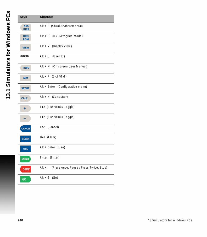
240 13 Simulators for Windows PCs
13
.1 S
imu
lato
rs f
or
Win
do
ws P
Cs
Keys Shortcut
Alt + I (Absolute/Incremental)
Alt + D (DRO/Program mode)
Alt + V (Display View)
<USER> Alt + U (User ID)
Alt + N (On screen User Manual)
Alt + F (Inch/MM)
Alt + Enter (Configuration menu)
Alt + K (Calculator)
F12 (Plus/Minus Toggle)
F12 (Plus/Minus Toggle)
Esc (Cancel)
Del (Clear)
Alt + Enter (Use)
Enter (Enter)
Alt + J (Press once: Pause / Press Twice: Stop)
Alt + S (Go)

ACU-RITE MILLPWRG2 241
13
.1 S
imu
lato
rs f
or
Win
do
ws P
Cs
Numeric, and ARROW keys:
The ARROW keys on a standard PC keyboard will simulate the console ARROW keys, and the number keys will simulate the console number keys (using number lock). When number lock is turned off, the ARROW keys on the number keys (2, 4, 8, 6) will simulate the console ARROW keys.
Soft keys Shortcut
1 F1
2 F2
3 F3
4 F4
5 F5
6 F6
7 F7
8 F8

242 13 Simulators for Windows PCs
13
.2 V
irtu
al
Ma
ch
ine
Sim
ula
tor
So
ftw
are 13.2 Virtual Machine Simulator
Software
Simulation software for R6 and newer
The simulation software for machines running R6 or newer software, provides a convenient way to write part programs and simulate machine behavior using a standard Windows computer. Features and functionality are virtually identical to that of the MILLPWRG2 control itself.
Installation
Installing the Virtual Machine (VM) Simulator is a two step process. First, the VM software is installed and then the MILLPWRG2 software is installed. The VM is installed by launching the setup program and following the installer prompts. On some systems, you may be required to restart the computer after installation before the application will function properly.
Following the initial VM installation, the first startup of the MILLPWRG2 software will automatically update the MILLPWRG2 software within the VM. The installation of the MILLPWRG2 software in the VM is similar to installation of the MILLPWRG2 on the actual control. Follow prompts during the installation and reboot as needed. Once the MILLPWRG2 software is fully installed and running, verify that the MILLPWRG2 software version matches the software version running on your machine console. If the versions do not match, refer to the section “Updating” on page 243.
Operation
The simulator software can be started by using either the "MILLPWR" shortcut created on your desktop during installation or from the Start menu. Once the software is running, it is operated in the same manner as the machine itself. Similarly, it should be shut down using the same sequence of selecting Shutdown and confirming Shutdown at the prompt. Alternatively, a shutdown can be done using the ShutDown button in the Control Panel window. See Control Panel later in this chapter for more details.
Programs created in the simulation software can be copied to the CNC, and (with the correct setup) used on your machine.

ACU-RITE MILLPWRG2 243
13
.2 V
irtu
al
Ma
ch
ine
Sim
ula
tor
So
ftw
areUpdating
MILLPWRG2
Software
The Simulator software itself typically does not need to be updated. Only the MILLPWRG2 application is updated when new releases are available. The same setup.zip used to update the machine software is used to update the simulated software. Although your created part programs will remain intact, it is always recommended to make a backup of your programs and/or configurations before updating the software.
Make sure the MILLPWRG2 software is not running. To update the software, click the "Install" folder shortcut available from the Windows Start Menu, under All Apps and then under ACU-RITE. This will open a folder location in a new Windows Explorer window. Extract the setup.zip and setup.ini files obtained for the software update directly to this folder. Keep the window open. Start the MILLPWRG2 software which will detect that an update is available for installation. Follow the prompts to install the software. When the software update is complete, and prompts to remove any removable drives used for the update, proceed to delete the setup.zip and setup.ini files from the Install folder. If this is not done, the MILLPWRG2 will prompt to update the software on every subsequent startup until the files are manually deleted.
Virtual Machine Simulator
When the Simulator software requires an update, a new version will be made available (for example, v2.0.0). In order to install a new Simulator version, the existing version must first be fully uninstalled (see “Uninstalling,” page 243), and then the new version installed and setup as an initial installation (see “Installation,” page 242). The MILLPWRG2 part programs will be lost during this process, so it is critical to backup these programs prior to uninstalling the existing Simulator.
Uninstalling
Before uninstalling the MILLPWRG2 software, please reboot the Windows PC in order to ensure a successful removal. To remove the MILLPWRG2 software from a Windows PC, either use the Windows Control Panel (Add/Remove Programs, or Programs and Features), or the shortcut "Uninstall MILLPWR" from the Windows Start Menu (in All Programs and under ACU-RITE). When the uninstaller opens, please make sure that all checkboxes are checked so that all components are fully removed from the system.
Caution!
The MILLPWRG2 part programs will be lost during this process. It is critical to backup these programs prior to uninstalling the existing Simulator.

244 13 Simulators for Windows PCs
13
.2 V
irtu
al
Ma
ch
ine
Sim
ula
tor
So
ftw
are Control Panel
The MILLPWRG2 simulator includes a helper application that resides in the Windows taskbar, typically located in the bottom right corner of the desktop screen. Clicking on the AR icon will open the Control Panel window.
The Control Panel provides information about the MILLPWRG2 software, the Virtual Machine itself, and also allows for some user-configurable settings and control operations. There are multiple tabs in the application window:
State
The State tab is the main tab of the Control Panel which shows the current status of the VM and the MILLPWRG2 software. The icon will indicate the state of the software; for example, running or stopped to reflect what is used in the software. The text will indicate the HEROS OS version, the MILLPWRG2 software version, and the IP address.
Display
The Display tab of the Control Panel provides optional display settings. The display resolution default is 1024x768 and must not be changed. The display size default is Normal but can be changed to increase or decrease the size of the display by selecting Scale allowing for manual screen size adjustment, or Full which will scale the display to fill the screen.

ACU-RITE MILLPWRG2 245
13
.2 V
irtu
al
Ma
ch
ine
Sim
ula
tor
So
ftw
areKeypad
The Keypad tab of the Control Panel provides a button to Launch the on-screen keypad application manually if needed.
Hardlock
The Hardlock tab of the Control Panel allows the user to configure the MILLPWRG2 to use a networked USB Protection Module (683049-01, or 683050-01) instead of a single-user local-only key (683048-01). To use a Network Protection Module, check the Use license server box and enter the IP-Address or Hostname of the network server which hosts the Network USB Protection Module. Click Apply to save the changes. Follow prompts to re-start the application as needed.
Network
The Network tab of the Control Panel allows the user to manually assign a unique Hostname to the Virtual Machine, instead of the automatic assignment used by default. To manually set the Hostname, uncheck the Auto Hostname box and enter the IP-Address or Hostname and click Apply to save.

246 13 Simulators for Windows PCs
13
.2 V
irtu
al
Ma
ch
ine
Sim
ula
tor
So
ftw
are NC-Share
The NC-Share tab of the Control Panel allows the user to setup a shared folder between the Windows host PC and the MILLPWRG2 software. This allows easier transfer of NC program files, service files, etc. between the MILLPWRG2 software and the Windows PC. To set up a shared folder, select an available (unused) drive letter to map the shared folder on the Windows PC. Check the Connect NC-Share at startup checkbox if the share should be automatically mounted each time the MILLPWRG2 software is started. Click Connect to save the changes and mount the shared folder. Now you can access the MILLPWRG2 folders using Windows Explorer and the assigned drive letter.
Control buttons
The Restart button will restart the MILLPWRG2 application.
The Stop button will conduct a shutdown of the MILLPWRG2 software and keypad, but will keep the Control Panel application open.
The Shutdown button will conduct a shutdown of the MILLPWRG2 software and keypad, and close the Control Panel application
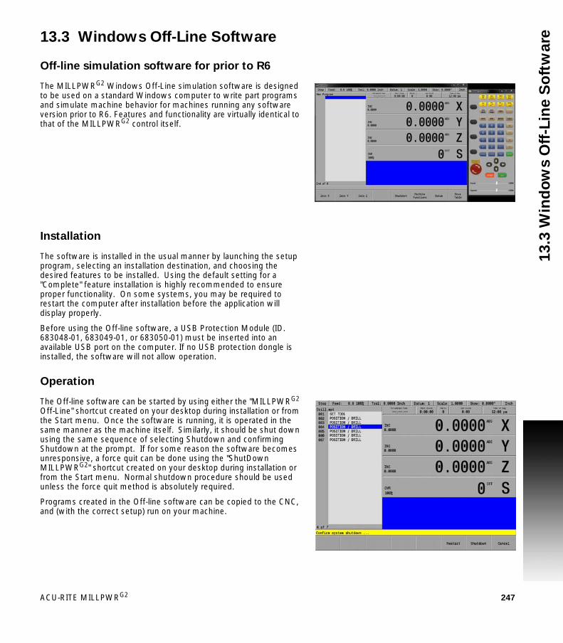
ACU-RITE MILLPWRG2 247
13
.3 W
ind
ow
s O
ff-L
ine
So
ftw
are13.3 Windows Off-Line Software
Off-line simulation software for prior to R6
The MILLPWRG2 Windows Off-Line simulation software is designed to be used on a standard Windows computer to write part programs and simulate machine behavior for machines running any software version prior to R6. Features and functionality are virtually identical to that of the MILLPWRG2 control itself.
Installation
The software is installed in the usual manner by launching the setup program, selecting an installation destination, and choosing the desired features to be installed. Using the default setting for a "Complete" feature installation is highly recommended to ensure proper functionality. On some systems, you may be required to restart the computer after installation before the application will display properly.
Before using the Off-line software, a USB Protection Module (ID. 683048-01, 683049-01, or 683050-01) must be inserted into an available USB port on the computer. If no USB protection dongle is installed, the software will not allow operation.
Operation
The Off-line software can be started by using either the "MILLPWRG2 Off-Line" shortcut created on your desktop during installation or from the Start menu. Once the software is running, it is operated in the same manner as the machine itself. Similarly, it should be shut down using the same sequence of selecting Shutdown and confirming Shutdown at the prompt. If for some reason the software becomes unresponsive, a force quit can be done using the "ShutDown MILLPWRG2" shortcut created on your desktop during installation or from the Start menu. Normal shutdown procedure should be used unless the force quit method is absolutely required.
Programs created in the Off-line software can be copied to the CNC, and (with the correct setup) run on your machine.

248 13 Simulators for Windows PCs
13
.3 W
ind
ow
s O
ff-L
ine
So
ftw
are Updating
It is not necessary to un-install the software before installing updates. Running the new setup program will update the existing installation to the newer version. Although your created part programs will remain intact, it is always recommended to make a backup of your programs and/or configurations before updating the software installation.

ACU-RITE MILLPWRG2 249
Ind
exA
Absolute work piece positions 47Access to Machine Parameter Opera-tions 11Activating/Resetting the Servos 27Advanced Functions
Change Window 119, 120Auxiliary functions 207Axis keys 2
C
Calculator 40, 63, 212Calculator function keys 3Change Window
Folder Contents 121Folder Tree 119, 120Preview Window 120
Changed functions of software 9Clear Program 154Clear Program soft key 92Console 33
Calculator 40Key Pad 42Keyboard 39PGM Mode 34, 78Rear Panel 33
Context Sensitive Help 41Continuous Table Move 49Contours
Circular 170Rectangular 170
Conversational Programming 98Conversational, and G-code format 24Coolant field 207Copy 135Creating a Program 101
D
Data entry keys 2Diameter Offset 73Disengage Z Axis Option 29DRO Mill Cycles 62DRO Mode display 34DRO Operations 60DRO Screen 53
E
Editing the tool table 70Electronic Edge Finder 57Error Log 231E-STOP and Shutdown 26E-Stop button 26
F
Feed Rate 229Feedrate Adjustment 50Find Home 28Find Home feature at start up 25Flood 207Folder View 79Fonts Used in this manual 6Function keys 2
G
G-codeBacking Up a Program 135Definitions 127G-code 124Loading 125Running 125skew feature 58Tool Table 126
G-code and M-Code definitions 127GO hard key 26
I
Incremental work piece positions 47Intended place of operation 6Island 197
Circle Ring 183Custom Pockets 196
J
Job Clock - Parts Counter 230Job Setup 227
K
Keyboard 39Keys on console 2
M
Machine Functions Menu 234Soft keys 234
Message Log 226Message symbols 5Milling and Drilling 156Milling Function Keys 59Milling function keys 3Mist 207Model, software and features 6Move table and navigation keys 3
N
NC software number 6New functions of software 7Numerical keys 2
O
Operating console 33Operating in 2 and 3 Axes Modes 31Operating Modes 37Operating Panel 33
P
Paste 135Peripherals supported 3PGM Mode display 34, 78Potentiometer for feed rate override 3Power supply to the spindle motor 25Powering Up 25Preset Table Move 50Probing 230Program Drawing View 80Program Saving 94Program Steps
2 axes mode on 3 axis systems 322 axis systems 31
Program Steps soft keys 91Programming Introduction 78Pulsed 207
R
Rear Panel 33Recycle Bin 85Re-engaging the Z axis drive 29Reset the E-STOP 27Run Options soft keys 93
S
Save/Discard soft key 92Scale Factor 228Screen Navigation 34Setting the datum 48SetUp 226Setup
DRO mode 37Tool Length 72Tool Table 69
Shut down the system 26Simulation Software for Windows PCs 238
For software prior to R6 247For software R6 and newer 242
Skewing 58Soft keys 2
Calculator( 64) 64Arc Cosine 65Cos 64More Cmds 64
250
Ind
ex Sin 64
Tan 64Clear Program 82Program Functions 82
Change Window 83Exit 83Folder View 83Load 83Program Type 83Save 83
Program Steps 82Circle 91Hole Pattern 91Other Steps 91Position / Milling 91Rectangle 91Tool 91
Run Options 82Dry Run 93Optional Stop 93, 114Single Step 93
Save/Discard 82Shutdown 82Step Functions 82
Change Steps 90Delete Steps 90Explode 89, 90Reverse Path 89, 90, 89, 90Shift Steps 90
Special Characters 39Step Functions soft keys 89, 90STOP hard key 26
T
Teach Position 56Tool Table 68Tool Table Structure 71Tool-Length Offsets 72
U
Updating System Software 236USB Access 95
W
Writing Programs Overview 30
Z
Zeroing an Axis 56


1034384-2J · Ver 19 · 8/2017 · HC · Printed in USA
333 East State ParkwaySchaumburg, IL 60173-5337 USA
HEIDENHAIN CORPORATION
+1 (847) 490-1191+1 (847) 490-3931
E-Mail: [email protected]