Embed Size (px)
Citation preview
DRO 100™
REFERENCE MANUAL
Warranty
ACU-RITE Products and accessories are warranted against defectsin material and workmanship for a period of three years from thedate of purchase. ACU-RITE will, at its option and expense, repairor replace any part of the ACU-RITE product that fails to meet thiswarranty. This warranty covers both materials and factory labor. Inaddition, authorized ACU-RITE service representatives will provideservice labor (field service) for a period of one year at no charge.Notice of the claimed defect must be received by ACU-RITE withinthe warranty period.
This warranty applies only to products and accessories installedand operated in accordance with this reference manual. ACU-RITEshall have no obligation, with respect to any defect or othercondition caused in whole or part by the customer’s incorrect use,improper maintenance, modification of the equipment, or by therepair or maintenance of the product by any person except thosedeemed qualified by ACU-RITE.
Responsibility for loss of operation or diminished performance dueto conditions beyond ACU-RITE’s control cannot be accepted byACU-RITE.
The foregoing warranty obligations are in lieu of all expressed orimplied warranties. ACU-RITE INCORPORATED shall not be liableunder any circumstances for consequential damages.
30 Day Red Carpet Warranty
All ACU-RITE products are covered by a 30-day Red CarpetWarranty. If in the first 30 days this product fails for any reason,repack it in the original packing materials and contact yourAuthorized ACU-RITE Distributor for return procedures.

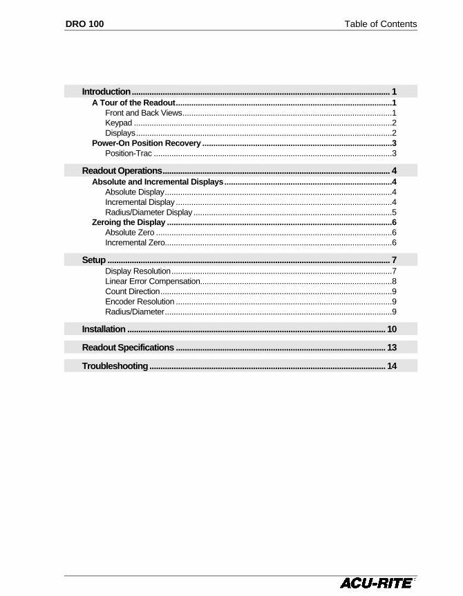
DRO 100 Table of Contents
Introduction..................................................................................................................... 1A Tour of the Readout..................................................................................................1
Front and Back Views...............................................................................................1Keypad .....................................................................................................................2Displays....................................................................................................................2
Power-On Position Recovery ......................................................................................3Position-Trac ............................................................................................................3
Readout Operations....................................................................................................... 4Absolute and Incremental Displays............................................................................4
Absolute Display.......................................................................................................4Incremental Display ..................................................................................................4Radius/Diameter Display ..........................................................................................5
Zeroing the Display ......................................................................................................6Absolute Zero ...........................................................................................................6Incremental Zero.......................................................................................................6
Setup ................................................................................................................................ 7Display Resolution....................................................................................................7Linear Error Compensation.......................................................................................8Count Direction.........................................................................................................9Encoder Resolution ..................................................................................................9Radius/Diameter.......................................................................................................9
Installation ..................................................................................................................... 10
Readout Specifications ............................................................................................... 13
Troubleshooting........................................................................................................... 14
DRO 100
!
This symbol alerts you to the fact thatimportant information concerning theinstallation and operation of this readouthas been included in this manual.
Keep these instructions in a secure placefor future reference.
DRO 100 Introduction
1
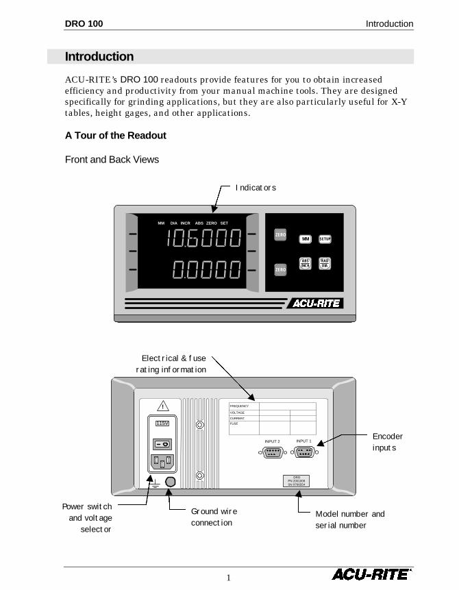
Introduction
ACU-RITE’s DRO 100 readouts provide features for you to obtain increasedefficiency and productivity from your manual machine tools. They are designedspecifically for grinding applications, but they are also particularly useful for X-Ytables, height gages, and other applications.
A Tour of the Readout
Front and Back Views
115V
DROPN 2001009SN 9766554
INPUT 1INPUT 2
FREQUENCY
VOLTAGE
CURRENT
FUSE
!
Power switchand voltage
selector
Encoderinputs
Model number andserial number
Ground wireconnection
Electrical & fuserating information
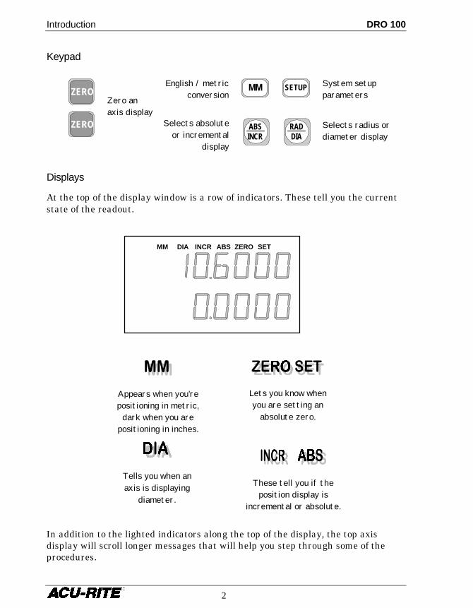
MM DIA INCR ABS ZERO SET
MM SETUP
ABSINCR
ZERO
RADDIA
ZERO
Indicators
Introduction DRO 100
2
Lets you know whenyou are setting an
absolute zero.
Keypad
Displays
At the top of the display window is a row of indicators. These tell you the currentstate of the readout.
In addition to the lighted indicators along the top of the display, the top axisdisplay will scroll longer messages that will help you step through some of theprocedures.
MM DIA INCR ABS ZERO SET
Appears when you’repositioning in metric,
dark when you arepositioning in inches.
These tell you if theposition display is
incremental or absolute.
Tells you when anaxis is displaying
diameter.
ZERO
ZERO
Zero anaxis display
MM SETUP
ABSINCR
RADDIA
English / metricconversion
System setupparameters
Selects absoluteor incremental
display
Selects radius ordiameter display
DRO 100 Introduction
3
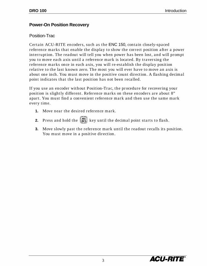
Power-On Position Recovery
Position-Trac
Certain ACU-RITE encoders, such as the ENC 150, contain closely-spacedreference marks that enable the display to show the correct position after a powerinterruption. The readout will tell you when power has been lost, and will promptyou to move each axis until a reference mark is located. By traversing thereference marks once in each axis, you will re-establish the display positionrelative to the last known zero. The most you will ever have to move an axis isabout one inch. You must move in the positive count direction. A flashing decimalpoint indicates that the last position has not been recalled.
If you use an encoder without Position-Trac, the procedure for recovering yourposition is slightly different. Reference marks on these encoders are about 8”apart. You must find a convenient reference mark and then use the same markevery time.
1. Move near the desired reference mark.
2. Press and hold the ABSINCR key until the decimal point starts to flash.
3. Move slowly past the reference mark until the readout recalls its position.You must move in a positive direction.
Readout Operations DRO 100
4
Readout Operations
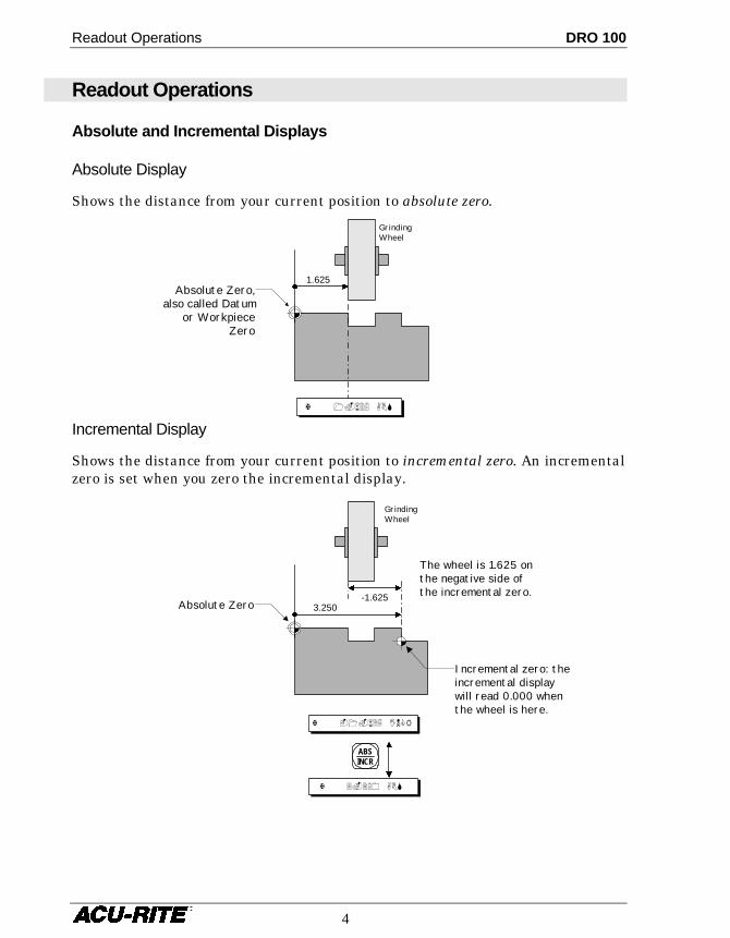
Absolute and Incremental Displays
Absolute Display
Shows the distance from your current position to absolute zero.
Incremental Display
Shows the distance from your current position to incremental zero. An incrementalzero is set when you zero the incremental display.
GrindingWheel
1.625Absolute Zero,
also called Datumor Workpiece
Zero
X 1.625 ABS
GrindingWheel
-1.625Absolute Zero 3.250
Incremental zero: theincremental displaywill read 0.000 whenthe wheel is here.
The wheel is 1.625 onthe negative side ofthe incremental zero.
X -1.625 INCR
X 3.250 ABS
ABSINCR
DRO 100 Readout Operations
5
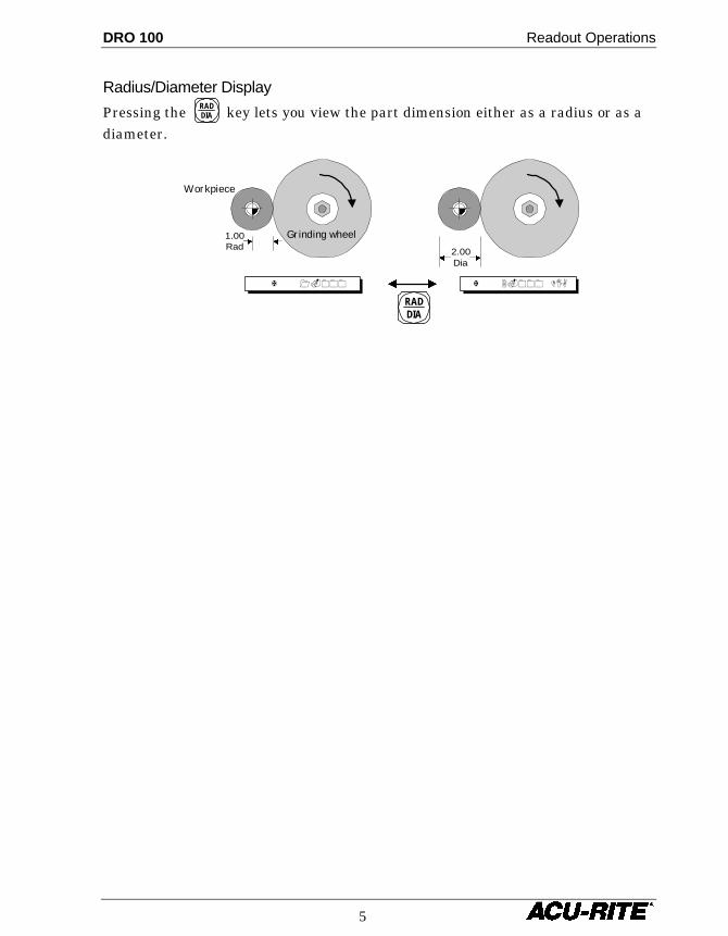
Radius/Diameter Display
Pressing the RADDIA key lets you view the part dimension either as a radius or as a
diameter.
1.00Rad 2.00
Dia
X 1.000
RADDIA
X 2.000 DIA
Grinding wheel
Workpiece
Readout Operations DRO 100
6
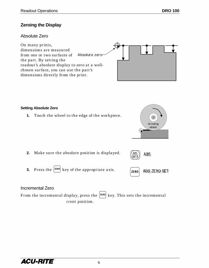
Absolute zero
Zeroing the Display
Absolute Zero
On many prints,dimensions are measuredfrom one or two surfaces ofthe part. By setting thereadout’s absolute display to zero at a well-chosen surface, you can use the part’sdimensions directly from the print.
Setting Absolute Zero
1. Touch the wheel to the edge of the workpiece.
2. Make sure the absolute position is displayed.
3. Press the ZERO key of the appropriate axis.
Incremental Zero
From the incremental display, press the ZERO key. This sets the incrementalrrent position.
ZERO
ABSINCR
Grindingwheel
DRO 100 Setup
7
Setup
The SETUP key lets you change the system parameters. The keys you use to changesetup parameters are different for one-axis and two-axis readouts. To move from
one parameter to the next, press the upper ZERO key (the SETUP key for a single-axisreadout). After the last parameter, the same key ends the setup process and savesany changes.
Some parameters may be set differently for each axis. For these parameters, thedisplay will indicate the axis by number. For example, linear error compensationfactors are indicated by LEC1 for the first axis and LEC2 for the second axis.
Some parameters have choices. Use the lower ZERO key to cycle through these
choices. If you have a single-axis readout, use the only ZERO key whenever the
lower ZERO key is referred to.
Display Resolution
The display resolution will be the same as the encoder resolution. If the jobtolerance is coarser than the encoder resolution (±0.005, for example), you canadjust the display resolution so you won’t be tempted to waste time by machining
to a finer resolution. Use the lower ZERO key to cycle through all the possiblechoices. The choices available depend upon the resolution of your encoders.
Setup DRO 100
8
ZERO
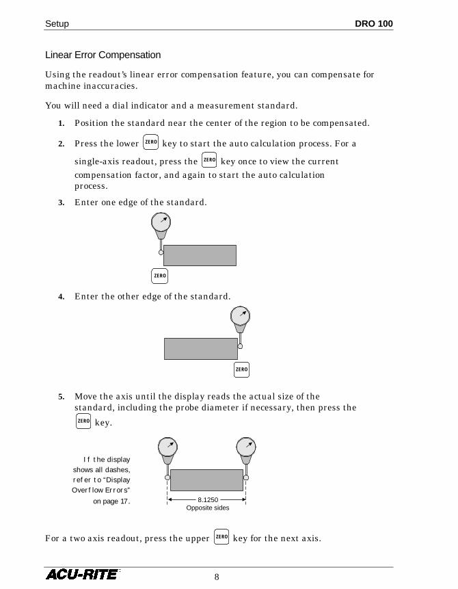
Linear Error Compensation
Using the readout’s linear error compensation feature, you can compensate formachine inaccuracies.
You will need a dial indicator and a measurement standard.
1. Position the standard near the center of the region to be compensated.
2. Press the lower ZERO key to start the auto calculation process. For a
single-axis readout, press the ZERO key once to view the currentcompensation factor, and again to start the auto calculationprocess.
3. Enter one edge of the standard.
4. Enter the other edge of the standard.
5. Move the axis until the display reads the actual size of thestandard, including the probe diameter if necessary, then press the
ZERO key.
For a two axis readout, press the upper ZERO key for the next axis.
ZERO
8.1250Opposite sides
If the displayshows all dashes,refer to “DisplayOverflow Errors”
on page 17.
DRO 100Changing System Parameters
9
Count Direction
This determines which way is positive. Move each axis in the positive countdirection. The display will show a 1 or a 2 depending on count direction. You can
change the count direction by pressing the lower ZERO key.
Encoder Resolution
Move each encoder until the readout senses and displays the resolution. Youshouldn’t have to move more than two inches. For encoders without Position-Trac,
press the lower ZERO key repeatedly until you see the resolution you want.
Radius/Diameter
You can set either axis (or both axes) to display diameter readings when the RADDIA
key is pressed. Use the lower ZERO key to allow (display = 1) or disallow (display =0) diameter display.
Installation DRO 100
10
Installation
Selecting a Location
Selecting a location for the readout is an important consideration for properinstallation. Keep the following points in mind when selecting a safe andconvenient location:
• The readout should be within reach of the operator for easy access to thekeypad.
• The readout should be approximately at eye level.
• Avoid moving components or tools and minimize coolant splash or spray.
• The operating environment must be within the temperature range of 0° to 40°C (32° to 104°F) with a non-condensing relative humidity of 25% to 85%.
Proper Mounting
ACU-RITE has developed special mounting kits for the readout which address themost common mounting requirements. Mounting kits include:
• Column and base machine mountings
• Hardware and mounting instructions
These kits are available from your factory authorized ACU-RITE Distributor orOEM/OEI.
If you fabricate a support device for the readout, it should be large enough andstrong enough to accommodate the readout. It must also be stiff enough tominimize any vibration induced by machinery on the shop floor.
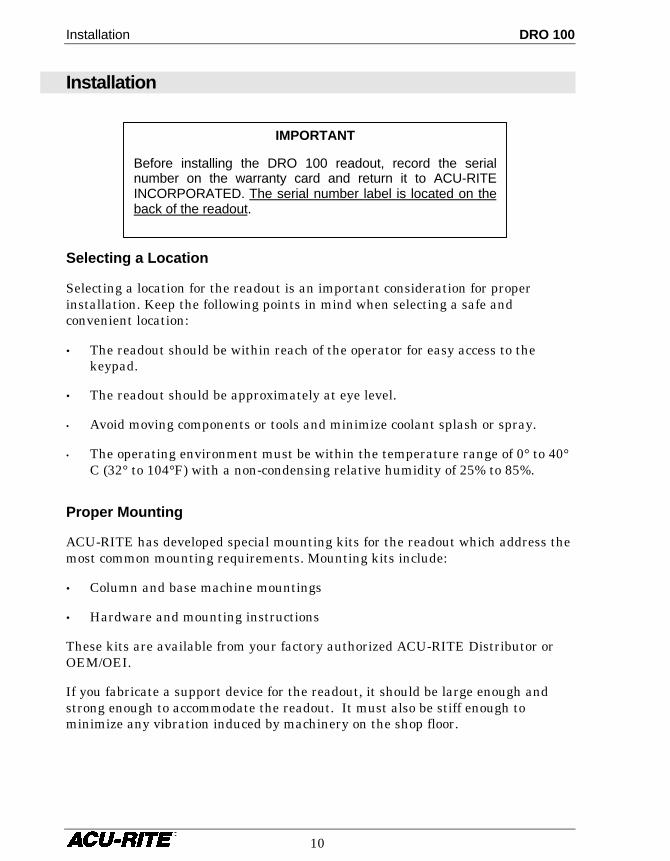
IMPORTANT
Before installing the DRO 100 readout, record the serialnumber on the warranty card and return it to ACU-RITEINCORPORATED. The serial number label is located on theback of the readout.
DRO 100 Installation
11
Connecting the Encoders
Insert the connector from each encoder into the mating connector on the back ofthe readout. Fasten it with a small screwdriver.
Encoder input 1 will be displayed in the readout’s top display and input 2, if any,in the bottom display.
Provide enough slack in the encoder cables to allow for full travel of all machineaxes. Check that machine movements will not pinch the cables. Use the cable tie-down hardware kits supplied with the encoders to fasten the cables neatly to themachine.
Connecting a Ground Wire
Connect a ground wire from the terminal on the back of the readout to themachine. The machine should also be connected to a solid earth ground. If not, besure that the readout is.
Installation DRO 100
12
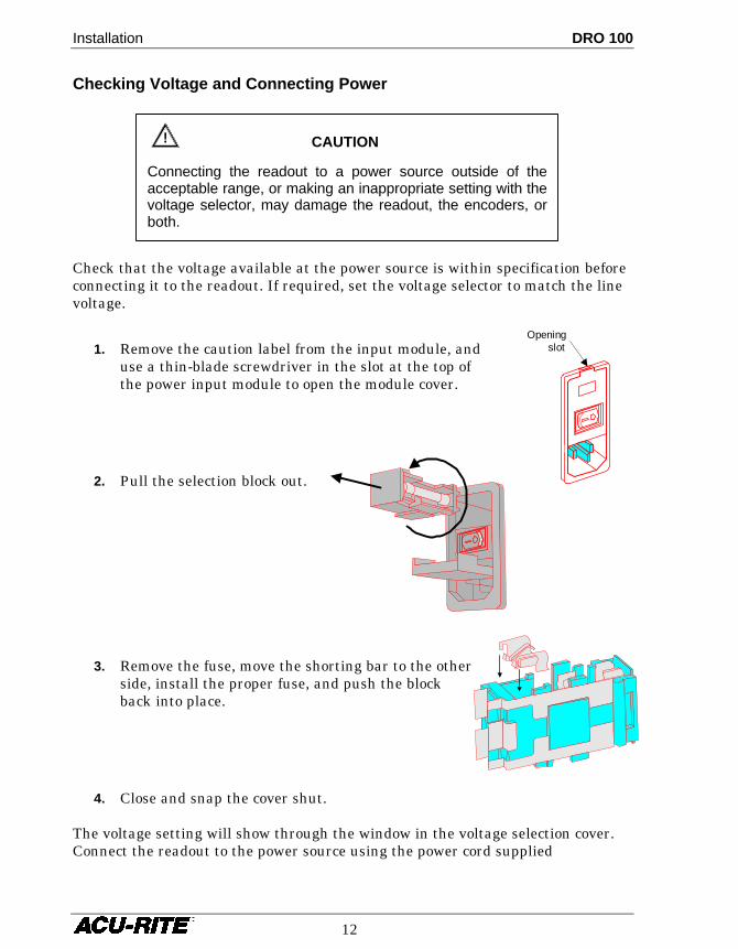
Checking Voltage and Connecting Power
Check that the voltage available at the power source is within specification beforeconnecting it to the readout. If required, set the voltage selector to match the linevoltage.
1. Remove the caution label from the input module, anduse a thin-blade screwdriver in the slot at the top ofthe power input module to open the module cover.
2. Pull the selection block out.
3. Remove the fuse, move the shorting bar to the otherside, install the proper fuse, and push the blockback into place.
4. Close and snap the cover shut.
The voltage setting will show through the window in the voltage selection cover.Connect the readout to the power source using the power cord supplied
Openingslot
! CAUTION
Connecting the readout to a power source outside of theacceptable range, or making an inappropriate setting with thevoltage selector, may damage the readout, the encoders, orboth.
DRO 100 Readout Specifications
13
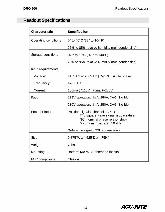
Readout Specifications
Characteristic Specification
Operating conditions 0° to 40°C (32° to 104°F)
25% to 85% relative humidity (non-condensing)
Storage conditions -40° to 60°C (-40° to 140°F)
25% to 95% relative humidity (non-condensing)
Input requirements
Voltage:
Frequency:
Current:
115VAC or 230VAC (+/-20%), single phase
47-63 Hz
150ma @115V, 75ma @230V
Fuse 115V operation: ½ A, 250V, 3AG, Slo-blo
230V operation: ¼ A, 250V, 3AG, Slo-blo
Encoder input Position signals: channels A & BTTL square wave signal in quadrature(90° nominal phase relationship)Maximum input rate: 50 kHz
Reference signal: TTL square wave
Size 9.875”W x 4.625”D x 4.75H”
Weight 7 lbs.
Mounting Bottom: two ¼ -20 threaded inserts
FCC compliance Class A
Troubleshooting DRO 100
14
Troubleshooting
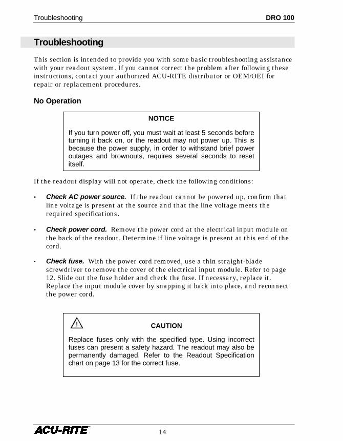
This section is intended to provide you with some basic troubleshooting assistancewith your readout system. If you cannot correct the problem after following theseinstructions, contact your authorized ACU-RITE distributor or OEM/OEI forrepair or replacement procedures.
No Operation
If the readout display will not operate, check the following conditions:
• Check AC power source. If the readout cannot be powered up, confirm thatline voltage is present at the source and that the line voltage meets therequired specifications.
• Check power cord. Remove the power cord at the electrical input module onthe back of the readout. Determine if line voltage is present at this end of thecord.
• Check fuse. With the power cord removed, use a thin straight-bladescrewdriver to remove the cover of the electrical input module. Refer to page12. Slide out the fuse holder and check the fuse. If necessary, replace it.Replace the input module cover by snapping it back into place, and reconnectthe power cord.
! CAUTION
Replace fuses only with the specified type. Using incorrectfuses can present a safety hazard. The readout may also bepermanently damaged. Refer to the Readout Specificationchart on page 13 for the correct fuse.
NOTICE
If you turn power off, you must wait at least 5 seconds beforeturning it back on, or the readout may not power up. This isbecause the power supply, in order to withstand brief poweroutages and brownouts, requires several seconds to resetitself.
DRO 100 Troubleshooting
15
Incorrect Operation
If system positioning does not seem to be repeatable, the problem could be withthe machine tool or with the readout system.
• Check the machine tool. Check that the table is not locked. Check the gibadjustments. Check spindle run-out.
• Check linear encoders. Check each encoder and reading head for properinstallation. Ensure that the mounting brackets are secure.
If the system seems to be displaying incorrect positions, check the following items.
• Verify grinding wheel or tool. Check the grinding wheel or tool for wear.
• Verify linear error compensation. Make sure that the factors used for linearerror compensation are correct.
Power-On Self Test
There are four tests performed when power is applied to the readout. You will notnotice these tests unless a problem is found, in which case a message will scrollacross the display.
Keypad—a key was detected stuck down. The message will display what row (x)and column (y) the stuck key is in:
KEY STUCK – RxCy – PRESS CLEAR
Parameter memory—some of the system setup parameters are not valid. Youmay be able to check and reset these settings, but it’s possible they will be lostagain. The readout should be serviced as soon as possible.
MEMORY FAILURE [1] – PRESS CLEAR
! CAUTION
Some working settings are not valid. Proceed with caution.
Troubleshooting DRO 100
16
Working memory—the memory used by the readout for calculations is faulty.While it may be possible to use the readout, it’s position display and otherinformation will not be reliable.
MEMORY FAILURE [2] – PRESS CLEAR
Program memory—the memory used to store the software is faulty. While itmay be possible to operate the readout, some functions will not work properly andincorrect information may be displayed.
MEMORY FAILURE [3] – PRESS CLEAR
Internal Testing
Several internal tests may be performed to ensure that the readout is functioningproperly. Tests are available for the internal memory, the keypad, and thedisplay. In addition, the testing procedure reports the software version of thereadout.
Begin the internal testing by holding down the RADDIA
key for about 2 seconds.
The software version will appear in the display
Keypad test Begin by pressing the (upper) ZERO key, then press each key (except
the ZERO key) in turn to verify that it is functioning properly. When a key ispressed, the display activates a “plus sign” indicator and increments a count.When you release the key, the plus sign disappears.
! CAUTION
The readout cannot be relied on for correct operation if anymemory failure is indicated. The readout should be servicedimmediately.
! CAUTION
The readout cannot be relied on for correct operation if anymemory failure is indicated. The readout should be servicedimmediately.
DRO 100 Troubleshooting
17
Display test Begin by pressing the ZERO key. All indicators in all displays will
light. Visually check each portion of each display to ensure that they arefunctioning properly.
Press ZERO again to test the display electronics. All decimal points on all displays
will light momentarily, then each segment of all displays will light in turn. PressZERO again, and each digit of all displays will light, one digit at a time, starting
with the leftmost digit and moving to the right.
Exit the diagnostics by pressing the ZERO key.
Other Errors
The readout includes built-in test and error-checking circuitry. This circuitryidentifies errors that occur, and reports the problem to the operator. Errors arereported by scrolling messages in the display.
Loss of power is indicated by the “Power was off” message. Loss of power meansthat power to the readout has been interrupted. Since power to the encoders hasalso been interrupted, positioning information may no longer be accurate. Pressany key to clear the error message. All display measurements will be zeroed.Refer to page 3 for information about position recovery.
Counting errors are indicated by the “Scale miscount” message, telling you inwhich axis the miscount occurred. Counting errors result from distorted electricalsignals from an encoder. These signals can be a result of an encoder malfunction,misalignment, mounting problems, or electrical interference. Press any key toclear the error message. The axis display (for both absolute and incrementalmeasurements) will be zeroed. Follow these steps to determine if your difficultiesare associated with the readout or with the encoder.
• Ensure that the linear encoder connectors are correctly seated.
• Swap linear encoder cables at the readout to see if the problem still appears inthe same display.
• If the problem remains in the same display, the readout is in error.
• If the problem follows the connection change, the linear encoder may be inerror. Refer to the Checking the Linear Encoders section of your encoderreference manual.
Display overflow errors are indicated by dashes in all digits in an axis display.A numeric overflow occurs when the intended measurement is too large for theeight-digit display. Clear the error by returning the machine axis into an area
Troubleshooting DRO 100
18
where measurements can again be displayed, selecting a lower display resolution,or zeroing the display.
This error may also occur when using the automatic compensation routine whilesetting the LEC parameter. An error indicates that the calculated compensationfactor was outside the acceptable range of -9999 to +9999, and usually is theresult of incorrectly entering data. Clear the error and return to the beginning ofthe linear error compensation routine. Refer to page 8.
Data Logging
The readout collects information about itself while it is being used. Thisinformation is stored in memory for review at a later time.
Press and hold the RADDIA key until the software version is displayed. Then press
the SETUP and MM keys simultaneously. Use the ZERO key to cycle through thefollowing information.
Power on time—displayed in decimal hours.
Scale travel distance—the travel distance for each axis is scrolled one after theother.
Last 3 errors—the most recent three errors are remembered and messages forthe errors are scrolled one after the other.

2001-702 EDITION A PRINTED IN USA
ACU-RITE Readout Systems aremanufactured in the USA
ACU-RITE IS AN
ISO 9001CERTIFIED
MANUFACTURER
ACU-RITE INCORPORATEDONE PRECISION WAY
MASON INDUSTRIAL PARKJAMESTOWN, NEW YORK 14701