Embed Size (px)
Citation preview

© 2013 Standard Imaging, Inc. 80678-00, 7/13
3120 Deming Way Middleton WI 53562-1461 USA800-261-4446 . ph 608-831-0025 . fax 608-831-2202 www.standardimaging.com
•User’s Guide to tg-142

User's guide to TG-142
R. K. Fulkerson, Ph.D. and S. M. Holmes, Ph.D.
Contents
1 Introduction 3
2 Daily QA procedures 32.1 Dosimetry . . . . . . . . . . . . . . . . . . . . . . . . . . . . . . . . . . . . . . . . . . . . . . . 3
2.1.1 Photon and electron output constancy . . . . . . . . . . . . . . . . . . . . . . . . . . . 32.2 Mechanical . . . . . . . . . . . . . . . . . . . . . . . . . . . . . . . . . . . . . . . . . . . . . . 3
2.2.1 Optical distance indicator (ODI) at isocenter . . . . . . . . . . . . . . . . . . . . . . . 32.2.2 Lasers . . . . . . . . . . . . . . . . . . . . . . . . . . . . . . . . . . . . . . . . . . . . . 32.2.3 Collimator size indicator . . . . . . . . . . . . . . . . . . . . . . . . . . . . . . . . . . . 4
2.3 Radiation Safety . . . . . . . . . . . . . . . . . . . . . . . . . . . . . . . . . . . . . . . . . . . 42.3.1 Door interlocks . . . . . . . . . . . . . . . . . . . . . . . . . . . . . . . . . . . . . . . . 42.3.2 Door closing safety . . . . . . . . . . . . . . . . . . . . . . . . . . . . . . . . . . . . . . 42.3.3 Audiovisual monitors . . . . . . . . . . . . . . . . . . . . . . . . . . . . . . . . . . . . . 42.3.4 Stereotactic interlocks . . . . . . . . . . . . . . . . . . . . . . . . . . . . . . . . . . . . 42.3.5 Area radiation monitor and beam on indicator . . . . . . . . . . . . . . . . . . . . . . 4
2.4 Daily Wedge QA . . . . . . . . . . . . . . . . . . . . . . . . . . . . . . . . . . . . . . . . . . . 52.5 Daily Imaging QA . . . . . . . . . . . . . . . . . . . . . . . . . . . . . . . . . . . . . . . . . . 5
2.5.1 Planar kV and MV imaging systems and Cone Beam CT (kV and MV) imaging systems 5
3 Weekly MLC QA 63.1 MLC qualitative test (picket fence), travel speed, leaf position accuracy . . . . . . . . . . . . 6
4 Monthly QA procedures 64.1 Dosimetry . . . . . . . . . . . . . . . . . . . . . . . . . . . . . . . . . . . . . . . . . . . . . . . 6
4.1.1 Photon output constancy, electron output constancy, backup monitor chamber, doserate output, and electron beam energy constancy, photon and electron beam pro�leconstancy . . . . . . . . . . . . . . . . . . . . . . . . . . . . . . . . . . . . . . . . . . . 6
4.2 Mechanical . . . . . . . . . . . . . . . . . . . . . . . . . . . . . . . . . . . . . . . . . . . . . . 74.2.1 Light/radiation �eld coincidence, jaw position indicators, and photon beam pro�le
constancy . . . . . . . . . . . . . . . . . . . . . . . . . . . . . . . . . . . . . . . . . . . 74.2.2 Distance check device for lasers compared with front pointer . . . . . . . . . . . . . . 8
1
4.2.3 Localizing lasers . . . . . . . . . . . . . . . . . . . . . . . . . . . . . . . . . . . . . . . 84.2.4 Gantry/collimator angle indicators (@cardinal angles, digital only) . . . . . . . . . . . 84.2.5 Accessory trays . . . . . . . . . . . . . . . . . . . . . . . . . . . . . . . . . . . . . . . . 94.2.6 Cross-hair centering (walkout) and jaw positioning indicators . . . . . . . . . . . . . . 94.2.7 Treatment couch position indicators . . . . . . . . . . . . . . . . . . . . . . . . . . . . 94.2.8 Wedge or compensator placement accuracy . . . . . . . . . . . . . . . . . . . . . . . . 104.2.9 Latching of wedges, blocking tray . . . . . . . . . . . . . . . . . . . . . . . . . . . . . . 10
4.3 Respiratory gating QA . . . . . . . . . . . . . . . . . . . . . . . . . . . . . . . . . . . . . . . . 104.4 Imaging QA . . . . . . . . . . . . . . . . . . . . . . . . . . . . . . . . . . . . . . . . . . . . . . 11
4.4.1 Planar MV imaging systems (EPID) and planar kV imaging systems . . . . . . . . . . 114.4.2 Cone-Beam CT (kV and MV) imaging systems . . . . . . . . . . . . . . . . . . . . . . 12
4.5 Dynamic/universal/virtual wedge QA . . . . . . . . . . . . . . . . . . . . . . . . . . . . . . . 134.5.1 Dynamic/universal/virtual wedge factor for all energies . . . . . . . . . . . . . . . . . 13
4.6 MLC QA . . . . . . . . . . . . . . . . . . . . . . . . . . . . . . . . . . . . . . . . . . . . . . . 144.6.1 Setting versus radiation �eld for two patterns (non-IMRT) . . . . . . . . . . . . . . . . 144.6.2 Backup diaphragm settings (Elekta® machines only) . . . . . . . . . . . . . . . . . . 144.6.3 Leaf position accuracy . . . . . . . . . . . . . . . . . . . . . . . . . . . . . . . . . . . . 14
5 Annual QA procedures 155.1 Dosimetry . . . . . . . . . . . . . . . . . . . . . . . . . . . . . . . . . . . . . . . . . . . . . . . 15
5.1.1 SRS arc rotation mode (range: 0.5 - 10 MU/deg) . . . . . . . . . . . . . . . . . . . . . 155.1.2 Photon and electron output calibration (TG-51), percent depth dose (PDD10) or tissue
maximum ratio (TMR2010) and o�-axis factor (OAF) constancy . . . . . . . . . . . . . 15
5.1.3 Spot check of �eld-size dependent output factors for x rays (two or more �eld sizes),output factors for electron applicators (one more applicator/energy), and physicalwedge transmission factor constancy . . . . . . . . . . . . . . . . . . . . . . . . . . . . 16
5.1.4 Photon monitor unit linearity (output constancy), photon output constancy versusdose rate, electron monitor unit linearity (output constancy) . . . . . . . . . . . . . . 17
5.1.5 Photon output versus gantry angle (including arc modes), electron output versusgantry angle . . . . . . . . . . . . . . . . . . . . . . . . . . . . . . . . . . . . . . . . . 17
5.1.6 Photon and electron OAF constancy versus gantry angle . . . . . . . . . . . . . . . . . 185.2 Mechanical . . . . . . . . . . . . . . . . . . . . . . . . . . . . . . . . . . . . . . . . . . . . . . 19
5.2.1 Collimator rotation isocenter, gantry rotation isocenter, couch rotation isocenter . . . 195.2.2 Electron applicator interlocks . . . . . . . . . . . . . . . . . . . . . . . . . . . . . . . . 205.2.3 Coincidence of radiation and mechanical isocenter . . . . . . . . . . . . . . . . . . . . 205.2.4 Tabletop sag . . . . . . . . . . . . . . . . . . . . . . . . . . . . . . . . . . . . . . . . . 215.2.5 Table angle . . . . . . . . . . . . . . . . . . . . . . . . . . . . . . . . . . . . . . . . . . 21
5.3 MLC QA . . . . . . . . . . . . . . . . . . . . . . . . . . . . . . . . . . . . . . . . . . . . . . . 215.3.1 MLC transmission . . . . . . . . . . . . . . . . . . . . . . . . . . . . . . . . . . . . . . 215.3.2 Leaf position repeatability, Segmental IMRT (step and shoot) test . . . . . . . . . . . 225.3.3 MLC spoke shot . . . . . . . . . . . . . . . . . . . . . . . . . . . . . . . . . . . . . . . 225.3.4 Coincidence of light �eld and radiation �eld (all energies) . . . . . . . . . . . . . . . . 23
5.4 Imaging QA . . . . . . . . . . . . . . . . . . . . . . . . . . . . . . . . . . . . . . . . . . . . . . 235.4.1 Planar MV imaging (EPID) . . . . . . . . . . . . . . . . . . . . . . . . . . . . . . . . . 235.4.2 Planar kV imaging . . . . . . . . . . . . . . . . . . . . . . . . . . . . . . . . . . . . . . 235.4.3 Imaging dose: cone beam CT (kV and MV) . . . . . . . . . . . . . . . . . . . . . . . . 24
5.5 Wedge QA . . . . . . . . . . . . . . . . . . . . . . . . . . . . . . . . . . . . . . . . . . . . . . . 245.5.1 Check of wedge angle for largest wedge, spot check for intermediate angle and �eld size 24
2
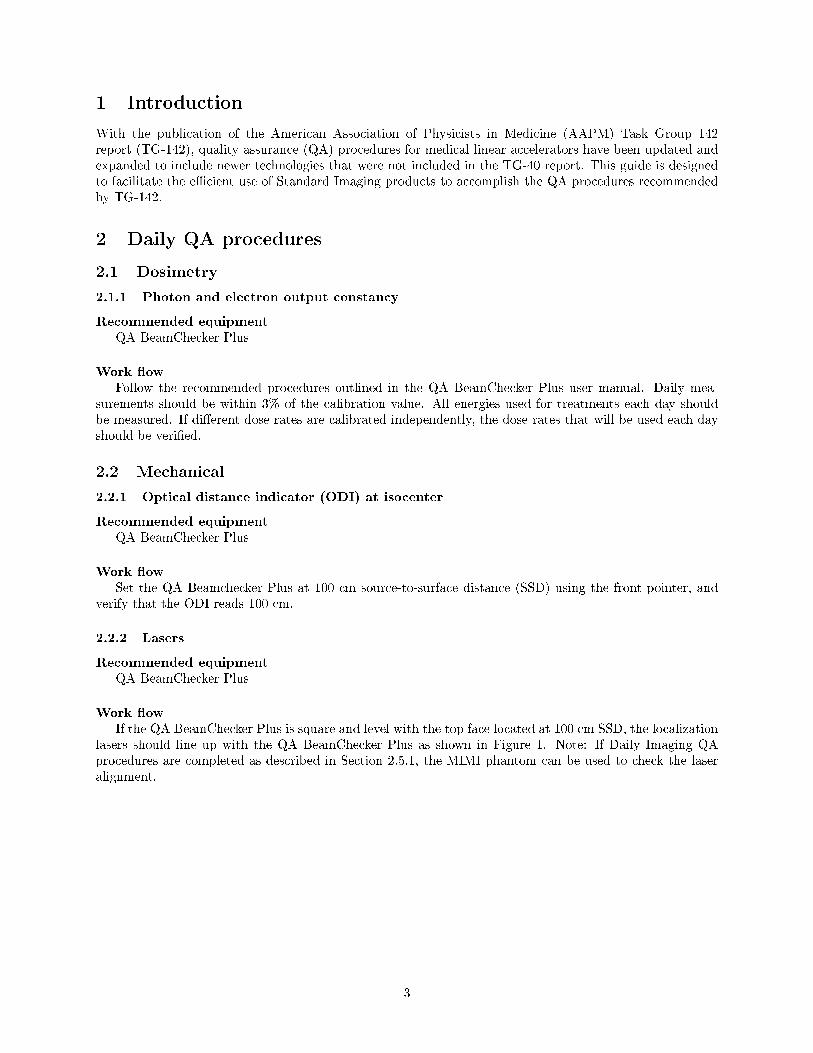
1 Introduction
With the publication of the American Association of Physicists in Medicine (AAPM) Task Group 142report (TG-142), quality assurance (QA) procedures for medical linear accelerators have been updated andexpanded to include newer technologies that were not included in the TG-40 report. This guide is designedto facilitate the e�cient use of Standard Imaging products to accomplish the QA procedures recommendedby TG-142.
2 Daily QA procedures
2.1 Dosimetry
2.1.1 Photon and electron output constancy
Recommended equipmentQA BeamChecker Plus
Work �owFollow the recommended procedures outlined in the QA BeamChecker Plus user manual. Daily mea-
surements should be within 3% of the calibration value. All energies used for treatments each day shouldbe measured. If di�erent dose rates are calibrated independently, the dose rates that will be used each dayshould be veri�ed.
2.2 Mechanical
2.2.1 Optical distance indicator (ODI) at isocenter
Recommended equipmentQA BeamChecker Plus
Work �owSet the QA Beamchecker Plus at 100 cm source-to-surface distance (SSD) using the front pointer, and
verify that the ODI reads 100 cm.
2.2.2 Lasers
Recommended equipmentQA BeamChecker Plus
Work �owIf the QA BeamChecker Plus is square and level with the top face located at 100 cm SSD, the localization
lasers should line up with the QA BeamChecker Plus as shown in Figure 1. Note: If Daily Imaging QAprocedures are completed as described in Section 2.5.1, the MIMI phantom can be used to check the laseralignment.
3
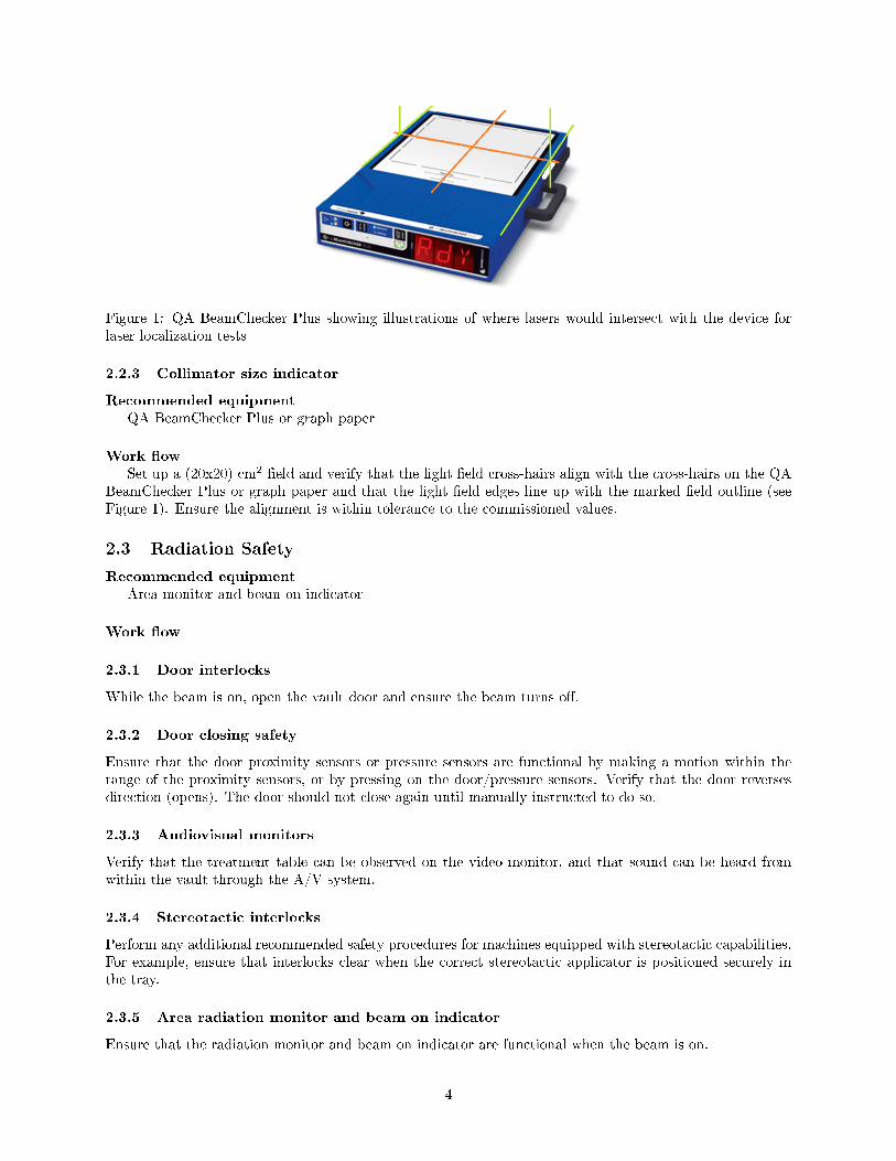
Figure 1: QA BeamChecker Plus showing illustrations of where lasers would intersect with the device forlaser localization tests
2.2.3 Collimator size indicator
Recommended equipmentQA BeamChecker Plus or graph paper
Work �owSet up a (20x20) cm2 �eld and verify that the light �eld cross-hairs align with the cross-hairs on the QA
BeamChecker Plus or graph paper and that the light �eld edges line up with the marked �eld outline (seeFigure 1). Ensure the alignment is within tolerance to the commissioned values.
2.3 Radiation Safety
Recommended equipmentArea monitor and beam on indicator
Work �ow
2.3.1 Door interlocks
While the beam is on, open the vault door and ensure the beam turns o�.
2.3.2 Door closing safety
Ensure that the door proximity sensors or pressure sensors are functional by making a motion within therange of the proximity sensors, or by pressing on the door/pressure sensors. Verify that the door reversesdirection (opens). The door should not close again until manually instructed to do so.
2.3.3 Audiovisual monitors
Verify that the treatment table can be observed on the video monitor, and that sound can be heard fromwithin the vault through the A/V system.
2.3.4 Stereotactic interlocks
Perform any additional recommended safety procedures for machines equipped with stereotactic capabilities.For example, ensure that interlocks clear when the correct stereotactic applicator is positioned securely inthe tray.
2.3.5 Area radiation monitor and beam on indicator
Ensure that the radiation monitor and beam on indicator are functional when the beam is on.
4
2.4 Daily Wedge QA
Recommended equipmentNone
Work �owDeliver a beam with a dynamic wedge (45o recommended) to ensure no interlocks occur.
2.5 Daily Imaging QA
2.5.1 Planar kV and MV imaging systems and Cone Beam CT (kV and MV) imaging systems
Collision interlocks
Recommended equipmentNone
Work �owVerify the machine interlocks are functional by gently depressing the cover on the EPID or imaging
detector and housing.
Positioning/ Repositioning
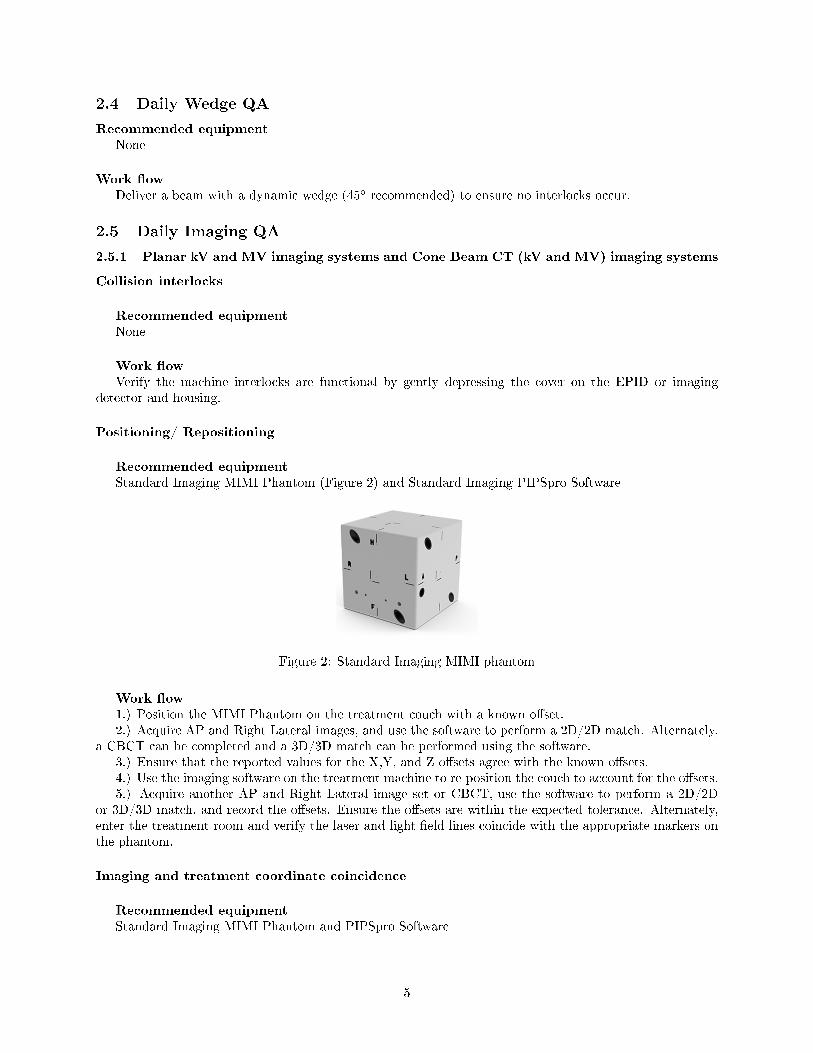
Recommended equipmentStandard Imaging MIMI Phantom (Figure 2) and Standard Imaging PIPSpro Software
Figure 2: Standard Imaging MIMI phantom
Work �ow1.) Position the MIMI Phantom on the treatment couch with a known o�set.2.) Acquire AP and Right Lateral images, and use the software to perform a 2D/2D match. Alternately,
a CBCT can be completed and a 3D/3D match can be performed using the software.3.) Ensure that the reported values for the X,Y, and Z o�sets agree with the known o�sets.4.) Use the imaging software on the treatment machine to re-position the couch to account for the o�sets.5.) Acquire another AP and Right Lateral image set or CBCT, use the software to perform a 2D/2D
or 3D/3D match, and record the o�sets. Ensure the o�sets are within the expected tolerance. Alternately,enter the treatment room and verify the laser and light �eld lines coincide with the appropriate markers onthe phantom.
Imaging and treatment coordinate coincidence
Recommended equipmentStandard Imaging MIMI Phantom and PIPSpro Software
5

Work �ow1.) Position the MIMI Phantom on the treatment couch, aligned to the lasers.2.) Acquire AP and Right Lateral images, and use the software to perform a 2D/2D match. Alternately,
a CBCT can be completed and a 3D/3D match can be performed using the software.3.) Ensure that the location of the center sphere agrees with the isocenter described by the imaging
system within the expected tolerance.
Alternate imaging and treatment coordinate coincidence
Recommended equipmentStandard Imaging MIMI Phantom and PIPSpro Software
Work �ow1.) Acquire a CT scan of the MIMI Phantom with a slice thickness smaller than the TG-142 positioning/re-
positioning tolerance for your machine. Transfer the images to a treatment planning system and delineatethe central aluminum oxide sphere (6.4 mm in diameter) embedded at the center of the phantom, as wellas the bone rods to allow the auto-matching routines to work. The digitally reconstructed radiographs,reference Cone Beam CT and structures will aid in alignment on the imaging system during the QA process.
2.) Set up the phantom on the treatment couch aligned to the treatment lasers. With the EPID,acquire A/P and Right Lateral images. Using the imaging software perform a 2D/2D match with digitallyreconstructed radiographs (DRRs), this tests the congruence between the laser described isocenter and theradiation isocenter. Record the shifts the system recommends in the PIPSpro IGRT module ad ensure theyare within the expected tolerance.
3.) Apply the shifts from Step 2 to position the phantom so that it is correctly aligned to the radiationisocenter.
4.) With the kV imaging system either acquire A/P and Right Lateral images or a full CBCT of thephantom. Using the imaging software, perform a 2D/2D or 3D/3D match with the images from Step 1. Thistests the congruence between the radiation isocenter and the kV imaging isocenter. Record the shifts thatthe system recommends in the PIPSpro IGRT module and ensure they are within the expected tolerance.
3 Weekly MLC QA
3.1 MLC qualitative test (picket fence), travel speed, leaf position accuracy
Recommended equipmentNone
Work �ow1.) Create and deliver a matched segment picket fence test pattern to the EPID imager. Note: �lm can
be used in this test if an EPID is not available.2.) Visually inspect the image for discernible deviations.
4 Monthly QA procedures
4.1 Dosimetry
4.1.1 Photon output constancy, electron output constancy, backup monitor chamber, doserate output, and electron beam energy constancy, photon and electron beam pro�leconstancy
Recommended equipmentIonization chamber (Exradin A18 Ion Chamber), electrometer (MAX 4000 Electrometer or SuperMAX
Electrometer), water tank (DoseView 1D Scanning Arm) or Virtual Water� phantom (Med-Cal, Inc., and
6
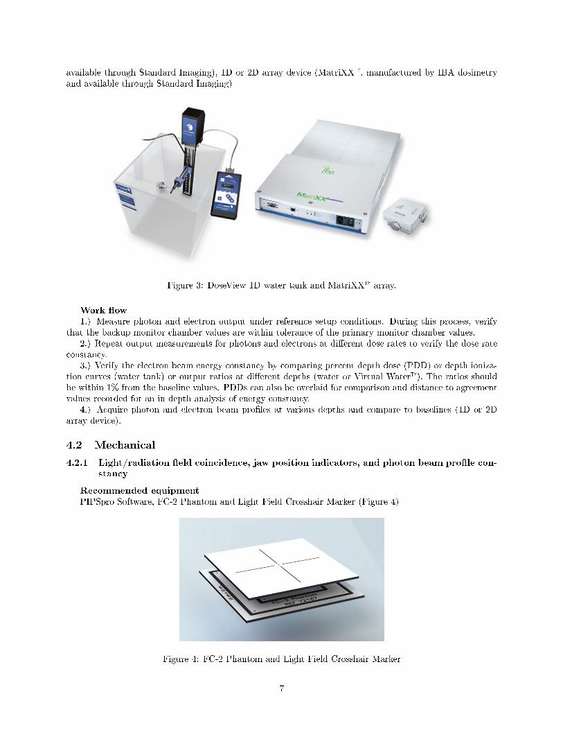
available through Standard Imaging), 1D or 2D array device (MatriXX�, manufactured by IBA dosimetryand available through Standard Imaging)
Figure 3: DoseView 1D water tank and MatriXX� array.
Work �ow1.) Measure photon and electron output under reference setup conditions. During this process, verify
that the backup monitor chamber values are within tolerance of the primary monitor chamber values.2.) Repeat output measurements for photons and electrons at di�erent dose rates to verify the dose rate
constancy.3.) Verify the electron beam energy constancy by comparing percent depth dose (PDD) or depth ioniza-
tion curves (water tank) or output ratios at di�erent depths (water or Virtual Water�). The ratios shouldbe within 1% from the baseline values. PDDs can also be overlaid for comparison and distance to agreementvalues recorded for an in-depth analysis of energy constancy.
4.) Acquire photon and electron beam pro�les at various depths and compare to baselines (1D or 2Darray device).
4.2 Mechanical
4.2.1 Light/radiation �eld coincidence, jaw position indicators, and photon beam pro�le con-stancy
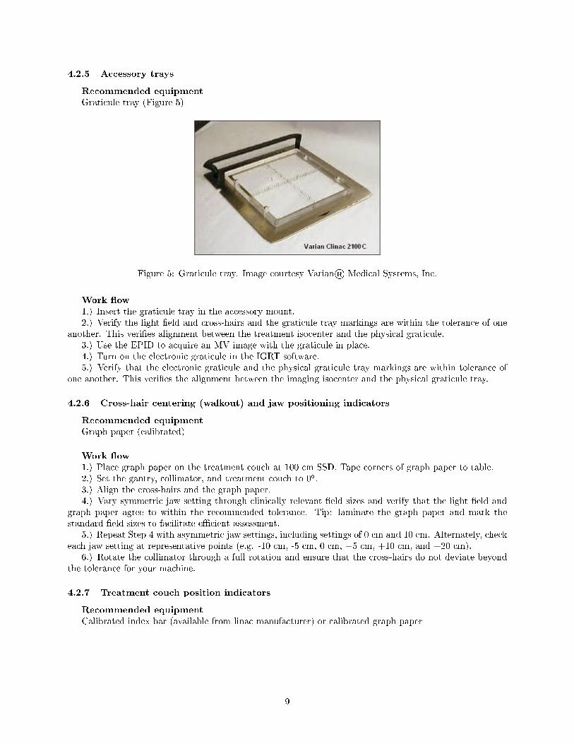
Recommended equipmentPIPSpro Software, FC-2 Phantom and Light Field Crosshair Marker (Figure 4)
Figure 4: FC-2 Phantom and Light Field Crosshair Marker
7

Work �ow1.) Position the FC-2 Phantom on the treatment couch at 100 cm SSD. Using jaw settings of (10x10) cm2
or (15x15) cm2, align the appropriate square on the phantom to the light �eld.2.) Verify that the light �eld aligns with the engraved squares on the phantom. If they do not line up,
adjust the jaws as necessary. This tests the jaw position indicators. Note that PIPSpro Software will alsoreport jaw positions as part of the radiation light �eld analysis.
3.) After the FC-2 Phantom is aligned, the Light Field Crosshair Marker can be placed on top. Ensurethat the FC-2 Phantom is not disturbed when placing the Light Field Crosshair Marker on top with thecross-hair and spherical marker aligned to the center of the light �eld.
4.) Acquire an image and follow the recommended analysis procedures in the radiation light �eld moduleof PIPSpro Software.
5.) Repeat Steps 2-4 with either the (10x10) cm2 or (15x15) cm2 jaw-de�ned �eld that was not completedin Step 1.
4.2.2 Distance check device for lasers compared with front pointer
Recommended equipmentFront pointer, Iso-Align� phantom (manufactured by Civco Medical Solutions and available through
Standard Imaging), Virtual Water� slabs (Med-Cal, Inc., available through Standard Imaging)
Work �ow1.) Position the Iso-Align� phantom at 100 cm using the optical distance indicator (ODI).2.) Verify the laser alignment with the light �eld cross-hairs for gantry angles of 0o, 90o, and 270o. Adjust
lasers if necessary.3.) Check distance to the IsoAlign� phantom with the front pointer. If desired, ensure lasers intersect
at tip of pointer.
4.2.3 Localizing lasers
Recommended equipmentFront pointer, Iso-Align� phantom (manufactured by Civco Medical Solutions and available through
Standard Imaging), Virtual Water� slabs (Med-Cal, Inc., available through Standard Imaging)
Work �ow1.) Without touching the setup from 4.2.2, verify that all room lasers are within expected tolerances.
4.2.4 Gantry/collimator angle indicators (@cardinal angles, digital only)
Recommended equipmentDigital or bubble level
Work �ow1.) Place the level on a �at surface of the gantry head and compare the level readout with the gantry
readout at all four cardinal angles.2.) With the gantry at 90oor 270o, rotate the collimator to each of the four cardinal angles, place the
level on a machined edge of the collimator housing and ensure that the level agrees within tolerance to thecollimator readout.
3.) For a bubble level, set the gantry or collimator such that the bubble indicates it is level, then readthe gantry angle.
8
4.2.5 Accessory trays
Recommended equipmentGraticule tray (Figure 5)
Figure 5: Graticule tray. Image courtesy Varian® Medical Systems, Inc.
Work �ow1.) Insert the graticule tray in the accessory mount.2.) Verify the light �eld and cross-hairs and the graticule tray markings are within the tolerance of one
another. This veri�es alignment between the treatment isocenter and the physical graticule.3.) Use the EPID to acquire an MV image with the graticule in place.4.) Turn on the electronic graticule in the IGRT software.5.) Verify that the electronic graticule and the physical graticule tray markings are within tolerance of
one another. This veri�es the alignment between the imaging isocenter and the physical graticule tray.
4.2.6 Cross-hair centering (walkout) and jaw positioning indicators
Recommended equipmentGraph paper (calibrated)
Work �ow1.) Place graph paper on the treatment couch at 100 cm SSD. Tape corners of graph paper to table.2.) Set the gantry, collimator, and treatment couch to 0o.3.) Align the cross-hairs and the graph paper.4.) Vary symmetric jaw setting through clinically relevant �eld sizes and verify that the light �eld and
graph paper agree to within the recommended tolerance. Tip: laminate the graph paper and mark thestandard �eld sizes to facilitate e�cient assessment.
5.) Repeat Step 4 with asymmetric jaw settings, including settings of 0 cm and 10 cm. Alternately, checkeach jaw setting at representative points (e.g. -10 cm, -5 cm, 0 cm, +5 cm, +10 cm, and +20 cm).
6.) Rotate the collimator through a full rotation and ensure that the cross-hairs do not deviate beyondthe tolerance for your machine.
4.2.7 Treatment couch position indicators
Recommended equipmentCalibrated index bar (available from linac manufacturer) or calibrated graph paper
9

Work �ow (index bar)1.) Position treatment couch at isocenter with the indexing bar latched at the 0 position on the couch.2.) Align the center of the indexing bar with the cross-hairs.3.) Verify that the couch readout is 0 cm lateral, 0 cm vertical, and 0 cm longitudinal or within tolerance.
Alternately, check that the couch is within the expected tolerance, then set the couch readout to 0 cm, 0 cm,0 cm to check relative shifts.
4.) Move the couch laterally to a preset demarcation (established during commissioning) and verify thatthe couch readout is within tolerance relative to baseline values.
5.) Move the indexing bar to a di�erent position on the treatment couch.6.) Move the couch longitudinally until the indexing bar and cross-hairs align. Verify that the longitudinal
o�set is within tolerance.7.) Move the couch vertically to locate the laser on the side of the couch. Shift the couch up or down a
set distance and measure the distance with a rule. Ensure the couch readout is within tolerance relative tothe measured and/or baseline values.
8.) Rotate the couch by a known o�set (established during commissioning) and verify that the couchreadout is within tolerance relative to baseline values.
Work �ow (calibrated graph paper)1.) Assuming the graph paper used for testing cross-hair centering is still in place, shift the couch in,
out, left and right by known distances. Verify the couch readout is within tolerance of the known shifts.2.) Mark the location of the laser on the side of the couch then shift the couch up or down a set distance.3.) Verify by measuring the distance between the mark and the laser.4.) Rotate the couch ±90oand verify cross-hair alignment with the paper lines5.) Pick a known location on the couch (a bolt head works well) and verify that when the front pointer
is aligned to the chosen location, the couch position readout matches the baseline values.
4.2.8 Wedge or compensator placement accuracy
Recommended equipmentRuler
Work �ow1.) Set the gantry and collimator to 0o. Set the couch surface at 100 cm SSD. Mark the center of the
cross-hairs (used as a reference point for measurements) on piece of tape placed on the couch.2.) Insert each wedge into the accessory tray and turn on the light �eld. Open the jaws wider than the
wedge.3.) Measure the distance from isocenter to the edge of the shadow and verify that the distance is within
the wedge placement tolerances.
4.2.9 Latching of wedges, blocking tray
Recommended equipmentWedges and block trays used with the linac
Work �ow1.) Visually inspect each wedge tray for loose screws, missing parts, and mechanical defects.2.) Insert a wedge or block tray into the accessory tray and verify that it latches correctly.
4.3 Respiratory gating QA
Recommend equipmentRespiratory Gating Platform, IMRT Dose Veri�cation Phantom, Exradin A1SL Ion Chamber, MAX 4000
Electrometer or SuperMAX Electrometer (Figure 6)
10
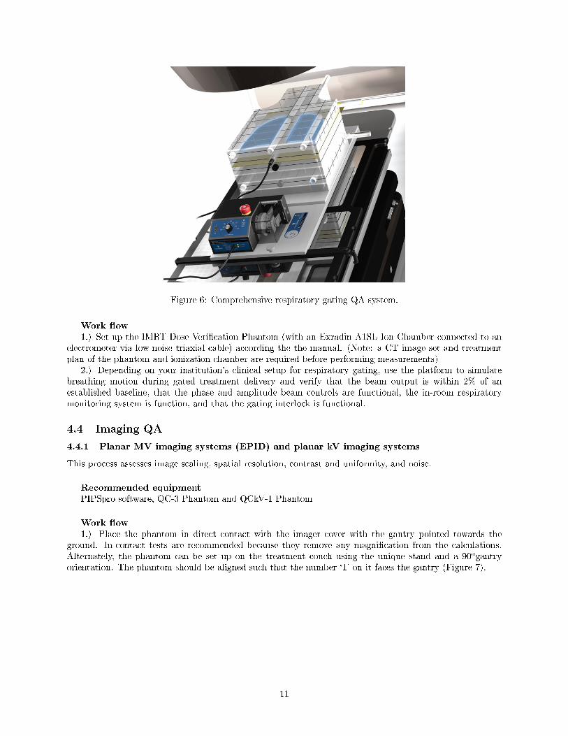
Figure 6: Comprehensive respiratory gating QA system.
Work �ow1.) Set up the IMRT Dose Veri�cation Phantom (with an Exradin A1SL Ion Chamber connected to an
electrometer via low-noise triaxial cable) according the the manual. (Note: a CT image set and treatmentplan of the phantom and ionization chamber are required before performing measurements)
2.) Depending on your institution's clinical setup for respiratory gating, use the platform to simulatebreathing motion during gated treatment delivery and verify that the beam output is within 2% of anestablished baseline, that the phase and amplitude beam controls are functional, the in-room respiratorymonitoring system is function, and that the gating interlock is functional.
4.4 Imaging QA
4.4.1 Planar MV imaging systems (EPID) and planar kV imaging systems
This process assesses image scaling, spatial resolution, contrast and uniformity, and noise.
Recommended equipmentPIPSpro software, QC-3 Phantom and QCkV-1 Phantom
Work �ow1.) Place the phantom in direct contact with the imager cover with the gantry pointed towards the
ground. In-contact tests are recommended because they remove any magni�cation from the calculations.Alternately, the phantom can be set up on the treatment couch using the unique stand and a 90ogantryorientation. The phantom should be aligned such that the number `1' on it faces the gantry (Figure 7).
11
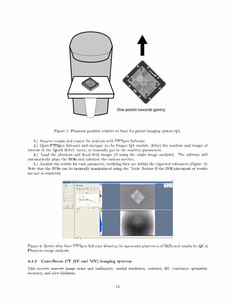
Figure 7: Phantom position relative to linac for planar imaging system QA.
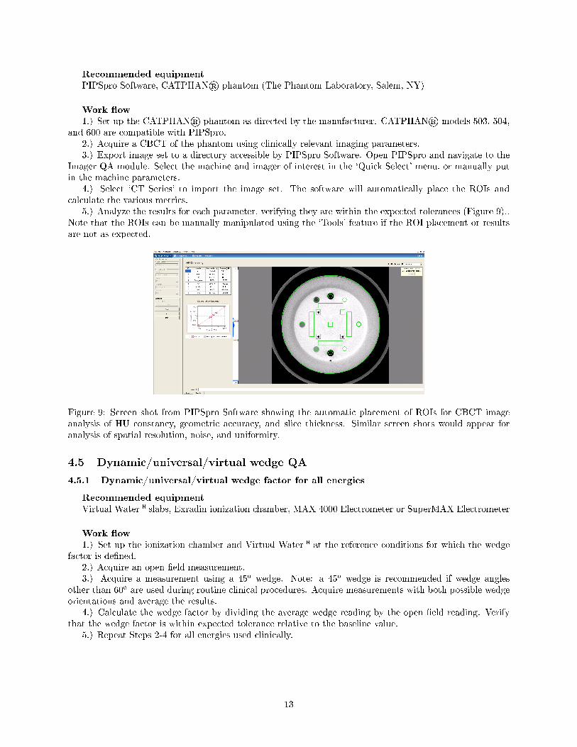
2.) Acquire images and export for analysis with PIPSpro Software.3.) Open PIPSpro Software and navigate to the Imager QA module. Select the machine and imager of
interest in the `Quick Select' menu, or manually put in the machine parameters.4.) Load the phantom and �ood �eld images (if using the single image analysis). The software will
automatically place the ROIs and calculate the various metrics.5.) Analyze the results for each parameter, verifying they are within the expected tolerances (Figure .8)
Note that the ROIs can be manually manipulated using the `Tools' feature if the ROI placement or resultsare not as expected.
Figure 8: Screen shot from PIPSpro Software showing the automatic placement of ROIs and results for QC-3Phantom image analysis.
4.4.2 Cone-Beam CT (kV and MV) imaging systems
This process assesses image noise and uniformity, spatial resolution, contrast, HU constancy, geometricaccuracy, and slice thickness
12
Recommended equipmentPIPSpro Software, CATPHAN® phantom (The Phantom Laboratory, Salem, NY)
Work �ow1.) Set up the CATPHAN® phantom as directed by the manufacturer. CATPHAN® models 503, 504,
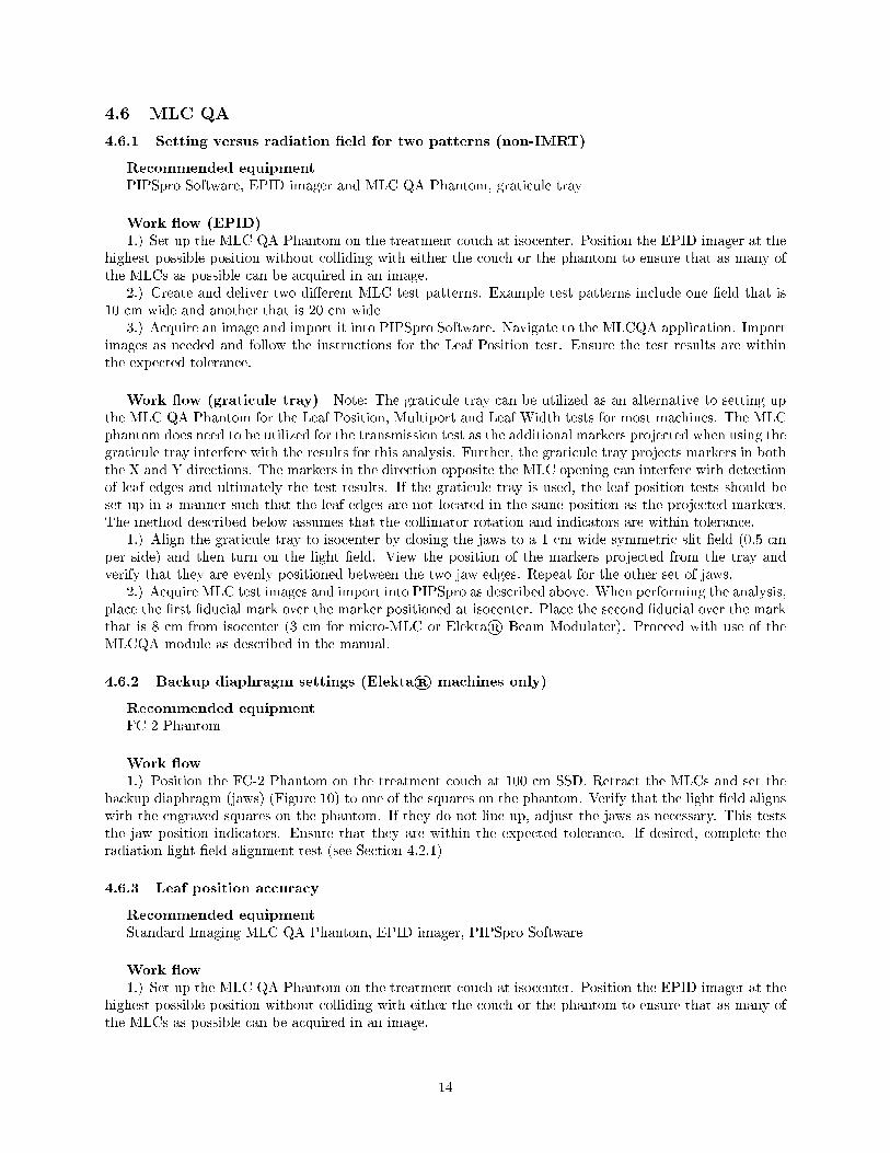
and 600 are compatible with PIPSpro.2.) Acquire a CBCT of the phantom using clinically relevant imaging parameters.3.) Export image set to a directory accessible by PIPSpro Software. Open PIPSpro and navigate to the
Imager QA module. Select the machine and imager of interest in the `Quick Select' menu, or manually putin the machine parameters.
4.) Select `CT Series' to import the image set. The software will automatically place the ROIs andcalculate the various metrics.
5.) Analyze the results for each parameter, verifying they are within the expected tolerances (Figure 9)..Note that the ROIs can be manually manipulated using the `Tools' feature if the ROI placement or resultsare not as expected.
Figure 9: Screen shot from PIPSpro Software showing the automatic placement of ROIs for CBCT imageanalysis of HU constancy, geometric accuracy, and slice thickness. Similar screen shots would appear foranalysis of spatial resolution, noise, and uniformity.
4.5 Dynamic/universal/virtual wedge QA
4.5.1 Dynamic/universal/virtual wedge factor for all energies
Recommended equipmentVirtual Water� slabs, Exradin ionization chamber, MAX 4000 Electrometer or SuperMAX Electrometer
Work �ow1.) Set up the ionization chamber and Virtual Water� at the reference conditions for which the wedge
factor is de�ned.2.) Acquire an open �eld measurement.3.) Acquire a measurement using a 45o wedge. Note: a 45o wedge is recommended if wedge angles
other than 60o are used during routine clinical procedures. Acquire measurements with both possible wedgeorientations and average the results.
4.) Calculate the wedge factor by dividing the average wedge reading by the open �eld reading. Verifythat the wedge factor is within expected tolerance relative to the baseline value.
5.) Repeat Steps 2-4 for all energies used clinically.
13
4.6 MLC QA
4.6.1 Setting versus radiation �eld for two patterns (non-IMRT)
Recommended equipmentPIPSpro Software, EPID imager and MLC QA Phantom, graticule tray
Work �ow (EPID)1.) Set up the MLC QA Phantom on the treatment couch at isocenter. Position the EPID imager at the
highest possible position without colliding with either the couch or the phantom to ensure that as many ofthe MLCs as possible can be acquired in an image.
2.) Create and deliver two di�erent MLC test patterns. Example test patterns include one �eld that is10 cm wide and another that is 20 cm wide
3.) Acquire an image and import it into PIPSpro Software. Navigate to the MLCQA application. Importimages as needed and follow the instructions for the Leaf Position test. Ensure the test results are withinthe expected tolerance.
Work �ow (graticule tray) Note: The graticule tray can be utilized as an alternative to setting upthe MLC QA Phantom for the Leaf Position, Multiport and Leaf Width tests for most machines. The MLCphantom does need to be utilized for the transmission test as the additional markers projected when using thegraticule tray interfere with the results for this analysis. Further, the graticule tray projects markers in boththe X and Y directions. The markers in the direction opposite the MLC opening can interfere with detectionof leaf edges and ultimately the test results. If the graticule tray is used, the leaf position tests should beset up in a manner such that the leaf edges are not located in the same position as the projected markers.The method described below assumes that the collimator rotation and indicators are within tolerance.
1.) Align the graticule tray to isocenter by closing the jaws to a 1 cm wide symmetric slit �eld (0.5 cmper side) and then turn on the light �eld. View the position of the markers projected from the tray andverify that they are evenly positioned between the two jaw edges. Repeat for the other set of jaws.
2.) Acquire MLC test images and import into PIPSpro as described above. When performing the analysis,place the �rst �ducial mark over the marker positioned at isocenter. Place the second �ducial over the markthat is 8 cm from isocenter (3 cm for micro-MLC or Elekta® Beam Modulater). Proceed with use of theMLCQA module as described in the manual.
4.6.2 Backup diaphragm settings (Elekta® machines only)
Recommended equipmentFC-2 Phantom
Work �ow1.) Position the FC-2 Phantom on the treatment couch at 100 cm SSD. Retract the MLCs and set the
backup diaphragm (jaws) (Figure 10) to one of the squares on the phantom. Verify that the light �eld alignswith the engraved squares on the phantom. If they do not line up, adjust the jaws as necessary. This teststhe jaw position indicators. Ensure that they are within the expected tolerance. If desired, complete theradiation light �eld alignment test (see Section 4.2.1)
4.6.3 Leaf position accuracy
Recommended equipmentStandard Imaging MLC QA Phantom, EPID imager, PIPSpro Software
Work �ow1.) Set up the MLC QA Phantom on the treatment couch at isocenter. Position the EPID imager at the
highest possible position without colliding with either the couch or the phantom to ensure that as many ofthe MLCs as possible can be acquired in an image.
14
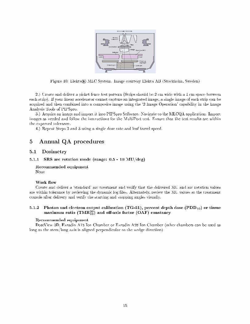
Figure 10: Elekta® MLC System. Image courtesy Elekta AB (Stockholm, Sweden)
2.) Create and deliver a picket fence test pattern (Strips should be 2 cm wide with a 1 cm space betweeneach strip). If your linear accelerator cannot capture an integrated image, a single image of each strip can beacquired and then combined into a composite image using the `2 Image Operation' capability in the ImageAnalysis Tools of PIPSpro.
3.) Acquire an image and import it into PIPSpro Software. Navigate to the MLCQA application. Importimages as needed and follow the instructions for the MultiPort test. Ensure that the test results are withinthe expected tolerance.
4.) Repeat Steps 2 and 3 using a single dose rate and leaf travel speed.
5 Annual QA procedures
5.1 Dosimetry
5.1.1 SRS arc rotation mode (range: 0.5 - 10 MU/deg)
Recommended equipmentNone
Work �owCreate and deliver a `standard' arc treatment and verify that the delivered MU and arc rotation values
are within tolerance by reviewing the dynamic log �les. Alternately, review the MU values at the treatmentconsole after delivery and verify the starting and stopping angles visually.
5.1.2 Photon and electron output calibration (TG-51), percent depth dose (PDD10) or tissuemaximum ratio (TMR20
10) and o�-axis factor (OAF) constancy
Recommended equipmentDoseView 3D, Exradin A18 Ion Chamber or Exradin A28 Ion Chamber (other chambers can be used as
long as the stem/long axis is aligned perpendicular to the wedge direction)
15
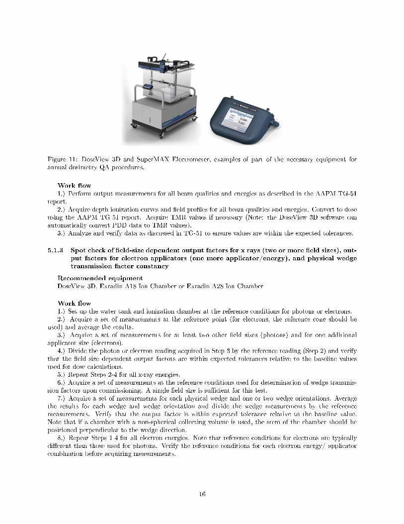
Figure 11: DoseView 3D and SuperMAX Electrometer, examples of part of the necessary equipment forannual dosimetry QA procedures.
Work �ow1.) Perform output measurements for all beam qualities and energies as described in the AAPM TG-51
report.2.) Acquire depth ionization curves and �eld pro�les for all beam qualities and energies. Convert to dose
using the AAPM TG-51 report. Acquire TMR values if necessary (Note: the DoseView 3D software canautomatically convert PDD data to TMR values).
3.) Analyze and verify data as discussed in TG-51 to ensure values are within the expected tolerances.
5.1.3 Spot check of �eld-size dependent output factors for x rays (two or more �eld sizes), out-put factors for electron applicators (one more applicator/energy), and physical wedgetransmission factor constancy
Recommended equipmentDoseView 3D, Exradin A18 Ion Chamber or Exradin A28 Ion Chamber
Work �ow1.) Set up the water tank and ionization chamber at the reference conditions for photons or electrons.2.) Acquire a set of measurements at the reference point (for electrons, the reference cone should be
used) and average the results.3.) Acquire a set of measurements for at least two other �eld sizes (photons) and for one additional
applicator size (electrons).4.) Divide the photon or electron reading acquired in Step 3 by the reference reading (Step 2) and verify
that the �eld size dependent output factors are within expected tolerances relative to the baseline valuesused for dose calculations.
5.) Repeat Steps 2-4 for all x-ray energies.6.) Acquire a set of measurements at the reference conditions used for determination of wedge transmis-
sion factors upon commissioning. A single �eld size is su�cient for this test.7.) Acquire a set of measurements for each physical wedge and one or two wedge orientations. Average
the results for each wedge and wedge orientation and divide the wedge measurements by the referencemeasurements. Verify that the output factor is within expected tolerance relative to the baseline value.Note that if a chamber with a non-spherical collecting volume is used, the stem of the chamber should bepositioned perpendicular to the wedge direction.
8.) Repeat Steps 1-4 for all electron energies. Note that reference conditions for electrons are typicallydi�erent than those used for photons. Verify the reference conditions for each electron energy/ applicatorcombination before acquiring measurements.
16

5.1.4 Photon monitor unit linearity (output constancy), photon output constancy versus doserate, electron monitor unit linearity (output constancy)
Recommended equipmentVirtual Water� slabs, DoseView 1D or DoseView 3D, Exradin ionization chamber, MAX 4000 Electrom-
eter or SuperMAX Electrometer
Work �ow1.) Set up the Virtual Water� (or water tank) and ion chamber at the machine-speci�c reference condi-
tions.2.) Deliver a set number of monitor units (suggested value: 400 MU) with a clinically relevant dose rate
and record the chamber measurement.3.) Using the same setup conditions, deliver a fraction of the MU used in Step 2 (suggested value:
100 MU) using the same dose rate and record the chamber measurement.4.) Verify that the reading in Step 3 is the desired fraction of the value in Step 2. Example: 100 MU
reading is one-quarter of the 400 MU reading and is within the expected tolerance.5.) Deliver a smaller fraction of the MU delivered in Step 3 (suggested value: 2 MU) using the same dose
rate and verify that the reading is the desired fraction of the value in Step 3. Example: 2 MU reading isone-�ftieth the 100 MU reading and is within the expected tolerance. Note that the MU values chosen forSteps 2-5 should span those used clinically (e.g. 1 MU for IMRT segments or 3000 MU for an SRS or totalbody irradiation (TBI) treatment).
6.) Deliver a set number of monitor units (suggested value: 100 MU) with other clinically relevant doserates, and verify that each delivery results in readings that are equal to one another to within the expectedtolerance.
7.) Repeat Steps 2-6 for all photon energies.8.) Shift the depth of the ionization chamber to a reasonable depth for electrons (near dmax). Change
beam settings to deliver electrons.9.) Deliver a set number of monitor units (suggested value: 400 MU) with a clinically relevant dose rate
and record the chamber measurement.10.) Using the same setup conditions, deliver a fraction of the MU used in Step 9 (suggested value:
100 MU) using the same dose rate and record the chamber measurement.11.) Verify that the reading in Step 10 is the desired fraction of the value in Step 9. Example: 100 MU
reading is one-quarter of the 400 MU reading and is within the expected tolerance.12.) Repeat Steps 9-11 for all electron energies. The MU values chosen for output constancy measure-
ments should span the clinically used values.13.) Dose rates for electron should also be veri�ed if multiple options exist.
5.1.5 Photon output versus gantry angle (including arc modes), electron output versus gantryangle
Recommended equipmentExradin ionization chamber (with In-Air Comparison Jig) or Lucy 3D QA Phantom (optional) (Fig-
ure 12), MAX 4000 Electrometer or SuperMAX Electrometer
17
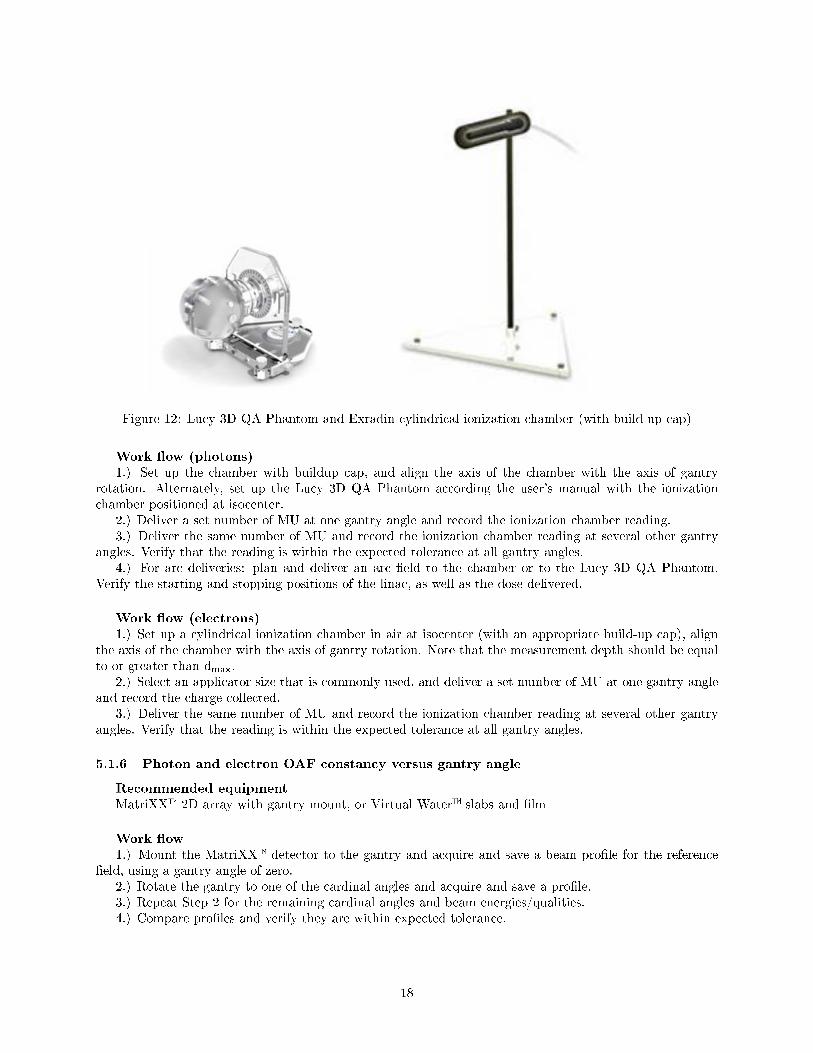
Figure 12: Lucy 3D QA Phantom and Exradin cylindrical ionization chamber (with build-up cap)
Work �ow (photons)1.) Set up the chamber with buildup cap, and align the axis of the chamber with the axis of gantry
rotation. Alternately, set up the Lucy 3D QA Phantom according the user's manual with the ionizationchamber positioned at isocenter.
2.) Deliver a set number of MU at one gantry angle and record the ionization chamber reading.3.) Deliver the same number of MU and record the ionization chamber reading at several other gantry
angles. Verify that the reading is within the expected tolerance at all gantry angles.4.) For arc deliveries: plan and deliver an arc �eld to the chamber or to the Lucy 3D QA Phantom.
Verify the starting and stopping positions of the linac, as well as the dose delivered.
Work �ow (electrons)1.) Set up a cylindrical ionization chamber in air at isocenter (with an appropriate build-up cap), align
the axis of the chamber with the axis of gantry rotation. Note that the measurement depth should be equalto or greater than dmax.
2.) Select an applicator size that is commonly used, and deliver a set number of MU at one gantry angleand record the charge collected.
3.) Deliver the same number of MU and record the ionization chamber reading at several other gantryangles. Verify that the reading is within the expected tolerance at all gantry angles.
5.1.6 Photon and electron OAF constancy versus gantry angle
Recommended equipmentMatriXX� 2D array with gantry mount, or Virtual Water� slabs and �lm
Work �ow1.) Mount the MatriXX� detector to the gantry and acquire and save a beam pro�le for the reference
�eld, using a gantry angle of zero.2.) Rotate the gantry to one of the cardinal angles and acquire and save a pro�le.3.) Repeat Step 2 for the remaining cardinal angles and beam energies/qualities.4.) Compare pro�les and verify they are within expected tolerance.
18
Alternate work �ow using Virtual Water� and �lm1.) Set up Virtual Water� slabs such that a piece of �lm is positioned at the reference depth (ensuring
adequate buildup and backscatter are present). The �lm should be perpendicular to the central axis of thebeam.
2.) Irradiate �lm with the reference �eld size to acquire a �eld pro�le using a gantry angle of zero.3.) Repeat Steps 1 and 2 for the remaining cardinal angles and beam energies/qualities.4.) Compare scanned �lm pro�les and verify they are within expected tolerance.
5.2 Mechanical
5.2.1 Collimator rotation isocenter, gantry rotation isocenter, couch rotation isocenter
Recommended equipmentFilm (radiographic or radiochromic), EPID imager (collimator only), PIPSpro Software, Winston-Lutz
Pointer Phantom (optional)
Work �ow1.) Place a single piece of �lm between two layers of Virtual Water� at isocenter with adequate buildup
for the selected beam energy. Assure the �lm is centered relative to the central axis of the beam.2.) Set the jaws of the collimator to create a thin �eld. Example: 0.4 cm x 20 cm (symmetric about the
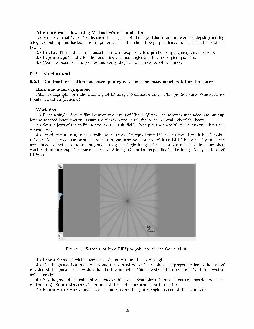
central axis).3.) Irradiate �lm using various collimator angles. An equidistant 15° spacing would result in 12 spokes
(Figure 13). The collimator star shot pattern can also be captured with an EPID imager. If your linearaccelerator cannot capture an integrated image, a single image of each strip can be acquired and thencombined into a composite image using the `2 Image Operation' capability in the Image Analysis Tools ofPIPSpro.
Figure 13: Screen shot from PIPSpro Software of star shot analysis.
4.) Repeat Steps 1-3 with a new piece of �lm, varying the couch angle.5.) For the gantry isocenter test, rotate the Virtual Water� such that it is perpendicular to the axis of
rotation of the gantry. Ensure that the �lm is centered at 100 cm SSD and centered relative to the centralaxis laterally.
6.) Set the jaws of the collimator to create thin �eld. Example: 0.4 cm x 20 cm (symmetric about thecentral axis). Ensure that the wide aspect of the �eld is perpendicular to the �lm.
7.) Repeat Step 3 with a new piece of �lm, varying the gantry angle instead of the collimator.
19
8.) Scan the �lms as gray-scale image with a resolution between 72 and 96 dpi. Save �les as a TIFF(.tif) or bitmap (.bmp).
9.) Open all the images in the PIPSpro Star Shot module and follow the analysis instructions as describedin the user's manual.
Note: a Winston-Lutz test (see 5.2.3) can also be used to verify the rotation isocenter.
5.2.2 Electron applicator interlocks
Recommended equipmentNone
Work �ow1.) If applicable, verify that the machine motion interlocks are activated when each applicator's touch
pad is pressed.2.) Verify that the machine beam interlocks are cleared when each applicator is correctly and fully
inserted into the accessory tray.
5.2.3 Coincidence of radiation and mechanical isocenter
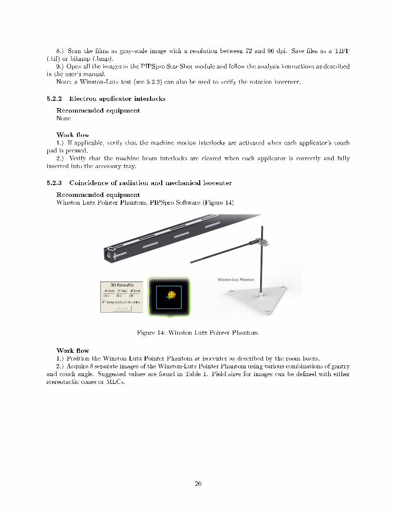
Recommended equipmentWinston-Lutz Pointer Phantom, PIPSpro Software (Figure 14)
Figure 14: Winston-Lutz Pointer Phantom.
Work �ow1.) Position the Winston-Lutz Pointer Phantom at isocenter as described by the room lasers.2.) Acquire 8 separate images of the Winston-Lutz Pointer Phantom using various combinations of gantry
and couch angle. Suggested values are found in Table 1. Field sizes for images can be de�ned with eitherstereotactic cones or MLCs.
20
Table 1: IAEA coordinate de�ned gantry and couch angle combinations for Winston-Lutz test.Gantry angle / 0 Couch angle / 0
60 0130 0230 0300 060 270130 270230 90300 90
3.) Open the stereotactic module in PIPSpro and follow the instructions for analysis as described in theuser's manual. The three-dimensional o�set calculated by the stereotactic module in PIPSpro describes thedi�erence between the Winston-Lutz ball marker and the radiation isocenter.
5.2.4 Tabletop sag
Recommended equipmentStack of Virtual Water� slabs or other heavy objects (weighing approximately 170 lbs or 77 kg)
Work �ow1.) Using the ODI or front pointer, set the treatment couch surface at 100 cm SSD.Extend the treatment
couch to the maximum longitudinal position towards the gantry.2.) Place the solid water at the head of the couch.3.) Verify that the displacement of the couch is within the expected tolerance.
5.2.5 Table angle
Recommended equipmentNone
Work �ow1.) Rotate the couch through the full range of angles and verify agreement between the digital and
mechanical readout at several angles.
5.3 MLC QA
5.3.1 MLC transmission
Recommended equipmentStandard Imaging MLC QA phantom, PIPSpro software, EPID imager
Work �ow1.) Set up the MLC QA phantom on the treatment couch at isocenter. Position the EPID imager at the
highest possible position without colliding with either the couch or the phantom to ensure that as many ofthe MLCs as possible can be acquired in an image.
2.) Set the MLCs such that they are closed at the isocenter plane, but are open slightly at the '0' positionand at a position 8 cm from center (3 cm if using a collimator that will not show the spherical marker at 8cm).
3.) Acquire an image and import it into PIPSpro. Follow the instructions for analysis as described inthe user's manual. (Figure 15)
21
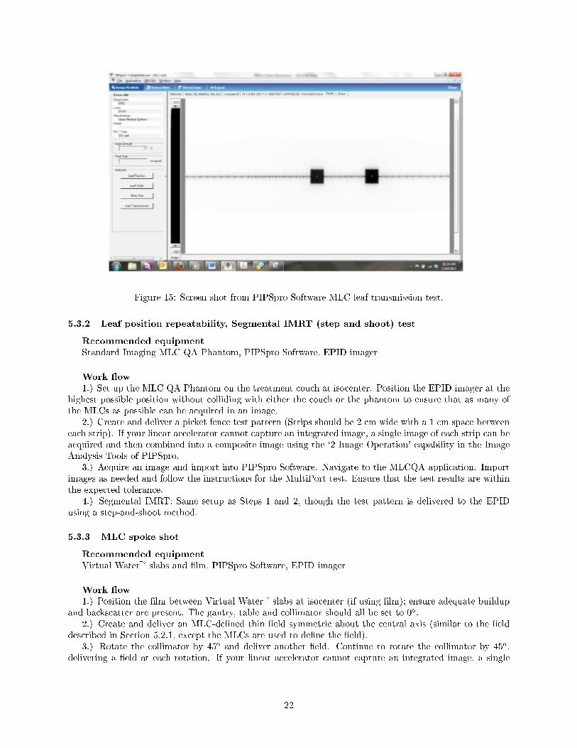
Figure 15: Screen shot from PIPSpro Software MLC leaf transmission test.
5.3.2 Leaf position repeatability, Segmental IMRT (step and shoot) test
Recommended equipmentStandard Imaging MLC QA Phantom, PIPSpro Software, EPID imager
Work �ow1.) Set up the MLC QA Phantom on the treatment couch at isocenter. Position the EPID imager at the
highest possible position without colliding with either the couch or the phantom to ensure that as many ofthe MLCs as possible can be acquired in an image.
2.) Create and deliver a picket fence test pattern (Strips should be 2 cm wide with a 1 cm space betweeneach strip). If your linear accelerator cannot capture an integrated image, a single image of each strip can beacquired and then combined into a composite image using the `2 Image Operation' capability in the ImageAnalysis Tools of PIPSpro.
3.) Acquire an image and import into PIPSpro Software. Navigate to the MLCQA application. Importimages as needed and follow the instructions for the MultiPort test. Ensure that the test results are withinthe expected tolerance.
4.) Segmental IMRT: Same setup as Steps 1 and 2, though the test pattern is delivered to the EPIDusing a step-and-shoot method.
5.3.3 MLC spoke shot
Recommended equipmentVirtual Water� slabs and �lm, PIPSpro Software, EPID imager
Work �ow1.) Position the �lm between Virtual Water� slabs at isocenter (if using �lm); ensure adequate buildup
and backscatter are present. The gantry, table and collimator should all be set to 0o.2.) Create and deliver an MLC-de�ned thin �eld symmetric about the central axis (similar to the �eld
described in Section 5.2.1, except the MLCs are used to de�ne the �eld).3.) Rotate the collimator by 45o and deliver another �eld. Continue to rotate the collimator by 45o,
delivering a �eld at each rotation. If your linear accelerator cannot capture an integrated image, a single
22
image of each strip can be acquired and then combined into a composite image using the `2 Image Operation'capability in the Image Analysis Tools of PIPSpro Software.
4.) If using �lm, scan the �lm as a gray-scale image using a resolution between 72 and 96 dpi. Save �lesas a TIFF (.tif) or bitmap (.bmp).
5.) Open the image in the main PIPSpro Software window and follow the star shot analysis instructionsas described in the user's manual.
5.3.4 Coincidence of light �eld and radiation �eld (all energies)
See Section 4.2.1.
5.4 Imaging QA
5.4.1 Planar MV imaging (EPID)
Full range of travel SDD
Recommended equipmentTape measure
Work �ow1.) With the gantry positioned at zero degrees, position the EPID at a preset distance (typically estab-
lished during commissioning).2.) Using the tape measure, measure the distance from the linac head to the top of the EPID. Verify
the measured distance is within the expected tolerance and repeat for two other known distances if desired.Note that the thickness of the front plate of the EPID may need to be taken into account on your system.
Imaging dose
Recommended equipmentExradin thimble ionization chamber, Virtual Water� phantom with chamber insert, MAX 4000 Elec-
trometer or SuperMAX Electrometer
Work �ow1.) Position the ionization chamber and phantom at a reference position.2.) Acquire a dose measurement using commonly used imaging parameters.3.) Compare measured values to baseline values and ensure they are within the expected tolerance.
5.4.2 Planar kV imaging
Beam quality/energy
Recommended equipmentExradin ionization chamber, MAX 4000 Electrometer or SuperMAX Electrometer, and high purity alu-
minum �lters
Work �ow1.) Perform a half-value layer (HVL) measurement and ensure the measured value is within the expected
tolerances relative to an established baseline.2.) Repeat for all clinically used kV values.
Imaging dose
23

Recommended equipmentExradin ionization chamber (diagnostic chamber), Max 4000 or SuperMAX Electrometer
Work �ow1.) Position the ionization chamber in air at a reference position. Note: the ionization chamber should
be calibrated for diagnostic beam energies.2.) Acquire an air-kerma measurement using commonly used imaging parameters.3.) Compare the measured value to the baseline value and verify it is within the expected tolerance.
5.4.3 Imaging dose: cone beam CT (kV and MV)
Recommended equipmentExradin farmer ionization chamber, cylindrical phantom with chamber insert(s)
Work �ow (kV CBCT)1.) Position the phantom and ionization chamber in a reference position. Note: the ionization chamber
should be calibrated for diagnostic beam energies.2.) Acquire a dose measurement in the center of the phantom and at the periphery if possible.3.) Compare the measured value(s) to the baseline value(s) and verify any discrepancies are within the
expected tolerance.Note: do not use a CT pencil chamber for cone beam imaging dose measurements. The
CBCT geometry is not the fan-beam geometry for which pencil chambers were designed, anduse of these chambers outside the intended geometry or beam quality range may lead tosigni�cant dose miscalculations.
Work �ow (MV CBCT)1.) Position the phantom and ionization chamber in a reference position.2.) Acquire a dose measurement in the center of the phantom, and at the periphery if possible.3.) Compare the measured value to the baseline value and verify it is within the expected tolerance.Note: do not use a CT pencil chamber for cone beam imaging dose measurements. The
CBCT geometry is not the fan-beam geometry for which pencil chambers were designed, anduse of these chambers outside the intended geometry or beam quality range may lead tosigni�cant dose miscalculations.
5.5 Wedge QA
5.5.1 Check of wedge angle for largest wedge, spot check for intermediate angle and �eld size
Recommended equipmentMatriXX�, Virtual Water� slabs
Work �ow1.) Setup the MatriXX� device as described in the user's manual.2.) Add enough Virtual Water� slabs such that the plane of measurement is at a depth of 10 cm.3.) Acquire a 60o dynamic wedge pro�le.4.) Verify that the o�-axis ratios within the central 80% of the �eld width are within the expected
tolerance relative to the baseline values.5.) Repeat Steps 3-4 for an intermediate angle and/or �eld size.
24

Trademarks
1.) Virtual Water� is a trademark of Med-Cal, Inc.2.) Varian® is a registered trademark of Varian Medical Systems, Inc.3.) CATPHAN® is a registered trademark of The Phantom Laboratory.4.) Iso-Align� is a trademark of Civco Medical Solutions5.) MatriXX� is a trademark of IBA Group6.) Elekta® is a registered trademark of Elekta AB
25