Embed Size (px)
Citation preview
User’s Guide Power Rail Booster V2.0 G34924-R2100-U2-A1 Date: 09/2003
Power Rail Booster User's Guide
Version V2.0 09/2003
Copyright Siemens AG 2003 All rights reserved. 6ES7 972-4AA01-0XA0 Page 1 of 41

User’s Guide Power Rail Booster V2.0 G34924-R2100-U2-A1 Date: 09/2003
Exclusion of liability We have checked the contents of this manual for agreement with the hardware and software described. Since deviations cannot be precluded entirely, we cannot guarantee full agreement. However, the data in this manual are reviewed regularly and any necessary corrections included in subsequent editions. Suggestions for improvement are welcomed.
Copyright Copyright Siemens AG 2003. All rights reserved The reproduction, transmission or use of this document or its contents is not permitted without express written authority. Offenders will be liable for damages. All rights, including rights created by patent grant or registration of a utility model or design, are reserved.
Copyright Siemens AG 2003 All rights reserved. 6ES7 972-4AA01-0XA0 Page 2 of 41
Technical specifications subject to change without prior notice.

User’s Guide Power Rail Booster V2.0 G34924-R2100-U2-A1 Date: 09/2003
Foreword Purpose of this manual This manual provides an overview of the Power Rail Booster for PROFIBUS DP and supports users in configuration, installation and commissioning. It is directed at persons, whose work involves the configuration, commissioning and/or servicing of automation systems.
Basic knowledge requirements General knowledge in the field of automation is required to use this manual. Validity The manual is designed for use with the Power Rail Booster for PROFIBUS DP with the Order No. 6ES7 972-4AA01-0XA0. Comparison with the previous version Each section in the previous version of the "Power Rail Booster for PROFIBUS DP" User's Guide was revised and supplemented to create this latest version.
Note: The previous version of this manual is recognizable by the number G34924-M2100-U2-A0 in the header line.
Copyright Siemens AG 2003 All rights reserved. 6ES7 972-4AA01-0XA0 Page 3 of 41
That number is now G34924-R2100-U2-A1.

User’s Guide Power Rail Booster V2.0 G34924-R2100-U2-A1 Date: 09/2003
C o n t e n t s
1 GENERAL REMARKS ..................................................................................................................... 6
2 INTRODUCTION............................................................................................................................... 8
2.1 APPLICATIONS.................................................................................................................................. 8 3 GENERAL FUNCTIONS................................................................................................................. 10
3.1 BASIC FUNCTION ............................................................................................................................ 10 3.2 MODE-INDEPENDENT FUNCTIONS .................................................................................................... 10 3.2.1 SUPPORTED PROTOCOLS............................................................................................................. 10 3.2.2 TRANSMISSION SPEED ................................................................................................................. 10 3.2.3 SIGNAL REGENERATION ............................................................................................................... 11 3.2.4 SHORT-CIRCUIT DETECTION ......................................................................................................... 11 3.2.5 MONITORING OF THE OUTPUT TEMPERATURE ................................................................................ 11 3.2.6 COMMISSIONING AIDS .................................................................................................................. 11 4 NETWORK TOPOLOGIES FOR CONTACT RAIL SYSTEMS...................................................... 12
4.1 TERM DEFINITIONS.......................................................................................................................... 12 4.2 INTRODUCTION ............................................................................................................................... 13 4.3 EXAMPLES OF TOPOLOGIES............................................................................................................. 13 4.3.1 CASCADING................................................................................................................................. 13 4.3.2 POINT-TO-POINT CONNECTION ..................................................................................................... 13 4.3.3 LINE TOPOLOGY .......................................................................................................................... 14 4.3.4 STAR TOPOLOGY ......................................................................................................................... 14 4.3.5 CLOSED RING CIRCUITS ............................................................................................................... 15 4.4 RAIL SECTIONS............................................................................................................................... 16 5 CONFIGURATION.......................................................................................................................... 17
5.1 PROCEDURE .................................................................................................................................. 17 5.2 CONFIGURATION WITH THE "PRB CHECKER" ................................................................................... 19 5.3 CONFIGURATION OF THE BUS PARAMETERS...................................................................................... 20 5.4 CONFIGURING THE CONTACT RAILS AND SLIDING CONTACTS.............................................................. 21 5.4.1 INTRODUCTION ............................................................................................................................ 21 5.4.2 CONTACT RAIL CAPACITANCE ....................................................................................................... 22 5.4.3 CONTACT RESISTANCE BETWEEN CONTACT RAILS AND SLIDING CONTACTS ..................................... 22 6 COMMISSIONING .......................................................................................................................... 23
6.1 SAFETY INFORMATION..................................................................................................................... 23 6.2 GENERAL INFORMATION REGARDING COMMISSIONING....................................................................... 24 6.3 INSTALLATION................................................................................................................................. 25 6.3.1 INSTALLING A PRB ...................................................................................................................... 25 6.3.2 INTERFACES AND CONNECTOR PIN ASSIGNMENT............................................................................ 26 6.3.2.1 Graphical interface diagram, galvanic isolation ..................................................................... 26 6.3.2.2 Wiring guidelines for interfaces.............................................................................................. 26 6.3.2.3 Connecting the Power Rail interface...................................................................................... 27 6.3.2.4 Connecting the PROFIBUS interface..................................................................................... 27 6.3.2.5 Connecting the operating voltage .......................................................................................... 28 6.3.2.6 Connecting the signalling contacts ........................................................................................ 28 6.3.2.7 Connection scheme for wiring PRB ....................................................................................... 28 6.4 DETERMINING THE TRANSFER RESISTANCE OF COLLECTORS ............................................................. 29
Copyright Siemens AG 2003 All rights reserved. 6ES7 972-4AA01-0XA0 Page 4 of 41
6.4.1.1 Measuring individual resistances ........................................................................................... 29

User’s Guide Power Rail Booster V2.0 G34924-R2100-U2-A1 Date: 09/2003
6.4.1.2 Measuring the series resistances on individual double sliding contacts................................ 29 6.4.1.3 Measuring the serial resistances on both double sliding contacts......................................... 29 7 LED DISPLAY AND TROUBLESHOOTING.................................................................................. 30
7.1 DIAGNOSTIC DISPLAYS FOR THE POWER RAIL BOOSTER................................................................... 30 7.2 FAULT SCENARIOS IN A DP MASTER SYSTEM WITH PRBS ................................................................. 31 8 TECHNICAL SPECIFICATIONS .................................................................................................... 32
9 APPENDIX...................................................................................................................................... 34
9.1 EXAMPLES FOR APPLICATIONS ........................................................................................................ 34 9.1.1 BLOCK SEQUENCE CONTROL ........................................................................................................ 34 9.2 CE LABEL ...................................................................................................................................... 35 9.3 GLOSSARY..................................................................................................................................... 36 10 LIST OF FIGURES ....................................................................................................................... 40
Copyright Siemens AG 2003 All rights reserved. 6ES7 972-4AA01-0XA0 Page 5 of 41
User’s Guide Power Rail Booster V2.0 G34924-R2100-U2-A1 Date: 09/2003
1 General remarks
Safety-related
remarks
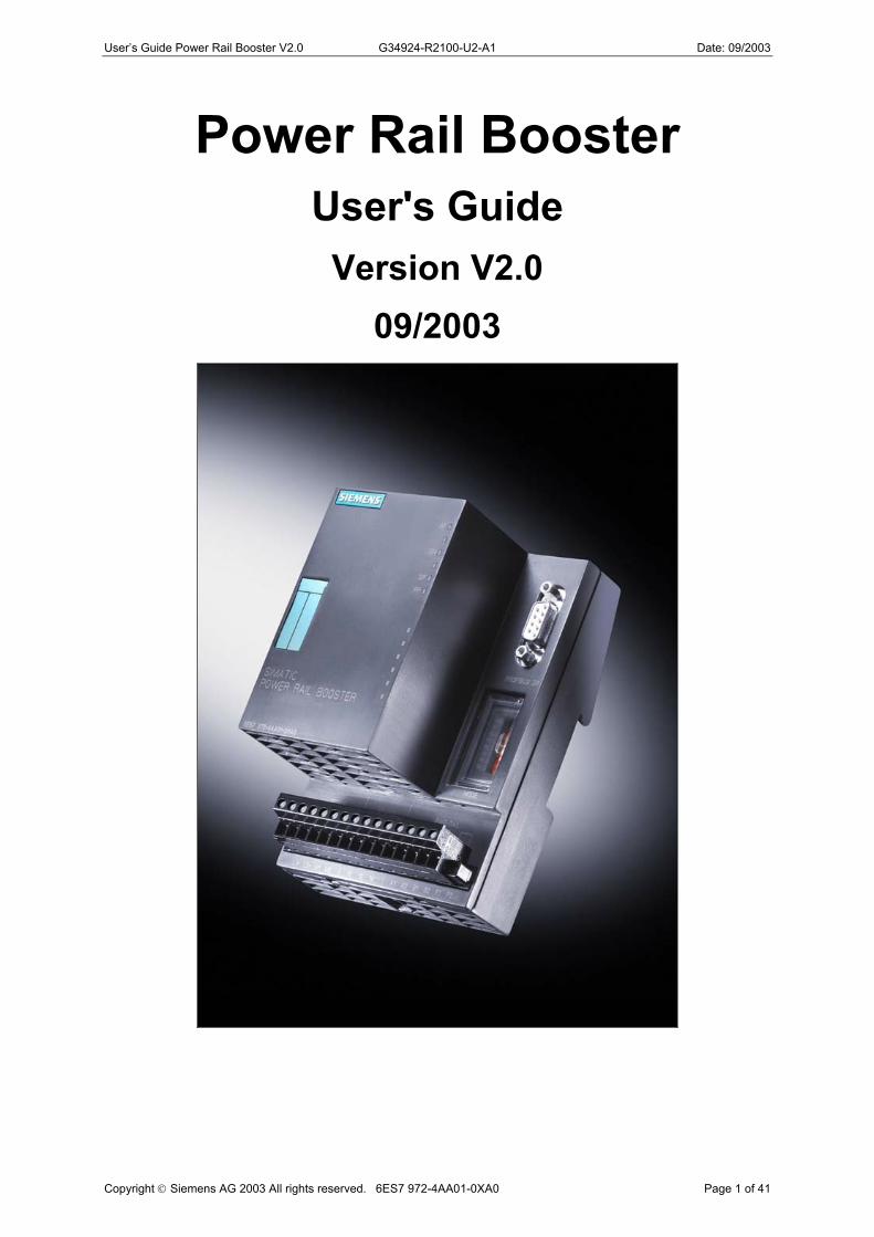
This User's Guide contains warnings that you must observe for your own personal safety as well as to avoid material damage. The warnings are emphasized by a warning triangle and appear as follows in dependence on the danger level:
U Danger This means that death, serious injury or substantial material damage will occur if the prescribed precautionary measures are not taken.
U Warning This means that death, serious injury or substantial materialdamage may occur if the prescribed precautionary measures are not taken.
U Caution This means that minor injuries or light material damage may occur if the prescribed precautionary measures are not taken.
Copyright Siemens AG 2003 All rights reserved. 6ES7 972-4AA01-0XA0 Page 6 of 41
Note Provides important information about the product, the handling of the product or about a specific part of the documentation to which attention needs to be called.
User’s Guide Power Rail Booster V2.0 G34924-R2100-U2-A1 Date: 09/2003
Qualified personnel
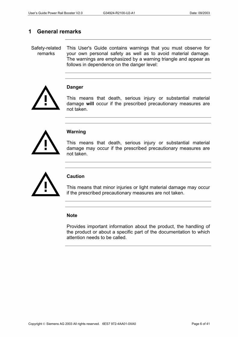
A device may be put into operation or operated only by qualified personnel. For the purposes of this manual, qualified personnel are persons who are authorized to put into operation, ground and designate devices, systems and electrical circuits.
Control cabinet
For the purposes of this User's Guide, a control cabinet must fulfil the fire enclosure requirements to EN 60950.
U
Warning The device is intended for operation in control cabinets or closed equipment rooms. The device may not be opened.
U
Warning The configuring engineer is always responsible for ensuring that data transmission errors cannot produce a dangerous situation.
Copyright Siemens AG 2003 All rights reserved. 6ES7 972-4AA01-0XA0 Page 7 of 41
Use as
prescribed
The device may be used only for the applications described in this Guide and only in conjunction with non-Siemens devices and components recommended or authorized by Siemens. Proper transport, storage and installation as well as careful operation and maintenance of the device are prerequisites for problem-free and safe operation.

User’s Guide Power Rail Booster V2.0 G34924-R2100-U2-A1 Date: 09/2003
2 Introduction
The PRB (Power Rail Booster) is intended for use as a network component in electrical PROFIBUS networks. It's purpose is the amplification and safe, reliable transmission of PROFIBUS signals. The PRB enables the transmission of PROFIBUS signals over contact rails, loops and other cable types (such as telephone cables) not compliant with the PROFIBUS Specification. The PRB also enables data transmission in the face of an excessive EMC load.
The PRB can be easily integrated in existing PROFIBUS fieldbus networks. It is also possible to configure a complete PROFIBUS fieldbus network in line and/or star topology. Except for the Power Booster itself, no other filters or terminating elements are required for safe, reliable data transmission.
Every PRB has two independent, isolated interfaces, each in turn consisting of a transmitter component and a receiver component.
The primary channel is designed as 9-pin D subminiature (female) socket connector. An RS 485 bus segment to PROFIBUS Standard EN 50170 can be connected to this channel.
The secondary channel is run to a terminal strip. There are two pins for each signal (A1, A2 and B1, B2). A power rail segment can be connected to this channel. The nominal cross-sectional area measures 2.5mm².
7 LEDs signal the current status as well as any malfunctions.
The operating voltage supply comes from 24 V direct voltage.
At least two Power Rail Boosters are required for a transmission link.
2.1 Applications
Primary applications for the Power Rail Booster include:
- Motor-driven overhead trolley conveyors, - Storage/retrieval devices, - Crane installations, - Rotary feed through units and rotary tables, - Lifts and hoisting apparatus, - Traversing tracks
Copyright Siemens AG 2003 All rights reserved. 6ES7 972-4AA01-0XA0 Page 8 of 41
It is also generally recommended that the Power Booster be used for cost-efficient, safe and reliable PROFIBUS transmissions via contact rails or cables.
User’s Guide Power Rail Booster V2.0 G34924-R2100-U2-A1 Date: 09/2003
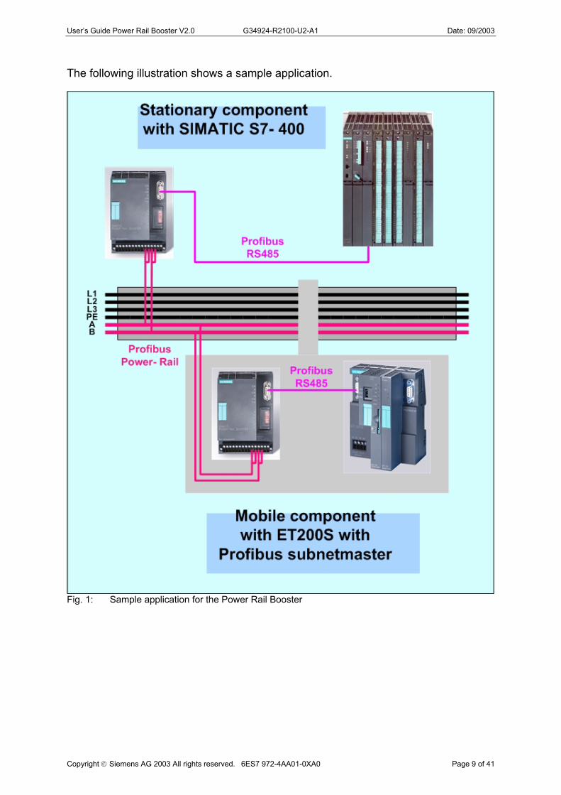
The following illustration shows a sample application.
Copyright Siemens AG 2003 All rights reserved. 6ES7 972-4AA01-0XA0 Page 9 of 41
Fig. 1: Sample application for the Power Rail Booster
User’s Guide Power Rail Booster V2.0 G34924-R2100-U2-A1 Date: 09/2003
3 General functions
3.1 Basic function
The basic functionality of the Power Rail Booster is safe, reliable, bidirectional data transmission. Following power-up, the PRB begins an automatic search for the baud rate. Data transmission is activated as soon as a valid baud rate is found. If the master then sends a request to its slave, data coming in over the RS485 interface are received by the stationary PRB, elevated to a noise-free level, and sent to the moving PRB on the power rail side, which receives the data, converts them to the RS485 level and sends them to the slave. The slave's response to the master is transferred in the same manner, but in reverse order.
3.2 Mode-independent functions
Mode-independent functions are functions which are permanently executed or supported by the Power Rail Booster.
3.2.1 Supported protocols The PRB is designed for use as a network component in electrical PROFIBUS networks. It is a pure transformer, and is largely transparent as PROFIBUS device. It has no PROFIBUS address. Messages are checked for syntax, but the data are not checked for correctness as regards their content. The Power Rail Booster supports mono- and multi-master systems. PROFIBUS DP/FMS, as well as FDL and MPI, are transferred as protocols.
U
Warning If there are active stations on both sides of the power rail section, all stations are at risk of a brief failure in the wake of line interruptions.
3.2.2 Transmission speed
The Power Rail Booster supports the following EN 50170-compliant transmission speeds (baud rates): 9.6 kBit/s, 19.2 kBit/s, 45.45 kBit/s, 93.75 kBit/s, 187.5 kBit/s and 500 kBit/s
Copyright Siemens AG 2003 All rights reserved. 6ES7 972-4AA01-0XA0 Page 10 of 41
The transmission speed is set automatically as soon as the Power Rail Booster receives valid messages over an interface. If the transmission speed is not yet known, the outputs for all interfaces are disabled. The PRBs recognize any changes in the transmission speed during operation and reconfigure themselves accordingly. Brief transmission problems may occur at the moment of switch-over.
User’s Guide Power Rail Booster V2.0 G34924-R2100-U2-A1 Date: 09/2003
3.2.3 Signal regeneration The PRB regenerates the signal waveshape of the data received, making it possible to cascade as many as 10 PRBs. The signal throughput time is 6 tbits per PRB.
3.2.4 Short-circuit detection
The two interfaces on the PRB are monitored for short circuits. If a short circuit is detected, the transmitter components are shut down. When the problem has been rectified, they are automatically put back into operation as described in Section 3.1, "Basic function". Critical states are signalled as described in Section 7, "LED display and troubleshooting".
3.2.5 Monitoring of the output temperature
The output element is protected against overload by a temperature monitor. The monitor shuts the output element down when a critical temperature is exceeded. When the output has cooled down, the PRB automatically restarts data transmission. Critical states are signalled as described in Chapter 7, "LED display and troubleshooting".
3.2.6 Commissioning aids
Copyright Siemens AG 2003 All rights reserved. 6ES7 972-4AA01-0XA0 Page 11 of 41
At least one active station is required to test the Power Rail connection during installation. That station is usually the PROFIBUS master on the stationary side of the Power Rail. This station serves as message source. On power-up, the Power Rail Boosters are passive. They recognize the transmission speed based on the messages sent by the station. The diagnostic LEDs on the front of the Power Rail Booster provide a visual aid.

User’s Guide Power Rail Booster V2.0 G34924-R2100-U2-A1 Date: 09/2003
4 Network topologies for contact rail systems
4.1 Term definitions
Contact rail system Communication between stationary plant control system and mobile vehicles takes place over PROFIBUS DP. Signals from the master are amplified by the PRB and fed into the contact rails. The vehicle picks off the amplified signals with the collector. The moving PRB then transforms the signals back to the Standard PROFIBUS signal level. DP master segment A contact rail system can be connected to the PROFIBUS via one or more than one PROFIBUS master. The segment of a contact rail system in which data interchange takes place via a PROFIBUS master is referred to as a "DP master segment". Normally, a contact rail system consists of only one DP master segment. If there are multiple DP master segments, care must be taken to see that no electrical connection (short circuit) can be established between DP master segments via the double collector. This can be done using rail sections (see Section 4.4). PRB segment As a rule, more than one stationary Power Rail Booster is required to supply a contact rail system with PROFIBUS signals. The subsegment of a contact rail system in which data interchange takes place via a PRB is referred to as "PRB segment". A PRB segment is thus a subsegment of a DP master segment. It must be ensured that no electrical connection (short circuit) can be established between two PRB segments via the double collector. This can be done using rail sections (see Section 4.4).
Copyright Siemens AG 2003 All rights reserved. 6ES7 972-4AA01-0XA0 Page 12 of 41
Fig. 2: Block diagram of a DP master segment with two PRB segments

User’s Guide Power Rail Booster V2.0 G34924-R2100-U2-A1 Date: 09/2003
4.2 Introduction
The following network topologies can be implemented using the Power Rail Booster:
- Cascading of Power Rail sections, - Point-to-point connections, - Line topology - Star topology (contact rail system) - Closed loop
Combinations of the above are also possible. Two contact rails or cable strands are used to set up the Power-Rail sections for these network topologies. All cabling or wiring for the contact rails must be done with PROFIBUS cable.
4.3 Examples of topologies
4.3.1 Cascading
The PRB regenerates the signal waveshape of the data received, making it possible to cascade as many as 10 PRBs.
Fig. 3: Example of cascading
4.3.2 Point-to-point connection
This configuration is distinguished by the fact that only one PRB is installed on each side of the Power Rail section.
Copyright Siemens AG 2003 All rights reserved. 6ES7 972-4AA01-0XA0 Page 13 of 41
Fig. 4: Example of a point-to-point connection

User’s Guide Power Rail Booster V2.0 G34924-R2100-U2-A1 Date: 09/2003
4.3.3 Line topology
This configuration is distinguished by the fact that multiple contact rail segments are cabled as one line and multiple PRBs are installed on the moving side.
Fig. 5: Example of line topology
4.3.4 Star topology
This configuration is distinguished by the fact that multiple contact rail segments are cabled in a star structure and that more than one PRB is installed on the moving side. The star structure is permissible on no more than two levels (paths and branches).
Copyright Siemens AG 2003 All rights reserved. 6ES7 972-4AA01-0XA0 Page 14 of 41
Fig. 6: Example of star topology

User’s Guide Power Rail Booster V2.0 G34924-R2100-U2-A1 Date: 09/2003
4.3.5 Closed ring circuits
When using systems with closed loops, it is recommended to establish a low-resistance connection to ground with the steel construction parallel to the contact rail.
Copyright Siemens AG 2003 All rights reserved. 6ES7 972-4AA01-0XA0 Page 15 of 41
Fig. 7: Example of a closed loop

User’s Guide Power Rail Booster V2.0 G34924-R2100-U2-A1 Date: 09/2003
4.4 Rail sections
Two types of rail section (Figs. 8 and 9) can be used. A double rail section can maintain communication even during a segment change through suitable switching of the PRB segments using contactors/relays.
Fig. 8: Example of a double rail section
The isolating rail section is the cost-optimized solution for a segment change.
Fig. 9: Example of an isolating rail section
Here, the contact rails in the two segments are separated by a non-conductive section.
The isolating rail section can be created by isolating the contact rail with a suitable isolator. In addition to isolating properties, it is also necessary to take mechanical properties, particularly those relating to abrasion, into account.
Another way of creating an isolating rail section is to use an isolator instead of a conductor as contact rail.
Copyright Siemens AG 2003 All rights reserved. 6ES7 972-4AA01-0XA0 Page 16 of 41
U
Note When installing rail sections, care must be taken when aligning the junctions in order to avoid bounce.

User’s Guide Power Rail Booster V2.0 G34924-R2100-U2-A1 Date: 09/2003
5 Configuration
5.1 Procedure
Configuration is handled in steps with the aid of the "PRB Checker" tool and application-specific data as described below.
1. Checking to see whether there is a need for dividing the layout into multiple DP master segments.
Prerequisites: - Knowledge of the total number of vehicles in the plant - Knowledge of the maximum permissible typical bus cycle time for the
application
Division of the layout is always required when: - there are more than 125 vehicles in the plant
or - shorter typical bus cycle times are required
or - the base load of the infeed PRB is to be reduced
Result: - Number of DP master segments - Transmission speed used.
2. Checking to see whether there is a need to divide the number of DP master segments specified in Step 1 into multiple PRB segments. This step must be performed separately for each DP master segment specified in Step 1.
Prerequisites: - Results from Step 1 - "PRB Checker" configuring tool - Layout of the plant with dimensions - Number of slaves in the relevant DP master segment - Number of vehicles in the relevant PRB segment - Length of the cable between collector and vehicle - Maximum length of the data in the input/output bytes to be interchanged
between stationary control system and vehicle control system
Division is always required when it is not possible - to supply the entire rail length of the relevant DP master segment
or - to supply the maximum possible number of vehicles in the relevant DP
master segment
Copyright Siemens AG 2003 All rights reserved. 6ES7 972-4AA01-0XA0 Page 17 of 41
User’s Guide Power Rail Booster V2.0 G34924-R2100-U2-A1 Date: 09/2003
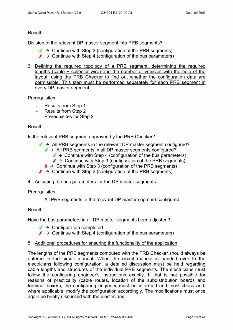
Result:
Division of the relevant DP master segment into PRB segments? Continue with Step 3 (configuration of the PRB segments) Continue with Step 4 (configuration of the bus parameters)
3. Defining the required topology of a PRB segment, determining the required lengths (cable + collector wire) and the number of vehicles with the help of the layout, using the PRB Checker to find out whether the configuration data are permissible. This step must be performed separately for each PRB segment in every DP master segment.
Prerequisites: - Results from Step 1 - Results from Step 2 - Prerequisites for Step 2
Result:
Is the relevant PRB segment approved by the PRB Checker? All PRB segments in the relevant DP master segment configured?
All PRB segments in all DP master segments configured? Continue with Step 4 (configuration of the bus parameters) Continue with Step 3 (configuration of the PRB segments)
Continue with Step 3 (configuration of the PRB segments) Continue with Step 3 (configuration of the PRB segments)
4. Adjusting the bus parameters for the DP master segments.
Prerequisites: - All PRB segments in the relevant DP master segment configured
Result:
Have the bus parameters in all DP master segments been adjusted? Configuration completed Continue with Step 4 (configuration of the bus parameters)
5. Additional procedures for ensuring the functionality of the application
Copyright Siemens AG 2003 All rights reserved. 6ES7 972-4AA01-0XA0 Page 18 of 41
The lengths of the PRB segments computed with the PRB Checker should always be entered in the circuit manual. When the circuit manual is handed over to the electricians following configuration, a detailed discussion must be held regarding cable lengths and structures of the individual PRB segments. The electricians must follow the configuring engineer's instructions exactly. If that is not possible for reasons of practicality (cable routes, location of the subdistribution boards and terminal boxes), the configuring engineer must be informed and must check and, where applicable, modify the configuration accordingly. The modifications must once again be briefly discussed with the electricians.
User’s Guide Power Rail Booster V2.0 G34924-R2100-U2-A1 Date: 09/2003
5.2 Configuration with the "PRB Checker"
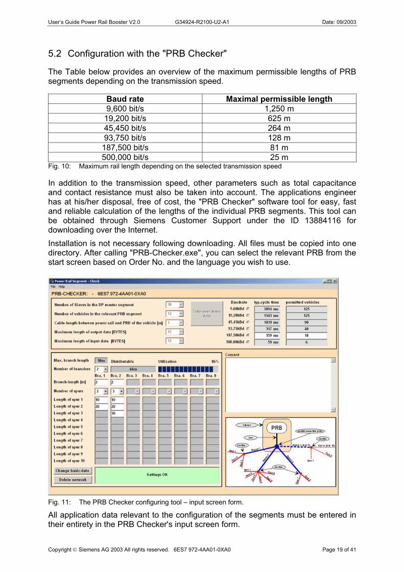
The Table below provides an overview of the maximum permissible lengths of PRB segments depending on the transmission speed.
Baud rate Maximal permissible length 9,600 bit/s 1,250 m
19,200 bit/s 625 m 45,450 bit/s 264 m 93,750 bit/s 128 m
187,500 bit/s 81 m 500,000 bit/s 25 m
Fig. 10: Maximum rail length depending on the selected transmission speed
In addition to the transmission speed, other parameters such as total capacitance and contact resistance must also be taken into account. The applications engineer has at his/her disposal, free of cost, the "PRB Checker" software tool for easy, fast and reliable calculation of the lengths of the individual PRB segments. This tool can be obtained through Siemens Customer Support under the ID 13884116 for downloading over the Internet. Installation is not necessary following downloading. All files must be copied into one directory. After calling "PRB-Checker.exe", you can select the relevant PRB from the start screen based on Order No. and the language you wish to use.
Fig. 11: The PRB Checker configuring tool – input screen form.
Copyright Siemens AG 2003 All rights reserved. 6ES7 972-4AA01-0XA0 Page 19 of 41
All application data relevant to the configuration of the segments must be entered in their entirety in the PRB Checker's input screen form.

User’s Guide Power Rail Booster V2.0 G34924-R2100-U2-A1 Date: 09/2003
The program checks the input data immediately after each modification. If the result for the data entered is positive (green field), the relevant segment may be regarded as operational. If the result is negative (red field), there are two possibilities:
- the permissible line length (reflection limit) has been exceeded or
- the permissible load (capacitance) has been exceeded. If the permissible line length has been exceeded, you must reduce the length of the PRB segment until the Checker gives you the green light for your configuration. If the load has been exceeded, you can reduce the length of the line, the number of vehicles in the PRB segment or the number of vehicles in the DP master segment. In this way, you configure segment by segment as described in Section 5.1, "Procedure", until you have structured the entire length of your contact rail, including cabling, in the DP master and PRB segments. You can also add comments and store your configuration segment by segment. The files can then be sent by e-mail and downloaded at another location. In the past, this has proven very successful as installation, documentation and quality control support.
5.3 Configuration of the bus parameters
Because of the way the PRB functions (see Section 3.2.3), the network parameters for the DP master segment must be configured depending on topology. This is done using Hardwareconfig in STEP-7 or COM PROFIBUS in STEP-5.
Copyright Siemens AG 2003 All rights reserved. 6ES7 972-4AA01-0XA0 Page 20 of 41
Fig. 12: Configuring the network parameters in Step 7's Hardware Configuration

User’s Guide Power Rail Booster V2.0 G34924-R2100-U2-A1 Date: 09/2003
In the screen form shown above, the number of OLMs (Optical Link Modules) must be entered on the "Fiber Optics" line. The following applies:
- One OLM is equivalent to one PRB - The line length remains unchanged
The configuration tools then check to see whether the Slot Time parameter in the selected communications profile can be left unchanged. If the slot time were to be exceeded due to additional delays caused by Power Rail Boosters, a warning message is issued and the parameters modified accordingly.
The number of OLMs to be entered as the equivalent of the existing PRBs depends on topology and delay level.
The minimum number of OLMs to be configured when using PRBs is 2.
The following computational rule is applied to cascade configurations:
Number of OLMs = Number of PRBs connected in series The delay level is: Tv (in Tbit) = 2 *Number of OLMs * 6Tbit
Note In DP master systems in which parameters are not assigned using STEP7 resp. COM PROFIBUS, the slot time must be computed and the bus parameters corrected using the DP master configuring tool. The procedure involved must be taken from the configuring tool manufacturer's documentation.
U
Warning Failure to adjust the slot time by configuring a value that is too low may result in communication problems.
5.4 Configuring the contact rails and sliding contacts
5.4.1 Introduction
Copyright Siemens AG 2003 All rights reserved. 6ES7 972-4AA01-0XA0 Page 21 of 41
The PRB enables PROFIBUS transmission over contact rails. Other than the limit values for capacitance and contact resistance, the PRB makes no special demands on the contact rail systems. Double collectors must be used in order to ensure continuous contact. The maintenance instructions provided by the contact rail supplier must be observed to ensure long-term compliance with the limit values.

User’s Guide Power Rail Booster V2.0 G34924-R2100-U2-A1 Date: 09/2003
5.4.2 Contact rail capacitance
The higher the capacitance of the contact rails, the lower the distributable rail length per Power Booster segment. The "PRB Checker" configuration tool's internal calculations are based on a rail capacitance of 45nF/km. Contact rails with a higher capacitance per unit length should not be used.
5.4.3 Contact resistance between contact rails and sliding contacts
Another important parameter value to which the contact rail systems must conform is the contact resistance between contact rails and sliding contacts. In order to ensure reliable data transmission, this value must not exceed a value of 100 ohms per sliding contact.
Depending on the obtaining ambient conditions, contamination and oxidation of the contact rails, particularly those made of copper (alloys), must always be reckoned with in all contact rail systems, although the constant travel of sliding contacts over a contact rail does have a certain self-cleaning effect. Particular attention must be paid to maintenance on those sections over which there is little travel, such as servicing areas, sidings, out-of-the-way areas and so on.
It is therefore of the utmost importance that maintenance and cleaning be sufficiently frequent so as not to endanger problem-free data transmission through contaminated or oxidized contact rails, sliding contacts or switching contacts.
U
Warning When the application in question requires the Power Rail signal to pass through switching elements (contactors, switches, etc.), special care must be taken to ensure that the contact resistance of these elements' contacts does not exceed a value of 100 ohms, even in instances of little use, such as maintenance switches in servicing areas, as failure to do so could result in data transmission errors!
Copyright Siemens AG 2003 All rights reserved. 6ES7 972-4AA01-0XA0 Page 22 of 41
U
Note To ensure reliable, safe data transmission, the use of mechanically independent double sliding contacts is mandatory. These sliding contacts must be installed and set so that there is adequate surface pressure between sliding contacts and contact rails at all times. Too little pressure and poorly adjusted contact rail junctions result in bounce and thus lead to interruptions in data transmission.

User’s Guide Power Rail Booster V2.0 G34924-R2100-U2-A1 Date: 09/2003
6 Commissioning
6.1 Safety information
U
Use PRBs only as described in this User's Guide. Pay particular attention to all warnings and safety-related information.
U
Operate a PRB only with a safety extra-low voltage to IEC 950/EN 60 950/VDE 0805 of no more than +32 V (+24 V typical). In accordance with UL/CSA, the voltage source must be NEC Class 2-compliant.
U
Observe the electrical limit values when connecting voltage to the signalling contacts: 250 V AC / 30 V DC, rated operating current: 2A, rated output power: 62.5 VA / 60W. These data also apply to resistive loads.
U
Danger Never connect the Power Rail Booster to mains voltage.
U
Select a location for installation which full fills the ambient conditions and mechanical limit values shown in the technical specifications.
U
Take steps to ensure that an installation error such as a wire break cannot result in undefined states within the plant.
Copyright Siemens AG 2003 All rights reserved. 6ES7 972-4AA01-0XA0 Page 23 of 41
U
Take the necessary measures and/or install suitable elements to ensure that all interfaces are protected against lightning strikes affecting the plant, whether indoors or outdoors.

User’s Guide Power Rail Booster V2.0 G34924-R2100-U2-A1 Date: 09/2003
6.2 General information regarding commissioning
When configuration has been completed, the following steps must be taken to put the PRB into operation:
Set all DIL switches to the OFF position Install the PRB Connect the supply voltage and signalling contacts Connect the Power Rail Connect the RS485 bus cable with preassembled bus connector
Fig. 13: Front view of the Power Rail Booster. Location of the DIL switches and of the terminal block for the . operating voltage, group fault relay and Power Rail connection.
Copyright Siemens AG 2003 All rights reserved. 6ES7 972-4AA01-0XA0 Page 24 of 41

User’s Guide Power Rail Booster V2.0 G34924-R2100-U2-A1 Date: 09/2003
6.3 Installation
6.3.1 Installing a PRB
A PRB can be mounted on a DIN EN 50022-compliant standard mounting rail with the dimensions 35x15mm or 7.5x15mm. A PRB must be installed or removed only when the supply voltage is switched off.
The PRB must be installed horizontally on a vertical wall as shown in Fig. 14. The location must be selected to suit the ambient conditions and mechanical
limit values shown in the technical specifications. Sufficient space to connect all lines and cables must be available at the chosen
location. In order to ensure sufficient heat dissipation, a space of at least 15mm must separate the upper corner of the PRB from the housing.
Install the PRB only on a low-resistance and low reactance-grounded mounting rail or mounting plate.
Installing a PRB on/removing a PRB from a mounting rail
Insert the upper locking hook on the PRB into the DIN rail and press the bottom surface, as shown in Fig.14, against the rail until the PRB clicks into place. The PRB is removed by pulling the locking lever downward. With the lever held
down, the PRB can be simply lifted off the mounting rail.
Copyright Siemens AG 2003 All rights reserved. 6ES7 972-4AA01-0XA0 Page 25 of 41
Fig. 14: Installing a PRB on a standard mounting rail
User’s Guide Power Rail Booster V2.0 G34924-R2100-U2-A1 Date: 09/2003
6.3.2 Interfaces and connector pin assignment
6.3.2.1 Graphical interface diagram, galvanic isolation
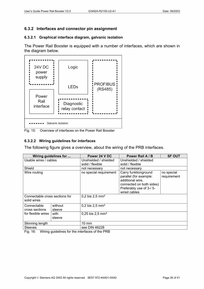
The Power Rail Booster is equipped with a number of interfaces, which are shown in the diagram below.
Fig. 15: Overview of interfaces on the Power Rail Booster
6.3.2.2 Wiring guidelines for interfaces
The following figure gives a overview, about the wiring of the PRB interfaces.
Wiring guidelines for ... Power 24 V DC Power Rail A / B SF OUT Usable wires / cables Unshielded / shielded
solid / flexible Unshielded / shielded solid / flexible
Shield not necessary not necessary Wire routing no special requirement Carry funktionground
parallel (for example: additional wire, connected on both sides) Preferably use of 3-/ 5- wired cables
no special requirement
Connectable cross sections for solid wires
0,2 bis 2,5 mm²
without sleeve
0,2 bis 2,5 mm² Connectable cross sections for flexible wires with
sleeve 0,25 bis 2,5 mm²
Skinning length 10 mm Sleeves see DIN 46228
Copyright Siemens AG 2003 All rights reserved. 6ES7 972-4AA01-0XA0 Page 26 of 41
Fig. 16: Wiring guidelines for the interfaces of the PRB

User’s Guide Power Rail Booster V2.0 G34924-R2100-U2-A1 Date: 09/2003
6.3.2.3 Connecting the Power Rail interface
The connection is established via the 15-pin terminal block on the front of the PRB.
Because of their low capacitance, all cables to the contact rail on the Power Rail side, such as incoming cables and connecting cables, should be PROFIBUS cables. In principle, however, it is also possible to use other cable types, in which case the maximum cable length must match the cable capacitance.
Outputs A1/A2 as well as B1/B2 must be jumpered. This can be implemented by individually feeding the sliding contacts from the double collector or via an external jumper.
Pin No. Name Function 10 A1 Contact rail A, first sliding contact 11 A2 Contact rail A, second sliding contact 12 B1 Contact rail B, first sliding contact 13 B2 Contact rail B, second sliding contact 14 ε Functional ground 15 ε Functional ground
Fig. 17: Terminal assignment for the Power Rail interface
6.3.2.4 Connecting the PROFIBUS interface
PRBs are equipped with an electrical port with RS 485 level. This port takes the form of a 9-pin D Subminiature socket with screw-type locking mechanism. Bus lines A and B are galvanically isolated from the 24 V supply voltage and the Power Rail voltage. The port is located on the front of the PRB.
For the PROFIBUS DP side, the installation guidelines contained in the "SIMATIC NET PROFIBUS Networks" manual apply.
Connect the RS 485 bus segment using a PROFIBUS bus connector. If the PRB is located at the beginning or end of a bus segment, the bus terminator on this interface must be switched on.
All PROFIBUS bus connectors in the network must be screwed tightly into the RS 485 interface.
Make sure that the bus segment connected to the RS485 interface is terminated at both ends.
Pin No. Name Function 1 n.c. Reserved 2 n.c. Reserved 3 RxD/TxD-P Data line B 4 RTS Request to Send 5 GND Ground 6 VCC Supply voltage 7 n.c. Reserved 8 RxD/TxD-N Data line A 9 n.c. Reserved
Copyright Siemens AG 2003 All rights reserved. 6ES7 972-4AA01-0XA0 Page 27 of 41
Fig. 18: Terminal assignment for the PROFIBUS RS485 interface

User’s Guide Power Rail Booster V2.0 G34924-R2100-U2-A1 Date: 09/2003
6.3.2.5 Connecting the operating voltage
The operating voltage is connected via the 15-pin terminal block on the front of the PRB. The connection is protected against polarity reversal. Pins 1-2 and pins 3-4 are jumpered internally. Supply the PRB only with safety extra-low voltage to IEC 60634-4-41
"Generation as Functional Extra-low Voltage with Safe Electrical Isolation", 20.4 V DC 20 to 28.8 V DC (+24 V typical).
The PRB must be operated with a grounded incoming supply. The reference potential (ground) of the 24 V DC supply voltage must be connected to PE.
Be sure there is sufficient tensile load and observe the cable's minimum bending radii.
Pin No. Name Function 1 L1+ 24 V DC 2 L2+ 24 V DC 3 M1 Ground 4 M2 Ground Fig. 19: Terminal assignment for the supply voltage interface
6.3.2.6 Connecting the signalling contacts
A relay with potential-free contacts is provided for signalling faults or the failure of the operating voltage. The signalling contact can be connected to a controller's digital I/O via the 15-pin terminal block on the front of the PRB.
Be sure there is a sufficient tensile load and observe the cable's minimum bending radii.
Pin No. Name Function 6 11 Shared connector pin 7 12 NC contact, opens in the event of a group fault or missing VCC 8 14 NO contact, closes in the event of a group fault or missing VCC Fig. 20: Terminal assignment for the signalling contact interface
6.3.2.7 Connection scheme for wiring PRB
Copyright Siemens AG 2003 All rights reserved. 6ES7 972-4AA01-0XA0 Page 28 of 41
Fig. 21: Connection scheme PRB

User’s Guide Power Rail Booster V2.0 G34924-R2100-U2-A1 Date: 09/2003
6.4 Determining the transfer resistance of collectors The transfer resistors for the collectors, a major factor in total resistance, can be determined in the following ways.
6.4.1.1 Measuring individual resistances
Individual resistances can be measured by determining the resistance between sliding contacts and contact rail on a vehicle which is stationary and has been switched off using a hand-held multimeter. If necessary, sliding contacts and/or contact rail must be disconnected from the Power Rail Boosters. The following applies to the resistors measured:
R measurement ≤ 100 ohms 6.4.1.2 Measuring the series resistances on individual double sliding contacts
In order to measure the transfer resistances on a moving vehicle, a pair of double sliding contacts can be used as substitute:
Fig. 22: Measuring the series resistances on individual double sliding contacts
The following applies to resistors (R1+R2) measured via the two double sliding contacts:
(R1+R2)/4 ≤ 100 ohms 6.4.1.3 Measuring the serial resistances on both double sliding contacts
In order to measure the transfer resistances on a moving vehicle, measure the resistance over the entire series connection of double sliding contacts. Before doing so, all Power Rail Boosters on the segment to be measured must be disconnected.
Fig. 23: Measuring the series resistances on both double sliding contacts
The following applies to the resistance ( R ) measured via both double sliding contacts:
Copyright Siemens AG 2003 All rights reserved. 6ES7 972-4AA01-0XA0 Page 29 of 41
R ≤ 100 ohms
User’s Guide Power Rail Booster V2.0 G34924-R2100-U2-A1 Date: 09/2003
7 LED display and troubleshooting
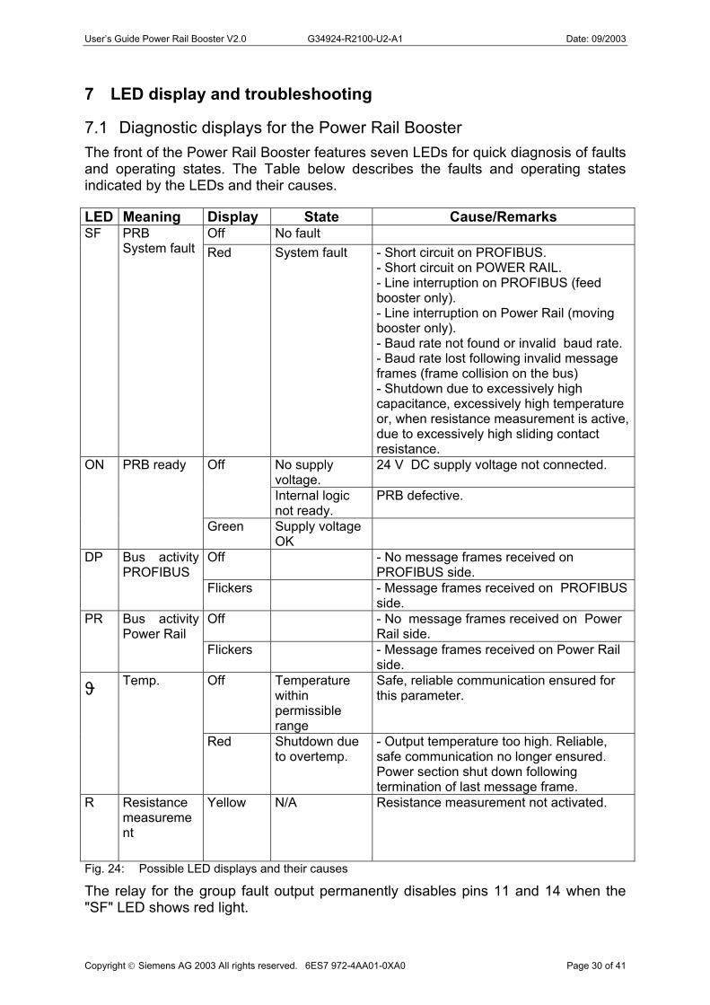
7.1 Diagnostic displays for the Power Rail Booster The front of the Power Rail Booster features seven LEDs for quick diagnosis of faults and operating states. The Table below describes the faults and operating states indicated by the LEDs and their causes.
LED Meaning Display State Cause/Remarks Off No fault SF PRB
System fault Red System fault - Short circuit on PROFIBUS. - Short circuit on POWER RAIL. - Line interruption on PROFIBUS (feed booster only). - Line interruption on Power Rail (moving booster only). - Baud rate not found or invalid baud rate. - Baud rate lost following invalid message frames (frame collision on the bus) - Shutdown due to excessively high capacitance, excessively high temperature or, when resistance measurement is active, due to excessively high sliding contact resistance.
No supply voltage.
24 V DC supply voltage not connected. Off
Internal logic not ready.
PRB defective.
ON PRB ready
Green Supply voltage OK
Off - No message frames received on PROFIBUS side.
DP Bus activity PROFIBUS
Flickers - Message frames received on PROFIBUS side.
Off - No message frames received on Power Rail side.
PR Bus activity Power Rail
Flickers - Message frames received on Power Rail side.
Off Temperature within permissible range
Safe, reliable communication ensured for this parameter. ϑ Temp.
Red Shutdown due to overtemp.
- Output temperature too high. Reliable, safe communication no longer ensured. Power section shut down following termination of last message frame.
R Resistance measurement
Yellow N/A Resistance measurement not activated.
Fig. 24: Possible LED displays and their causes
Copyright Siemens AG 2003 All rights reserved. 6ES7 972-4AA01-0XA0 Page 30 of 41
The relay for the group fault output permanently disables pins 11 and 14 when the "SF" LED shows red light.

User’s Guide Power Rail Booster V2.0 G34924-R2100-U2-A1 Date: 09/2003
7.2 Fault scenarios in a DP master system with PRBs The Figure below shows possible fault locations in a DP master system with Power Rail Boosters.
Fig. 25: Possible fault locations in a DP master system with Power Rail Boosters
Locations and displays for the various faults are listed below.
Copyright Siemens AG 2003 All rights reserved. 6ES7 972-4AA01-0XA0 Page 31 of 41
Fig. 26: Fault location
User’s Guide Power Rail Booster V2.0 G34924-R2100-U2-A1 Date: 09/2003
8 Technical specifications
Copyright Siemens AG 2003 All rights reserved. 6ES7 972-4AA01-0XA0 Page 32 of 41
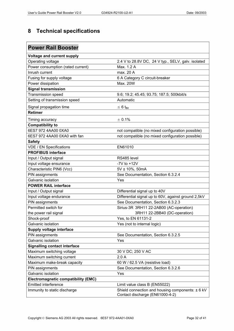
Power Rail Booster Voltage and current supply Operating voltage 2.4 V to 28.8V DC, 24 V typ., SELV, galv. isolated Power consumption (rated current) Max. 1.2 A Inrush current max. 20 A Fusing for supply voltage 6 A Category C circuit-breaker Power dissipation Max. 20W Signal transmission Transmission speed 9.6; 19.2; 45.45; 93.75; 187.5; 500kbit/s Setting of transmission speed Automatic
Signal propagation time ≤ 6 tBit Retimer
Timing accuracy ± 0.1% Compatibility to 6ES7 972 4AA00 0XA0 not compatible (no mixed configuration possible) 6ES7 972 4AA00 0XA0 with fan not compatible (no mixed configuration possible) Safety VDE / EN Specifications EN61010 PROFIBUS interface Input / Output signal RS485 level Input voltage ensurance -7V to +12V Characteristic PIN6 (Vcc) 5V ± 10%, 50mA PIN assignments See Documentation, Section 6.3.2.4 Galvanic isolation Yes POWER RAIL interface Input / Output signal Differential signal up to 40V Input voltage endurance Differential signal up to 60V, against ground 2,5kV PIN assignments See Documentation, Section 6.3.2.3 Permitted switch for Sirius-3R 3RH11 22-2AB00 (AC-operation) the power rail signal 3RH11 22-2BB40 (DC-operation) Shock-proof Yes, to EN 61131-2 Galvanic isolation Yes (not to internal logic) Supply voltage interface PIN assignments See Documentation, Section 6.3.2.5 Galvanic isolation Yes Signalling contact interface Maximum switching voltage 30 V DC; 250 V AC Maximum switching current 2.0 A Maximum make-break capacity 60 W / 62.5 VA (resistive load) PIN assignments See Documentation, Section 6.3.2.6 Galvanic isolation Yes Electromagnetic compatibility (EMC) Emitted interference Limit value class B (EN55022) Immunity to static discharge Shield connection and housing components: ± 6 kV Contact discharge (EN61000-4-2)

User’s Guide Power Rail Booster V2.0 G34924-R2100-U2-A1 Date: 09/2003
Power Rail Booster Immunity to high-frequency discharge Frequency range: 80 MHz to 1 GHz, test field intensity: 10 V/m at 80% amplitude modulation with 1 kHz. Range 87 MHz to 108 MHz, 174 MHz to 230 MHz and 470 MHz to 790 MHz: 3V/m Immunity to conducted interference Power and bus cables ± 2 kV (Burst)(EN61000-4-4)Immunity to conducted interference (surge) Power cables ± 1 kV symmetrical (Surge) Bus cables ± 2kV unsymmetrical (EN61000-4-5) Climatic service environment Ambient temperature 0 °C to +60 °C (IEC 68-2-1, IEC 68-2-2) Storage temperature –40 °C to +70 °C (IEC 68-2-14) Relative humidity <95 %, no condensation (IEC 68-2-30) Mechanical service environment Vibration during operation 10 to 58 Hz, 0.075 mm displacement; 58 to 150 Hz, 9.8 m/s 2 (1 g) acceleration (IEC 68–2–6) Vibration during transport 5 to 9 Hz, 3.5 mm displacement; 9 to 500 Hz, 9.8 m/s 2 (1 g) acceleration Type of protection IP20 Dimensions 90.1x132x74 (WxHxD) Mounting position Horizontal installation on vertical wall Weight 360g
Copyright Siemens AG 2003 All rights reserved. 6ES7 972-4AA01-0XA0 Page 33 of 41

User’s Guide Power Rail Booster V2.0 G34924-R2100-U2-A1 Date: 09/2003
9 Appendix
9.1 Examples for applications
9.1.1 Block sequence control
The block sequence control is used to minimize the communication losses in case of segment changes. This technology can be utilized both by PRB segment changes and by DP master segment changes.
Fig. 27: Examples for block sequence control
Operating sequence of a segment change:
the segment in the middle is switched to “neutral” a vehicle is approximating to the segment change area on PRB segment 1 the segment in the middle is switched to „PRB 1“ the vehicle is complete on the segment in the middle the segment in the middle is switched to „PRB 2“ the vehicle leave the segment change area on PRB segment 2 the segment in the middle is switched to “neutral”
Copyright Siemens AG 2003 All rights reserved. 6ES7 972-4AA01-0XA0 Page 34 of 41
As described in the chapter 4.4 „Rail sections“, all segments have to be separated electrically with special rail sections. If a vehicle stops on one of these rail sections, because there is already another vehicle in front, it cannot longer communicate with the central PLC. With the feature block sequence control, that can be prevented. If a vehicle stops on one of these rail sections in fact it looses for a very short time the communication, but after switching the rail section to the next master or booster, the communication can be continued.

User’s Guide Power Rail Booster V2.0 G34924-R2100-U2-A1 Date: 09/2003
9.2 CE label Product identification: Power Rail Booster 6ES7 972-4AA01-0XA0
EMC guideline: The product described in this manual is compliant with the following EU guidelines:
CE
Guideline 89/336/EWG "Electromagnetic Compatibility" Guideline 73/23/EWG "Electrical Resources For Use Within Specific Voltage Limits" (Low-voltage Guideline)
Application: The product is designed for use in the following applications:
Requirements regarding:
Application Emitted interference Interference
immunity
Industrial sector EN 61000-6-4: 2001 EN 61000-6-2: 1999
Installation guidelines: The product satisfies the requirements as long as the installation guidelines, operating guidelines and safety information presented in the "User's Guide for the Power Rail Booster" are carefully followed.
Certificates of conformity: The EU certificates of conformity are held for viewing by the appropriate authorities at:
Siemens Electronic Design and Manufacturing Services GmbH & Co. KG SEDM D&D DIT 1 Siemensstraße 33 D- 71254 Ditzingen
Copyright Siemens AG 2003 All rights reserved. 6ES7 972-4AA01-0XA0 Page 35 of 41
The Power Rail Booster is not a machine as defined by the EU's "Machines" guideline. There is therefore no certificate of conformity relating to the EU's "Machines" guideline 89/392/EWG for the interface module. The Power Rail Booster is part of the electrical components of a machine and must therefore be included by the machine manufacturer in the process culminating in a certificate of conformity.

User’s Guide Power Rail Booster V2.0 G34924-R2100-U2-A1 Date: 09/2003
9.3 Glossary
Automation system An automation system is a programmable controller consisting of at least one CPU, a variety of input and output modules, and HMI devices. Baud rate The baud rate is the speed at which data are transmitted, and specifies the number of bits transmitted per second (baud rate = bit rate). The Power Rail Booster can accommodate baud rates of between 9.6 kBaud to 500 kBaud. Bounce Single or repeated, coincidental or reproducible disengaging or re-engaging of a sliding contact from resp. with the contact rail. Bus Shared transmission path to which all nodes are connected; has two defined ends. On the Power Rail Booster, the bus is a two-wire line or a pair of contact rails. Bus connector Physical connector between bus node and bus cable. Contact rail Stationary component of a control rail system. Contact rail system A contact rail system consists of sliding contacts and contact rails. A contact rail system can be used to transport power and data, the contact rail system ensuring mobile contact between stationary and mobile components. Distributed I/O Distributed I/O are input/output units which are not plugged into the central controller, but are set up at a greater distance from the CPU, e.g. ET 200M, ET 200B, ET 200X, ET 200L, ET 200S Distributed I/O are connected to the DP master via PROFIBUS DP. Double rail section A rail section in "double" design to prevent short circuits between two contact rail segments, which can occur when a (double) sliding contact travels over a rail section. Double sliding contacts/Double collectors An arrangement of two primarily mechanical, independently supported sliding contacts, which together establish contact with a high level of contact stability. DP Distributed I/O DP master
Copyright Siemens AG 2003 All rights reserved. 6ES7 972-4AA01-0XA0 Page 36 of 41
A master with behavioural characteristics to Standard EN 50170, Volume 2, PROFIBUS is referred to as a DP master.

User’s Guide Power Rail Booster V2.0 G34924-R2100-U2-A1 Date: 09/2003
DP slave A slave that is operated on the PROFIBUS with the PROFIBUS DP protocol and has behavioural characteristics which accord with EN 50170, Volume 2, PROFIBUS is referred to as a DP slave. DP Standard The DP Standard is the bus protocol which can be transmitted over the Power Rail Booster to EN 50170, Volume 2, PROFIBUS. Equipotential bonding Electrical connection (equipotential bonding conductor) which brings the exposed conductive part(s) of an electrical device and extraneous conductive parts to the same or almost the same potential in order to prevent damaging or dangerous voltages between these parts. FO Fiber optics Ground Conductive ground whose electrical potential can be set to equal zero at any point. In the presence of a grounding electrode, ground can have a potential unequal zero. The term "reference potential" is often used to describe this set of circumstances. Isolated In isolated input/output modules, the reference potentials of control current circuit and load current circuit are galvanically isolated, e.g. by optical coupler, relay contact or transformer. Input/output current circuits can be connected to common potential. Isolating rail section A rail section on which the data contact rails are isolated over the length of a double sliding contact in order to prevent short circuits between two contact rail segments, which can occur when a (double) sliding contact travels over a rail section. Master When it has the Token, a master can send data to other nodes and request data from other nodes (= active node). DP masters are e.g. the CPU 315-2 DP or the IM 308-C. Non-isolated In non-isolated input/output modules, the reference potentials of control current circuit and load current circuit are electrically connected. OLM Optical Link Module PELF Protective Extra Low Voltage Power Rail Booster Amplifier for PROFIBUS. For transmitting bus signals via contact rail.
Copyright Siemens AG 2003 All rights reserved. 6ES7 972-4AA01-0XA0 Page 37 of 41

User’s Guide Power Rail Booster V2.0 G34924-R2100-U2-A1 Date: 09/2003
PR Power Rail PROFIBUS PROcess FIeld BUS, a German process- and fieldbus standard to EN 50170, Volume 2, PROFIBUS which defines functional, electrical and mechanical properties and characteristics for a bit-serial fieldbus system. PROFIBUS is available with DP (= Distributed I/Os), FMS (= Fieldbus Message Specification), PA (= Process Automation) or TF (= Technological Functions) protocol. PROFIBUS address Every bus node must have a PROFIBUS address for unambiguous identification of that node on the PROFIBUS. PCs/PGs have the PROFIBUS address "0". Reference potential Potential at which the voltages flowing through electrical circuits are viewed and/or measured. Segment The section of bus cable between two terminating resistors forms a segment. A PROFIBUS DP segment contains between 0 and 32 bus nodes. Segments can be joined to one another using RS485 repeaters. All galvanically connected contact rails form a contact rail segment. As many as 124 bus nodes can be operated on one contact rail segment. Segments can be coupled over RS485. SELF Safety Extra Low Voltage Self-cleaning The cleaning of contact rail and sliding contact caused by operation of the contact rail system. The movement of a sliding contact over a contact rail pushes aside dust particles and rubs off oxide layers. The greater the frequency of travel over a contact rail and the greater the pressure of the sliding contact against the rail, the greater the self-cleaning effect. SF Group fault Slave A slave may exchange data with a master only at the master's request. Slaves are e.g. all DP slaves, such as ET 200L, ET 200X, ET 200M, ET 200S, and so on. Sliding contact Mobile component of a contact rail system. tbit Bit duration, length of a bit To ground To ground means to connect an electrically conductive component with the grounding electrode via a grounding system.
Copyright Siemens AG 2003 All rights reserved. 6ES7 972-4AA01-0XA0 Page 38 of 41

User’s Guide Power Rail Booster V2.0 G34924-R2100-U2-A1 Date: 09/2003
Transfer resistance Electrical resistance between a contact rail and a sliding contact during travel. The transfer resistance depends on the amount of contamination on sliding contact and contact rail, as well as on the oxidation of both their surfaces. Zero potential
Copyright Siemens AG 2003 All rights reserved. 6ES7 972-4AA01-0XA0 Page 39 of 41
Zero potential is seen as the entirety of all interconnected inactive electrical parts of a device which cannot assume a dangerous level of touch voltage even in the event of a fault.

User’s Guide Power Rail Booster V2.0 G34924-R2100-U2-A1 Date: 09/2003
10 List of Figures
Fig. 1: Sample application for the Power Rail Booster ........................................................................ 9 Fig. 2: Block diagram of a DP master segment with two PRB segments .......................................... 12 Fig. 3: Example of cascading ............................................................................................................. 13 Fig. 4: Example of a point-to-point connection................................................................................... 13 Fig. 5: Example of line topology......................................................................................................... 14 Fig. 6: Example of star topology......................................................................................................... 14 Fig. 7: Example of a closed loop........................................................................................................ 15 Fig. 8: Example of a double rail section ............................................................................................. 16 Fig. 9: Example of an isolating rail section......................................................................................... 16 Fig. 10: Maximum rail length depending on the selected transmission speed .................................. 19 Fig. 11: The PRB Checker configuring tool – input screen form........................................................ 19 Fig. 12: Configuring the network parameters in Step 7's Hardware Configuration............................ 20 Fig. 13: Front view of the Power Rail Booster. Location of................................................................ 24 Fig. 14: Installing a PRB on a standard mounting rail........................................................................ 25 Fig. 15: Overview of interfaces on the Power Rail Booster ............................................................... 26 Fig. 16: Wiring guidelines for the interfaces of the PRB .................................................................... 26 Fig. 17: Terminal assignment for the Power Rail interface ................................................................ 27 Fig. 18: Terminal assignment for the PROFIBUS RS485 interface................................................... 27 Fig. 19: Terminal assignment for the supply voltage interface .......................................................... 28 Fig. 20: Terminal assignment for the signalling contact interface...................................................... 28 Fig. 21: Connection scheme PRB...................................................................................................... 28 Fig. 22: Measuring the series resistances on individual double sliding contacts............................... 29 Fig. 23: Measuring the series resistances on both double sliding contacts....................................... 29 Fig. 24: Possible LED displays and their causes............................................................................... 30 Fig. 25: Possible fault locations in a DP master system with Power Rail Boosters........................... 31 Fig. 26: Fault location......................................................................................................................... 31
Copyright Siemens AG 2003 All rights reserved. 6ES7 972-4AA01-0XA0 Page 40 of 41
Fig. 27: Examples for block sequence control ................................................................................... 34

User’s Guide Power Rail Booster V2.0 G34924-R2100-U2-A1 Date: 09/2003
Continually updated information
You can find the very latest information on SIMATIC products on the Internet at http://www.ad.siemens.de/ In addition, SIMATIC Customer Support also provides support in the form of new information and downloads which may prove useful in helping you with your SIMATIC products. _ On the Internet at http://www.ad.siemens.de/support/html_00/index.shtml _ Through the SIMATIC Customer Support Mailbox under the number: +49 (911) 895-7100
Copyright Siemens AG 2003 All rights reserved. 6ES7 972-4AA01-0XA0 Page 41 of 41
To select the mailbox, you must use a modem with a speed of up to V.34 (28.8 kBaud) and set the modem parameters as follows: 8, N, 1, ANSI, or call in over ISDN (x.75, 64 kBit). You can reach SIMATIC Customer Support by phone at +49 (911) 895-7000 and by fax at +49 (911) 895-7002. If you have any questions, you can either send an e-mail over the Internet or leave mail in the mailbox given above.