Embed Size (px)
Citation preview
User’s Guide Mac OS X Version
Hammerfall® DSP System
RPM
Mobile Turntable / CD / MIC / MIDI Interface PCI Busmaster Digital I/O System
PCI and CardBus Interface 24 Bit / 96 kHz
TotalMix™
24 Bit / 96 kHz üü
SyncAlign® ZLM®
User’s Guide HDSP System RPM © RME 2
Contents 1 Introduction............................................................ 3 2 Package Contents .................................................. 3 3 System Requirements............................................ 3 4 Brief Description and Characteristics ................... 4 5 Technical Specifications
5.1 Digital.................................................................... 4 5.2 Analog................................................................... 4 5.3 MIDI ...................................................................... 5 5.4 Power Supply ........................................................ 5
6 Hardware Installation 6.1 PCI Interface......................................................... 6 6.2 CardBus Card ....................................................... 6
7 Driver Installation................................................... 7 8 Flash Update .......................................................... 7 9 Features and Limitations ....................................... 8 10 Mac OS X FAQ
10.1 Round about Driver Installation............................ 9 10.2 MIDI doesn't work ................................................ 9 10.3 Which Sample Rates are supported....................10 10.4 Repairing Disk Permissions ................................10 10.5 PCI card and PCI slot compatibility.....................10
11 Operation and Usage 8.1 Connections .........................................................11 8.2 Recording.............................................................12 8.3 Analog Inputs .......................................................12 8.4 Analog Outputs.....................................................13
12 Configuring the RPM ............................................14 13 Disconnect Mode ..................................................15 14 Bypass Mode .........................................................15 15 TotalMix: Routing and Monitoring .......................16
15.1 Elements of the Surface .....................................17 15.2 Tour de TotalMix ................................................18 15.3 Submix View ......................................................19 15.4 Mute and Solo ....................................................19 15.5 Hotkeys ..............................................................19 15.6 Quick Access Panel............................................20 15.7 Presets ...............................................................21 15.8 Menu Options .....................................................22 15.9 Level Meter ........................................................22
16 The Matrix 16.1 Elements of the Surface .....................................23 16.2 Usage.................................................................23 16.3 Advantages of the Matrix....................................24
17 TotalMix Super-Features 17.1 Selection and Group-based Operation................24 17.2 Copy Routings to other Channels .......................25 17.3 Delete Routings..................................................25
18 Notes on Laptops and CardBus ...........................26 19 Hotline – Troubleshooting....................................27 21 Accessories ...........................................................27 22 TECH INFO ............................................................28 23 Warranty ................................................................29 24 Appendix ...............................................................29 25 Block Diagram RPM ..............................................30 26 CE / FCC Compliance............................................31
User’s Guide HDSP System RPM © RME 3
1. Introduction Thank you for choosing the RPM. This unique audio system is the perfect tool for DJs, home recording and professional entertainers. It connects microphone, turntable, CD player and other analog sources directly to a computer. Installation is simple, even for the inexperienced user, thanks to the latest Plug and Play technology and full interrupt-sharing. The numerous unique features and well thought-out configuration dialog puts the Hammerfall DSP at the very top of the range of digital audio interface cards. The package includes drivers for Mac OS X 10.2.8 or higher. Our high-performance philosophy guarantees maximum system performance by executing all functions directly in hardware and not in the driver (i.e. the CPU). 2. Package Contents Please check that your Hammerfall DSP System's package contains each of the following: PCI Interface: • PCI card HDSP • Quick Info guide • RME Driver CD • Cable IEEE1394, 4.5 m (15 ft) • Internal cable (3 pin) CardBus Interface: • CardBus card • Quick Info guide • RME Driver CD • Cable CardBus to IEEE1394, 4.5 m (15 ft) • 12 V car cable • Battery cable • Power supply 12 V / 1.25 A and power cord RPM: • I/O-box RPM • Quick Info guide • RME Driver CD 3. System Requirements • Mac OS 10.2.8 or up • PCI Interface: a free PCI rev. 2.1 Busmaster slot • CardBus Interface: a free PCMCIA Slot type II, CardBus-compatible
User’s Guide HDSP System RPM © RME 4
4. Brief Description and Characteristics • 2 high quality phono inputs with RIAA compensation • 1 microphone input with Class-A frontend • Level adjustment in hardware ensures highest dynamic ratio • All settings can be changed in real-time • 8 available buffer sizes/latencies: 1.5 / 3 / 6 / 12 / 23 / 46 / 93 / 186 ms • Zero Latency Monitoring: Hardware bypass per track, controlled by Punch in/out • Enhanced ZLM for latency-free submixes • SyncAlign guarantees sample aligned and never swapping channels • 1 x MIDI I/O, 16 channels high-speed MIDI • 1 x Analog Line/headphone output, separate output for independent submix • DIGICheck DSP: Level meter in hardware, peak- and RMS calculation • TotalMix: 102 channel mixer with 40 bit internal resolution 5. Technical Specifications 5.1 Digital • Internal sample rates: 32 / 44.1 / 48 / 88.2 / 96 kHz • Internal resolution: 24 Bit 5.2 Analog AD Phono Input • Resolution AD: 24 Bit • Frequency response (RIAA), ± 1 dB: 40 Hz - 20 kHz • Maximum input level (0 dBFS), 1 kHz: -23 dBu, 54 mV • Signal to Noise Ratio (SNR): 87 dB RMS unweighted, 96 dBA • THD: < -93 dB, < 0.002 % • THD+N: < -83 dB, < 0.007 % • Channel separation @ 1 kHz: > 100 dB • Input impedance: 30 kOhm • Input capacity: 220 pF AD Line Input • Resolution AD: 24 Bit • Frequency response AD @ 44.1 kHz, -0.5 dB: 5 Hz - 20.7 kHz • Frequency response AD @ 96 kHz, -0.5 dB: 5 Hz - 32 kHz • Signal to Noise ratio: 10 dB RMS unweighted, 106 dBA • THD: < -100 dB, < 0.001 % • THD+N: < -93 dB, < 0.002 % • Channel separation @ 1 kHz: > 100 dB • Input: RCA, unbalanced • Input impedance @ Line 0 dB: 30 kOhm • Input impedance @ Line -6 dB: 2 kOhm • Input level for 0 dBFS @ Line 0 dB: +2.5 dBu, 1 V RMS • Input level for 0 dBFS @ Line –6 dB: +8.5 dBu, 2 V RMS
User’s Guide HDSP System RPM © RME 5
AD Mic Input • Resolution AD: 24 Bit • Frequency response AD @ 44.1 kHz, -0.5 dB: 5 Hz – 20.7 kHz • Frequency response AD @ 96 kHz, -0.5 dB: 5 Hz - 32 kHz • Signal to Noise ratio (SNR): 100 dB RMS unweighted, 106 dBA • THD: < -100 dB, < 0.001 % • THD+N: < -93 dB, < 0.002 % • Input: 6.3 mm TRS (stereo) / XLR combo jack, servo-balanced • Input impedance: 2 kOhm DA • Resolution DA: 24 Bit • Signal to Noise ratio: 108 dB RMS unweighted, 111 dBA (unmuted) • Frequency response DA @ 44.1 kHz, -0.5 dB: 5 Hz – 20.9 kHz • Frequency response DA @ 96 kHz, -0.5 dB: 5 Hz - 35 kHz • THD: < - 98 dB, < 0.0013 % • THD+N: < -91 dB, < 0.002 % • Channel separation: > 100 dB • Maximum output level RCA unbalanced: +8 dBu, 2 V RMS • Maximum output level TRS balanced: +14 dBu, 4 V RMS • Output impedance: 220 Ohm Phones • Resolution DA: 24 Bit • Frequency response DA, -0.1 dB: 20 Hz - 20.8 kHz (sf 44,1 kHz) • Frequency response DA, -0.5 dB: 10 Hz - 44 kHz (sf 96 kHz) • Signal to Noise Ratio (SNR): 108 dB (RMS unweighted, unmuted), 111 dBA • THD: < - 98 dB, < 0.0013 % • THD+N: < -91 dB, < 0.002 % • Channel separation: > 100 dB • Maximum output level: +8 dBu • Ouput impedance: 30 Ohm 5.3 MIDI • 1 x MIDI I/O via 5-pin DIN sockets • PCI bus based hi-speed operation • Separate 128 byte FIFO for input and output • MIDI state machine in hardware for reduced interrupt request load 5.4 Power supply • The CardBus card does not provide power to the RPM. Therefore a hi-tech switching power
supply is included • The PCI card operates as power supply for the attached RPM via the FireWire cable The RPM draws a high startup current of more than 2 A during initialisation. Current at 12 Volt operating voltage: unloaded 250 mA (3 Watts), loaded 560 mA (7 Watts). Supply voltage range DC 10 V – 15 V. The center pin of the AUX jack is Plus. The unit includes protection against reversed polarity of the power supply.
User’s Guide HDSP System RPM © RME 6
6. Hardware Installation 6.1 PCI Interface
Before installing the PCI card, please make sure the computer is switched off and the power cable is disconnected from the mains supply. Inserting or removing a PCI card while the computer is in operation can cause irreparable damage to both motherboard and card!
1. Disconnect the power cord and all other cables from the computer. 2. Remove the computer's housing. Further information on how to do this can be obtained
from your computer´s instruction manual. 3. Important: Before removing the card from its protective bag, discharge any static in your
body by touching the metal chassis of the PC. 4. Insert the PCI card firmly into a free PCI slot, press and fasten the screw. 5. Replace the computer's housing. 6. Reconnect all cables including the power cord. 7. Connect PCI interface and RPM using the supplied cable (IEEE1394). This is a standard
FireWire cable (6-pin). 6.2 CardBus Card Before inserting the CardBus card make sure the complete HDSP system is ready for operation! 1. Connect the CardBus card with the RPM using the supplied cable. 2. Insert the CardBus card with the Hammer logo up into a PCMCIA slot. 3. Plug the power jack of the supplied switching power supply into the connector labeled AUX,
on the rear of the RPM. 4. Connect power cord to power supply, plug into AC outlet. The green LED of the power
supply and the red LED of the RPM will light up. 5. Switch on the notebook and boot the operating system.
The small 15-pin connector of the CardBus card is coded. Only the supplied special cable can be plugged in, and only when the metal sleeve is up. Any kind of violence when plugging in and out can cause damage to the CardBus card.
User’s Guide HDSP System RPM © RME 7
7. Driver Installation First fit the card (see 6. Hardware Installation), then switch on the computer and install the drivers from the RME Driver CD. The driver files are located in the folder 'Hammerfall DSP'. Installation works automatically by a double-click on the file hdsp.mpkg. In case a newer driver version was downloaded from the RME website: Double-click onto hdsp_xx.gz to expand the archive file to hdsp_xx.tar and the folder HDSP, which includes the driver file hdsp.mpkg. Installation works automatically by a double-click on this file. The folder HDSP also includes the Settings dialog and the HDSP mixer (TotalMix). These two programs can be copied into any folder, but have to be started at each boot at least once, in order to transfer the stored settings to the hardware. We recommend to add both programs to System Preferences/Login Items. Using the option ’Hide’ both programs stay minimized in the Dock when booting. Note: since 10.3 (Panther) Login Items is found in System Preferences/User. Reboot the computer when installation is done. In case of a driver update it's not necessary to remove the old driver first, it will be overwritten during the installation. But please check the entries for the Login Items, to prevent the older settings dialog from being loaded unnoticed. 8. Flash Update The Flash Update Tool updates the HDSP PCI and CardBus card to the latest version. It requires an already installed driver. Start the program HDSP Flash. The Flash Update Tool displays the current revision of the HDSP interface, and whether it needs an update or not. If so, then please manually select if a PCI card (desktop computer) or a CardBus card (laptop) shall be flashed. Next simply press the 'Update' button. A progress bar will indicate when the flash process is finished. The bar moves slowly first (program), then faster (verify). If more than one interface card is installed, all cards can be flashed by changing to the next tab and repeating the process. After the update the PCI/CardBus cards need to be resettet. This is done by powering down and shutting off the PC. A warm boot is not enough! PCI card revision 1.8 or up (black PCB): When the update fails (status: failure), the card's second BIOS will be used from the next cold boot on (Secure BIOS Technology). Therefore the card stays fully functional. The flash process should then be tried again on a different computer. All other PCI cards and all CardBus cards: When the update fails (status: failure) the flash process should be repeated several times, until no error message occurs anymore. If the failure message is displayed nonetheless, the interface will most propably no longer work when the computer is switched off and on again. The interface then has to be re-programmed at the factory. We have invested a lot of work to prevent the system from getting in this state. If it happens despite our efforts, the best advice we can give is to not switch off the computer! As long as it is not switched off the old programming of the PCI/CardBus interface will stay active, and you can continue to work with the system using the old drivers.
User’s Guide HDSP System RPM © RME 8
9. Features and Limitations This driver was tested under Jaguar 10.2.8 and Panther only. Older versions of OS X are not and will not be supported. This OS X driver operates in non-interleave mode. It works for example using iTunes, Cubase SX, Nuendo, Live 1.5.2, Peak 3.1, VSamp 3.2.7, Spark (from version 2.6), Logic 5.4 and Reason 2.5. Via System Preferences / Audio-MIDI Setup the hardware can be configured for the system wide usage. Programs that don't support card or channel selection will use the device selected as Standard-Input and Standard-Output. (Soundstudio, Mplayer, Amplitube etc.). In the lower part of the window, the audiohardware's capabilities are shown and can be changed in some cases. On the record side no changes are possible. Programs that don't support channel selection will always use channels 1/2, the first stereo pair. Since OS X 10.3 playback can be configured freely and to any of the available playback channels. This is done via Speaker Setup. Even multichannel playback (Surround, DVD Player) can be set up easily. Multicard Operation OS X supports more than one audio card, even when used at the same time. Please note that at this time the only multicard-capable software known to us is Digital Performer. As the RPM does not include digital interfaces – and therefore no synchronization capabilities - an operation of multiple RPM will lead to a slow drift of the units. Each RPM uses an internal quartz as time reference. These quartz are not completely identical. A long-term playback or a recording on multiple tracks will have deviations in form of small position differences (timing drift). Synchronisation The RPM can be synchronized to MTC or MIDI clock. In both cases, the used software is repsonsible for proper synchronization to other devices. In case a project includes audio tracks, the software must be capable of recalculating the audio data in realtime to the speed of the MIDI data (Sample Rate Conversion, resampling).
User’s Guide HDSP System RPM © RME 9
10. Mac OS X FAQ 10.1 Round about Driver Installation The driver with the file suffix gz provided by RME is a compressed TAR archive. TAR bundles multiple files and folders into one file, but does not save memory space nor download time. Both TAR and gz are supported natively by OS X, a double click on the file is all you need to do. Older browsers do not recognize gz as an archive, loading the file as a document. This results in a cryptic looking text within the browser window. Downloading the file can be done via the right mouse key, Save Target as. Despite this procedure, some older browsers like Netscape 4.78 will not save the file correctly - the archive will be corrupted. The driver consists of a package file (pkg), which contains various folders and files, similar to TAR. A double click will start the OS X installer. To save you the hassle of installing both audio and MIDI drivers separately, the HDSP series driver contains an additional meta package (mpkg), that points to the single packages. Those single packages are not shown in the Finder, as they reside within the invisible folder '.contained_packages'. Only the mpkg is visible. Important: an installation can only be done with the complete folder. If only the mpkg is copied to a different place, it will not find the single driver packages! The actual audio driver appears as a kernel extension file. The installer copies it to System / Library / Extensions. It's name is HammerfallDSP.kext. It is visible in the Finder, allowing you to verify date and driver version. Yet, in fact this again is a folder containing subdirectories and files. Nonetheless, this 'driver file' can be removed by simply dragging it to the trash bin. This can be helpful in case a driver installation fails. An incomplete installation can currently (10.3.2) only be detected indirectly: The installation routine does not open a message window with a note about a restart of the computer. This indicates that the driver file was not copied and the driver was not installed! Several users have observed that the installation routine occasionally stops and no longer works correctly. This can be fixed by removing the corresponding extension file prior to installation. In some cases, also (or only) a repair of the disk permission will help. We have also received reports saying the driver update could not be installed on the system disk - shown red crossed during the installation. Repairing permission may also help here. If not, we're sorry, but have to recommend to contact Apple. Our driver has no knowledge of folders, disks etc., the installation is handled completely by the OS X installer. 10.2 MIDI doesn't work
In some cases MIDI does not work after the installation of the HDSP driver. To be precise, applications do not show an installed MIDI port. The reason for this is usually visible within the Audio MIDI Setup. It displays no RME MIDI device, or the device is greyed out and therefore inactive. Mostly, removing the greyed out device and searching for MIDI devices again will solve the problem. If this does not help, we recommend manual removal of the MIDI driver and reinstallation of the complete driver. Otherwise repairing permissions may help. The HDSP MIDI driver is a plugin. During installation it will be copied to Library / Audio / MIDI Drivers. It's name is Hammerfall DSP MIDI.plugin. The file can be displayed in the Finder and also be removed by simply dragging it to the trash bin.
User’s Guide HDSP System RPM © RME 10
10.3 Which Sample rates are supported? RME's Mac OS X driver supports all sampling frequencies provided by the hardware. This includes 32 kHz and 64 kHz, and even 88.2 kHz and 96 kHz for the RPM. But not every software will support all the hardware's sample rates. For example Spark does not display 32 kHz and 64 kHz. The hardware's capabilities can easily be verified in the Audio MIDI Setup. Select Audio devices under Properties of: and choose the RME card. A click on Format will list the supported sample frequencies. Selecting a sample rate will immediately set the device to this frequency, which can be verified in the RME card's settings dialog (System Clock). Format thus allows you to activate any sampling frequency quickly and easily. 10.4 Repairing Disk Permissions Repairing permission can solve problems with the installation process - plus many others. To do this, launch Disk Utility located in Utilities. Select your system drive in the drive/volume list to the left. The First Aid tab to the right now allows you to check and repair disk permissions. 10.5 PCI card and PCI slot compatibility Unfortunately not every RME card will work in every PCI slot of an Apple computer. To our knowledge, the current Hammerfall DSP systems can be used in any PCI slot of all G4 and G5 models. In case additional PCI cards of any manufacturer are used, it might happen that the RME card is no longer found from the system. Swapping cards between slots can be helpful in this case.
User’s Guide HDSP System RPM © RME 11
11. Operation and Usage 11.1 Connections The front of the I/O-box RPM has the microphone input, MIDI input and output, the headphone output, and several status LEDs: Microphone In allows to connect a microphone via XLR or 1/4" TRS jack. Using the GAIN knob the sensitivity is adjusted to match the currently used microphone. The CLIP LED visualizes overload, caused by too high input level or wrong Gain adjustment. The LED lights up 4 dB before reaching the highest possible (undistorted) level. MIDI IN and OUT represent the MIDI input and output, realized as 5-pin DIN jacks. MIDI State indicates sent or received data for the MIDI port The red HOST LED lights up constantly when the power supply or the computer is switched on, thus signalling the presence of operating voltage. At the same time it operates as Error LED, in case the I/O-box wasn’t initialised, or the connection to the interface has been interrupted (Error, cable not connected etc.). The latter causes the LED to flash. After the firmware has been loaded into the I/O-box the LED extinguishes, thus signalling an error-free operation. Phones is a low impedance line output of highest quality, which can produce a sufficient and undistorted volume even when used with low-impedance headphones. The volume for the headphones is controlled with the VOL knob. The back of the RPM has the 4 analog inputs and outputs and the power supply connector AUX (only needed in CardBus operation). The PHONO/LINE INPUTS 1/2 and 3/4 can be used with turntables (moving magnet) or Line-based devices (CD player etc.). Operation is controlled in the Settings dialog. OUTPUTS 1/2 are provided as both RCA jacks (unbalanced) and as stereo TRS jacks (balanced). OUTPUTS 3/4 are only available as RCA jacks (unbalanced). The hook serves as strain relief. Originally only intended to secure the power supply cable (simply tie it around the hook, or tie a knot around it), the hook is big enough to hold several of the cables connected to the RPM.
User’s Guide HDSP System RPM © RME 12
11.2 Recording For recordings via the analog inputs the corresponding record device has to be chosen (RPM Analog (x+x)). The sensitivity of the phono and line inputs can be adjusted coarse in the Settings dialog. In real world operation, a further fine-adjustment prooves not to be necessary. Using line sources, the analog level can usually be controlled directly at the source to match the RPM's sensitivity perfectly. The sample frequency shown in the Settings dialog (see chapter 12, screenshot Settings) is useful as a quick display of the RPM's current configuration. It often makes sense to monitor the input signal or send it directly to the output. This can be done at zero latency using TotalMix (see chapter 15). 11.3 Analog Inputs One of the main issues when working with an AD-converter is to maintain the full dynamic range within the best operating level. The RPM includes a discreet hardware level adjustment which allows for a perfect adaptation of both line and phono inputs. While this setting is controlled by software, it operates at hardware level. This way, a maximum dynamic range and sound quality can be guaranteed. The following input options are avilable: • Phono +6 dB: amplifies the phono signal by 6 dB. Maintains a sufficient level for the AD-
converter even with low level cartridges and low volume longplay records. • Phono 0 dB: default sensitivity, matches most cartridges and longplay records • Phono –6 dB: loweres the phono signal by 6 dB. May be necessary when cartridges or
longplay records provide extreme levels. • Line 0 dB: default sensitivity, matches most tape decks • Line –6 dB: lowers the Line signal by 6 dB. Matches most CD-players and other line
sources. In case the analog line input is overloaded despite a setting of –6 dB (see Level Meters of TotalMix), the output signal of the connected device must be lowered. When the device's line outputs do not provide output level adjustment, a useful alternative can be to use its headphone output, as these can be adjusted nearly always. A simple cable adapter stereo TRS jack to 2 x RCA is available in many stores (see next page). The phono inputs not only heavily amplify the very low level signal of the cartridge, but also correct the frequency response according to RIAA. Bass will be raised, treble will be reduced significantly. Overall a linear frequency response is achieved. Due to the very low input signal, the high amplification and the heavy bass boost, phono inputs do not show Signal to Noise ratios and THD values as known from Line inputs. At first view a SNR of 85 dB seems to be terrible, as even 16 bit of dynamic range (96 dB) aren't achieved. This value has to be put into perspective, which happens the moment you put the needle on the longplay record. Even a 'perfect' empty record produces an unavoidable noise of about –60 dB, far away from the quality of the RPM's phono circuitry and AD-converters. The RPM includes a fixed first order high-pass filter, also known as rumble filter (although such filters never removed the typical rumble noise, as those 'needle grinding sounds' are found far above 150 Hz). The corner frequency of 35 Hz is very low, preventing audible sound changes. However while testing the RPM this filter has been found to be very useful to remove low frequency problems. Such signals are generated not only when scratching, but also by simple mechanical feedback, or by the uneven longplay record itself.
User’s Guide HDSP System RPM © RME 13
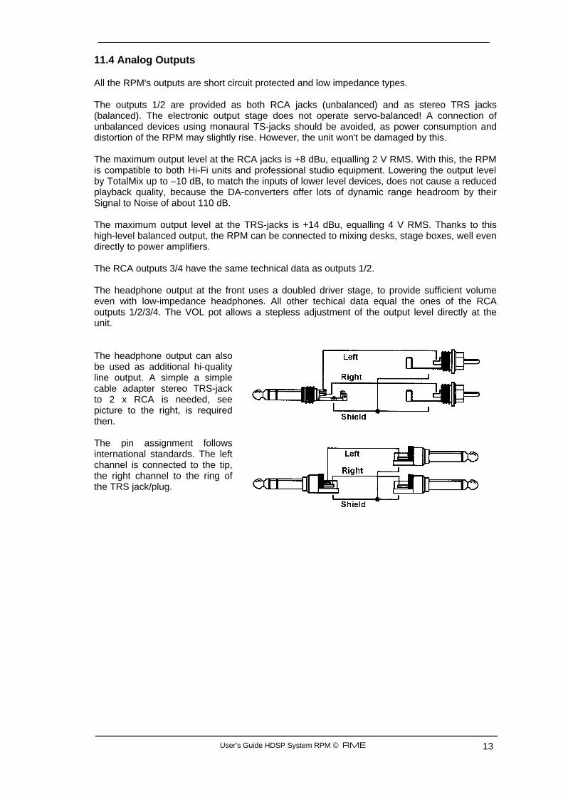
11.4 Analog Outputs All the RPM's outputs are short circuit protected and low impedance types. The outputs 1/2 are provided as both RCA jacks (unbalanced) and as stereo TRS jacks (balanced). The electronic output stage does not operate servo-balanced! A connection of unbalanced devices using monaural TS-jacks should be avoided, as power consumption and distortion of the RPM may slightly rise. However, the unit won't be damaged by this. The maximum output level at the RCA jacks is +8 dBu, equalling 2 V RMS. With this, the RPM is compatible to both Hi-Fi units and professional studio equipment. Lowering the output level by TotalMix up to –10 dB, to match the inputs of lower level devices, does not cause a reduced playback quality, because the DA-converters offer lots of dynamic range headroom by their Signal to Noise of about 110 dB. The maximum output level at the TRS-jacks is +14 dBu, equalling 4 V RMS. Thanks to this high-level balanced output, the RPM can be connected to mixing desks, stage boxes, well even directly to power amplifiers. The RCA outputs 3/4 have the same technical data as outputs 1/2. The headphone output at the front uses a doubled driver stage, to provide sufficient volume even with low-impedance headphones. All other techical data equal the ones of the RCA outputs 1/2/3/4. The VOL pot allows a stepless adjustment of the output level directly at the unit. The headphone output can also be used as additional hi-quality line output. A simple a simple cable adapter stereo TRS-jack to 2 x RCA is needed, see picture to the right, is required then. The pin assignment follows international standards. The left channel is connected to the tip, the right channel to the ring of the TRS jack/plug.
User’s Guide HDSP System RPM © RME 14
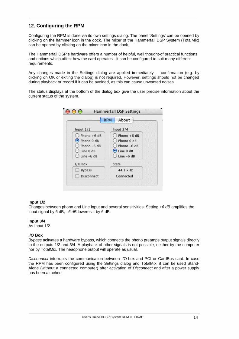
12. Configuring the RPM Configuring the RPM is done via its own settings dialog. The panel 'Settings' can be opened by clicking on the hammer icon in the dock. The mixer of the Hammerfall DSP System (TotalMix) can be opened by clicking on the mixer icon in the dock. The Hammerfall DSP’s hardware offers a number of helpful, well thought-of practical functions and options which affect how the card operates - it can be configured to suit many different requirements. Any changes made in the Settings dialog are applied immediately - confirmation (e.g. by clicking on OK or exiting the dialog) is not required. However, settings should not be changed during playback or record if it can be avoided, as this can cause unwanted noises. The status displays at the bottom of the dialog box give the user precise information about the current status of the system. Input 1/2 Changes between phono and Line input and several sensitivities. Setting +6 dB amplifies the input signal by 6 dB, –6 dB loweres it by 6 dB. Input 3/4 As Input 1/2. I/O Box Bypass acitvates a hardware bypass, which connects the phono preamps output signals directly to the outputs 1/2 and 3/4. A playback of other signals is not possible, neither by the computer nor by TotalMix. The headphone output will operate as usual. Disconnect interrupts the communication between I/O-box and PCI or CardBus card. In case the RPM has been configured using the Settings dialog and TotalMix, it can be used Stand-Alone (without a connected computer) after activation of Disconnect and after a power supply has been attached.
User’s Guide HDSP System RPM © RME 15
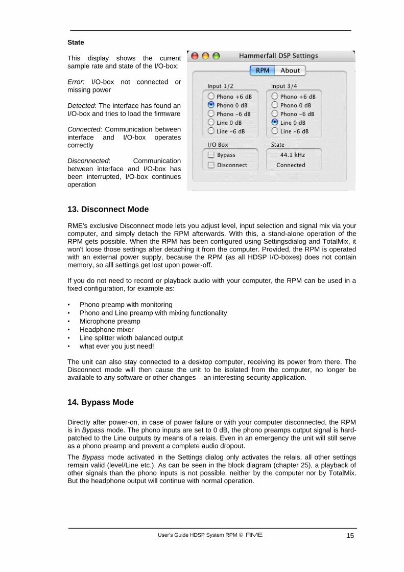
State This display shows the current sample rate and state of the I/O-box: Error: I/O-box not connected or missing power Detected: The interface has found an I/O-box and tries to load the firmware Connected: Communication between interface and I/O-box operates correctly Disconnected: Communication between interface and I/O-box has been interrupted, I/O-box continues operation 13. Disconnect Mode RME's exclusive Disconnect mode lets you adjust level, input selection and signal mix via your computer, and simply detach the RPM afterwards. With this, a stand-alone operation of the RPM gets possible. When the RPM has been configured using Settingsdialog and TotalMix, it won't loose those settings after detaching it from the computer. Provided, the RPM is operated with an external power supply, because the RPM (as all HDSP I/O-boxes) does not contain memory, so alll settings get lost upon power-off. If you do not need to record or playback audio with your computer, the RPM can be used in a fixed configuration, for example as: • Phono preamp with monitoring • Phono and Line preamp with mixing functionality • Microphone preamp • Headphone mixer • Line splitter wioth balanced output • what ever you just need! The unit can also stay connected to a desktop computer, receiving its power from there. The Disconnect mode will then cause the unit to be isolated from the computer, no longer be available to any software or other changes – an interesting security application. 14. Bypass Mode
Directly after power-on, in case of power failure or with your computer disconnected, the RPM is in Bypass mode. The phono inputs are set to 0 dB, the phono preamps output signal is hard-patched to the Line outputs by means of a relais. Even in an emergency the unit will still serve as a phono preamp and prevent a complete audio dropout.
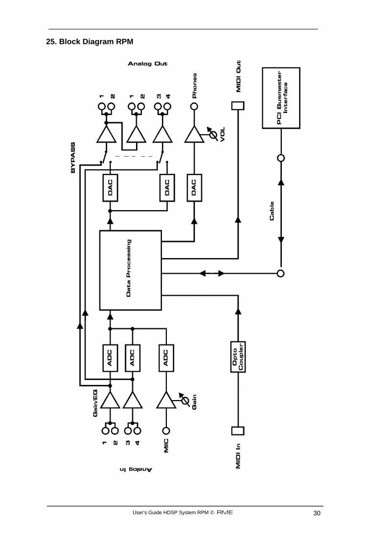
The Bypass mode activated in the Settings dialog only activates the relais, all other settings remain valid (level/Line etc.). As can be seen in the block diagram (chapter 25), a playback of other signals than the phono inputs is not possible, neither by the computer nor by TotalMix. But the headphone output will continue with normal operation.
User’s Guide HDSP System RPM © RME 16
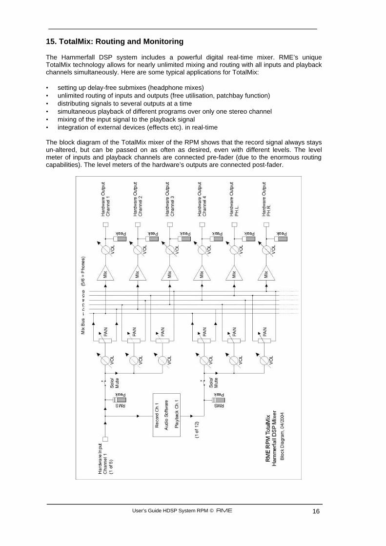
15. TotalMix: Routing and Monitoring The Hammerfall DSP system includes a powerful digital real-time mixer. RME’s unique TotalMix technology allows for nearly unlimited mixing and routing with all inputs and playback channels simultaneously. Here are some typical applications for TotalMix: • setting up delay-free submixes (headphone mixes) • unlimited routing of inputs and outputs (free utilisation, patchbay function) • distributing signals to several outputs at a time • simultaneous playback of different programs over only one stereo channel • mixing of the input signal to the playback signal • integration of external devices (effects etc). in real-time The block diagram of the TotalMix mixer of the RPM shows that the record signal always stays un-altered, but can be passed on as often as desired, even with different levels. The level meter of inputs and playback channels are connected pre-fader (due to the enormous routing capabilities). The level meters of the hardware’s outputs are connected post-fader.
User’s Guide HDSP System RPM © RME 17
15.1 Elements of the Surface The visible design of the mixer is mainly determined by the architecture of the HDSP system: • Upper row: hardware inputs. The level shown is that of the input signal, i. e. Fader
independent. Per fader and routing window, any input channel can be routed and mixed to any hardware output (third row).
• Middle row: playback channels (playback tracks of the software). Per fader and routing window, any playback channel can be routed and mixed to any hardware output (third row).
• Lower row: hardware outputs. Because they refer to the output of a subgroup, the level can only be attenuated here (in order to avoid overloads), routing is not possible. This row has two additional channels, the analog outputs.
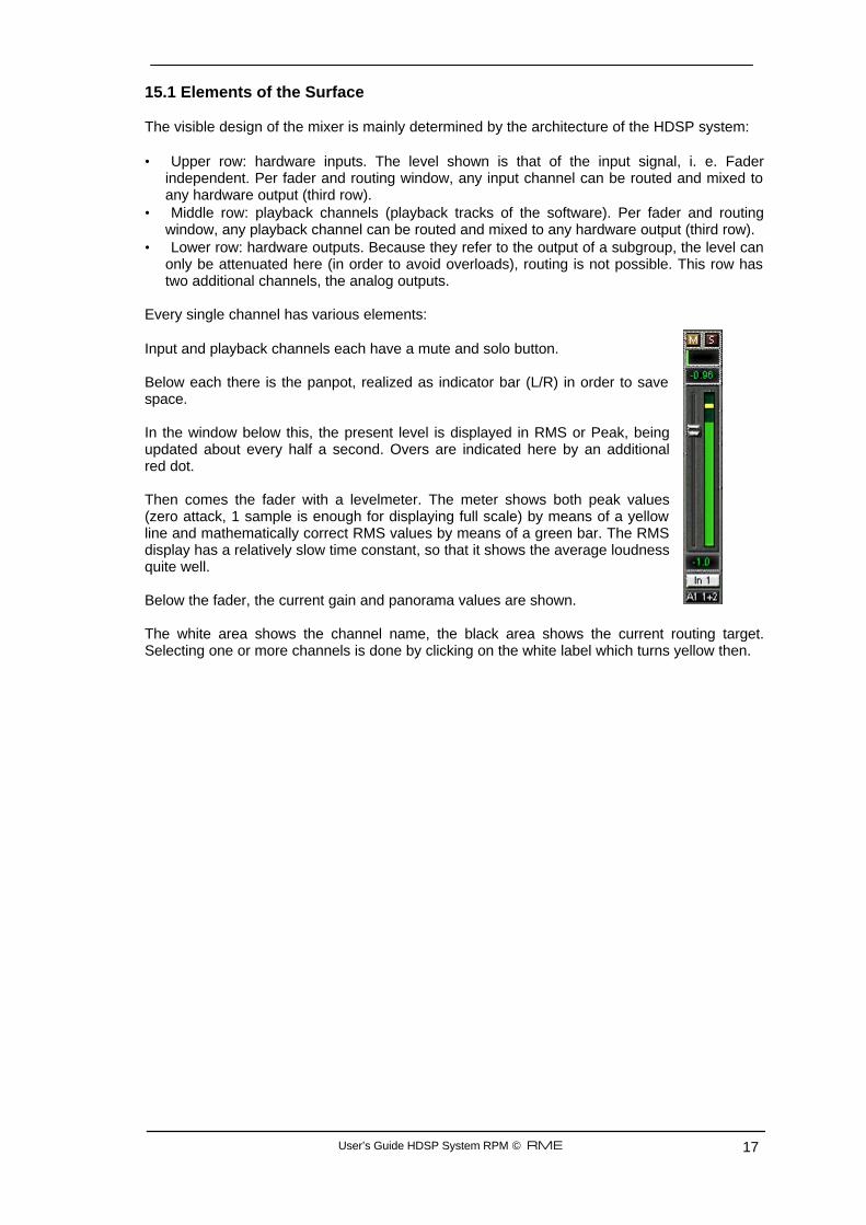
Every single channel has various elements: Input and playback channels each have a mute and solo button. Below each there is the panpot, realized as indicator bar (L/R) in order to save space. In the window below this, the present level is displayed in RMS or Peak, being updated about every half a second. Overs are indicated here by an additional red dot. Then comes the fader with a levelmeter. The meter shows both peak values (zero attack, 1 sample is enough for displaying full scale) by means of a yellow line and mathematically correct RMS values by means of a green bar. The RMS display has a relatively slow time constant, so that it shows the average loudness quite well. Below the fader, the current gain and panorama values are shown. The white area shows the channel name, the black area shows the current routing target. Selecting one or more channels is done by clicking on the white label which turns yellow then.
User’s Guide HDSP System RPM © RME 18
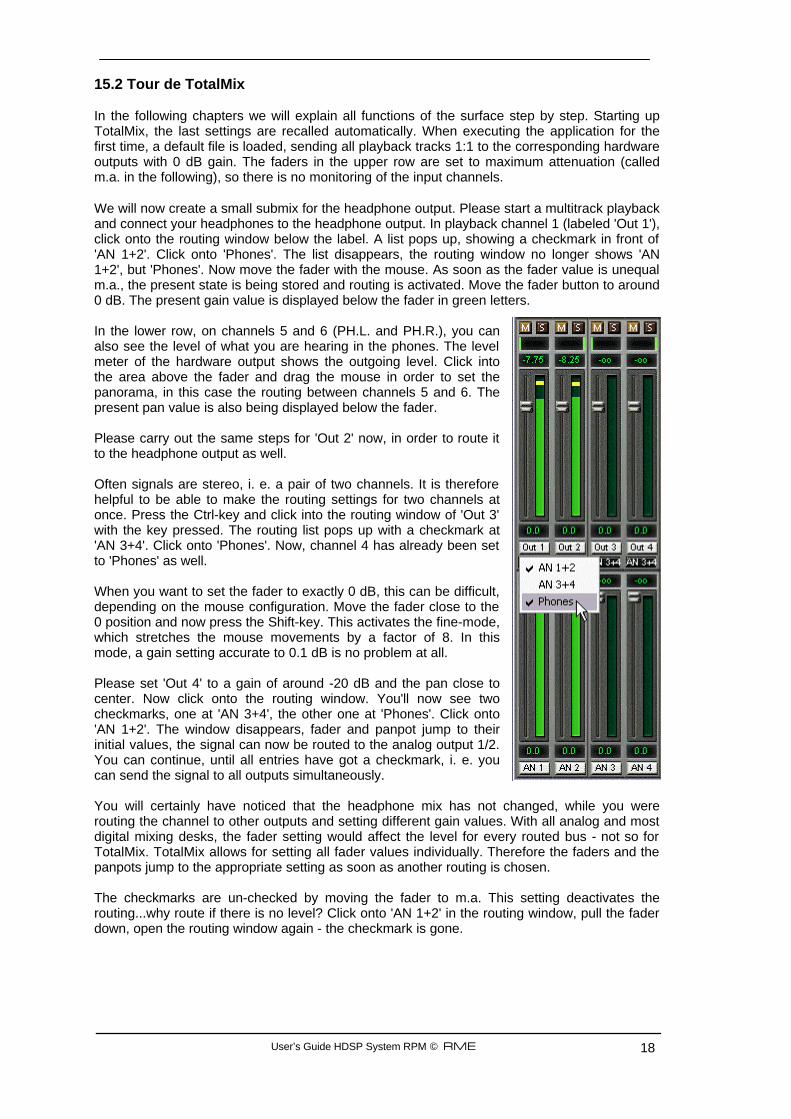
15.2 Tour de TotalMix In the following chapters we will explain all functions of the surface step by step. Starting up TotalMix, the last settings are recalled automatically. When executing the application for the first time, a default file is loaded, sending all playback tracks 1:1 to the corresponding hardware outputs with 0 dB gain. The faders in the upper row are set to maximum attenuation (called m.a. in the following), so there is no monitoring of the input channels. We will now create a small submix for the headphone output. Please start a multitrack playback and connect your headphones to the headphone output. In playback channel 1 (labeled 'Out 1'), click onto the routing window below the label. A list pops up, showing a checkmark in front of 'AN 1+2'. Click onto 'Phones'. The list disappears, the routing window no longer shows 'AN 1+2', but 'Phones'. Now move the fader with the mouse. As soon as the fader value is unequal m.a., the present state is being stored and routing is activated. Move the fader button to around 0 dB. The present gain value is displayed below the fader in green letters. In the lower row, on channels 5 and 6 (PH.L. and PH.R.), you can also see the level of what you are hearing in the phones. The level meter of the hardware output shows the outgoing level. Click into the area above the fader and drag the mouse in order to set the panorama, in this case the routing between channels 5 and 6. The present pan value is also being displayed below the fader. Please carry out the same steps for 'Out 2' now, in order to route it to the headphone output as well. Often signals are stereo, i. e. a pair of two channels. It is therefore helpful to be able to make the routing settings for two channels at once. Press the Ctrl-key and click into the routing window of 'Out 3' with the key pressed. The routing list pops up with a checkmark at 'AN 3+4'. Click onto 'Phones'. Now, channel 4 has already been set to 'Phones' as well. When you want to set the fader to exactly 0 dB, this can be difficult, depending on the mouse configuration. Move the fader close to the 0 position and now press the Shift-key. This activates the fine-mode, which stretches the mouse movements by a factor of 8. In this mode, a gain setting accurate to 0.1 dB is no problem at all. Please set 'Out 4' to a gain of around -20 dB and the pan close to center. Now click onto the routing window. You'll now see two checkmarks, one at 'AN 3+4', the other one at 'Phones'. Click onto 'AN 1+2'. The window disappears, fader and panpot jump to their initial values, the signal can now be routed to the analog output 1/2. You can continue, until all entries have got a checkmark, i. e. you can send the signal to all outputs simultaneously. You will certainly have noticed that the headphone mix has not changed, while you were routing the channel to other outputs and setting different gain values. With all analog and most digital mixing desks, the fader setting would affect the level for every routed bus - not so for TotalMix. TotalMix allows for setting all fader values individually. Therefore the faders and the panpots jump to the appropriate setting as soon as another routing is chosen. The checkmarks are un-checked by moving the fader to m.a. This setting deactivates the routing...why route if there is no level? Click onto 'AN 1+2' in the routing window, pull the fader down, open the routing window again - the checkmark is gone.
User’s Guide HDSP System RPM © RME 19
15.3 Submix View Such a wide range of possibilities make it difficult to maintain the overview. Because practically all hardware outputs can be used for different submixes, as shown (up to 9 completely independent stereo submixes, 4 4-channel submixes etc.). And when opening the routing windows you might see an army of checkmarks, but you don't get an overwiev, i.e., how the signals come together and where. This problem is removed by the view mode 'Submix'. In this mode, all routing windows jump to the routing pair just being selected. So you can then see immediately, which channels, which fader and pan settings make a submix (for example 'Phones'). At the same time the Submix View simplifies setting up the mixer, as all channels can be set simultaneously to the same routing destination with just one click. 15.4 Mute and Solo Mute works pre-fader, thus mutes all active routings of the channel. As soon as any Mute button is pressed, the Master Mute button lights up in the quick access area. It can switch all selected mutes off and on again. You can comfortably make mute groups to activate and deactivate this way. The same holds true for the Solo and the Master Solo buttons. Solo is working as a solo-in-place. As soon as one Solo button is pressed, all other Mute buttons are activated and light up. 15.5 Hotkeys TotalMix knows only a few, but very effective key combinations, that make setting the mixer up considerably easier and faster. The Shift-key for the fine-mode for faders and panpots has already been mentioned. But the Ctrl-key can do far more than changing the routing pairwise: • Clicking anywhere into the fader area with the Ctrl-key pressed, sets the fader to 0 dB, -6
dB for the hardware outputs. • Clicking anywhere into the pan area with the Ctrl-key pressed, sets the panorama to <C>
meaning 'Center'. • Clicking a Preset button while holding down Ctrl, the original (factory) preset will be loaded. • Using Ctrl and any number between 1 and 8 (not on the numeric keypad!) will load the
corresponding factory default preset • Clicking the Card 2 button while holding down Ctrl opens a second TotalMix window. The faders can also be moved pairwise, corresponding to the stereo-routing settings. This can be achieved by pressing the Alt-key and is especially comfortable when setting the SPDIF and analog output level. Even the Panoramas can be operated with Alt, from stereo through mono to inversed channels. But also the Mute and Solo buttons (ganged or inversed switching!). At the same time, TotalMix also supports combinations of these keys. If you press Ctrl and Alt at the same time, clicking with the mouse makes the faders jump to 0 dB pairwise, and they can be set pairwise by Shift-Alt in fine-mode. Also very useful: the faders have two mouse areas. The first area is the fader button, which can be grabbed at any place without changing the position. This avoids unwanted changes when clicking onto it. The second area is the whole fader setting area. Clicking into this area makes the fader jump to the mouse at once. If you want to set several faders to m.a. for instance, it is sufficient to click onto the lower end of the fader path. Which happens pairwise with the Alt-key pressed.
User’s Guide HDSP System RPM © RME 20
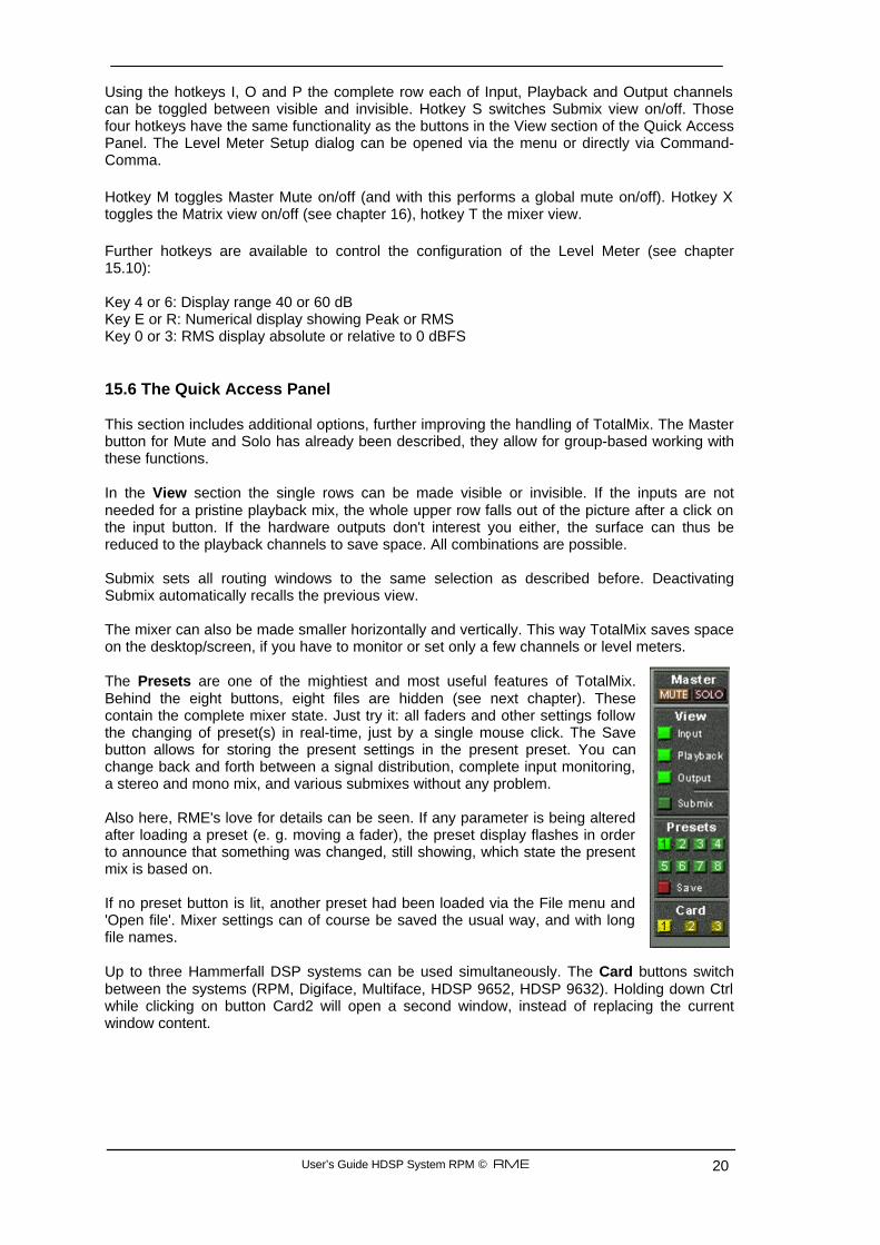
Using the hotkeys I, O and P the complete row each of Input, Playback and Output channels can be toggled between visible and invisible. Hotkey S switches Submix view on/off. Those four hotkeys have the same functionality as the buttons in the View section of the Quick Access Panel. The Level Meter Setup dialog can be opened via the menu or directly via Command-Comma. Hotkey M toggles Master Mute on/off (and with this performs a global mute on/off). Hotkey X toggles the Matrix view on/off (see chapter 16), hotkey T the mixer view. Further hotkeys are available to control the configuration of the Level Meter (see chapter 15.10): Key 4 or 6: Display range 40 or 60 dB Key E or R: Numerical display showing Peak or RMS Key 0 or 3: RMS display absolute or relative to 0 dBFS 15.6 The Quick Access Panel This section includes additional options, further improving the handling of TotalMix. The Master button for Mute and Solo has already been described, they allow for group-based working with these functions. In the View section the single rows can be made visible or invisible. If the inputs are not needed for a pristine playback mix, the whole upper row falls out of the picture after a click on the input button. If the hardware outputs don't interest you either, the surface can thus be reduced to the playback channels to save space. All combinations are possible. Submix sets all routing windows to the same selection as described before. Deactivating Submix automatically recalls the previous view. The mixer can also be made smaller horizontally and vertically. This way TotalMix saves space on the desktop/screen, if you have to monitor or set only a few channels or level meters. The Presets are one of the mightiest and most useful features of TotalMix. Behind the eight buttons, eight files are hidden (see next chapter). These contain the complete mixer state. Just try it: all faders and other settings follow the changing of preset(s) in real-time, just by a single mouse click. The Save button allows for storing the present settings in the present preset. You can change back and forth between a signal distribution, complete input monitoring, a stereo and mono mix, and various submixes without any problem. Also here, RME's love for details can be seen. If any parameter is being altered after loading a preset (e. g. moving a fader), the preset display flashes in order to announce that something was changed, still showing, which state the present mix is based on. If no preset button is lit, another preset had been loaded via the File menu and 'Open file'. Mixer settings can of course be saved the usual way, and with long file names. Up to three Hammerfall DSP systems can be used simultaneously. The Card buttons switch between the systems (RPM, Digiface, Multiface, HDSP 9652, HDSP 9632). Holding down Ctrl while clicking on button Card2 will open a second window, instead of replacing the current window content.
User’s Guide HDSP System RPM © RME 21
15.7 Presets TotalMix includes 8 factory presets, stored within the program. But the presets can be changed at any time, because TotalMix stores and reads the changed presets from the files preset11.mix to preset81.mix. These files are found in the folder User, <Username>, Library / Preferences / Hammerfall DSP. The first number indicates the current preset, the second number the current card/system. This method offers two major advantages: • Presets modified by the user will not be overwritten when reinstalling or updating the driver • The factory presets remain unchanged, and can be reloaded anytime. The original factory preset can be reloaded by holding down the Ctrl-key and clicking on any preset button. Alternatively the files described above can be renamed, moved to a different directory, or being deleted. The 8 factory presets offer not only a useful functionality for TotalMix, but also a pretty good base to modify them to your personal needs. Preset1.mix Description: All channels routed 1:1, playback monitoring via headphone out Details: All inputs maximum attenuation (m.a.). All playback channels 0 dB, routet to the same output. All output channels 0 dB, Phones -6 dB and linked. Submix of all inputs and outputs to the Phones output, with input faders set to m.a., playback to 0 dB. All channels prepared for all routings to left/right panning, Mic center panning. Level display set to RMS +3 dB. Note: This preset is Default, offering the standard functionality of a I/O-card. Preset2.mix Description: All channels routed 1:1, input and playback monitoring via Phones. As Preset 1, plus submix of all inputs (0 dB) on Phones. Preset3.mix Description: All channels 1:1, input and playback monitoring via Phones and outputs. As Preset 2, but all inputs set to 0 dB (1:1 pass through). Preset4.mix Description: All channels 1:1, playback monitoring via Phones and outputs. As Preset 3, but all inputs muted. Note: This preset is default for ZLM and MME Mix/Replace monitoring. The factory preset 4 will also be loaded by a click on Load Def. Preset5.mix Description: All faders m.a. As Preset 1, but all Inputs/Playbacks m.a. Preset6.mix Description: Submix on AN 1+2. As Preset 1, plus submix of all Playbacks on AN 1+2. View Submix AN 1+2 active. Preset7.mix Description: Submix on AN 1+2. As Preset 6, but all inputs set to 0 dB (1:1 pass through). View Submix AN 1+2 active. Preset8.mix Description: Panic. As Preset 4, but also playback muted (no output signal)
User’s Guide HDSP System RPM © RME 22
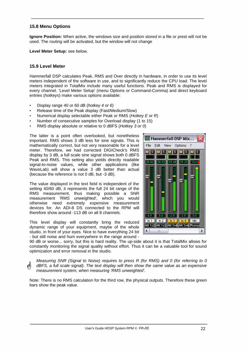
15.8 Menu Options Ignore Position: When active, the windows size and position stored in a file or prest will not be used. The routing will be activated, but the window will not change Level Meter Setup: see below. 15.9 Level Meter Hammerfall DSP calculates Peak, RMS and Over directly in hardware, in order to use its level meters independent of the software in use, and to significantly reduce the CPU load. The level meters integrated in TotalMix include many useful functions. Peak and RMS is displayed for every channel. 'Level Meter Setup' (menu Options or Command-Comma) and direct keyboard entries (hotkeys) make various options available: • Display range 40 or 60 dB (hotkey 4 or 6) • Release time of the Peak display (Fast/Medium/Slow) • Numerical display selectable either Peak or RMS (Hotkey E or R) • Number of consecutive samples for Overload display (1 to 15) • RMS display absolute or relative to 0 dBFS (Hotkey 3 or 0) The latter is a point often overlooked, but nonetheless important. RMS shows 3 dB less for sine signals. This is mathematically correct, but not very reasonable for a level meter. Therefore, we had corrected DIGICheck's RMS display by 3 dB, a full scale sine signal shows both 0 dBFS Peak and RMS. This setting also yields directly readable signal-to-noise values, while other applications (like WaveLab) will show a value 3 dB better than actual (because the reference is not 0 dB, but -3 dB). The value displayed in the text field is independent of the setting 40/60 dB, it represents the full 24 bit range of the RMS measurement, thus making possible a SNR measurement 'RMS unweighted', which you would otherwise need extremely expensive measurement devices for. An ADI-8 DS connected to the RPM will therefore show around -113 dB on all 8 channels. This level display will constantly bring the reduced dynamic range of your equipment, maybe of the whole studio, in front of your eyes. Nice to have everything 24 bit - but still noise and hum everywhere in the range around -90 dB or worse... sorry, but this is hard reality. The up-side about it is that TotalMix allows for constantly monitoring the signal quality without effort. Thus it can be a valuable tool for sound optimization and error removal in the studio.
Measuring SNR (Signal to Noise) requires to press R (for RMS) and 0 (for referring to 0 dBFS, a full scale signal). The text display will then show the same value as an expensive measurement system, when measuring ‘RMS unweighted’.
Note: There is no RMS calculation for the third row, the physical outputs. Therefore these green bars show the peak value.
User’s Guide HDSP System RPM © RME 23
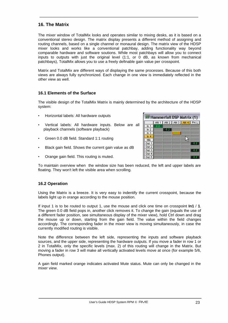
16. The Matrix The mixer window of TotalMix looks and operates similar to mixing desks, as it is based on a conventional stereo design. The matrix display presents a different method of assigning and routing channels, based on a single channel or monaural design. The matrix view of the HDSP mixer looks and works like a conventional patchbay, adding functionality way beyond comparable hardware and software soutions. While most patchbays will allow you to connect inputs to outputs with just the original level (1:1, or 0 dB, as known from mechanical patchbays), TotalMix allows you to use a freely definable gain value per crosspoint. Matrix and TotalMix are different ways of displaying the same processes. Because of this both views are always fully synchronized. Each change in one view is immediately reflected in the other view as well. 16.1 Elements of the Surface The visible design of the TotalMix Matrix is mainly determined by the architecture of the HDSP system: • Horizontal labels: All hardware outputs • Vertical labels: All hardware inputs. Below are all
playback channels (software playback) • Green 0.0 dB field. Standard 1:1 routing • Black gain field. Shows the current gain value as dB • Orange gain field. This routing is muted. To maintain overview when the window size has been reduced, the left and upper labels are floating. They won't left the visible area when scrolling. 16.2 Operation Using the Matrix is a breeze. It is very easy to indentify the current crosspoint, because the labels light up in orange according to the mouse position. If input 1 is to be routed to output 1, use the mouse and click one time on crosspoint In1 / 1. The green 0.0 dB field pops in, another click removes it. To change the gain (equals the use of a different fader position, see simultaneous display of the mixer view), hold Ctrl down and drag the mouse up or down, starting from the gain field. The value within the field changes accordingly. The corresponding fader in the mixer view is moving simultaneously, in case the currently modified routing is visible. Note the difference between the left side, representing the inputs and software playback sources, and the upper side, representing the hardware outputs. If you move a fader in row 1 or 2 in TotalMix, only the specific levels (max. 2) of this routing will change in the Matrix. But moving a fader in row 3 will make all vertically activated levels move at once (for example 5/6, Phones output). A gain field marked orange indicates activated Mute status. Mute can only be changed in the mixer view.
User’s Guide HDSP System RPM © RME 24
16.3 Advantages of the Matrix The Matrix not always replaces the mixer view, but it significantly enhances the routing capabilities and - more important - is a brilliant way to get a fast overview on all active routings. It shows you in a glance what's going on. And since the Matrix operates monaural, it is very easy to set up specific routings with specific gains. Example 1: You want TotalMix to route all software outputs to all corresponding hardware outputs, and have a submix of all inputs and software outputs on the analog output (equals factory preset 2). Setting up such a submix is easy. But how to check at a later time, that all settings are still exactly the way you wanted them to be? So far the only way to check that TotalMix is correctly set up this way, is to activate Submix view, step through all existing software outputs, and have a very concentrated look at the faders and displayed levels of each routing. That doesn't sound comfortably nor error-free, right? Here is where the Matrix shines. In the Matrix view, you simply see a line from upper left to lower right, all fields marked as unity gain. Plus two rows vertically all at the same level setting. You just need 2 seconds to be sure no unwanted routing is active anywhere, and that all levels match precisely! Example 2: The Matrix allows you to set up routings which would be nearly impossible to achieve by fiddling around with level and pan. Let's say you want to send input 1 to output 1 at 0 dB, to output 2 at -3 dB, to output 3 at -6 dB and to output 4 at -9 dB. Each time you set up the right channel (2/4), the change in pan destroys the gain setting of the left channel (1/2). A real hassle! In Matrix view, you simply click on the corresponding routing point, set the level via Ctrl-mouse, and move on. You can see in the desk view how level and pan changes automatically when performing the second (fourth...) setting. 17. TotalMix Super-Features 17.1 Selection and Group-based Operation Click on the white name label of channel 1 and 2 in TotalMix. Be sure to have channel 3's fader set to a different position and click on its label too. All three labels have changed to the colour orange, which means they are selected. Now moving any of these faders will make the other faders move too. This is called 'building a group of faders', or ganging faders, maintaining their relative position. Building groups or ganging can be done in any row, but is limited to operate horizontally within one row. If you usually don't need this, you can at least gang the analog outputs. The advantage over holding the Alt-key is that Alt sets both channels to the same level (can be handy too), while grouping via selection will retain any offset (if you need one channel to be louder all the time etc.). Note: if you move the mouse so that any channel reaches upper or lower maximum position, and release the mouse button, the relative position is lost. Tip: gang some submixes and watch all routing levels change like crazy in the Matrix view.
User’s Guide HDSP System RPM © RME 25
17.2 Copy Routings to other Channels TotalMix allows to copy complete routing schemes of inputs and outputs. Example 1: You have input 4 (guitar) routed within several submixes/hardware outputs (= headphones). Now you'll get another input with keyboards that should appear in the same way on all headphones. Select input 4, open the menu Edit. It shows 'Copy In 4'. Now select the desired new input, for example In 1. The menu now shows 'Paste In 4 to In 1'. Click on it - done. If you are familiar with this functionality just use Ctrl-C and Ctrl-V. Else the self updating menu will always let you know what actually will happen. Tip: have the Matrix view open when doing this. It will show the new routings immediately, so copying is easier to understand and to follow. Example 2: You have built a comprehensive submix on outputs 1/2, but now need the exact same signal also on the outputs 3/4. Click on Out 1, Ctrl-C, click on Out 3, Ctrl-V, same with 2/4 - you're done! The Matrix shows you the difference between both examples. Example 1 means copying lines (horizontally), while example 2 means copying rows (vertically). Example 3: Let's say the guitarist finished his recording, and you now need the same signal again on all headphones, but this time it comes from the recording software (playback row). No problem, you can even copy between rows 1 and 2 (copying between row 3 and 1/2 isn't possible). But how to select while a group is active? De-selecting the group first? Not necessary! TotalMix always updates the copy and paste process with the last selection. This way you don't have to de-activate any group-selections when desiring to perform a copy and paste action. 17.3 Delete Routings The fastest way to delete complex routings: select a channel in the mixer view, click on the menu entry Edit and select Delete. Or simply hit the Del-key. Attention: there is no undo in TotalMix, so be careful with this function!
User’s Guide HDSP System RPM © RME 26
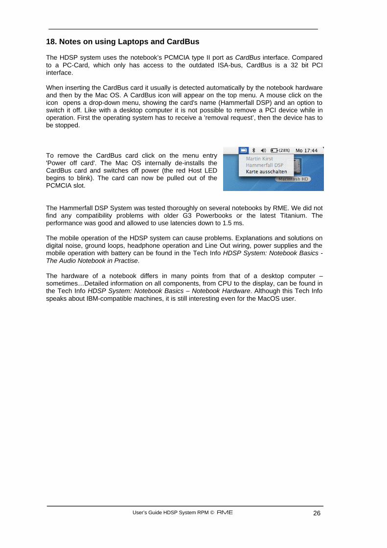
18. Notes on using Laptops and CardBus The HDSP system uses the notebook’s PCMCIA type II port as CardBus interface. Compared to a PC-Card, which only has access to the outdated ISA-bus, CardBus is a 32 bit PCI interface. When inserting the CardBus card it usually is detected automatically by the notebook hardware and then by the Mac OS. A CardBus icon will appear on the top menu. A mouse click on the icon opens a drop-down menu, showing the card's name (Hammerfall DSP) and an option to switch it off. Like with a desktop computer it is not possible to remove a PCI device while in operation. First the operating system has to receive a 'removal request’, then the device has to be stopped. To remove the CardBus card click on the menu entry 'Power off card'. The Mac OS internally de-installs the CardBus card and switches off power (the red Host LED begins to blink). The card can now be pulled out of the PCMCIA slot. The Hammerfall DSP System was tested thoroughly on several notebooks by RME. We did not find any compatibility problems with older G3 Powerbooks or the latest Titanium. The performance was good and allowed to use latencies down to 1.5 ms. The mobile operation of the HDSP system can cause problems. Explanations and solutions on digital noise, ground loops, headphone operation and Line Out wiring, power supplies and the mobile operation with battery can be found in the Tech Info HDSP System: Notebook Basics - The Audio Notebook in Practise. The hardware of a notebook differs in many points from that of a desktop computer – sometimes…Detailed information on all components, from CPU to the display, can be found in the Tech Info HDSP System: Notebook Basics – Notebook Hardware. Although this Tech Info speaks about IBM-compatible machines, it is still interesting even for the MacOS user.
User’s Guide HDSP System RPM © RME 27
19. Hotline - Troubleshooting The newest information can always be found on our website www.rme-audio.com, section Support, Macintosh OS. Playback works, but record doesn’t: • Check that there is a valid signal at the input. • Check whether the Hammerfall DSP has been selected as recording device in the audio
application. Crackle during record or playback: • Increase the number and size of buffers in the application. • Try different cables to rule out any defects here. The card and drivers have been installed correctly, but playback does not work: • Is Hammerfall DSP listed in the System Profiler/PCI? (Vendor 10EE, Device ID 3FC5). • Has Hammerfall DSP been selected as current playback device in the audio application? 21. Accessories RME offers several optional components, further increasing the flexibility and usability of the HDSP system. Additionally parts of the HDSP system, like the special CardBus cable and the switching power supply, are available seperately. Part Number Description 36000 19“, 1UH Universal rack holder This 19" rack holder has holes for Digiface and RPM. Two units can be installed side by side in any combination. The rack holder also includes holes for nearly all 19" half-rack units from other manufacturers. 36001 Firewire cable IEE1394 6M/6M, 1 m (3.3 ft) 36002 Firewire cable IEE1394 6M/6M, 3 m (9.9 ft) 36005 Firewire cable IEE1394 6M/6M, 5 m (16.4 ft) 36010 Firewire cable IEE1394 6M/6M, 10 m (32.8 ft) Firewire cable for the HDSP system, both sides 6-pin male. Cable longer than 16 ft is not allowed for Firewire, therfore hard to get in computer shops. However the HDSP system can operates flawlessly even with a cable length of up to 50ft (15 m). 36081 RME Firewire cable for CardBus 15/6M, 5 m (16.4 ft) 36082 RME Firewire cable for CardBus 15/6M, 1 m (3.3 ft) Special cable 15-pin close Lan coded to 6-pin male, for RME CardBus card. 37011 Power supply for HDSP CardBus card Robust and light weigth switching power supply, 100V-240V AC, 12V 1.25 A DC.
User’s Guide HDSP System RPM © RME 28
22. TECH INFO Not all information to and around our products fit in a manual. Therefore RME offers a lot more and detailed information in the Tech Infos. The very latest Tech Infos can be found on our website, section News & Infos, or the directory \rmeaudio.web\techinfo on the RME Driver CD. These are some of the currently available Tech Infos: Synchronization II (DIGI96 series) Digital audio synchronization - technical background and pitfalls. Installation problems Problem descriptions and solutions. Information on driver updates Lists all changes in the drivers. Configuring Logic, Samplitude, Cubase, Cakewalk, Sonar and SAWPlus32 Step by step instructions for use with RME cards. DIGICheck: Analysis, tests and measurements with the DIGI96 series A description of DIGICheck, including technical basics. ADI-8 Inside Technical information about the RME ADI-8 (24-bit AD/DA converter). HDSP System: Notebook Basics - Notebook Hardware HDSP System: Notebook Basics - The Audio Notebook in Practice HDSP System: Notebook Basics - Background Knowledge and Tuning HDSP System: Notebook Tests - Compatibility and Performance Many background information on and tests of notebooks HDSP System: TotalMix - Hardware and Technology HDSP System: TotalMix - Software, features, operation The digital mixer of the Hammerfall DSP in theory and practise
User’s Guide HDSP System RPM © RME 29
23. Warranty Each individual Hammerfall DSP undergoes comprehensive quality control and a complete test in a PC environment at RME before shipping. This may cause very slight signs of wear (if it looks like it was used one time before - it was). The usage of high grade components allows us to offer a full two year warranty. We accept a copy of the sales receipt as valid warranty legitimation. RME’s replacement service within this period is handled by the retailer. If you suspect that your card is faulty, please contact your local retailer. The warranty does not cover damage caused by improper installation or maltreatment - replacement or repair in such cases can only be carried out at the owner’s expense. RME does not accept claims for damages of any kind, especially consequential damage. Liability is limited to the value of the Hammerfall DSP. The general terms of business drawn up by Synthax Audio AG apply at all times. 24. Appendix RME news, driver updates and further product information are available on our website: http://www.rme-audio.com If you prefer to read the information off-line, you can load a complete copy of the RME website from the RME Driver CD (in the \rmeaudio.web directory) into your browser. Trademarks All trademarks, registered or otherwise, are the property of their respective owners. RME, DIGI96, SyncAlign, SynCheck, ZLM and Hammerfall are registered trademarks of RME Intelligent Audio Solutions. DIGICheck, TotalMix, Intelligent Clock Control and TMS are trademarks of RME Intelligent Audio Solutions. Microsoft, Windows, Windows 98/2000/XP are registered trademarks or trademarks of Microsoft Corp. Apple and Mac OS are registered trademarks of Apple Computer Inc. Steinberg, Cubase and VST are registered trademarks of Steinberg Media Technologies GmbH. ASIO is a trademark of Steinberg Media Technologies GmbH. Copyright Matthias Carstens, 4/2004. Version 1.0 Current driver version: Mac OS X 1.5b Although the contents of this User’s Guide have been thoroughly checked for errors, RME can not guarantee that it is correct throughout. RME does not accept responsibility for any misleading or incorrect information within this guide. Lending or copying any part of the guide or the RME Driver CD, or any commercial exploitation of these media without express written permission from RME Intelligent Audio Solutions is prohibited. RME reserves the right to change specifications at any time without notice.
User’s Guide HDSP System RPM © RME 30
25. Block Diagram RPM
User’s Guide HDSP System RPM © RME 31
26. CE and FCC Compliance Statements CE This device has been tested and found to comply with the EN55022 class B and EN50082-1 norms for digital devices, according to the European Council directive on counterpart laws in the member states relating to electromagnetic compatibility (EMVG). FCC This device has been tested and found to comply with the requirements listed in FCC Regulations, part 15 for Class ‘B’ digital devices. Compliance with these requirements provides a reasonable level of assurance that your use of this product in a residential environment will not result in harmful interference with other electronic devices. This equipment generates radio frequencies and, if not installed and used according to the instructions in the User’s Guide may cause interference harmful to the operation of other electronic devices. Compliance with FCC regulations does not guarantee that interference will not occur in all installations. If this product is found to be the source of interference, which can be determined by turning the unit off and on again, please try to eliminate the problem by using one of the following measures: • Relocate either this product or the device that is being affected by the interference • Use power outlets on different branch circuits, or install AC line filters • Contact your local retailer or any qualified radio and television engineer When connecting external devices to this product, compliance to limits for a Class ‘B’ device requires the use of shielded cables. FCC compliance statement: Tested to comply with FCC standards for home or office use.


![User’s Manual - OKI · Unless otherwise specified, this manual uses screenshots of the following screens. • For Windows: Windows 7 • For Mac OS X: Mac OS X 10.9 [OKI Printer]](https://img.pdfslide.us/doc/110x75/5f0b78907e708231d430ae1a/useras-manual-oki-unless-otherwise-specified-this-manual-uses-screenshots-of.jpg)