Embed Size (px)
Citation preview

User’s Guide
Digital Wireless Triax camera system v1For SD cameras
3922 496 30051version 9

Declaration of Conformity
We, Grass Valley Nederland B.V., Kapittelweg 10, 4827 HG Breda, The Netherlands, declare under our sole responsibility that the LDK 5450,LDK 5451, LDK 4450, LDK 4452, LDK4453 and LDK4454 is in compliance with the following standards:
EN60950 : SafetyEN301489-3 : EMC for Radio DevicesETS 300 220 : RadioETS 300 440 : Radio
following the provisions of:RTT&E Directive 1999/5/CE
We, Grass Valley Nederland B.V., Kapittelweg 10, 4827 HG Breda, The Netherlands, declare under our sole responsibility that the remainderof the equipment used in this product is in compliance with the following standards:
EN60065 : SafetyEN55103-1 : EMC (Emission)EN55103-2 : EMC (Immunity)
following the provisions of:a. the Safety Directives 73/23//EEC and 93/68/EECb. the EMC Directives 89/336/EEC and 93/68/EEC
© Grass Valley Nederland B.V. 2005
Für diese Unterlage behalten wir uns alleRechte vor (Gemäß DIN 34). TechnischeÄnderungen im Zuge derWeiterentwicklung vorbehalten.
Copyright
Toute communication ou reproduction de cedocument, toute exploitation oucommunication de son contenu sontinterdites, sauf autorisation expresse. Toutman-quement à cette règle est illicite etexpose son auteur au versement dedommages et intérêts. Tous nos droits sontréservés pour le cas de la délivrance d'unmodèle d'utilité. Sous réserve demodification au cours de l'évolutiontechnique.
Copying of this document and giving it toothers, and the use or communication ofthe contents thereof, are forbidden withoutexpress authority. Offenders are liable tothe payment of damages. All rights arereserved in the event of the grant of apatent or the registration of a utility modelor design. Liable to technical alterations inthe course of further development.

version 9 User’s Guide - Digital Wireless System 3
User’s Guide
Digital Wireless Triax Camera System
Contents
Safety Summary ........................................................... 4Cautions and Warnings ............................................... 4Cathode ray tubes ....................................................... 5Sicherheit (Zusammenfassung) .................................... 6Warn- und Gefahrenhinweise ..................................... 6Elektronenstrahlröhren ............................................... 7
Technology ...................................................................... 8
Features .......................................................................... 8
Configuration .................................................................. 9
Setting up the camera adapter ................................... 10Wireless camera adapter ............................................ 10Exchanging the Video Frequency Module .................. 10Exchanging the RF Data Module ................................ 11Attaching the adapter to the camera ......................... 12Attaching antennas to the adapter ............................ 13Camera power supply ................................................ 14Viewfinder battery indicator ...................................... 14Menu setup ............................................................... 14Selecting the video frequency channel ....................... 14Selecting the data frequency channel ........................ 14Selecting the camera number .................................... 14Frequency table for Video modules: ........................... 15Frequency table for Data modules: ............................ 15
AMU indicators ............................................................. 18
Setting up the AMU ..................................................... 19AMU and antenna positioning .................................. 19AMU identification number ....................................... 20Video frequency selection .......................................... 20Data frequency selection ........................................... 20
WCU Controls and indicators ....................................... 22
WCU Controls.. .............................................................. 23
Setting up the WCU ..................................................... 23WCU connections ...................................................... 23Set the video frequency channel ................................ 23Set the data frequency channel ................................. 23Set the camera number ............................................. 23WCU menu settings .................................................. 24Signalling inputs ....................................................... 24
Audio ............................................................................. 25Audio settings ........................................................... 25
Intercom ........................................................................ 26Camera menu setup .................................................. 26Rear controls ............................................................. 26Intercom settings on WCU ........................................ 26
WCA connectors ........................................................... 27
AMU Connectors ........................................................... 30
WCU Connectors ........................................................... 32
Specifications ................................................................ 39Wireless adapter unit ................................................ 39RF receiver units ......................................................... 40RF data emitter unit ................................................... 40Antenna management unit (AMU) ............................ 41Wireless control unit (WCU)....................................... 41
Type numbers ............................................................... 42Accessories ................................................................ 42
Type numbers ............................................................... 43
4 User’s Guide - Digital Wireless System version 9
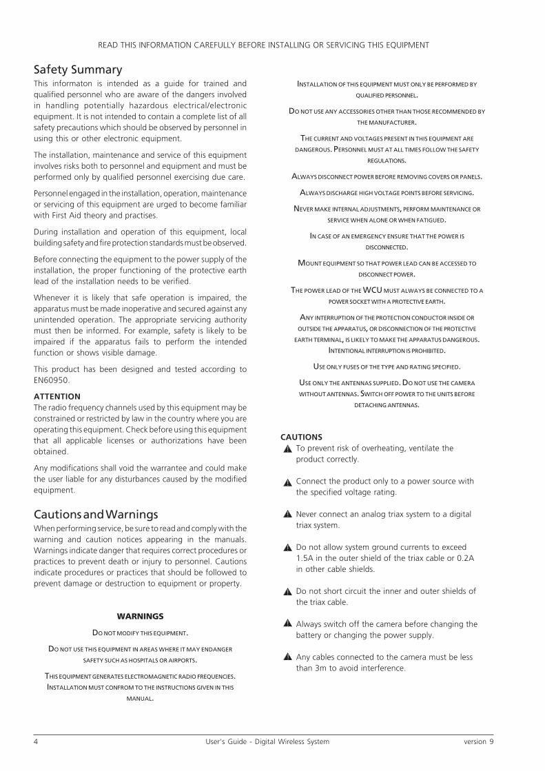
Safety SummaryThis informaton is intended as a guide for trained andqualified personnel who are aware of the dangers involvedin handling potentially hazardous electrical/electronicequipment. It is not intended to contain a complete list of allsafety precautions which should be observed by personnel inusing this or other electronic equipment.
The installation, maintenance and service of this equipmentinvolves risks both to personnel and equipment and must beperformed only by qualified personnel exercising due care.
Personnel engaged in the installation, operation, maintenanceor servicing of this equipment are urged to become familiarwith First Aid theory and practises.
During installation and operation of this equipment, localbuilding safety and fire protection standards must be observed.
Before connecting the equipment to the power supply of theinstallation, the proper functioning of the protective earthlead of the installation needs to be verified.
Whenever it is likely that safe operation is impaired, theapparatus must be made inoperative and secured against anyunintended operation. The appropriate servicing authoritymust then be informed. For example, safety is likely to beimpaired if the apparatus fails to perform the intendedfunction or shows visible damage.
This product has been designed and tested according toEN60950.
ATTENTIONThe radio frequency channels used by this equipment may beconstrained or restricted by law in the country where you areoperating this equipment. Check before using this equipmentthat all applicable licenses or authorizations have beenobtained.
Any modifications shall void the warrantee and could makethe user liable for any disturbances caused by the modifiedequipment.
Cautions and WarningsWhen performing service, be sure to read and comply with thewarning and caution notices appearing in the manuals.Warnings indicate danger that requires correct procedures orpractices to prevent death or injury to personnel. Cautionsindicate procedures or practices that should be followed toprevent damage or destruction to equipment or property.
WARNINGS
DO NOT MODIFY THIS EQUIPMENT.
DO NOT USE THIS EQUIPMENT IN AREAS WHERE IT MAY ENDANGER
SAFETY SUCH AS HOSPITALS OR AIRPORTS.
THIS EQUIPMENT GENERATES ELECTROMAGNETIC RADIO FREQUENCIES.INSTALLATION MUST CONFROM TO THE INSTRUCTIONS GIVEN IN THIS
MANUAL.
READ THIS INFORMATION CAREFULLY BEFORE INSTALLING OR SERVICING THIS EQUIPMENT
INSTALLATION OF THIS EQUIPMENT MUST ONLY BE PERFORMED BY
QUALIFIED PERSONNEL.
DO NOT USE ANY ACCESSORIES OTHER THAN THOSE RECOMMENDED BY
THE MANUFACTURER.
THE CURRENT AND VOLTAGES PRESENT IN THIS EQUIPMENT ARE
DANGEROUS. PERSONNEL MUST AT ALL TIMES FOLLOW THE SAFETY
REGULATIONS.
ALWAYS DISCONNECT POWER BEFORE REMOVING COVERS OR PANELS.
ALWAYS DISCHARGE HIGH VOLTAGE POINTS BEFORE SERVICING.
NEVER MAKE INTERNAL ADJUSTMENTS, PERFORM MAINTENANCE OR
SERVICE WHEN ALONE OR WHEN FATIGUED.
IN CASE OF AN EMERGENCY ENSURE THAT THE POWER ISDISCONNECTED.
MOUNT EQUIPMENT SO THAT POWER LEAD CAN BE ACCESSED TO
DISCONNECT POWER.
THE POWER LEAD OF THE WCU MUST ALWAYS BE CONNECTED TO APOWER SOCKET WITH A PROTECTIVE EARTH.
ANY INTERRUPTION OF THE PROTECTION CONDUCTOR INSIDE OR
OUTSIDE THE APPARATUS, OR DISCONNECTION OF THE PROTECTIVE
EARTH TERMINAL, IS LIKELY TO MAKE THE APPARATUS DANGEROUS.INTENTIONAL INTERRUPTION IS PROHIBITED.
USE ONLY FUSES OF THE TYPE AND RATING SPECIFIED.
USE ONLY THE ANTENNAS SUPPLIED. DO NOT USE THE CAMERA
WITHOUT ANTENNAS. SWITCH OFF POWER TO THE UNITS BEFORE
DETACHING ANTENNAS.
CAUTIONSTo prevent risk of overheating, ventilate theproduct correctly.
Connect the product only to a power source withthe specified voltage rating.
Never connect an analog triax system to a digitaltriax system.
Do not allow system ground currents to exceed1.5A in the outer shield of the triax cable or 0.2Ain other cable shields.
Do not short circuit the inner and outer shields ofthe triax cable.
Always switch off the camera before changing thebattery or changing the power supply.
Any cables connected to the camera must be lessthan 3m to avoid interference.
!
!
!
!
!
!
!

version 9 User’s Guide - Digital Wireless System 5
Mains Lead Wiring for UK Users
The wires in the mains lead are coloured in accordance withthe following code:
GREEN AND YELLOW - EARTHBLUE - NEUTRALBROWN - LIVE
As the colours of the wires in the mains lead of thisapparatus may not correspond with the coloured markingsidentifying the terminals in your plug proceed as follows:
• The wire coloured GREEN AND YELLOW must beconnected to the terminal on the plug marked withthe letter E or by the safety earth symbol or colouredGREEN or GREEN AND YELLOW.
• The wire coloured BROWN must be connected to theterminal marked with the letter L or coloured RED.
• The wire coloured BLUE must be connected to theterminal marked with the letter N or coloured BLACK.
Ensure that your equipment is connected correctly - if youare in any doubt consult a qualified electrician.
Cathode ray tubesComponents marked on the circuit diagram are criticalfor safety and include those specified to comply with X-rayemission standards for units using cathode ray tubes andthose specified for compliance with various regulationsregarding spurious radiation emission.
When servicing units that use cathode ray tubes (CRTs), thecathode ray tubes themselves, the high voltage circuits andrelated circuits are specifically chosen so that they complywith recognized codes pertaining to X-ray emission.
Consequently, when servicing, replace the cathode raytubes and other parts with specified parts only. Do notattempt to modify these circuits as any unauthorizedmodification can increase the high voltage value and causeX-ray emission from the cathode ray tube. Handle thecathode ray tube only when wearing shatterproof gogglesand after discharging the high voltage completely.
Symbol Colour Explanation
Red High voltage terminal at which avoltage, with respect to an otherterminal, exists or may beadjusted to 1000V or more.
Yellow/Black Live part.
Yellow/Black This marking indicates that theoperator must refer to anexplanation in the InstructionManual, or that a specificcomponent must be replaced bythe component specified in thedocumentation for safetyreasons.
White/Black Protective earth (ground)terminal.
READ THIS INFORMATION CAREFULLY BEFORE INSTALLING OR SERVICING THIS EQUIPMENT
Summary of cautions used in this manual:
Caution
Always disconnect from the power supply beforeopening the adapter.
Connection panel position in the rack shouldensure that the plug and power cord are withineasy reach for switching off purposes.
Be extremely careful with the connectors betweenthe camera head and the adapter. Do not allowthe guide pins to damage the pins of theconnector. Follow these steps in the order given.Tightening the screws in the wrong order couldresult in mechanical damage to the camera.Loosening the screws in the wrong order couldresult in mechanical damage to the camera.
Never supply power to an adapter without firstensuring that the antennas are attached.
Use only the antennas supplied.
Switch off the power to the units beforedetaching the antennas.
The input voltage to the camera must staybetween +11Vdc and +17 Vdc.
Disconnect the power to the WCU beforeopening the AMU.
!
!
!
!
!
!
!
!
6 User’s Guide - Digital Wireless System version 9
Sicherheit (Zusammenfassung)TDiese Informationen sind als Leitfaden für qualifiziertesFachpersonal gedacht, das die Gefahren beim Umgang mitpotenziell gefährlicher elektrischer/elektronischer Ausrüstungkennt. Es handelt sich dabei nicht um eine vollständigeZusammenstellung aller Sicherheitsvorkehrungen, die beimGebrauch dieser oder anderer elektronischer Geräte zubeachten sind.
Die Montage, Wartung und Instandsetzung dieser Ausrüstungist mit Risiken für Personal und Ausrüstung verbunden unddarf nur von qualifiziertem Personal vorgenommen werden,wobei mit der nötigen Sorgfalt vorzugehen ist.
Mit der Montage, Bedienung, Instandhaltung oderInstandsetzung dieser Ausrüstung betrauten Personen wirddringend geraten, sich mit der Theorie und Praxis der ErstenHilfe vertraut zu machen.
Beim Einbau und Betrieb dieser Ausrüstung müssen dieörtlichen Gebäudesicherheits- und Brandschutzvorschriftenbeachtet werden.
Vor dem Anschluss der Ausrüstung an die Stromversorgungder Anlage muss überprüft werden, ob der Schutzleiter intaktist.
Wenn eine Beeinträchtigung des sicheren Betriebswahrscheinlich ist, muss das Gerät außer Betrieb gesetzt undgegen ungewollten Betrieb gesichert werden. Dann muss derzuständige Kundendienst benachrichtigt werden. EineBeeinträchtigung der Sicherheit ist zum Beispiel dannwahrscheinlich, wenn das Gerät nicht wie vorgesehenfunktioniert oder einen sichtbaren Schaden aufweist.
Dieses Produkt wurde nach EN60950 entwickelt und geprüft.
WICHTIG!Die für diese Ausrüstung verwendeten Funkfrequenzkanälekönnen in dem Land, in dem diese Ausrüstung betriebenwird, gesetzlichen Beschränkungen unterliegen. Prüfen Sievor dem Einsatz dieser Ausrüstung nach, ob alle relevantenZulassungen bzw. Genehmigungen vorliegen.
Änderungen haben zur Folge, dass die Garantie ungültigwird und der Benutzer für etwaige durch die veränderteAusrüstung verursachte Störungen haftbar gemacht werdenkönnte.
Warn- und GefahrenhinweiseBei der Durchführung von Servicearbeiten sind die mit"Achtung" und "Vorsicht" gekennzeichneten Warnhinweisein den Handbüchern zu lesen und zu beachten. Mit "Vorsicht"wird auf eine Gefahr hingewiesen, die korrekte Arbeits- oderVerfahrensweisen erfordert, um Tod oder Verletzung zuverhindern. Mit "Achtung" werden Arbeitsanweisungengekennzeichnet, die zu befolgen sind, um eine Beschädigungoder Zerstörung der Ausrüstung bzw. von Eigentum zuverhindern.
LESEN SIE BITTE DIESE HINWEISE GENAU BEVOR SIE DIESE APPARATUR INSTALLIEREN ODER UNTERHALTEN
VORSICHT!
AN DIESER AUSRÜSTUNG DÜRFEN KEINEÄNDERUNGEN VORGENOMMEN WERDEN.
DIESE AUSRÜSTUNG DARF NICHT IN BEREICHENEINGESETZT WERDEN, IN DENEN SIE DIE SICHERHEITGEFÄHRDEN KÖNNTE (Z.B. KRANKENHÄUSER ODER
FLUGHÄFEN).
DIESE AUSRÜSTUNG ERZEUGT ELEKTROMAGNETISCHEFUNKFREQUENZEN. DIE MONTAGE MUSS GEMÄSS
DEN ANWEISUNGEN IN DIESEM HANDBUCHERFOLGEN.
DIESE INFORMATIONEN VOR DER MONTAGE ODERWARTUNG/INSTANDSETZUNG DIESER AUSRÜSTUNG
GENAU DURCHLESEN
DIE MONTAGE DIESER AUSRÜSTUNG DARF NUR VONFACHPERSONAL VORGENOMMEN WERDEN.
ES DARF NUR DAS VOM HERSTELLER EMPFOHLENEZUBEHÖR VERWENDET WERDEN.
DIE STROMSTÄRKE UND SPANNUNGEN IN DIESERAUSRÜSTUNG SIND GEFÄHRLICH. DIE
SICHERHEITSVORSCHRIFTEN SIND VOM PERSONALSTETS EINZUHALTEN.
VOR DEM ABNEHMEN VON ABDECKUNGEN ODERVERKLEIDUNGEN IST STETS DIE STROMZUFUHR
ABZUSCHALTEN.
VOR DER AUSFÜHRUNG VON WARTUNGS-/INSTANDSETZUNGSARBEITEN SIND
HOCHSPANNUNGSPUNKTE STETS ELEKTRISCH ZUENTLADEN.
NEHMEN SIE NIE INTERNE EINSTELLUNGEN VOR UNDFÜHREN SIE NIE WARTUNGS- ODER
INSTANDSETZUNGSARBEITEN AUS, WENN SIE ALLEINODER ERMÜDET SIND.
BEI EINTRETEN EINES NOTFALLS UNBEDINGT DIESTROMZUFUHR ABSCHALTEN.
AUSRÜSTUNG SO MONTIEREN, DASS DAS NETZKABELZUM ABSCHALTEN DER STROMZUFUHR ZUGÄNGLICH
IST.
DAS NETZKABEL DES WCU MUSS IMMER AN EINENETZDOSE MIT EINER SCHUTZERDUNG
ANGESCHLOSSEN WERDEN.
JEDE UNTERBRECHUNG DES SCHUTZLEITERSINNERHALB ODER AUSSERHALB DES GERÄTS ODER
TRENNUNG DER SCHUTZLEITER-ANSCHLUSSKLEMMEKÖNNTE DAS GERÄT GEFÄHRLICH MACHEN. EINEABSICHTLICHE UNTERBRECHUNG IST UNTERSAGT.
ES DÜRFEN NUR SICHERUNGEN DESVORGESCHRIEBENEN TYPS UND NENNWERTS
VERWENDET WERDEN.
ES DÜFREN NUR DIE MITGELIEFERTEN ANTENNENVERWENDET WERDEN. DIE KAMERA DARF NICHTOHNE ANTENNEN BETRIEBEN WERDEN. VOR DEM
ANTENNEN-ABBAU MUSS DIE STROMZUFUHR ZU DENGERÄTEN ABGESCHALTET WERDEN.

version 9 User’s Guide - Digital Wireless System 7
Die Eingangsspannung darf nie +17 VDCüberschreiten.
Vor dem Öffnen des AMU muss die Stromzufuhrzum WCU abgeschaltet werden
Netzkabel für Betreiber in Großbritannien
Die Leitungen im Netzkabel sind mit den folgendenKennfarben markiert:GRÜN UND GELB - ERDEBLAU - NEUTRALBRAUN - STROMFÜHRENDMöglicherweise stimmen die Farben der Leitungen imNetzkabel dieses Geräts nicht mit den Farbmarkierungender Anschlussklemmen in der Steckdose überein. Dannist wie folgt zu verfahren:
Die GRÜN-GELB markierte Leitung muss an der Klemmeder Steckdose angeschlossen werden, die mit demBuchstaben E oder dem Erdungszeichen gekennzeichnet oder GRÜN oder GRÜN-GELBmarkiert ist.
Die BRAUN markierte Leitung muss an die Klemmeangeschlossen werden, die mit dem Buchstaben Lgekennzeichnet oder ROT markiert ist.
Die BLAU markierte Leitung muss an die Klemmeangeschlossen werden, die mit dem Buchstaben Ngekennzeichnet oder SCHWARZ markiert ist.
Sorgen Sie dafür, dass Ihre Ausrüstung korrektangeschlossen ist - fragen Sie im Zweifelsfall einenElektrofachmann um Rat.
ElektronenstrahlröhrenAuf dem Schaltplan mit [SYMBOL] gekennzeichneteKomponenten sind sicherheitskritisch und schließendiejenigen Komponenten ein, die so spezifiziert sind,dass Röntgenstrahlenemissionsnormen für Geräte mitElektronenstrahlröhren erfüllt werden, sowie diejenigen,die so spezifiziert sind, dass verschiedene Vorschriften zuStörstrahlungsemissionen erfüllt werden.
Bei der Wartung/Instandsetzung von Geräten mitElektronenstrahlröhren ist zu beachten, dass dieElektronenstrahlröhren selbst, die Hochspannungskreiseund damit verbundene Stromkreise eigens soausgewählt werden, dass anerkannte Normen bezüglichRöntgenstrahlenemissionen erfüllt werden. Folglichdürfen bei der Wartung/Instandsetzung dieElektronenstrahlröhren und sonstigen Teile nur durchspezifizierte Teile ersetzt werden. Es darf nicht versuchtwerden, Änderungen an diesen Stromkreisenvorzunehmen, da jede unbefugte Änderung zu einerErhöhung des Hochspannungswerts führen undRöntgenstrahlenemissionen aus derElektronenstrahlröhre hervorrufen kann. Beim Hantierenmit der Elektronenstrahlröhre muss eine splittersichereSchutzbrille getragen werden; vor dem Hantieren mit derElektronenstrahlröhre muss die Hochspannungvollständig entladen werden.
LESEN SIE BITTE DIESE HINWEISE GENAU BEVOR SIE DIESE APPARATUR INSTALLIEREN ODER UNTERHALTEN
ACHTUNG!Um einer Überhitzungsgefahr vorzubeugen, istdas Produkt korrekt zu belüften.
Das Produkt darf nur an eine Stromquelle mit dervorgeschriebenen Nennspannung angeschlossenwerden.
Niemals ein analoges Triax-System an ein digitalesTriax-System anschließen.
System-Erdströme dürfen 1,5 A in der äußerenAbschirmung des Triax-Kabels bzw. 0,2 A inanderen Kabelschirmen nicht übersteigen.
Die innere und äußere Abschirmung des Triax-Kabels nicht kurzschließen.
Die Kamera vor dem Wechsel der Batterie oderdem Wechsel der Stromversorgung immerausschalten.
Alle an die Kamera angeschlossenen Kabelmüssen weniger als 3 m lang sein, um Störungenzu vermeiden.
Zusammenstellung von in diesem Handbuchverwendeten Warnhinweisen:
Achtung!
Immer von der Netzversorgung trennen, bevor derAdapter geöffnet wird.
Stecker zwischen Kamerakopf und Adapter mitäußerster Vorsicht handhaben. Darauf achten,dass die Steckerstifte nicht durch dieFührungsstifte beschädigt werden.
Diese Schritte in der angegebenen Reihenfolgeausführen.
Das Anziehen der Schrauben in der falschenReihenfolge kann zu mechanischen Schäden ander Kamera führen.
Das Lösen der Schrauben in der falschenReihenfolge kann zu mechanischen Schäden ander Kamera führen.
Niemals einem Adapter Strom zuführen, ohnesich zuerst zu vergewissern, dass die Antennenangebracht sind.
Es dürfen nur die mitgelieferten Antennenverwendet werden.
Vor dem Abnehmen der Antennen muss dieStromzufuhr zu den Geräten abgeschaltetwerden.
!
!
!
!
!
!
!

8 User’s Guide - Digital Wireless System version 9
Technology
This wireless system combines with an LDK camera head toform a Digital Wireless Triax Camera System. The high-performance digital transmission means that the system isomnidirectional with no adverse effects from multi-pathreflections.
The Digital Wireless Triax Camera System integrates perfectlyinto your existing set-up. It is a flexible camera system that isequally at home in the studio or out on location in an OBenvironment. The bidirectional data transmission lets thewireless camera communicate with LDK camera controlsystems easily—just like a fixed-position LDK triax camera.The ability to genlock the wireless camera, without a separateframe store unit, ensures that the system can operate alongsideother cameras without timing problems.
The system uses a unique digital 4:2:2, 10-bit, end-to-endsignal using wavelet compression and DVB-T COFDMtransmission technology. This provides high-quality, reliablepictures with very low latency. The extremely low latencymeans that shots integrate seamlessly into the overallproduction workflow with imperceptible video-to-audio lag.No digital block effects are visible as with low bit-rate MPEGtransmission. Compression is intra-field, so all fields have thesame quality and there is no GOP (groups of pictures).
The received signal in a COFDM system can be improved bymulti-path reflections. To get the best benefits from reflectionsthe receiving set is equipped with a three antenna diversitysystem. A set of three RF receivers is used to get the bestbenefits of receiving COFDM signals via different reflectionpaths (diversity principle). These down convert the RF signalto VHF bands. The Antenna Management Unit selectsautomatically between the receiving antennas without anybreak in the RF link. Both transmitting and receiving antennaare omnidirectional, so there’s no need for alignment ortracking.
To extend the receiving area a second receiving set can beattached to the Wireless Control Unit (WCU). The WCU selectsautomatically between the two receiving sets without apicture break (roaming).
Features
• Digital 10-bit 4:2:2 picture quality; close to wired Triaxcameras.
• Integrated Genlock as with wired Triax cameras; noframe store needed.
• Perfectly clean frozen picture in the case of interruptedvideo connection.
• Full camera control as with wired Triax cameras.• Low power COFDM transmission.• Automatic switching of multiple antenna sets.• Extremely low latency.• Selectable RF frequency; using several wide band
modules to cover ranges like 2.2 to 2.4 GHz, 2.4 to 2.5GHz and 2.5 to 2.7 GHz.
• Most frequencies* in the ISM [2.4-2.5 GHz] band donot require a licence (in E.U.).
• Easy frequency and channel selection from theviewfinder menu of the camera.
• Full bandwidth audio channel or two channels withreduced bandwidth.
• Excellent reception across 150m with a transmittedpower of just 40mW in open field conditions for ISM-[2.4-2.5] GHz band. Increased power up to 75 mW forother bands.
• AMU skate mount protects it from shocks.• AMU sun cover reduces temperature increase.
A wireless system includes:
• A wireless camera adapter (including RF module andtwo antennas).
• An antenna management unit (AMU).• Three RF Receiver units with three matching antennas.• Data emitter unit with matching antenna.• An antenna bracket to mount RF and data units and
antennas.• A 10m antenna cable set consisting of three coax cables
with BNC connectors and a RS422 screened cable witha 9-pin D connector.
• A wireless connection unit (WCU).
For a complete digital wireless triax camera system the followingelements must be added:
• An LDK camera head and viewfinder• A lens• Triax and control cables
For full remote control:• An OCP• An MCP
To expand the operating range of the camera an additionalAMU with antenna set can be added to the system.
* some do; refer to the frequency table in the section “Setting
up the camera adapter”
version 9 User’s Guide - Digital Wireless System 9
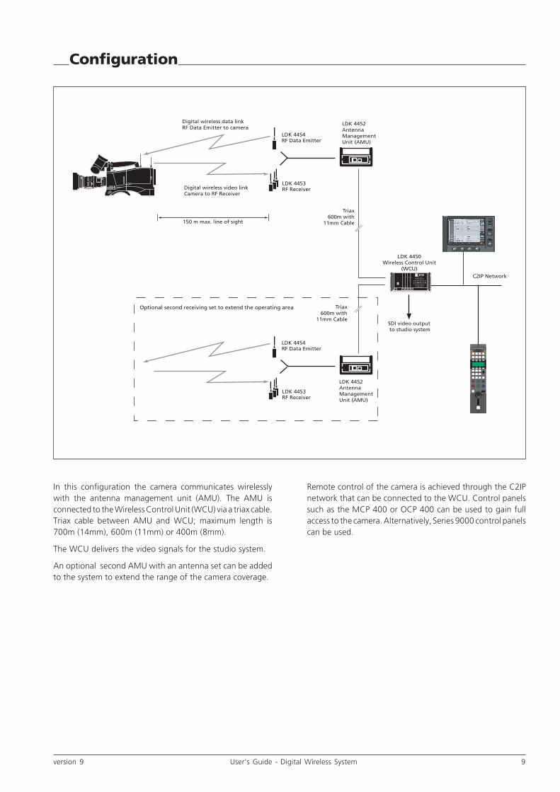
In this configuration the camera communicates wirelesslywith the antenna management unit (AMU). The AMU isconnected to the Wireless Control Unit (WCU) via a triax cable.Triax cable between AMU and WCU; maximum length is700m (14mm), 600m (11mm) or 400m (8mm).
The WCU delivers the video signals for the studio system.
An optional second AMU with an antenna set can be addedto the system to extend the range of the camera coverage.
Configuration
LDK 4453RF Receiver
LDK 4454RF Data Emitter
LDK 4452Antenna Management Unit (AMU)
LDK 4450Wireless Control Unit
(WCU)
Triax600m with
11mm Cable
Digital wireless video link Camera to RF Receiver
Digital wireless data link RF Data Emitter to camera
LDK 4453RF Receiver
LDK 4454RF Data Emitter
LDK 4452Antenna Management Unit (AMU)
Triax600m with
11mm CableSDI video output to studio system
Optional second receiving set to extend the operating area
150 m max. line of sight
C2IP Network
Remote control of the camera is achieved through the C2IPnetwork that can be connected to the WCU. Control panelssuch as the MCP 400 or OCP 400 can be used to gain fullaccess to the camera. Alternatively, Series 9000 control panelscan be used.
10 User’s Guide - Digital Wireless System version 9
Setting up the camera adapter
!
coaxial cable
flatcable
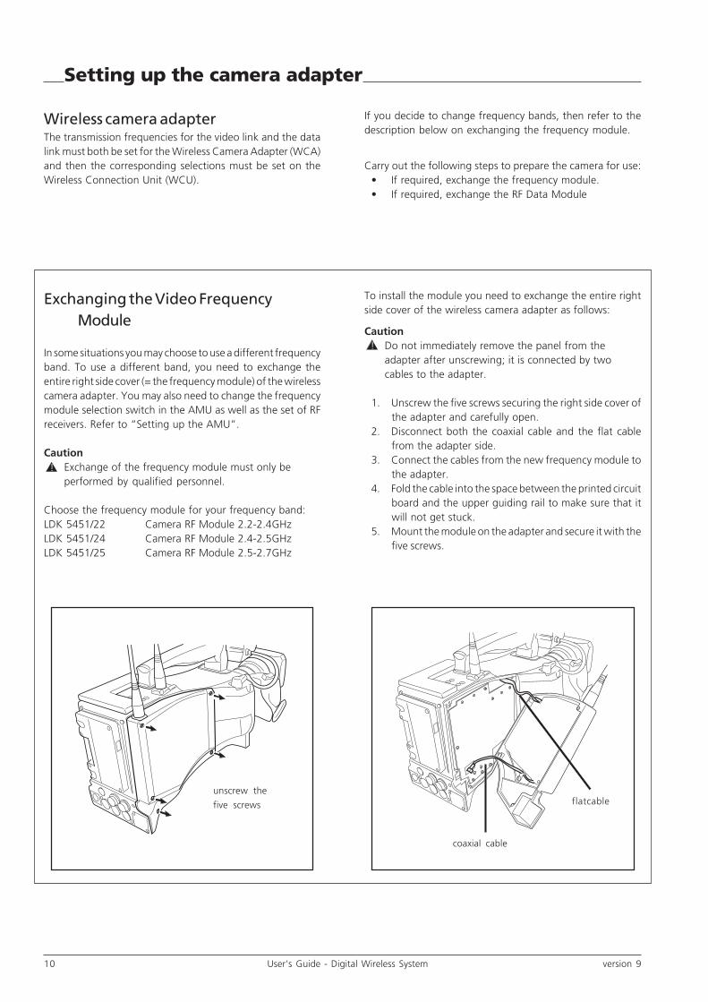
Exchanging the Video FrequencyModule
In some situations you may choose to use a different frequencyband. To use a different band, you need to exchange theentire right side cover (= the frequency module) of the wirelesscamera adapter. You may also need to change the frequencymodule selection switch in the AMU as well as the set of RFreceivers. Refer to “Setting up the AMU”.
CautionExchange of the frequency module must only beperformed by qualified personnel.
Choose the frequency module for your frequency band:LDK 5451/22 Camera RF Module 2.2-2.4GHzLDK 5451/24 Camera RF Module 2.4-2.5GHzLDK 5451/25 Camera RF Module 2.5-2.7GHz
!
Wireless camera adapterThe transmission frequencies for the video link and the datalink must both be set for the Wireless Camera Adapter (WCA)and then the corresponding selections must be set on theWireless Connection Unit (WCU).
If you decide to change frequency bands, then refer to thedescription below on exchanging the frequency module.
Carry out the following steps to prepare the camera for use:• If required, exchange the frequency module.• If required, exchange the RF Data Module
unscrew the
five screws
To install the module you need to exchange the entire rightside cover of the wireless camera adapter as follows:
CautionDo not immediately remove the panel from theadapter after unscrewing; it is connected by twocables to the adapter.
1. Unscrew the five screws securing the right side cover ofthe adapter and carefully open.
2. Disconnect both the coaxial cable and the flat cablefrom the adapter side.
3. Connect the cables from the new frequency module tothe adapter.
4. Fold the cable into the space between the printed circuitboard and the upper guiding rail to make sure that itwill not get stuck.
5. Mount the module on the adapter and secure it with thefive screws.

version 9 User’s Guide - Digital Wireless System 11
Setting up the camera adapter (cont.)
!
Exchanging the RF Data Module
In some situations you may choose to use a different frequencyfor the data channel. To use a different frequency, you needto exchange the RF Data Module inside the camera wirelessadapter. You may also need to change the frequency moduleselection switch in the AMU as well as the Data Emitter. Referto the section“Setting up the AMU”.
CautionExchange of the RF Data Module must only beperformed by qualified personnel.
Choose the RF Data Module for the frequency you want touse:LDK 4456/10 Camera RF Data Module 433 MHzLDK 4456/20 Camera RF Data Module 456 MHz
To install the module you need to exchange RF Data Moduleentire right side cover of the wireless camera adapter asfollows:
1. Unscrew the five screws securing the left side cover ofthe adapter and carefully open. Handle the flatcable atthe bottom very carefully.
2. Locate the RF Data Module Board (third one from theleft) and disconnect the coaxial cable from the board.
3. Pull out the board gently.4. Insert the new board and push until it firmly locks into
its socket.5. Attach the coaxial cable to the board.5. Replace the cover on the adapter and secure it with the
five screws.
• Attach the adapter to the camera.• Attach the antennas to the adapter.• Power the camera via the adapter.• Select the video frequency via the camera menu.• Select the data frequency via the camera menu.• Select the camera number via the camera menu.
RF Data Module Board
Coaxial cable

12 User’s Guide - Digital Wireless System version 9
Setting up the camera adapter (cont.)
ClearClear
A 1
Star 4PND1/4
B 2
Star 6PND 1/16
C 3
Soft focusND 1/64
D 4
Attaching the adapter to the camera
Caution
Be extremely careful with the connectors betweenthe camera head and the adapter. Do not allowthe guide pins to damage the pins of theconnector.
Follow these steps in the order given. Tighteningthe screws in the wrong order could result inmechanical damage to the camera.
To attach an adapter to the camera proceed as follow:a. Using the rail 1 on the bottom of the camera head as
a guide, fit the guide pins 2 on either side of theconnector and the guide pin 3 at the top rear of thecamera head into the corresponding slots of the adapter.
b. First, tighten the two horizontal screws 4 on the top ofcamera.
c. Next, tighten the two horizontal screws 5 at the frontof the camera.
d. Lastly, tighten the vertical screw 6 in the handle of thecamera.
To detach an adapter from the camera head follow the stepsfor attaching it in the reverse order.
Caution
Loosening the screws in the wrong order couldresult in mechanical damage to the camera.
!
!
!5
6
4
3
2 1

version 9 User’s Guide - Digital Wireless System 13
Attaching antennas to the camera adapter
!
!
!
Data Link
antenna
Video Link
antenna
Attaching antennas to the adapterThe wireless camera adapter uses two different antennas: aData Link antenna and a Video Link antenna:
Identification ring
Video Link antenna
The following tables show which antenna to use for thechosen frequency ranges:
Video frequency: Identification ring:
[2.2-2.4] GHz Red ring + no. ‘2’
[2.4-2.5] GHz (ISM) Yellow ring + no. ‘4’
[2.5-2.7] GHz Green ring + no. ‘5’
Data frequency: Antenna type:
433 MHz T9006720 (18 cm)
456 MHz 25814730 (17.5 cm)
Attach both antennas securely to the wireless adapter.
Caution
Never supply power to an adapter without firstensuring that the antennas are attached.
Always use the antenna that was supplied withthe frequency module. Using the wrong antennawill result in poor coverage.
Switch off the power to the units beforedetaching the antennas.
14 User’s Guide - Digital Wireless System version 9
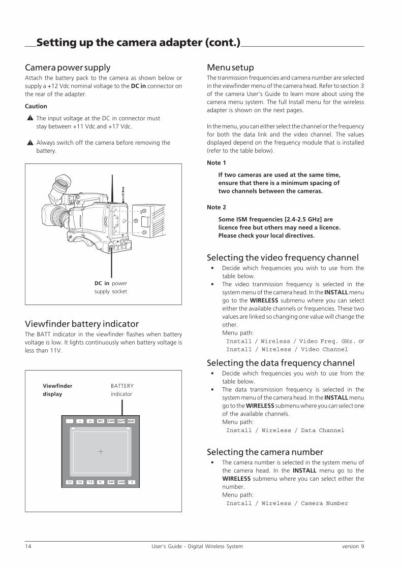
Camera power supplyAttach the battery pack to the camera as shown below orsupply a +12 Vdc nominal voltage to the DC in connector onthe rear of the adapter.
Caution
The input voltage at the DC in connector muststay between +11 Vdc and +17 Vdc.
Always switch off the camera before removing thebattery.
DC in power
supply socket
!
!
Setting up the camera adapter (cont.)
Menu setupThe tranmission frequencies and camera number are selectedin the viewfinder menu of the camera head. Refer to section 3of the camera User’s Guide to learn more about using thecamera menu system. The full Install menu for the wirelessadapter is shown on the next pages.
In the menu, you can either select the channel or the frequencyfor both the data link and the video channel. The valuesdisplayed depend on the frequency module that is installed(refer to the table below).
Note 1
If two cameras are used at the same time,ensure that there is a minimum spacing oftwo channels between the cameras.
Note 2
Some ISM frequencies [2.4-2.5 GHz] arelicence free but others may need a licence.Please check your local directives.
Selecting the video frequency channel• Decide which frequencies you wish to use from the
table below.• The video tranmission frequency is selected in the
system menu of the camera head. In the INSTALL menugo to the WIRELESS submenu where you can selecteither the available channels or frequencies. These twovalues are linked so changing one value will change theother.Menu path:Install / Wireless / Video Freq. GHz. orInstall / Wireless / Video Channel
Selecting the data frequency channel• Decide which frequencies you wish to use from the
table below.• The data transmission frequency is selected in the
system menu of the camera head. In the INSTALL menugo to the WIRELESS submenu where you can select oneof the available channels.Menu path:Install / Wireless / Data Channel
Selecting the camera number• The camera number is selected in the system menu of
the camera head. In the INSTALL menu go to theWIRELESS submenu where you can select either thenumber.Menu path:Install / Wireless / Camera Number
BATTERY
indicator
ND/REBATTTAPEREC+++-
!AW2AW1FL7.55.63.2
Viewfinder battery indicatorThe BATT indicator in the viewfinder flashes when batteryvoltage is low. It lights continuously when battery voltage isless than 11V.
Viewfinder
display

version 9 User’s Guide - Digital Wireless System 15
Frequency table for Video modules:WCA WCU Module Module Module
Channel Channel [2.2-2.4 GHz] ISM-[2.4-2.5 GHz] [2.5 - 2.7 GHz]
0 0 2200.0 MHz 2394.0 MHz 1) 2) 2500.0 MHz 1)
1 1 2212.0 MHz 2404.0 MHz 2) 2512.0 MHz 1)
2 2 2225.0 MHz 2411.0 MHz 2525.0 MHz
3 3 2237.0 MHz 2418.0 MHz 2537.0 MHz
4 4 2250.0 MHz 2425.0 MHz 2550.0 MHz
5 5 2262.0 MHz 2432.0 MHz 2562.0 MHz
6 6 2275.0 MHz 2439.0 MHz 2575.0 MHz
7 7 2287.0 MHz 2446.0 MHz 2587.0 MHz
8 8 2300.0 MHz 2453.0 MHz 2600.0 MHz
9 9 2312.0 MHz 2460.0 MHz 2612.0 MHz
10 A 2325.0 MHz 2467.0 MHz 2625.0 MHz
11 B 2337.0 MHz 2474.0 MHz 2) 2637.0 MHz
12 C 2350.0 MHz 2483.0 MHz 2) 2650.0 MHz
13 D 2362.0 MHz 2490.0 MHz 2) 2662.0 MHz
14 E 2375.0 MHz 2497.0 MHz 2) 2675.0 MHz
15 F 2387.0 MHz 1) 2504.0 MHz 1) 2) 2687.0 MHz
Notes1) As the highest channels of some modules may interfere with the lowest channels of other modules it is not recommended to usethese settings simultaneously for systems in the same operating space. The minimum frequency distance is 12 Mhz.
2) The use of some frequencies my require a radio licence.
Frequency table for Data modules:WCA WCU Data Emitter Data Emitter
Channel Channel (433 MHz) (456 MHz)
0 0 433.10 MHz 455.00 Mhz
1 1 433.20 MHz 455.10 Mhz
2 2 433.30 MHz 455.20 Mhz
3 3 433.40 MHz 455.30 Mhz
4 4 433.50 MHz 455.40 Mhz
5 5 433.60 MHz 455.50 Mhz
6 6 433.70 MHz 455.60 Mhz
7 7 433.80 MHz 455.70 Mhz
8 8 433.90 MHz 455.80 Mhz
9 9 434.00 MHz 455.90 Mhz
10 A 434.10 MHz 456.00 Mhz
11 B 434.20 MHz 455.15 Mhz
12 C 434.30 MHz 455.25 Mhz
13 D 434.40 MHz 455.40 Mhz
14 E 434.50 MHz 455.55 Mhz
15 F 434.60 MHz 455.70 Mhz
Setting up the camera adapter (cont.)
16 User’s Guide - Digital Wireless System version 9
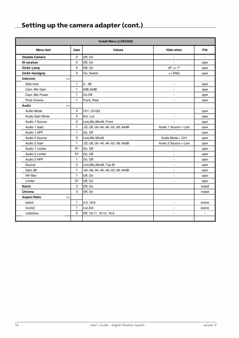
Setting up the camera adapter (cont.)
Menu text User Values Hide when File
Disable Camera Off, On - -
IR receiver Off, On - oper
OnAir Lamp Off, On VF <> 7" oper
OnAir Handgrip On, Switch <> ENG oper
Intercom >>
Side tone 0…99 - oper
Cam. Mic Gain 0dB,40dB - oper
Cam. Mic Power On,Off - oper
Prod Volume Front, Rear - oper
Audio >>
Audio Mode Ch1, Ch1&2 oper
Audio Gain Mode Ext, Loc - oper
Audio 1 Source Line,Mic,Mic48, Front - oper
Audio 1 Gain -22,-28,-34,-40,-46,-52,-58,-64dB Audio 1 Source = Line oper
Audio 1 HPF On, Off - oper
Audio 2 Source Line,Mic,Mic48 Audio Mode = Ch1 oper
Audio 2 Gain -22,-28,-34,-40,-46,-52,-58,-64dB Audio 2 Source = Line oper
Audio 1 Limiter On, Off - oper
Audio 2 Limiter On, Off - oper
Audio 2 HPF On, Off - oper
Source Line,Mic,Mic48, Top M - oper
Gain dB -22,-28,-34,-40,-46,-52,-58,-64dB - oper
HP filter Off, On - oper
Limiter Off, On - oper
Notch Off, On install
Chroma Off, On install
Aspect Ratio >>
select 4:3, 16:9 - scene
loc/ext Loc,Ext - scene
Letterbox Off, 16:11, 16:10, 16:9 - -
1
1
0
3
3
0
1
S1
0
S1
1
1
Install Menu (LDK5450)
1
0
0
1
1
1
1
0
0
0
0
1
0
1
S1
version 9 User’s Guide - Digital Wireless System 17
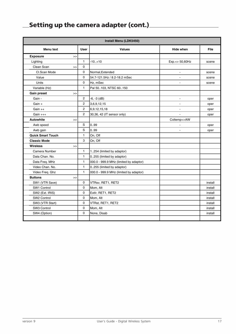
Setting up the camera adapter (cont.)
Menu text User Values Hide when File
Exposure >>
Lighting -10..+10 Exp.<> 50,60Hz scene
Clean Scan >>
Cl.Scan Mode Normal,Extended - scene
Value 54.7-121.5Hz / 8.2-18.2 mSec - scene
Units Hz, mSec - scene
Variable (Hz) Pal 50..103, NTSC 60..150
Gain preset >>
Gain - -6, -3 (dB) - oper
Gain + 3,6,9,12,15 - oper
Gain ++ 6,9,12,15,18 - oper
Gain +++ 30,36, 42 (IT sensor only) - oper
Autowhite >> Coltemp<>AW
Awb speed 0..99 - oper
Awb gain 0..99 - oper
Quick Smart Touch On, Off
Classic Mode On, Off
Wireless >>
Camera Number 1..254 (limited by adaptor)
Data Chan. No. 0..255 (limited by adaptor)
Data Freq. MHz 000.0 - 999.9 MHz (limited by adaptor)
Video Chan. No. 0..255 (limited by adaptor)
Video Freq. Ghz 000.0 - 999.9 MHz (limited by adaptor)
Buttons >>
SW1 (VTR Save) VTRsv, RET1, RET2 install
SW1 Control Mom, Alt install
SW2 (Ext. IRIS) ExtIr, RET1, RET2 install
SW2 Control Mom, Alt install
SW3 (VTR Start) VTRst, RET1, RET2 install
SW3 Control Mom, Alt install
SW4 (Option) None, Disab install
0
0
0
1
1
1
1
1
0
0
0
0
S
S
3
1
2
2
2
1
Install Menu (LDK5450)
1
2
0
0
0
0

18 User’s Guide - Digital Wireless System version 9
AMU IDENTIFIER
VIDEO CHANNEL
DATA CHANNEL
lock error ANT1
2
3
POWER
AMU IDENTIFIER
The display shows the number of the AMU (to identify AMUswhen there are two AMUs in a system). This number alsoappears in the viewfinder at the bottom right.
When the AMU automatically switches to long distance triaxmode the decimal dot in the display lights.
VIDEO CHANNEL
The display shows the channel number on which the wirelessvideo signal from the camera is transmitted (set on WCU).
DATA CHANNEL
The display shows the channel number on which the wirelesscontrol signal to the camera is transmitted (set on WCU). Adash (-) indicates that no data emitter is connected.
When the AMU detects that a 456 MHz Data Emitter isconnected, the decimal dot in the display lights.
1
2
LOCK
These three green indicators, whose numbers correspondto the three transmission antennas, light to indicate thatthere is a connection between camera and the specificAMU antenna. At least one of these indicators must be litto have a connection. If all three are lit, then the RF link isat its strongest.
ERROR
A red indicator lights to indicate a problem (uncorrectableerrors) in the connection between the camera and a specificAMU antenna. The connection remains reliable as long as allthree indicators do not light at the same time.
POWER
This indicator lights when power from the WCU is suppliedto the AMU via the triax cable.
3
4
5
6
3 4 6521
AMU indicators

version 9 User’s Guide - Digital Wireless System 19
TRIAX OUTPUT
IF1 IF2 IF3
DATA CAM TRANSMITTER
IN IN
OUT OUT
AMU and antenna positioningPosition the AMU at the centre of the area you wish to cover.Mount the antenna assembly on a mast or attach it to a raisedstructure. If required a second AMU can be used to extend thecovered area.
HintTo cover a typical stage area, it might be a goodidea to place the antenna assembly upside-downat a high point on either side of the stage.
Antenna unitSet up the antenna support assembly close to the AMU asfollows:
1. Unfold the antenna support assembly.2. Attach the three antenna receiver units to the ends of
the arms.3. Attach the data receiver unit to the centre of the
assembly.4. Screw the three antennas with SMA connector onto the
antenna receiver units.5. Connect the data antenna with BNC connector to the
data transmission unit. There are two types of antennaavailable:
Setting up the AMU
Mount the
antenna support
on a tripod or
other support.
Triax cable
Data connectorVideo antenna
connectors (BNC)
LDK 4454/10 (433 MHz) uses T9006720 antennaLDK 4454/20 (456 MHz) uses 25814730 antenna
6. Connect the three BNC coaxial connectors of thesupplied cable to the antenna receiver units.
7a. Connect the 9-pin sub-D connector to the datatransmission unit.
7b. If your antenna support assembly has a Data Boosterconnect the 2 pin LEMO connector to the Data Boosterunit.
Caution.
Always use the antennas that were supplied withthe modules. Using the wrong antennas willresult in poor coverage.
AMU connectors8. Connect the three coaxial cables from the antennas to
the upper row of BNC video connectors on the AMU.9. Connect the cable from the data antenna to the 9-pin,
sub-D connector on the AMU.10. Connect the triax cable (<600m of 11mm triax cable) to
the Triax output of the AMU (TRIAX output).
!

20 User’s Guide - Digital Wireless System version 9
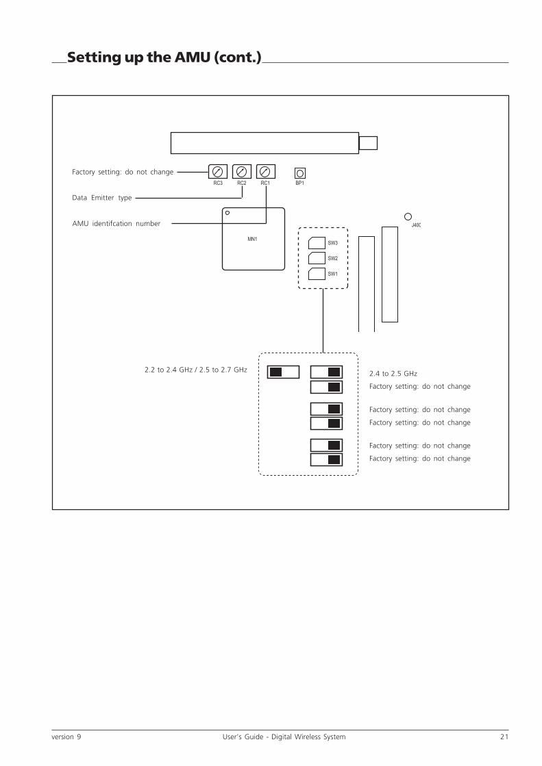
Setting up the AMU (cont.)
AMU identification numberIf more than one AMU is used, each AMU must be given aunique identification number. The AMU identification numberis shown on the upper display on the side of the AMU. Youmay choose any possible identification number as long as youchoose a different one for each AMU in the system.
Caution
Disconnect the power to the WCU beforeopening the AMU.
To change the AMU identification number proceed as follows:1. Ensure power is disconnected.2. Open the AMU by removing the four screws underneath
the sun cover and tilt open the lid of the case.3. Find the row of three rotary switches on the main print
panel (refer to the drawing).4. Set the rotary switch (RC1) on the far right to the number
you want for the AMU.5. Close the cover and tighten the screws carefully.
Video frequency selectionIf you change the frequency module on the wireless cameraadapter, it may be necessary to change the setting of theAMU.
To change the AMU frequency module setting proceed asfollows:
1. Ensure power is disconnected.2. Open the AMU by removing the four screws underneath
the sun cover and tilt open the cover of the case.3. Find the row of three microswitches on the main print
panel.4. Use a thin screw driver to access the microswitch SW3.1.5. If an ISM [2.4-2.5] GHz module is used, set this switch
to the RIGHT position. For other modules set this switchto LEFT position.
6. Close the cover. Tighten the screws bit by bitcounterclockwise and one after the other to ensuresteady pressure on the waterproof gasket.
!
Note
Switches SW1, SW2 and RC3 and BP1 arestandard factory settings for the board’s logiccircuits. Do not change these switches.
!
Setup switches
AMU IDENTIFIER
VIDEO CHANNEL
DATA CHANNEL
lock error ANT1
2
3
POWER
AMU identification number display
Data frequency selectionIf you change the Data module on the wireless cameraadapter, it may be necessary to change the setting of theAMU.
To change the AMU Data module setting proceed as follows:
1. Ensure power is disconnected.2. Open the AMU by removing the four screws underneath
the sun cover and tilt open the cover of the case.3. Find the row of three rotary switches on the main print
panel (refer to the drawing).4. Use a thin screw driver to access the rotary switch RC2.5. If an 443 MHz module is used, set the switch to
position F. For other modules (e.g. 456 MHz) set theswitch to position E.
6. Close the cover. Tighten the screws bit by bitcounterclockwise and one after the other to ensuresteady pressure on the waterproof gasket.
version 9 User’s Guide - Digital Wireless System 21
2.4 to 2.5 GHz
RC1 BP1RC2RC3
MN1
J400
SW3
SW2
SW1
2.2 to 2.4 GHz / 2.5 to 2.7 GHz
Factory setting: do not change
Factory setting: do not change
Factory setting: do not change
Factory setting: do not change
Factory setting: do not change
Factory setting: do not change
Data Emitter type
AMU identifcation number
Setting up the AMU (cont.)

22 User’s Guide - Digital Wireless System version 9
TRIAX 1 OK
CAM LOCK
ON
ON AIR
MAINS
I
0OFF
CABLEOPEN
EXT REF
SC
SC/H
FRONTPORCH
CCUPOWER
GENLOCKVIDEO
TRIAX 2 OK
PC OK
TRIAX 1SELECTED
TRIAX 2SELECTED
VIDEO CHANNEL
VIDEO PARAMS
DATA CHANNEL
CAMERA
DATABOARD
TRIAX
FREEZE
FREE RUN
COARSE
FINE
AUDIO I/COM
1 2 3
4 5
7 14 15 16
WCU Controls and indicators
8
136 1211
PC OK
Only used when a remote PC is connected to the front plugof the WCU Audio Board. In this case the light indicates thestatus of the PC to WCU dialog:
PC OK PC Message:
(Green) connected
Off No Internal switch configuration of
Digital Triax is OK.
Flashing No Internal switch configuration of
Digital Triax is not OK.
Toggling Yes Dialog busy. Toggling indicates
transfer speed.
TRIAX 1 OK / SELECTED
Normally lit, these lights indicates that the signal from theAMU is present and selected. Flashing indicates no camera;Off indicates no AMU.
Triax Sel. Triax OK Message:
(Green) (Orange)
On On Triax input is selected. Video
transmission in Triax is OK.
Off On Triax input is not selected. Video
transmission in Triax is OK.
On Off Video transmission in Triax is
not OK.
Flashing - AMU is not acknowledging
control data sent by WCU.
TRIAX 2 OK / SELECTED
These lights indicate that a signal from a second AMU ispresent and selected.
9 10
VIDEO CHANNEL
This rotary switch selects the video transmission channel.
DATA CHANNEL
This rotary switch selects the data transmission channel.
VIDEO PARAMS
No function, not used.
CAM LOCK
When ON the WCU is receiving a live video signal from thecamera. Flashes during Freeze or Power Up sequence of theWCU.
EXT REF.
When ON this light indicates the presence of a correct externalsync signal on the GEN LOCK connector of the WCU. Otherwiseis is off or flashing.
FREEZE
When ON, this light indicates that Freeze Mode is activateddue to an interrupted video connection.
FREE RUN
Always Off. Not used.
FRONT PORCH
Adjustment of the front porch for encoded video signal.
SUBCARRIER (SC)
Subcarrier phase adjustment for encoded video signal.
1
2
3
8
4
5
6
7
9
11
12
10

version 9 User’s Guide - Digital Wireless System 23
HORIZONTAL PHASE
Use COARSE and FINE adjustment for encoded video signal.
CAMERA
ONNormally and permanently ON, this light indicates thatthe WCU is powered. This indicator flashes to indicateexcessive consumption at the WCU.
OFFThis indicator lights when the AMU is not drawingpower. This indicator flashes to indicate that the AMUconsumption is excessively low (<26 W).
CABLE OPENThis normally OFF indicator lights if there is no DigitalTriax Rack in the WCU.
ON AIR
When ON, this light indicates that the camera signal is on air(ON AIR1).
MAINS
The equipment master on/off switch:«I»: The equipment is operating.«O»: The equipment is not operating.
13
14
15
16
Setting up the WCU
TRIAX 1 OK
CAM LOCK
ON
ON AIR
MAINS
I
0OFF
CABLEOPEN
EXT REF
SC
SC/H
FRONTPORCH
CCUPOWER
GENLOCKVIDEO
TRIAX 2 OK
PC OK
TRIAX 1SELECTED
TRIAX 2SELECTED
VIDEO CHANNEL
VIDEO PARAMS
DATA CHANNEL
CAMERA
DATABOARD
TRIAX
FREEZE
FREE RUN
COARSE
FINE
AUDIO I/COM
RS-232 connector
Data Board
Video channel
Data channel
Rotary/push button
Camera number / menu display
WCU connections1. Connect the triax cable from the AMU to the Triax
input 1 of the WCU. (If you use a second AMU, connectit to Triax input 2 of the WCU.)
2. Connect the OCP to the C2IP network.3. Connect the SDI outputs of the WCU to the studio
system.4. If required provide a reference signal (H/V) to the
Genlock input of the WCU.5. Connect the WCU to the mains power.
After you have made the connections to the WCU, you can setup the following items:
• Video frequency• Data frequency• Camera number (set in the WCU menu)• Signalling (set in the WCU menu)
Set the video frequency channel• Turn the VIDEO CHANNEL rotary switch on the front of
the WCU to the same number that you set for the videotransmission frequency in the WCA.
Set the data frequency channel• Turn the DATA CHANNEL rotary switch on the front of
the WCU to the same number that you set for the datatransmission frequency in the WCA.
Set the camera number• Refer to the description of how to select a WCU menu
setting to set the camera number to the same numberyou selected in the camera menu.
WCU Controls..
24 User’s Guide - Digital Wireless System version 9
WCU menu settingsSome WCU settings are changed in a menu which is accessedvia the Data board. When you enter the menu system, the Databoard display shows a two-letter abbreviation which must beread from top to bottom. The code corresponds to a particularmenu, submenu or parameter. To change a WCU menusetting proceed as follows:
1. Remove the front panel marked DATA BOARD from theWCU.
2. Reach into the opening, push the Rotary/push buttonat the front of the Data board and then rotate it.
3. Scroll through the different settings until the displayshows the abbreviated name you want.
4. Push the Rotary/push button to select the submenu,scroll to the desired setting and push the Rotary/pushbutton again to select it.
5. Push the Rotary/push button again to leave the menu.
The following menus are available:CA - Camera number
Each camera in the system can be given a unique cameranumber. This number must be set in the camera, theWCU and a connected OCP if present.To set the camera number in the WCU push the rotary/push button and use the rotary button to select a
Setting up the WCU (cont.)
camera number from 1 to 99. Push again to select thenumber.
IP - Ethernet address modeThe WCU is set to Auto (AU) mode by default. Normallyyou need not change this setting. If you wish to set theIP address to a particular value push the rotary switchonce so the indication (NN) is displayed. You must usethe NetConfig application to set the IP address (futureoption).
RY - On-air red/yellow modeStandard (ST) or Independent (ID).
OR - On-air red modeOpen/High (OH); High/Open (HO); Low/High (LH) orHigh/Low (HL).
OY - On-air yellow modeOpen/High (OH); High/Open (HO); Low/High (LH) orHigh/Low (HL).
CL - Call input modeOpen/High (OH); High/Open (HO); Low/High (LH) orHigh/Low (HL).
OF - 7-segment display offWhen selected, the menu display automatically switchesoff after a few seconds.
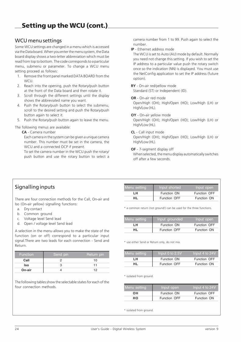
a. Dry contact (no ground, no voltage)*
* a common return (not ground!) can be used for the three functions.
b. Common ground (connect one lead only to ground)*
* use either Send or Return only, do not mix.
c. Voltage level Send lead (0 to 2.5 Vdc, 4 to 24 Vdc)*
* isolated from ground.
d. Open / voltage level Send lead (open, 4 to 24 Vdc)*
* isolated from ground.
Signalling inputs
There are four connection methods for the Call, On-air andIso (On-air yellow) signalling functions:
a. Dry contactb. Common groundc. Voltage level Send leadd. Open / voltage level Send lead
A selection in the menu allows you to make the state of thefunction (on or off) correspond to a particular inputsignal.There are two leads for each connection - Send andReturn.
The following tables show the selectable states for each of thefour connection methods.
Menu setting Input shorted Input open
LH Function ON Function OFF
HL Function OFF Function ON
Menu setting Input grounded Input open
LH Function ON Function OFF
HL Function OFF Function ON
Menu setting Input 0 to 2.5V Input 4 to 24V
LH Function ON Function OFF
HL Function OFF Function ON
Menu setting Input open Input 4 to 24V
OH Function ON Function OFF
HO Function OFF Function ON
Function Send pin Return pin
Call 2 10
Iso 3 11
On-air 4 12

version 9 User’s Guide - Digital Wireless System 25
Audio
Audio/Intercom DIP switch settings (S660-S664):
Switch Setting
SP1 keep always disabled; factory setting
SP2 normally disabled. When enabled, a 1kHz
intercom tone from WCU to WCA is
digitally synthesized for test purposes.
REMOTE not connected; no function
DELAY enable to activate audio/video delay
compensation
ICOM 6dB enabled: nominal i/com input is +6dBu
disabled: nominal i/com input is 0dBu
(recommend position is enabled).
AUD 6dB enabled: nominal audio output is +6dBu
disabled: nominal audio output is 0dBu
AUD DUAL normally disabled. When enabled linear
intercom is achieved. Only use this
setting when a compressor is available!
When disabled, a digital intercom
compressor is activated.
ICOM 4W enabled: 4-wire mode intercom is selected
disabled: 2-wire mode intercom is selected
PRIV.DATA always keep disabled; factory setting.
ISOLATE ICOM when enabled all intercom input and output
signals are isolated
Audio settingsThe following are the settings for the audio signals appliedto the rear of the wireless adapter and the side of the camerahead. They can be made in the camera head menu and on theAudio/Intercom board of the WCU:
Select 1 or 2 audio channels• The number of audio channels is selected in the systems
menu of the camera head. In the INSTALL menu go tothe Audio submenu where you can select either 1 or 2.Menu path:Install / Audio / Audio Mode
Select audio gain mode• The audio gain mode is selected in the systems menu
of the camera head. In the INSTALL menu go to theAudio submenu where you can select whether GainControl is LOCAL (under VF menu control) or EXTERNAL(under MCP control or resistor chain control in theWCU)Menu path:Install / Audio / Audio Gain Mode
TRIAX 1 OK
CAM LOCK
ON
ON AIR
MAINS
I
0OFF
CABLEOPEN
EXT REF
SC
SC/H
FRONTPORCH
CCUPOWER
GENLOCKVIDEO
TRIAX 2 OK
PC OK
TRIAX 1SELECTED
TRIAX 2SELECTED
VIDEO CHANNEL
VIDEO PARAMS
DATA CHANNEL
CAMERA
DATABOARD
TRIAX
FREEZE
FREE RUN
COARSE
FINE
AUDIO I/COM
Audio/Intercom Board
K
12
S664
K
12
S663
K
12
S662
K
12
S661
K
12
S660
MN600
C0900 C0910
MN630
P3
Disable Enable
SP1SP2
ICOM 6dBAUD 6dB
RemoteDelay
AUD DUALICOM 4W
PRIV. DATAISOL. ICOM
Two-wire balance
Intercom output volume
Follow the Disable and Enable positions shown in this
drawing. Ignore the screening on the board itself.
Select audio source• The audio source is selected in the systems menu of the
camera head. In the INSTALL menu go to the Audiosubmenu where you can select the source.Menu path:Install / Audio / Audio Source
Select audio gain• The audio gain is set in the system menu of the camera
head. In the INSTALL menu go to the Audio submenuwhere you can set the gain for both channels.Menu path:Install / Audio / Audio 1(2) Gain
Select audio output level and delay• Ensure power is disconnected.• Remove the board marked Audio/Intercom from the
WCU.• Locate the AUD 6dB DIP-switch on the board.• Use the table below to set the audio output level to
enable (+6dB) or disable (0dB).• Locate the DELAY DIP-switch on the board.• Use the table below to enable the Delay function. (The
audio delay function delays the audio signal so that itis synchronised with the video signal.)
26 User’s Guide - Digital Wireless System version 9
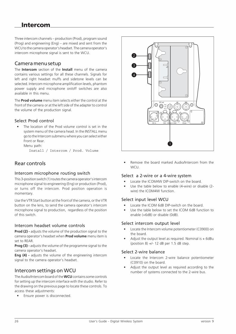
Intercom
Three intercom channels – production (Prod), program sound(Prog) and engineering (Eng) – are mixed and sent from theWCU to the camera operator's headset. The camera operator'sintercom microphone signal is sent to the WCU.
Camera menu setupThe Intercom section of the Install menu of the cameracontains various settings for all these channels. Signals forleft and right headset muffs and sidetone levels can beselected. Intercom microphone amplification levels, phantompower supply and microphone on/off switches are alsoavailable in this menu.
The Prod volume menu item selects either the control at thefront of the camera or at the left side of the adapter to controlthe volume of the production signal.
Select Prod control• The location of the Prod volume control is set in the
system menu of the camera head. In the INSTALL menugo to the Intercom submenu where you can select eitherFront or Rear.Menu path:
Install / Intercom / Prod. Volume
Rear controls
Intercom microphone routing switchThis 3-position switch (1) routes the camera operator's intercommicrophone signal to engineering (Eng) or production (Prod),or turns off the intercom. Prod position operation ismomentary.
Use the VTR Start button at the front of the camera, or the VTRbutton on the lens, to send the camera operator's intercommicrophone signal to production, regardless of the positionof this switch.
Intercom headset volume controlsProd (2) - adjusts the volume of the production signal to thecamera operator's headset when Prod volume menu item isset to REAR.Prog (3) - adjusts the volume of the programme signal to thecamera operator's headset.Eng (4) - adjusts the volume of the engineering intercomsignal to the camera operator's headset.
Intercom settings on WCUThe Audio/Intercom board of the WCU contains some controlsfor setting up the intercom interface with the studio. Refer tothe drawing on the previous page to locate these controls. Toaccess these adjustments:
• Ensure power is disconnected.
DC out VF SDI
I/ComCH2CH1DC in Audio in
Eng
Off
Prod
3
4
2
1
• Remove the board marked Audio/Intercom from theWCU.
Select a 2-wire or a 4-wire system• Locate the ICOM4W DIP-switch on the board.• Use the table below to enable (4-wire) or disable (2-
wire) the ICOM4W function.
Select input level WCU• Locate the ICOM 6dB DIP-switch on the board.• Use the table below to set the ICOM 6dB function to
enable (+6dB) or disable (0dB).
Select intercom output level• Locate the Intercom volume potentiometer (C0900) on
the board.• Adjust the output level as required. Nominal is + 6dBu
(position 8) +/- 12 dB per 1.5 dB step.
Select 2-wire balance• Locate the Intercom 2-wire balance potentiometer
(C0910) on the board.• Adjust the output level as required according to the
number of systems connected to the 2-wire bus.

version 9 User’s Guide - Digital Wireless System 27
DC out VF SDI
I/ComCH2CH1DC in Audio in
Eng
Off
Prod
WCA connectors
Back panel view
3 4
6
521
7

28 User’s Guide - Digital Wireless System version 9
Hirose 6-pin female; panel view1. Ground (Video)2. Video Input (1Vpp CVBS)3. DC Out (+11Vdc to +17 Vdc), 1.5A max.4. Ground (DC out)5. not connected6. Tally signal (limited current = 10 mA)
Shield of cable directly to the connector housing.
- chassis part (female): Hirose HR10A-7R-6S (3922 200 00038)- cable part (male): Hirose HR10A-7P-6P
(1) DC power output socket
(2) DC power input socket
XLR 4-pin male; panel view1. Ground2. No connection3. No connection4. +11 Vdc . . . +17 Vdc
This socket accepts a DC voltage of 12V nominal. Maximum nominalpower consumption 38W (excluding power out socket).
CAUTIONThe input voltage must not exceed +17 Vdc.!
1
2 3
4
1
6
5
2
3
4
WCA connectors (cont.)
XLR 3-pin female1. Audio Screen2. Audio In3. Audio Return
Input impedance > 10 KOhm
Sensitivity range: -64 to -22 dBu or line (0dBu)Signal at pin 2 of audio input is in phase with signal at pin 2 of audiooutput. Switchable phantom power: +48 V
(3) Audio IN (CH1) microphone connector
XLR 3-pin female1. Audio Screen2. Audio In3. Audio Return
Input impedance > 10 KOhm
Sensitivity range: -64 to -22 dBu or line (0dBu)Signal at pin 2 of audio input is in phase with signal at pin 2 of audiooutput. Switchable phantom power: +48 V
(4) Audio IN (CH2) microphone connector
3
1
2
3
1
2

version 9 User’s Guide - Digital Wireless System 29
WCA connectors (cont.)
(6) Camera SDI output connector
(7) VF output connector
BNC connectorThis socket provides a 1.0Vpp VBS output of the viewfinder signal.
BNC connectorThis socket provides a 0.8Vpp SDI output video signal formonitoring purposes only.
XLR 5-pole female; panel view1. Microphone return2. Microphone3. Telephone return4. Telephone left5. Telephone right
Microphone level -44 dBu / -24 dBu switchableInput impedance > 10 KOhm.Switchable phantom power: +12 V
Telephone level +12 dBu nominalTelephone output impedance <50 Ohm
(5) Intercom headset connector
1
2
3
4
5

30 User’s Guide - Digital Wireless System version 9
AMU Connectors
Back panel view
TRIAX OUTPUT
IF1 IF2 IF3
DATA CAM TRANSMITTER
IN IN
OUT OUT
321
4

version 9 User’s Guide - Digital Wireless System 31
AMU Connectors (cont.)
(1) Triax connector
Triax connectorThis socket is used to connect the triax cable (maximum 400m of8mm triax cable) to the triax input of the WCU.
Receptacle types: Fischer, Tri-lock, ARD, Lemo 4, Lemo BBC,Lemo 3.
(2) Data emitter connector (DATA)
9-pin sub-D connectorThis socket is used to connect the AMU to the data emitter unitof the antenna assembly.
(3) BNC RF receiver connectors (UHF IN)
BNC connectorsThese sockets are used to connect the AMU to the antenna receiverunits of the antenna assembly.
Always use 75 Ohm cables. Phantom power of +9 V is alwaysswitchedON.
(4) BNC RF receiver connectors (UHF OUT)
BNC connectorsThese sockets are for measurement purposes only. Use short 75Ohm cables only for measuring equipment.

32 User’s Guide - Digital Wireless System version 9
TRIAXGENLOCK
C.V.B.S.
1
2
(OSD)
SERIAL DIGITAL OUTPUT
1
2
N
Data1
Aux
SignI / C
om
RS232
2
Audio out
1
1
2
1 2 3
Netw
ork
WCU Connectors
Back panel view
69 8 7
321 4 5
101112
version 9 User’s Guide - Digital Wireless System 33
WCU Connectors (cont.)
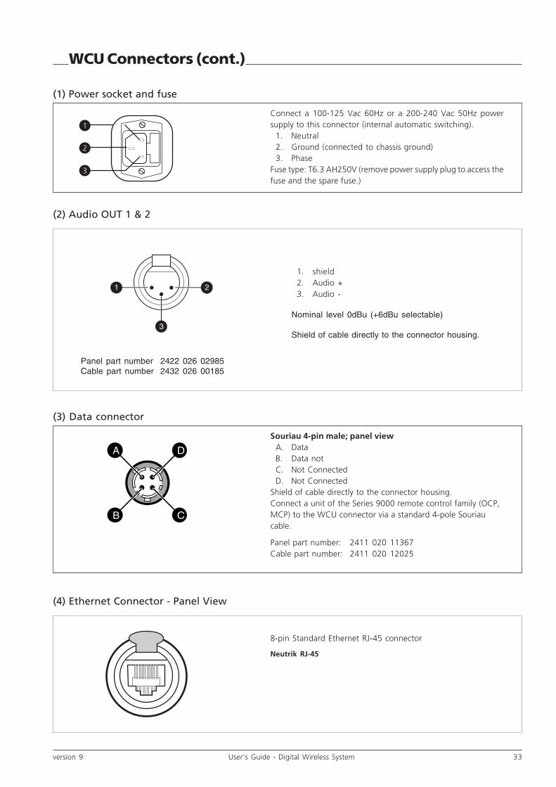
(1) Power socket and fuse
Connect a 100-125 Vac 60Hz or a 200-240 Vac 50Hz powersupply to this connector (internal automatic switching).
1. Neutral2. Ground (connected to chassis ground)3. Phase
Fuse type: T6.3 AH250V (remove power supply plug to access thefuse and the spare fuse.)
1
2
3
21
3
(2) Audio OUT 1 & 2
1. shield2. Audio +3. Audio -
Nominal level 0dBu (+6dBu selectable)
Shield of cable directly to the connector housing.
(4) Ethernet Connector - Panel View
8-pin Standard Ethernet RJ-45 connector
Neutrik RJ-45
Panel part number 2422 026 02985Cable part number 2432 026 00185
Souriau 4-pin male; panel viewA. DataB. Data notC. Not ConnectedD. Not Connected
Shield of cable directly to the connector housing.Connect a unit of the Series 9000 remote control family (OCP,MCP) to the WCU connector via a standard 4-pole Souriaucable.
Panel part number: 2411 020 11367Cable part number: 2411 020 12025
(3) Data connector
A
B C
D

34 User’s Guide - Digital Wireless System version 9
WCU Connectors (cont.)
(5) Reference input connectors
BNC connectorsThis BNC connector accepts a 1Vpp composite reference* signalto the camera for genlocking. (The second connector should beterminated with 75 Ohm if the signal is not looped through.)
* must have H and V sync. signals
(7) CVBS output connector
BNC connectorThis socket provides a 1Vpp CVBS output signal for monitoringpurposes.
(8) WCU SDI output connectors
BNC connectorsThese three BNC connectors provide a 0.8Vpp SDI output videosignal according to SMPTE 259M.
(6) Triax connector for AMU 1 & 2
Triax connectorThis socket is used to connect the triax cable (<400m of 8mm triaxcable) from the triax output of the AMU.
Receptacle types: Fischer, Tri-lock, ARD, Lemo 4, Lemo BBC,Lemo 3.

version 9 User’s Guide - Digital Wireless System 35
15-pin female, shielded cable
1. Prod. out (4-wire out, 2-wire in/out)2. Prod. in (4-wire only)3. Prod. in shield (4-wire only)4. ENG in (4-wire only)5. ENG out (4-wire out, 2-wire in/out)6. Progr. in (4-wire only)7. Progr. in shield (4-wire only)8. Housing9. prod. out return (4-wire out, 2-wire in/out)10. prod. in return (4-wire only)11. ENG in shield (4-wire only)12. ENG in return (4-wire only)13. ENG out return (4-wire out, 2-wire in/out)14. Progr. in return (4-wire only)15. Housing
Shield of cable to the pin marked housing.
15-pin female
Panel part number 2411 022 06239Cable part number 2411 022 05168
(9) Intercom Connector - Panel View
15 9
18
WCU Connectors (cont.)
2-wire:Nominal level 0dBuMinimum load impedance: 200 ohmMaximum DC level = 40 V
4-wire:Output signals:
nominal level 0dBu; impedance 600 ohm, symmetrical
Input signals:
level +6dBu or 0dBu selectable;impedance 10 Kohm (min), symmetrical
Housing
ENG in/out
PROD in/out
0dBuZ => 200 ohmMax 40V DC
15 8
91
(+)
(-)
(+)
(-)
Housing
PROG in
ENG in
PROD in
+6 dBu or 0dBuZin > 10 k ohms
ENG out
0dBZout < 600 ohms
15 8
91
PROD out

36 User’s Guide - Digital Wireless System version 9
91
158
15-pin male, shielded cable1. Prev. out ext. (relay contact < 10 ohm)2. Call out ext. (relay contact < 10 ohm)3. Iso in ext. (dry contact)4. On-Air in ext (dry contact)5. Call in ext. (dry contact)6. Audio 1 Input level *) Analogue input voltage 0V to
+5V, see figure below.- 64 dBu ------ 0V- 58 dBu ------ +0.7V- 52 dBu ------ +1.3V- 46 dBu ------ +1.9V- 40 dBu ------ +2.5V- 34 dBu ------ +3.1V- 28 dBu ------ +3.7V- 22 dBu ------ +4.3V
7. +5 Vdc; OCP8. Housing9. Prev. out ext. return10. Call out ext. return11. Iso in ext. return12. On-Air in ext. return13. Call in ext. return14. Audio 2 Input level *) see pin 615. GND*) Only when the External Gain Mode is set in the
Viewfinder Menu**) Shield of cable to the pin marked housing.
(11) Signalling Connector
15-pin male; panel view
Panel part number 2411 022 05292
Cable part number 2411 022 06157
158
19
Iso inOn Air in
Call in
GND
Audio 2 input sensitivity
-22dBu 1k
-28dBu 1k
-34dBu 1k
-40dBu 1k
-46dBu 1k
-52dBu 1k
-58dBu 1k
-64dBu 1k
Preview outCall out
+5V
Housing
WCU Connectors (cont.)

version 9 User’s Guide - Digital Wireless System 37
When the Iso, On-Air or Call signal isprovided by a dry contact, connect theoutputs to the signalling connector asshown in this figure.
When the Iso, On-Air or Call signalis provided by a dry contact with acommon return connector connectthe outputs to the signallingconnector as shown in this figure.
When the Iso, On-Air or Call signalis provided by a DC output voltageconnect the outputs to thesignalling connector as shown inthis figure.
Notes: The Iso, On-Air and Callsignal is off if the input voltage is5..24 VDC. The Iso, On-Air and Callsignal is on if the input voltage is0VDC. The X370 Signalling inputsare not galvanically separated. Werecommend using dry contacts andwhen these are not available usinggalvanically separated DC voltageoutputs.
Iso 1a
Iso 1b
Iso in ext. (PIN3)
Iso in ext. Return (PIN11)External Isosignalingdry contact
On-Air (Tally) 1a
On-Air (Tally) 1b
On-Air in ext. (PIN4)
On-Air in ext. Return (PIN12)External On-Airsignalingdry contact
Call 1a
Call 1b
Call in ext. (PIN5)
Call in ext. Return (PIN13)External Callsignalingdry contact
X 370 Signalling Connector
On-Air (Tally) 1
On-Air (Tally) 2
On-Air (Tally) n
Common
On-Air in ext. (PIN4) X 370 Signalling ConnectorBase Station 1
On-Air in ext. (PIN4) X 370 Signalling ConnectorBase Station 2
On-Air in ext. (PIN4) X 370 Signalling ConnectorBase Station n
On-Air in ext. Return (PIN12)
External On-Airsignaling withcommon contact
On-Air in ext. Return (PIN12)
On-Air in ext. Return (PIN12)
+5.24 VDC
ExternalOn-Airsignalingwith DCOutputVoltage
+
+5.24 VDC
ExternalCall signalingwith DCOutputVoltage
+
Iso 1a
+5.24 VDC
Iso 1b
Iso in ext. (PIN3)
Iso in ext. Return (PIN11)
ExternalIso signalingwith DCOutputVoltage
On-Air (Tally) 1a
On-Air (Tally) 1b
On-Air in ext. (PIN4)
On-Air in ext. Return (PIN12)
Call 1a
Call 1b
Call in ext. (PIN5)
Call in ext. Return (PIN13)
X 370 Signalling Connector
+
WCU Connectors (cont.)
38 User’s Guide - Digital Wireless System version 9
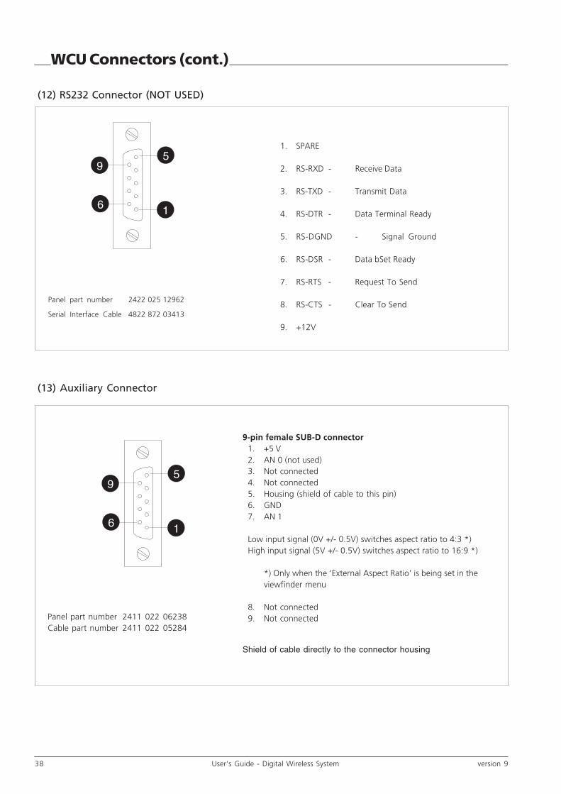
(13) Auxiliary Connector
1
95
6
9-pin female SUB-D connector1. +5 V2. AN 0 (not used)3. Not connected4. Not connected5. Housing (shield of cable to this pin)6. GND7. AN 1
Low input signal (0V +/- 0.5V) switches aspect ratio to 4:3 *)High input signal (5V +/- 0.5V) switches aspect ratio to 16:9 *)
*) Only when the ‘External Aspect Ratio’ is being set in theviewfinder menu
8. Not connected9. Not connected
Shield of cable directly to the connector housing
WCU Connectors (cont.)
(12) RS232 Connector (NOT USED)
1. SPARE
2. RS-RXD - Receive Data
3. RS-TXD - Transmit Data
4. RS-DTR - Data Terminal Ready
5. RS-DGND - Signal Ground
6. RS-DSR - Data bSet Ready
7. RS-RTS - Request To Send
8. RS-CTS - Clear To Send
9. +12V
Panel part number 2422 025 12962
Serial Interface Cable 4822 872 03413
1
95
6
Panel part number 2411 022 06238Cable part number 2411 022 05284

version 9 User’s Guide - Digital Wireless System 39
Specifications
Dimensions Adapter: 191mm x 120mm x 180mm (L x W x H)Camera head with adapter (without viewfinder):330mm x 120mm x 205mm (L x W x H)
Weight 2.2 kg (4.8 Kg incl. camera head and 1.5-inchviewfinder)
Operating temperature -20°C to +45°C
Storage temperature -20°C to +60°C
Power 12V DC, 42W including LDK 300 head and 1.5-inch VF
Battery plate Anton Bauer type
DC In 12V (11 to 17V); 3.5A (excluding DC Out); XLR 4
DC Out 11 to 17V (battery voltage) 1.5A; 6-pin Hirose
Video SDI monitoring quality output
VF signal B&W video 1.0 Vp-p, 75 Ohm output
Antennas RX antenna; BNC connector, RF signal input TXantenna; SMA connector, RF signal output
RF module COFDM DVB-T modulation in 2k mode
Frequency ranges 2.2 - 2.4 GHz, 2.4 - 2.5 Ghz or 2.5 - 2.7 Ghz dependingon module
Number of channels 16 per band
Emitted Power 15 dBm ± 1.5 dBm (conducted) for 2.4 - 2.5 Ghz band18 dBm ± 1.5 dBm (conducted) for all other bandsmeasured at 20°C ambient temperature
Bandwidth 7.8 MHz per channel (-3dB)
Bitrate 22 Mbit/s (wavelet compression)
Range 150m line-of-sight in open field conditions
Latency 1.5 Frame, NTSC 50mSec, Pal 60 mSec
Intercom Speech quality; latency to camera 250mSMicrophone level -44 to -24 dBu switchableInput impedance > 10 KOhmTelephone level +12 dBu nominalTelephone output impedance < 50 Ohm
Audio 1 channel full bandwidth (22 kHz, S/N 63dB typical) or2 channels reduced bandwidth (15 kHz, S/N 60dB typical)Input impedance > 10KOhmSensitivity range: -64 to -22 dBu or line (0dBu)
Tally out On: +5 Vdc CMOS level
External video 1 Vpp (C)VBS input
Wireless adapter unit
40 User’s Guide - Digital Wireless System version 9
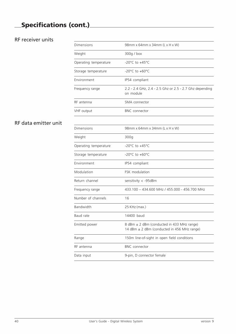
Specifications (cont.)
Dimensions 98mm x 64mm x 34mm (L x H x W)
Weight 300g / box
Operating temperature -20°C to +45°C
Storage temperature -20°C to +60°C
Environment IP54 compliant
Frequency range 2.2 - 2.4 GHz, 2.4 - 2.5 Ghz or 2.5 - 2.7 Ghz dependingon module
RF antenna SMA connector
VHF output BNC connector
Dimensions 98mm x 64mm x 34mm (L x H x W)
Weight 300g
Operating temperature -20°C to +45°C
Storage temperature -20°C to +60°C
Environment IP54 compliant
Modulation FSK modulation
Return channel sensitivity < -95dBm
Frequency range 433.100 – 434.600 MHz / 455.000 - 456.700 MHz
Number of channels 16
Bandwidth 25 KHz (max.)
Baud rate 14400 baud
Emitted power 8 dBm ± 2 dBm (conducted in 433 MHz range)14 dBm ± 2 dBm (conducted in 456 MHz range)
Range 150m line-of-sight in open field conditions
RF antenna BNC connector
Data input 9-pin, D connector female
RF receiver units
RF data emitter unit

version 9 User’s Guide - Digital Wireless System 41
Specifications (cont.)
These typical specifications are subject to change without notice.
Antenna managementunit (AMU)
Wireless control unit(WCU)
Dimensions 480mm x 250mm x 200mm (L x H x W)
Weight 8,5 Kg
Operating temperature -20°C to +45°C
Storage temperature -20°C to +60°C
Environment IP54 compliant
Data output 9-pin, D connector female
UHF inputs 3 x BNC connectors with active loop-through
TRIAX output Triax plug, towards WCU
Dimensions ½ 19-inch rack; 3U height
Weight 7 kg
Operating temperature 0°C to +45°C
Storage temperature -20°C to +60°C
Power 100-125 Vac 60Hz (3A) or 200-240 Vac 50Hz (1.5A)max. 150W depending on system configuration
Triax cable length 400m maximum with 8mm cable or600m maximum with 11mm cable
Video (x3) SDI x 3 SMPTE 259M; BNC
CVBS CVBS output monitoring quality; BNC
Genlock in B&B input with loop through; BNC
POWER in IEC type, 3 pin male
Intercom Speech qualityInput level 0 or +6 dBu selectableOutput level +6 dBu nominal (adjustable +/- 12dB per1.5 dB step
Audio Output level 0 or +6 dBu selectable
Applicable Standards EMC : EN 301489-3Radio: ETS 300 220; ETS 300 440Safety : EN60950

42 User’s Guide - Digital Wireless System version 9
Type numbers
Main type numbersLDK 5450/02 Wireless Camera AdapterLDK 4450/x1 *) Wireless Control UnitLDK 4452/x2 *) Antenna Management Unit **)
*) x=1: Fischer; x=2: Trilock; x=3: ARD; x=4: Lemo4; x=5: BBC Lemo; x=6: Lemo3**) includes: antenna bracket and 10m connecting cable set for connecting the AMU to the antenna set.
RF Video modulesLDK 5451/22 Camera RF Module 2.2-2.4GHz (incl. anternna)LDK 4453/22 Set (3 pcs.) RF Receiver Modules 2.2 - 2.4 GHz
LDK 5451/24 Camera RF Module 2.4-2.5GHz (incl. anternna)LDK 4453/24 Set (3 pcs.) RF Receiver Modules 2.4 - 2.5 GHz
LDK 5451/25 Camera RF Module 2.5-2.7GHz (incl. anternna)LDK 4453/25 Set (3 pcs.) RF Receiver Modules 2.5- 2.7 GHz
RF Data modulesLDK 4456/10 Camera RF Data Module 433 MHzLDK 4454/10 RF Data Emitter 433 MHz
LDK 4456/20 Camera RF Data Module 456 MHzLDK 4454/20 RF Data Emitter 456 MHz
AccessoriesThe lens, camera head, viewfinder, OCP, MCP, Triax cables and control cables are optional.
Mounting kits:
BDT05701AA Rack mount for one WCUBDT05700AA Coupling kit for two WCUs
Antenna booster units:
LDK 5455/10 COFDM Booster with Anton Bauer battery plateLDK 5455/20 COFDM Booster with IDX battery plateLDK 5455/30 COFDM Booster with PAG battery plate
LDK 4455/00 RF Data Booster

version 9 User’s Guide - Digital Wireless System 43
AntennaUp Convertor Module
Down Convertor (3x)
RxData Board V1
LDK 5451/22 Camera RF Module 2.2 - 2.4 GHz
LDK 5451/24 Camera RF Module 2.4 - 2.5 GHz
LDK 5451/25 Camera RF Module 2.5 - 2.7 GHz
LDK 4453/22 Set RF Receiver Modules 2.2 - 2.4 GHz
LDK 4453/24 Set RF Receiver Modules 2.4 - 2.5 GHz
LDK 4453/25 Set RF Receiver Modules 2.5 - 2.7 GHz
LDK 4456/10 Camera RF Data Module 433 MHz
LDK 4456/20 Camera RF Data Module 456 MHz
LDK 4454/10 RF Data Emitter 433 MHz
LDK 4454/20 RF Data Emitter 456 MHz
Antenna (3x)
Antenna Antenna
Return ChannelTransmitter board
Type numbers

44 User’s Guide - Digital Wireless System version 9