Embed Size (px)
Citation preview
WHITEPAPER
CMOS: Ready for Broadcast TodayKlaus Weber, Product Marketing Manager, Cameras
February 2012
While CCD is the current choice for imagers in today’s high-end broadcast cameras, CMOS imagers offer a great many advantages, including higher resolution and higher frame rates, especially as CCD technology reaches
its practical limits.
www.grassvalley.com
Contents
ii
CMOS: Ready fOR BROadCaSt tOday
www.grassvalley.com
Introduction 1
Why CMOS Now? 1
CCD Imager Requirements Based on Format 1
If CMOS is better than CCD, why is broadcast still CCD-based? 2
CMOS & CCD Comparisons 3
Figure 1 – Applications for Imagers 3
Figure 2 – Considerations for Imagers in 2012 3
Figure 3 – Structure of Imagers 4
Figure 4 – Scanning Methods 5
Figure 5 – Extreme Lighting 5
Figure 6 – Strobe Flash (Medium Intensity) 6
Figure 7 – Panning Shots in Typical Applications 7
Figure 8 – HD Format Switching 8
Figure 9 – Pixel Defects 8
Figure 10 – Operational Temperature 9
Figure 11 – Colorimetry 9
Figure 12 – Sensitivity 10
Figure 13 – The Future 10
Conclusion 11
Figure 14 – Conclusion 11
1
CMOS: Ready fOR BROadCaSt tOday
www.grassvalley.com
Introduction
Why CMOS Now?
Broadcast professionals are very familiar with CCD technology. It has been used successfully in broadcast cameras for many years. But today, CMOS technology is taking hold in broadcast.
CMOS broadcast technology is based on CMOS imagers having been used successfully in millions of mobile phones, and both consumer and professional digital cameras for years. In fact, today, all DSLR and all the latest single-chip 35 mm high-end digital cinematog-raphy cameras use CMOS imagers with an integrated color separator.
In 2007, Grass Valley™ introduced the Xensium™ CMOS imager, which today can be found in the LDK 3000+ high-performance multiformat HD camera. The three 2/3-inch CMOS imagers in the LDK 3000+ were specifi-cally developed for broadcast application with 2.4 million pixels (to natively switch between 720p and 1080i) and Double Digital Sampling (DDS), teamed with dual integrated A/D converters for high-quality, razor-sharp pictures.
The results achieved with this first generation of a dedicated broadcast CMOS imager clearly indicate that this is the technology which will replace broadcast CCD imagers in the future.
Simply, because now it’s better.
One of the main reasons that CCDs will be replaced by CMOS in broadcast applications is that CMOS imagers offer a number of advantages over CCDs, including higher resolution and higher frame rates.
To understand this point, one must look at how CCD and CMOS imagers read out images.
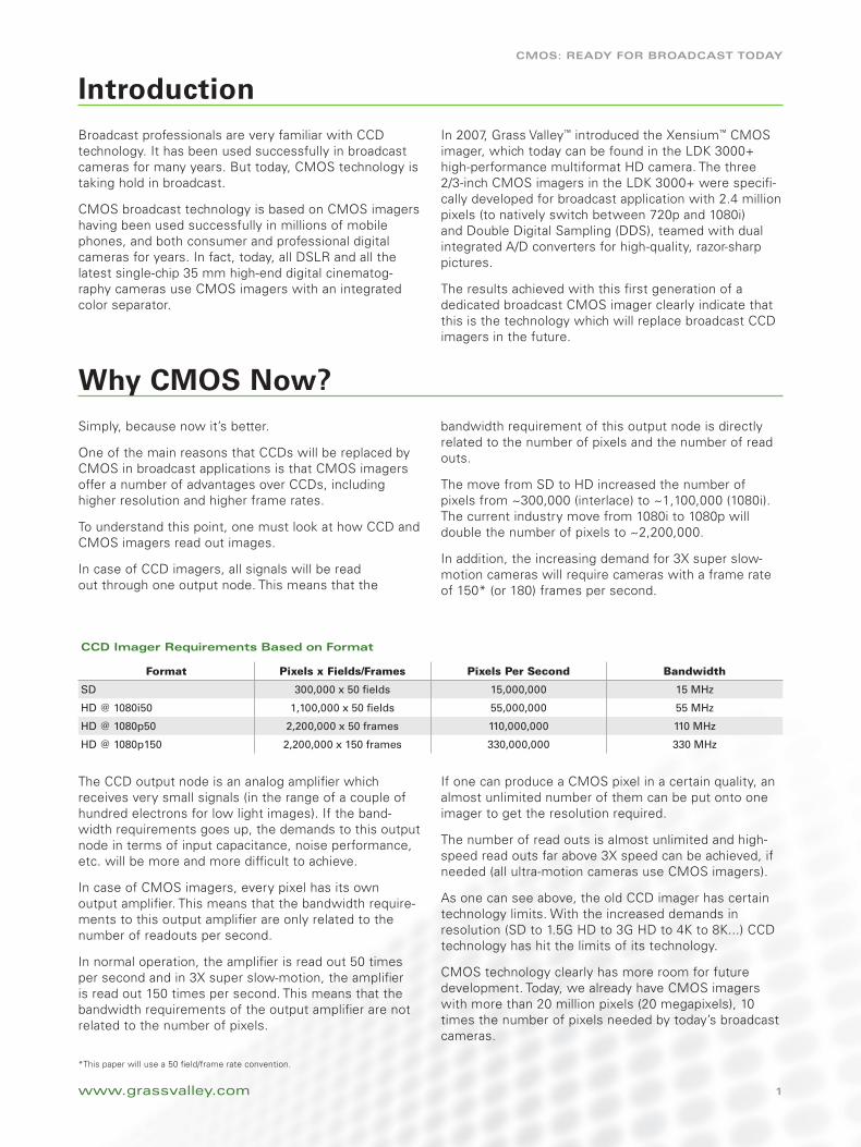
In case of CCD imagers, all signals will be read out through one output node. This means that the
bandwidth requirement of this output node is directly related to the number of pixels and the number of read outs.
The move from SD to HD increased the number of pixels from ~300,000 (interlace) to ~1,100,000 (1080i). The current industry move from 1080i to 1080p will double the number of pixels to ~2,200,000.
In addition, the increasing demand for 3X super slow-motion cameras will require cameras with a frame rate of 150* (or 180) frames per second.
The CCD output node is an analog amplifier which receives very small signals (in the range of a couple of hundred electrons for low light images). If the band-width requirements goes up, the demands to this output node in terms of input capacitance, noise performance, etc. will be more and more difficult to achieve.
In case of CMOS imagers, every pixel has its own output amplifier. This means that the bandwidth require-ments to this output amplifier are only related to the number of readouts per second.
In normal operation, the amplifier is read out 50 times per second and in 3X super slow-motion, the amplifier is read out 150 times per second. This means that the bandwidth requirements of the output amplifier are not related to the number of pixels.
If one can produce a CMOS pixel in a certain quality, an almost unlimited number of them can be put onto one imager to get the resolution required.
The number of read outs is almost unlimited and high-speed read outs far above 3X speed can be achieved, if needed (all ultra-motion cameras use CMOS imagers).
As one can see above, the old CCD imager has certain technology limits. With the increased demands in resolution (SD to 1.5G HD to 3G HD to 4K to 8K...) CCD technology has hit the limits of its technology.
CMOS technology clearly has more room for future development. Today, we already have CMOS imagers with more than 20 million pixels (20 megapixels), 10 times the number of pixels needed by today’s broadcast cameras.
Format Pixels x Fields/Frames Pixels Per Second Bandwidth
SD 300,000 x 50 fields 15,000,000 15 MHz
HD @ 1080i50 1,100,000 x 50 fields 55,000,000 55 MHz
HD @ 1080p50 2,200,000 x 50 frames 110,000,000 110 MHz
HD @ 1080p150 2,200,000 x 150 frames 330,000,000 330 MHz
CCd Imager Requirements Based on format
*This paper will use a 50 field/frame rate convention.
2
CMOS: Ready fOR BROadCaSt tOday
www.grassvalley.com
If CMOS is better than CCD, why is broadcast still CCD-based?
Even if today’s CCD technology does not offer much room for further developments, the CCD imagers avail-able provide a good enough solution for today’s broad-cast requirements. Since the development of a new camera imager is extremely expensive, it is undertaken only when clearly a new level of performance or new features can be achieved.
In any consumer or mass market application, every small advantage from new imager developments will pay off quickly. Therefore, the development cycles for consumer imagers are relatively short.
But broadcast cameras are a small volume application and the number of imagers needed for this application are only a few thousand units per year, for all camera manufactures combined. This means that once a new imager is developed for the very specific demands of broadcast, this imager will be produced for several years.
The suppliers of broadcast CCD imagers want to sell their current imagers as long as they can, and they do not like to invest in new imaging technology as long as they are not forced to do so.
For today’s broadcast application requirements, the current CCD imager still offers a good enough solu-tion. But even if the current CCD imagers offer a good enough solution for today’s broadcast applica-tion requirements, the latest improvements in CMOS imagers clearly show the advantages of that technology: such as full digital imaging technology, low power consumption, low heat, etc. Based on the evidence given above, it can be expected that all of the future camera imagers for broadcast applications will be CMOS-based.
3
CMOS: Ready fOR BROadCaSt tOday
www.grassvalley.com
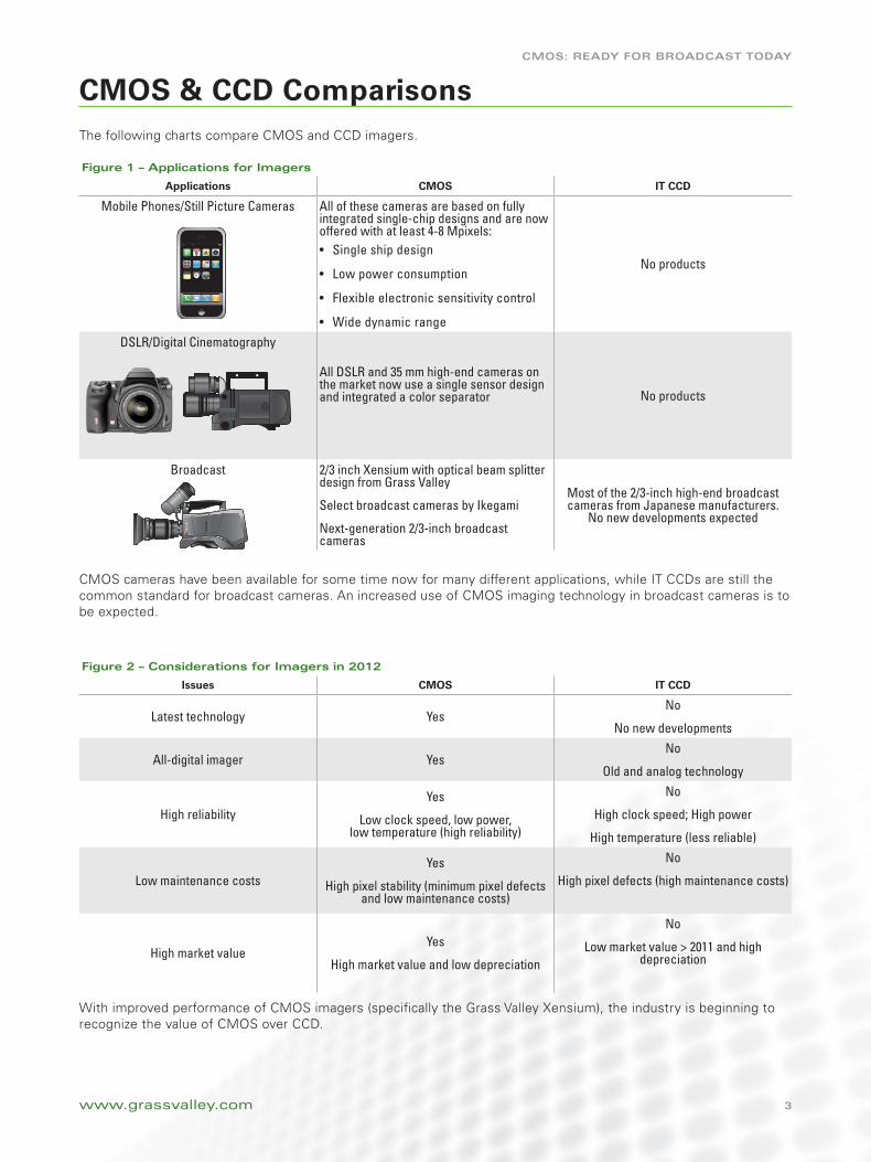
CMOS & CCD ComparisonsThe following charts compare CMOS and CCD imagers.
figure 1 – applications for Imagers
Applications CMOS IT CCD
Mobile Phones/Still Picture Cameras All of these cameras are based on fully integrated single-chip designs and are now offered with at least 4-8 Mpixels:
Single ship design•
Low power consumption•
Flexible electronic sensitivity control•
Wide dynamic range•
No products
DSLR/Digital Cinematography
All DSLR and 35 mm high-end cameras on the market now use a single sensor design and integrated a color separator No products
Broadcast 2/3 inch Xensium with optical beam splitter design from Grass Valley
Select broadcast cameras by Ikegami
Next-generation 2/3-inch broadcast cameras
Most of the 2/3-inch high-end broadcast cameras from Japanese manufacturers.
No new developments expected
CMOS cameras have been available for some time now for many different applications, while IT CCDs are still the common standard for broadcast cameras. An increased use of CMOS imaging technology in broadcast cameras is to be expected.
figure 2 – Considerations for Imagers in 2012
Issues CMOS IT CCD
Latest technology YesNo
No new developments
All-digital imager YesNo
Old and analog technology
High reliabilityYes
Low clock speed, low power, low temperature (high reliability)
No
High clock speed; High power
High temperature (less reliable)
Low maintenance costsYes
High pixel stability (minimum pixel defects and low maintenance costs)
No
High pixel defects (high maintenance costs)
High market valueYes
High market value and low depreciation
No
Low market value > 2011 and high depreciation
With improved performance of CMOS imagers (specifically the Grass Valley Xensium), the industry is beginning to recognize the value of CMOS over CCD.
4
CMOS: Ready fOR BROadCaSt tOday
CMOS & CCD Comparisons (cont.)
www.grassvalley.com
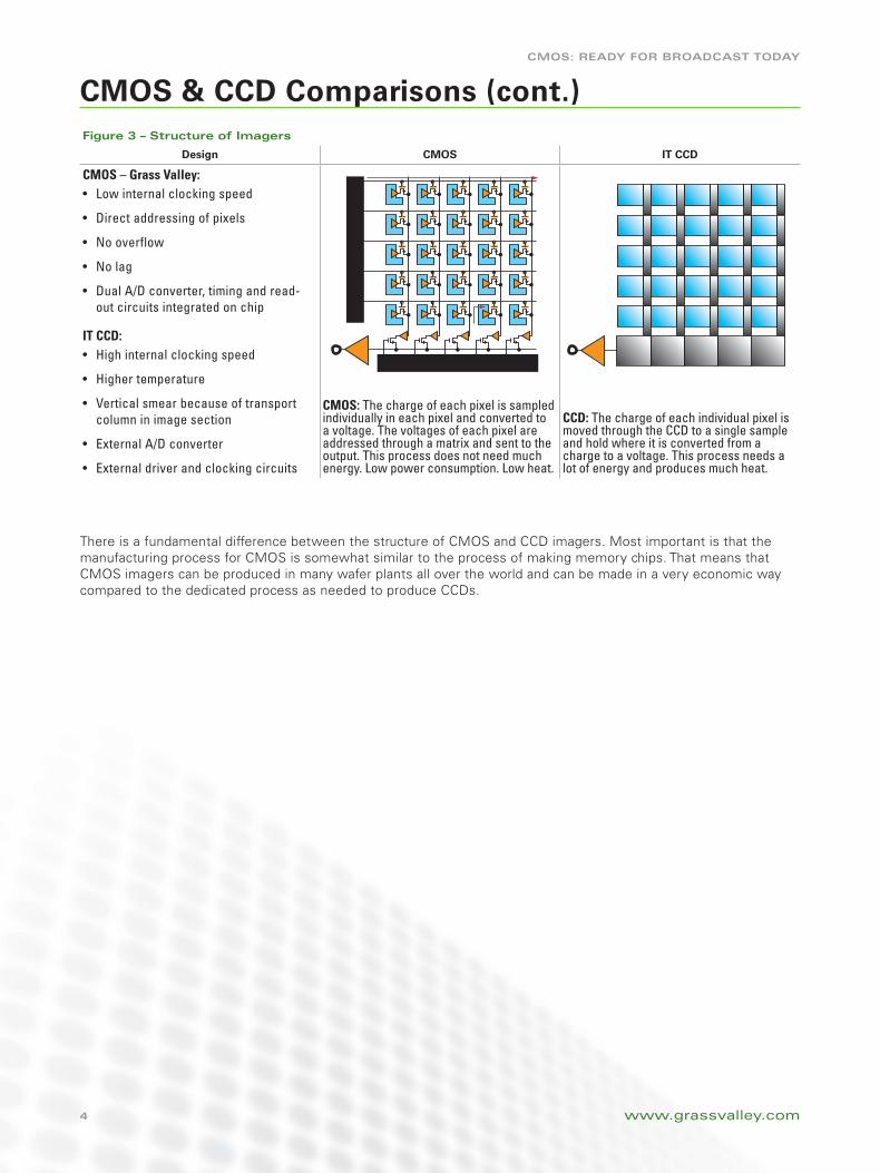
figure 3 – Structure of Imagers
Design CMOS IT CCD
CMOS – Grass Valley:Low internal clocking speed•
Direct addressing of pixels •
No overflow•
No lag•
Dual A/D converter, timing and read-•out circuits integrated on chip
IT CCD:High internal clocking speed•
Higher temperature •
Vertical smear because of transport •column in image section
External A/D converter•
External driver and clocking circuits•
CMOS: The charge of each pixel is sampled individually in each pixel and converted to a voltage. The voltages of each pixel are addressed through a matrix and sent to the output. This process does not need much energy. Low power consumption. Low heat.
CCD: The charge of each individual pixel is moved through the CCD to a single sample and hold where it is converted from a charge to a voltage. This process needs a lot of energy and produces much heat.
There is a fundamental difference between the structure of CMOS and CCD imagers. Most important is that the manufacturing process for CMOS is somewhat similar to the process of making memory chips. That means that CMOS imagers can be produced in many wafer plants all over the world and can be made in a very economic way compared to the dedicated process as needed to produce CCDs.
5
CMOS: Ready fOR BROadCaSt tOday
CMOS & CCD Comparisons (cont.)
www.grassvalley.com
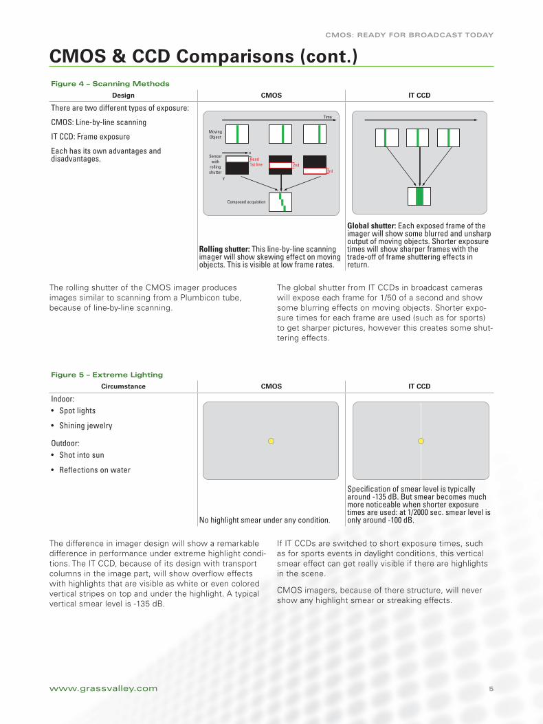
figure 4 – Scanning Methods
Design CMOS IT CCD
There are two different types of exposure:
CMOS: Line-by-line scanning
IT CCD: Frame exposure
Each has its own advantages and disadvantages.
Rolling shutter: This line-by-line scanning imager will show skewing effect on moving objects. This is visible at low frame rates.
Global shutter: Each exposed frame of the imager will show some blurred and unsharp output of moving objects. Shorter exposure times will show sharper frames with the trade-off of frame shuttering effects in return.
figure 5 – extreme Lighting
Circumstance CMOS IT CCD
Indoor: Spot lights •
Shining jewelry•
Outdoor: Shot into sun•
Reflections on water•
No highlight smear under any condition.
Specification of smear level is typically around -135 dB. But smear becomes much more noticeable when shorter exposure times are used: at 1/2000 sec. smear level is only around -100 dB.
MovingObject
Sensorwith
rollingshutter
Composed acquistion
Read 1st line 2nd
x
y3rd
Time
The rolling shutter of the CMOS imager produces images similar to scanning from a Plumbicon tube, because of line-by-line scanning.
The global shutter from IT CCDs in broadcast cameras will expose each frame for 1/50 of a second and show some blurring effects on moving objects. Shorter expo-sure times for each frame are used (such as for sports) to get sharper pictures, however this creates some shut-tering effects.
The difference in imager design will show a remarkable difference in performance under extreme highlight condi-tions. The IT CCD, because of its design with transport columns in the image part, will show overflow effects with highlights that are visible as white or even colored vertical stripes on top and under the highlight. A typical vertical smear level is -135 dB.
If IT CCDs are switched to short exposure times, such as for sports events in daylight conditions, this vertical smear effect can get really visible if there are highlights in the scene.
CMOS imagers, because of there structure, will never show any highlight smear or streaking effects.
6
CMOS: Ready fOR BROadCaSt tOday
CMOS & CCD Comparisons (cont.)
www.grassvalley.com
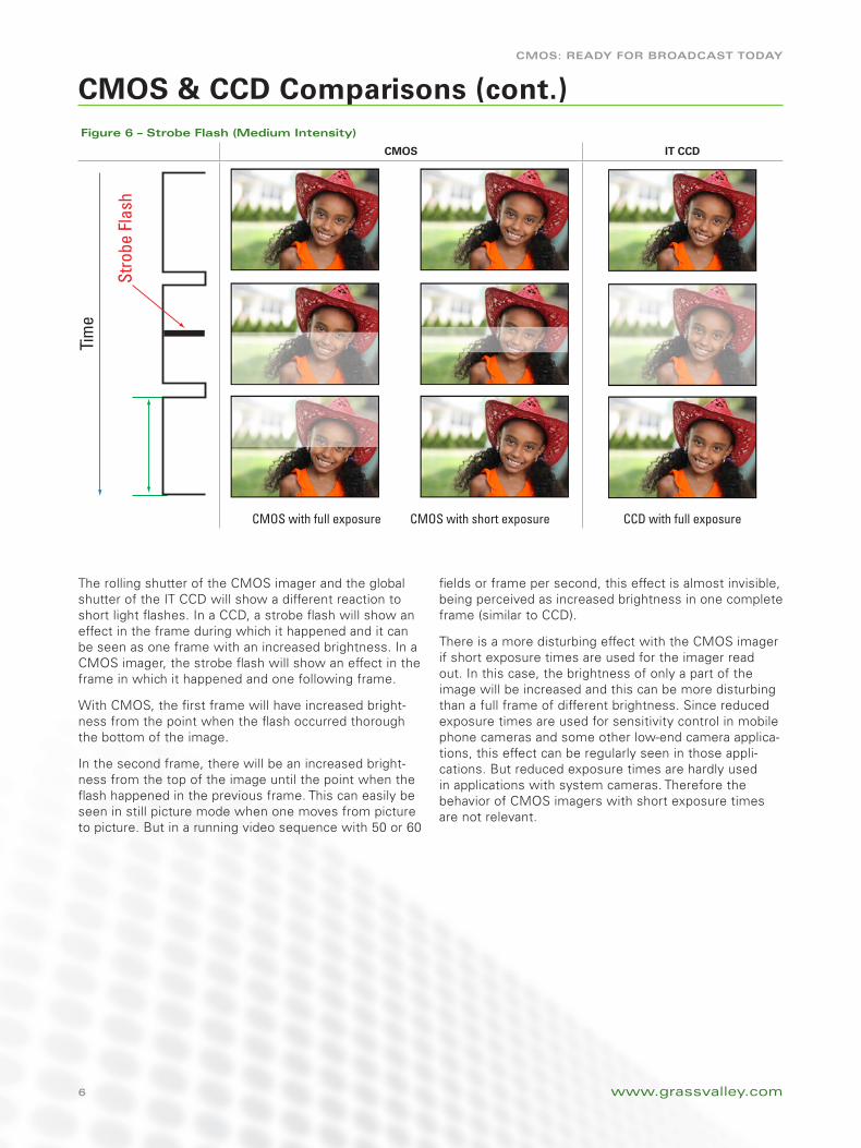
figure 6 – Strobe flash (Medium Intensity)
CMOS IT CCD
CMOS with full exposure CMOS with short exposure CCD with full exposure
Tim
e
Stro
be F
lash
The rolling shutter of the CMOS imager and the global shutter of the IT CCD will show a different reaction to short light flashes. In a CCD, a strobe flash will show an effect in the frame during which it happened and it can be seen as one frame with an increased brightness. In a CMOS imager, the strobe flash will show an effect in the frame in which it happened and one following frame.
With CMOS, the first frame will have increased bright-ness from the point when the flash occurred thorough the bottom of the image.
In the second frame, there will be an increased bright-ness from the top of the image until the point when the flash happened in the previous frame. This can easily be seen in still picture mode when one moves from picture to picture. But in a running video sequence with 50 or 60
fields or frame per second, this effect is almost invisible, being perceived as increased brightness in one complete frame (similar to CCD).
There is a more disturbing effect with the CMOS imager if short exposure times are used for the imager read out. In this case, the brightness of only a part of the image will be increased and this can be more disturbing than a full frame of different brightness. Since reduced exposure times are used for sensitivity control in mobile phone cameras and some other low-end camera applica-tions, this effect can be regularly seen in those appli-cations. But reduced exposure times are hardly used in applications with system cameras. Therefore the behavior of CMOS imagers with short exposure times are not relevant.
7
CMOS: Ready fOR BROadCaSt tOday
CMOS & CCD Comparisons (cont.)
www.grassvalley.com
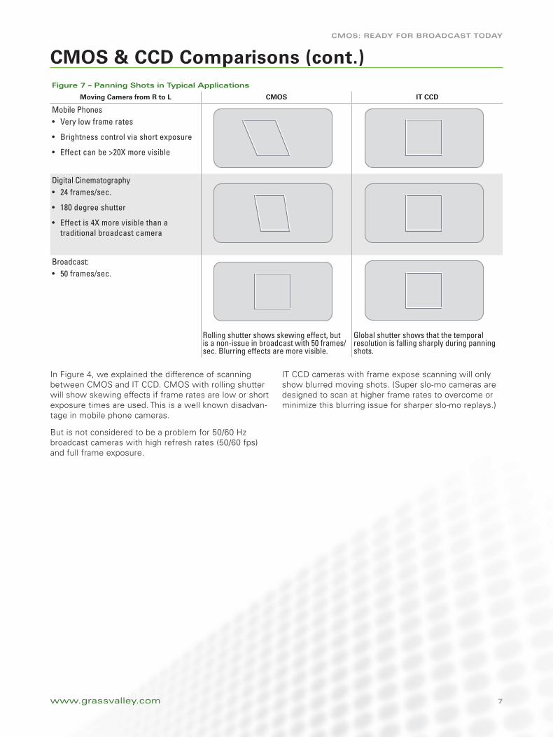
figure 7 – Panning Shots in typical applications
Moving Camera from R to L CMOS IT CCD
Mobile PhonesVery low frame rates•
Brightness control via short exposure •
Effect can be >20X more visible•
Digital Cinematography24 frames/sec.•
180 degree shutter•
Effect is 4X more visible than a •traditional broadcast camera
Broadcast:50 frames/sec.•
Rolling shutter shows skewing effect, but is a non-issue in broadcast with 50 frames/sec. Blurring effects are more visible.
Global shutter shows that the temporal resolution is falling sharply during panning shots.
In Figure 4, we explained the difference of scanning between CMOS and IT CCD. CMOS with rolling shutter will show skewing effects if frame rates are low or short exposure times are used. This is a well known disadvan-tage in mobile phone cameras.
But is not considered to be a problem for 50/60 Hz broadcast cameras with high refresh rates (50/60 fps) and full frame exposure.
IT CCD cameras with frame expose scanning will only show blurred moving shots. (Super slo-mo cameras are designed to scan at higher frame rates to overcome or minimize this blurring issue for sharper slo-mo replays.)
8
CMOS: Ready fOR BROadCaSt tOday
CMOS & CCD Comparisons (cont.)
www.grassvalley.com
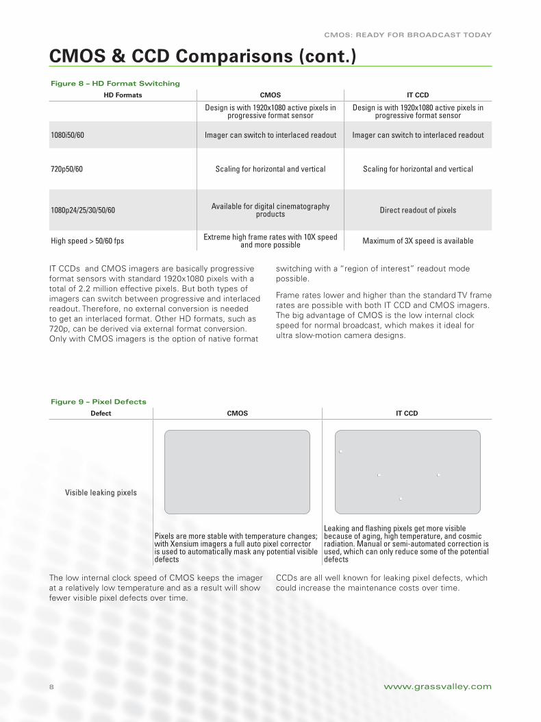
figure 8 – Hd format Switching
HD Formats CMOS IT CCD
Design is with 1920x1080 active pixels in progressive format sensor
Design is with 1920x1080 active pixels in progressive format sensor
1080i50/60 Imager can switch to interlaced readout Imager can switch to interlaced readout
720p50/60 Scaling for horizontal and vertical Scaling for horizontal and vertical
1080p24/25/30/50/60 Available for digital cinematography products Direct readout of pixels
High speed > 50/60 fps Extreme high frame rates with 10X speed and more possible Maximum of 3X speed is available
IT CCDs and CMOS imagers are basically progressive format sensors with standard 1920x1080 pixels with a total of 2.2 million effective pixels. But both types of imagers can switch between progressive and interlaced readout. Therefore, no external conversion is needed to get an interlaced format. Other HD formats, such as 720p, can be derived via external format conversion. Only with CMOS imagers is the option of native format
switching with a “region of interest” readout mode possible.
Frame rates lower and higher than the standard TV frame rates are possible with both IT CCD and CMOS imagers. The big advantage of CMOS is the low internal clock speed for normal broadcast, which makes it ideal for ultra slow-motion camera designs.
The low internal clock speed of CMOS keeps the imager at a relatively low temperature and as a result will show fewer visible pixel defects over time.
CCDs are all well known for leaking pixel defects, which could increase the maintenance costs over time.
figure 9 – Pixel defects
Defect CMOS IT CCD
Visible leaking pixels
Pixels are more stable with temperature changes; with Xensium imagers a full auto pixel corrector is used to automatically mask any potential visible defects
Leaking and flashing pixels get more visible because of aging, high temperature, and cosmic radiation. Manual or semi-automated correction is used, which can only reduce some of the potential defects
9
CMOS: Ready fOR BROadCaSt tOday
CMOS & CCD Comparisons (cont.)
www.grassvalley.com
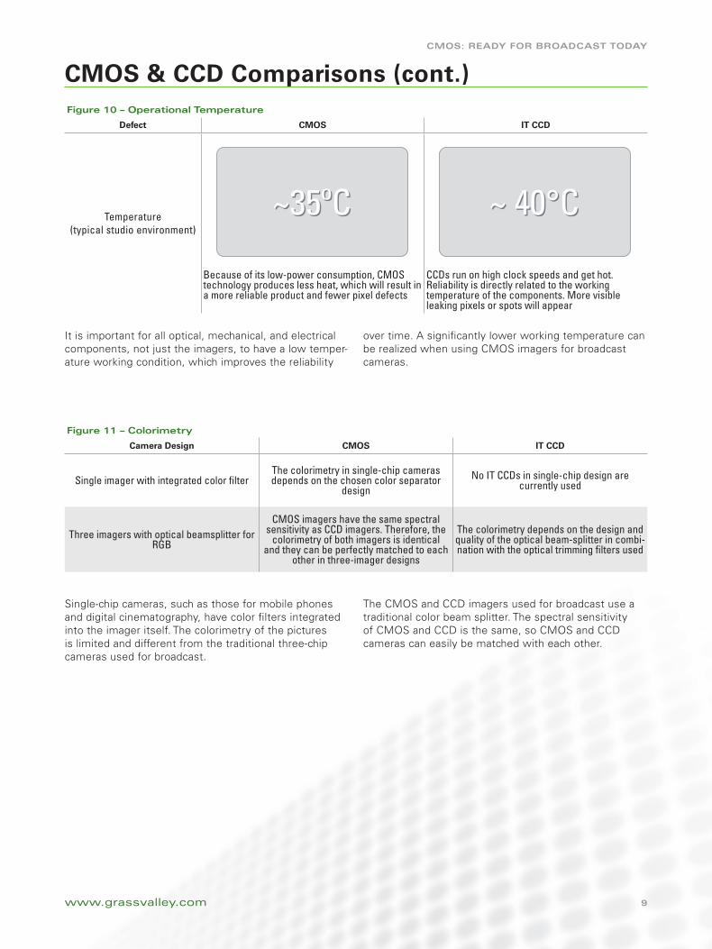
It is important for all optical, mechanical, and electrical components, not just the imagers, to have a low temper-ature working condition, which improves the reliability
over time. A significantly lower working temperature can be realized when using CMOS imagers for broadcast cameras.
Single-chip cameras, such as those for mobile phones and digital cinematography, have color filters integrated into the imager itself. The colorimetry of the pictures is limited and different from the traditional three-chip cameras used for broadcast.
The CMOS and CCD imagers used for broadcast use a traditional color beam splitter. The spectral sensitivity of CMOS and CCD is the same, so CMOS and CCD cameras can easily be matched with each other.
figure 10 – Operational temperature
Defect CMOS IT CCD
Temperature (typical studio environment)
Because of its low-power consumption, CMOS technology produces less heat, which will result in a more reliable product and fewer pixel defects
CCDs run on high clock speeds and get hot. Reliability is directly related to the working temperature of the components. More visible leaking pixels or spots will appear
figure 11 – Colorimetry
Camera Design CMOS IT CCD
Single imager with integrated color filterThe colorimetry in single-chip cameras depends on the chosen color separator
designNo IT CCDs in single-chip design are
currently used
Three imagers with optical beamsplitter for RGB
CMOS imagers have the same spectral sensitivity as CCD imagers. Therefore, the
colorimetry of both imagers is identical and they can be perfectly matched to each
other in three-imager designs
The colorimetry depends on the design and quality of the optical beam-splitter in combi-nation with the optical trimming filters used
~35ºC~35ºC ~ 40°C~ 40°C
10
CMOS: Ready fOR BROadCaSt tOday
www.grassvalley.com
CMOS & CCD Comparisons (cont.)
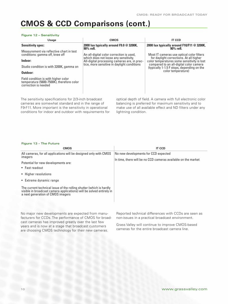
The sensitivity specifications for 2/3-inch broadcast cameras are somewhat standard and in the range of F9-F11. More important is the sensitivity in operational conditions for indoor and outdoor with requirements for
optical depth of field. A camera with full electronic color balancing is preferred for maximum sensitivity and to make use of all available effect and ND filters under any lightning condition.
No major new developments are expected from manu-facturers for CCDs. The performance of CMOS for broad-cast cameras has improved greatly over the last few years and is now at a stage that broadcast customers are choosing CMOS technology for their new cameras.
Reported technical differences with CCDs are seen as non-issues in a practical broadcast environment.
Grass Valley will continue to improve CMOS-based cameras for the entire broadcast camera line.
figure 12 – Sensitivity
Usage CMOS IT CCD
Sensitivity spec:
Measurement via reflective chart in test conditions: gamma off, knee off
Indoor:
Studio condition is with 3200K, gamma on
Outdoor:
Field condition is with higher color temperature (5600-7500K), therefore color correction is needed
2000 lux typically around F9.0 @ 3200K, 90% refl.
An all-digital color correction is used, which does not loose any sensitivity. All-digital processing cameras are, in prac-tice, more sensitive in daylight conditions
2000 lux typically around F10/F11 @ 3200K, 90% refl.
Most IT cameras use optical color filters for daylight corrections. At all higher
color temperatures some sensitivity is lost compared to an all-digital color camera (typically 1-1.5 F stops, depending on the
color temperature)
figure 13 – the future
CMOS IT CCD
All cameras, for all applications will be designed only with CMOS imagers
Potential for new developments are:Fast readout•
Higher resolutions•
Extreme dynamic range•
The current technical issue of the rolling shutter (which is hardly visible in broadcast camera applications) will be solved entirely in a next generation of CMOS imagers
No new developments for CCD expected
In time, there will be no CCD cameras available on the market
CMOS: Ready fOR BROadCaSt tOday
© Copyright 2012 Grass Valley USA, LLC. All rights reserved. Grass Valley and Xensium are trademarks of GVBB Holdings S.a.r.l. All other tradenames referenced are service marks, trademarks, or registered trademarks of their respective companies. Specifications subject to change without notice. CAM-4073M
Grass Valley Global Services specializes in the defining of, deployment of, and support of today’s dynamic file-based workflows, based on Grass Valley and third-party solutions. With Grass Valley Global Services, you can achieve your operational goals in the most efficient and cost-effective way possible with a partner you can trust.
www.grassvalley.com/support
Define: We help you to define your business and technology requirements and then design solutions to meet them. Deploy: Our professional service organization, backed up with proven project management methodologies, can take you from design through deployment, commissioning, and training.Support: We offer a complete Support Agreement portfolio to keep your systems running and help plan for your long-term maintenance needs.
Join the Conversation at GrassValleyLive on Facebook,
Twitter, and YouTube.
GLOBaL SeRvICeS
ConclusionAlthough CCD imagers are today’s standard for broadcast television production, they have reached the end of their lifecycle, with no new technological developments planned. CMOS imagers, while fairly a new development in broadcast camera design, have been used for years in millions of consumer, prosumer, and professional cameras.
The performance characteristics of CMOS when compared to CCD is outstanding, delivering far more benefits to the user. But the real benefit is the picture. CMOS imagers produce the same or better quality of picture as today’s CCDs.
When looking at the benefits of CMOS over CCD, those looking for new broadcast cameras must justify buying older CCD-based technology since the current performance of CMOS is ready and proven for broadcast, future-proof, and available today.