Embed Size (px)
Citation preview

USER’S GUIDE
Ethernet Power Controller 5
Ethernet Power Controller 5 digital-loggers.com2
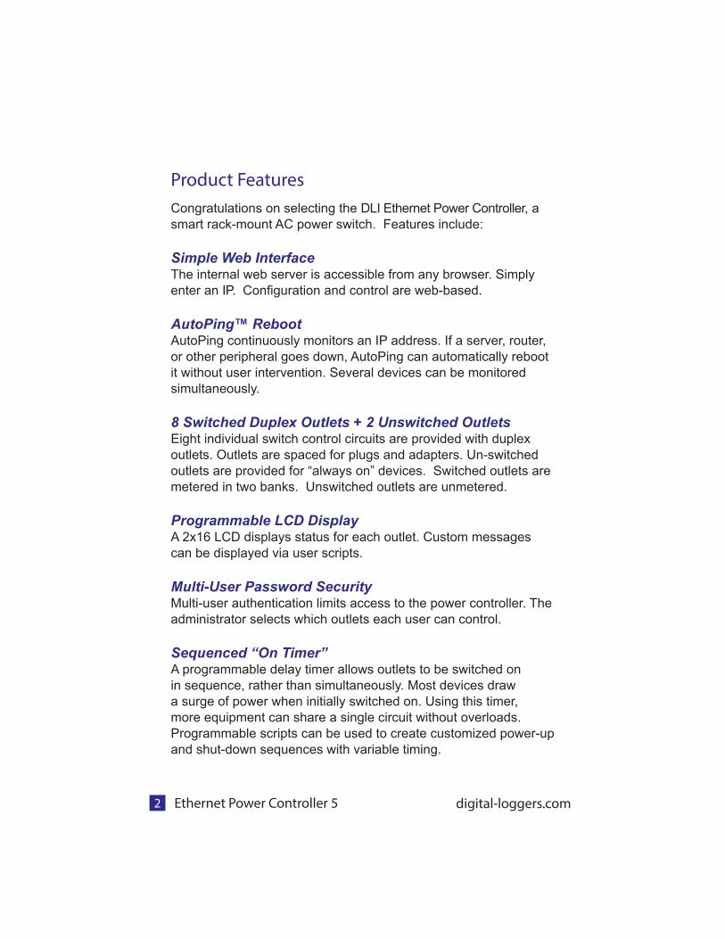
Product Features
Congratulations on selecting the DLI Ethernet Power Controller, a
smart rack-mount AC power switch. Features include:
Simple Web InterfaceThe internal web server is accessible from any browser. Simply
enter an IP. Confi guration and control are web-based.
AutoPing™ RebootAutoPing continuously monitors an IP address. If a server, router,
or other peripheral goes down, AutoPing can automatically reboot
it without user intervention. Several devices can be monitored
simultaneously.
8 Switched Duplex Outlets + 2 Unswitched OutletsEight individual switch control circuits are provided with duplex
outlets. Outlets are spaced for plugs and adapters. Un-switched
outlets are provided for “always on” devices. Switched outlets are
metered in two banks. Unswitched outlets are unmetered.
Programmable LCD DisplayA 2x16 LCD displays status for each outlet. Custom messages
can be displayed via user scripts.
Multi-User Password SecurityMulti-user authentication limits access to the power controller. The
administrator selects which outlets each user can control.
Sequenced “On Timer”A programmable delay timer allows outlets to be switched on
in sequence, rather than simultaneously. Most devices draw
a surge of power when initially switched on. Using this timer,
more equipment can share a single circuit without overloads.
Programmable scripts can be used to create customized power-up
and shut-down sequences with variable timing.

Ethernet Power Controller 5 3
MOV Surge SuppressionDual 3600W metal oxide varistors clamp power surges and
spikes, protecting attached devices.
Scripting Language, Syslog, and UtilitiesLua scripting can be used to create custom control and reboot
sequences, schedule periodic reboots, etc. Internal and external
event logs are provided.
New FeaturesNew features include Email, SNMP and Jabber notifi cation,
improved power metering, a light sensor, internal temperature
sensor, longer battery life, HTTPS, WiFi support, web power
meters/charts and Lua scripting.
Field Upgradeable FirmwareFirmware is fi eld upgradeable via Ethernet.
Package Contents
• Ethernet Power Controller 5 with NEMA 5-15 plugs and
reversable rack ears attached.
• RP-SMA WiFi Antenna
• Internal web server backup battery (shipped disconnected)
Please contact the freight carrier immediately if your package
appears opened or damaged in transit. Call DLI at (408) 330-5599
for tech support, service, and hardware upgrades.
Ethernet Power Controller 5 digital-loggers.com4
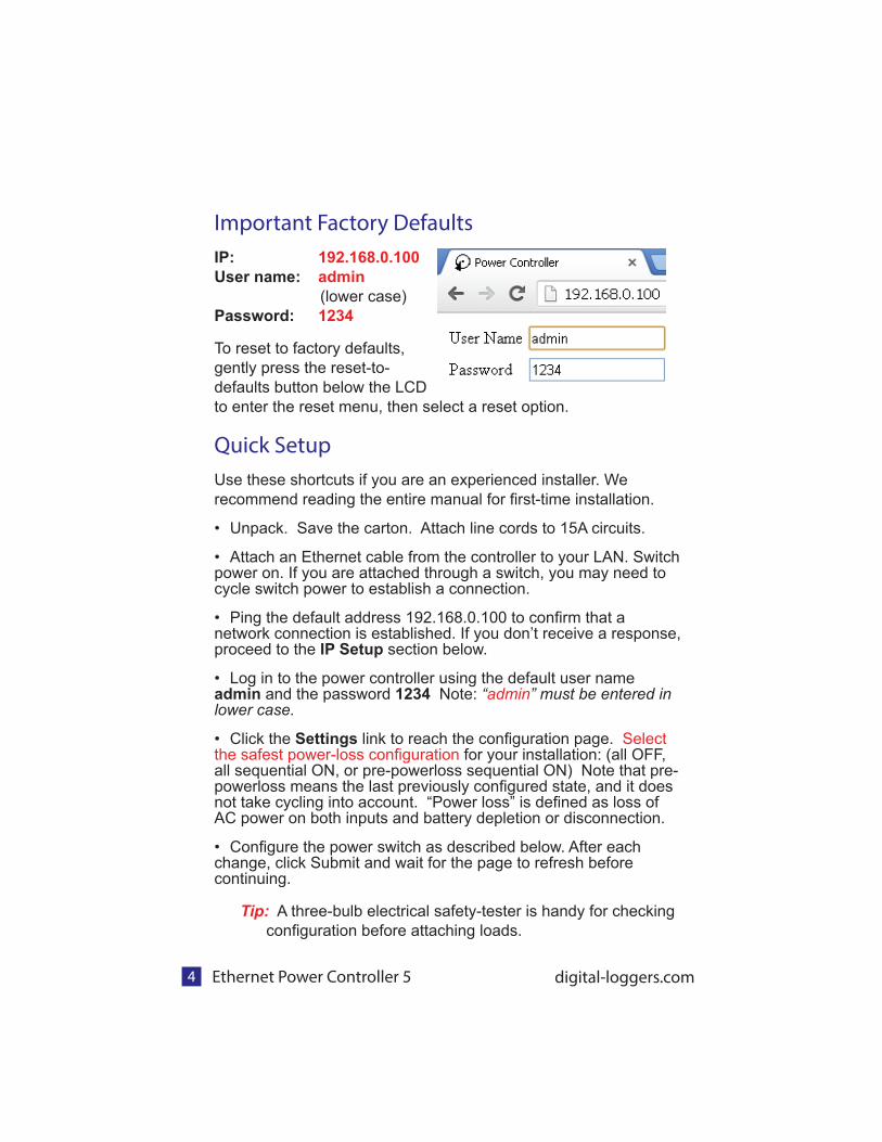
Important Factory Defaults
IP: 192.168.0.100
User name: admin
(lower case)
Password: 1234
To reset to factory defaults,
gently press the reset-to-
defaults button below the LCD
to enter the reset menu, then select a reset option.
Quick Setup
Use these shortcuts if you are an experienced installer. We
recommend reading the entire manual for fi rst-time installation.
• Unpack. Save the carton. Attach line cords to 15A circuits.
• Attach an Ethernet cable from the controller to your LAN. Switch power on. If you are attached through a switch, you may need to cycle switch power to establish a connection.
• Ping the default address 192.168.0.100 to confi rm that a network connection is established. If you don’t receive a response, proceed to the IP Setup section below.
• Log in to the power controller using the default user name admin and the password 1234 Note: “admin” must be entered in lower case.
• Click the Settings link to reach the confi guration page. Select the safest power-loss confi guration for your installation: (all OFF, all sequential ON, or pre-powerloss sequential ON) Note that pre-powerloss means the last previously confi gured state, and it does not take cycling into account. “Power loss” is defi ned as loss of AC power on both inputs and battery depletion or disconnection.
• Confi gure the power switch as described below. After each change, click Submit and wait for the page to refresh before continuing.
Tip: A three-bulb electrical safety-tester is handy for checking
confi guration before attaching loads.

Ethernet Power Controller 5 5
IP Setup
If your network settings won’t access the default IP, use a direct
cable connection (temporarily bypass any switch or router)
and follow these steps to add a compatible static IP, such as
192.168.0.50 Before adding an IP, close all programs and
browsers. After the link is established, you can enable DHCP.
Windows Step 1
In Windows, the fi rst step is locating the network adapter TCP/IP
properties. The procedure differs for each Windows version:
Windows XP, 2000, 2003: Open Start / Control Panel / Network
Connections. In “classic view”, select Start / Settings / Control
Panel /Network Connections. Right-click on Local Area
Network Connection and select Properties. Proceed to step 2.
Windows Vista: Open Start, right click on Network, then on
Properties. Double click Network and Sharing Center, click
Manage Newtork Connections. A Network Connections window
appears. Right click on the network connection to the switch, ie.
Local Area Network. Proceed to step 2.
Windows 7: Open the Start orb, click on Control Panel. Click
View Network Status and Tasks, then Change Adapter
Settings. Proceed to step 2
Windows 8-10: Mouse or swipe to the bottom right corner and
select Settings. Select Control Panel. Select Network and
Sharing Center or Network->Network Settings. Click change
Adapter Settings or Adapter Options. Right click on your
connected network and select Properties. Proceed to step 2
Windows Step 2
The second step is adding an IP such as 192.168.0.50
Temporarily disable DHCP while confi guring the switch.
Web Power Switch 7 digital-loggers.com6
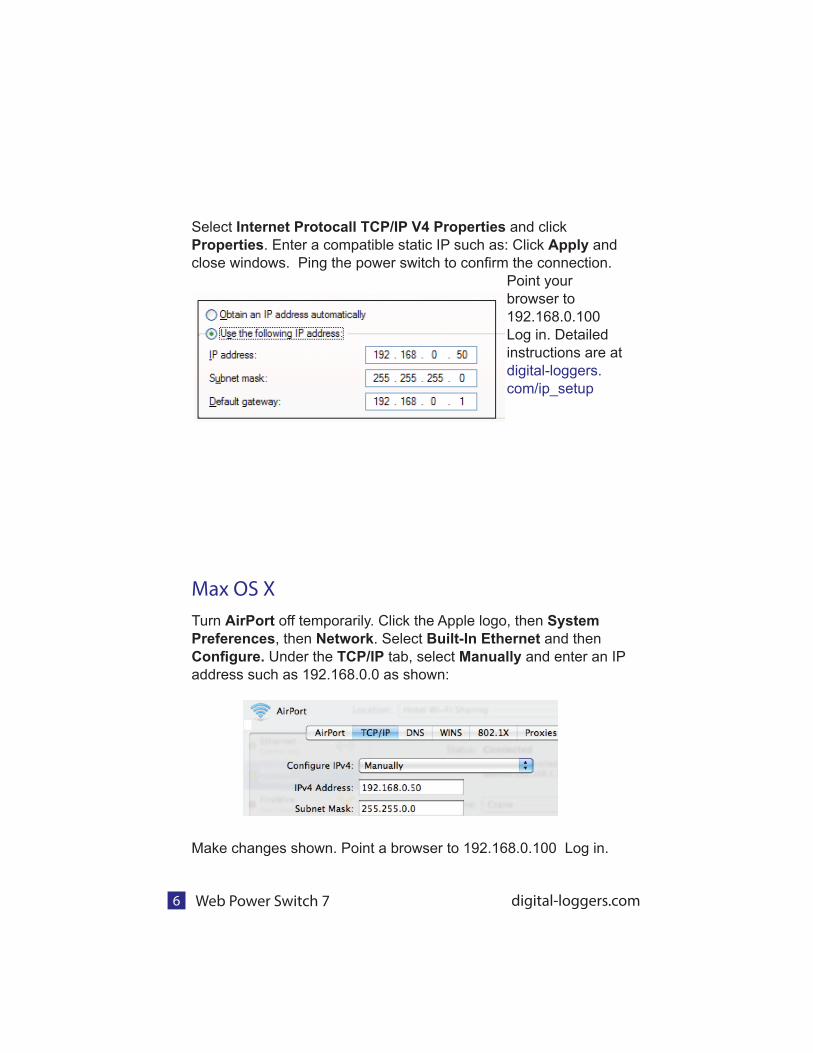
Select Internet Protocall TCP/IP V4 Properties and click
Properties. Enter a compatible static IP such as: Click Apply and
close windows. Ping the power switch to confi rm the connection.
Point your
browser to
192.168.0.100
Log in. Detailed
instructions are at
digital-loggers.
com/ip_setup
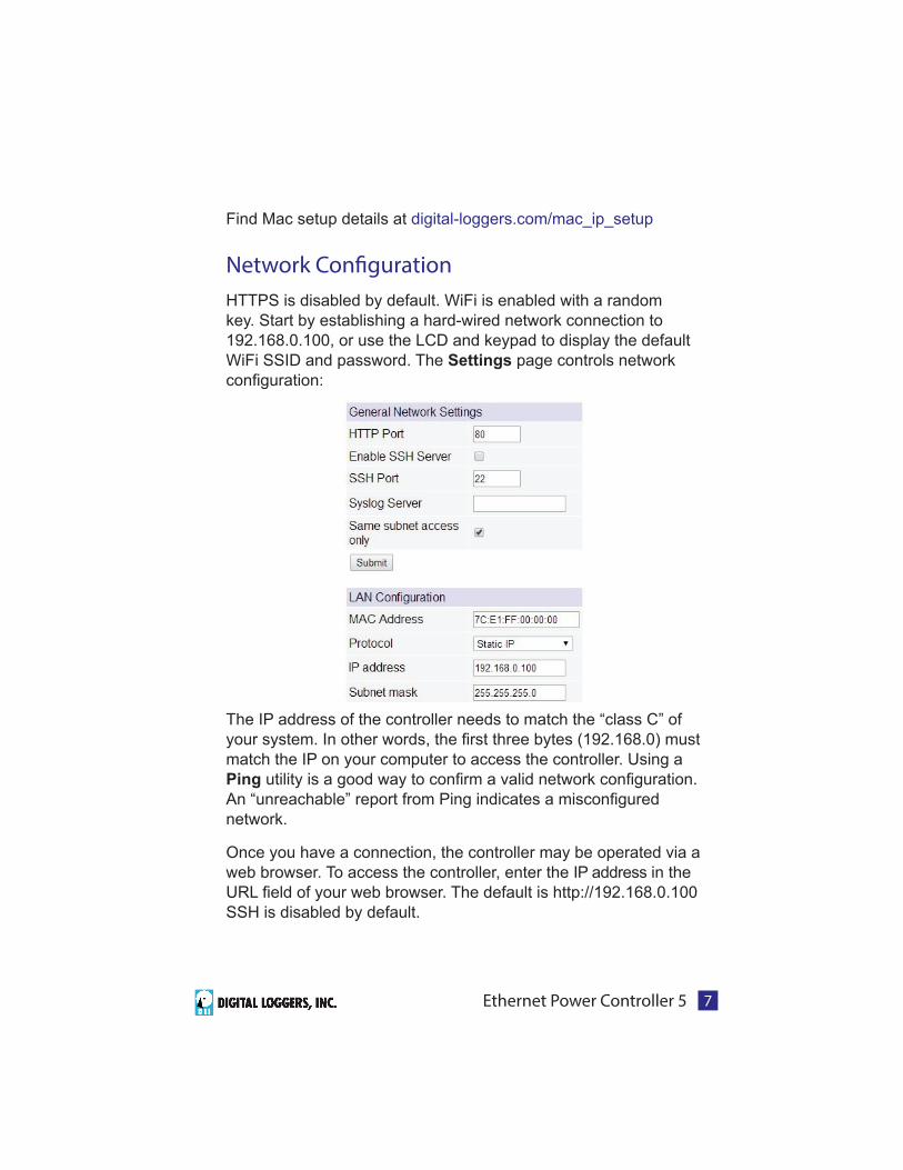
Max OS X
Turn AirPort off temporarily. Click the Apple logo, then System
Preferences, then Network. Select Built-In Ethernet and then
Confi gure. Under the TCP/IP tab, select Manually and enter an IP
address such as 192.168.0.0 as shown:
Make changes shown. Point a browser to 192.168.0.100 Log in.
Ethernet Power Controller 5 7
Find Mac setup details at digital-loggers.com/mac_ip_setup
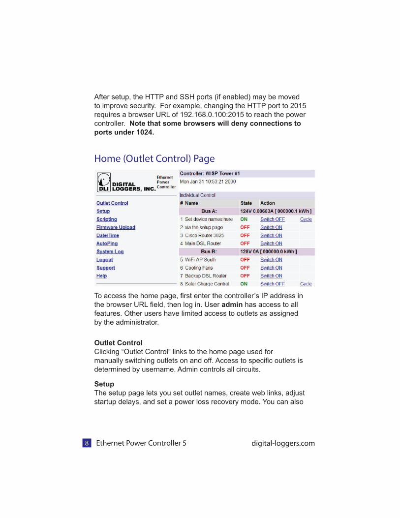
Network Con! guration
HTTPS is disabled by default. WiFi is enabled with a random
key. Start by establishing a hard-wired network connection to
192.168.0.100, or use the LCD and keypad to display the default
WiFi SSID and password. The Settings page controls network
confi guration:
The IP address of the controller needs to match the “class C” of
your system. In other words, the fi rst three bytes (192.168.0) must
match the IP on your computer to access the controller. Using a
Ping utility is a good way to confi rm a valid network confi guration.
An “unreachable” report from Ping indicates a misconfi gured
network.
Once you have a connection, the controller may be operated via a
web browser. To access the controller, enter the IP address in the
URL fi eld of your web browser. The default is http://192.168.0.100
SSH is disabled by default.
Ethernet Power Controller 5 digital-loggers.com8
After setup, the HTTP and SSH ports (if enabled) may be moved
to improve security. For example, changing the HTTP port to 2015
requires a browser URL of 192.168.0.100:2015 to reach the power
controller. Note that some browsers will deny connections to
ports under 1024.
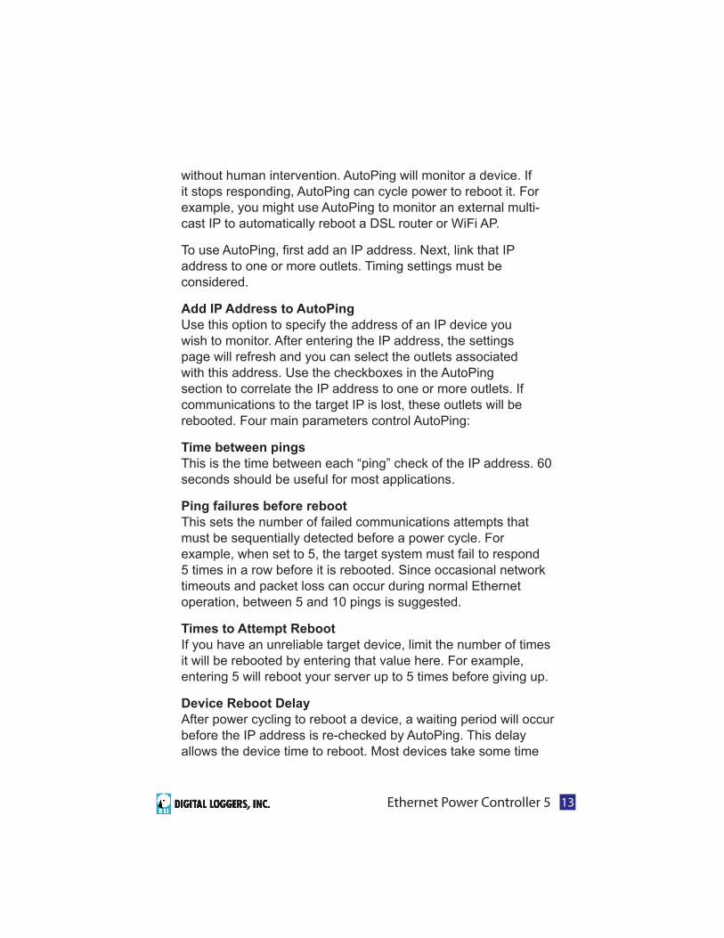
Home (Outlet Control) Page
To access the home page, fi rst enter the controller’s IP address in
the browser URL fi eld, then log in. User admin has access to all
features. Other users have limited access to outlets as assigned
by the administrator.
Outlet Control
Clicking “Outlet Control” links to the home page used for
manually switching outlets on and off. Access to specifi c outlets is
determined by username. Admin controls all circuits.
Setup
The setup page lets you set outlet names, create web links, adjust
startup delays, and set a power loss recovery mode. You can also

Ethernet Power Controller 5 9
add user accounts and change login credentials on this page.
Scripting
An updated scripting language based on Lua lets you customize
the power controller. Scripts may be started manually,
automatically on power-up, by external http commands, or by
AutoPing events. Find a list of commands and examples at:
digital-loggers.com/scripts.html
AutoPing
The AutoPing page lets you set parameters to automatically
reboot attached equipment. First, specify an IP address to ping.
Next, adjust the timing settings and use the checkboxes to link the
IP to power circuits. For example, if a router is unreachable, you
may choose to automatically reboot both a router and a switch
attached to two different circuits. Learn more: digital-loggers.com/
AutoPing
System Log
The power controller keeps an internal event log including logins,
outlet switching, power interruptions, and AutoPing events. Recent
events are stored in the log and accessible from the System Log
page. SYSLOG export is supported. For more information: digital-
loggers.com/syslog.html
Logout
Browser logout is automatic when a session is closed or after a
time-out period. Use this link to log-out in advance.
Programmable Web Links
User-defi ned web links are provided. Set names and destination
URLs for these links on the Settings page. These are convenient
for connecting to other power controllers or to remote sites.
Switching Outlets On and O" The outlet control page lets you control any duplex outlet (except
the always-on pair). A master control allows those users with
access to switch all outlets on or off.
To switch an outlet, simply click to the right of the outlet name or

Ethernet Power Controller 5 digital-loggers.com10
number. On->Off switching is immediate Off->On switching is
subject to the confi gurable On Sequence Delay..
Use the keypad for local control: Select an outlet using the
arrow keys, then press on, off, or cycle. Press ON or OFF for
5 seconds to lock or unlock an outlet. Locking prevents web
access. To change the display mode, press the up and down
arrows simultaneously. The keypad may be disabled on the
Setup page.
You may want to Cycle a device which is connected to the
controller. This feature is useful for rebooting Ethernet devices
which may interrupt the web link to the controller. Clicking Cycle
switches power off, waits for the Cycle time, and then switches
power back on while conforming to the ON Sequence Delay.
This reboots the attached device.
You can also cycle all outlets using the Master Control on the
bottom of the page. An adjustable ON sequence
delay takes effect when outlets are turned on
one after another, ehether when using the All
Outlets On button, on power-up, or when
switching manually using the front panel. This
prevents power surges. A separate Cycle delay
setting is provided on the setup page.
Depending on your web browser settings, you may need to click
the Refresh button or F5 key to update the on-screen status
display after changing settings. Screen refresh rate is adjusted
in two places: on the Setup page and in your browser settings.
Setup Page
The Setup page allows the admin to confi gure:

Ethernet Power Controller 5 11
Controller and Outlet Names
Use the controller name fi eld to assign a Controller Name to the
power controller itself. An example is Server Rack 4 PDU.. The
Controller Name will appear on top of all pages. Assign a separate
name to each outlet, such as DSL Router 1 or Email Server to aid
identifi cation. Check the Confi rm button to the right of the outlet
name if you would like a pop-up window to appear before switching
critical outlets.
Power-On Sequence Delay
When a time value is entered in the All ON Sequence Delay fi eld,
the power controller will pause for a period of time before switching
each outlet on in sequence. This delay helps prevent power
surges and blown circuit breakers which can occur when multiple
devices are switched on simultaneously. A delay of 60 seconds is
suggested for server applications.
You may also enter a screen refresh delay in this section. If Enable
screen refresh is checked, and a delay value is entered, your
browser should periodically update the status screen.
Wrong Password Lockout
After three failed login attempts, the switch can disable access for
a selected period of time (0-60 Minutes).
Power Loss Recovery Modes
The power loss recovery mode setting has a very important setting
that determines operation after a power failure:
1. Turn all outlets off (all systems will be switched off until
manually turned on later, possibly by a script).
2. You can automatically turn all outlets on using the

Ethernet Power Controller 5 digital-loggers.com12
sequence delay timer described above.
3. You can return to the same outlet settings that were
used prior to the power loss. ie. 1 On, 2 Off, etc. The ON
Sequency delay timer is used here as well.
Note: If you have written a power-on script, the recovery mode
takes effect before script execution begins. Scripts start after self-
test, approximately 30 seconds after power-up.
User Defi ned Links
Add hyperlinks to other power controllers, your own web pages,
or remote web sites by entering URLs in the Setup page. For
example, enter “Site Two Power Controller” in the description fi eld
and a URL of “192.168.0.250” These links appear on the left side
of the web pages.
Access Control
The administrator can grant users access to only certain
outlets. To set permissions, login as admin fi rst, then create
a permissions matrix by entering user names on the left and
checking allowed outlets on the right.
Network Settings
A valid fi xed IP address, network mask, and gateway must be
entered in this section.
When changing IPs, you may need to restart your network switch
to validate the new IP on an “auto-confi guring” switch port. Be
sure to record the new IP address.
Use the Protect button to lock the network settings. Once
protected, the network settings cannot be changed except by
pressing the physical reset button below the LCD.
AutoPing TM
AutoPing Operation and Settings
AutoPing is an automatic system for rebooting IP equipment
Ethernet Power Controller 5 13
without human intervention. AutoPing will monitor a device. If
it stops responding, AutoPing can cycle power to reboot it. For
example, you might use AutoPing to monitor an external multi-
cast IP to automatically reboot a DSL router or WiFi AP.
To use AutoPing, fi rst add an IP address. Next, link that IP
address to one or more outlets. Timing settings must be
considered.
Add IP Address to AutoPing
Use this option to specify the address of an IP device you
wish to monitor. After entering the IP address, the settings
page will refresh and you can select the outlets associated
with this address. Use the checkboxes in the AutoPing
section to correlate the IP address to one or more outlets. If
communications to the target IP is lost, these outlets will be
rebooted. Four main parameters control AutoPing:
Time between pings
This is the time between each “ping” check of the IP address. 60
seconds should be useful for most applications.
Ping failures before reboot
This sets the number of failed communications attempts that
must be sequentially detected before a power cycle. For
example, when set to 5, the target system must fail to respond
5 times in a row before it is rebooted. Since occasional network
timeouts and packet loss can occur during normal Ethernet
operation, between 5 and 10 pings is suggested.
Times to Attempt Reboot
If you have an unreliable target device, limit the number of times
it will be rebooted by entering that value here. For example,
entering 5 will reboot your server up to 5 times before giving up.
Device Reboot Delay
After power cycling to reboot a device, a waiting period will occur
before the IP address is re-checked by AutoPing. This delay
allows the device time to reboot. Most devices take some time

Ethernet Power Controller 5 digital-loggers.com14
to reboot. Windows and Linux servers can force automatic fi le
system checks which may take several minutes to complete. To
allow for startup delays, enter a time delay in the Device Reboot
Delay period. For example, a reasonable value for a typical server
might be 10 minutes (600 seconds). Entering 600 would cause
the power controller to start checking the server for normal IP
operation 10 minutes after reboot.
Find more details at: digital-loggers.com/AutoPing2.html
AutoPing Example
In this example, we use AutoPing to automatically reboot a DSL
router. Since the switch is connected inside the router, we select a
target IP of 8.8.8.8 This is a multi-cast address which connects to
a multitude of Google name servers. We can safely assume that if
none of them respond, we have lost network connectivity.
We connect the router to outlet 1, enter the external IP on the left,
and leave all timing values at defaults.
Internet AccessLike to access your power controller over the Internet? Learn

Ethernet Power Controller 5 15
how to confi gure your router at port-forward.com A fi rewall is
recommended.
Mobile Device Access Non-admin accounts have simplifi ed UI well suited for mobile
devices with small screens. Third-party applications are
available to control various DLI products from Android and IOS.
These apps are sold and supported by independent developers,
not by DLI. Learn more: digital-loggers.com/mobile.html
Real-Time Clock
An internal Real-Time-Clock (RTC) is provided. This clock can
be set manually using the Date/Time link. The time zone can be
selected based on GMT. Internal batteries have an estimated
15-year lifetime.
Web Server Backup Power
A rechargable battery pack maintains web server operation
for a few minutes during power failures. Open the battery
compartment door by depressing the latch to the left of the door
to access the battery and connect the cable. Allow 48 hours for
full recharge.
Lua Scripting
The controller can be customized using the Lua language. A full
description is beyond the scope of this manual, so please visit
lua.org and review the examples at:
digital-loggers.com/scripts.html

Ethernet Power Controller 5 digital-loggers.com
Power Metering
Four web meters provide voltage and current readings on the
A&B bus. Cumulative killowatt hours are displayed. For non-
PFC corrected loads, a power factor correction value may be
manually enetered on the setup page. Current metering includes
only the switched outlets. Co-location users may elect to use the
unswitched outlets for “house power”. To avoid tripped breakers,
take the current drain of the unmetered outlets into account when
operating near the 15A maximum rating.
Meters & ChartsHistograms can be created with user-selectable time scales and
metering sources. The AC input current on each bus, AC input
voltage, battery voltage, and CPU / Relay voltages are metered.
A thermistor monitors CPU and control board temperature, which
should not exceed 185F. The 5V meter monitors the control board
VCC, and the 12V meter indicates control relay power. Batteries
are fully charged at 5.60V and 90% discharged at 4.60V.
Safety ShutdownOver-current, over-voltage, and low-voltage shutdown are
provided on the safety shudown page. Take care when using this
feature so as not to create an oscillating condition.
Open Source CodeIn compliance with the spirit of the GNU public license, source
code is provided for reference. Purchasing a TLA and signing an
NDA from Atheros are highly recommended before attempting
any custom development. DLI cannot provide warranty or tech
support for modifi ed units.
Technical Support Please register. Painless on-line registration gets you free tech

Ethernet Power Controller 5 1714
Speci! cations
Alert Beeper 73dBa at 12”. Programmable.
Applications Commercial, industrial, and residential remote power control and reboot. Indoor use only.
Circuit Breakers Manual reset, 15A Thermal, UL Supplemental
Clock / RTC 15 year Li battery
Controls / Display Reset -to-factory-default switch, 2x16 Backlit LCD w/ PowerSave, 5 button keypad, E-Stop
Enclosure Steel, double grounded. Vented 4 sides. Fanless.
Ethernet Interface 10/100 autosensing, Static IP, TCP port selectable, 8 pin RJ-45 w/ internal FCC ! ltering
FCC Testing Part 15 FCC ID 2ACIUEPCR5
Humidity 8-80% RH Operating
Input Power Cord Fixed 14AWG with 5-15 plug standard
Inlet and Outlet Rating UL, CSA 15A, 120VAC only
Input Frequency Power supply - DC-400Hz
Metering Accuracy +/- 2V, +/- .5A when calibrated 50-60Hz only.
Operating Temperature -30º to 170ºF, -34º to 77ºC
Options - Factory Input cord length and 120V plug style
Power Supply Rating 90-240V, AC/DC Autosensing
Password Transmission Encrypted, base 64 or HTTPS
Power Dissipation 4.9W Typ Max (all on) <3 W idle
Power Fail Hold-Over 350ms minimum (all relays on)
Power-Up Modes Last used settings, all power on or o" , sequential on or run user-script ~30s after power-up
Relay Contact Spec 15-25A AC/DC, 1/2HP
Surge Protection Dual 3600WMetal Oxide Varistors
Size 3.5x5.5x19” 8.9x14x48cm 2-U
Weight (packed) Single unit 10.3lbs 4.7kg
WiFi Atheros 9331 2.4G 802.11n RP-SMA - FCC Note: The EPCR5 may only be used with (1) the manu facturer supplied antenna (Gain: 2.0dBi),or (2) a 50 Ohm antenna of equal or lesser gain.

Ethernet Power Controller 5 digital-loggers.com18
Limited Five Year Warranty
The terms of this warranty may be legally binding. If you do not agree to the terms listed below, return the product immediately in original unopened condition for a full refund. The purchaser assumes the entire risk as to the results and performance of the unit. DLI warrants this power controller to be free from major defects. No agency, country, or local certifi cations are included with this unit. It is the responsibility of the user to obtain such certifi cations if necessary for the customer’s application. Buyer acknowledges and agrees that he is solely responsible for proper use, certifi cation and safety testing of components supplied by DLI. DLI’s entire liability and exclusive remedy as to defective hardware shall be, at DLI’s option, either (a) return of the purchase price or (b) replacement or repair of the hardware that does not meet DLI’s quality control standards and has been returned through proper RMA procedures. DLI’s liability for repair or replacement is to DLI’s customer ONLY. NO SUPPORT IS PROVIDED FOR MODIFIED FIRMWARE. MODIFICATION OF FIRMWARE VOIDS ALL WARRANTY. Warranty service requires an original invoice from DLI and an RMA number provided by technical support. RMA material must be shipped prepaid to DLI. RMA numbers are valid for 15 days from date of issue. This warranty does not cover products which are modifi ed (including fi rmware modifi cations), subjected to rough handling, or used in applications for which they were not originally intended. Batteries are not covered under warranty. Physical damage caused by customer or in transit to DLI is not covered under warranty. Please insure your shipments. No oral advice or verbal warranties made by DLI’s employees, dealers, or distributors shall in any way increase the scope of this warranty. DLI makes no warranty as to merchantability or fi tness for any particular purpose. DLI assumes no liability for incidental or consequential damages arising from the use or inability to use this product. This warranty gives you specifi c legal rights. You may also have other rights that vary from state to state. Since some states do not allow the exclusion of liability for consequential damages, some of the above limitations may not apply to you. Auto-PingTM is a registered trademark of Computer Performance, Inc. Since this is a FLASH based product, fi rmware should not be updated over the Internet or a busy LAN. Packet loss could result in FLASH corruption, requiring mail-in service. This product is designed for indoor use only. It is not intended for and should not be used in outdoor, mobile, airborne, or FDA Class III applications.
DIGITAL LOGGERS, INC. 2695 Walsh Avenue
Santa Clara, CA 95051
Digital-Loggers.com
© 2015 DLI This product is protected by pending US patents and foreign patents
Released 11/10/2015

Ethernet Power Controller 5 19
Web Enabled DIN Relay
Related Products:
Call (408) 330-5599
2x50A, 8x15A DC Smart Switch (+12,+24, or -48)
Smart PoE Injector
90-240VAC Smart PDU

2695 Walsh Ave, Santa Clara, CA 95051
(408) 330-5599 digital-loggers.com