Embed Size (px)
Citation preview
User’s Guide
ICON Touch 4.3 CTS Display

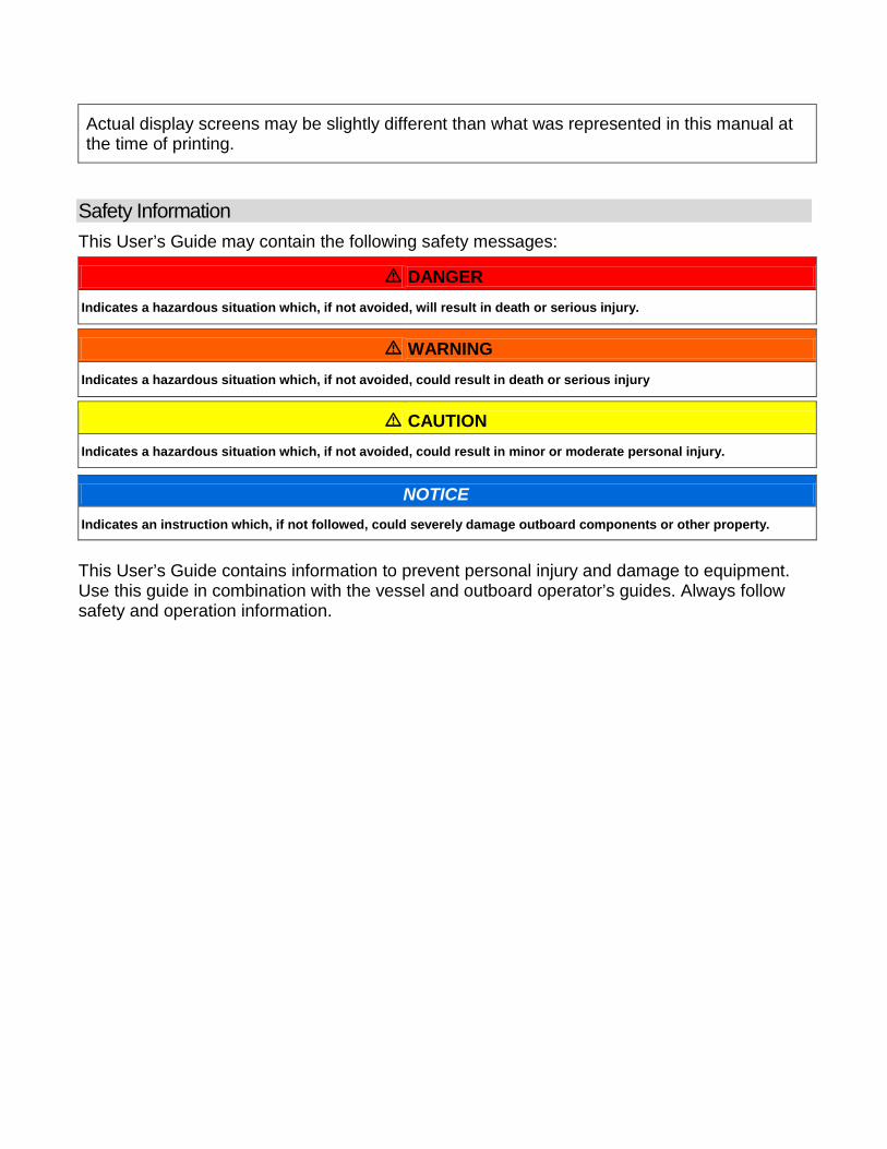
Actual display screens may be slightly different than what was represented in this manual at the time of printing.
Safety Information This User’s Guide may contain the following safety messages:
DANGER Indicates a hazardous situation which, if not avoided, will result in death or serious injury.
WARNING Indicates a hazardous situation which, if not avoided, could result in death or serious injury
CAUTION Indicates a hazardous situation which, if not avoided, could result in minor or moderate personal injury.
NOTICE Indicates an instruction which, if not followed, could severely damage outboard components or other property.
This User’s Guide contains information to prevent personal injury and damage to equipment. Use this guide in combination with the vessel and outboard operator’s guides. Always follow safety and operation information.
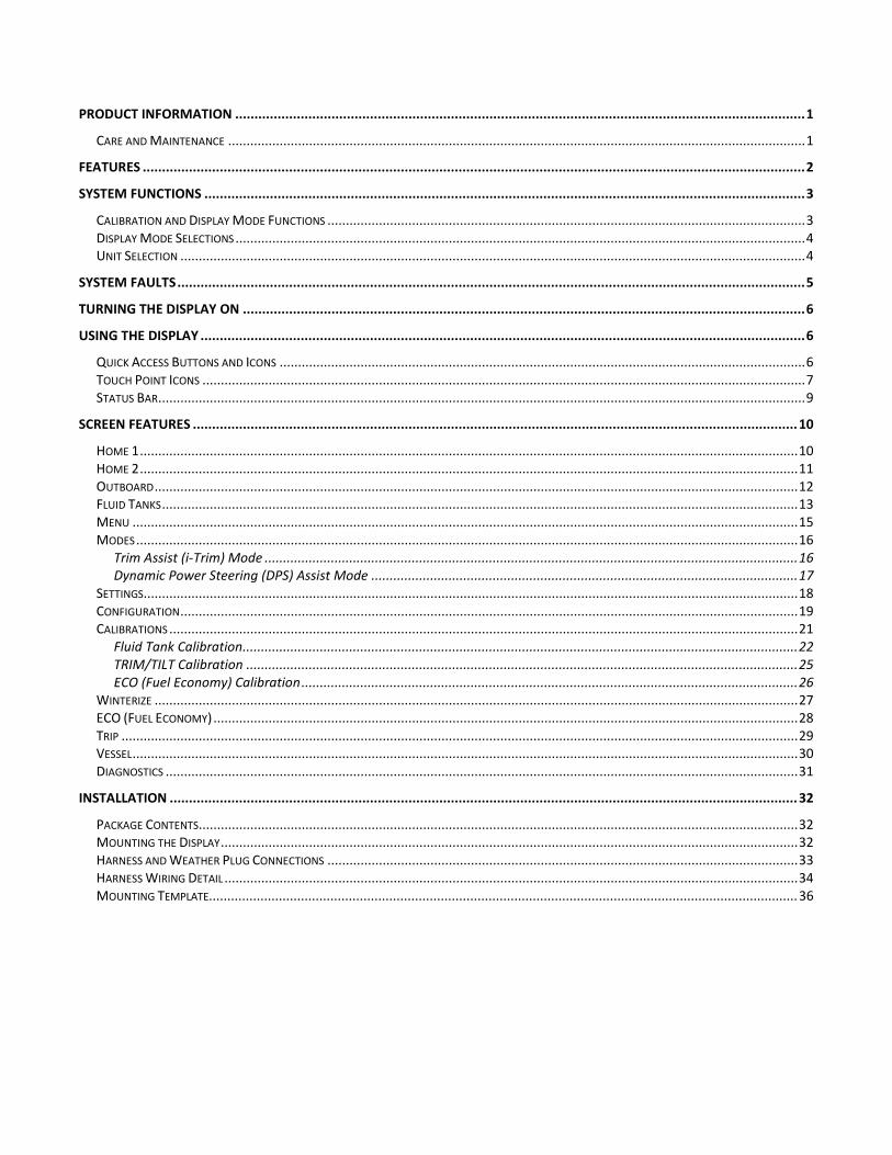
PRODUCT INFORMATION .................................................................................................................................................... 1
CARE AND MAINTENANCE ............................................................................................................................................................. 1
FEATURES ............................................................................................................................................................................ 2
SYSTEM FUNCTIONS ............................................................................................................................................................ 3
CALIBRATION AND DISPLAY MODE FUNCTIONS .................................................................................................................................. 3 DISPLAY MODE SELECTIONS ........................................................................................................................................................... 4 UNIT SELECTION .......................................................................................................................................................................... 4
SYSTEM FAULTS ................................................................................................................................................................... 5
TURNING THE DISPLAY ON .................................................................................................................................................. 6
USING THE DISPLAY ............................................................................................................................................................. 6
QUICK ACCESS BUTTONS AND ICONS ............................................................................................................................................... 6 TOUCH POINT ICONS .................................................................................................................................................................... 7 STATUS BAR ................................................................................................................................................................................ 9
SCREEN FEATURES ............................................................................................................................................................. 10
HOME 1 ................................................................................................................................................................................... 10 HOME 2 ................................................................................................................................................................................... 11 OUTBOARD ............................................................................................................................................................................... 12 FLUID TANKS ............................................................................................................................................................................. 13 MENU ..................................................................................................................................................................................... 15 MODES .................................................................................................................................................................................... 16
Trim Assist (i-Trim) Mode ................................................................................................................................................. 16 Dynamic Power Steering (DPS) Assist Mode .................................................................................................................... 17
SETTINGS .................................................................................................................................................................................. 18 CONFIGURATION ........................................................................................................................................................................ 19 CALIBRATIONS ........................................................................................................................................................................... 21
Fluid Tank Calibration....................................................................................................................................................... 22 TRIM/TILT Calibration ...................................................................................................................................................... 25 ECO (Fuel Economy) Calibration ....................................................................................................................................... 26
WINTERIZE ............................................................................................................................................................................... 27 ECO (FUEL ECONOMY) ............................................................................................................................................................... 28 TRIP ........................................................................................................................................................................................ 29 VESSEL ..................................................................................................................................................................................... 30 DIAGNOSTICS ............................................................................................................................................................................ 31
INSTALLATION ................................................................................................................................................................... 32
PACKAGE CONTENTS ................................................................................................................................................................... 32 MOUNTING THE DISPLAY ............................................................................................................................................................. 32 HARNESS AND WEATHER PLUG CONNECTIONS ................................................................................................................................ 33 HARNESS WIRING DETAIL ............................................................................................................................................................ 34 MOUNTING TEMPLATE................................................................................................................................................................ 36

Product Information The Evinrude® ICON TOUCH 4.3 CTS Display is designed for use with Evinrude E-TEC® G2 V6 outboards. The display communicates with the outboard and remote control, as well as other network connected devices, by means of a NMEA 2000® compliant network. The display handles standard NMEA 2000 messages and proprietary messages. The display controls a number of helm functions and options. Some options and modes of operation are not possible to access without this display present in the system. Select outboard sensor calibrations and functions are also accessible through the display. The display incorporates a 4.3 in. (109 mm) color screen with touch screen technology.
Care and Maintenance Use a soft cloth to clean the display. Window cleaner or alcohol can be used to clean the screen. Do not use harsh or abrasive cleaners on the display.
356595-01
1
Features • "High Resolution" 4.3 in. (109 mm) - 800 x 480 WVGA color display
• Bonded display enhances sunlight visibility o Viewable with polarized sunglasses (45 degree polarization) o Bright illumination - 450 Nit (450 cd/m2)
• Touch screen projected capacitive technology o Not usable with gloved hands
• Firmware update capability via USB interface
• Integrates with Evinrude ICON II remote controls and Evinrude E-TEC G2 V6 outboards
• NMEA 2000 network interface
• Preconfigured and user selectable screens
• Descriptive text for fault codes and procedures
• Multi-language support
2

System Functions The display provides a number of user selectable modes and configuration menus. Select modes affect display unit selection and screen appearance. Other modes interact with and affect remote control and outboard operation and functionality. The display interacts with other system components including the outboard(s) and the remote control(s). The modes are used to select specific outboard or remote control operational characteristics, system wide diagnostic functions, and sensor calibration functions.
Calibration and Display Mode Functions • Calibration for:
o Tilt maximum level
o Trim upper and lower limits
o Fluid tank volumes and levels – up to 10 total
• Mode function for:
o Winterization
o Dynamic Power Steering (DPS) control
o iTrim control
• Hand or Foot Throttle selection
• Transom position of the outboard
• Backlight control
3
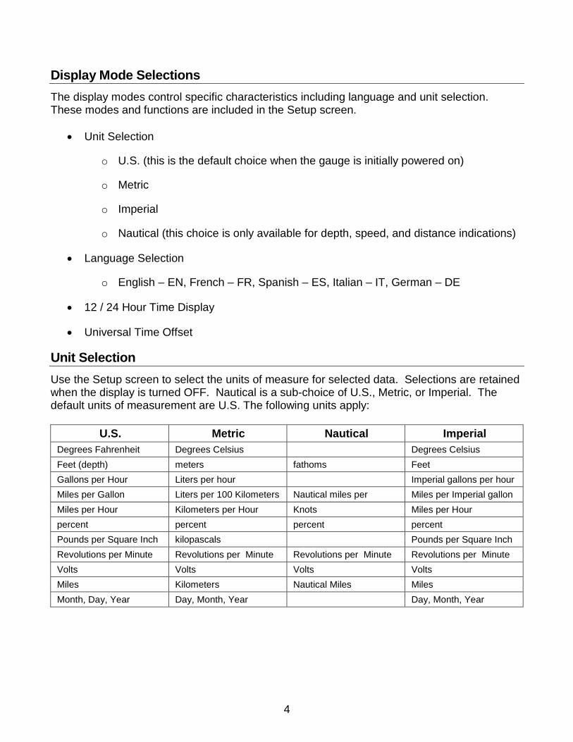
Display Mode Selections The display modes control specific characteristics including language and unit selection. These modes and functions are included in the Setup screen.
• Unit Selection
o U.S. (this is the default choice when the gauge is initially powered on)
o Metric
o Imperial
o Nautical (this choice is only available for depth, speed, and distance indications)
• Language Selection
o English – EN, French – FR, Spanish – ES, Italian – IT, German – DE
• 12 / 24 Hour Time Display
• Universal Time Offset
Unit Selection Use the Setup screen to select the units of measure for selected data. Selections are retained when the display is turned OFF. Nautical is a sub-choice of U.S., Metric, or Imperial. The default units of measurement are U.S. The following units apply:
U.S. Metric Nautical Imperial Degrees Fahrenheit Degrees Celsius Degrees Celsius Feet (depth) meters fathoms Feet Gallons per Hour Liters per hour Imperial gallons per hour Miles per Gallon Liters per 100 Kilometers Nautical miles per Miles per Imperial gallon Miles per Hour Kilometers per Hour Knots Miles per Hour percent percent percent percent Pounds per Square Inch kilopascals Pounds per Square Inch Revolutions per Minute Revolutions per Minute Revolutions per Minute Revolutions per Minute Volts Volts Volts Volts Miles Kilometers Nautical Miles Miles Month, Day, Year Day, Month, Year Day, Month, Year
4
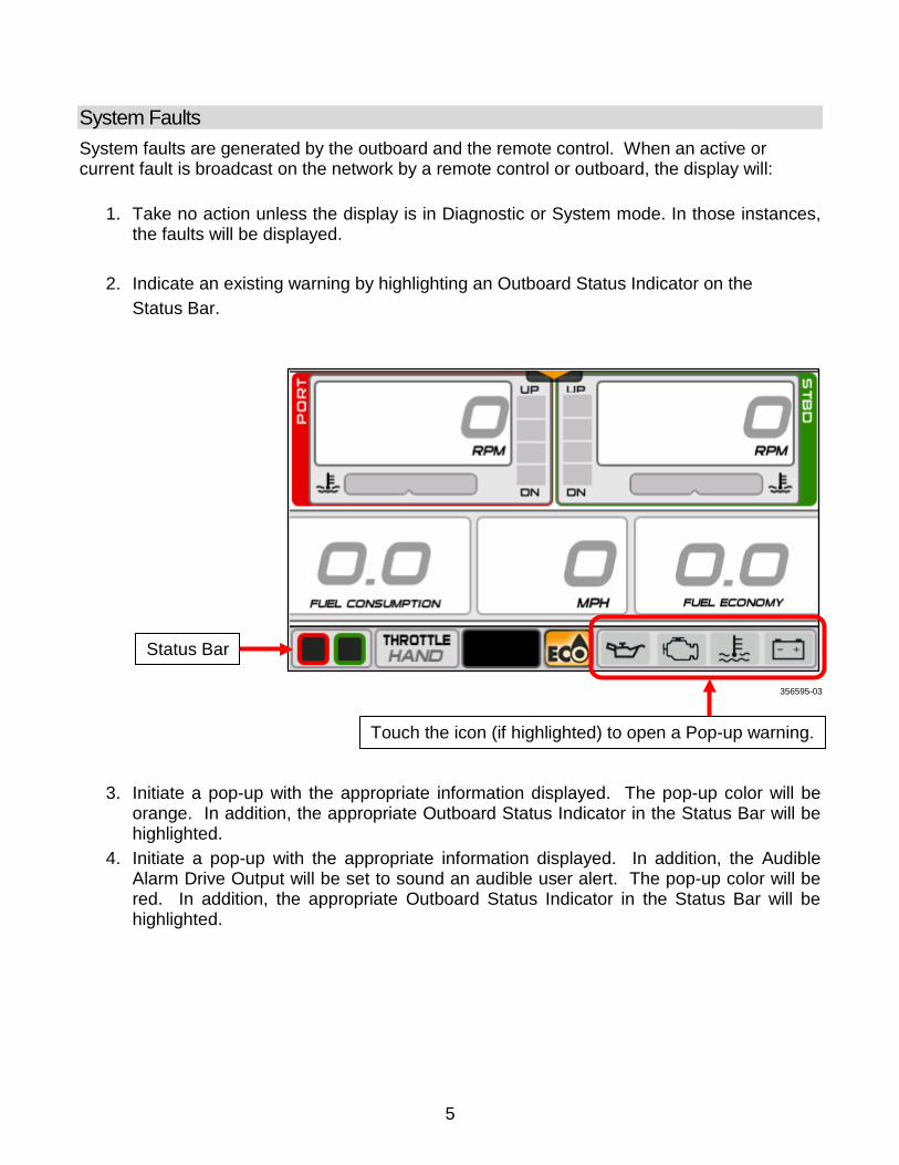
System Faults System faults are generated by the outboard and the remote control. When an active or current fault is broadcast on the network by a remote control or outboard, the display will:
1. Take no action unless the display is in Diagnostic or System mode. In those instances, the faults will be displayed.
2. Indicate an existing warning by highlighting an Outboard Status Indicator on the Status Bar.
3. Initiate a pop-up with the appropriate information displayed. The pop-up color will be orange. In addition, the appropriate Outboard Status Indicator in the Status Bar will be highlighted.
4. Initiate a pop-up with the appropriate information displayed. In addition, the Audible Alarm Drive Output will be set to sound an audible user alert. The pop-up color will be red. In addition, the appropriate Outboard Status Indicator in the Status Bar will be highlighted.
356595-03
Status Bar
Touch the icon (if highlighted) to open a Pop-up warning.
5
A pop-up and audible warning will remain in effect until acknowledged by the operator by touching the pop-up area. As long as the fault is active, the pop-up may be re-initiated by touching the right-hand side of the Outboard Status Indicator area of the Status Bar.
Turning the Display ON Turn the key switch to the ON position or start the outboard to turn the display ON.
Troubleshooting Tip
Problem Solution
Display does not power ON.
Charge the network power supply battery to a minimum of 12.5V. Disconnect wiring harness from back of gauge, and then securely reconnect it.
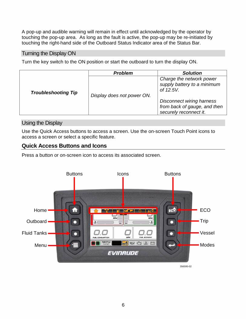
Using the Display Use the Quick Access buttons to access a screen. Use the on-screen Touch Point icons to access a screen or select a specific feature.
Quick Access Buttons and Icons Press a button or on-screen icon to access its associated screen.
Buttons Buttons Icons
356595-02
Home
Outboard
Fluid Tanks
Menu
ECO
Trip
Vessel
Modes
6

Touch Point Icons The touch point icons are located at the top of the screens. Touch the icons to navigate to the selected screen.
Touch point icons are also located on the Menu screen.
356595-04
Home Outboard Fluid Tanks Vessel Trip ECO
12:00
356595-05
Home
Outboard
Fluid Tanks
Settings
ECO
Trip
Vessel
Modes
7
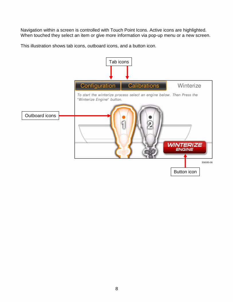
Navigation within a screen is controlled with Touch Point Icons. Active icons are highlighted. When touched they select an item or give more information via pop-up menu or a new screen. This illustration shows tab icons, outboard icons, and a button icon.
Tab icons
Outboard icons
Button icon
356595-06
8
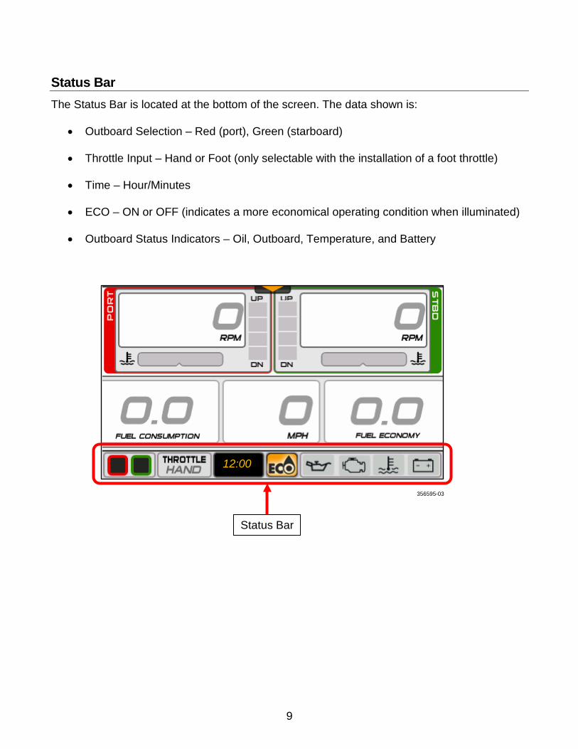
Status Bar The Status Bar is located at the bottom of the screen. The data shown is:
• Outboard Selection – Red (port), Green (starboard)
• Throttle Input – Hand or Foot (only selectable with the installation of a foot throttle)
• Time – Hour/Minutes
• ECO – ON or OFF (indicates a more economical operating condition when illuminated)
• Outboard Status Indicators – Oil, Outboard, Temperature, and Battery
356595-03
12:00
Status Bar
9
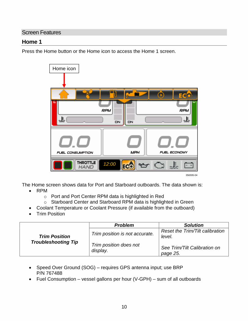
Screen Features Home 1 Press the Home button or the Home icon to access the Home 1 screen.
The Home screen shows data for Port and Starboard outboards. The data shown is:
• RPM o Port and Port Center RPM data is highlighted in Red o Starboard Center and Starboard RPM data is highlighted in Green
• Coolant Temperature or Coolant Pressure (if available from the outboard) • Trim Position
Trim Position Troubleshooting Tip
Problem Solution
Trim position is not accurate. Trim position does not display.
Reset the Trim/Tilt calibration level. See Trim/Tilt Calibration on page 25.
• Speed Over Ground (SOG) – requires GPS antenna input; use BRP P/N 767488
• Fuel Consumption – vessel gallons per hour (V-GPH) – sum of all outboards
356595-04
Home icon
12:00
10
• Fuel Economy – miles per gallon (MPG) – requires Speed Over Ground input (from GPS antenna) or Speed Over Water (SOW) input
o Speed Over Water input requires the use of one of the following transducers: BRP P/N 764671 – Transom mount (speed, depth, temp) transducer BRP P/N 764673 – Thru hull (speed, depth, temp) transducer BRP P/N 765150 – Transom mount (speed only) transducer
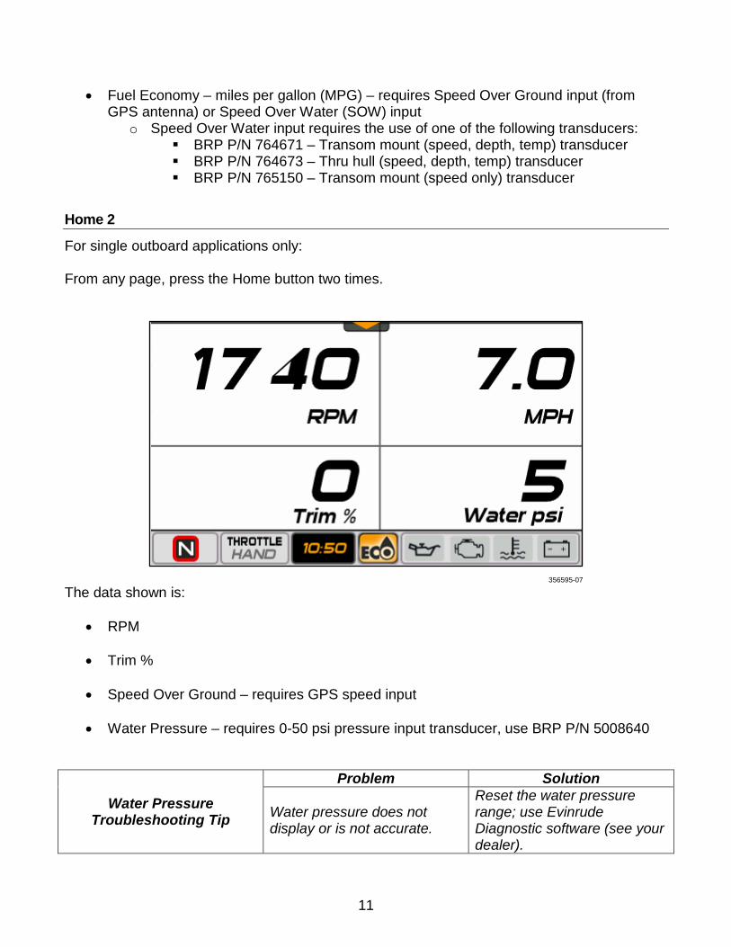
Home 2
For single outboard applications only: From any page, press the Home button two times.
The data shown is:
• RPM
• Trim %
• Speed Over Ground – requires GPS speed input
• Water Pressure – requires 0-50 psi pressure input transducer, use BRP P/N 5008640
Water Pressure Troubleshooting Tip
Problem Solution
Water pressure does not display or is not accurate.
Reset the water pressure range; use Evinrude Diagnostic software (see your dealer).
356595-07
11
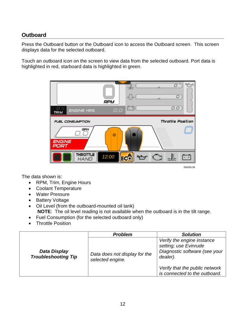
Outboard Press the Outboard button or the Outboard icon to access the Outboard screen. This screen displays data for the selected outboard. Touch an outboard icon on the screen to view data from the selected outboard. Port data is highlighted in red, starboard data is highlighted in green.
The data shown is:
• RPM, Trim, Engine Hours • Coolant Temperature • Water Pressure • Battery Voltage • Oil Level (from the outboard-mounted oil tank)
NOTE: The oil level reading is not available when the outboard is in the tilt range. • Fuel Consumption (for the selected outboard only) • Throttle Position
Data Display Troubleshooting Tip
Problem Solution
Data does not display for the selected engine.
Verify the engine instance setting; use Evinrude Diagnostic software (see your dealer). Verify that the public network is connected to the outboard.
356595-08
12:00
12
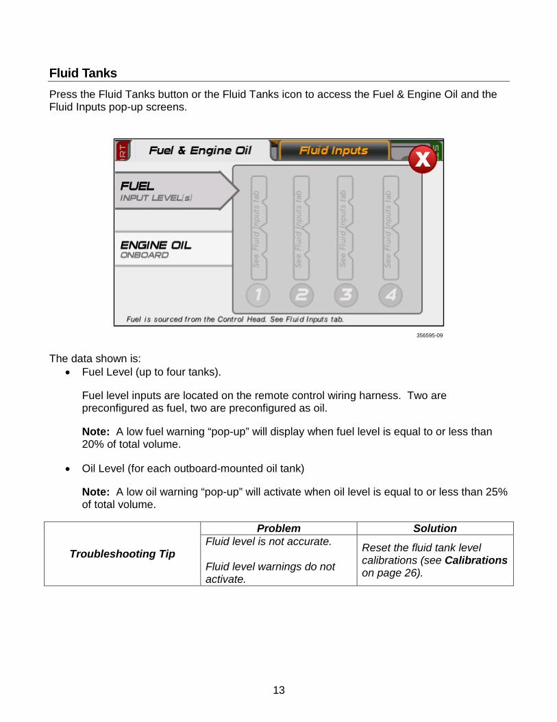
Fluid Tanks Press the Fluid Tanks button or the Fluid Tanks icon to access the Fuel & Engine Oil and the Fluid Inputs pop-up screens.
The data shown is:
• Fuel Level (up to four tanks).
Fuel level inputs are located on the remote control wiring harness. Two are preconfigured as fuel, two are preconfigured as oil.
Note: A low fuel warning “pop-up” will display when fuel level is equal to or less than 20% of total volume.
• Oil Level (for each outboard-mounted oil tank)
Note: A low oil warning “pop-up” will activate when oil level is equal to or less than 25% of total volume.
Troubleshooting Tip
Problem Solution Fluid level is not accurate. Fluid level warnings do not activate.
Reset the fluid tank level calibrations (see Calibrations on page 26).
356595-09
13
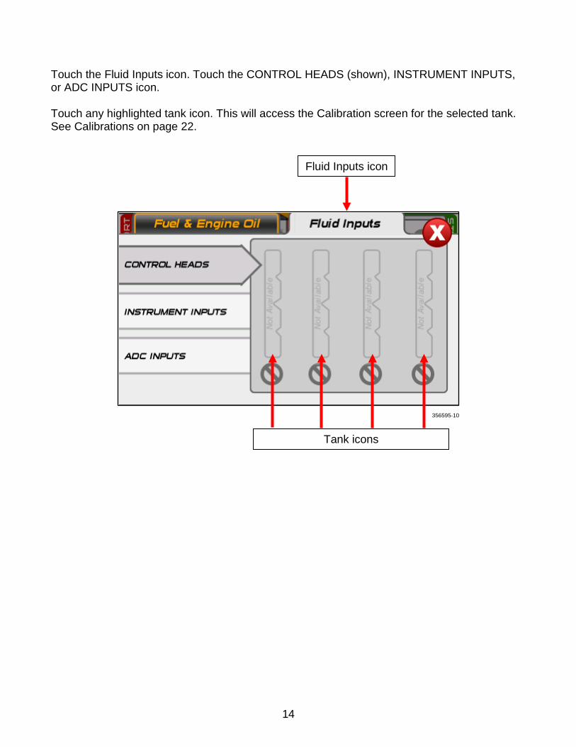
Touch the Fluid Inputs icon. Touch the CONTROL HEADS (shown), INSTRUMENT INPUTS, or ADC INPUTS icon. Touch any highlighted tank icon. This will access the Calibration screen for the selected tank. See Calibrations on page 22.
Fluid Inputs icon
Tank icons
356595-10
14
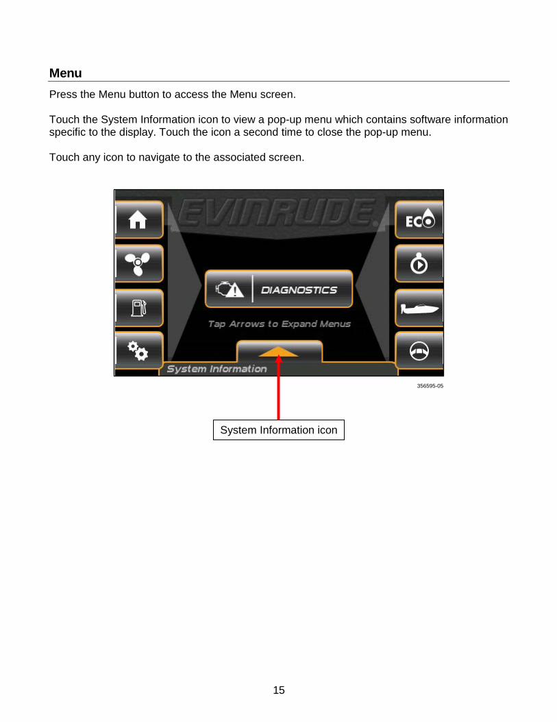
Menu Press the Menu button to access the Menu screen. Touch the System Information icon to view a pop-up menu which contains software information specific to the display. Touch the icon a second time to close the pop-up menu. Touch any icon to navigate to the associated screen.
356595-05
System Information icon
15
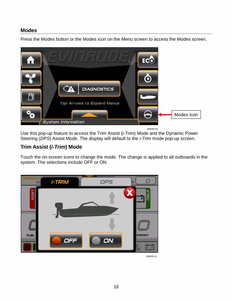
Modes Press the Modes button or the Modes icon on the Menu screen to access the Modes screen.
Use this pop-up feature to access the Trim Assist (i-Trim) Mode and the Dynamic Power Steering (DPS) Assist Mode. The display will default to the i-Trim mode pop-up screen.
Trim Assist (i-Trim) Mode
Touch the on-screen icons to change the mode. The change is applied to all outboards in the system. The selections include OFF or ON.
Modes icon
356595-05
356595-11
16
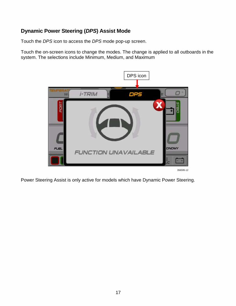
Dynamic Power Steering (DPS) Assist Mode
Touch the DPS icon to access the DPS mode pop-up screen. Touch the on-screen icons to change the modes. The change is applied to all outboards in the system. The selections include Minimum, Medium, and Maximum
Power Steering Assist is only active for models which have Dynamic Power Steering.
DPS icon
356595-12
17

Settings From the Menu screen, touch the Settings icon to access the Configuration, Calibrations, and Winterize screens. The display will default to the Configuration pop-up screen.
356595-05
Settings icon
18
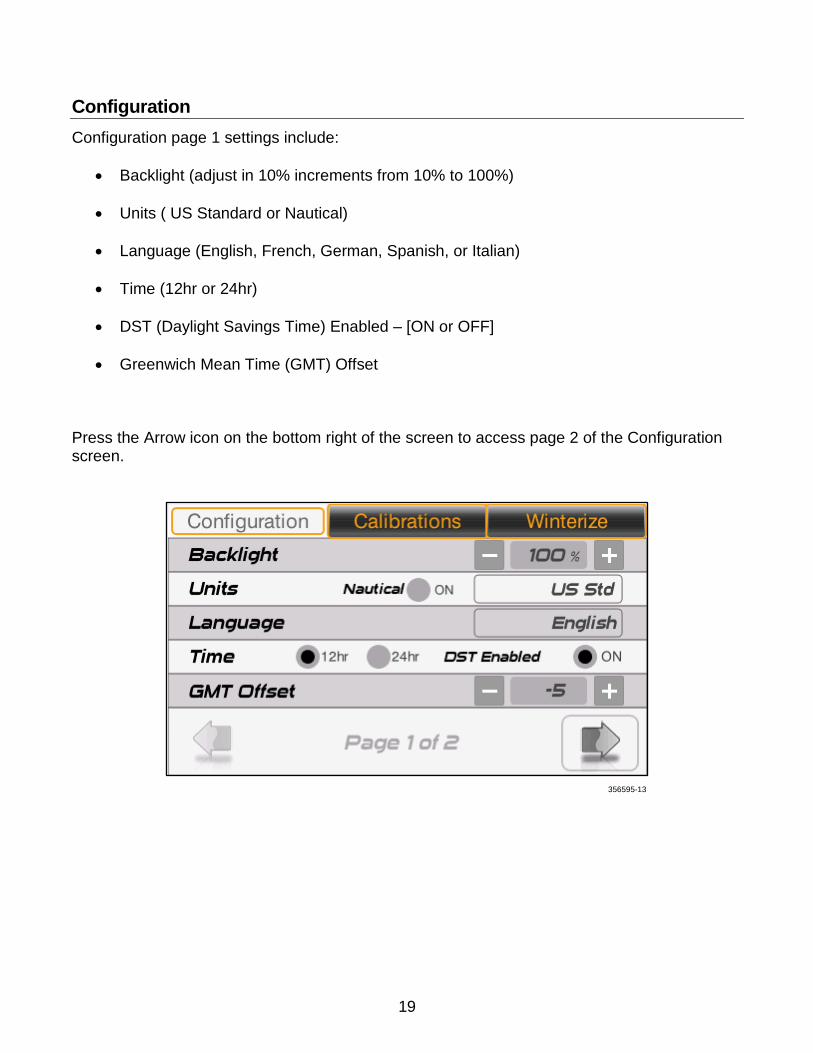
Configuration Configuration page 1 settings include:
• Backlight (adjust in 10% increments from 10% to 100%)
• Units ( US Standard or Nautical)
• Language (English, French, German, Spanish, or Italian)
• Time (12hr or 24hr)
• DST (Daylight Savings Time) Enabled – [ON or OFF]
• Greenwich Mean Time (GMT) Offset
Press the Arrow icon on the bottom right of the screen to access page 2 of the Configuration screen.
356595-13
19
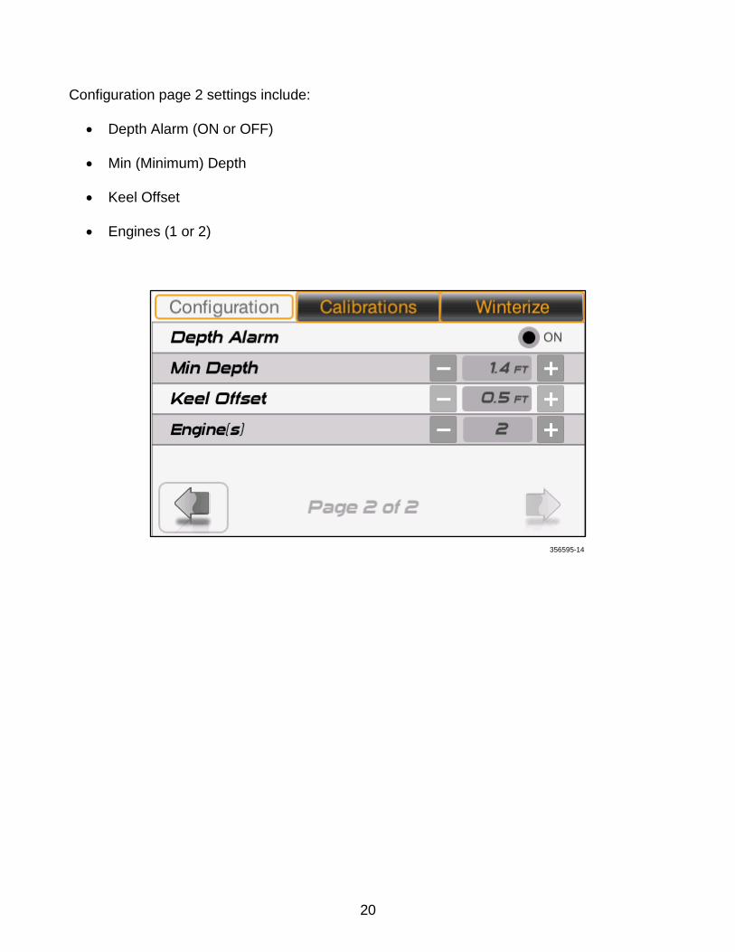
Configuration page 2 settings include:
• Depth Alarm (ON or OFF)
• Min (Minimum) Depth
• Keel Offset
• Engines (1 or 2)
356595-14
20
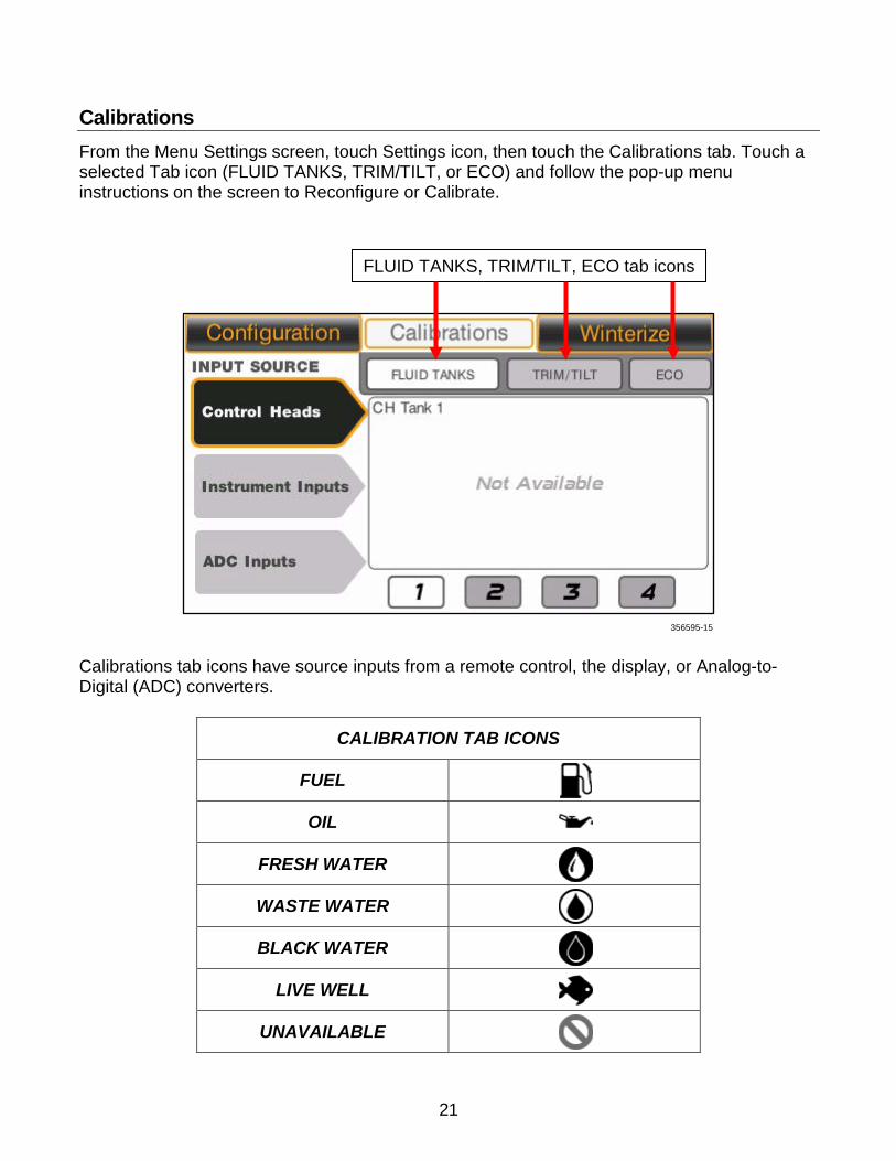
Calibrations From the Menu Settings screen, touch Settings icon, then touch the Calibrations tab. Touch a selected Tab icon (FLUID TANKS, TRIM/TILT, or ECO) and follow the pop-up menu instructions on the screen to Reconfigure or Calibrate.
Calibrations tab icons have source inputs from a remote control, the display, or Analog-to-Digital (ADC) converters.
CALIBRATION TAB ICONS
FUEL OIL
FRESH WATER WASTE WATER BLACK WATER
LIVE WELL UNAVAILABLE
FLUID TANKS, TRIM/TILT, ECO tab icons
356595-15
21
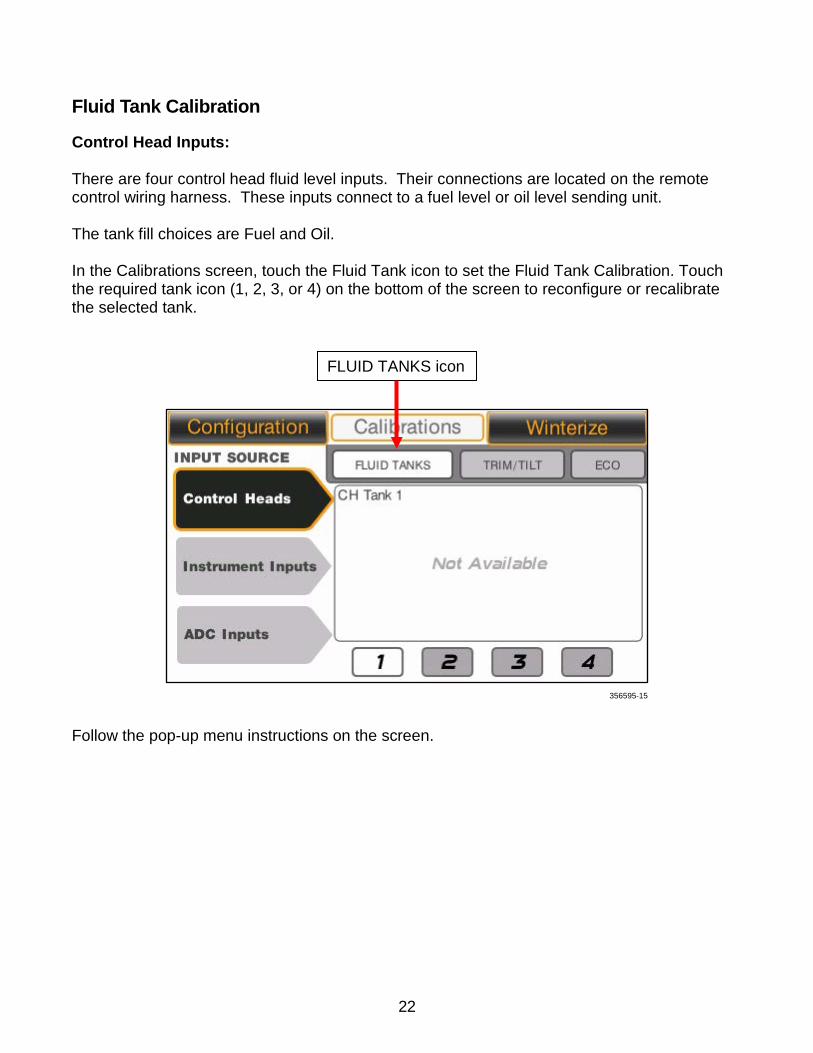
Fluid Tank Calibration
Control Head Inputs: There are four control head fluid level inputs. Their connections are located on the remote control wiring harness. These inputs connect to a fuel level or oil level sending unit. The tank fill choices are Fuel and Oil. In the Calibrations screen, touch the Fluid Tank icon to set the Fluid Tank Calibration. Touch the required tank icon (1, 2, 3, or 4) on the bottom of the screen to reconfigure or recalibrate the selected tank.
Follow the pop-up menu instructions on the screen.
FLUID TANKS icon
356595-15
22
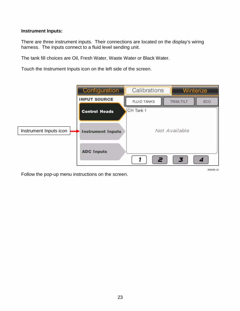
Instrument Inputs: There are three instrument inputs. Their connections are located on the display’s wiring harness. The inputs connect to a fluid level sending unit. The tank fill choices are Oil, Fresh Water, Waste Water or Black Water. Touch the Instrument Inputs icon on the left side of the screen.
Follow the pop-up menu instructions on the screen.
Instrument Inputs icon
356595-15
23
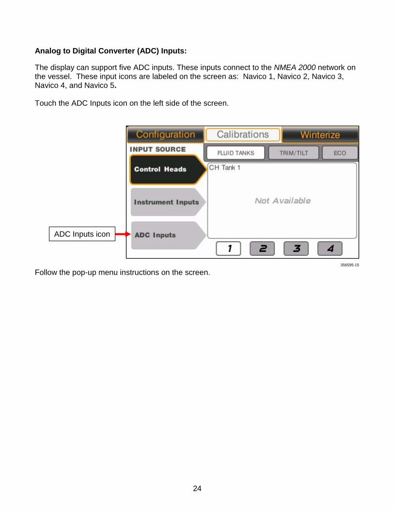
Analog to Digital Converter (ADC) Inputs:
The display can support five ADC inputs. These inputs connect to the NMEA 2000 network on the vessel. These input icons are labeled on the screen as: Navico 1, Navico 2, Navico 3, Navico 4, and Navico 5. Touch the ADC Inputs icon on the left side of the screen.
Follow the pop-up menu instructions on the screen.
ADC Inputs icon
356595-15
24
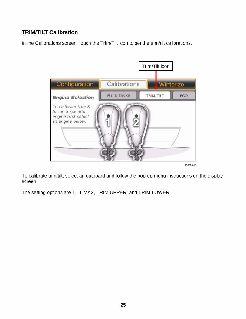
TRIM/TILT Calibration
In the Calibrations screen, touch the Trim/Tilt icon to set the trim/tilt calibrations.
To calibrate trim/tilt, select an outboard and follow the pop-up menu instructions on the display screen. The setting options are TILT MAX, TRIM UPPER, and TRIM LOWER.
Trim/Tilt icon
356595-16
25

ECO (Fuel Economy) Calibration
In the Calibrations feature, touch the ECO icon to set the ECO calibrations. Touch the Minus and Plus icons to change the number of seconds in the Fuel Economy calculation period. Touch the Reset icon to reset the Fuel Economy Long Term Average. Touch the Save icon to save the settings.
ECO icon
Minus and Plus icons
Reset icon Save icon
356595-17
26
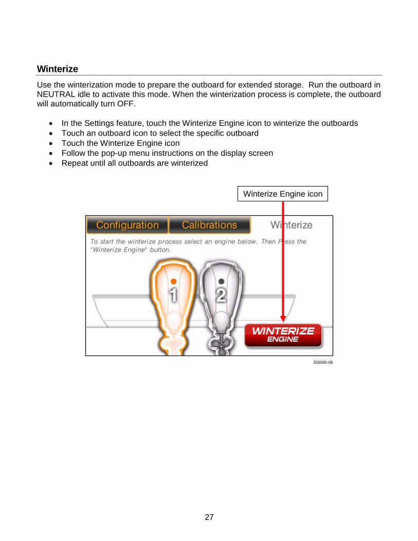
Winterize Use the winterization mode to prepare the outboard for extended storage. Run the outboard in NEUTRAL idle to activate this mode. When the winterization process is complete, the outboard will automatically turn OFF.
• In the Settings feature, touch the Winterize Engine icon to winterize the outboards • Touch an outboard icon to select the specific outboard • Touch the Winterize Engine icon • Follow the pop-up menu instructions on the display screen • Repeat until all outboards are winterized
Winterize Engine icon
356595-06
27
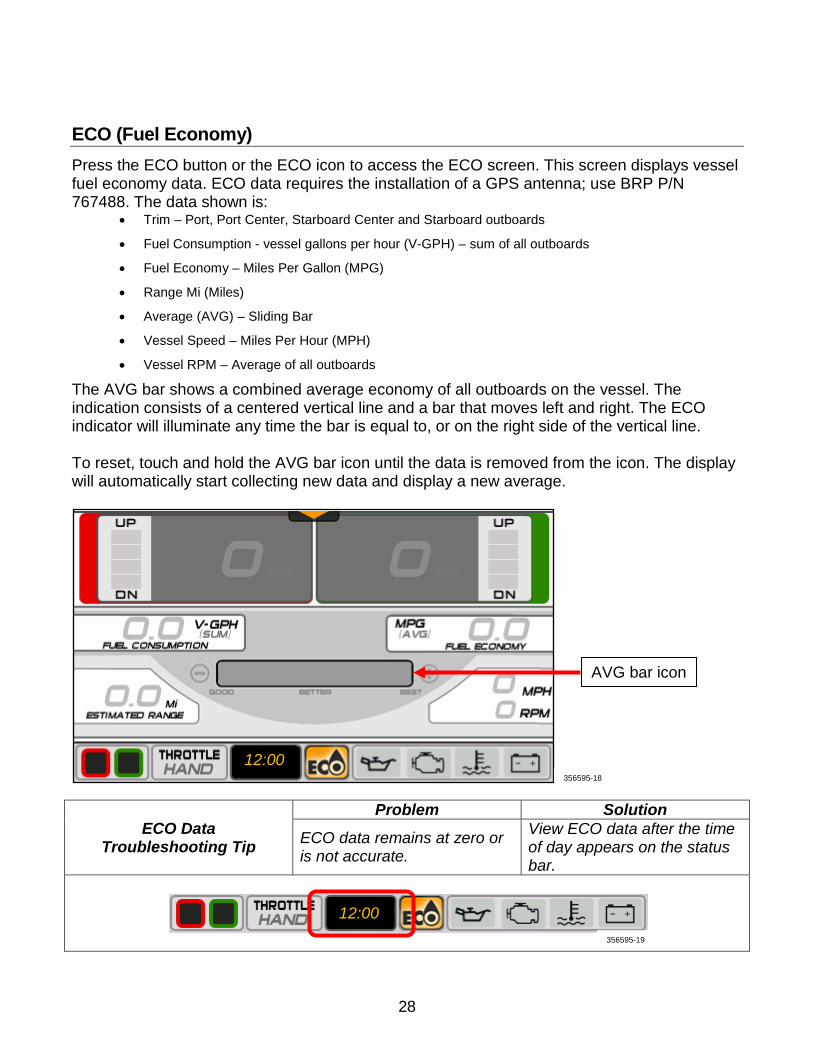
ECO (Fuel Economy) Press the ECO button or the ECO icon to access the ECO screen. This screen displays vessel fuel economy data. ECO data requires the installation of a GPS antenna; use BRP P/N 767488. The data shown is:
• Trim – Port, Port Center, Starboard Center and Starboard outboards
• Fuel Consumption - vessel gallons per hour (V-GPH) – sum of all outboards
• Fuel Economy – Miles Per Gallon (MPG)
• Range Mi (Miles)
• Average (AVG) – Sliding Bar
• Vessel Speed – Miles Per Hour (MPH)
• Vessel RPM – Average of all outboards
The AVG bar shows a combined average economy of all outboards on the vessel. The indication consists of a centered vertical line and a bar that moves left and right. The ECO indicator will illuminate any time the bar is equal to, or on the right side of the vertical line. To reset, touch and hold the AVG bar icon until the data is removed from the icon. The display will automatically start collecting new data and display a new average.
ECO Data Troubleshooting Tip
Problem Solution
ECO data remains at zero or is not accurate.
View ECO data after the time of day appears on the status bar.
AVG bar icon
356595-18
12:00
12:00 356595-19
28
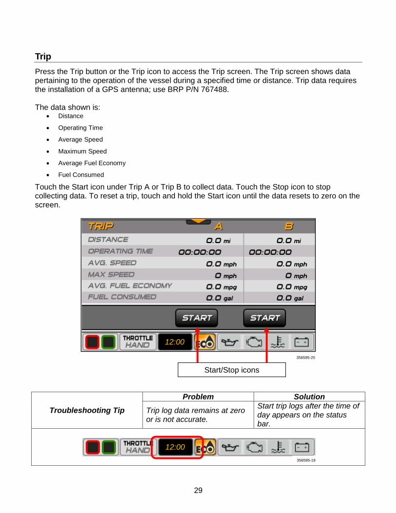
Trip Press the Trip button or the Trip icon to access the Trip screen. The Trip screen shows data pertaining to the operation of the vessel during a specified time or distance. Trip data requires the installation of a GPS antenna; use BRP P/N 767488. The data shown is:
• Distance
• Operating Time
• Average Speed
• Maximum Speed
• Average Fuel Economy
• Fuel Consumed
Touch the Start icon under Trip A or Trip B to collect data. Touch the Stop icon to stop collecting data. To reset a trip, touch and hold the Start icon until the data resets to zero on the screen.
Troubleshooting Tip
Problem Solution
Trip log data remains at zero or is not accurate.
Start trip logs after the time of day appears on the status bar.
Start/Stop icons
356595-20
12:00
12:00 356595-19
29
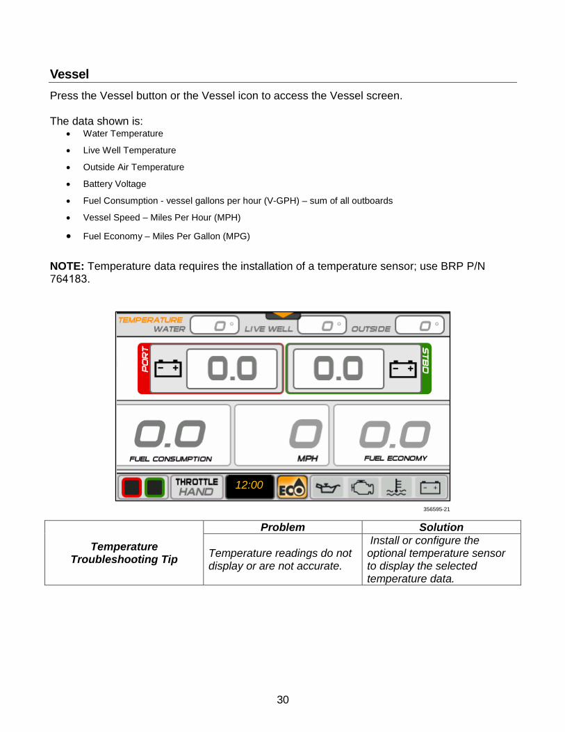
Vessel Press the Vessel button or the Vessel icon to access the Vessel screen.
The data shown is: • Water Temperature
• Live Well Temperature
• Outside Air Temperature
• Battery Voltage
• Fuel Consumption - vessel gallons per hour (V-GPH) – sum of all outboards
• Vessel Speed – Miles Per Hour (MPH)
• Fuel Economy – Miles Per Gallon (MPG)
NOTE: Temperature data requires the installation of a temperature sensor; use BRP P/N 764183.
Temperature Troubleshooting Tip
Problem Solution
Temperature readings do not display or are not accurate.
Install or configure the optional temperature sensor to display the selected temperature data.
356595-21
12:00
30
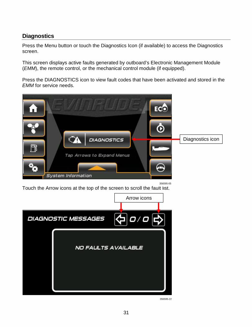
Diagnostics Press the Menu button or touch the Diagnostics Icon (if available) to access the Diagnostics screen. This screen displays active faults generated by outboard’s Electronic Management Module (EMM), the remote control, or the mechanical control module (if equipped). Press the DIAGNOSTICS icon to view fault codes that have been activated and stored in the EMM for service needs.
Touch the Arrow icons at the top of the screen to scroll the fault list.
Diagnostics icon
Arrow icons
356595-22
356595-05
31
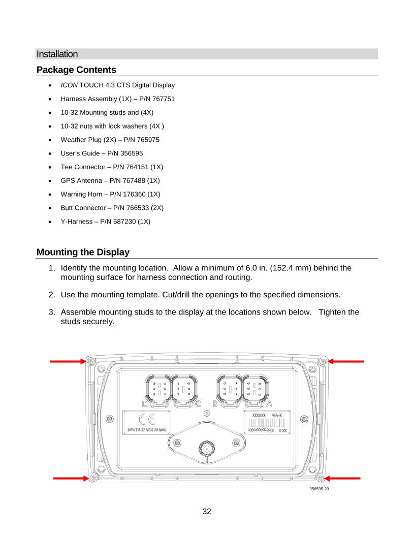
Installation Package Contents
• ICON TOUCH 4.3 CTS Digital Display
• Harness Assembly (1X) – P/N 767751
• 10-32 Mounting studs and (4X)
• 10-32 nuts with lock washers (4X )
• Weather Plug (2X) – P/N 765975
• User’s Guide – P/N 356595
• Tee Connector – P/N 764151 (1X)
• GPS Antenna – P/N 767488 (1X)
• Warning Horn – P/N 176360 (1X)
• Butt Connector – P/N 766533 (2X)
• Y-Harness – P/N 587230 (1X)
Mounting the Display 1. Identify the mounting location. Allow a minimum of 6.0 in. (152.4 mm) behind the
mounting surface for harness connection and routing.
2. Use the mounting template. Cut/drill the openings to the specified dimensions.
3. Assemble mounting studs to the display at the locations shown below. Tighten the studs securely.
356595-23
32
4. Place the display in the opening so the bezel is flush with the dashboard.
5. Use the nuts with lock washer to secure the display. Tighten the nuts securely.
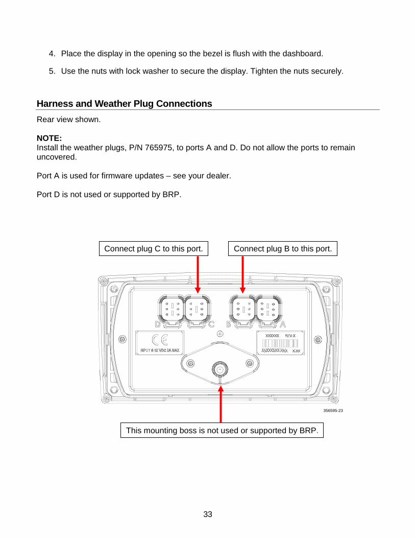
Harness and Weather Plug Connections Rear view shown. NOTE: Install the weather plugs, P/N 765975, to ports A and D. Do not allow the ports to remain uncovered. Port A is used for firmware updates – see your dealer. Port D is not used or supported by BRP.
Connect plug B to this port.
This mounting boss is not used or supported by BRP.
Connect plug C to this port.
356595-23
33
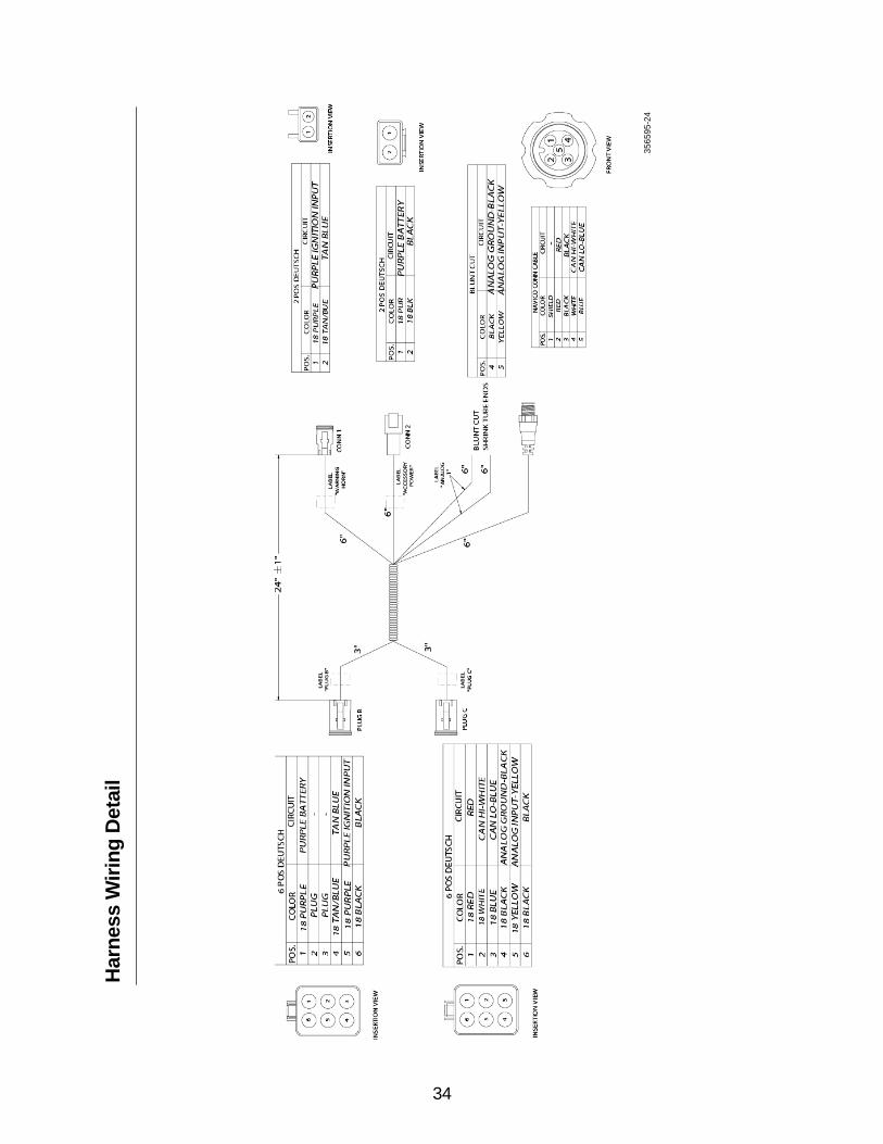
Har
ness
Wiri
ng D
etai
l
3565
95-2
4
34

35
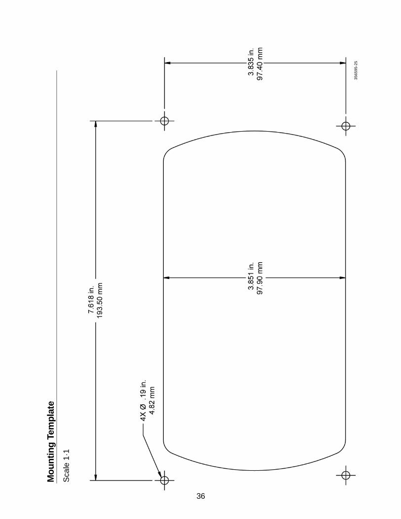
Mou
ntin
g Te
mpl
ate
Sca
le 1
·1
3565
95-2
5
36

©2014 Bombardier Recreational Products Inc. (BRP). All rights reserved. ®, TM and the BRP logo are trademarks of BRP or its affiliates.
*356595*Original