Embed Size (px)
Citation preview

BNI IOL-760-002-E066 IO-Link Version 1.1
RS232 to IO-Link Converter User´s Guide

www.balluff.com 1
Table of contents
1 General 3 1.1. Structure of the manual 3 1.2. Typographical conventions 3
Enumerations 3 Actions 3 Syntax 3 Cross-references 3
1.3. Symbols 3 1.4. Abbreviations 3 1.5. Deviating views 3
2 Safety 4 2.1. Proper use 4 2.2. Installation and startup 4 2.3. General safety instructions 4 2.4. Resistance to aggressive substances 4
Hazardous voltage 4 3 Getting Started 5
3.1. Connection overview 5 3.2. Electrical connection 6
IO-Link connection 6 Connecting the cable IO interface 6 Function earth 6 Module variants 6 RS232 connection 7
4 IO-Link Interface 8 IO-Link Data 8 Process Data / Input Data 8 Header Byte (00hex & 1Fhex) 8 Bit definition in Header Byte 8 Header (00hex & 1Fhex) 8 Number of Bytes / Error Code (01hex) 9 Error Codes 9 Data[0..29] (01hex –1Ehex) 9 Process Data / Output Data 10 Header Bytes (00hex & 1Fhex) 10 Bit definition in Header Bytes 10 Command Designator (01hex) 10 Number Of Bytes (02hex) 10 Data[0..29] (01hex –1Ehex) 10 Parameter Data / Demand Data 11 Parameter data / Demand data 11 RS232 Parameters 40hex 12 Enable Device Power Supply 45hex 12 Boot Cycle Counter 47hex 13 Device Temperature 52hex 13 Usage Hours Counter 57hex 13 Error Codes / Errors 14 Events 14
5 IO-Link Functions 15 IO-Link Version 1.1 15 Data Storage 15 Block Configuration 15 Restoring the Factory Settings 15
6 Device Functions 16 Start Up 16

www.balluff.com 2
Read 30 byte or less 16 Read more than 30 Byte 17 Write 30 byte or less 18 Write more than 30 Byte 19 Error occurred during command 20
7 Technical data 21 7.1. Dimensions 21 7.2. Mechanical data 21 7.3. Operating conditions 21 7.4. Electrical data 21
8 Function Indicators 22 Function Indicators 22 LED indicator module status 22
9 Appendix 23 9.1. Typ Code 23 9.2. Order information 23
Notes 24

Balluff Network Interface / IO-Link BNI IOL-760-002-E066
www.balluff.com 3
1 General
1.1. Structure of the manual
This manual is structured such that one chapter is builds on the other. Chapter 1: General Chapter 2: Basic safety instructions …….
1.2. Typographical
conventions The following typographical conventions are used in this manual.
Enumerations Enumeration is shown in the form of lists with bullets.
• Keyword 1 • Keyword 2
Actions Action instructions are indicated by a preceding triangle. The result of an action is indicated
by an arrow. Action instruction 1 Result of action Action instruction 2
Actions can also be indicated as numbers in parentheses. (1) Step 1 (2) Step 2 (3)
Syntax Numbers:
Decimal numbers are shown without additional information (e.g., 123), hexadecimal numbers are shown with the additional indicator hex (e.g., 00hex).
Cross-references Cross references indicate where further information on the subject can be found.
1.3. Symbols Note
This symbol indicates general notes. Attention!
This symbol indicates a safety instruction that must be followed without exception. 1.4. Abbreviations BNI
DPP I/O port IOL EMC FE LSB MSB SPDU
Balluff Network Interface Direct Parameter Page Digital input/output port IO-Link Electromagnetic compatibility Function earth Least Significant Bit Most Significant Bit Service Protocol Data Unit
1.5. Deviating views Product views and illustrations in this user's guide may differ from the actual product. They
are intended only as illustrative material.

www.balluff.com 4
2 Safety
2.1. Proper use The BNI IOL-760-002-E066 acts as a simple converter, which is between RS232 device and higher-level IO-Link master module through an IO-Link interface.
2.2. Installation and
startup Attention!
Installation and startup are to be performed only by trained specialists. Qualified personnel are persons who are familiar with the installation and operation of the product, and who fulfills the qualifications required for this activity. Any damage resulting from unauthorized manipulation or improper use voids the anufacturer's guarantee and warranty. The Operator is responsible for ensuring that applicable of safety and accident prevention regulations are complied with.
2.3. General safety
instructions Commissioning and inspection
Before commissioning, carefully read the operating manual. The system must not be used in applications in which the safety of persons is dependent on the function of the device. Authorized Personnel Installation and commissioning may only be performed by trained specialist personnel. Intended use Warranty and liability claims against the manufacturer are rendered void by:
• Unauthorized tampering • Improper use • Use, installation or handling contrary to the instructions provided in this operating
manual Obligations of the Operating Company The device is a piece of equipment from EMC Class A. Such equipment may generate RF noise. The operator must take appropriate precautionary measures. The device may only be used with an approved power supply. Only approved cables may be used. Malfunctions In the event of defects and device malfunctions that cannot be rectified, the device must be taken out of operation and protected against unauthorized use. Intended use is ensured only when the housing is fully installed.
2.4. Resistance to
aggressive substances
Attention! The BNI modules generally have a good chemical and oil resistance. When used in aggressive media (eg chemicals, oils, lubricants and coolants each in high concentration (ie, low water content)) must be checked prior application-related material compatibility. In the event of failure or damage to the BNI modules due to such aggressive media are no claims for defects.
Hazardous voltage
Attention! Disconnect all power before servicing equipment.
Note
In the interest of product improvement, the Balluff GmbH reserves the right to change the specifications of the product and the contents of this manual at any time without notice.

Balluff Network Interface / IO-Link BNI IOL-760-002-E066
www.balluff.com 5
3 Getting Started
3.1. Connection overview
Figure 1 – Connection overview BNI IOL-760-002-E066 1 IO-Link interface
2 Status LED: IO-Link communication status 3 Status LED: Sensor power Status 4 RS232 port

www.balluff.com 6
3 Getting Started
3.2. Electrical connection
The BNI IOL-760-002-E066 modules do not require a separate supply voltage connection. Supply voltage is provided via the IO-Link interface and the higher-level IO-Link master module.
IO-Link connection
The IO-Link connection is established via an M12 connector (A-coded, male). IO-Link (M12, A-coded, male)
Pin Requirement 1 Supply voltage for controller Us, +24 V 2 - 3 GND, reference potential 4 C/Q, IO-Link data transmission channel
Connecting the cable IO interface
Connect the incoming IO-Link cable to the RS232 to IO-Link Converter module.
Note
A standardized sensor cable is used to connect to the higher-level IO-Link master module. Maximum length of 20 m.
Function earth Note
The housing of the BNI IOL-760-002-E066 must be connected to the function earth and it must be low-impedance and kept as short as possible.
Module variants Variants Communication port
BNI IOL-760-002-E066 RS232

Balluff Network Interface / IO-Link BNI IOL-760-002-E066
www.balluff.com 7
3 Getting Started
RS232 connection The RS232 connection is established via an M12 connector (A-coded, female). The RS232 connection
Pin Functionality Description 1 TX RS232 - Transmit Data 2 RTS RS232 - Request To Send 3 RX RS232 - Receive Data 4 CTS RS232 - Clear To Send 5 DIN1 Digital Input 1 6 DIN2 Digital Input 2 7 +24V Supply voltage for RS232 device 8 GND Ground
Note
RS232 communication was specified in TIA/EIA-232-F standard.
Note For the digital inputs, the input guideline specified in EN 61131-2, Type 3 applies.
Note
Recommended is the use of the RS232 converter with the following devices: • Balluff Handheld-Barcode-Reader BVS HS-PC • Honeywell Barcode-Scanner 1900GSR-2
The use of this converter with other devices must be checked in advance for optimal functionality.
Note
The maximum data length which is allowed on the RS232 port is 255 bytes.

www.balluff.com 8
4 IO-Link Interface
IO-Link Data
* at minimum cycle time
BNI IOL-760-002-E066 Transfer rate COM2 (38.4 kbaud) Minimum cycle time 35 ms Process data length 32 bytes input, 32 bytes output IO-Link Revision 1.1 1.0 Frame typ 2.V 1 Process data cycle time* 35,2 ms 2240 ms
Note
It is recommended to use the BNI IOL-760-002-E066 with an IO-Link 1.1 master. In case of IO-Link 1.0 master, the process data cycle time will be extreme high.
Process Data / Input Data
Process data length of 32 byte:
Bit. no Subaddress 7 6 5 4 3 2 1 0
00hex – 1st header byte PW DIN2 TO DIN1 ER JE JA DA 01hex Number Of Bytes or Error Code or Data[0] 02hex-1Ehex Data[1] – Data[29] 1Fhex – 2nd header byte PW DIN2 TO DIN1 ER JE JA DA
Header Byte (00hex & 1Fhex)
Byte 0 Bit 7 6 5 4 3 2 1 0
Des
crip
tion
Pow
er (P
W)
Dig
ital I
nput
2 (D
IN2)
Togg
le B
it (T
O)
Dig
ital I
nput
1 (D
IN1)
Erro
r (ER
)
Job
End
(JE)
Job
Acce
pted
(JA)
Dat
a Av
aila
ble
(DA)
Bit definition in Header Byte
PW Power 1 = Device is ready 0 = Device is in reset state
DIN2 Digital Input 2 Indicates state of Digital Input 2
TO Toggle Bit TO flag is inverted if device is ready to read or write a new data block during a job
DIN1 Digital Input 1 Indicates state of Digital Input 1
ER Error 1 = Job incorrectly processed 0 = Job processed without error
JE Job End 1 = Job processed without error 0 = No job or job is running
JA Job Accepted 1 = The job was detected and accepted. 0 = No active job
DA Data Available 1 = New data received 0 = No input data
Header (00hex & 1Fhex)
If 1st and 2nd bit headers match, valid commands or data are present.
Balluff Network Interface / IO-Link BNI IOL-760-002-E066
www.balluff.com 9
4 IO-Link Interface
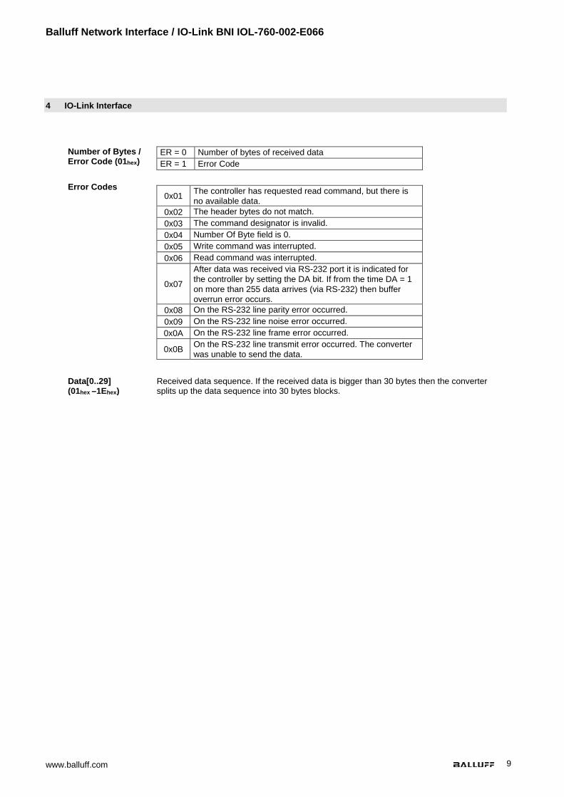
Number of Bytes / Error Code (01hex)
ER = 0 Number of bytes of received data ER = 1 Error Code
Error Codes
0x01 The controller has requested read command, but there is no available data.
0x02 The header bytes do not match. 0x03 The command designator is invalid. 0x04 Number Of Byte field is 0. 0x05 Write command was interrupted. 0x06 Read command was interrupted.
0x07
After data was received via RS-232 port it is indicated for the controller by setting the DA bit. If from the time DA = 1 on more than 255 data arrives (via RS-232) then buffer overrun error occurs.
0x08 On the RS-232 line parity error occurred. 0x09 On the RS-232 line noise error occurred. 0x0A On the RS-232 line frame error occurred.
0x0B On the RS-232 line transmit error occurred. The converter was unable to send the data.
Data[0..29] (01hex –1Ehex)
Received data sequence. If the received data is bigger than 30 bytes then the converter splits up the data sequence into 30 bytes blocks.

www.balluff.com 10
4 IO-Link Interface
Process Data / Output Data
Process data length of 32 byte:
Bit. no Subaddress 7 6 5 4 3 2 1 0
00hex – 1st header byte TI RD JB 01hex Command Designator or Data[0] 02hex Number of bytes or Data[1] 03hex-1Ehex Data[2] – Data[29] 1Fhex – 2nd header byte TI RD JB
Header Bytes (00hex & 1Fhex)
Byte 0 Bit 7 6 5 4 3 2 1 0
Des
crip
tion
Togg
le b
it (T
I)
Res
et D
evic
e (R
D)
Job
(JB)
Bit definition in Header Bytes
TI Toggle Bit TI flag is inverted if the controller is ready to read or write a new data block during a job.
RD Reset Device 1 = Software Reset 0 = Normal operation
JB Job 1 = New job pending 0 = No new job
Command Designator (01hex)
00hex – No Command 01hex – Reading Command 02hex – Writing Command
Number Of Bytes (02hex)
Number of bytes of data
Data[0..29] (01hex –1Ehex)
Sending data sequence. If the received data is bigger than 30 bytes then the controller splits up the data sequence into 30 bytes blocks.

Balluff Network Interface / IO-Link BNI IOL-760-002-E066
www.balluff.com 11
4 IO-Link Interface
Parameter Data / Demand Data
DPP SPDU Parameter Data width
Access rights
Default value Index Index Subindex
Iden
tific
atio
n da
ta
07hex Vendor ID 2 bytes
Rea
d on
ly
0378hex 08hex 09hex
Device ID 3 bytes 05 0E 01hex 0Ahex 0Bhex
10hex 0 Vendor name 8 bytes BALLUFF 11hex 0 Vendor text 16 bytes www.balluff.com
12hex 0 Product name
20/24 bytes BNI IOL-760-002-E066
13hex 0 Product ID 7 bytes BNI00C1
14hex 0 Product text 16 bytes RS232 to IO-Link Converter
15hex 0 Serial number 16 bytes 0hex
16hex 0 Hardware revision
17hex 0 Firmware revision
18hex 0 Application-
specific tag 32 bytes 0hex
Parameter data / Demand data
DPP SPDU Parameter Data width
Access rights Default Value Index Index Subindex
Para
met
er d
ata
40hex 64
0 1-4 RS232 Parameters 4 byte Read/write -
45hex 69 0 Enable External 24V 1 byte Read/write 0hex
47hex 71 0 Boot Counter 4 byte Read -
52hex 82
0 1-4 Temperature Data 5 byte Read -
57hex 87 0 Usage Hours Counter 12 bytes Read -

www.balluff.com 12
4 IO-Link Interface
RS232 Parameters 40hex
Byte 3 2 1 0 Sub-index 4 3 2 1
Des
crip
tion
Har
dwar
e Fl
ow C
ontro
l
RS2
32 F
ram
e Fo
rmat
Stop
Bit
Baud
Rat
e
Baud Rate:
0x00 – 9600 bit/s 0x01 – 19200 bit/s 0x02 – 38400 bit/s 0x03 – 57600 bit/s 0x04 – 115200 bit/s (default)
Stop Bit: 0x01 – 1 stop bit (default) 0x02 – 2 stop bit
RS232 Frame Format:
0x00 – 7 bit, Even 0x01 – 7 bit, Odd 0x02 – 8 bit, None (default) 0x03 – 8 bit, Even 0x04 – 8 bit, Odd 0x05 – 9 bit, None
Hardware Flow Control: 0x00 – Use RTS & CTS (default) 0x01 – Use RTS 0x02 – Use CTS 0x03 – None
Enable Device Power Supply 45hex
Byte 0 Bit 7 6 5 4 3 2 1 0
Sub-index 0
Des
crip
tion
Enab
le R
S232
Dev
ice
Pow
er
Supp
ly
Enable Device Power Supply:
0 – Disable RS232 device power supply (default) 1 – Enable RS232 device power supply

Balluff Network Interface / IO-Link BNI IOL-760-002-E066
www.balluff.com 13
4 IO-Link Interface
Boot Cycle Counter 47hex
Boot Cycle Counter counts the number of start-up.
Byte 3 2 1 0 Sub-index 0
Des
crip
tion
Boot
Cyc
le C
ount
er
Device Temperature 52hex
The device measures its temperature during it is powered. The device stores the minimum and maximum temperature values measured during life-time and since last start-up. The temperature value is stored as a signed 8 bit integer (from -128 ºC to 127 ºC), with 1 °C resolution. For example: 1Ehex = 30dec = 30 °C FDhex = -3dec = -3 °C
Byte 4 3 2 1 0 Sub-index 5 4 3 2 1
Des
crip
tion
Min
. Tem
pera
ture
Val
ue
Sinc
e Fi
rst S
tart
(ºC
)
Max
. Tem
pera
ture
Val
ue
Sinc
e Fi
rst S
tart
(ºC
)
Min
. Tem
pera
ture
Val
ue
Sinc
e La
st S
tart
(ºC
)
Max
. Tem
pera
ture
Val
ue
Sinc
e La
st S
tart
(ºC
)
Actu
al T
empe
ratu
re V
alue
(º
C)
Usage Hours Counter 57hex
The operating hours counter counts the number of usage hours during the lifetime of the device.
Byte 3 2 1 0 3 2 1 0 3 2 1 0 Sub-index 3 2 1
Des
crip
tion
Ope
ratin
g H
ours
Po
wer
Up
Ope
ratin
g H
ours
M
aint
enan
ce
Ope
ratin
g H
ours
Operating Hours – Operating hours of device. Not resettable.
Operating Hours Maintenance – Operating hours of device. Reset on system command. Commit Maintenance (A5hex). Operating Hours Power Up – Time in hours since power up.

www.balluff.com 14
4 IO-Link Interface
Error Codes / Errors
Error code Description 0x8011 Index not available 0x8012 Subindex not available 0x8023 Access denied 0x8030 Parameter value out of range 0x8033 Parameter length overrun 0x8034 Parameter length underrun 0x8035 Function not available
Events IO-Link Revision 1.0
Event code Description 0x5112 Low voltage (US) 0x4210 Temperature is over 55 °C 0x4220 Temperature is under -5 °C 0x7710 Short circuit
IO-Link Revision 1.1 Event code Description
0x5111 Low voltage (US) 0x4210 Temperature is over 55 °C 0x4220 Temperature is under -5 °C 0x7710 Short circuit

Balluff Network Interface / IO-Link BNI IOL-760-002-E066
www.balluff.com 15
5 IO-Link Functions
IO-Link Version 1.1
This device can be operated with an IO-Link master according to IO-Link version 1.1. Version-specific functions such as data storage (version 1.1) are only supported in combination with a suitable IO-Link master.
Data Storage Each IO-Link master of IO-Link version 1.1 features data storage in which an image of the
IO-Link device configuration can be stored. When a device is replaced, the stored configuration is automatically transferred to the new device. This guarantees minimal downtime. Validation must be switched on in order to use the data storage. For information about the configuration of data storage and validation, please refer to the operating manual of the respective IO-Link master.
Block Configuration
The device supports block configuration. This allows all parameters in a data block to be consistently imported from a controller or a configuration tool into the device.
Restoring the Factory Settings
The factory settings on the device can be restored by carrying out the "restore factory settings" system command. 0x82 must be written to Index 2 Subindex 0 for the command.

www.balluff.com 16
6 Device Functions
Start Up
PD Output Subaddress Command from
controller
PD Input Subaddres
s
Response from converter
00hex RD, JB = 0 00hex Set PW … … … …
1Fhex RD, JB = 0 1Fhex Set PW
Read 30 byte or less
Example 1: The controller reads out 30 bytes from the converter.
PD Output Subaddress
Command from controller
PD Input Subaddress
Response from converter
- 00hex Set DA
- 01hex Number Of Bytes = 1Ehex
… …
1Fhex Set DA
PD Output Subaddress
Command from controller
PD Input Subaddress
Response from converter
00hex Set JB 00hex Set JE, JA
01hex Command = 01hex 01hex-1Ehex Enter data … … 1Fhex Set JE, JA
1Fhex Set JB
PD Output
Subaddress Command from
controller PD Input
Subaddress Response from
converter 00hex Clear JB 00hex Clear DA, JE, JA
… … … …
1Fhex Clear JB 1Fhex Clear DA, JE, JA

Balluff Network Interface / IO-Link BNI IOL-760-002-E066
www.balluff.com 17
6 Device Functions
Read more than 30 Byte
Example 2: The controller reads out 64 bytes rom the converter.
PD Output Subaddress Command from controller PD Input
Subaddress Response from converter
- 00hex Set DA - 01hex Number Of Bytes = 40hex … … 1Fhex Set DA
PD Output Subaddress Command from controller
PD Input
Subaddress Response from converter
00hex Set JB 00hex Set JA 01hex Command = 01hex 01hex-1Ehex Enter the first 30 bytes of
data … … 1Fhex Set JB 1Fhex Set JA
PD Output
Subaddress Command from controller PD Input Subaddress Response from converter
00hex Invert TI 00hex Invert TO … … 01hex-1Ehex Enter the second 30
bytes of data 1Fhex Invert TI 1Fhex Invert TO
PD Output Subaddress Command from controller PD Input
Subaddress Response from converter
00hex Invert TI 00hex Invert TO, Set JE … … 01hex-04hex Enter the last 4 bytes of
data 1Fhex Invert TI … … 1Fhex Invert TO, Set JE
PD Output Subaddress Command from controller PD Input
Subaddress Response from converter
00hex Clear JB 00hex Clear DA, JE, JA, TO … … … …
1Fhex Clear JB 1Fhex Clear DA, JE, JA, TO

www.balluff.com 18
6 Device Functions
Write 30 byte or less
Example 3: The controller writes 30 bytes into the converter.
PD Output Subaddress Command from controller PD Input
Subaddress Response from
converter 00hex Set JB 00hex Set JA 01hex Command = 02hex … … 02hex Number Of Bytes = 1Ehex 1Fhex Set JA
… … 1Fhex Set JB
PD Output
Subaddress Command from controller PD Input Subaddress
Response from converter
00hex Invert TI 00hex Set JE 01hex-1Ehex Enter data … …
1Fhex Invert TI 1Fhex Set JE
PD Output Subaddress Command from controller PD Input
Subaddress Response from
converter 00hex Clear JB 00hex Clear JE, JA
… … … … 1Fhex Clear JB 1Fhex Clear JE, JA

Balluff Network Interface / IO-Link BNI IOL-760-002-E066
www.balluff.com 19
6 Device Functions
Write more than 30 Byte
Example 4: writing 64 byte.
PD Output Subaddress
Command from controller
PD Input Subaddress Response from converter
00hex Set JB 00hex Set JA 01hex Command = 02hex … … 02hex Number Of Byte = 40hex 1Fhex Set JA
… … 1Fhex Set JB
PD Output
Subaddress Command from
controller PD Input
Subaddress Response from converter
00hex Invert TI 00hex Invert TO
01hex-1Ehex Enter the first 30 bytes of data
… … 1Fhex Invert TO
1Fhex Invert TI
PD Output Subaddress
Command from controller
PD Input Subaddress Response from converter
00hex Invert TI 00hex Invert TO
01hex-1Ehex Enter the second 30 bytes of data
… … 1Fhex Invert TO
1Fhex Invert TI
PD Output Subaddress
Command from controller
PD Input Subaddress Response from converter
00hex Invert TI 00hex Set JE
01hex-04hex Enter the last 4 bytes of data
… … 1Fhex Set JE
… … 1Fhex Invert TI
PD Output
Subaddress Command from
controller PD Input
Subaddress Response from converter
00hex Clear JB 00hex Clear JE, JA, TO … … … …
1Fhex Clear JB 1Fhex Clear JE, JA, TO

www.balluff.com 20
6 Device Functions
Error occurred during command
Example 5: Error occurred during writing command.
PD Output Subaddress
Command from controller
PD Input Subaddress
Response from converter
00hex Set JB 00hex Set JA 01hex Command = 02hex … … 02hex Number Of Byte = 40hex 1Fhex Set JA
… … 1Fhex Set JB
PD Output
Subaddress Command from
controller PD Input
Subaddress Response from
converter 00hex Invert TI 00hex Set ER
01hex-1Ehex Enter the first 30 bytes of data
01hex Error Code … …
1Fhex Invert TI 1Fhex Set ER
PD Output Subaddress
Command from controller
PD Input Subaddress
Response from converter
00hex Set RD 00hex Clear PW (Header = 00hex)
… … 00hex – 1Ehex 00hex 1Fhex Set RD 1Fhex Clear PW (Header =
00hex)
PD Output Subaddress
Command from controller
PD Input Subaddress
Response from converter
00hex Clear RD 00hex Set PW … … … …
1Fhex Clear RD 1Fhex Set PW

Balluff Network Interface / IO-Link BNI IOL-760-002-E066
www.balluff.com 21
7 Technical data
7.1. Dimensions
7.2. Mechanical data Housing material Stainless steel
IO-Link port IO-Link port M12, A-coded, male, 4-pole
RS232 ports RS232 port M12, A-coded, female, 8-pole
Weight 100 g
Dimension (L × W, without connector) 118 × 18 mm
7.3. Operating
conditions Ambient temperature -5 °C … +55 °C
Storage temperature -25 °C … +70 °C
Degree of protection IP67 (only in plugged-in and screwed state)
7.4. Electrical data Supply voltage 18–30.2 V DC, corresponding to EN 61131-2
Ripple < 1%
Current consumption without load ≤ 65 mA
Current draw max. Max. 1,5 A (temperature-dependent)
Output current max. Max. 1,4 A (temperature-dependent)
Inputs PNP, type 3
www.balluff.com 22
8 Function Indicators
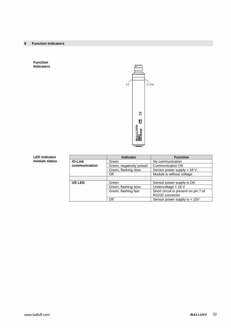
Function Indicators
LED indicator module status
Indicator Function IO-Link communication
Green No communication Green, negatively pulsed Communication OK Green, flashing slow Sensor power supply < 18 V Off Module is without voltage
US LED Green Sensor power supply is OK
Green, flashing slow Undervoltage < 18 V Green, flashing fast Short circuit is present on pin 7 of
RS232 connector Off Sensor power supply is < 15V

Balluff Network Interface / IO-Link BNI IOL-760-002-E066
www.balluff.com 23
9 Appendix
9.1. Typ Code
9.2. Order
information Product ordering code Ordering code
BNI IOL-760-002-E066 BNI00C1
BNI IOL-760-002-E066
Balluff Network Interface
IO-Link interface
Functions 760 = RS232 converter
Variants 002 = IO-Link version 1.1
Mechanical configuration E066 = Stainless steel tube housing

www.balluff.com 24
Notes

Balluff Network Interface / IO-Link BNI IOL-760-002-E066
www.balluff.com
www.balluff.com
Balluff GmbH Schurwaldstrasse 9 73765 Neuhausen a.d.F. Germany Tel. +49 7158 173-0 Fax +49 7158 5010 [email protected]
No.
935
387-
726
EN •
04.1
2715
1 •E
ditio
n I1
8 •R
epla
ces
Editi
on F
18 •
Subj
ect t
o m
odifi
catio
ns.