Embed Size (px)
Citation preview
User’sManual
Contents
1. Introduction1.1 For Safe Use of Product ..............................................21.2 Warranty ......................................................................31.3 ATEX Documentation ..................................................4
2. Handling Cautions2.1 ModelandSpecificationsCheck .................................62.2 SelectingtheInstallationLocation ..............................62.3 PressureConnection ..................................................62.4 InstallationofanExplosion-ProtectedInstrument ......62.5 EMCConformityStandards ..................................... 172.6 Pressure Equipment Directive (PED) ...................... 172.7 Safety Requirement Standards ................................ 18
3. Installation3.1 Mounting................................................................... 193.2 MountingtheDiaphragmSeals ......................................193.3 DiaphragmSealsInstallationConsideration ............ 203.4 MountingtheFlushingConnectionRing .................. 213.5 AffixingtheTeflonFilm ............................................. 223.6 Rotating Transmitter Section .................................... 233.7 ChangingtheDirectionofIntegralIndicator............. 23
4. Installing Impulse Piping4.1 ImpulsePipingInstallationPrecautions ................... 244.2 ImpulsePipingConnectionExamples ..................... 264.3 ProcessPipingInstallationPrecautions(EJ115) 27
5. Wiring5.1 Wiring Precautions ................................................... 295.2 ConnectionsofExternalWiringtoTerminalBox ...... 295.3 Wiring ....................................................................... 325.4 RTDCableConnection(EJX910A/EJX930A) ......... 345.5 Grounding ................................................................ 365.6 PowerSupplyVoltageandLoadResistance ........... 36
6. Operation6.1 Preparation for Starting Operation ........................... 376.2 Zero Point Adjustment .............................................. 386.3 LocalParameterSetting .......................................... 39
7. Errors and Countermeasures8. Parameter Summary
1
2
3
4
5
6
7
8
EJX and EJA-E SeriesDifferential Pressure and Pressure TransmittersInstallation Manual
IM01C25A01-01E
IM01C25A01-01E9thEdition
CD-ROM included
<1. Introduction> 1
IM01C25A01-01E9thEdition:Oct.2014(KP)AllRightsReserved,Copyright©2009,YokogawaElectricCorporation
1. IntroductionThankyouforpurchasingtheDPharpelectronicpressuretransmitter.
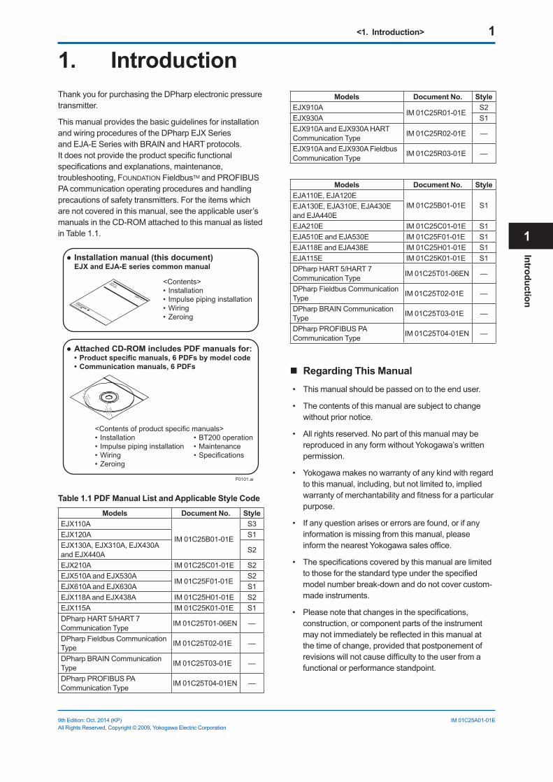
ThismanualprovidesthebasicguidelinesforinstallationandwiringproceduresoftheDPharpEJXSeriesandEJA-ESerieswithBRAINandHARTprotocols.Itdoesnotprovidetheproductspecificfunctionalspecificationsandexplanations,maintenance,troubleshooting,FOUNDATIONFieldbusTMandPROFIBUSPAcommunicationoperatingproceduresandhandlingprecautionsofsafetytransmitters.Fortheitemswhicharenotcoveredinthismanual,seetheapplicableuser’smanualsintheCD-ROMattachedtothismanualaslistedinTable1.1.
F0101.ai
Installation manual (this document) EJX and EJA-E series common manual
<Contents>• Installation• Impulse piping installation• Wiring• Zeroing
Attached CD-ROM includes PDF manuals for:• Product specific manuals, 6 PDFs by model code• Communication manuals, 6 PDFs
<Contents of product specific manuals>• Installation • BT200 operation• Impulse piping installation • Maintenance• Wiring • Specifications• Zeroing
Table 1.1 PDF Manual List and Applicable Style Code
Models Document No. StyleEJX110A
IM01C25B01-01E
S3EJX120A S1EJX130A,EJX310A,EJX430AandEJX440A S2
EJX210A IM01C25C01-01E S2EJX510AandEJX530A
IM01C25F01-01ES2
EJX610AandEJX630A S1EJX118AandEJX438A IM01C25H01-01E S2EJX115A IM01C25K01-01E S1DPharpHART5/HART7CommunicationType IM01C25T01-06EN —
DPharpFieldbusCommunicationType IM01C25T02-01E —
DPharpBRAINCommunicationType IM01C25T03-01E —
DPharpPROFIBUSPACommunicationType IM01C25T04-01EN —
Models Document No. StyleEJX910A
IM01C25R01-01ES2
EJX930A S1EJX910AandEJX930AHARTCommunicationType IM01C25R02-01E —
EJX910AandEJX930AFieldbusCommunicationType IM01C25R03-01E —
Models Document No. StyleEJA110E,EJA120E
IM01C25B01-01E S1EJA130E,EJA310E,EJA430EandEJA440EEJA210E IM01C25C01-01E S1EJA510EandEJA530E IM01C25F01-01E S1EJA118EandEJA438E IM01C25H01-01E S1EJA115E IM01C25K01-01E S1DPharpHART5/HART7CommunicationType IM01C25T01-06EN —
DPharpFieldbusCommunicationType IM01C25T02-01E —
DPharpBRAINCommunicationType IM01C25T03-01E —
DPharpPROFIBUSPACommunicationType IM01C25T04-01EN —
Regarding This Manual
• Thismanualshouldbepassedontotheenduser.
• Thecontentsofthismanualaresubjecttochangewithoutpriornotice.
• Allrightsreserved.NopartofthismanualmaybereproducedinanyformwithoutYokogawa’swrittenpermission.
• Yokogawamakesnowarrantyofanykindwithregardtothismanual,including,butnotlimitedto,impliedwarrantyofmerchantabilityandfitnessforaparticularpurpose.
• Ifanyquestionarisesorerrorsarefound,orifanyinformationismissingfromthismanual,pleaseinformthenearestYokogawasalesoffice.
• Thespecificationscoveredbythismanualarelimitedtothoseforthestandardtypeunderthespecifiedmodelnumberbreak-downanddonotcovercustom-made instruments.
• Pleasenotethatchangesinthespecifications,construction,orcomponentpartsoftheinstrumentmaynotimmediatelybereflectedinthismanualatthetimeofchange,providedthatpostponementofrevisionswillnotcausedifficultytotheuserfromafunctional or performance standpoint.
1
Introduction
<1. Introduction> 2
IM01C25A01-01E
• Yokogawaassumesnoresponsibilitiesforthisproductexceptasstatedinthewarranty.
• Ifthecustomeroranythirdpartyisharmedbytheuseofthisproduct,Yokogawaassumesnoresponsibilityforanysuchharmowingtoanydefectsintheproductwhichwerenotpredictable,orforanyindirectdamages.
• WhendescribingthemodelnamelikeEJ110 inthismanual,itshowstheapplicabilityforbothEJX110AandEJA110E.Thesamerepresentationsareusedfortheothermodels,too.
NOTEFor FOUNDATIONFieldbusandPROFIBUSPAprotocolversions,pleaserefertomanualsintheattachedCD-ROM,inadditiontothismanual.
• Thefollowingsafetysymbolmarksareusedinthismanual:
WARNING
Indicatesapotentiallyhazardoussituationwhich,ifnotavoided,couldresultindeathorseriousinjury.
CAUTIONIndicatesapotentiallyhazardoussituationwhich,ifnotavoided,mayresultinminorormoderateinjury.Itmayalsobeusedtoalertagainstunsafepractices.
IMPORTANTIndicatesthatoperatingthehardwareorsoftwareinthismannermaydamageitorleadtosystemfailure.
NOTEDraws attention to information essential for understandingtheoperationandfeatures.
Direct current
Functional grounding terminal
CautionThissymbolindicatesthattheoperatormustrefertoanexplanationintheuser’smanualinordertoavoidtheriskofinjuryordeathofpersonnelordamagetotheinstrument.
1.1 For Safe Use of ProductFortheprotectionandsafetyoftheoperatorandtheinstrumentorthesystemincludingtheinstrument,pleasebesuretofollowtheinstructionsonsafetydescribedinthismanualwhenhandlingthisinstrument.Incasetheinstrumentishandledincontradictiontotheseinstructions,Yokogawadoesnotguaranteesafety.Pleasegiveyourattentiontothefollowings.
(a) Installation
• Theinstrumentmustbeinstalledbyanexpertengineeroraskilledpersonnel.TheproceduresdescribedaboutINSTALLATIONarenotpermittedforoperators.
• Incaseofhighprocesstemperature,careshouldbetakennottoburnyourselfbecausethesurfaceofbodyandcasereachesahightemperature.
• Theinstrumentinstalledintheprocessisunderpressure.Neverloosentheprocessconnectorboltstoavoidthedangerousspoutingofprocessfluid.
• Duringdrainingcondensatefromthepressuredetectorsection,takeappropriatecaretoavoidcontactwiththeskin,eyesorbody,orinhalationofvapors,iftheaccumulatedprocessfluidmaybetoxicorotherwiseharmful.
• Whenremovingtheinstrumentfromhazardousprocesses,avoidcontactwiththefluidandtheinteriorofthemeter.
• Allinstallationshallcomplywithlocalinstallationrequirement and local electrical code.
(b) Wiring
• Theinstrumentmustbeinstalledbyanexpertengineeroraskilledpersonnel.TheproceduresdescribedaboutWIRINGarenotpermittedforoperators.
• Pleaseconfirmthatvoltagesbetweenthepowersupplyandtheinstrumentbeforeconnectingthepowercablesandthatthecablesarenotpoweredbeforeconnecting.
(c) Operation
• Wait5min.afterpoweristurnedoff,beforeopeningthecovers.
• Donotopenthecoverinwetweatherorhumidenvironment.Ifthecoverisopened,statedenclosureprotectionisnotapplicable.

<1. Introduction> 3
IM01C25A01-01E
(d) Maintenance
• Pleasedonotcarryoutexceptbeingwrittentomaintenancedescriptions.Whentheseproceduresareneeded,pleasecontactnearestYOKOGAWAoffice.
• Careshouldbetakentopreventthebuildupofdrift,dustorothermaterialonthedisplayglassandnameplate.Incaseofitsmaintenance,softanddryclothisused.
(e) Explosion Protected Type Instrument
• Usersofexplosionproofinstrumentsshouldreferfirsttosection2.4(InstallationofanExplosionProtectedInstrument)ofthismanual.
• Theuseofthisinstrumentisrestrictedtothosewhohavereceivedappropriatetraininginthedevice.
• Takecarenottocreatesparkswhenaccessingtheinstrumentorperipheraldevicesinahazardouslocation.
(f) Modification
• Yokogawawillnotbeliableformalfunctionsordamageresultingfromanymodificationmadetothisinstrumentbythecustomer.
1.2 Warranty• Thewarrantyshallcovertheperiodnotedonthe
quotationpresentedtothepurchaseratthetimeofpurchase.Problemsoccurredduringthewarrantyperiodshallbasicallyberepairedfreeofcharge.
• Incaseofproblems,thecustomershouldcontacttheYokogawarepresentativefromwhichtheinstrumentwaspurchased,orthenearestYokogawaoffice.
• Ifaproblemariseswiththisinstrument,pleaseinformusofthenatureoftheproblemandthecircumstancesunderwhichitdeveloped,includingthemodelspecificationandserialnumber.Anydiagrams,dataandotherinformationyoucanincludeinyourcommunicationwillalsobehelpful.
• ResponsiblepartyforrepaircostfortheproblemsshallbedeterminedbyYokogawabasedonourinvestigation.
• ThePurchasershallbeartheresponsibilityforrepaircosts,evenduringthewarrantyperiod,ifthemalfunctionisdueto:
- Improperand/orinadequatemaintenancebythepurchaser.
- Failureordamageduetoimproperhandling,useorstoragewhichisoutofdesignconditions.
- UseoftheproductinquestioninalocationnotconformingtothestandardsspecifiedbyYokogawa,orduetoimpropermaintenanceoftheinstallation location.
- FailureordamageduetomodificationorrepairbyanypartyexceptYokogawaoranapprovedrepresentativeofYokogawa.
- Malfunctionordamagefromimproperrelocationoftheproductinquestionafterdelivery.
- Reasonofforcemajeuresuchasfires,earthquakes,storms/floods,thunder/lightening,orothernaturaldisasters,ordisturbances,riots,warfare,orradioactivecontamination.
1
Introduction
<1. Introduction> 4
IM01C25A01-01E
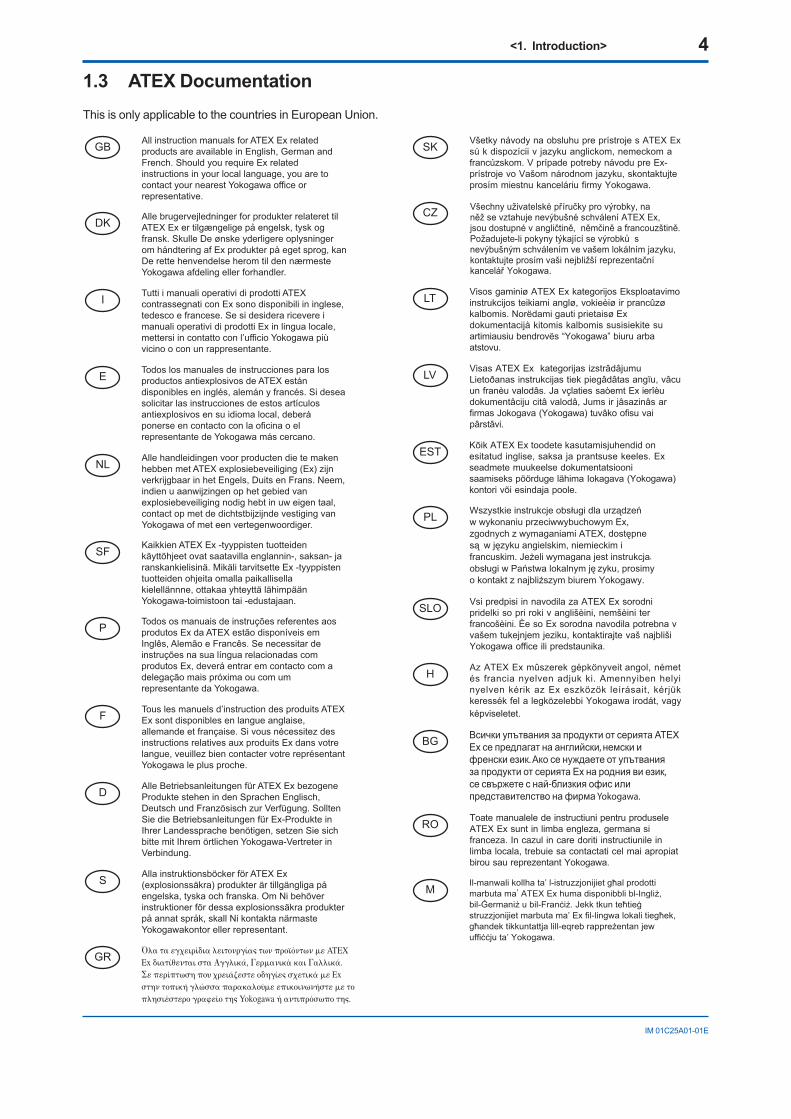
1.3 ATEX DocumentationThisisonlyapplicabletothecountriesinEuropeanUnion.
GB
DK
I
E
NL
SF
P
F
D
S
LT
LV
PL
EST
SLO
H
BG
RO
M
CZ
SK
GR
<2. Handling Cautions> 5
IM01C25A01-01E
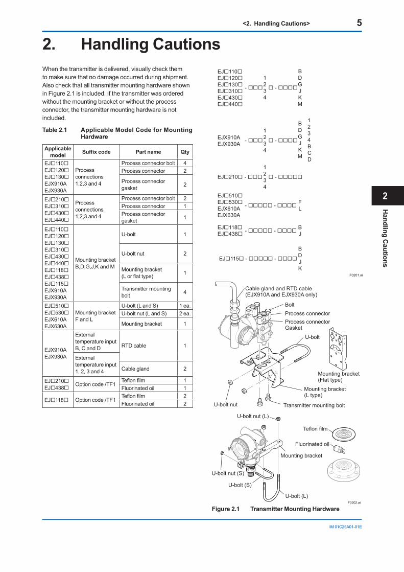
2. Handling CautionsWhenthetransmitterisdelivered,visuallycheckthemtomakesurethatnodamageoccurredduringshipment.AlsocheckthatalltransmittermountinghardwareshowninFigure2.1isincluded.Ifthetransmitterwasorderedwithoutthemountingbracketorwithouttheprocessconnector,thetransmittermountinghardwareisnotincluded.
Table 2.1 Applicable Model Code for Mounting Hardware
Applicable model Suffixcode Part name Qty
EJ110EJ120EJ130EJX910A EJX930A
Process connections 1,2,3and4
Processconnectorbolt 4Process connector 2
Process connector gasket 2
EJ210EJ310EJ430EJ440
Process connections 1,2,3and4
Processconnectorbolt 2Process connector 1Process connector gasket 1
EJ110EJ120EJ130EJ310EJ430EJ440EJ118EJ438EJ115EJX910A EJX930A
Mountingbracket B,D,G,J,KandM
U-bolt 1
U-boltnut 2
Mountingbracket (Lorflattype) 1
Transmitter mounting bolt 4
EJ510EJ530EJX610A EJX630A
Mountingbracket FandL
U-bolt(LandS) 1 ea.U-boltnut(LandS) 2 ea.
Mountingbracket 1
EJX910A EJX930A
Externaltemperature input B,CandD RTDcable 1
Externaltemperature input 1,2,3and4 Cablegland 2
EJ210EJ438 Optioncode/TF1
Teflonfilm 1Fluorinated oil 1
EJ118 Optioncode/TF1Teflonfilm 2Fluorinated oil 2
EJX910AEJX930A -
1234
1234BCD
-
BDGJKM
EJ110EJ120EJ130EJ310EJ430EJ440
-
1234
-
BDGJKM
- - BJ
EJ210
1234
- -
EJ510EJ530EJX610AEJX630A
EJ118EJ438
FL - -
F0201.ai
BDJK
EJ115 - -
Mounting bracket(Flat type)
F0202.ai
Teflon film
Fluorinated oil
BoltProcess connectorProcess connectorGasket
U-bolt nut
U-bolt
Mounting bracket(L type)
Transmitter mounting bolt
Cable gland and RTD cable(EJX910A and EJX930A only)
U-bolt nut (L)
Mounting bracket
U-bolt (L)
U-bolt (S)
U-bolt nut (S)
Figure 2.1 Transmitter Mounting Hardware
Handling C
autions
2
<2. Handling Cautions> 6
IM01C25A01-01E
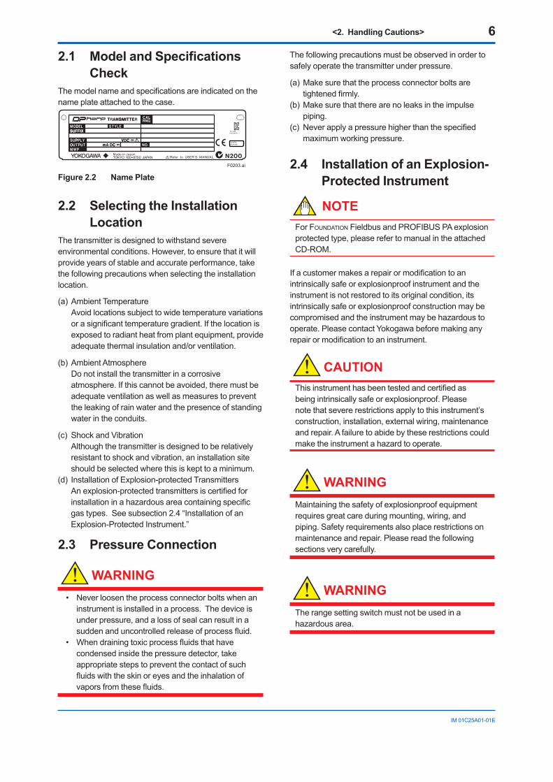
2.1 ModelandSpecificationsCheck
Themodelnameandspecificationsareindicatedonthenameplateattachedtothecase.
F0203.ai
Figure 2.2 Name Plate
2.2 Selecting the Installation Location
Thetransmitterisdesignedtowithstandsevereenvironmentalconditions.However,toensurethatitwillprovideyearsofstableandaccurateperformance,takethefollowingprecautionswhenselectingtheinstallationlocation.
(a)AmbientTemperatureAvoidlocationssubjecttowidetemperaturevariationsorasignificanttemperaturegradient.Ifthelocationisexposedtoradiantheatfromplantequipment,provideadequatethermalinsulationand/orventilation.
(b)AmbientAtmosphere Donotinstallthetransmitterinacorrosive
atmosphere.Ifthiscannotbeavoided,theremustbeadequate ventilation as well as measures to prevent theleakingofrainwaterandthepresenceofstandingwaterintheconduits.
(c)ShockandVibration Althoughthetransmitterisdesignedtoberelatively
resistanttoshockandvibration,aninstallationsiteshouldbeselectedwherethisiskepttoaminimum.
(d)InstallationofExplosion-protectedTransmitters Anexplosion-protectedtransmittersiscertifiedfor
installationinahazardousareacontainingspecificgastypes.Seesubsection2.4“InstallationofanExplosion-ProtectedInstrument.”
2.3 Pressure Connection
WARNING
• Neverloosentheprocessconnectorboltswhenaninstrumentisinstalledinaprocess.Thedeviceisunderpressure,andalossofsealcanresultinasuddenanduncontrolledreleaseofprocessfluid.
• Whendrainingtoxicprocessfluidsthathavecondensedinsidethepressuredetector,takeappropriatestepstopreventthecontactofsuchfluidswiththeskinoreyesandtheinhalationofvaporsfromthesefluids.
Thefollowingprecautionsmustbeobservedinordertosafelyoperatethetransmitterunderpressure.
(a)Makesurethattheprocessconnectorboltsaretightenedfirmly.
(b)Makesurethattherearenoleaksintheimpulsepiping.
(c) Neverapplyapressurehigherthanthespecifiedmaximumworkingpressure.
2.4 Installation of an Explosion-Protected Instrument
NOTEFor FoundationFieldbusandPROFIBUSPAexplosionprotectedtype,pleaserefertomanualintheattachedCD-ROM.
Ifacustomermakesarepairormodificationtoanintrinsicallysafeorexplosionproofinstrumentandtheinstrumentisnotrestoredtoitsoriginalcondition,itsintrinsicallysafeorexplosionproofconstructionmaybecompromisedandtheinstrumentmaybehazardoustooperate.PleasecontactYokogawabeforemakinganyrepairormodificationtoaninstrument.
CAUTIONThisinstrumenthasbeentestedandcertifiedasbeingintrinsicallysafeorexplosionproof.Pleasenotethatsevererestrictionsapplytothisinstrument’sconstruction,installation,externalwiring,maintenanceandrepair.Afailuretoabidebytheserestrictionscouldmaketheinstrumentahazardtooperate.
WARNING
Maintainingthesafetyofexplosionproofequipmentrequiresgreatcareduringmounting,wiring,andpiping. Safety requirements also place restrictions on maintenanceandrepair.Pleasereadthefollowingsections very carefully.
WARNING
Therangesettingswitchmustnotbeusedinahazardousarea.
<2. Handling Cautions> 7
IM01C25A01-01E
IMPORTANTForcombinedapprovaltypesOnceadeviceofmultipleapprovaltypeisinstalled,itshouldnotbere-installedusinganyotherapprovaltypes.Applyapermanentmarkinthecheckboxoftheselectedapprovaltypeonthecertificationlabelonthetransmittertodistinguishitfromunusedapprovaltypes.
2.4.1 FM Approval
a. FM Intrinsically Safe Type
CautionforFMintrinsicallysafetype.(Followingcontentsrefer“DOC.No.IFM022-A12”)
Note1. ModelEJX/EJA-ESeriesDifferential,gaugeandabsolutepressuretransmitterswithoptionalcode/FS1areapplicableforuseinhazardouslocations.
• ApplicableStandard:FM3600,FM3610,FM3611,FM3810
• IntrinsicallySafeforClassI,Division1,GroupsA,B,C&D.ClassII,Division1,GroupsE,F&GandClassIII,Division1,ClassI,Zone0inHazardousLocations,AExiaIIC
• NonincendiveforClassI,Division2,GroupsA,B,C&D.ClassII,Division2,GroupsF&GandClassI,Zone2,GroupsIIC,inHazardousLocations.
• Outdoorhazardouslocations:NEMATYPE4X• TemperatureClass:T4• Ambienttemperature:–60to60°C
Note2. EntityParameters• IntrinsicallySafeApparatusParameters [GroupsA,B,C,D,E,FandG]
Vmax=30V Ci=6nFImax=200mA Li=0µHPmax=1W
* Associated Apparatus Parameters (FMapprovedbarriers)
Voc≤30V Ca>6nFIsc≤200mA La>0µHPmax≤1W
• IntrinsicallySafeApparatusParameters [GroupsC,D,E,FandG]
Vmax=30V Ci=6nFImax=225mA Li=0µHPmax=1W
* Associated Apparatus Parameters (FMapprovedbarriers)
Voc≤30V Ca>6nFIsc≤225mA La>0µHPmax≤1W
• EntityInstallationRequirements Vmax≥VocorUoorVt,Imax≥IscorIoorIt, Pmax(orPo)≤Pi,CaorCo≥Ci+Ccable, LaorLo≥Li+Lcable
Note3. Installation• Barriermustbeinstalledinanenclosurethat
meetstherequirementsofANSI/ISAS82.01.• Controlequipmentconnectedtobarriermustnot
useorgeneratemorethan250VrmsorVdc.• InstallationshouldbeinaccordancewithANSI/ISA
RP12.6“InstallationofIntrinsicallySafeSystemsforHazardous(Classified)Locations”andtheNationalElectricCode(ANSI/NFPA70).
• TheconfigurationofassociatedapparatusmustbeFMRCApproved.
• Dust-tightconduitsealmustbeusedwheninstalledinaClassII,III,GroupE,FandGenvironments.
• Associatedapparatusmanufacturer’sinstallationdrawingmustbefollowedwheninstallingthisapparatus.
• Themaximumpowerdeliveredfromthebarriermustnotexceed1W.
• Noteawarninglabelworded“SUBSTITUTIONOFCOMPONENTSMAYIMPAIRINTRINSICSAFETY,”and“INSTALLINACCORDANCEWITHDOC.No.IFM022-A12”
Note4. MaintenanceandRepair• Theinstrumentmodificationorpartsreplacement
byotherthanauthorizedrepresentativeofYokogawaElectricCorporationisprohibitedandwillvoidFactoryMutualIntrinsicallysafeandNonincendiveApproval.
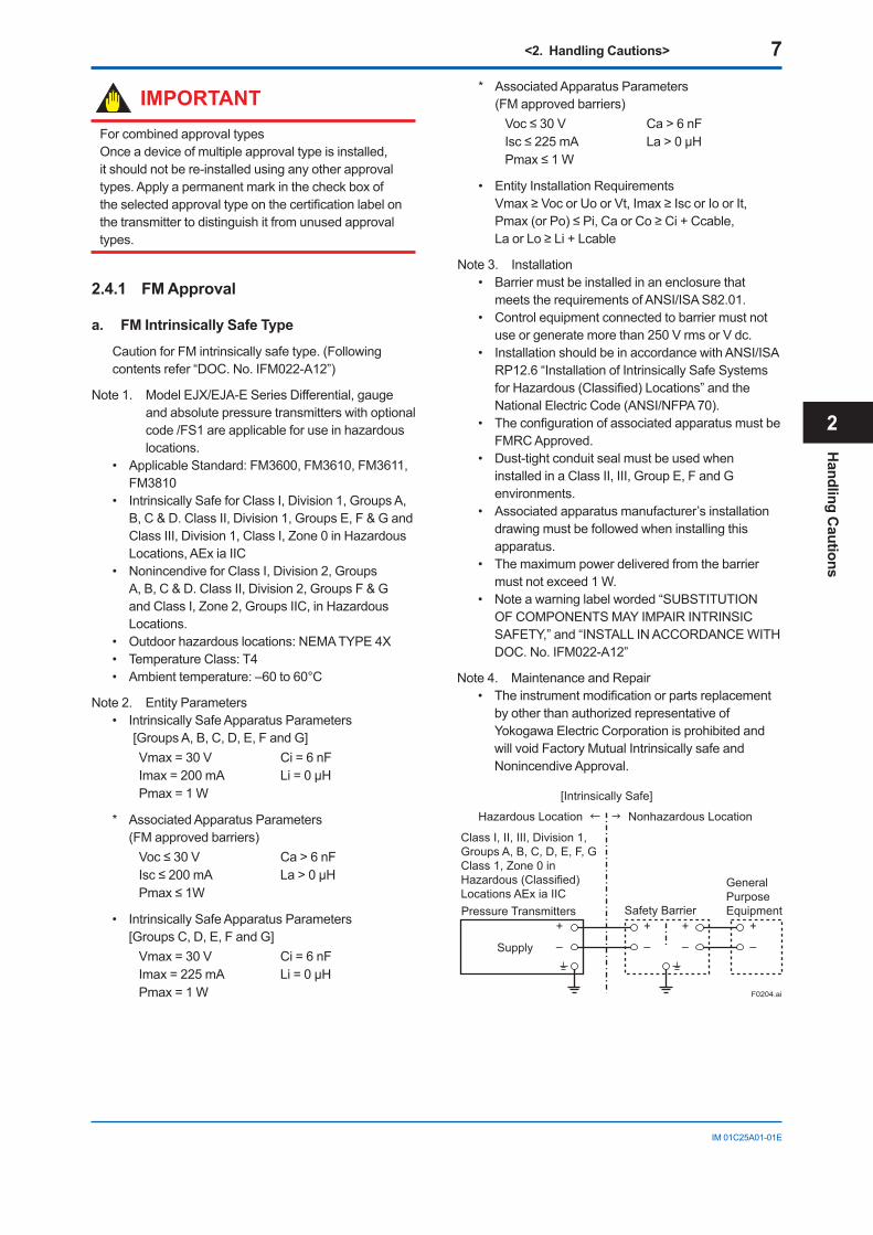
F0204.ai
Class I, II, III, Division 1,Groups A, B, C, D, E, F, GClass 1, Zone 0 in Hazardous (Classified) Locations AEx ia IICPressure Transmitters Safety Barrier
Supply
Hazardous Location Nonhazardous Location
General PurposeEquipment
+
–
+
–
+
–
+
–
[Intrinsically Safe]
Handling C
autions
2
<2. Handling Cautions> 8
IM01C25A01-01E
F0205.ai
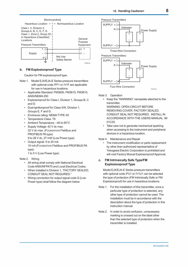
Pressure Transmitters
Supply
Hazardous Location Nonhazardous Location
+
–
+
–
Class I, II, Division 2,Groups A, B, C, D, F, GClass 1, Zone 2, Group IIC,in Hazardous (Classified)Locations
Not UseSafety Barrier
[Nonincendive]
General PurposeEquipment
b. FM Explosionproof Type
CautionforFMexplosionprooftype.
Note1. ModelEJX/EJA-ESeriespressuretransmitterswithoptionalcode/FF1or/V1Fareapplicableforuseinhazardouslocations.
• ApplicableStandard:FM3600,FM3615,FM3810,ANSI/NEMA250
• ExplosionproofforClassI,Division1,GroupsB,Cand D.
• Dust-ignitionproofforClassII/III,Division1,GroupsE,FandG.
• Enclosurerating:NEMATYPE4X• TemperatureClass:T6• AmbientTemperature:–40to60°C• SupplyVoltage:42Vdcmax.
32Vdcmax.(FOUNDATIONFieldbusandPROFIBUSPAtype)9to28Vdc,27mW(LowPowertype)
• Outputsignal:4to20mA15 mA (FOUNDATIONFieldbusandPROFIBUSPAtype)1to5V(LowPowertype)
Note2. Wiring• AllwiringshallcomplywithNationalElectrical
CodeANSI/NFPA70andLocalElectricalCodes.• WheninstalledinDivision1,“FACTORYSEALED,
CONDUITSEALNOTREQUIRED.”• WiringconnectionforoutputsignalcodeQ(Low
Powertype)shallfollowthediagrambelow.
F0218.ai
Three-Wire Connection
Pressure Transmitters
Power SupplyVoltmeter
SUPPLY +
SUPPLY –
A
+
–
+
–
Four-Wire Connection
Pressure Transmitters
Power SupplyVoltmeter
SUPPLY +
SUPPLY –
A
+
–
+
–
Note3. Operation• Keepthe“WARNING”nameplateattachedtothe
transmitter. WARNING:OPENCIRCUITBEFORE
REMOVINGCOVER.FACTORYSEALED,CONDUITSEALNOTREQUIRED.INSTALLINACCORDANCEWITHTHEUSERSMANUALIM01C25.
• Takecarenottogeneratemechanicalsparkingwhenaccessingtotheinstrumentandperipheraldevicesinahazardouslocation.
Note4. MaintenanceandRepair• Theinstrumentmodificationorpartsreplacement
byotherthanauthorizedrepresentativeofYokogawaElectricCorporationisprohibitedandwillvoidFactoryMutualExplosionproofApproval.
c. FM Intrinsically Safe Type/FM Explosionproof Type
ModelEJX/EJA-ESeriespressuretransmitterswithoptionalcode/FU1or/V1U1canbeselectedthetypeofprotection(FMIntrinsicallySafeorFMExplosionproof)foruseinhazardouslocations.
Note1. Fortheinstallationofthistransmitter,onceaparticulartypeofprotectionisselected,anyothertypeofprotectioncannotbeused.Theinstallationmustbeinaccordancewiththedescriptionaboutthetypeofprotectioninthisinstruction manual.
Note2. Inordertoavoidconfusion,unnecessarymarkingiscrossedoutonthelabelotherthantheselectedtypeofprotectionwhenthetransmitter is installed.
<2. Handling Cautions> 9
IM01C25A01-01E
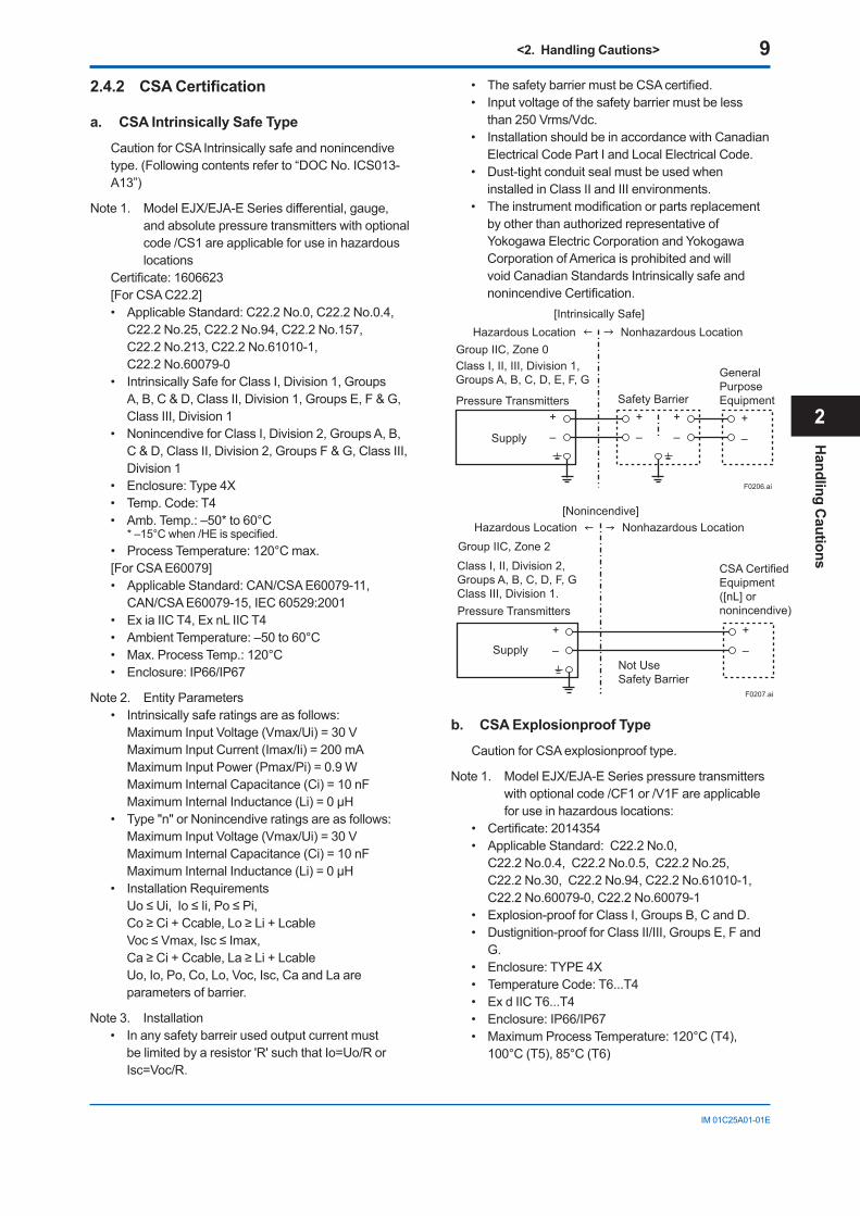
2.4.2 CSACertification
a. CSA Intrinsically Safe Type
CautionforCSAIntrinsicallysafeandnonincendivetype.(Followingcontentsreferto“DOCNo.ICS013-A13”)
Note1. ModelEJX/EJA-ESeriesdifferential,gauge,andabsolutepressuretransmitterswithoptionalcode/CS1areapplicableforuseinhazardouslocations
Certificate:1606623[ForCSAC22.2]• ApplicableStandard:C22.2No.0,C22.2No.0.4,
C22.2No.25,C22.2No.94,C22.2No.157, C22.2No.213,C22.2No.61010-1, C22.2No.60079-0
• IntrinsicallySafeforClassI,Division1,GroupsA,B,C&D,ClassII,Division1,GroupsE,F&G,ClassIII,Division1
• NonincendiveforClassI,Division2,GroupsA,B,C&D,ClassII,Division2,GroupsF&G,ClassIII,Division 1
• Enclosure:Type4X• Temp.Code:T4• Amb.Temp.:–50*to60°C *–15°Cwhen/HEisspecified.• ProcessTemperature:120°Cmax.[ForCSAE60079]• ApplicableStandard:CAN/CSAE60079-11,
CAN/CSAE60079-15,IEC60529:2001• ExiaIICT4,ExnLIICT4• AmbientTemperature:–50to60°C• Max.ProcessTemp.:120°C• Enclosure:IP66/IP67
Note2. EntityParameters• Intrinsicallysaferatingsareasfollows: MaximumInputVoltage(Vmax/Ui)=30V MaximumInputCurrent(Imax/Ii)=200mA MaximumInputPower(Pmax/Pi)=0.9W MaximumInternalCapacitance(Ci)=10nF MaximumInternalInductance(Li)=0µH• Type"n"orNonincendiveratingsareasfollows: MaximumInputVoltage(Vmax/Ui)=30V MaximumInternalCapacitance(Ci)=10nF MaximumInternalInductance(Li)=0µH• InstallationRequirements Uo≤Ui,Io≤Ii,Po≤Pi, Co≥Ci+Ccable,Lo≥Li+Lcable Voc≤Vmax,Isc≤Imax, Ca≥Ci+Ccable,La≥Li+Lcable Uo,Io,Po,Co,Lo,Voc,Isc,CaandLaare
parametersofbarrier.
Note3. Installation• Inanysafetybarreirusedoutputcurrentmust
belimitedbyaresistor'R'suchthatIo=Uo/RorIsc=Voc/R.
• ThesafetybarriermustbeCSAcertified.• Inputvoltageofthesafetybarriermustbeless
than250Vrms/Vdc.• InstallationshouldbeinaccordancewithCanadian
ElectricalCodePartIandLocalElectricalCode.• Dust-tightconduitsealmustbeusedwhen
installedinClassIIandIIIenvironments.• Theinstrumentmodificationorpartsreplacement
byotherthanauthorizedrepresentativeofYokogawaElectricCorporationandYokogawaCorporationofAmericaisprohibitedandwillvoidCanadianStandardsIntrinsicallysafeandnonincendiveCertification.
F0206.ai
Class I, II, III, Division 1,Groups A, B, C, D, E, F, G
Pressure Transmitters Safety Barrier
Supply
Hazardous Location Nonhazardous Location
General PurposeEquipment
+
–
+
–
+
– +
–
[Intrinsically Safe]
Group IIC, Zone 0
F0207.ai
Pressure Transmitters
Supply
Hazardous Location Nonhazardous Location
+
–
+
–
Class I, II, Division 2,Groups A, B, C, D, F, GClass III, Division 1.
Not UseSafety Barrier
[Nonincendive]
CSA Certified Equipment([nL] or nonincendive)
Group IIC, Zone 2
b. CSA Explosionproof Type
CautionforCSAexplosionprooftype.
Note1. ModelEJX/EJA-ESeriespressuretransmitterswithoptionalcode/CF1or/V1Fareapplicableforuseinhazardouslocations:
• Certificate:2014354• ApplicableStandard:C22.2No.0,
C22.2No.0.4,C22.2No.0.5,C22.2No.25, C22.2No.30,C22.2No.94,C22.2No.61010-1,C22.2No.60079-0,C22.2No.60079-1
• Explosion-proofforClassI,GroupsB,CandD.• Dustignition-proofforClassII/III,GroupsE,Fand
G.• Enclosure:TYPE4X• TemperatureCode:T6...T4• ExdIICT6...T4• Enclosure:IP66/IP67• MaximumProcessTemperature:120°C(T4),
100°C(T5),85°C(T6)
Handling C
autions
2
<2. Handling Cautions> 10
IM01C25A01-01E
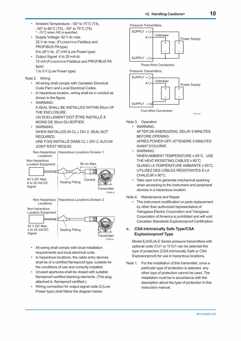
• AmbientTemperature:–50*to75°C(T4),–50*to80°C(T5),–50*to75°C(T6)
*–15°Cwhen/HEisspecified.• SupplyVoltage:42Vdcmax.
32Vdcmax.(FOUNDATIONFieldbusandPROFIBUSPAtype)9to28Vdc,27mW(LowPowertype)
• OutputSignal:4to20mAdc15 mA (FOUNDATIONFieldbusandPROFIBUSPAtype)1to5V(LowPowertype)
Note2. Wiring• AllwiringshallcomplywithCanadianElectrical
CodePartIandLocalElectricalCodes.• Inhazardouslocation,wiringshallbeinconduitas
showninthefigure.• WARNING: ASEALSHALLBEINSTALLEDWITHIN50cmOF
THEENCLOSURE. UNSCELLEMENTDOITÊTREINSTALLÉÀ
MOINSDE50cmDUBOÎTIER.• WARNING: WHENINSTALLEDINCL.I,DIV2,SEALNOT
REQUIRED. UNEFOISINSTALLÉDANSCLI,DIV2,AUCUN
JOINTN'ESTREQUIS.
Non-hazardous Location Equipment
42 V DC Max. 4 to 20 mA DC Signal
Non-Hazardous Locations
Hazardous Locations Division 1
50 cm Max.
Sealing FittingConduit
TransmitterF0208.ai
Non-Hazardous Locations
Hazardous Locations Division 2
Non-hazardous Location Equipment
42 V DC Max. 4 to 20 mA DC Signal
Sealing Fitting
TransmitterF0209.ai
• Allwiringshallcomplywithlocalinstallationrequirements and local electrical code.
• Inhazardouslocations,thecableentrydevicesshallbeofacertifiedflameprooftype,suitablefortheconditionsofuseandcorrectlyinstalled.
• Unusedaperturesshallbeclosedwithsuitableflameproofcertifiedblankingelements.(Theplugattachedisflameproofcertified.)
• WiringconnectionforoutputsignalcodeQ(LowPowertype)shallfollowthediagrambelow.
F0219.ai
Three-Wire Connection
Pressure Transmitters
Power SupplyVoltmeter
SUPPLY +
SUPPLY –
A
+
–
+
–
Four-Wire Connection
Pressure Transmitters
Power SupplyVoltmeter
SUPPLY +
SUPPLY –
A
+
–
+
–
Note3. Operation• WARNING: AFTERDE-ENERGIZING,DELAY5MINUTES
BEFOREOPENING. APRÉSPOWER-OFF,ATTENDRE5MINUTES
AVANTD'OUVRIR.• WARNING: WHENAMBIENTTEMPERATURE≥65°C,USE
THEHEAT-RESISTINGCABLES≥90°C. QUANDLATEMPÉRATUREAMBIANTE≥65°C,
UTILISEZDESCÂBLESRÉSISTANTESÁLACHALEUR≥90°C.
• Takecarenottogeneratemechanicalsparkingwhenaccessingtotheinstrumentandperipheraldevicesinahazardouslocation.
Note4. MaintenanceandRepair• Theinstrumentmodificationorpartsreplacement
byotherthanauthorizedrepresentativeofYokogawaElectricCorporationandYokogawaCorporationofAmericaisprohibitedandwillvoidCanadianStandardsExplosionproofCertification.
c. CSA Intrinsically Safe Type/CSA Explosionproof Type
ModelEJX/EJA-ESeriespressuretransmitterswithoptionalcode/CU1or/V1U1canbeselectedthetypeofprotection(CSAIntrinsicallySafeorCSAExplosionproof)foruseinhazardouslocations.
Note1. Fortheinstallationofthistransmitter,onceaparticulartypeofprotectionisselected,anyothertypeofprotectioncannotbeused.Theinstallationmustbeinaccordancewiththedescriptionaboutthetypeofprotectioninthisinstruction manual.
<2. Handling Cautions> 11
IM01C25A01-01E
Note2. Inordertoavoidconfusion,unnecessarymarkingiscrossedoutonthelabelotherthantheselectedtypeofprotectionwhenthetransmitter is installed.
2.4.3 ATEXCertification
(1) Technical Data
a. ATEX Intrinsically Safe Type (Except for EJX90A)
CautionforATEXIntrinsicallysafetype.
Note1. ModelEJX/EJA-ESeriespressuretransmitterswithoptionalcode/KS21forpotentiallyexplosiveatmospheres:
• No.DEKRA11ATEX0228X• ApplicableStandard:
EN60079-0:2009,EN60079-11:2007, EN60079-26:2007,EN61241-11:2006
• TypeofProtectionandMarkingcode:ExiaIICT4Ga
ExiaIIICT85ºCT100ºCT120ºCDb• Group:II• Category:1G,2D• AmbientTemperatureforEPLGa:
–50to60°C• AmbientTemperatureforEPLDb:
–30*to60°C*–15°Cwhen/HEisspecified.
• ProcessTemperature(Tp.):120°Cmax.• MaximumSurfaceTemperatureforEPLDb:
T85°C(Tp.:80°C) T100°C(Tp.:100°C) T120°C(Tp.:120°C)
• Enclosure:IP66/IP67
Note2 ElectricalData• IntypeofexplosionprotectionintrinsicsafetyExia
IICorExiaIIIC,onlyforconnectiontoacertifiedintrinsicallysafecircuitwithfollowingmaximumvalues:
Ui=30V Ii=200mA Pi=0.9W (LinearSource) Maximuminternalcapacitance;Ci=27.6nF Maximuminternalinductance;Li=0µH
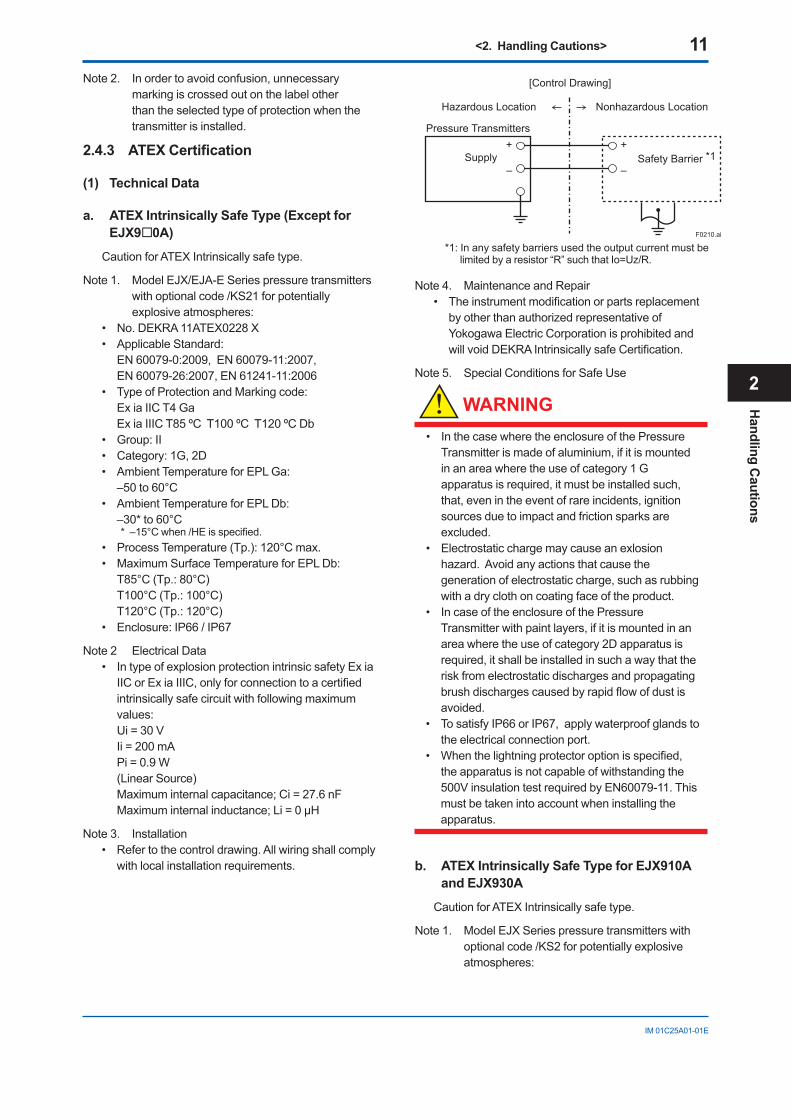
Note3. Installation• Refertothecontroldrawing.Allwiringshallcomply
withlocalinstallationrequirements.
Pressure Transmitters
Supply Safety Barrier *1
Nonhazardous Location
[Control Drawing]
Hazardous Location
+
–
+
–
F0210.ai
*1:Inanysafetybarriersusedtheoutputcurrentmustbelimitedbyaresistor“R”suchthatIo=Uz/R.
Note4. MaintenanceandRepair• Theinstrumentmodificationorpartsreplacement
byotherthanauthorizedrepresentativeofYokogawaElectricCorporationisprohibitedandwillvoidDEKRAIntrinsicallysafeCertification.
Note5. SpecialConditionsforSafeUse
WARNING
• InthecasewheretheenclosureofthePressureTransmitterismadeofaluminium,ifitismountedinanareawheretheuseofcategory1Gapparatusisrequired,itmustbeinstalledsuch,that,evenintheeventofrareincidents,ignitionsourcesduetoimpactandfrictionsparksareexcluded.
• Electrostaticchargemaycauseanexlosionhazard.Avoidanyactionsthatcausethegenerationofelectrostaticcharge,suchasrubbingwithadryclothoncoatingfaceoftheproduct.
• IncaseoftheenclosureofthePressureTransmitterwithpaintlayers,ifitismountedinanareawheretheuseofcategory2Dapparatusisrequired,itshallbeinstalledinsuchawaythattheriskfromelectrostaticdischargesandpropagatingbrushdischargescausedbyrapidflowofdustisavoided.
• TosatisfyIP66orIP67,applywaterproofglandstotheelectricalconnectionport.
• Whenthelightningprotectoroptionisspecified,theapparatusisnotcapableofwithstandingthe500VinsulationtestrequiredbyEN60079-11.Thismustbetakenintoaccountwheninstallingtheapparatus.
b. ATEX Intrinsically Safe Type for EJX910A and EJX930A
CautionforATEXIntrinsicallysafetype.
Note1. ModelEJXSeriespressuretransmitterswithoptionalcode/KS2forpotentiallyexplosiveatmospheres:
Handling C
autions
2
<2. Handling Cautions> 12
IM01C25A01-01E
• No.KEMA06ATEX0037X• ApplicableStandard:
EN50014:1997,EN50020:2002, EN50284:1999,EN50281-1-1:1998
• TypeofProtectionandMarkingcode:EExiaIICT4
• Group:II• Category:1G,1D• AmbientTemperatureforgas-proof:
–50*to60°C *–15°Cwhen/HEisspecified.• ProcessTemperature(Tp.):120°Cmax.• MaximumSurfaceTemperaturefordust-proof:
T85°C(Tamb.:–40*to60°C,Tp.:80°C) T100°C(Tamb.:–40*to60°C,Tp.:100°C) T120°C(Tamb.:–40*to60°C,Tp.:120°C)
*–15°Cwhen/HEisspecified.• Enclosure:IP66andIP67
Note2. ElectricalData[Supply/Outputcircuit(terminals+and-)] IntypeofexplosionprotectionintrinsicsafetyEEx
iaIIC,onlyforconnectiontoacertifiedintrinsicallysafecircuitwithfollowingmaximumvalues: Ui=30V Ii=200mA Pi=0.9W
Effectiveinternalcapacitance;Ci=10nF Effectiveinternalinductance;Li=0mH[PulseOutputcircuit(terminals-andpulse)] IntypeofexplosionprotectionintrinsicsafetyEEx
iaIIC,onlyforconnectiontoacertifiedintrinsicallysafecircuitwithfollowingmaximumvalues: Ui=30V
Ii=200mA Pi=0.9W Ci=10nF Li=0mH[Externaltemperatureinputcircuit(connector)] IntypeofexplosionprotectionintrinsicsafetyEEx
iaIIC,withfollowingmaximumvalues: Uo=30V
Io=95.4mA Po=468mW
Co=11nF Lo=3.9mH
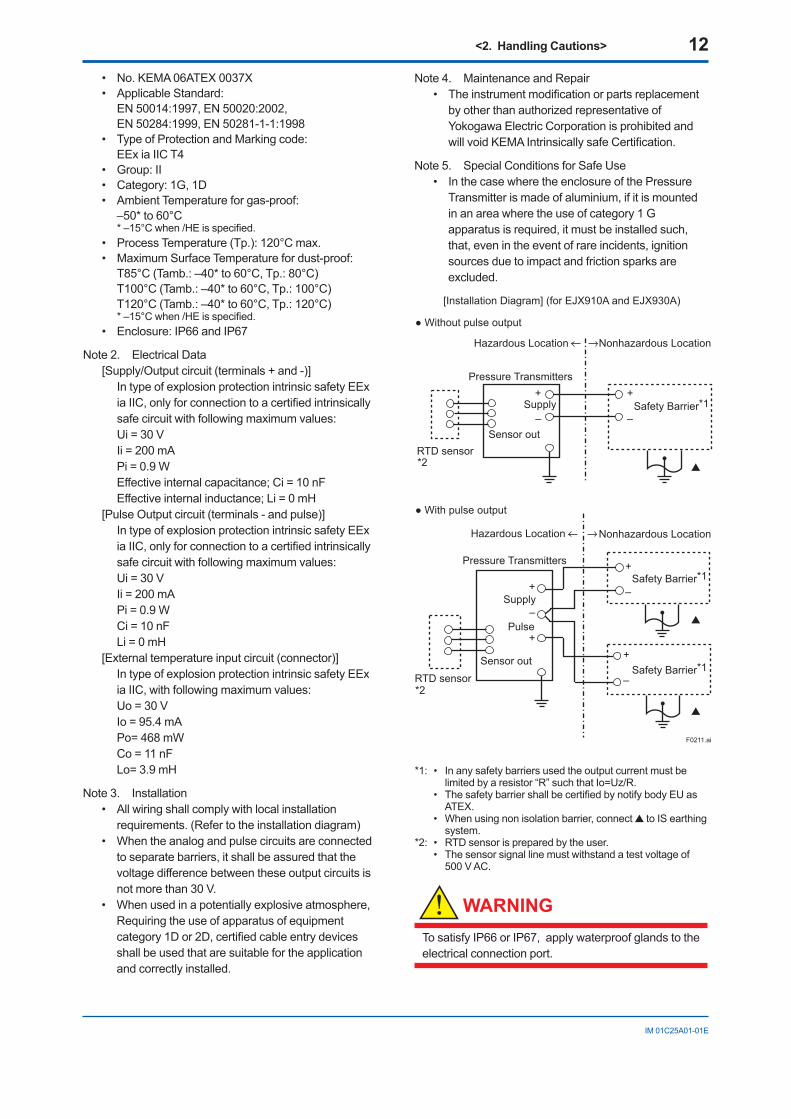
Note3. Installation• Allwiringshallcomplywithlocalinstallation
requirements.(Refertotheinstallationdiagram)• Whentheanalogandpulsecircuitsareconnected
toseparatebarriers,itshallbeassuredthatthevoltagedifferencebetweentheseoutputcircuitsisnotmorethan30V.
• Whenusedinapotentiallyexplosiveatmosphere,Requiringtheuseofapparatusofequipmentcategory1Dor2D,certifiedcableentrydevicesshallbeusedthataresuitablefortheapplicationand correctly installed.
Note4. MaintenanceandRepair• Theinstrumentmodificationorpartsreplacement
byotherthanauthorizedrepresentativeofYokogawaElectricCorporationisprohibitedandwillvoidKEMAIntrinsicallysafeCertification.
Note5. SpecialConditionsforSafeUse• InthecasewheretheenclosureofthePressure
Transmitterismadeofaluminium,ifitismountedinanareawheretheuseofcategory1Gapparatusisrequired,itmustbeinstalledsuch,that,evenintheeventofrareincidents,ignitionsourcesduetoimpactandfrictionsparksareexcluded.
Pressure Transmitters
Supply Safety Barrier*1
Nonhazardous Location
[Installation Diagram] (for EJX910A and EJX930A)
Hazardous Location
+
–
+
–
F0211.ai
Sensor outRTD sensor *2
Without pulse output
With pulse output
Pressure Transmitters
Supply
Safety Barrier*1
Nonhazardous LocationHazardous Location
+
– +
–
+
Sensor outRTD sensor *2
Safety Barrier*1
+
–
Pulse
*1: • Inanysafetybarriersusedtheoutputcurrentmustbelimitedbyaresistor“R”suchthatIo=Uz/R.
• ThesafetybarriershallbecertifiedbynotifybodyEUasATEX.
• Whenusingnonisolationbarrier,connect toISearthingsystem.
*2: • RTDsensorispreparedbytheuser. • Thesensorsignallinemustwithstandatestvoltageof
500VAC.
WARNING
TosatisfyIP66orIP67,applywaterproofglandstotheelectrical connection port.
<2. Handling Cautions> 13
IM01C25A01-01E
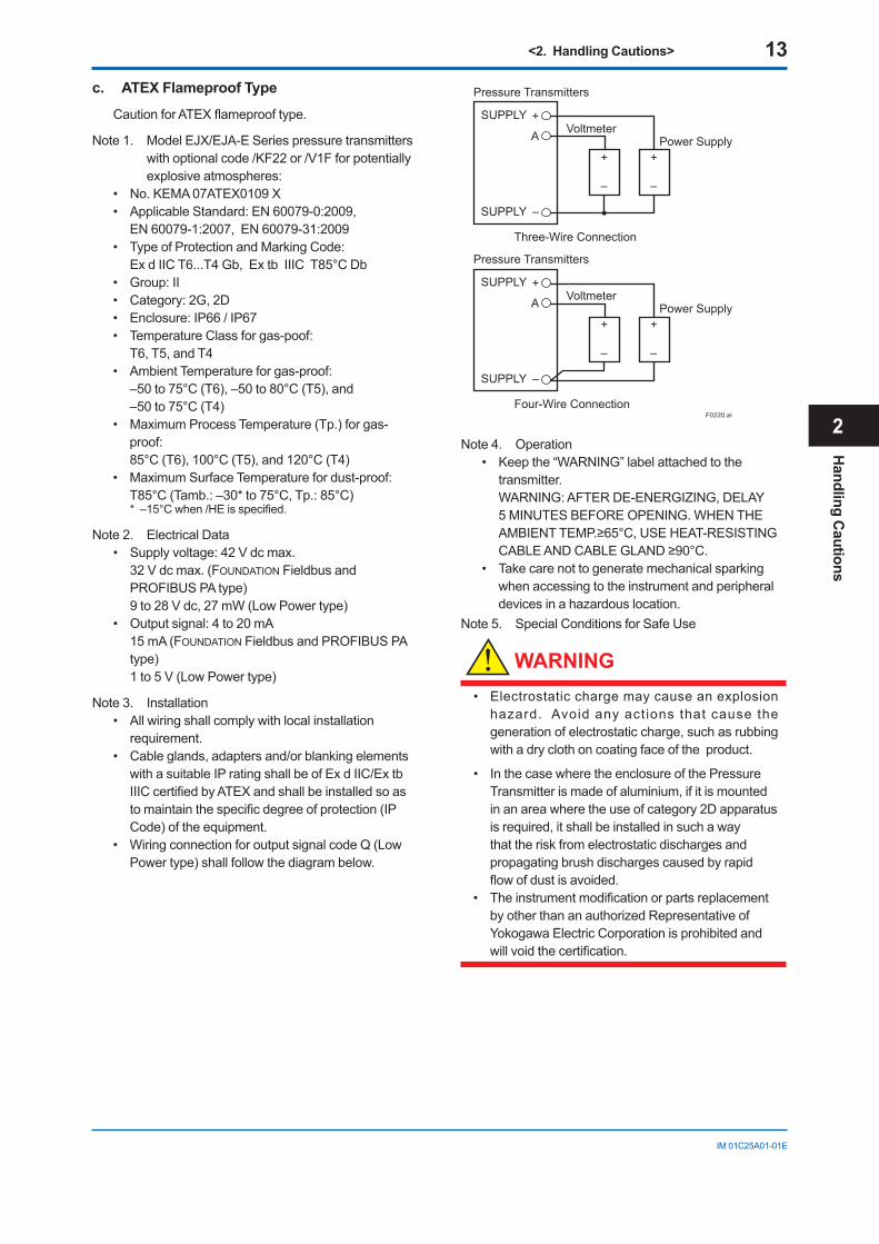
c. ATEX Flameproof Type
CautionforATEXflameprooftype.
Note1. ModelEJX/EJA-ESeriespressuretransmitterswithoptionalcode/KF22or/V1Fforpotentiallyexplosiveatmospheres:
• No.KEMA07ATEX0109X• ApplicableStandard:EN60079-0:2009,
EN60079-1:2007,EN60079-31:2009• TypeofProtectionandMarkingCode: ExdIICT6...T4Gb,ExtbIIICT85°CDb• Group:II• Category:2G,2D• Enclosure:IP66/IP67• TemperatureClassforgas-poof:
T6,T5,andT4• AmbientTemperatureforgas-proof:
–50to75°C(T6),–50to80°C(T5),and –50to75°C(T4)
• MaximumProcessTemperature(Tp.)forgas-proof:
85°C(T6),100°C(T5),and120°C(T4)• MaximumSurfaceTemperaturefordust-proof:
T85°C(Tamb.:–30*to75°C,Tp.:85°C) *–15°Cwhen/HEisspecified.
Note2. ElectricalData• Supplyvoltage:42Vdcmax.
32Vdcmax.(FOUNDATIONFieldbusandPROFIBUSPAtype)9to28Vdc,27mW(LowPowertype)
• Outputsignal:4to20mA15 mA (FOUNDATIONFieldbusandPROFIBUSPAtype)1to5V(LowPowertype)
Note3. Installation• Allwiringshallcomplywithlocalinstallation
requirement.• Cableglands,adaptersand/orblankingelements
withasuitableIPratingshallbeofExdIIC/ExtbIIICcertifiedbyATEXandshallbeinstalledsoastomaintainthespecificdegreeofprotection(IPCode)oftheequipment.
• WiringconnectionforoutputsignalcodeQ(LowPowertype)shallfollowthediagrambelow.
F0220.ai
Three-Wire Connection
Pressure Transmitters
Power SupplyVoltmeter
SUPPLY +
SUPPLY –
A
+
–
+
–
Four-Wire Connection
Pressure Transmitters
Power SupplyVoltmeter
SUPPLY +
SUPPLY –
A
+
–
+
–
Note4. Operation• Keepthe“WARNING”labelattachedtothe
transmitter. WARNING:AFTERDE-ENERGIZING,DELAY
5MINUTESBEFOREOPENING.WHENTHEAMBIENTTEMP.≥65°C,USEHEAT-RESISTINGCABLEANDCABLEGLAND≥90°C.
• Takecarenottogeneratemechanicalsparkingwhenaccessingtotheinstrumentandperipheraldevicesinahazardouslocation.
Note5. SpecialConditionsforSafeUse
WARNING
• Electrostaticchargemaycauseanexplosionhazard.Avoidanyactionsthatcausethegenerationofelectrostaticcharge,suchasrubbingwithadryclothoncoatingfaceoftheproduct.
• InthecasewheretheenclosureofthePressureTransmitterismadeofaluminium,ifitismountedinanareawheretheuseofcategory2Dapparatusisrequired,itshallbeinstalledinsuchawaythattheriskfromelectrostaticdischargesandpropagatingbrushdischargescausedbyrapidflowofdustisavoided.
• TheinstrumentmodificationorpartsreplacementbyotherthananauthorizedRepresentativeofYokogawaElectricCorporationisprohibitedandwillvoidthecertification.
Handling C
autions
2
<2. Handling Cautions> 14
IM01C25A01-01E
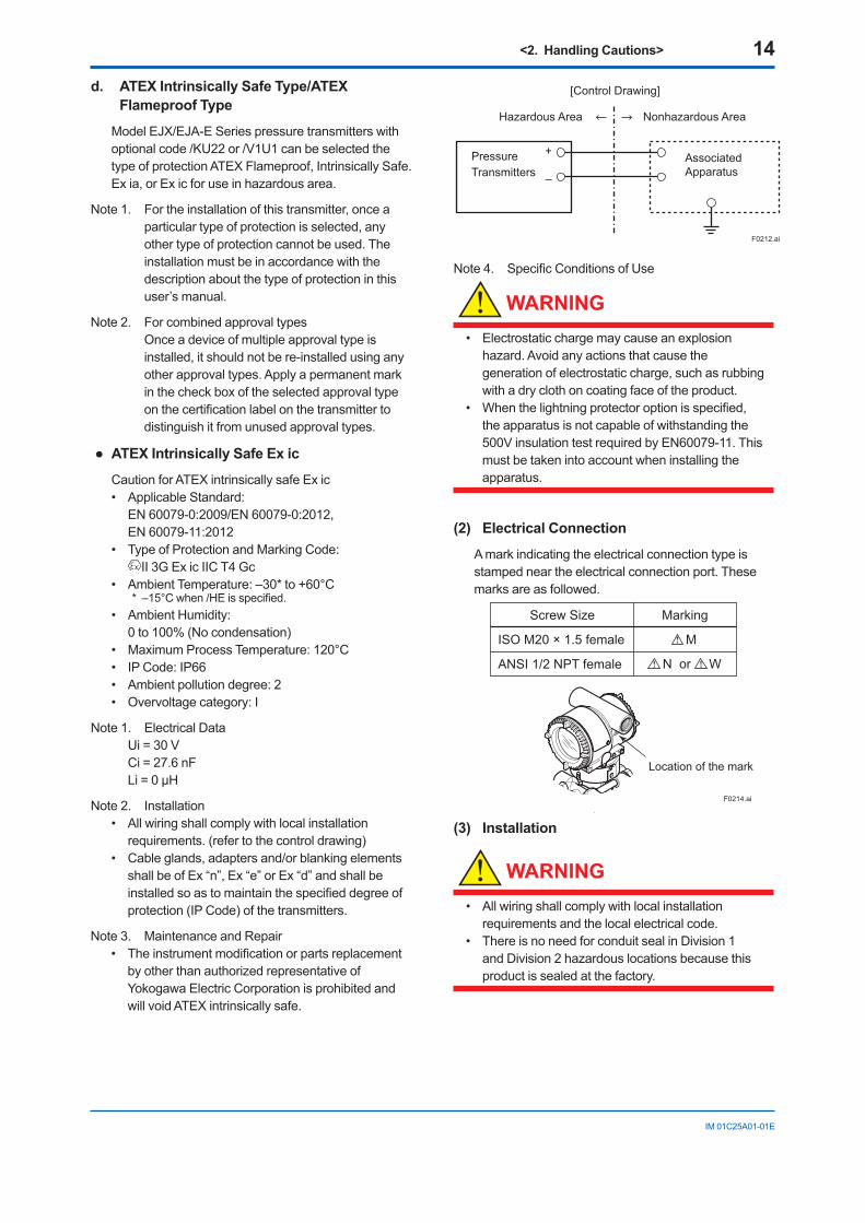
d. ATEX Intrinsically Safe Type/ATEX Flameproof Type
ModelEJX/EJA-ESeriespressuretransmitterswithoptionalcode/KU22or/V1U1canbeselectedthetypeofprotectionATEXFlameproof,IntrinsicallySafe.Exia,orExicforuseinhazardousarea.
Note1. Fortheinstallationofthistransmitter,onceaparticulartypeofprotectionisselected,anyothertypeofprotectioncannotbeused.Theinstallationmustbeinaccordancewiththedescriptionaboutthetypeofprotectioninthisuser’smanual.
Note2. Forcombinedapprovaltypes Once a device of multiple approval type is installed,itshouldnotbere-installedusinganyotherapprovaltypes.Applyapermanentmarkinthecheckboxoftheselectedapprovaltypeonthecertificationlabelonthetransmittertodistinguishitfromunusedapprovaltypes.
ATEXIntrinsicallySafeExic
CautionforATEXintrinsicallysafeExic• ApplicableStandard:
EN60079-0:2009/EN60079-0:2012, EN60079-11:2012
• TypeofProtectionandMarkingCode: II3GExicIICT4Gc
• AmbientTemperature:–30*to+60°C*–15°Cwhen/HEisspecified.
• AmbientHumidity: 0to100%(Nocondensation)
• MaximumProcessTemperature:120°C• IPCode:IP66• Ambientpollutiondegree:2• Overvoltagecategory:I
Note1. ElectricalData Ui=30V Ci=27.6nF Li=0µH
Note2. Installation• Allwiringshallcomplywithlocalinstallation
requirements.(refertothecontroldrawing)• Cableglands,adaptersand/orblankingelements
shallbeofEx“n”,Ex“e”orEx“d”andshallbeinstalledsoastomaintainthespecifieddegreeofprotection(IPCode)ofthetransmitters.
Note3. MaintenanceandRepair• Theinstrumentmodificationorpartsreplacement
byotherthanauthorizedrepresentativeofYokogawaElectricCorporationisprohibitedandwill void ATEX intrinsically safe.
Pressure Transmitters
AssociatedApparatus
Nonhazardous Area
[Control Drawing]
Hazardous Area
+
–
F0212.ai
Note4. SpecificConditionsofUse
WARNING
• Electrostaticchargemaycauseanexplosionhazard.Avoidanyactionsthatcausethegenerationofelectrostaticcharge,suchasrubbingwithadryclothoncoatingfaceoftheproduct.
• Whenthelightningprotectoroptionisspecified,theapparatusisnotcapableofwithstandingthe500VinsulationtestrequiredbyEN60079-11.Thismustbetakenintoaccountwheninstallingtheapparatus.
(2) Electrical Connection
Amarkindicatingtheelectricalconnectiontypeisstampedneartheelectricalconnectionport.Thesemarksareasfollowed.
F0214.ai
Location of the mark
Screw Size Marking
ISO M20 × 1.5 female
ANSI 1/2 NPT female
M
N or W
(3) Installation
WARNING
• Allwiringshallcomplywithlocalinstallationrequirementsandthelocalelectricalcode.
• ThereisnoneedforconduitsealinDivision1andDivision2hazardouslocationsbecausethisproductissealedatthefactory.
<2. Handling Cautions> 15
IM01C25A01-01E
(4) Operation
WARNING
• OPENCIRCUITBEFOREREMOVINGCOVER.INSTALLINACCORDANCEWITHTHISUSER’SMANUAL
• Takecarenottogeneratemechanicalsparkingwhenaccesstotheinstrumentandperipheraldevicesinahazardouslocation.
(5) Maintenance and Repair
WARNING
TheinstrumentmodificationorpartsreplacementbyotherthananauthorizedRepresentativeofYokogawaElectricCorporationisprohibitedandwillvoidthecertification.
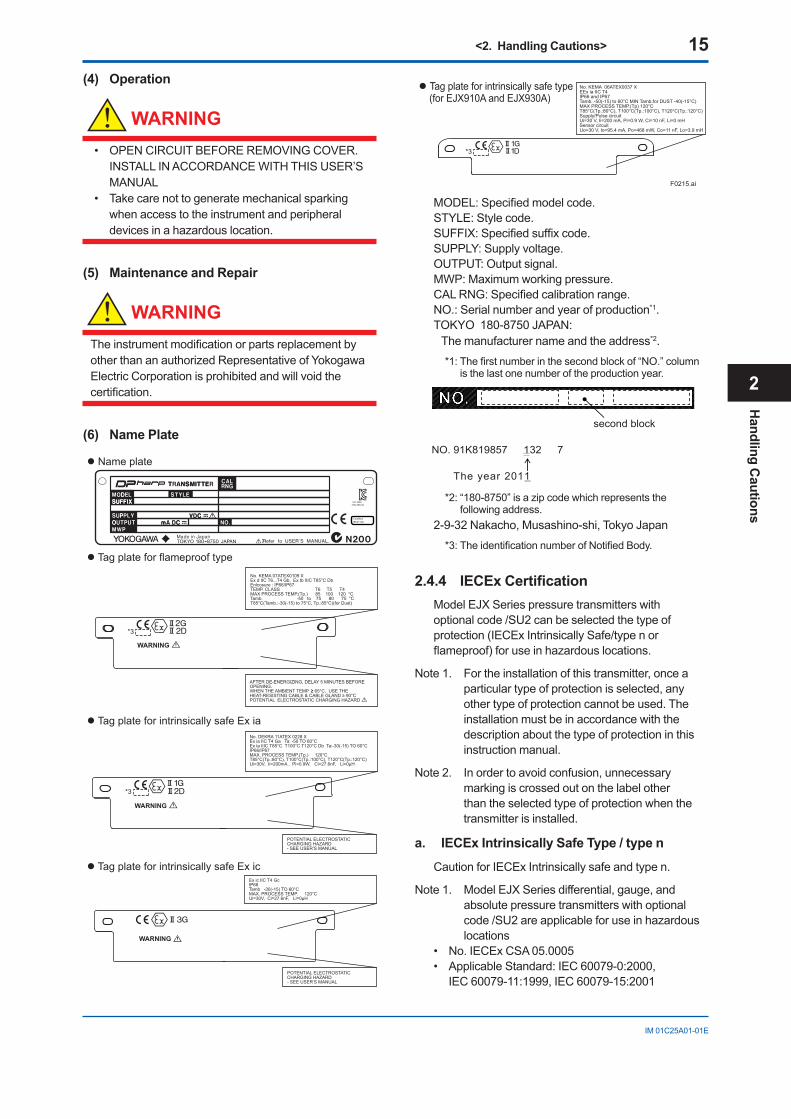
(6) Name Plate
F0215.ai
Name plate
Tag plate for flameproof type
Tag plate for intrinsically safe Ex ia
WARNING
D
DWARNING
No. KEMA 07ATEX0109 XEx d IIC T6...T4 Gb, Ex tb IIIC T85°C DbEnlcosure : IP66/IP67TEMP. CLASS T6 T5 T4MAX PROCESS TEMP.(Tp.) 85 100 120 °CTamb. -50 to 75 80 75 °C T85°C(Tamb.:-30(-15) to 75°C, Tp.:85°C)(for Dust)
No. DEKRA 11ATEX 0228 X Ex ia IIC T4 Ga Ta: -50 TO 60°CEx ia IIIC T85°C T100°C T120°C Db Ta:-30(-15) TO 60°CIP66/IP67MAX. PROCESS TEMP.(Tp.) 120°CT85°C(Tp.:80°C), T100°C(Tp.:100°C), T120°C(Tp.:120°C)Ui=30V, Ii=200mA , Pi=0.9W, Ci=27.6nF, Li=0µH
POTENTIAL ELECTROSTATIC CHARGING HAZARD- SEE USER’S MANUAL
AFTER DE-ENERGIZING, DELAY 5 MINUTES BEFORE OPENING. WHEN THE AMBIENT TEMP. ≥ 65°C, USE THE HEAT-RESISTING CABLE & CABLE GLAND ≥ 90°CPOTENTIAL ELECTROSTATIC CHARGING HAZARD
Tag plate for intrinsically safe type (for EJX910A and EJX930A)
D
No. KEMA 06ATEX0037 XEEx ia IIC T4IP66 and IP67Tamb. -50(-15) to 60°C MIN Tamb.for DUST -40(-15°C)MAX PROCESS TEMP.(Tp) 120°CT85°C(Tp.:80°C), T100°C(Tp.:100°C), T120°C(Tp.:120°C)Supply/Pulse circuit Ui=30 V, Ii=200 mA, Pi=0.9 W, Ci=10 nF, Li=0 mHSensor circuitUo=30 V, Io=95.4 mA, Po=468 mW, Co=11 nF, Lo=3.9 mH
Tag plate for intrinsically safe Ex ic
WARNING
Ex ic IIC T4 GcIP66Tamb -30(-15) TO 60°C MAX. PROCESS TEMP. 120°CUi=30V, Ci=27.6nF, Li=0µH
POTENTIAL ELECTROSTATIC CHARGING HAZARD- SEE USER’S MANUAL
*3
*3
*3
MODEL:Specifiedmodelcode.STYLE:Stylecode.SUFFIX:Specifiedsuffixcode.SUPPLY:Supplyvoltage.OUTPUT:Outputsignal.MWP:Maximumworkingpressure.CALRNG:Specifiedcalibrationrange.NO.:Serialnumberandyearofproduction*1.TOKYO180-8750JAPAN:Themanufacturernameandtheaddress*2.
*1:Thefirstnumberinthesecondblockof“NO.”columnisthelastonenumberoftheproductionyear.
second block
NO. 91K819857 132 7
The year 2011
*2:“180-8750”isazipcodewhichrepresentsthe following address.
2-9-32Nakacho,Musashino-shi,TokyoJapan
*3:TheidentificationnumberofNotifiedBody.
2.4.4 IECExCertificationModelEJXSeriespressuretransmitterswithoptionalcode/SU2canbeselectedthetypeofprotection(IECExIntrinsicallySafe/typenorflameproof)foruseinhazardouslocations.
Note1. Fortheinstallationofthistransmitter,onceaparticulartypeofprotectionisselected,anyothertypeofprotectioncannotbeused.Theinstallationmustbeinaccordancewiththedescriptionaboutthetypeofprotectioninthisinstruction manual.
Note2. Inordertoavoidconfusion,unnecessarymarkingiscrossedoutonthelabelotherthantheselectedtypeofprotectionwhenthetransmitter is installed.
a. IECEx Intrinsically Safe Type / type n
CautionforIECExIntrinsicallysafeandtypen.
Note1. ModelEJXSeriesdifferential,gauge,andabsolutepressuretransmitterswithoptionalcode/SU2areapplicableforuseinhazardouslocations
• No.IECExCSA05.0005• ApplicableStandard:IEC60079-0:2000,
IEC60079-11:1999,IEC60079-15:2001
Handling C
autions
2
<2.HandlingCautions> 16
IM 01C25A01-01E
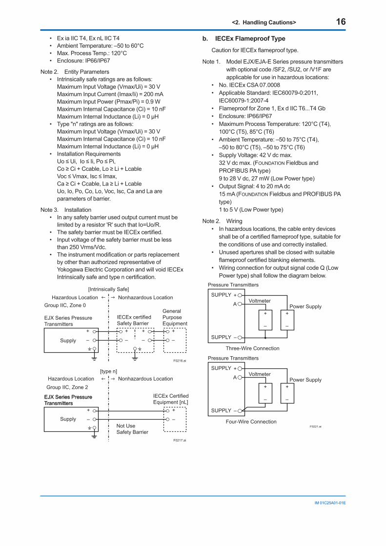
• Ex ia IIC T4, Ex nL IIC T4 • Ambient Temperature: –50 to 60°C • Max. Process Temp.: 120°C• Enclosure: IP66/IP67
Note 2. Entity Parameters• Intrinsically safe ratings are as follows:
Maximum Input Voltage (Vmax/Ui) = 30 V Maximum Input Current (Imax/Ii) = 200 mA Maximum Input Power (Pmax/Pi) = 0.9 W Maximum Internal Capacitance (Ci) = 10 nF Maximum Internal Inductance (Li) = 0 µH
• Type "n" ratings are as follows:Maximum Input Voltage (Vmax/Ui) = 30 V Maximum Internal Capacitance (Ci) = 10 nF Maximum Internal Inductance (Li) = 0 µH
• Installation RequirementsUo ≤ Ui, Io ≤ Ii, Po ≤ Pi, Co ≥ Ci + Ccable, Lo ≥ Li + Lcable Voc ≤ Vmax, Isc ≤ Imax, Ca ≥ Ci + Ccable, La ≥ Li + Lcable Uo, Io, Po, Co, Lo, Voc, Isc, Ca and La are parameters of barrier.
Note 3. Installation• In any safety barrier used output current must be
limited by a resistor 'R' such that Io=Uo/R.• The safety barrier must be IECEx certified.• Input voltage of the safety barrier must be less
than 250 Vrms/Vdc.• The instrument modification or parts replacement
by other than authorized representative of Yokogawa Electric Corporation and will void IECEx Intrinsically safe and type n certification.
F0216.ai
EJX Series Pressure Transmitters
IECEx certifiedSafety Barrier
Supply
Hazardous Location Nonhazardous Location
General PurposeEquipment
+
–
+
–
+
–
+
–
[Intrinsically Safe]
Group IIC, Zone 0
F0217.ai
EJX Series Pressure Transmitters
Supply
Hazardous Location Nonhazardous Location
+
–
+
– Not UseSafety Barrier
[type n]
IECEx Certified Equipment [nL]
EJX Series Pressure Transmitters
Group IIC, Zone 2
b. IECExFlameproofType
Caution for IECEx flameproof type.
Note 1. Model EJX/EJA-E Series pressure transmitters with optional code /SF2, /SU2, or /V1F are applicable for use in hazardous locations:
• No. IECEx CSA 07.0008• Applicable Standard: IEC60079-0:2011,
IEC60079-1:2007-4• Flameproof for Zone 1, Ex d IIC T6...T4 Gb• Enclosure: IP66/IP67• Maximum Process Temperature: 120°C (T4),
100°C (T5), 85°C (T6)• Ambient Temperature: –50 to 75°C (T4),
–50 to 80°C (T5), –50 to 75°C (T6)• Supply Voltage: 42 V dc max.
32 V dc max. (FOUNDATION Fieldbus and PROFIBUS PA type)9 to 28 V dc, 27 mW (Low Power type)
• Output Signal: 4 to 20 mA dc15 mA (FOUNDATION Fieldbus and PROFIBUS PA type)1 to 5 V (Low Power type)
Note 2. Wiring• In hazardous locations, the cable entry devices
shall be of a certified flameproof type, suitable for the conditions of use and correctly installed.
• Unused apertures shall be closed with suitable flameproof certified blanking elements.
• Wiring connection for output signal code Q (Low Power type) shall follow the diagram below.
F0221.ai
Three-Wire Connection
Pressure Transmitters
Power SupplyVoltmeter
SUPPLY +
SUPPLY –
A
+
–
+
–
Four-Wire Connection
Pressure Transmitters
Power SupplyVoltmeter
SUPPLY +
SUPPLY –
A
+
–
+
–
<2.HandlingCautions> 17
IM 01C25A01-01E
Note 3. Operation• WARNING:
AFTER DE-ENERGIZING, DELAY 5 MINUTES BEFORE OPENING.
• WARNING: WHEN THE AMBIENT TEMP.≥65°C, USE HEAT-
RESISTING CABLE AND CABLE GLAND ≥90°C.• Take care not to generate mechanical sparking
when accessing to the instrument and peripheral devices in a hazardous location.
• Electrostatic charge may cause an explosion hazard. Avoid any actions that cause the generation of electrostatic charge, such as rubbing with a dry cloth on coating face of the product.
Note 4. Maintenance and Repair• The instrument modification or parts replacement
by other than authorized representative of Yokogawa Electric Corporation is prohibited and will void IECEx Certification.
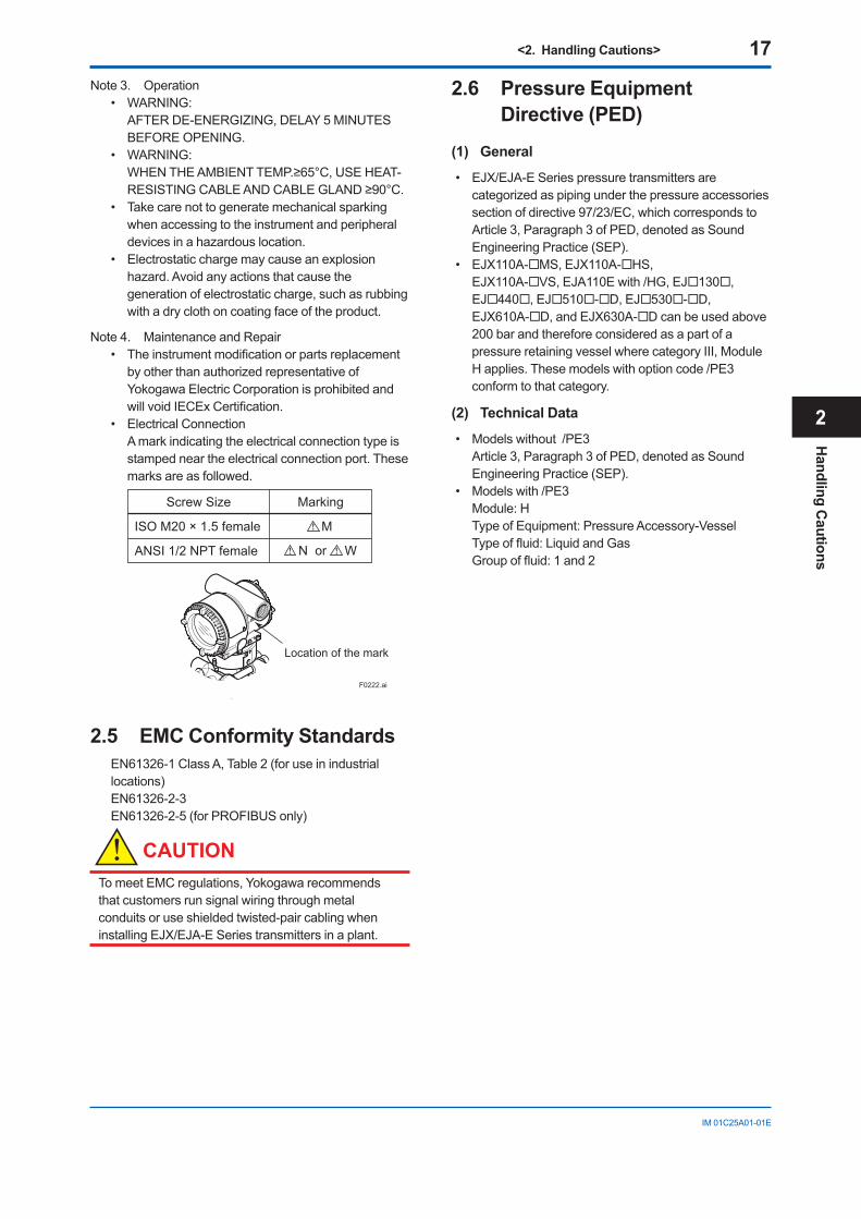
• Electrical ConnectionA mark indicating the electrical connection type is stamped near the electrical connection port. These marks are as followed.
F0222.ai
Location of the mark
Screw Size Marking
ISO M20 × 1.5 female
ANSI 1/2 NPT female
M
N or W
2.5 EMCConformityStandardsEN61326-1 Class A, Table 2 (for use in industrial locations) EN61326-2-3EN61326-2-5 (for PROFIBUS only)
CAUTIONTo meet EMC regulations, Yokogawa recommends that customers run signal wiring through metal conduits or use shielded twisted-pair cabling when installing EJX/EJA-E Series transmitters in a plant.
2.6 PressureEquipmentDirective(PED)
(1) General
• EJX/EJA-E Series pressure transmitters are categorized as piping under the pressure accessories section of directive 97/23/EC, which corresponds to Article 3, Paragraph 3 of PED, denoted as Sound Engineering Practice (SEP).
• EJX110A-MS, EJX110A-HS, EJX110A-VS, EJA110E with /HG, EJ130, EJ440, EJ510-D, EJ530-D, EJX610A-D, and EJX630A-D can be used above 200 bar and therefore considered as a part of a pressure retaining vessel where category III, Module H applies. These models with option code /PE3 conform to that category.
(2) TechnicalData
• Models without /PE3 Article 3, Paragraph 3 of PED, denoted as Sound Engineering Practice (SEP).
• Models with /PE3 Module: H Type of Equipment: Pressure Accessory-Vessel Type of fluid: Liquid and Gas Group of fluid: 1 and 2
HandlingC
autions
2
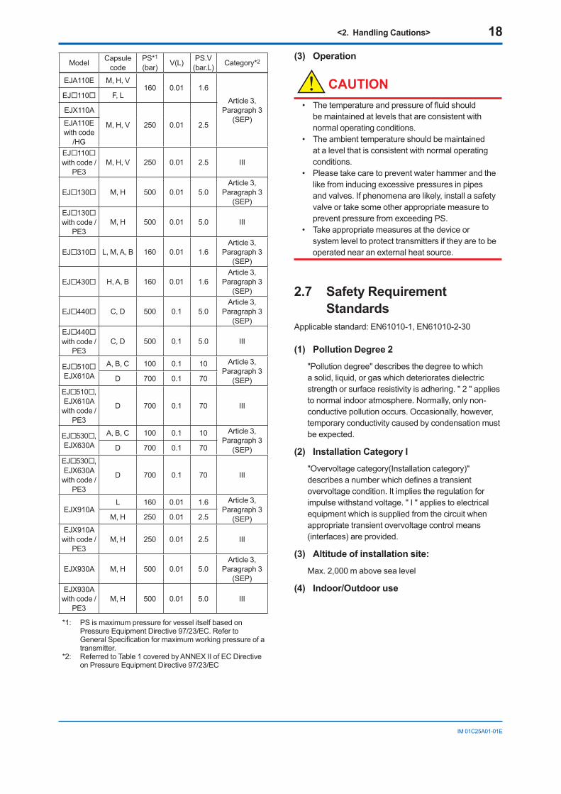
<2. Handling Cautions> 18
IM01C25A01-01E
Model Capsulecode
PS*1
(bar) V(L) PS.V(bar.L) Category*2
EJA110E M,H,V160 0.01 1.6
Article3,Paragraph3
(SEP)
EJ110 F,L
EJX110A
M,H,V 250 0.01 2.5EJA110Ewithcode
/HGEJ110withcode/
PE3M,H,V 250 0.01 2.5 III
EJ130 M,H 500 0.01 5.0Article3,
Paragraph3(SEP)
EJ130withcode/
PE3M,H 500 0.01 5.0 III
EJ310 L,M,A,B 160 0.01 1.6Article3,
Paragraph3(SEP)
EJ430 H,A,B 160 0.01 1.6Article3,
Paragraph3(SEP)
EJ440 C,D 500 0.1 5.0Article3,
Paragraph3(SEP)
EJ440withcode/
PE3C,D 500 0.1 5.0 III
EJ510EJX610A
A,B,C 100 0.1 10 Article3,Paragraph3
(SEP)D 700 0.1 70
EJ510,EJX610Awithcode/
PE3
D 700 0.1 70 III
EJ530,EJX630A
A,B,C 100 0.1 10 Article3,Paragraph3
(SEP)D 700 0.1 70
EJ530,EJX630Awithcode/
PE3
D 700 0.1 70 III
EJX910AL 160 0.01 1.6 Article3,
Paragraph3(SEP)M,H 250 0.01 2.5
EJX910Awithcode/
PE3M,H 250 0.01 2.5 III
EJX930A M,H 500 0.01 5.0Article3,
Paragraph3(SEP)
EJX930Awithcode/
PE3M,H 500 0.01 5.0 III
*1: PSismaximumpressureforvesselitselfbasedonPressureEquipmentDirective97/23/EC.RefertoGeneralSpecificationformaximumworkingpressureofatransmitter.
*2: ReferredtoTable1coveredbyANNEXIIofECDirectiveonPressureEquipmentDirective97/23/EC
(3) Operation
CAUTION• Thetemperatureandpressureoffluidshould
bemaintainedatlevelsthatareconsistentwithnormal operating conditions.
• Theambienttemperatureshouldbemaintainedatalevelthatisconsistentwithnormaloperatingconditions.
• Pleasetakecaretopreventwaterhammerandthelikefrominducingexcessivepressuresinpipesandvalves.Ifphenomenaarelikely,installasafetyvalveortakesomeotherappropriatemeasuretopreventpressurefromexceedingPS.
• Takeappropriatemeasuresatthedeviceorsystemleveltoprotecttransmittersiftheyaretobeoperatednearanexternalheatsource.
2.7 Safety Requirement Standards
Applicablestandard:EN61010-1,EN61010-2-30
(1) Pollution Degree 2
"Pollutiondegree"describesthedegreetowhichasolid,liquid,orgaswhichdeterioratesdielectricstrengthorsurfaceresistivityisadhering."2"appliestonormalindooratmosphere.Normally,onlynon-conductivepollutionoccurs.Occasionally,however,temporaryconductivitycausedbycondensationmustbeexpected.
(2) Installation Category I
"Overvoltagecategory(Installationcategory)"describesanumberwhichdefinesatransientovervoltagecondition.Itimpliestheregulationforimpulsewithstandvoltage."I"appliestoelectricalequipmentwhichissuppliedfromthecircuitwhenappropriate transient overvoltage control means (interfaces) are provided.
(3) Altitude of installation site:
Max.2,000mabovesealevel
(4) Indoor/Outdoor use
<3. Installation> 19
IM01C25A01-01E
3. InstallationIMPORTANT
• Whenweldingpipingduringconstruction,takecarenottoallowweldingcurrentstoflowthroughthetransmitter.
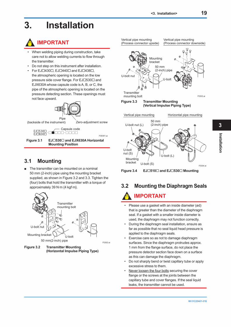
• Donotsteponthisinstrumentafterinstallation.• ForEJ430,EJ440andEJ438,
theatmosphericopeningislocatedonthelowpressuresidecoverflange.ForEJ530 and EJX630AwhosecapsulecodeisA,B,orC,thepipeoftheatmosphericopeningislocatedonthepressuredetectingsection.Theseopeningsmustnot face upward.
F00301.ai
Capsule code
Zero-adjustment screwPipe
(backside of the instrument)
6
Figure 3.1 EJ530 and EJX630A Horizontal Mounting Position
3.1 Mounting Thetransmittercanbemountedonanominal
50mm(2-inch)pipeusingthemountingbracketsupplied,asshowninFigure3.2and3.3.Tightenthe(four)boltsthatholdthetransmitterwithatorqueofapproximately39N·m4kgf·m.
Transmittermounting bolt
U-bolt nut
Mounting bracket
50 mm(2-inch) pipeU-bolt
F0302.ai
Figure 3.2 Transmitter Mounting (Horizontal Impulse Piping Type)
Vertical pipe mounting(Process connector upside)
Transmittermounting bolt
Mounting bracket
U-bolt nutU-bolt
50 mm(2-inch) pipe
Vertical pipe mounting(Process connector downside)
F0303.ai
Figure 3.3 Transmitter Mounting (Vertical Impulse Piping Type)
Vertical pipe mounting
50 mm (2-inch) pipe
U-bolt (L)
U-bolt (S)Mounting bracket
U-bolt nut (S)
U-bolt nut (L)
Horizontal pipe mounting
F0304.ai
Figure 3.4 EJ510 and EJ530 Mounting
3.2 Mounting the Diaphragm Seals
IMPORTANT• Pleaseuseagasketwithaninsidediameter(ød)
thatisgreaterthanthediameterofthediaphragmseal.Ifagasketwithasmallerinsidediameterisused,thediaphragmmaynotfunctioncorrectly.
• Duringthediaphragmsealinstallation,ensureasfaraspossiblethatnosealliquidheadpressureisappliedtothediaphragmseals.
• Exercisecaresoasnottodamagediaphragmsurfaces.Sincethediaphragmprotrudesapprox.1mmfromtheflangesurface,donotplacethepressure detector section face down on a surface asthiscandamagethediaphragm.
• Donotsharplybendortwistcapillarytubeorapplyexcessivestresstothem.
• Neverloosenthefourboltssecuringthecoverflangeorthescrewsatthejointsbetweenthecapillarytubeandcoverflanges.Ifthesealliquidleaks,thetransmittercannotbeused.
Installation
3
<3. Installation> 20
IM01C25A01-01E
3.2.1 EJ210ThetransmitterismountedonaprocessusingitshighpressuresideflangeasshowninFigure3.5.Thecustomershouldpreparethematingflange,gasket,studboltsandnuts.
F0305.ai
Gasket
Stud bolt
Nut
Figure 3.5 EJ210 Mounting
3.2.2 EJ118 and EJ438MountthediaphragmsealsusingtheflangesasshowninFigure3.6.Thematingflange,gasket,boltsandnutsaretobeprocuredbythecustomer.
NutFlangeDiaphragm
ødGasket
F0306.ai
Bolt
The product is shipped with these parts assembled.
Correctly install the diaphragm seals on the high and low pressure sides of the process (The label on each diaphragm seal is marked HIGH or LOW).
Figure 3.6 Mounting the Diaphragm Seals
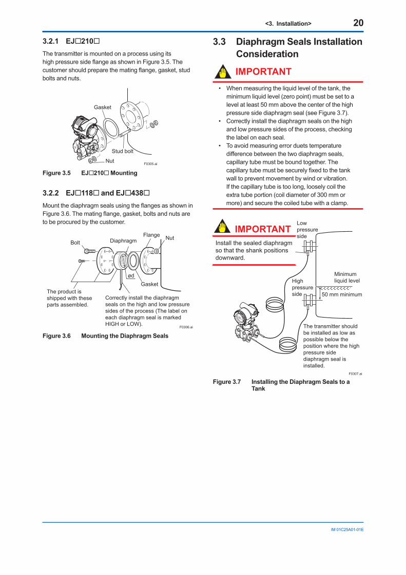
3.3 Diaphragm Seals Installation Consideration
IMPORTANT• Whenmeasuringtheliquidlevelofthetank,the
minimumliquidlevel(zeropoint)mustbesettoalevelatleast50mmabovethecenterofthehighpressuresidediaphragmseal(seeFigure3.7).
• Correctlyinstallthediaphragmsealsonthehighandlowpressuresidesoftheprocess,checkingthelabeloneachseal.
• Toavoidmeasuringerrorduetstemperaturedifferencebetweenthetwodiaphragmseals,capillarytubemustbeboundtogether.Thecapillarytubemustbesecurelyfixedtothetankwalltopreventmovementbywindorvibration. Ifthecapillarytubeistoolong,looselycoiltheextratubeportion(coildiameterof300mmormore)andsecurethecoiledtubewithaclamp.
F0307.ai
50 mm minimum
Minimum liquid levelHigh
pressureside
Low pressure side
The transmitter should be installed as low as possible below the position where the high pressure side diaphragm seal is installed.
Install the sealed diaphragm so that the shank positions downward.
IMPORTANT
Figure 3.7 Installing the Diaphragm Seals to a Tank
<3. Installation> 21
IM01C25A01-01E
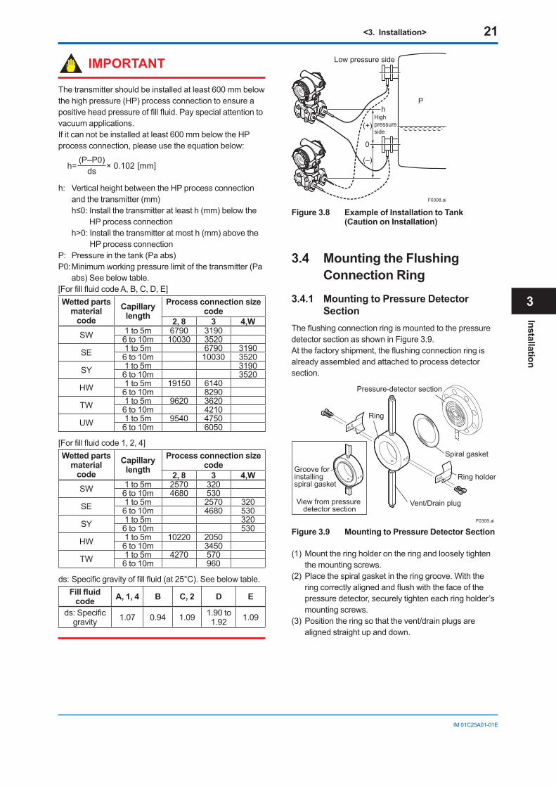
IMPORTANT
Thetransmittershouldbeinstalledatleast600mmbelowthehighpressure(HP)processconnectiontoensureapositiveheadpressureoffillfluid.Payspecialattentiontovacuum applications.Ifitcannotbeinstalledatleast600mmbelowtheHPprocessconnection,pleaseusetheequationbelow:
h= × 0.102 [mm](P–P0)
ds
h: VerticalheightbetweentheHPprocessconnectionandthetransmitter(mm)h≤0:Installthetransmitteratleasth(mm)belowthe
HPprocessconnectionh>0:Installthetransmitteratmosth(mm)abovethe
HPprocessconnectionP: Pressureinthetank(Paabs)P0:Minimumworkingpressurelimitofthetransmitter(Pa
abs)Seebelowtable.[ForfillfluidcodeA,B,C,D,E]Wetted parts
material code
Capillary length
Process connection size code
2, 8 3 4,WSW 1 to 5m 6790 3190
6 to 10m 10030 3520SE 1 to 5m 6790 3190
6 to 10m 10030 3520SY 1 to 5m 3190
6 to 10m 3520HW 1 to 5m 19150 6140
6 to 10m 8290TW 1 to 5m 9620 3620
6 to 10m 4210UW 1 to 5m 9540 4750
6 to 10m 6050
[Forfillfluidcode1,2,4]Wetted parts
material code
Capillary length
Process connection size code
2, 8 3 4,WSW 1 to 5m 2570 320
6 to 10m 4680 530SE 1 to 5m 2570 320
6 to 10m 4680 530SY 1 to 5m 320
6 to 10m 530HW 1 to 5m 10220 2050
6 to 10m 3450TW 1 to 5m 4270 570
6 to 10m 960
ds:Specificgravityoffillfluid(at25°C).Seebelowtable.Fillfluid
code A, 1, 4 B C, 2 D E
ds:Specificgravity 1.07 0.94 1.09 1.90 to
1.92 1.09
F0308.ai
P
Low pressure side
Highpressureside
(+)
(–)
0
h
Figure 3.8 Example of Installation to Tank (Caution on Installation)
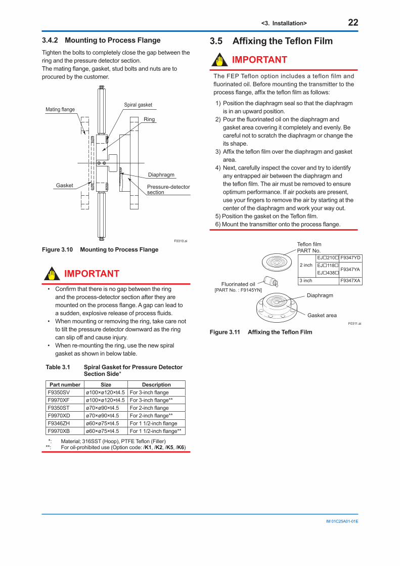
3.4 Mounting the Flushing Connection Ring
3.4.1 Mounting to Pressure Detector Section
TheflushingconnectionringismountedtothepressuredetectorsectionasshowninFigure3.9. Atthefactoryshipment,theflushingconnectionringisalreadyassembledandattachedtoprocessdetectorsection.
Ring holder
Spiral gasket
F0309.ai
View from pressure detector section
Groove for installingspiral gasket
Pressure-detector section
Vent/Drain plug
Ring
Figure 3.9 Mounting to Pressure Detector Section
(1)Mounttheringholderontheringandlooselytightenthemountingscrews.
(2)Placethespiralgasketintheringgroove.Withtheringcorrectlyalignedandflushwiththefaceofthepressuredetector,securelytighteneachringholder’smounting screws.
(3)Positiontheringsothatthevent/drainplugsarealignedstraightupanddown.
Installation
3
<3. Installation> 22
IM01C25A01-01E
3.4.2 Mounting to Process FlangeTightentheboltstocompletelyclosethegapbetweentheringandthepressuredetectorsection.Thematingflange,gasket,studboltsandnutsaretoprocuredbythecustomer.
F0310.ai
Ring
Diaphragm
Pressure-detector section
Gasket
Mating flangeSpiral gasket
Figure 3.10 Mounting to Process Flange
IMPORTANT• Confirmthatthereisnogapbetweenthering
andtheprocess-detectorsectionaftertheyaremountedontheprocessflange.Agapcanleadtoasudden,explosivereleaseofprocessfluids.
• Whenmountingorremovingthering,takecarenottotiltthepressuredetectordownwardastheringcan slip off and cause injury.
• Whenre-mountingthering,usethenewspiralgasketasshowninbelowtable.
Table 3.1 Spiral Gasket for Pressure Detector Section Side*
Part number Size DescriptionF9350SV ø100×ø120×t4.5 For3-inchflangeF9970XF ø100×ø120×t4.5 For3-inchflange**F9350ST ø70×ø90×t4.5 For2-inchflangeF9970XD ø70×ø90×t4.5 For2-inchflange**F9346ZH ø60×ø75×t4.5 For11/2-inchflangeF9970XB ø60×ø75×t4.5 For11/2-inchflange**
*: Material;316SST(Hoop),PTFETeflon(Filler)**: Foroil-prohibiteduse(Optioncode:/K1,/K2,/K5,/K6)
3.5 AffixingtheTeflonFilm
IMPORTANTTheFEPTeflonoptionincludesateflonfilmandfluorinatedoil.Beforemountingthetransmittertotheprocessflange,affixtheteflonfilmasfollows:
1)Positionthediaphragmsealsothatthediaphragmis in an upward position.
2)Pourthefluorinatedoilonthediaphragmandgasketareacoveringitcompletelyandevenly.Becarefulnottoscratchthediaphragmorchangetheitsshape.
3)Affixtheteflonfilmoverthediaphragmandgasketarea.
4)Next,carefullyinspectthecoverandtrytoidentifyanyentrappedairbetweenthediaphragmandtheteflonfilm.Theairmustberemovedtoensureoptimumperformance.Ifairpocketsarepresent,useyourfingerstoremovetheairbystartingatthecenterofthediaphragmandworkyourwayout.
5)PositionthegasketontheTeflonfilm.6)Mountthetransmitterontotheprocessflange.
F0311.ai
EJ210 F9347YDEJ118EJ438
F9347YA2 inch
F9347XA3 inch
Teflon filmPART No.
Diaphragm
Fluorinated oil[PART No. : F9145YN]
Gasket area
Figure3.11 AffixingtheTeflonFilm
<3. Installation> 23
IM01C25A01-01E
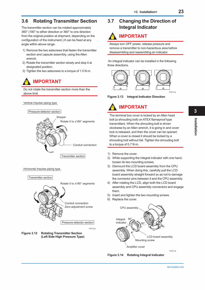
3.6 Rotating Transmitter SectionThetransmittersectioncanberotatedapproximately360°(180°toeitherdirectionor360°toonedirectionfromtheoriginalpositionatshipment,dependingontheconfigurationoftheinstrument.)Itcanbefixedatanyanglewithinaboverange.
1)Removethetwosetscrewsthatfastenthetransmittersectionandcapsuleassembly,usingtheAllenwrench.
2)Rotatethetransmittersectionslowlyandstopitatdesignated position.
3)Tightenthetwosetscrewstoatorqueof1.5N·m.
IMPORTANTDonotrotatethetransmittersectionmorethantheabovelimit.
F0312.ai
Vertical impulse piping type
Horizontal impulse piping type
Pressure-detector section
Transmitter section
Rotate 0 to ±180° segments
Rotate 0 to ±180° segments
Transmitter section
Pressure-detector section
Conduit connection
Conduit connectionZero-adjustment screw
Stopper
Figure 3.12 Rotating Transmitter Section (Left Side High Pressure Type)
3.7 Changing the Direction of Integral Indicator
IMPORTANTAlwaysturnOFFpower,releasepressureandremoveatransmittertonon-hazardousareabeforedisassemblingandreassmblinganindicator.
Anintegralindicatorcanbeinstalledinthefollowingthreedirections.
F0313.ai
Figure 3.13 Integral Indicator Direction
IMPORTANTTheterminalboxcoverislockedbyanAllenheadbolt(ashroudingbolt)onATEXflameprooftypetransmitters.WhentheshroudingboltisdrivenclockwisebyanAllenwrench,itisgoinginandcoverlockisreleased,andthenthecovercanbeopened. Whenacoveriscloseditshouldbelockedbyashroudingboltwithoutfail.Tightentheshroudingbolttoatorqueof0.7N·m.
1) Removethecover.2) Whilesupportingtheintegralindicatorwithonehand,
loosen its two mounting screws.3) DismounttheLCDboardassemblyfromtheCPU
assembly.Whendoingthis,carefullypulltheLCDboardassemblystraightforwardsoasnottodamagetheconnectorpinsbetweenitandtheCPUassembly.
4) AfterrotatingtheLCD,alignboththeLCDboardassemblyandCPUassemblyconnectorsandengagethem.
5) Insertandtightenthetwomountingscrews.6) Replacethecover.
90°90°Integral
indicator
Mounting screw
Amplifier cover
LCD board assembly
CPU assembly
F0314.ai
Figure 3.14 Rotating Integral Indicator
Installation
3
<4. Installing Impulse Piping> 24
IM01C25A01-01E
4. Installing Impulse Piping4.1 Impulse Piping Installation
PrecautionsTheimpulsepipingthatconnectstheprocessoutputstothetransmittermustconveytheprocesspressureaccurately.If,forexample,gascollectsinaliquid-filledimpulseline,orthedrainofagas-filledimpulselinebecomesplugged,itwillnotconveythepressureaccurately.Sincethiswillcauseerrorsinthemeasurementoutput,selecttheproperpipingmethodfortheprocessfluid(gas,liquid,orsteam).Paycarefulattentiontothefollowingpointswhenroutingtheimpulsepipingandconnectingtheimpulsepipingtoatransmitter.
4.1.1 Connecting Impulse Piping to the Transmitter
(1) Check the High and Low Pressure Connections on the Transmitter (Figure 4.1)
Symbols“H”and“L”havebeenplacedonthecapsuleassemblytoindicatehighandlowpressureside.Withdifferentialpressuretransmitters,connectthehighpressuresideimpulselinetothe“H”side,andthelowpressuresideimpulselinetothe“L”side.
Withgauge/absolutepressuretransmitters,connecttheimpulselinetothe‘H’side.
F0401.ai
Process connection
“H” and “L” are shown
Process connection
Process connector
Bolt
Differential Pressure Transmitter
Figure 4.1 “H” and “L” Symbols on a Capsule Assembly
(2) Changing the Process Connector Piping Connections (for differential pressure transmitters)
Theimpulsepipingconnectiondistancescanbechangedbetween51mm,54mmand57mmbychangingtheorientationoftheprocessconnectors.Thisisconvenientforaligningtheimpulselinewithaprocess connectors.
57 mm 54 mm 51 mmF0402.ai
Figure 4.2 Process Connector Impulse Piping Connection Distances
(3) Tightening the Process Connector Mounting Bolts
Afterconnectinganimpulseline,tightentheprocessconnectormountingboltsuniformly.
(4) Removing the Impulse Piping Connecting Port Dustproof Cap
Theimpulsepipingconnectingportonthetransmitteriscoveredwithaplasticcaptokeepoutdust.Thiscapmustberemovedbeforeconnectingtheline.(Becarefulnottodamagethethreadswhenremovingthiscap.Neverinsertascrewdriverorothertoolbetweenthecapandportthreadstoremovethecap.)
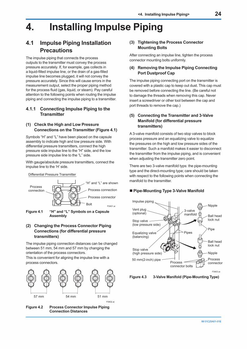
(5) Connecting the Transmitter and 3-Valve Manifold (for differential pressure transmitters)
A3-valvemanifoldconsistsoftwostopvalvestoblockprocesspressureandanequalizingvalvetoequalizethepressuresonthehighandlowpressuresidesofthetransmitter.Suchamanifoldmakesiteasiertodisconnectthetransmitterfromtheimpulsepiping,andisconvenientwhenadjustingthetransmitterzeropoint.
Therearetwo3-valvemanifoldtyps:thepipe-mountingtypeandthedirect-mountingtype;careshouldbetakenwithrespecttothefollowingpointswhenconnectingthemanifoldtothetransmitter.
Pipe-Mounting Type 3-Valve Manifold
F0403.ai
Nipple
Nipple
Processconnector
Ball headlock nut
Pipe
Ball headlock nut
Process connector bolts
50 mm(2-inch) pipe
Pipes
3-valvemanifold
Impulse piping
Vent plug(optional)
Stop valve(low pressure side)
Equalizing valve(balancing)
Stop valve(high pressure side)
Figure 4.3 3-Valve Manifold (Pipe-Mounting Type)
<4. Installing Impulse Piping> 25
IM01C25A01-01E
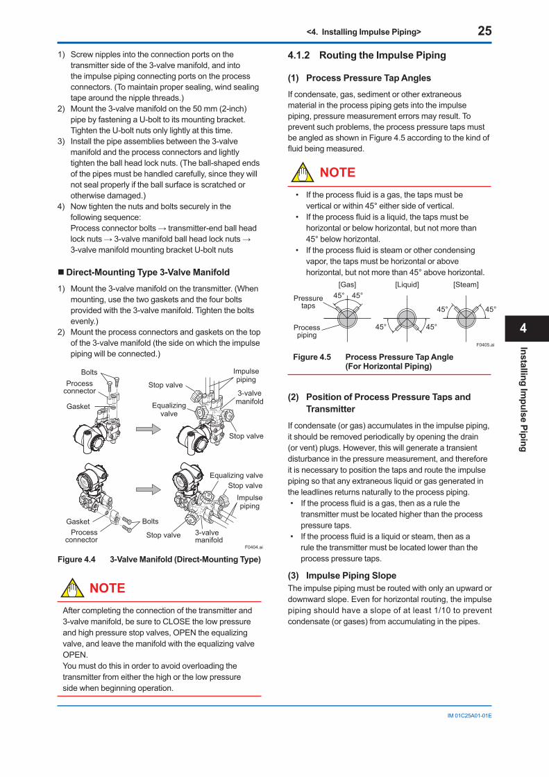
1) Screwnipplesintotheconnectionportsonthetransmittersideofthe3-valvemanifold,andintotheimpulsepipingconnectingportsontheprocessconnectors.(Tomaintainpropersealing,windsealingtapearoundthenipplethreads.)
2) Mountthe3-valvemanifoldonthe50mm(2-inch)pipebyfasteningaU-bolttoitsmountingbracket.TightentheU-boltnutsonlylightlyatthistime.
3) Installthepipeassembliesbetweenthe3-valvemanifoldandtheprocessconnectorsandlightlytightentheballheadlocknuts.(Theball-shapedendsofthepipesmustbehandledcarefully,sincetheywillnotsealproperlyiftheballsurfaceisscratchedorotherwisedamaged.)
4) Nowtightenthenutsandboltssecurelyinthefollowingsequence: Processconnectorbolts→transmitter-endballheadlocknuts→3-valvemanifoldballheadlocknuts→3-valvemanifoldmountingbracketU-boltnuts
Direct-Mounting Type 3-Valve Manifold
1) Mountthe3-valvemanifoldonthetransmitter.(Whenmounting,usethetwogasketsandthefourboltsprovidedwiththe3-valvemanifold.Tightentheboltsevenly.)
2) Mounttheprocessconnectorsandgasketsonthetopofthe3-valvemanifold(thesideonwhichtheimpulsepipingwillbeconnected.)
BoltsProcess
connector
Gasket
GasketProcess
connector
Bolts
Stop valve
Stop valve
3-valvemanifold
3-valvemanifold
Equalizing valve
Equalizingvalve
Stop valveImpulsepiping
Impulsepiping
Stop valve
F0404.ai
Figure 4.4 3-Valve Manifold (Direct-Mounting Type)
NOTEAftercompletingtheconnectionofthetransmitterand3-valvemanifold,besuretoCLOSEthelowpressureandhighpressurestopvalves,OPENtheequalizingvalve,andleavethemanifoldwiththeequalizingvalveOPEN.Youmustdothisinordertoavoidoverloadingthetransmitterfromeitherthehighorthelowpressuresidewhenbeginningoperation.
4.1.2 Routing the Impulse Piping
(1) Process Pressure Tap Angles
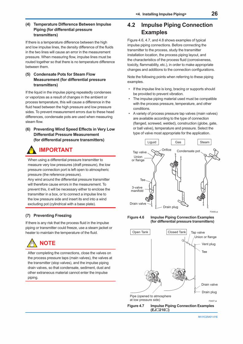
Ifcondensate,gas,sedimentorotherextraneousmaterialintheprocesspipinggetsintotheimpulsepiping,pressuremeasurementerrorsmayresult.Topreventsuchproblems,theprocesspressuretapsmustbeangledasshowninFigure4.5accordingtothekindoffluidbeingmeasured.
NOTE• Iftheprocessfluidisagas,thetapsmustbe
verticalorwithin45°eithersideofvertical.• Iftheprocessfluidisaliquid,thetapsmustbe
horizontalorbelowhorizontal,butnotmorethan45°belowhorizontal.
• Iftheprocessfluidissteamorothercondensingvapor,thetapsmustbehorizontalorabovehorizontal,butnotmorethan45°abovehorizontal.
[Gas]
Pressuretaps
Processpiping
[Steam][Liquid]
45°
45°
45° 45°
45°
45°
F0405.ai
Figure 4.5 Process Pressure Tap Angle (For Horizontal Piping)
(2) Position of Process Pressure Taps and Transmitter
Ifcondensate(orgas)accumulatesintheimpulsepiping,itshouldberemovedperiodicallybyopeningthedrain(orvent)plugs.However,thiswillgenerateatransientdisturbanceinthepressuremeasurement,andthereforeitisnecessarytopositionthetapsandroutetheimpulsepipingsothatanyextraneousliquidorgasgeneratedintheleadlinesreturnsnaturallytotheprocesspiping.• Iftheprocessfluidisagas,thenasarulethe
transmittermustbelocatedhigherthantheprocesspressure taps.
• Iftheprocessfluidisaliquidorsteam,thenasarulethetransmittermustbelocatedlowerthantheprocess pressure taps.
(3) Impulse Piping SlopeTheimpulsepipingmustberoutedwithonlyanupwardordownwardslope.Evenforhorizontalrouting,theimpulsepipingshouldhaveaslopeofatleast1/10topreventcondensate(orgases)fromaccumulatinginthepipes.
Installing Impulse Piping
4
<4. Installing Impulse Piping> 26
IM01C25A01-01E
(4) Temperature Difference Between Impulse Piping (for differential pressure transmitters)
Ifthereisatemperaturedifferencebetweenthehighandlowimpulselines,thedensitydifferenceofthefluidsinthetwolineswillcauseanerrorinthemeasurementpressure.Whenmeasuringflow,impulselinesmustberoutedtogethersothatthereisnotemperaturedifferencebetweenthem.
(5) Condensate Pots for Steam Flow Measurement (for differential pressure transmitters)
Iftheliquidintheimpulsepipingrepeatedlycondensesorvaporizesasaresultofchangesintheambientorprocesstemperature,thiswillcauseadifferenceinthefluidheadbetweenthehighpressureandlowpressuresides.Topreventmeasurementerrorsduetotheseheaddifferences,condensatepotsareusedwhenmeasuringsteamflow.
(6) Preventing Wind Speed Effects in Very Low Differential Pressure Measurement (for differential pressure transmitters)
IMPORTANTWhenusingadifferentialpressuretransmittertomeasureverylowpressures(draftpressure),thelowpressureconnectionportisleftopentoatmosphericpressure(thereferencepressure).Anywindaroundthedifferentialpressuretransmitterwillthereforecauseerrorsinthemeasurement.Topreventthis,itwillbenecessaryeithertoenclosethetransmitterinabox,ortoconnectaimpulselinetothelowpressuresideandinsertitsendintoawindexcludingpot(cylindricalwithabaseplate).
(7) Preventing Freezing
Ifthereisanyriskthattheprocessfluidintheimpulsepipingortransmittercouldfreeze,useasteamjacketorheatertomaintainthetemperatureofthefluid.
NOTEAftercompletingtheconnections,closethevalvesontheprocesspressuretaps(mainvalves),thevalvesatthetransmitter(stopvalves),andtheimpulsepipingdrainvalves,sothatcondensate,sediment,dustandotherextraneousmaterialcannotentertheimpulsepiping.
4.2 Impulse Piping Connection Examples
Figure4.6,4.7,and4.8showsexamplesoftypicalimpulsepipingconnections.Beforeconnectingthetransmittertotheprocess,studythetransmitterinstallationlocation,theprocesspipinglayout,andthecharacteristicsoftheprocessfluid(corrosiveness,toxicity,flammability,etc.),inordertomakeappropriatechangesandadditionstotheconnectionconfigurations.
Notethefollowingpointswhenreferringtothesepipingexamples.
• Iftheimpulselineislong,bracingorsupportsshouldbeprovidedtopreventvibration.
• Theimpulsepipingmaterialusedmustbecompatiblewiththeprocesspressure,temperature,andotherconditions.
• Avarietyofprocesspressuretapvalves(mainvalves)areavailableaccordingtothetypeofconnection(flanged,screwed,welded),construction(globe,gate,orballvalve),temperatureandpressure.Selectthetypeofvalvemostappropriatefortheapplication.
Tee
3-valvemanifold
Drain valve
Orifice
Drain plug
Tap valveUnion
or flange
Liguid Gas
Condensate pot
Steam
F0406.ai
Figure 4.6 Impulse Piping Connection Examples (for differential pressure transmitters)
F0407.ai
Pipe (opened to atmosphereat low pressure side)
Open Tank Closed Tank Tap valveUnion or flange
Vent plug
Tee
Drain valve
Drain plug
Figure 4.7 Impulse Piping Connection Examples (EJ210)
<4. Installing Impulse Piping> 27
IM01C25A01-01E
F0408.ai
Liquid Gas Steam
Union or flange
TeeTee
Drain plug
Drain valve
Drain valveDrain plug
Union or flange
Union or flange
Union or flange
Tap valve
Tap valve
Tee
Drain valveDrain plug
Tap valve
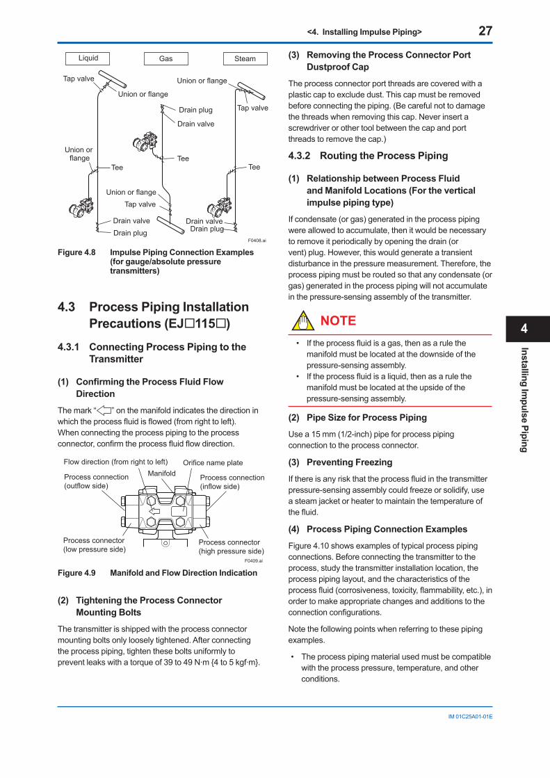
Figure 4.8 Impulse Piping Connection Examples (for gauge/absolute pressure transmitters)
4.3 Process Piping Installation Precautions (EJ115)
4.3.1 Connecting Process Piping to the Transmitter
(1) ConfirmingtheProcessFluidFlowDirection
Themark“ ”onthemanifoldindicatesthedirectioninwhichtheprocessfluidisflowed(fromrighttoleft).Whenconnectingtheprocesspipingtotheprocessconnector,confirmtheprocessfluidflowdirection.
F0409.ai
Flow direction (from right to left)Manifold
Orifice name plate
Process connector(low pressure side)
Process connector(high pressure side)
Process connection(outflow side)
Process connection(inflow side)
Figure 4.9 Manifold and Flow Direction Indication
(2) Tightening the Process Connector Mounting Bolts
Thetransmitterisshippedwiththeprocessconnectormountingboltsonlylooselytightened.Afterconnectingtheprocesspiping,tightentheseboltsuniformlytopreventleakswithatorqueof39to49N·m4to5kgf·m.
(3) Removing the Process Connector Port Dustproof Cap
Theprocessconnectorportthreadsarecoveredwithaplasticcaptoexcludedust.Thiscapmustberemovedbeforeconnectingthepiping.(Becarefulnottodamagethethreadswhenremovingthiscap.Neverinsertascrewdriverorothertoolbetweenthecapandportthreadstoremovethecap.)
4.3.2 Routing the Process Piping
(1) Relationship between Process Fluid and Manifold Locations (For the vertical impulse piping type)
Ifcondensate(orgas)generatedintheprocesspipingwereallowedtoaccumulate,thenitwouldbenecessarytoremoveitperiodicallybyopeningthedrain(orvent)plug.However,thiswouldgenerateatransientdisturbanceinthepressuremeasurement.Therefore,theprocesspipingmustberoutedsothatanycondensate(orgas)generatedintheprocesspipingwillnotaccumulateinthepressure-sensingassemblyofthetransmitter.
NOTE• Iftheprocessfluidisagas,thenasarulethe
manifoldmustbelocatedatthedownsideofthepressure-sensingassembly.
• Iftheprocessfluidisaliquid,thenasarulethemanifoldmustbelocatedattheupsideofthepressure-sensingassembly.
(2) Pipe Size for Process Piping
Usea15mm(1/2-inch)pipeforprocesspipingconnectiontotheprocessconnector.
(3) Preventing Freezing
Ifthereisanyriskthattheprocessfluidinthetransmitterpressure-sensingassemblycouldfreezeorsolidify,useasteamjacketorheatertomaintainthetemperatureofthefluid.
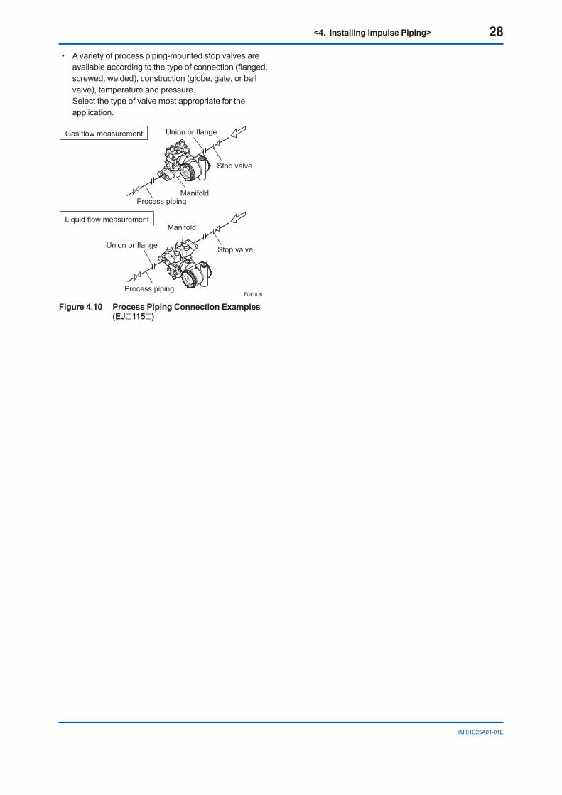
(4) Process Piping Connection Examples
Figure4.10showsexamplesoftypicalprocesspipingconnections.Beforeconnectingthetransmittertotheprocess,studythetransmitterinstallationlocation,theprocesspipinglayout,andthecharacteristicsoftheprocessfluid(corrosiveness,toxicity,flammability,etc.),inordertomakeappropriatechangesandadditionstotheconnectionconfigurations.
Notethefollowingpointswhenreferringtothesepipingexamples.
• Theprocesspipingmaterialusedmustbecompatiblewiththeprocesspressure,temperature,andotherconditions.
Installing Impulse Piping
4
<4. Installing Impulse Piping> 28
IM01C25A01-01E
• Avarietyofprocesspiping-mountedstopvalvesareavailableaccordingtothetypeofconnection(flanged,screwed,welded),construction(globe,gate,orballvalve),temperatureandpressure. Selectthetypeofvalvemostappropriatefortheapplication.
Gas flow measurement
Liquid flow measurement
Union or flange
Union or flange
Stop valve
Stop valve
Manifold
Manifold
Process piping
Process pipingF0410.ai
Figure 4.10 Process Piping Connection Examples (EJ115)
<5. Wiring> 29
IM01C25A01-01E
5. Wiring
NOTEFor FOUNDATIONFieldbusPROFIBUSPA,andModbuscommunicationtypes,pleaserefertomanualsintheattachedCD-ROM.
5.1 Wiring Precautions
IMPORTANT• Laywiringasfaraspossiblefromelectricalnoise
sourcessuchaslargecapacitytransformers,motors,andpowersupplies.
• Removeelectricalconnectiondustcapbeforewiring.
• Allthreadedpartsmustbetreatedwithwaterproofingsealant.(Anon-hardeningsiliconegroup sealant is recommended.)
• Topreventnoisepickup,donotpasssignalandpowercablesthroughthesameducts.
• Explosion-protectedinstrumentsmustbewiredinaccordancewithspecificrequirements(and,incertaincountries,legalregulations)inordertopreservetheeffectivenessoftheirexplosion-protected features.
• TheterminalboxcoverislockedbyanAllenheadbolt(ashroudingbolt)onATEXflameprooftypetransmitters.WhentheshroudingboltisdrivenclockwiseusinganAllenwrench,itgosein.Thecoverlockcanthenbereleasedandthecovercanbeopenedbyhand. Whenacoveriscloseditshouldbelockedbyashroudingboltwithoutfail.Tightentheshroudingbolttoatorqueof0.7N·m.
Shrouding Bolt
Shrouding BoltF0501.ai
Figure 5.1 Shrouding Bolt
• Plugandsealanunusedconduitconnection.
5.2 Connections of External Wiring to Terminal Box
F0527.ai
RTD cable connection*
Terminal Configuration
1Terminal 2Terminal
3Terminal [A]
[B]*
*For EJX9A only.
4Terminal
Power supply and output terminals
External indicator (ammeter) terminals*1*2
orStatus contact output terminals*2
(when /AL is specified)
Terminal Wiring for 4 to 20 mA outputSUPPLY
CHECKor
ALARM
+–+– +–
Ground terminal
12
2
2
3
3
F0531.ai
SUPPLY
VOUT
+–+–
Terminal Wiring for 1 to 5 V output
Ground terminal
Power supply terminals
1 to 5 V DC with HART communication terminals
12
23
*1: When using an external indicator or check meter, the internal resistance must be 10 Ω or less. A check meter or indicator cannot be connected when /AL option is specified.
*2: Not available for FOUNDATION Fieldbus and PROFIBUS PA communication types.
SUPPLY
CHECK
PULSE
+–
*1: When using an external indicator or check meter, the internal resistance must be 10Ω or less.*2: Not available for FOUNDATION Fieldbus communication type.
+–+–
Terminal Wiring for 4 to 20 mA output [EJX9A]
Ground terminal
Power supply and output terminals
External indicator (ammeter) terminals *1*2
Pulse or status contact output terminals *2
12
23
24
Figure 5.2 Terminal
Wiring
5
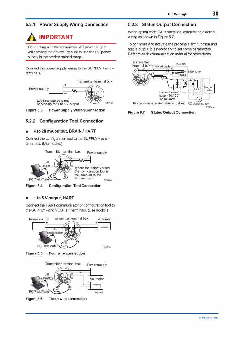
<5. Wiring> 30
IM01C25A01-01E
5.2.1 Power Supply Wiring Connection
IMPORTANTConnectingwiththecommercialACpowersupplywilldamagethedevice.BesuretousetheDCpowersupplyinthepredeterminedrange.
ConnectthepowersupplywiringtotheSUPPLY+and–terminals.
Power supply–
+Transmitter terminal box
F0502.aiLoad resistance is not necessary for 1 to 5 V output.
Figure 5.3 Power Supply Wiring Connection
5.2.2 ConfigurationToolConnection
4to20mAoutput,BRAIN/HART
ConnecttheconfigurationtooltotheSUPPLY+and–terminals.(Usehooks.)
Transmitter terminal box
F0503.ai
Power supply
–
+
Ignore the polarity since the configuration tool is AC-coupled to the terminal box.
USBFieldMate Modem
PC/FieldMate
Figure5.4 ConfigurationToolConnection
1to5Voutput,HART
ConnecttheHARTcommunicatororconfigurationtooltotheSUPPLY-andVOUT(+)terminals.(Usehooks.)
Transmitter terminal box
F0532.ai
Voltmeter
–
+Power supply
–
+
USBFieldMate Modem
PC/FieldMate
Figure 5.5 Four wire connection
Transmitter terminal box
F0533.ai
Power supply
–
+
Voltmeter
–
+
USBFieldMate Modem
PC/FieldMate
Figure 5.6 Three wire connection
5.2.3 Status Output ConnectionWhenoptioncode/ALisspecified,connecttheexternalwiringasshowninFigure5.7.
Toconfigureandactivatetheprocessalarmfunctionandstatusoutput,itisnecessarytosetsomeparameters.Refertoeachcommunicationmanualforprocedures.
Transmitter terminal box
Magnetic valve
AC power supply
External power supply 30V DC, 120mA max
+
– 250Ω
24V DC
Use two-wire separately shielded cables.
Distributor
Shielded cable
F0504.ai
Figure 5.7 Status Output Connection
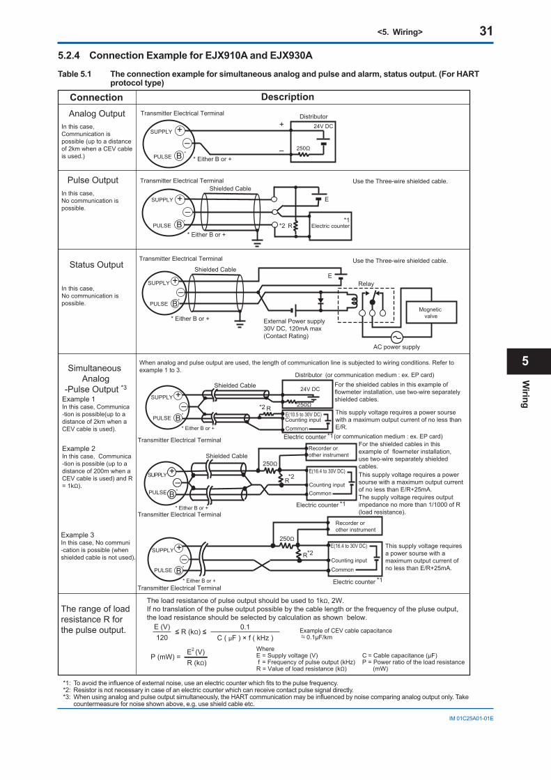
<5. Wiring> 31
IM01C25A01-01E
5.2.4 Connection Example for EJX910A and EJX930A
Table 5.1 The connection example for simultaneous analog and pulse and alarm, status output. (For HART protocol type)
250Ω
R +
–BPULSE
SUPPLY
Transmitter Electrical Terminal
Recorder or other instrument
This supply voltage requires a power sourse with a maximum output current of no less than E/R+25mA.
Electric counter
E(16.4 to 30V DC)
Counting input
Common
+
B
Transmitter Electrical Terminal
250Ω
24V DC
PULSE
SUPPLY+
–
Distributor
–
+–
BPULSE
SUPPLY
R
E
Transmitter Electrical Terminal Use the Three-wire shielded cable.
Use the Three-wire shielded cable.
Electric counter*1
*1
*1
*1
*2
*2
*2
*2
Shielded Cable
Shielded Cable
PULSE
SUPPLY +–
BMognetic
valve
AC power supply
External Power supply 30V DC, 120mA max(Contact Rating)
Transmitter Electrical Terminal
E
250Ω
R+
–BPULSE
SUPPLY
Counting inputCommon
For the shielded cables in this example of flowmeter installation, use two-wire separately shielded cables.This supply voltage requires a power sourse with a maximum output current of no less than E/R+25mA.
Recorder or other instrument
Electric counter
E(16.4 to 30V DC)
Shielded Cable
The supply voltage requires output impedance no more than 1/1000 of R (load resistance).Transmitter Electrical Terminal
250ΩRE(10.5 to 30V DC) Counting inputCommon
24V DC
PULSE
SUPPLY
For the shielded cables in this example of flowmeter installation, use two-wire separately shielded cables.
This supply voltage requires a power sourse with a maximum output current of no less than E/R.
Distributor (or communication medium : ex. EP card)
(or communication medium : ex. EP card)Electric counter
+–
B
Shielded Cable
Transmitter Electrical Terminal
When analog and pulse output are used, the length of communication line is subjected to wiring conditions. Refer to example 1 to 3.
Relay
* Either B or +*
* Either B or +
*
* Either B or +
* Either B or +
* Either B or +
* Either B or +
*
*
*
*
Analog Output
Pulse Output
Status Output
Simultaneous Analog
-Pulse Output *3
DescriptionConnection
0.1 C ( µF ) × f ( kHz )
≤ R (kΩ) ≤120
E (V)
The load resistance of pulse output should be used to 1kΩ, 2W.If no translation of the pulse output possible by the cable length or the frequency of the pluse output,the load resistance should be selected by calculation as shown below.
Example of CEV cable capacitance 0.1µF/km
WhereE = Supply voltage (V) f = Frequency of pulse output (kHz)R = Value of load resistance (kΩ)
C = Cable capacitance (µF) P = Power ratio of the load resistance (mW)
P (mW) =R (kΩ)E2 (V)
Example 3In this case, No communi-cation is possible (when shielded cable is not used).
The range of load resistance R for the pulse output.
Example 1In this case, Communica-tion is possible(up to adistance of 2km when aCEV cable is used).
Example 2In this case, Communica-tion is possible (up to adistance of 200m when a CEV cable is used) and R = 1kΩ).
In this case, Communication is possible (up to a distance of 2km when a CEV cable is used.)
In this case, No communication is possible.
In this case, No communication is possible.
*1: Toavoidtheinfluenceofexternalnoise,useanelectriccounterwhichfitstothepulsefrequency.*2: Resistorisnotnecessaryincaseofanelectriccounterwhichcanreceivecontactpulsesignaldirectly.*3:Whenusinganalogandpulseoutputsimultaneously,theHARTcommunicationmaybeinfluencedbynoisecomparinganalogoutputonly.Take
countermeasurefornoiseshownabove,e.g.useshieldcableetc.
Wiring
5
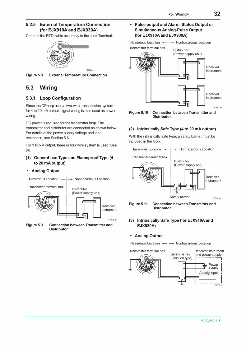
<5. Wiring> 32
IM01C25A01-01E
5.2.5 External Temperature Connection (for EJX910A and EJX930A)
ConnecttheRTDcableassemblytotheJuckTerminal.
F0505.ai
Figure 5.8 External Temperature Connection
5.3 Wiring
5.3.1 LoopConfigurationSincetheDPharpusesatwo-wiretransmissionsystemfor4to20mAoutput,signalwiringisalsousedaspowerwiring.
DCpowerisrequiredforthetransmitterloop.Thetransmitteranddistributorareconnectedasshownbelow.Fordetailsofthepowersupplyvoltageandloadresistance,seeSection5.6.
For1to5Voutput,threeorfourwiresystemisused.See(4).
(1) General-use Type and Flameproof Type (4 to 20 mA output)
• AnalogOutput
Hazardous Location Nonhazardous Location
Transmitter terminal boxDistributor (Power supply unit)
Receiver instrument
F0506.ai
Figure 5.9 Connection between Transmitter and Distributor
• PulseoutputandAlarm,StatusOutputorSimultaneous Analog-Pulse Output (for EJX910A and EJX930A)
Hazardous Location Nonhazardous LocationTransmitter terminal box
Distributor (Power supply unit)
Receiver instrument
Receiver instrument
F0507.ai
Figure 5.10 Connection between Transmitter and Distributor
(2) Intrinsically Safe Type (4 to 20 mA output)
Withtheintrinsicallysafetype,asafetybarriermustbeincludedintheloop.
Hazardous Location Nonhazardous Location
Transmitter terminal boxDistributor (Power supply unit)
Receiver instrument
Safety barrier F0508.ai
Figure 5.11 Connection between Transmitter and Distributor
(3) Intrinsically Safe Type (for EJX910A and EJX930A)
• AnalogOutput
Hazardous Location Nonhazardous Location
Transmitter terminal box Receiver instrument(and power supply)Safety barreir
(Isolation type)
F0509.ai
Anaolg input
Powersupply
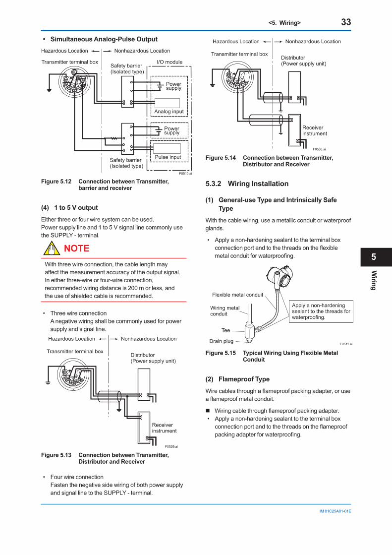
<5. Wiring> 33
IM01C25A01-01E
• SimultaneousAnalog-PulseOutputHazardous Location Nonhazardous Location
Transmitter terminal boxSafety barrier (Isolated type)
I/O module
F0510.ai
Safety barrier (Isolated type)
Power supply
Power supply
Analog input
Pulse input
Figure 5.12 Connection between Transmitter, barrier and receiver
(4) 1 to 5 V output
Eitherthreeorfourwiresystemcanbeused.Power supply line and 1 to 5 V signal line commonly use theSUPPLY-terminal.
NOTEWiththreewireconnection,thecablelengthmayaffectthemeasurementaccuracyoftheoutputsignal.Ineitherthree-wireorfour-wireconnection,recommendedwiringdistanceis200morless,andtheuseofshieldedcableisrecommended.
• Threewireconnection Anegativewiringshallbecommonlyusedforpower
supply and signal line.
F0529.ai
Hazardous Location Nonhazardous Location
Transmitter terminal boxDistributor (Power supply unit)
Receiver instrument
Figure 5.13 Connection between Transmitter, Distributor and Receiver
• Fourwireconnection Fastenthenegativesidewiringofbothpowersupply
andsignallinetotheSUPPLY-terminal.
Hazardous Location Nonhazardous Location
Transmitter terminal boxDistributor (Power supply unit)
Receiver instrument
F0530.ai
Figure 5.14 Connection between Transmitter, Distributor and Receiver
5.3.2 Wiring Installation
(1) General-use Type and Intrinsically Safe Type
Withthecablewiring,useametallicconduitorwaterproofglands.
• Applyanon-hardeningsealanttotheterminalboxconnectionportandtothethreadsontheflexiblemetalconduitforwaterproofing.
F0511.ai
Flexible metal conduit
Wiring metalconduit
Tee
Drain plug
Apply a non-hardeningsealant to the threads forwaterproofing.
Figure 5.15 Typical Wiring Using Flexible Metal Conduit
(2) Flameproof Type
Wirecablesthroughaflameproofpackingadapter,oruseaflameproofmetalconduit.
Wiringcablethroughflameproofpackingadapter.• Applyanon-hardeningsealanttotheterminalbox
connectionportandtothethreadsontheflameproofpackingadapterforwaterproofing.
Wiring
5
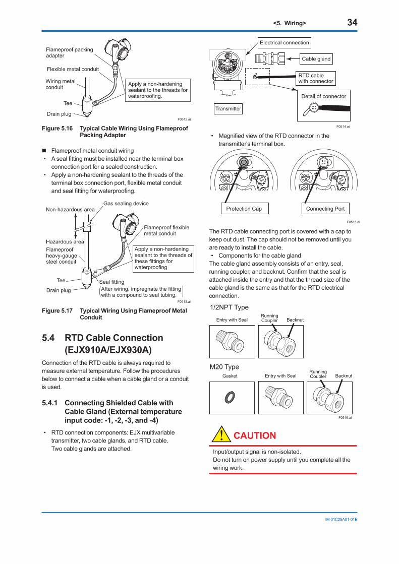
<5. Wiring> 34
IM01C25A01-01E
Flameproof packing adapter
Flexible metal conduit
Wiring metalconduit
Tee
Drain plug
Apply a non-hardeningsealant to the threads forwaterproofing.
F0512.ai
Figure 5.16 Typical Cable Wiring Using Flameproof Packing Adapter
Flameproof metal conduit wiring• Asealfittingmustbeinstalledneartheterminalbox
connection port for a sealed construction.• Applyanon-hardeningsealanttothethreadsofthe
terminalboxconnectionport,flexiblemetalconduitandsealfittingforwaterproofing.
F0513.ai
Non-hazardous area
Hazardous areaFlameproofheavy-gaugesteel conduit
Tee
Drain plugSeal fitting
Gas sealing device
Flameproof flexiblemetal conduit
Apply a non-hardeningsealant to the threads ofthese fittings forwaterproofing
After wiring, impregnate the fittingwith a compound to seal tubing.
Figure 5.17 Typical Wiring Using Flameproof Metal Conduit
5.4 RTD Cable Connection (EJX910A/EJX930A)
ConnectionoftheRTDcableisalwaysrequiredtomeasureexternaltemperature.Followtheproceduresbelowtoconnectacablewhenacableglandoraconduitis used.
5.4.1 Connecting Shielded Cable with Cable Gland (External temperature input code: -1, -2, -3, and -4)
• RTDconnectioncomponents:EJXmultivariabletransmitter,twocableglands,andRTDcable. Twocableglandsareattached.
Transmitter
Cable gland
Electrical connection
RTD cable with connector
Detail of connector
F0514.ai
• MagnifiedviewoftheRTDconnectorinthetransmitter'sterminalbox.
ALARM ALARM
Protection Cap Connecting Port
F0515.ai
TheRTDcableconnectingportiscoveredwithacaptokeepoutdust.Thecapshouldnotberemoveduntilyouarereadytoinstallthecable.• ComponentsforthecableglandThecableglandassemblyconsistsofanentry,seal,runningcoupler,andbacknut.ConfirmthatthesealisattachedinsidetheentryandthatthethreadsizeofthecableglandisthesameasthatfortheRTDelectricalconnection.
F0516.ai
1/2NPT Type
M20 Type Gasket
Entry with Seal Running Coupler Backnut
Entry with Seal Running Coupler Backnut
CAUTIONInput/outputsignalisnon-isolated. Donotturnonpowersupplyuntilyoucompleteallthewiringwork.
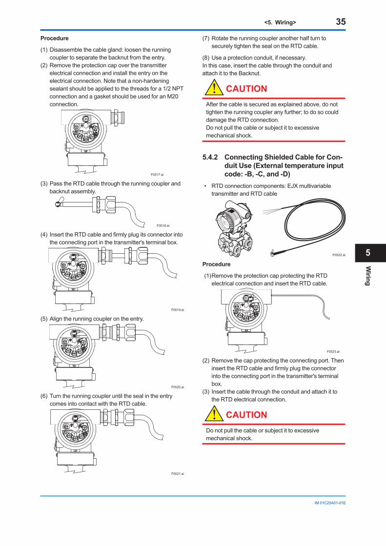
<5. Wiring> 35
IM01C25A01-01E
Procedure
(1)Disassemblethecablegland:loosentherunningcouplertoseparatethebacknutfromtheentry.
(2)Removetheprotectioncapoverthetransmitterelectricalconnectionandinstalltheentryontheelectricalconnection.Notethatanon-hardeningsealantshouldbeappliedtothethreadsfora1/2NPTconnectionandagasketshouldbeusedforanM20connection.
F0517.ai
(3)PasstheRTDcablethroughtherunningcouplerandbacknutassembly.
F0518.ai
(4) InserttheRTDcableandfirmlyplugitsconnectorintotheconnectingportinthetransmitter'sterminalbox.
F0519.ai
(5)Aligntherunningcouplerontheentry.
F0520.ai
(6)TurntherunningcoupleruntilthesealintheentrycomesintocontactwiththeRTDcable.
F0521.ai
(7)RotatetherunningcoupleranotherhalfturntosecurelytightenthesealontheRTDcable.
(8)Useaprotectionconduit,ifnecessary.Inthiscase,insertthecablethroughtheconduitandattachittotheBacknut.
CAUTIONAfterthecableissecuredasexplainedabove,donottightentherunningcoupleranyfurther;todosocoulddamagetheRTDconnection. Donotpullthecableorsubjectittoexcessivemechanicalshock.
5.4.2 Connecting Shielded Cable for Con-duit Use (External temperature input code: -B, -C, and -D)
• RTDconnectioncomponents:EJXmultivariabletransmitterandRTDcable
F0522.ai
Procedure
(1)RemovetheprotectioncapprotectingtheRTDelectricalconnectionandinserttheRTDcable.
F0523.ai
(2)Removethecapprotectingtheconnectingport.TheninserttheRTDcableandfirmlyplugtheconnectorintotheconnectingportinthetransmitter'sterminalbox.
(3) InsertthecablethroughtheconduitandattachittotheRTDelectricalconnection.
CAUTIONDonotpullthecableorsubjectittoexcessivemechanicalshock.
Wiring
5
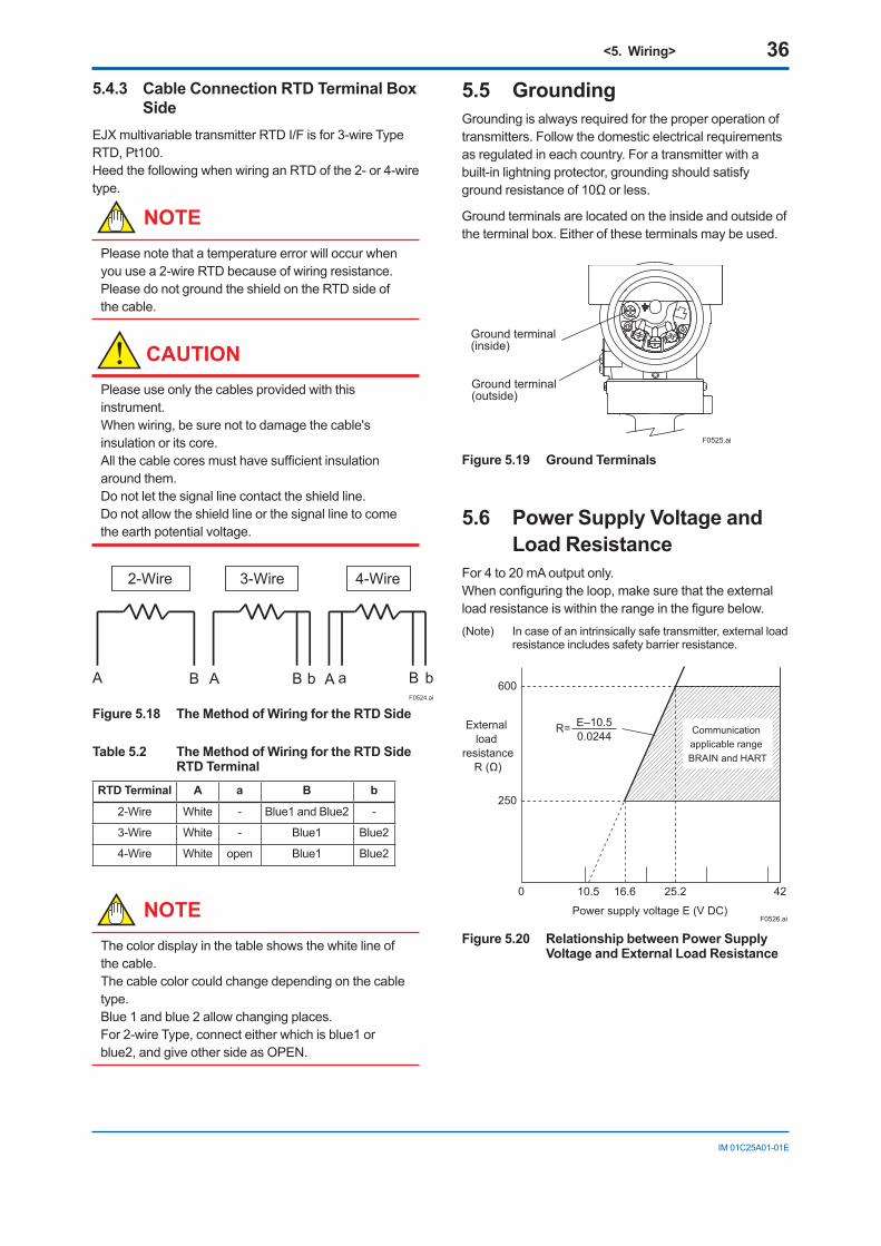
<5. Wiring> 36
IM01C25A01-01E
5.4.3 Cable Connection RTD Terminal Box Side
EJXmultivariabletransmitterRTDI/Fisfor3-wireTypeRTD,Pt100.HeedthefollowingwhenwiringanRTDofthe2-or4-wiretype.
NOTEPleasenotethatatemperatureerrorwilloccurwhenyouusea2-wireRTDbecauseofwiringresistance. PleasedonotgroundtheshieldontheRTDsideofthecable.
CAUTIONPleaseuseonlythecablesprovidedwiththisinstrument. Whenwiring,besurenottodamagethecable'sinsulation or its core. Allthecablecoresmusthavesufficientinsulationaroundthem. Donotletthesignallinecontacttheshieldline. Donotallowtheshieldlineorthesignallinetocometheearthpotentialvoltage.
2-Wire 3-Wire 4-Wire
A B A B b A B baF0524.ai
Figure 5.18 The Method of Wiring for the RTD Side
Table 5.2 The Method of Wiring for the RTD Side RTD Terminal
RTD Terminal A a B b
2-Wire White - Blue1andBlue2 -
3-Wire White - Blue1 Blue2
4-Wire White open Blue1 Blue2
NOTEThecolordisplayinthetableshowsthewhitelineofthecable. Thecablecolorcouldchangedependingonthecabletype. Blue1andblue2allowchangingplaces. For2-wireType,connecteitherwhichisblue1orblue2,andgiveothersideasOPEN.
5.5 GroundingGroundingisalwaysrequiredfortheproperoperationoftransmitters.Followthedomesticelectricalrequirementsasregulatedineachcountry.Foratransmitterwithabuilt-inlightningprotector,groundingshouldsatisfygroundresistanceof10Ωorless.
Groundterminalsarelocatedontheinsideandoutsideoftheterminalbox.Eitheroftheseterminalsmaybeused.
Ground terminal(inside)
Ground terminal(outside)
F0525.ai
Figure 5.19 Ground Terminals
5.6 Power Supply Voltage and Load Resistance
For 4 to 20 mA output only.Whenconfiguringtheloop,makesurethattheexternalloadresistanceiswithintherangeinthefigurebelow.
(Note) Incaseofanintrinsicallysafetransmitter,externalloadresistanceincludessafetybarrierresistance.
600
250
0 10.5 16.6 25.2 42
External load
resistanceR (Ω)
Power supply voltage E (V DC)F0526.ai
Communication applicable range BRAIN and HART
R= E–10.50.0244
Figure 5.20 Relationship between Power Supply Voltage and External Load Resistance
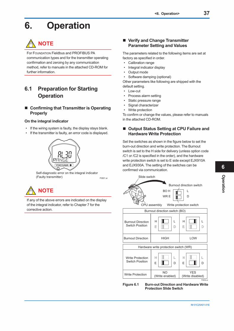
<6. Operation> 37
IM01C25A01-01E
6. Operation
NOTEFor FOUNDATIONFieldbusandPROFIBUSPAcommunication types and forthetransmitteroperatingconfirmationandzeroingbyanycommunicationmethod,refertomanualsintheattachedCD-ROMforfurtherinformation.
6.1 Preparation for Starting Operation
ConfirmingthatTransmitterisOperatingProperly
On the integral indicator
• Ifthewiringsystemisfaulty,thedisplaystaysblank.• Ifthetransmitterisfaulty,anerrorcodeisdisplayed.
Self-diagnostic error on the integral indicator(Faulty transmitter) F0601.ai
NOTEIfanyoftheaboveerrorsareindicatedonthedisplayoftheintegralindicator,refertoChapter7forthecorrective action.
Verify and Change Transmitter Parameter Setting and Values
Theparametersrelatedtothefollowingitemsaresetatfactoryasspecifiedinorder.• Calibrationrange• Integralindicatordisplay• Outputmode• Softwaredamping(optional)Otherparameterslikefollowingareshippedwiththedefault setting.• Low-cut• Processalarmsetting• Staticpressurerange• Signalcharacterizer• WriteprotectionToconfirmorchangethevalues,pleaserefertomanualsintheattachedCD-ROM.
Output Status Setting at CPU Failure and Hardware Write Protection
Settheswitchesasshowninthefigurebelowtosettheburn-outdirectionandwriteprotection.TheBurnoutswitchissettotheHsidefordelivery(unlessoptioncode/C1or/C2isspecifiedintheorder),andthehardwarewriteprotectionswitchissettoEsideexceptEJX910AandEJX930A.Thesettingoftheswitchescanbeconfirmedviacommunication.
F0602.ai
H L H L
Slide switch
CPU assembly
BO H L
WR E D
Burnout direction switch
Write protection switch
H L H L
E D E D
Hardware write protection switch (WR)
Write ProtectionSwitch Position
HIGH LOW
Burnout direction switch (BO)
Burnout Direction
Burnout DirectionSwitch Position
YES(Write disabled)
NO(Write enabled)Write Protection
Figure 6.1 Burn-out Direction and Hardware Write Protection Slide Switch
Operation
6
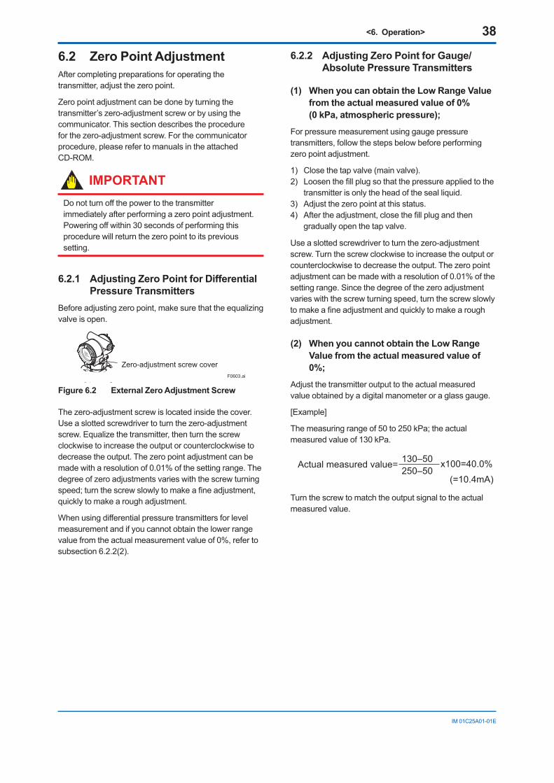
<6. Operation> 38
IM01C25A01-01E
6.2 Zero Point AdjustmentAftercompletingpreparationsforoperatingthetransmitter,adjustthezeropoint.
Zeropointadjustmentcanbedonebyturningthetransmitter’szero-adjustmentscreworbyusingthecommunicator.Thissectiondescribestheprocedureforthezero-adjustmentscrew.Forthecommunicatorprocedure,pleaserefertomanualsintheattachedCD-ROM.
IMPORTANTDonotturnoffthepowertothetransmitterimmediatelyafterperformingazeropointadjustment.Poweringoffwithin30secondsofperformingthisprocedurewillreturnthezeropointtoitsprevioussetting.
6.2.1 Adjusting Zero Point for Differential Pressure Transmitters
Beforeadjustingzeropoint,makesurethattheequalizingvalve is open.
Zero-adjustment screw coverF0603.ai
Figure 6.2 External Zero Adjustment Screw
Thezero-adjustmentscrewislocatedinsidethecover. Useaslottedscrewdrivertoturnthezero-adjustmentscrew.Equalizethetransmitter,thenturnthescrewclockwisetoincreasetheoutputorcounterclockwisetodecreasetheoutput.Thezeropointadjustmentcanbemadewitharesolutionof0.01%ofthesettingrange.Thedegreeofzeroadjustmentsvarieswiththescrewturningspeed;turnthescrewslowlytomakeafineadjustment,quicklytomakearoughadjustment.
Whenusingdifferentialpressuretransmittersforlevelmeasurementandifyoucannotobtainthelowerrangevaluefromtheactualmeasurementvalueof0%,refertosubsection6.2.2(2).
6.2.2 Adjusting Zero Point for Gauge/Absolute Pressure Transmitters
(1) When you can obtain the Low Range Value from the actual measured value of 0% (0 kPa, atmospheric pressure);
For pressure measurement using gauge pressure transmitters,followthestepsbelowbeforeperformingzeropointadjustment.
1) Closethetapvalve(mainvalve).2) Loosenthefillplugsothatthepressureappliedtothe
transmitterisonlytheheadofthesealliquid.3) Adjustthezeropointatthisstatus.4) Aftertheadjustment,closethefillplugandthen
graduallyopenthetapvalve.
Useaslottedscrewdrivertoturnthezero-adjustmentscrew.Turnthescrewclockwisetoincreasetheoutputorcounterclockwisetodecreasetheoutput.Thezeropointadjustmentcanbemadewitharesolutionof0.01%ofthesettingrange.Sincethedegreeofthezeroadjustmentvarieswiththescrewturningspeed,turnthescrewslowlytomakeafineadjustmentandquicklytomakearoughadjustment.
(2) When you cannot obtain the Low Range Value from the actual measured value of 0%;
Adjustthetransmitteroutputtotheactualmeasuredvalueobtainedbyadigitalmanometeroraglassgauge.
[Example]
Themeasuringrangeof50to250kPa;theactualmeasuredvalueof130kPa.
130–50250–50
Actual measured value= x100=40.0%(=10.4mA)
Turnthescrewtomatchtheoutputsignaltotheactualmeasured value.
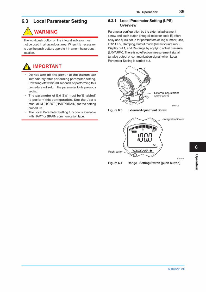
<6. Operation> 39
IM01C25A01-01E
6.3 Local Parameter Setting
WARNING
Thelocalpushbuttonontheintegralindicatormustnotbeusedinahazardousarea.Whenitisnecessarytousethepushbutton,operateitinanon-hazardouslocation.
IMPORTANT• Donotturnoffthepowertothetransmitter
immediately after performing parameter setting. Poweringoffwithin30secondsofperformingthisprocedurewillreturntheparametertoitsprevioussetting.
• TheparameterofExtSWmustbe“Enabled”toperformthisconfiguration.Seetheuser’smanualIM01C25T(HART/BRAIN)forthesettingprocedure.
• TheLocalParameterSettingfunctionisavailablewithHARTorBRAINcommunicationtype.
6.3.1 Local Parameter Setting (LPS) Overview
Parameterconfigurationbytheexternaladjustmentscrewandpushbutton(integralindicatorcodeE)offerseasyandquicksetupforparametersofTagnumber,Unit,LRV,URV,Damping,Outputmode(linear/squareroot),Displayout1,andRe-rangebyapplyingactualpressure(LRV/URV).Thereisnoeffectonmeasurementsignal(analogoutputorcommunicationsignal)whenLocalParameter Setting is carried out.
External adjustmentscrew cover
F0604.ai
Figure 6.3 External Adjustment Screw
Integral indicator
Push-button
F0605.ai
Figure 6.4 Range –Setting Switch (push button)
Operation
6
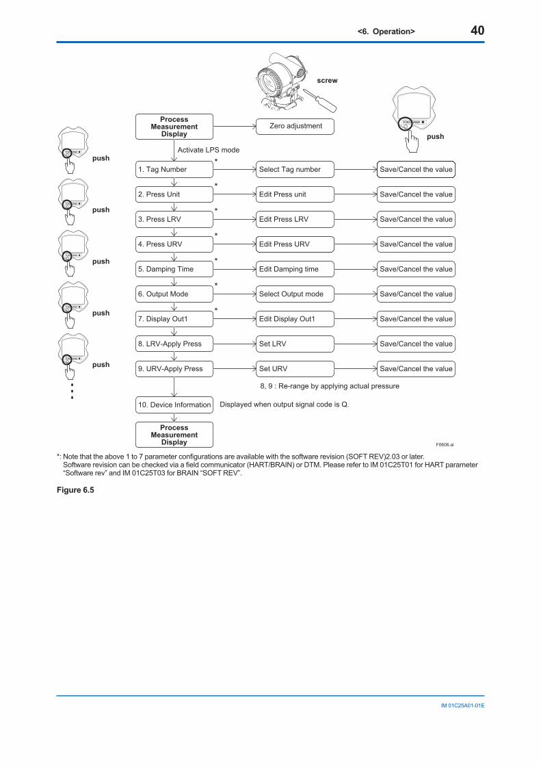
<6. Operation> 40
IM01C25A01-01E
F0606.ai
screw
push
push
push
push
push
push
Save/Cancel the value
Save/Cancel the value
Save/Cancel the value
Save/Cancel the value
Save/Cancel the value
Save/Cancel the value
Save/Cancel the value
Save/Cancel the value
Save/Cancel the value
6. Output Mode
2. Press Unit
1. Tag Number*
*
*
*
*
*
*
3. Press LRV
4. Press URV
7. Display Out1
8. LRV-Apply Press
9. URV-Apply Press
5. Damping Time
Select Output mode
Edit Press unit
Select Tag number
Edit Press LRV
Edit Press URV
Edit Display Out1
Set LRV
Set URV
Edit Damping time
ProcessMeasurement
Display Zero adjustment
ProcessMeasurement
Display
8, 9 : Re-range by applying actual pressure
Displayed when output signal code is Q.10. Device Information
Activate LPS mode
*:Notethattheabove1to7parameterconfigurationsareavailablewiththesoftwarerevision(SOFTREV)2.03orlater. Softwarerevisioncanbecheckedviaafieldcommunicator(HART/BRAIN)orDTM.PleaserefertoIM01C25T01forHARTparameter“Softwarerev”andIM01C25T03forBRAIN“SOFTREV”.
Figure 6.5
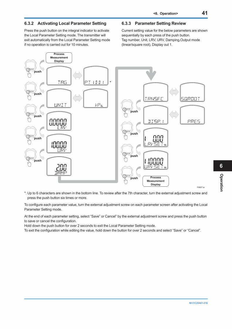
<6. Operation> 41
IM01C25A01-01E
6.3.2 Activating Local Parameter SettingPressthepushbuttonontheintegralindicatortoactivatetheLocalParameterSettingmode.ThetransmitterwillexitautomaticallyfromtheLocalParameterSettingmodeif no operation is carried out for 10 minutes.
6.3.3 Parameter Setting ReviewCurrentsettingvalueforthebelowparametersareshownsequentiallybyeachpressofthepushbutton.Tagnumber,Unit,LRV,URV,Damping,Outputmode(linear/squareroot),Displayout1.
F0607.ai
push
push
push
push
push
ProcessMeasurement
Display
push
push
push
push ProcessMeasurement
Display
*
*:Upto6charactersareshowninthebottomline.Toreviewafterthe7thcharacter,turntheexternaladjustmentscrewandpressthepushbuttonsixtimesormore.
Toconfigureeachparametervalue,turntheexternaladjustmentscrewoneachparameterscreenafteractivatingtheLocalParameter Setting mode.
Attheendofeachparametersetting,select“Save”orCancel”bytheexternaladjustmentscrewandpressthepushbuttontosaveorcanceltheconfiguration. Holddownthepushbuttonforover2secondstoexittheLocalParameterSettingmode. Toexittheconfigurationwhileeditingthevalue,holddownthebuttonforover2secondsandselect“Save”or“Cancel”.
Operation
6
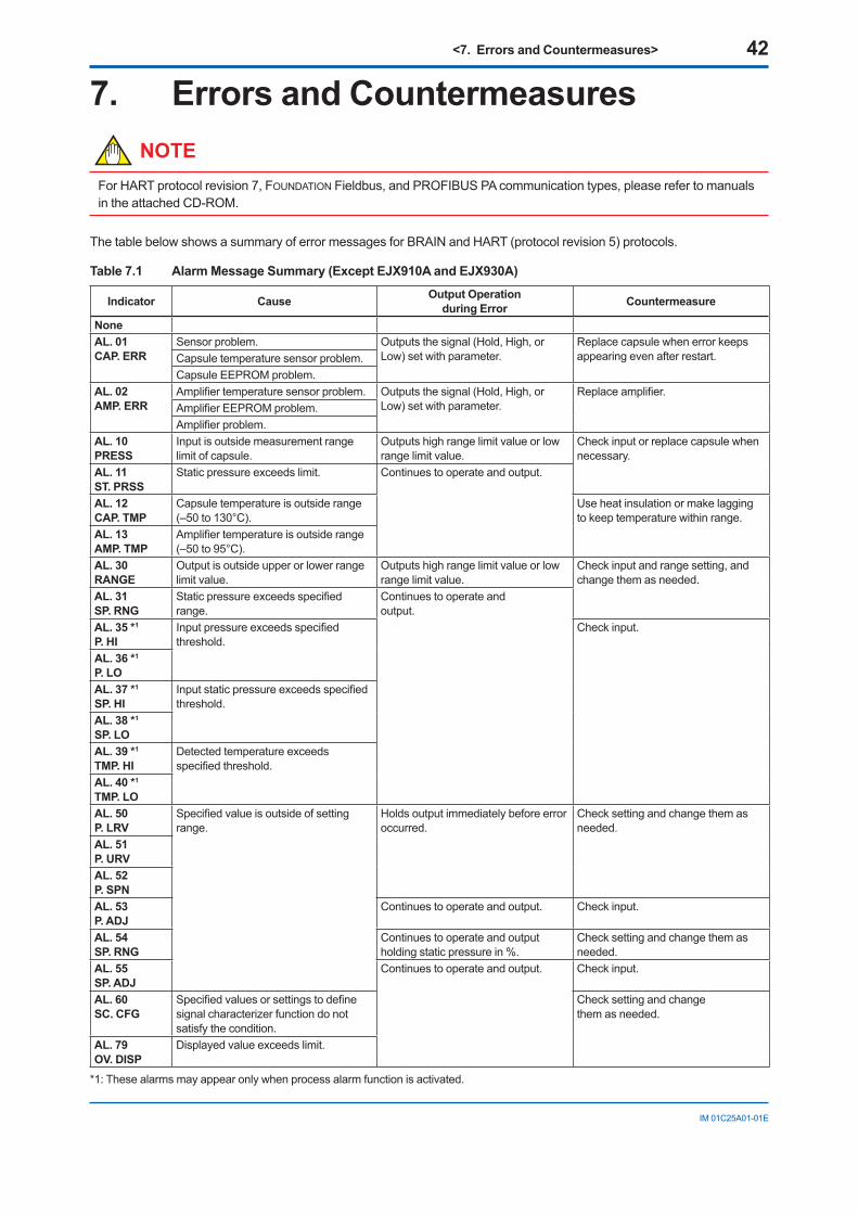
<7. Errors and Countermeasures> 42
IM01C25A01-01E
7. Errors and CountermeasuresNOTE
ForHARTprotocolrevision7,FOUNDATIONFieldbus,andPROFIBUSPAcommunicationtypes,pleaserefertomanualsintheattachedCD-ROM.
ThetablebelowshowsasummaryoferrormessagesforBRAINandHART(protocolrevision5)protocols.
Table 7.1 Alarm Message Summary (Except EJX910A and EJX930A)
Indicator Cause Output Operationduring Error Countermeasure
NoneAL. 01CAP. ERR
Sensorproblem. Outputsthesignal(Hold,High,orLow)setwithparameter.
Replacecapsulewhenerrorkeepsappearing even after restart.Capsuletemperaturesensorproblem.
CapsuleEEPROMproblem.AL. 02AMP. ERR
Amplifiertemperaturesensorproblem. Outputsthesignal(Hold,High,orLow)setwithparameter.
Replaceamplifier.AmplifierEEPROMproblem.Amplifierproblem.
AL. 10PRESS
Inputisoutsidemeasurementrangelimit of capsule.
Outputshighrangelimitvalueorlowrange limit value.
Checkinputorreplacecapsulewhennecessary.
AL. 11ST. PRSS
Staticpressureexceedslimit. Continuestooperateandoutput.
AL. 12CAP. TMP
Capsuletemperatureisoutsiderange(–50to130°C).
Useheatinsulationormakelaggingtokeeptemperaturewithinrange.
AL. 13AMP. TMP
Amplifiertemperatureisoutsiderange(–50to95°C).
AL. 30RANGE
Output is outside upper or lower range limit value.
Outputshighrangelimitvalueorlowrange limit value.
Checkinputandrangesetting,andchangethemasneeded.
AL. 31SP. RNG
Staticpressureexceedsspecifiedrange.
Continuestooperateandoutput.
AL. 35 *1
P. HIInputpressureexceedsspecifiedthreshold.
Checkinput.
AL. 36 *1
P. LOAL. 37 *1
SP. HIInputstaticpressureexceedsspecifiedthreshold.
AL. 38 *1
SP. LOAL. 39 *1
TMP. HIDetectedtemperatureexceedsspecifiedthreshold.
AL. 40 *1
TMP. LOAL. 50P. LRV
Specifiedvalueisoutsideofsettingrange.
Holdsoutputimmediatelybeforeerroroccurred.
Checksettingandchangethemasneeded.
AL. 51P. URVAL. 52P. SPNAL. 53P. ADJ
Continuestooperateandoutput. Checkinput.
AL. 54SP. RNG
Continuestooperateandoutputholdingstaticpressurein%.
Checksettingandchangethemasneeded.
AL. 55SP. ADJ
Continuestooperateandoutput. Checkinput.
AL. 60SC. CFG
Specifiedvaluesorsettingstodefinesignalcharacterizerfunctiondonotsatisfythecondition.
Checksettingandchangethemasneeded.
AL. 79OV. DISP
Displayedvalueexceedslimit.
*1:Thesealarmsmayappearonlywhenprocessalarmfunctionisactivated.
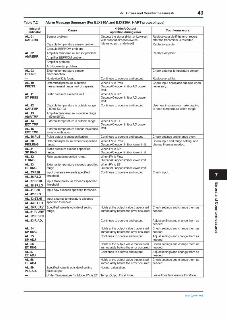
<7. Errors and Countermeasures> 43
IM01C25A01-01E
Table 7.2 Alarm Message Summary (For EJX910A and EJX930A, HART protocol type)
Integral indicator Cause 4-20mA Output
operation during error Countermeasure
AL. 01 CAP.ERR
Sensorproblem. Outputsthesignal(HighorLow)setwithburnoutdirectionswitch. [statusoutput:undefined]
Replacecapsuleiftheerrorrecursafterthetransmitterisrestarted.
Capsuletemperaturesensorproblem. Replace capsule. CapsuleEEPROMproblem.
AL. 02 AMP.ERR
Amplifiertemperaturesensorproblem. Replaceamplifier.AmplifierEEPROMproblem.Amplifierproblem.A/DConverterproblem.
AL. 03 ET.ERR
Externaltemperaturesensordisconnection.
Checkexternaltemperaturesensor.
— NodeviceIDisfound. Continuestooperateandoutput. Replaceamplifier.AL. 10 PRESS
Differential pressure is outside measurement range limit of capsule.
WhenPVisPresOutputAOupperlimitorAOLowerlimit.
Checkinputorreplacecapsulewhennecessary.
AL. 11 ST. PRSS
Staticpressureexceedslimit. WhenPVisSPOutputAOupperlimitorAOLowerlimit.
AL. 12 CAP.TMP
Capsuletemperatureisoutsiderange(–50to130°C).
Continuestooperateandoutput. Useheatinsulationormakelaggingtokeeptemperaturewithinrange.
AL. 13 AMP.TMP
Amplifiertemperatureisoutsiderange(–50to95°C).
AL. 14 EXT. TMP
Externaltemperatureisoutsiderange. WhenPVisETOutputAOupperlimitorAOLowerlimit.AL. 15
EXT. TMP Externaltemperaturesensorresistanceisoutspecification.
AL. 16 PLS Pulseoutputisoutspecification. Continuestooperateandoutput. Checksettingsandchangethem.AL. 30 PRS.RNG
Differentialpressureexceedsspecifiedrange.
WhenPVisPres.Output AO upper limit or lower limit.
Checkinputandrangesetting,andchangethemasneeded.
AL. 31 SP. RNG
Staticpressureexceedsspecifiedrange.
WhenPVisSPOutput AO upper limit or lower limit.
AL. 32 F. RNG
Flowexceedsspecifiedrange. WhenPVisFlowOutput AO upper limit or lower limit.
AL. 33 ET. RNG
Externaltemperatureexceedsspecifiedrange.
WhenPVisETOutput AO upper limit or lower limit.
AL. 35 P.HI Inputpressureexceedsspecifiedthreshold.
Continuestooperateandoutput. Checkinput.AL. 36 P.LO AL. 37 SP.HI Inputstaticpressureexceedsspecified
threshold.AL. 38 SP.LO AL. 41 F.HI Inputflowexceedsspecifiedthreshold.AL. 42 F.LO AL. 43 ET.HI Inputexternaltemperatureexceeds
specifiedthreshold.AL. 44 ET.LO AL. 50 P. LRV Specifiedvalueisoutsideofsetting
range. Holdsattheoutputvaluethatexistedimmediatelybeforetheerroroccurred.
Checksettingsandchangethemasneeded. AL. 51 P. URV
AL. 52 P. SPN AL. 53 P. ADJ Continuestooperateandoutput. Adjustsettingsandchangethemas
needed.AL. 54 SP. RNG
Holdsattheoutputvaluethatexistedimmediatelybeforetheerroroccurred.
Checksettingsandchangethemasneeded.
AL. 55 SP. ADJ
Continuestooperateandoutput. Adjustsettingsandchangethemasneeded.
AL. 56 ET. RNG
Holdsattheoutputvaluethatexistedimmediatelybeforetheerroroccurred.
Checksettingsandchangethemasneeded.
AL. 57 ET. ADJ
Continuestooperateandoutput. Adjustsettingsandchangethemasneeded.
AL. 58 FL. ADJ
Holdsattheoutputvaluethatexistedimmediatelybeforetheerroroccurred.
Checksettingsandchangethemasneeded.
AL. 59 PLS.ADJ
Specifiedvalueisoutsideofsettingpulse output.
Normalcalculation.
— UnderTemperatureFixMode.PVisET Temp.OutputFixat4mA. LeavefromTemperatureFixMode.
Errors and Counterm
easures
7
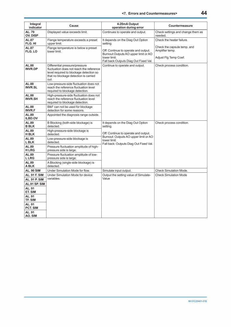
<7. Errors and Countermeasures> 44
IM01C25A01-01E
Integral indicator Cause 4-20mA Output
operation during error Countermeasure
AL. 79 OV. DISP
Displayedvalueexceedslimit. Continuestooperateandoutput. Checksettingsandchangethemasneeded.
AL.87 FLG. HI
Flangetemperatureexceedsapresetupper limit.
ItdependsontheDiagOutOptionsetting.
Off:Continuetooperateandoutput.Burnout:OutputsAOupperlimitorAOlower limit.Fallback:OutputsDiagOutFixedVal.
Checktheheaterfailure.
Checkthecapsuletemp.andAmplifiertemp.
AdjustFlgTempCoef.
AL.87 FLG. LO
Flangetemperatureisbelowapresetlower limit.
AL.88 INVR.DP
Differentialpressure/pressurefluctuationdoesnotreachthereferencelevelrequiredtoblockagedetectionsothatnoblockagedetectioniscarriedout.
Continuetooperateandoutput. Checkprocesscondition.
AL.88 INVR.SL
Low-pressure-sidefluctuationdoesnotreachthereferencefluctuationlevelrequiredtoblockagedetection.
AL.88 INVR.SH
High-pressure-sidefluctuationdoesnotreachthereferencefluctuationlevelrequiredtoblockagedetection.
AL.88 INVR.F
BlkFcannotbeusedforblockagedetection for some reasons.
AL.89 ILBD.OV
Appointedthediagnosisrangeoutside.
AL.89 B BLK
BBlocking(both-sideblockage)isdetected.
ItdependsontheDiagOutOptionsetting.
Off:Continuetooperateandoutput.Burnout:OutputsAOupperlimitorAOlower limit.Fallback:OutputsDiagOutFixedVal.
Checkprocesscondition.
AL.89 H BLK
High-pressure-sideblockageisdetected.
AL.89 L BLK
Low-pressure-sideblockageisdetected.
AL.89 H LRG
Pressurefluctuationamplitudeofhigh-pressure side is large.
AL.89 L LRG
Pressurefluctuationamplitudeoflow-pressure side is large.
AL.89 A BLK
ABlocking(single-sideblockage)isdetected.
AL. 90 SIM UnderSimulationModeforflow. Simulate input output. CheckSimulationMode.AL. 91 F. SIM Under Simulation Mode for device
variables.OutputthesettingvalueofSimulate-Value
CheckSimulationModeAL. 91 P. SIMAL.91 SP. SIMAL. 91 ET. SIMAL. 91 TF. SIMAL. 91 PCT. SIMAL. 91 AO. SIM
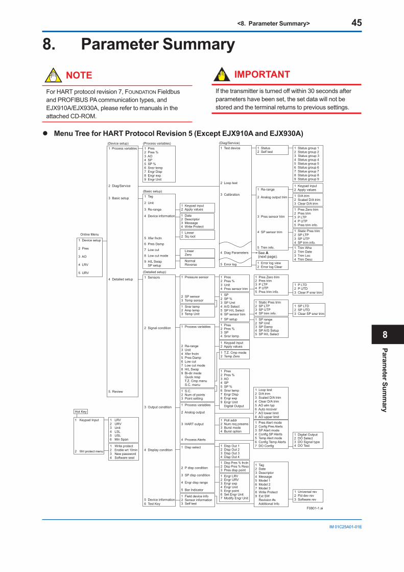
<8. Parameter Summary> 45
IM01C25A01-01E
8. Parameter Summary
NOTEForHARTprotocolrevision7,FOUNDATIONFieldbusandPROFIBUSPAcommunicationtypes,andEJX910A/EJX930A,pleaserefertomanualsintheattachedCD-ROM.
IMPORTANTIfthetransmitteristurnedoffwithin30secondsafterparametershavebeenset,thesetdatawillnotbestoredandtheterminalreturnstoprevioussettings.
Menu Tree for HART Protocol Revision 5 (Except EJX910A and EJX930A)
1 Device setup
2 Pres
3 AO
4 LRV
5 URV
1 Process variables
2 Diag/Service
3 Basic setup
4 Detailed setup
5. Review
1 Pres2 Pres %3 AO4 SP5 SP %6 Snsr temp7 Engr Disp8 Engr exp9 Engr Unit
1 Status group 12 Status group 23 Status group 34 Status group 45 Status group 56 Status group 67 Status group 78 Status group 89 Status group 9
1 Keypad input2 Apply values
1 D/A trim2 Scaled D/A trim3 Clear D/A trim
1 Pres Zero trim2 Pres trim3 P LTP4 P UTP5 Pres trim info.
1 Pres2 Pres %3 SP4 Snsr temp
1 Pres2 Pres %3 Unit4 Pres sensor trim
1 SP2 SP %3 SP Unit4 A/G Select5 SP H/L Select6 SP sensor trim7 SP setup
1 Pres2 Pres %3 AO4 SP5 SP %6 Snsr temp7 Engr Disp8 Engr exp9 Engr Unit Digital Output
1 Loop test2 D/A trim3 Scaled D/A trim4 Clear D/A trim5 AO alm typ6 Auto recover7 AO lower limit8 AO upper limit
1 Poll addr2 Num req preams3 Burst mode4 Burst option
1 Pres Alert mode2 Config Pres Alerts3 SP Alart mode4 Config SP Alerts5 Temp Alert mode6 Config Temp Alerts7 DO Config1 Disp Out 1
2 Disp Out 23 Disp Out 34 Disp Out 4
1 Universal rev2 Fld dev rev3 Software rev
1 S.C.2 Num of points3 Point setting
1 P LTD2 P UTD3 Clear P snsr trim
1 SP LTD2 SP UTD3 Clear SP snsr trim
1 Disp Pres % fnctn2 Disp Pres % Reso3 Pres disp point
1 Engr LRV2 Engr URV3 Engr exp4 Engr Unit5 Engr point6 Set Engr Unit7 Modify Engr Unit
1 Keypad input2 Apply values
1 Date2 Descriptor3 Message4 Write Protect
1 Static Pres trim2 SP LTP3 SP UTP4 SP trim info.1 Trim Who2 Trim Date3 Trim Loc4 Trim Desc
1 Digital Output2 DO Select3 DO Signal type4 DO Test
1 Pres Zero trim2 Pres trim3 P LTP4 P UTP5 Pres trim info.
1 Static Pres trim2 SP LTP3 SP UTP4 SP trim info.
1 T.Z. Cmp mode2 Temp Zero
1 SP range2 SP Unit3 SP Damp4 SP A/G Setup5 SP H/L Select
1 Tag2 Date3 Descriptor4 Message5 Model 16 Model 27 Model 38 Write Protect9 Ext SW Revision #s Additional Info
1 Status2 Self test
1 Re-range
2 Analog output trim
3 Pres sensor trim
4 SP sensor trim
5 Trim info.
1 Error log view2 Error log Clear
1 Process variables
2 Re-range3 Unit4 Xfer fnctn5 Pres Damp6 Low cut7 Low cut mode8 H/L Swap9 Bi-dir mode Quick resp T.Z. Cmp menu S.C. menu
1 Process variables
2 Analog output
3 HART output
4 Process Alerts
1 Disp select
2 P disp condition
3 SP disp condition
4 Engr disp range
5 Bar Indicator
1 Field device info2 Sensor information3 Self test
1 Pressure sensor
2 SP sensor3 Temp sensor
1 Keypad input2 Apply values
1 Linear2 Sq root
Linear Zero
Normal Reverse
1 Snsr temp2 Amp temp3 Temp Unit
1 Test device
2 Loop test
3 Calibration
4 Diag Parameters
5 Error log
Online Menu
(Device setup) (Process variables) (Diag/Service)
1 Tag
2 Unit
3 Re-range
4 Device information
5 Xfer fnctn
6 Pres Damp
7 Low cut
8 Low cut mode
9 H/L Swap SP setup
(Basic setup)
1 Sensors
2 Signal condition
3 Output condition
4 Display condition
5 Device information6 Test Key
(Detailed setup)
1 Keypad Input
2 Wrt protect menu
Hot Key
1 LRV2 URV3 Unit4 LSL5 USL6 Min Span
1 Write protect2 Enable wrt 10min3 New password4 Software seal
F0801-1.ai
See A (next page).
Parameter Sum
mary
8
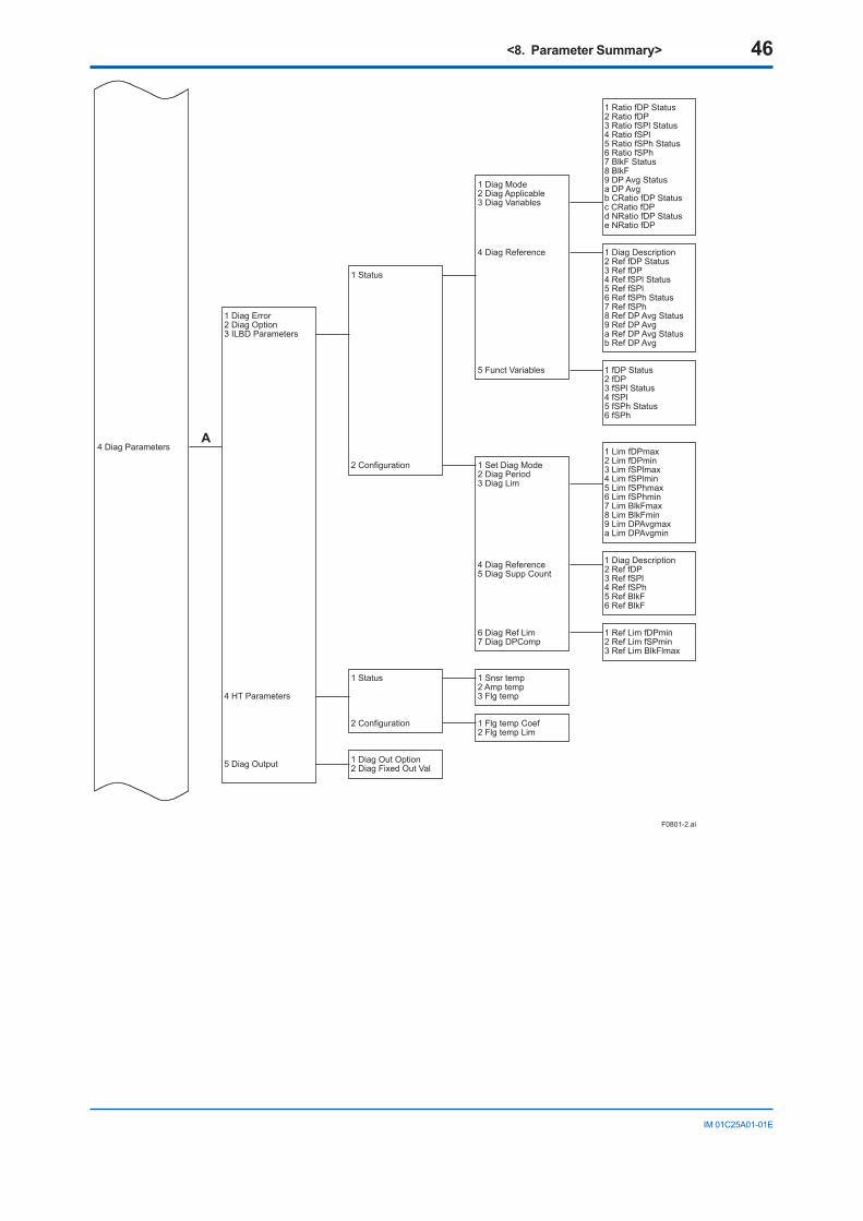
<8. Parameter Summary> 46
IM01C25A01-01E
A
5 Diag Output 1 Diag Out Option2 Diag Fixed Out Val
3 Ref Lim BlkFlmax
1 Set Diag Mode2 Diag Period3 Diag Lim
4 Diag Reference5 Diag Supp Count
6 Diag Ref Lim
5 Ref BlkF6 Ref BlkF
8 Lim BlkFmin9 Lim DPAvgmaxa Lim DPAvgmin
7 Diag DPComp1 Ref Lim fDPmin2 Ref Lim fSPmin
1 Diag Description2 Ref fDP3 Ref fSPl4 Ref fSPh
4 Lim fSPlmin5 Lim fSPhmax6 Lim fSPhmin7 Lim BlkFmax
6 fSPh
1 Lim fDPmax2 Lim fDPmin3 Lim fSPlmax
a Ref DP Avg Statusb Ref DP Avg
1 fDP Status2 fDP
1 Status
2 Configuration
1 Snsr temp2 Amp temp3 Flg temp
1 Flg temp Coef2 Flg temp Lim
4 Ref fSPl Status5 Ref fSPl6 Ref fSPh Status7 Ref fSPh
3 fSPl Status4 fSPl5 fSPh Status
8 Ref DP Avg Status9 Ref DP Avg
e NRatio fDP
4 Ratio fSPl5 Ratio fSPh Status6 Ratio fSPh7 BlkF Status
9 DP Avg Statusa DP Avgb CRatio fDP Statusc CRatio fDPd NRatio fDP Status
2 Configuration
1 Diag Mode
5 Funct Variables
2 Diag Applicable3 Diag Variables
4 Diag Reference
1 Status
1 Ratio fDP Status2 Ratio fDP3 Ratio fSPl Status
8 BlkF
1 Diag Description2 Ref fDP Status3 Ref fDP
1 Diag Error2 Diag Option3 ILBD Parameters
4 Diag Parameters
4 HT Parameters
F0801-2.ai
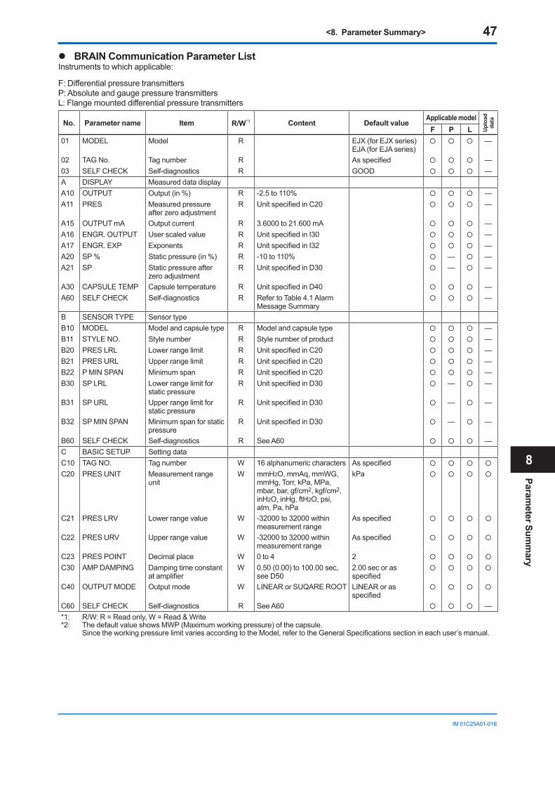
<8. Parameter Summary> 47
IM01C25A01-01E
BRAIN Communication Parameter ListInstrumentstowhichapplicable:
F:DifferentialpressuretransmittersP:AbsoluteandgaugepressuretransmittersL:Flangemounteddifferentialpressuretransmitters
No. Parameter name Item R/W*1 Content Default valueApplicable model
Upl
oad
data
F P L01 MODEL Model R EJX(forEJXseries)
EJA(forEJAseries) —
02 TAGNo. Tagnumber R Asspecified —03 SELFCHECK Self-diagnostics R GOOD —A DISPLAY Measured data displayA10 OUTPUT Output (in %) R -2.5to110% —A11 PRES Measured pressure
afterzeroadjustmentR UnitspecifiedinC20 —
A15 OUTPUT mA Output current R 3.6000 to 21.600 mA —A16 ENGR.OUTPUT User scaled value R UnitspecifiedinI30 —A17 ENGR.EXP Exponents R UnitspecifiedinI32 —A20 SP % Static pressure (in %) R -10to110% — —A21 SP Static pressure after
zeroadjustmentR UnitspecifiedinD30 — —
A30 CAPSULETEMP Capsuletemperature R UnitspecifiedinD40 —A60 SELFCHECK Self-diagnostics R RefertoTable4.1Alarm
Message Summary —
B SENSORTYPE Sensor typeB10 MODEL Model and capsule type R Model and capsule type —B11 STYLENO. Stylenumber R Stylenumberofproduct —B20 PRESLRL Lowerrangelimit R UnitspecifiedinC20 —B21 PRESURL Upper range limit R UnitspecifiedinC20 —B22 PMINSPAN Minimum span R UnitspecifiedinC20 —B30 SPLRL Lowerrangelimitfor
static pressureR UnitspecifiedinD30 — —
B31 SPURL Upper range limit for static pressure
R UnitspecifiedinD30 — —
B32 SPMINSPAN Minimum span for static pressure
R UnitspecifiedinD30 — —
B60 SELFCHECK Self-diagnostics R See A60 —C BASICSETUP Setting dataC10 TAGNO. Tagnumber W 16alphanumericcharacters Asspecified
C20 PRESUNIT Measurement range unit
W mmH2O,mmAq,mmWG,mmHg,Torr,kPa,MPa,mbar,bar,gf/cm2,kgf/cm2,inH2O,inHg,ftH2O,psi,atm,Pa,hPa
kPa
C21 PRESLRV Lowerrangevalue W -32000to32000withinmeasurement range
Asspecified
C22 PRES URV Upper range value W -32000to32000withinmeasurement range
Asspecified
C23 PRESPOINT Decimal place W 0 to 4 2
C30 AMPDAMPING Damping time constant atamplifier
W 0.50(0.00)to100.00sec,see D50
2.00 sec or as specified
C40 OUTPUT MODE Output mode W LINEARorSUQAREROOT LINEARorasspecified
C60 SELFCHECK Self-diagnostics R See A60 —*1: R/W:R=Readonly,W=Read&Write*2: ThedefaultvalueshowsMWP(Maximumworkingpressure)ofthecapsule.
SincetheworkingpressurelimitvariesaccordingtotheModel,refertotheGeneralSpecificationssectionineachuser’smanual.
Parameter Sum
mary
8
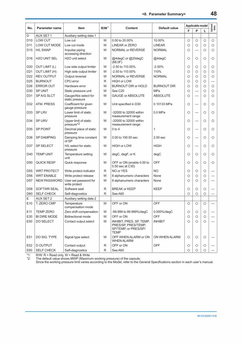
<8. Parameter Summary> 48
IM01C25A01-01E
No. Parameter name Item R/W*1 Content Default valueApplicable model
Upl
oad
data
F P LD AUX SET 1 Auxiliarysettingdata1D10 LOWCUT Lowcut W 0.00 to 20.00% 10.00%
D11 LOWCUTMODE Lowcutmode W LINEARorZERO LINEAR
D15 H/LSWAP Impulsepipingaccessing direction
W NORMALorREVERSE NORMAL —
D16 H2OUNITSEL H2Ounitselect W @4degCor@20degC(68.0F)
@4degC
D20 OUTLIMIT(L) Lowsideoutputlimiter W -2.50to110.00% -2.50%
D21 OUTLIMIT(H) Highsideoutputlimiter W -2.50to110.00% 110%
D22 REV OUTPUT Output reversal W NORMALorREVERSE NORMAL
D25 BURNOUT CPUerror R HIGHorLOW —D26 ERROR OUT Hardwareerror W BURNOUTDIRorHOLD BURNOUTDIR
D30 SPUNIT Static pressure unit W SeeC20 MPa —
D31 SPA/GSLCT Gauge/Absselectforstatic pressure
W GAUGEorABSOLUTE ABSOLUTE —
D32 ATM. PRESS Coefficientforgivengauge pressure
W UnitspecifiedinD30 0.10133 MPa —
D33 SPLRV Lowerlimitofstaticpressure
W -32000to32000withinmeasurement range
0.0 MPa —
D34 SP URV Upper limit of static pressure*2
W -32000to32000withinmeasurement range
—
D35 SPPOINT Decimal place of static pressure
W 0 to 4 1 —
D36 SPDAMPING Damping time constant of SP
W 0.00 to 100.00 sec 2.00 sec —
D37 SPSELECT H/Lselectforstaticpressure
W HIGHorLOW HIGH —
D40 TEMPUNIT Temperature setting unit
W degC,degF,orK degC
D50 QUICKRESP Quickresponse W OFForON(enable0.00to0.50secatC30)
OFF
D55 WRTPROTECT Write protect indicator R NOorYES NO —D56 WRTENABLE Write protect release W 8alphanumericcharacters None —D57 NEWPASSWORD User set password for
write protectW 8alphanumericcharacters None —
D58 SOFTWRSEAL Software seal R BREAKorKEEP KEEP —D60 SELFCHECK Self-diagnostics R See A60 —E AUX SET 2 Auxiliarysettingdata2E10 T.ZEROCMP Temperature
compensation modeW OFForON OFF —
E11 TEMP ZERO Zeroshiftcompensation W -99.999to99.999%/degC 0.000%/degC —E30 BIDIREMODE Bidirectionalmode W OFForON OFF —E50 DOSELECT Contactoutputselect W INHIBIT,PRES,SP,TEMP,
PRES/SP,PRES/TEMP,SP/TEMP,orPRES/SP/TEMP
INHIBIT —
E51 DOSIG.TYPE Signal type select W OFFWHENALARMorONWHENALARM
ONWHENALARM —
E52 D OUTPUT Contactoutput R OFForON OFF —E60 SELFCHECK Self-diagnostics R See A60 —*1: R/W:R=Readonly,W=Read&Write*2: ThedefaultvalueshowsMWP(Maximumworkingpressure)ofthecapsule.
SincetheworkingpressurelimitvariesaccordingtotheModel,refertotheGeneralSpecificationssectionineachuser’smanual.
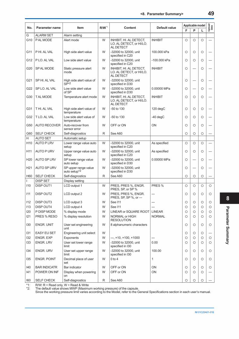
<8. Parameter Summary> 49
IM01C25A01-01E
No. Parameter name Item R/W*1 Content Default valueApplicable model
Upl
oad
data
F P LG ALARMSET Alarm settingG10 PALMODE Alert mode W INHIBIT,HI.ALDETECT,
LO.ALDETECT,orHI/LO.ALDETECT
INHIBIT —
G11 PHI.ALVAL Highsidealertvalue W -32000to32000,unitspecifiedinC20
100.000kPa —
G12 PLO.ALVAL Lowsidealertvalue W -32000to32000,unitspecifiedinC20
-100.000kPa —
G20 SPALMODE Static pressure alert mode
W INHIBIT,HI.ALDETECT,LO.ALDETECT,orHI/LO.ALDETECT
INHIBIT — —
G21 SPHI.ALVAL HighsidealertvalueofSP*2
W -32000to32000,unitspecifiedinD30
— —
G22 SPLO.ALVAL Lowsidealertvalueof SP
W -32000to32000,unitspecifiedinD30
0.00000 MPa — —
G30 TALMODE Temperature alert mode W INHIBIT,HI.ALDETECT,LO.ALDETECT,orHI/LO.ALDETECT
INHIBIT —
G31 THI.ALVAL Highsidealertvalueoftemperature
W -50to130 120degC —
G32 TLO.ALVAL Lowsidealertvalueoftemperature
W -50to130 -40degC —
G50 AUTORECOVER Auto-recoverfromsensor error
W OFForON ON —
G60 SELFCHECK Self-diagnostics R See A60 —H AUTO SET Automatic setupH10 AUTOPLRV Lowerrangevalueauto
setupW -32000to32000,unit
specifiedinC20Asspecified —
H11 AUTO P URV Upper range value auto setup
W -32000to32000,unitspecifiedinC20
Asspecified —
H20 AUTOSPLRV SP lower range value auto setup
W -32000to32000,unitspecifiedinD30
0.00000 MPa — —
H21 AUTO SP URV SP upper range value auto setup*2
W -32000to32000,unitspecifiedinD30
— —
H60 SELFCHECK Self-diagnostics R See A60 —I DISPSET Display settingI10 DISPOUT1 LCDoutput1 W PRES,PRES%,ENGR.
PRES,SP,orSP%PRES %
I11 DISPOUT2 LCDoutput2 W PRES,PRES%,ENGR.PRES,SP,SP%,or---
---
I12 DISPOUT3 LCDoutput3 W SeeI11 ---
I13 DISPOUT4 LCDoutput4 W SeeI11 ---
I20 PDISPMODE % display mode W LINEARorSQUAREROOT LINEAR
I21 PRES % RESO % display resolution W NORMALorHIGHRESOLUTION
NORMAL
I30 ENGR.UNIT User set engineering unit
W 8alphanumericcharacters
I31 EASYEUSET Engineering unit select W —I32 ENGR.EXP Exponents W ---,×10,×100,×1000 ---
I33 ENGR.LRV User set lower range limit
W -32000to32000,unitspecifiedinI30
0.00
I34 ENGR.URV User set upper range limit
W -32000to32000,unitspecifiedinI30
100.00
I35 ENGR.POINT Decimal place of user set
W 0 to 4 1
I40 BARINDICATR Barindicator W OFForON ON
I41 POWERONINF Displaywhenpoweringon
W OFForON ON —
I60 SELFCHECK Self-diagnostics R See A60 —*1: R/W:R=Readonly,W=Read&Write*2: ThedefaultvalueshowsMWP(Maximumworkingpressure)ofthecapsule.
SincetheworkingpressurelimitvariesaccordingtotheModel,refertotheGeneralSpecificationssectionineachuser’smanual.
Parameter Sum
mary
8
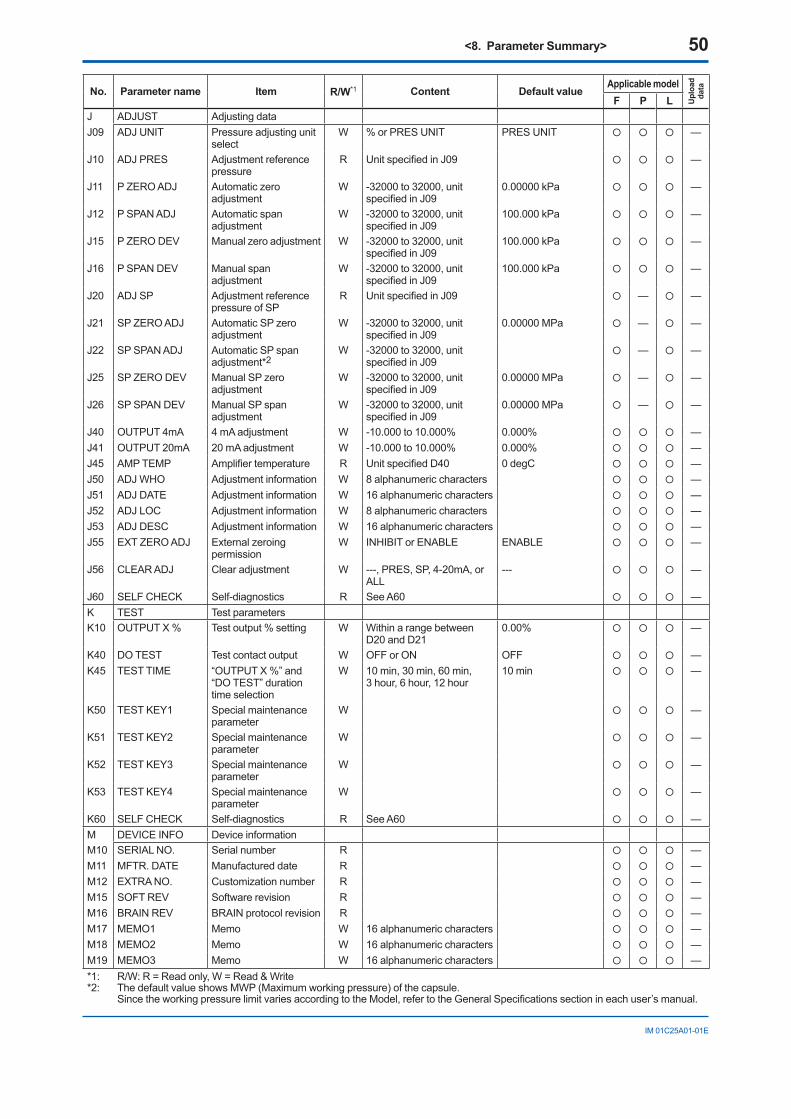
<8. Parameter Summary> 50
IM01C25A01-01E
No. Parameter name Item R/W*1 Content Default valueApplicable model
Upl
oad
data
F P LJ ADJUST Adjusting dataJ09 ADJUNIT Pressure adjusting unit
selectW %orPRESUNIT PRESUNIT —
J10 ADJPRES Adjustment reference pressure
R UnitspecifiedinJ09 —
J11 PZEROADJ Automaticzeroadjustment
W -32000to32000,unitspecifiedinJ09
0.00000kPa —
J12 PSPANADJ Automatic span adjustment
W -32000to32000,unitspecifiedinJ09
100.000kPa —
J15 P ZERO DEV Manualzeroadjustment W -32000to32000,unitspecifiedinJ09
100.000kPa —
J16 PSPANDEV Manual span adjustment
W -32000to32000,unitspecifiedinJ09
100.000kPa —
J20 ADJSP Adjustment reference pressure of SP
R UnitspecifiedinJ09 — —
J21 SPZEROADJ AutomaticSPzeroadjustment
W -32000to32000,unitspecifiedinJ09
0.00000 MPa — —
J22 SPSPANADJ Automatic SP span adjustment*2
W -32000to32000,unitspecifiedinJ09
— —
J25 SP ZERO DEV ManualSPzeroadjustment
W -32000to32000,unitspecifiedinJ09
0.00000 MPa — —
J26 SPSPANDEV Manual SP span adjustment
W -32000to32000,unitspecifiedinJ09
0.00000 MPa — —
J40 OUTPUT 4mA 4 mA adjustment W -10.000to10.000% 0.000% —J41 OUTPUT 20mA 20 mA adjustment W -10.000to10.000% 0.000% —J45 AMP TEMP Amplifiertemperature R UnitspecifiedD40 0degC —J50 ADJWHO Adjustment information W 8alphanumericcharacters —J51 ADJDATE Adjustment information W 16alphanumericcharacters —J52 ADJLOC Adjustment information W 8alphanumericcharacters —J53 ADJDESC Adjustment information W 16alphanumericcharacters —J55 EXTZEROADJ Externalzeroing
permissionW INHIBITorENABLE ENABLE —
J56 CLEARADJ Clearadjustment W ---,PRES,SP,4-20mA,orALL
--- —
J60 SELFCHECK Self-diagnostics R See A60 —K TEST Test parametersK10 OUTPUT X % Test output % setting W Withinarangebetween
D20 and D210.00% —
K40 DO TEST Test contact output W OFForON OFF —K45 TESTTIME “OUTPUTX%”and
“DOTEST”durationtime selection
W 10min,30min,60min, 3hour,6hour,12hour
10 min —
K50 TESTKEY1 Special maintenance parameter
W —
K51 TESTKEY2 Special maintenance parameter
W —
K52 TESTKEY3 Special maintenance parameter
W —
K53 TESTKEY4 Special maintenance parameter
W —
K60 SELFCHECK Self-diagnostics R See A60 —M DEVICEINFO Device informationM10 SERIALNO. Serialnumber R —M11 MFTR. DATE Manufactured date R —M12 EXTRANO. Customizationnumber R —M15 SOFT REV Software revision R —M16 BRAINREV BRAINprotocolrevision R —M17 MEMO1 Memo W 16alphanumericcharacters —M18 MEMO2 Memo W 16alphanumericcharacters —M19 MEMO3 Memo W 16alphanumericcharacters —*1: R/W:R=Readonly,W=Read&Write*2: ThedefaultvalueshowsMWP(Maximumworkingpressure)ofthecapsule.
SincetheworkingpressurelimitvariesaccordingtotheModel,refertotheGeneralSpecificationssectionineachuser’smanual.
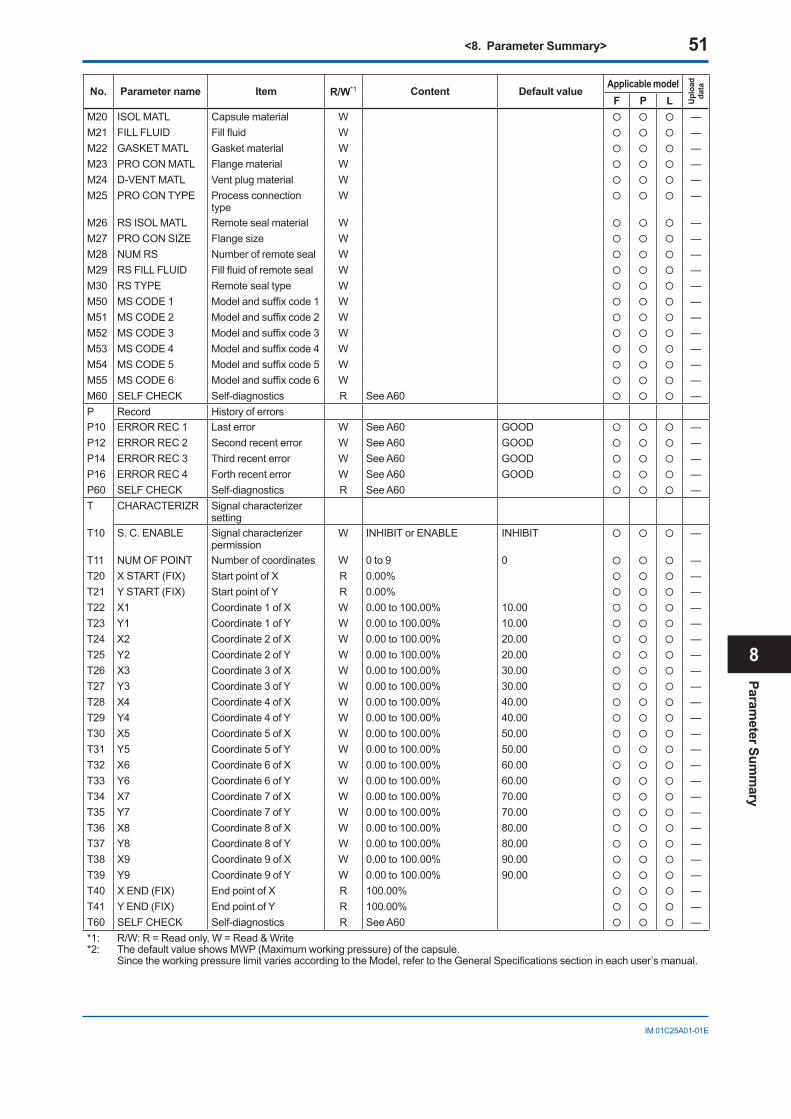
<8. Parameter Summary> 51
IM01C25A01-01E
No. Parameter name Item R/W*1 Content Default valueApplicable model
Upl
oad
data
F P LM20 ISOLMATL Capsulematerial W —M21 FILLFLUID Fillfluid W —M22 GASKETMATL Gasketmaterial W —M23 PROCONMATL Flange material W —M24 D-VENTMATL Vent plug material W —M25 PROCONTYPE Process connection
typeW —
M26 RSISOLMATL Remote seal material W —M27 PROCONSIZE Flangesize W —M28 NUMRS Numberofremoteseal W —M29 RSFILLFLUID Fillfluidofremoteseal W —M30 RSTYPE Remote seal type W —M50 MSCODE1 Modelandsuffixcode1 W —M51 MSCODE2 Modelandsuffixcode2 W —M52 MSCODE3 Modelandsuffixcode3 W —M53 MSCODE4 Modelandsuffixcode4 W —M54 MSCODE5 Modelandsuffixcode5 W —M55 MSCODE6 Modelandsuffixcode6 W —M60 SELFCHECK Self-diagnostics R See A60 —P Record HistoryoferrorsP10 ERRORREC1 Lasterror W See A60 GOOD —P12 ERRORREC2 Second recent error W See A60 GOOD —P14 ERRORREC3 Thirdrecenterror W See A60 GOOD —P16 ERRORREC4 Forthrecenterror W See A60 GOOD —P60 SELFCHECK Self-diagnostics R See A60 —T CHARACTERIZR Signalcharacterizer
settingT10 S.C.ENABLE Signalcharacterizer
permissionW INHIBITorENABLE INHIBIT —
T11 NUMOFPOINT Numberofcoordinates W 0 to 9 0 —T20 XSTART(FIX) Start point of X R 0.00% —T21 YSTART(FIX) StartpointofY R 0.00% —T22 X1 Coordinate1ofX W 0.00 to 100.00% 10.00 —T23 Y1 Coordinate1ofY W 0.00 to 100.00% 10.00 —T24 X2 Coordinate2ofX W 0.00 to 100.00% 20.00 —T25 Y2 Coordinate2ofY W 0.00 to 100.00% 20.00 —T26 X3 Coordinate3ofX W 0.00 to 100.00% 30.00 —T27 Y3 Coordinate3ofY W 0.00 to 100.00% 30.00 —T28 X4 Coordinate4ofX W 0.00 to 100.00% 40.00 —T29 Y4 Coordinate4ofY W 0.00 to 100.00% 40.00 —T30 X5 Coordinate5ofX W 0.00 to 100.00% 50.00 —T31 Y5 Coordinate5ofY W 0.00 to 100.00% 50.00 —T32 X6 Coordinate6ofX W 0.00 to 100.00% 60.00 —T33 Y6 Coordinate6ofY W 0.00 to 100.00% 60.00 —T34 X7 Coordinate7ofX W 0.00 to 100.00% 70.00 —T35 Y7 Coordinate7ofY W 0.00 to 100.00% 70.00 —T36 X8 Coordinate8ofX W 0.00 to 100.00% 80.00 —T37 Y8 Coordinate8ofY W 0.00 to 100.00% 80.00 —T38 X9 Coordinate9ofX W 0.00 to 100.00% 90.00 —T39 Y9 Coordinate9ofY W 0.00 to 100.00% 90.00 —T40 XEND(FIX) End point of X R 100.00% —T41 YEND(FIX) EndpointofY R 100.00% —T60 SELFCHECK Self-diagnostics R See A60 —*1: R/W:R=Readonly,W=Read&Write*2: ThedefaultvalueshowsMWP(Maximumworkingpressure)ofthecapsule.
SincetheworkingpressurelimitvariesaccordingtotheModel,refertotheGeneralSpecificationssectionineachuser’smanual.
Parameter Sum
mary
8
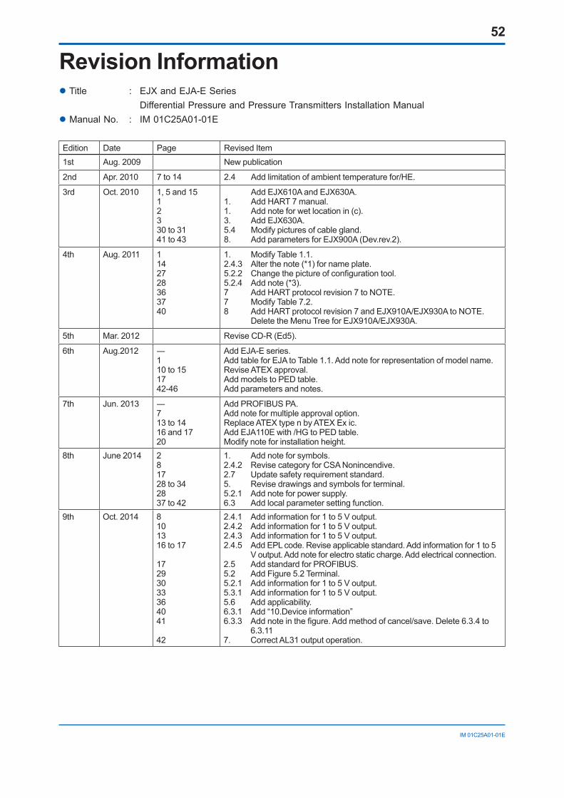
52
IM01C25A01-01E
Revision InformationTitle : EJXandEJA-ESeries DifferentialPressureandPressureTransmittersInstallationManualManualNo. : IM01C25A01-01E
Edition Date Page RevisedItem1st Aug. 2009 Newpublication
2nd Apr. 2010 7 to 14 2.4 Addlimitationofambienttemperaturefor/HE.
3rd Oct. 2010 1,5and1512330 to 3141 to 43
AddEJX610AandEJX630A.1. AddHART7manual.1. Add note for wet location in (c).3. AddEJX630A.5.4 Modifypicturesofcablegland.8. AddparametersforEJX900A(Dev.rev.2).
4th Aug. 2011 1142728363740
1. ModifyTable1.1.2.4.3 Alterthenote(*1)fornameplate.5.2.2 Changethepictureofconfigurationtool.5.2.4 Add note (*3).7 AddHARTprotocolrevision7toNOTE.7 ModifyTable7.2.8 AddHARTprotocolrevision7andEJX910A/EJX930AtoNOTE. DeletetheMenuTreeforEJX910A/EJX930A.
5th Mar. 2012 ReviseCD-R(Ed5).
6th Aug.2012 ―110 to 151742-46
AddEJA-Eseries.AddtableforEJAtoTable1.1.Addnoteforrepresentationofmodelname.Revise ATEX approval.AddmodelstoPEDtable.Add parameters and notes.
7th Jun.2013 ―713 to 1416 and 1720
AddPROFIBUSPA.Add note for multiple approval option.ReplaceATEXtypenbyATEXExic.AddEJA110Ewith/HGtoPEDtable.Modifynoteforinstallationheight.
8th June2014 281728 to 342837 to 42
1. Addnoteforsymbols.2.4.2 RevisecategoryforCSANonincendive.2.7 Update safety requirement standard.5. Revisedrawingsandsymbolsforterminal.5.2.1 Add note for power supply.6.3 Add local parameter setting function.
9th Oct. 2014 8101316 to 17
17293033364041
42
2.4.1 Add information for 1 to 5 V output.2.4.2 Add information for 1 to 5 V output.2.4.3 Add information for 1 to 5 V output.2.4.5 AddEPLcode.Reviseapplicablestandard.Addinformationfor1to5
Voutput.Addnoteforelectrostaticcharge.Addelectricalconnection.2.5 AddstandardforPROFIBUS.5.2 Add Figure 5.2 Terminal. 5.2.1 Add information for 1 to 5 V output.5.3.1 Add information for 1 to 5 V output.5.6 Addapplicability.6.3.1 Add“10.Deviceinformation”6.3.3 Addnoteinthefigure.Addmethodofcancel/save.Delete6.3.4to
6.3.117. CorrectAL31outputoperation.

BlankPage

www.yokogawa.com/fld/
Copyright © 2009 Yokogawa Electric Corporation. All Rights Reserved.
EJX and EJA-E Series Electronic User’s Manual IM 01C25A11-01E
[System Requirements ]
OS : Microsoft Windows 7, Microsoft Windows XP (Professional) CPU : Pentium 300 MHz or higher RAM : 128 MB or more Display : 800 × 600 SVGA or higher, 256 colors
[Contents ]
[Trademarks]
This CD-R contains information in PDF format that is necessary for safe and effective operation of the product.
Microsoft, MS-DOS, Windows and Windows NT are either registered trademarks or trademarks of Microsoft Corporation in the United States and/or other countries.Other company and product names are trademarks or registered trademarks of their respective holders.
WARNING: This CD contains software, and is for use in a computer only. Do not play this on an audio CD player, as the high volume may damage your hearing or audio speakers.
for Windows
Not for sale
YOKOGAWA ELECTRIC CORPORATIONHeadquarters2-9-32, Nakacho, Musashino-shi, Tokyo, 180-8750 JAPANPhone : 81-422-52-5555
Branch Sales OfficesOsaka, Nagoya, Hiroshima, Kurashiki, Fukuoka, Kitakyusyu
YOKOGAWA CORPORATION OF AMERICAHead Office12530 West Airport Blvd, Sugar Land, Texas 77478, USAPhone : 1-281-340-3800 Fax : 1-281-340-3838
Georgia Office2 Dart Road, Newnan, Georgia 30265, USA Phone : 1-800-888-6400/ 1-770-253-7000 Fax : 1-770-254-0928
YOKOGAWA AMERICA DO SUL LTDA.Praca Acapulco, 31 - Santo Amaro, Sáo Paulo/SP, BRAZIL, CEP-04675-190Phone : 55-11-5681-2400 Fax : 55-11-5681-4434
YOKOGAWA EUROPE B. V.Euroweg 2, 3825 HD Amersfoort, THE NETHERLANDSPhone : 31-88-4641000 Fax : 31-88-4641111
YOKOGAWA ELECTRIC CIS LTD.Grokholskiy per 13 Building 2, 4th Floor 129090, Moscow, RUSSIAPhone : 7-495-737-7868 Fax : 7-495-737-7869
YOKOGAWA CHINA CO., LTD.3F Tower D Cartelo Crocodile Building, No.568 West Tianshan Road, Shanghai 200335, CHINAPhone : 86-21-62396262 Fax : 86-21-62387866
YOKOGAWA ELECTRIC KOREA CO., LTD.14-1, Yangpyeongdong-4Ga, Yeongdeungpo-Gu, Seoul,150-866, KOREAPhone : 82-2-2628-6000 Fax : 82-2-2628-6400
YOKOGAWA ENGINEERING ASIA PTE. LTD.5 Bedok South Road, Singapore 469270, SINGAPOREPhone : 65-6241-9933 Fax : 65-6241-2606
YOKOGAWA INDIA LTD.Plot No.96, Electronic City Complex, Hosur Road, Bangalore - 560 100, INDIAPhone : 91-80-4158-6000 Fax : 91-80-2852-1442
YOKOGAWA AUSTRALIA PTY. LTD.Tower A, 112-118 Talavera Road, Macquarie Park NSW 2113, AUSTRALIAPhone : 61-2-8870-1100 Fax : 61-2-8870-1111
YOKOGAWA MIDDLE EAST & AFRICA B.S.C.(C)P.O. Box 10070, Manama, Building 577, Road 2516, Busaiteen 225, Muharraq, BAHRAIN Phone : 973-17-358100 Fax : 973-17-336100
Oct. '13
Printed in Japan


![User’s Manual EJX and EJA-E Series Differential Pressure ... · [EJX series Communication Manual] Models Document No. Style DPharp HART 5/HART 7 Communication Type IM 01C25T01-06EN](https://img.pdfslide.us/doc/110x75/5eda7023b3745412b5715724/useras-manual-ejx-and-eja-e-series-differential-pressure-ejx-series-communication.jpg)