Embed Size (px)
Citation preview
GeneralSpecifications
<<Codes>>
06P01Y01-E-E9th Edition June, 2021 (YK)
Yokogawa Electric Corporationwww.yokogawa.com
Diaphragm Seals with DPharpEJA and EJX SeriesPressure TransmittersGS 06P01Y01-E-E
DIRECT OR REMOTE MOUNT DFS DIAPHRAGM SEALS
STANDARD SPECIFICATIONS
The remote or direct mount DFS diaphragm seals are commonly used when process operating conditions extend beyond the normal operating limits of a pressure transmitter. Especially for dP level applications the use of (2) remote diaphragm seal(s) is the most appropriate and economic way to mount the instrument. Diaphragm seals are produced and mounted on Yokogawa DPHarp EJA and EJX pressure transmitters by Badotherm®. For overall performance of the combination DPHarp+DFS, see: www.basecal.com.
Flange / Body Material*316/316L dual grade Stainless Steel
Seal Process connections*Threaded ½” to 1” NPT , BSP, Metric1/2”/ DN15 to 4”/ DN100 flanged50-250 mm. Extension lengths
Capillary*316SS with 304SS armour; standard316SS with 304SS armour + PVC sleeveID 2mm. / 0,08”ID 1mm. / 0,04”316SS direct mount tube
For services where one or more of the following conditions exist, the use of diaphragm seals is appropriate:
• High temperature processes (up to 600°C.)• Clogging potential• Frequent cleaning requirements• Aggressive processes• Highly viscous processes• Abrasive processes• Sanitary requirements• Possible formation of H+ ions (gold coating)
Flushing*Flush ringsFlush valvesBlind and vent plugs
Flange Standard*ASME B16.5EN1092-1API 6A ISO 10423 - TYPE 6BX
Coatings*Gold 25μ & 40μPFAPTFEECTFE
Ratings*cl. 150-2500PN 10-40069 MPa
Wetted part materials*AISI 316(L) STD.AISI 304LAISI 321Alloy 400Alloy B2Alloy C-276TantalumNickel 201Alloy 625Duplex 2205SuperDuplex 2507
On request:AISI 316L UG25-22-2 LMNAISI 904LAlloy 20Alloy 600Alloy 825Alloy C-22254 SMO (6Mo)Titanium Gr. 1Zirconium 702
For further information on the range of Yokogawa DPharp differential and static pressure transmitters please visit:https://www.yokogawa.com/solutions/products-platforms/field-instruments/pressure-transmitters/
*Note: Not all available options are listed in the model codifications. Please contact your Yokogawa Representative for more information.

2<<Codes>>
All Rights Reserved. Copyright © 2008, Yokogawa Electric Corporation GS 06P01Y01-E-ESubject to change without notice.
Filling fluids
Code Temp limits Description Density @ 25°C Badotherm reference
-F1 -20/+350°C -4/+662°F Silicon Oil 1,07 BSO-42
-F2 -40/+250°C -40/+482°F Fluorinated Oil 1,87 BSO-25
-F3 -50/+200°C -58/+392°F Silicon Oil 0,95 BSO-22
-F4 -15/+225°C +5/+437°F FDA approved 0,92 BSO-40
-F5 -40/+400°C -40/+752°F Silicon Oil 0,93 BSO-02
-F6 -80/+100°C -112/+212°F Fluorinated Oil 1,84 BSO-03
-F7 -10/+315°C +14/+599°F Silicon Oil 1,07 BSO-18
-F8 -40/+315°C -40/+599°F Silicon Oil 1,07 BSO-21
-F9 -80/+120°C -112/+248°F Silicon Oil 0,92 BSO-41
-F0 -20/+420°C -4/+788°F Silicon Oil 1,08 BSO-48
Badotherm Diaphragm Seal (DFS) overview
DFS-BF DFS-BFr DFS-BRF DFS-BC
DFS-EXT DFS-USF DFS-USL-F
DFS-UST DFS-USL-T DFS-PS DFS-SA
DFS-BRC
GENERAL INFORMATION
Jun.15, 2021-00

3<<Codes>>
GS 06P01Y01-E-EAll Rights Reserved. Copyright © 2008, Yokogawa Electric CorporationSubject to change without notice.
CertificatesEach Instrument is standard supplied with following certificates:• 3.1 Material Certificate acc. EN10204• Test Certificate (which includes calibration & a pressure test and vacuum test)• Other certifcates, see options per DFS model
Additional certificates and documents available• DFS-DOC -PMI: Positive Material Identification (external) / lot• DFS-DOC -ITP: Inspection Test Plan / lot• DFS-DOC -2.1: 2.1 Certificate - Declaration of Conformity of the order / lot• DFS-DOC -MDB: Manufacturing Data Book (per copy) / lot• DFS-DOC -IOM: IOM manual diaphragm seals / lot• DFS-DOC -PMS: Project manufacturing schedule (monthly) / lot• DFS-DOC -INS: ½ day Inspection facilitated by Badotherm / lot• DFS-DOC -DWG: Type IV GA drawing• DFS-Q5: 5 Points Test Report Including Transmitter adjustment
dD AP/GP DP (2 sided DFS)
23,5 mm 17,5 bar N/A
32 mm 11 bar N/A
44 mm 1575 mbar 255 mbar
50 mm 1000 mbar 180 mbar
57 mm 415 mbar 70 mbar
72 mm 155 mbar 30 mbar
81 mm 110 mbar 20 mbar
Recommended minimum spans per diaphragm diameter (dD, see codification) for: ≤ 3 m. capillary; -F3 (BSO-22) fill fluid; ambient temperature: -10/+40°C; process temperature: ≤ 100°C.
For full technical compatibility see: http://www.basecal.com/
For all detailed data sheets and dimensions, see: http://www.badotherm.com/downloads.html
Jun.15, 2021-00

4<<Codes>>
All Rights Reserved. Copyright © 2008, Yokogawa Electric Corporation GS 06P01Y01-E-ESubject to change without notice.
Direct Mount EJA/EJX-110/430 Direct Mount EJA/EJX-530 Welded / Full welded
Remote Mount EJA/EJX-530 Welded / Full Welded Remote Mount EJA/EJX-110/430 - Single seal
ASSEMBLY DRAWINGS
Jun.15, 2021-00
Direct mount: maximum process temperature: 175°CDirect mount + /DM1: maximum process temperature: 225°CDirect mount + /DM2: maximum process temperature: 300°CDirect mount + /TR: maximum process temperature: 420°C
Direct mount: maximum process temperature: 225°CDirect mount + /DM2: maximum process temperature: 300°CDirect mount + /TR: maximum process temperature: 420°C

5<<Codes>>
GS 06P01Y01-E-EAll Rights Reserved. Copyright © 2008, Yokogawa Electric CorporationSubject to change without notice.
Remote Mount EJA/EJX-110 - 2 seals Remote Mount EJA/EJX-110 - 2 sealsFull welded construction
Direct Mount + Remote mount EJA/EJX - 110Remote Mount EJA/EJX-110/430 - Single sealFull welded construction
Direct mount: maximum process temperature: 225°CDirect mount + /DM2: maximum process temperature: 300°CDirect mount + /TR: maximum process temperature: 420°C
Direct mount: maximum process temperature: 225°CDirect mount + /DM2: maximum process temperature: 300°CDirect mount + /TR: maximum process temperature: 420°C
Direct mount flanged process connection (FPC). Welded construction
Jun.15, 2021-00

6<<Codes>>
All Rights Reserved. Copyright © 2008, Yokogawa Electric Corporation GS 06P01Y01-E-ESubject to change without notice.
6
• DFS-BF Diaphragm Seal - Blind flange, Raised Face.................................................7
• DFS-BFr Diaphragm Seal - Blind flange, Ring Joint Facing......................................11
• DFS-BRF Diaphragm Seal - Blind flange, Raised Face............................................15
• DFS-BC Diaphragm Seal - Blind flange, Raised Face..............................................19
• DFS-BRC Diaphragm Seal - Blind flange, Raised Face............................................22
• DFS-EXT Diaphragm Seal - Extended, Flush Diaphragm, Flanged type...................26
• DFS-USF Diaphragm Seal - Internal Diaphragm, Flanged type.................................29
• DFS-USL-F Diaphragm Seal - Internal Diaphragm, Flanged type.............................34
• DFS-UST Diaphragm Seal - Internal Diaphragm Threaded........................................39
• DFS-USL-T Diaphragm Seal - Internal Diaphragm, Threaded...................................44
• DFS-PS Diaphragm Seal - Plug Seal.........................................................................49
• DFS-SA Diaphragm Seal - Sanitary Seals.................................................................50
• Open FPC....................................................................................................................53
MODEL AND SUFFIX CODES
Jun.15, 2021-00

7<<Codes>>
GS 06P01Y01-E-EAll Rights Reserved. Copyright © 2008, Yokogawa Electric CorporationSubject to change without notice.
7
1. DFS-BF Diaphragm Seal - Blind flange, Raised Face
1.1. Model
1.3. Mounting
1.2. Seal Type
TXCP EJA-E / EJX-A 130 & 440Series
TXCM EJA-E / EJX-A 100, 300 & 400 SeriesTXCD EJA-E / EJX-A 500 & 600 Series (preferred connection “4” / WN)
WN5 TXCM with W option =/N5 mandatory option
XN5 TXCD no N5 / W available
DFS-BF Diaphragm Seal - Blind flange, Raised Face
1.4. Flange Size & RatingdD (min. span, see page 3)
02A1 1" cl. 150 RF acc. ASME B16.5 23,5 mm.02A2 1" cl. 300 RF acc. ASME B16.5 23,5 mm.02A4 1" cl. 600 RF acc. ASME B16.5 23,5 mm.02A6 1” cl. 1500 RF acc. ASME B16.5 23,5 mm.02A7 1” cl. 2500 RF acc. ASME B16.5 23,5 mm.04A1 1,5” cl. 150 RF acc. ASME B16.5 44 mm.04A2 1,5” cl. 300 RF acc. ASME B16.5 44 mm.04A4 1,5” cl. 600 RF acc. ASME B16.5 44 mm.04A6 1,5” cl. 1500 RF acc. ASME B16.5 32 mm.04A7 1,5” cl. 2500 RF acc. ASME B16.5 32 mm.05A1 2” cl. 150 RF acc. ASME B16.5 57 mm.
05A2 2” cl. 300 RF acc. ASME B16.5 57 mm.05A4 2” cl. 600 RF acc. ASME B16.5 57 mm.05A6 2” cl. 1500 RF acc. ASME B16.5 44 mm.05A7 2” cl. 2500 RF acc. ASME B16.5 44 mm.08A1 3” cl. 150 RF acc. ASME B16.5 81 mm.08A2 3” cl. 300 RF acc. ASME B16.5 81 mm.08A4 3” cl. 600 RF acc. ASME B16.5 81 mm.08A5 3” cl. 900 RF acc. ASME B16.5 81 mm.08A6 3" cl. 1500 RF acc. ASME B16.5 81 mm.08A7 3” cl. 2500 RF acc. ASME B16.5 81 mm.10A1 4” cl. 150 RF acc. ASME B16.5 81 mm.10A2 4” cl. 300 RF acc. ASME B16.5 81 mm.02D4 DN25 PN10-40 form B1 acc. EN 1092-1 32 mm.02D5 DN25 PN63 form B1 acc. EN 1092-1 32 mm.02D6 DN25 PN100 form B1 acc. EN 1092-1 32 mm.04D4 DN40 PN10-40 form B1 acc. EN 1092-1 44 mm.05D4 DN50 PN10-40 form B1 acc. EN 1092-1 57 mm.05D5 DN50 PN63 form B1 acc. EN 1092-1 57 mm.08D4 DN80 PN10-40 form B1 acc. EN 1092-1 81 mm.10D2 DN100 PN10-16 form B1 acc. EN 1092-1 81 mm.10D4 DN100 PN25-40 form B1 acc. EN 1092-1 81 mm.
Jun.15, 2021-00
8<<Codes>>
All Rights Reserved. Copyright © 2008, Yokogawa Electric Corporation GS 06P01Y01-E-ESubject to change without notice.
8
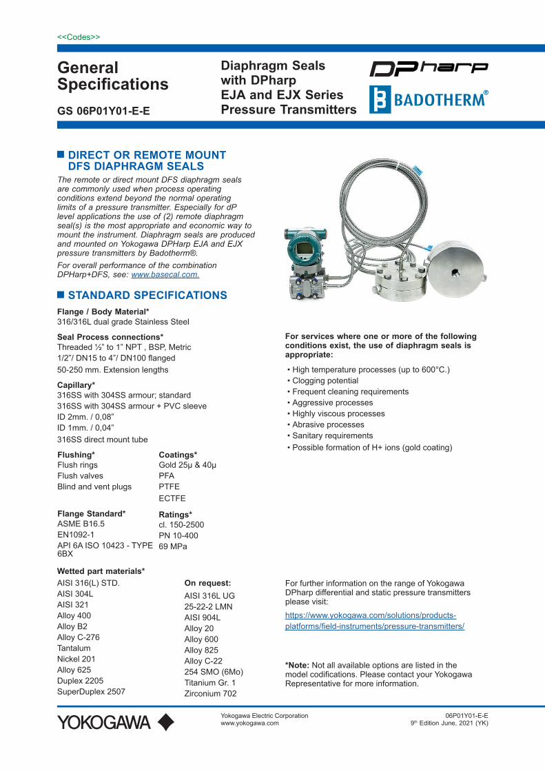
1.5. Flange MaterialSS SS AISI 316(L)
1.6. Diaphragm MaterialSS SS AISI 316(L)HC Alloy C276A1 25 μm gold (24 Crt) size 05 (on diaphragm)A2 40 μm gold (24 Crt) size 05 (on wetted parts)
A3 25 μm gold (24 Crt) size 08 (on diaphragm)A4 40 μm gold (24 Crt) size 08 (on wetted parts)PF Coating PFA (+/- 40 µm thickness) - (anti-stick only)PT Coating PTFE (+/- 35 µm thickness) - (anti-stick only)
1.7. Fill Fluid-F1 BSO-42 Silicon Oil -20/+350°C -4/+662°F
-F2 BSO-25 Fluorinated O -40/+250°C -40/+482°F
-F3 BSO-22 Silicon Oil -50/+200°C -58/+392°F
-F4 BSO-40 FDA approved -15/+225°C +5/+437°F
-F5 BSO-02 Silicon Oil -40/+400°C -40/+752°F
-F6 BSO-03 Fluorinated Oil 80/+100°C -112/+212°F
-F7 BSO-18 Silicon Oil -10/+315°C +14/+599°F
-F8 BSO-21 Silicon Oil -40/+315°C -40/+599°F
-F9 BSO-41 Silicon Oil -80/+120°C -112/+248°F
-F0 BSO-48 Silicon Oil -20/+420°C -4/+788°F
1.8. Capillary Size / Type (AISI 316 Stainless Steel Armoured)NN Direct coupled / Welded (No Capillary)
C1 Capillary (2mm ID) - Axial
C2 Capillary (2mm ID) - Radial
1.9. Capillary LengthNN Direct coupled / Welded (No Capillary)
01 1 m 3 ft.
1A 1,5 m 5ft.
02 2 m 6 ft.
03 3 m 10 ft
04 4 m 13 ft.
05 5 m 15 ft.
06 6 m 20 ft
07 7 m 23 ft.
08 8 m 25 ft.
09 9 m 30 ft.
10 10 m 33 ft.
11 11m 35 ft.
12 12 m 40 ft.
13 13 m 43 ft
14 14 m 45 ft.
15 15 m 50 ft.
Jun.15, 2021-00

9<<Codes>>
GS 06P01Y01-E-EAll Rights Reserved. Copyright © 2008, Yokogawa Electric CorporationSubject to change without notice.
9
1.10. Flush rings in AISI 316(L)/FL01 size 02 RF/B1 Mat. 316(L); unplugged 1 x 1/4” NPT/FL02 size 02 RF/B1 Mat. 316(L); unplugged 1 x 1/2” NPT/FL03 size 04 RF/B1 Mat. 316(L); unplugged 1 x 1/4” NPT/FL04 size 04 RF/B1 Mat. 316(L); unplugged 1 x 1/2” NPT/FL05 size 05 RF/B1 Mat. 316(L); unplugged 1 x 1/4” NPT/FL06 size 05 RF/B1 Mat. 316(L); unplugged 1 x 1/2” NPT/FL07 size 08 RF/B1 Mat. 316(L); unplugged 1 x 1/4” NPT/FL08 size 08 RF/B1 Mat. 316(L); unplugged 1 x 1/2” NPT/FL09 size 10 RF/B1 Mat. 316(L); unplugged 1 x 1/4” NPT/FL10 size 10 RF/B1 Mat. 316(L); unplugged 1 x 1/2” NPT/F21 Second flush port 1/4” NPTf/F22 Second flush port 1/2” NPTf
/FLV1 Vent plugs 1/4”/FLV2 Vent plugs 1/2”/FLP1 Blind plugs 1/4”/FLP2 Blind plugs 1/2”/FV91 Pair flush valves BDTV911 for 1/4” ports (fitted)/FV92 Pair flush valves BDTV911 for 1/2" ports (fitted)/FV93 Single flush valve BDTV911 for 1/4" port (fitted)/FV94 Single flush valve BDTV911 for 1/2” port (fitted)
1.11. Options/N5 EJX/EJA100/300/400 + W option Low volume covers by Yokogawa/FW Full welded construction recomm. for vacuum service (< 500 mbara)
/FWS Full Welded construction for 500/600 series recomm. for vacuum service (< 500 mbara)/DM1 Extended Direct mount (80mm) (temp reduction: 100°C)
/DM2 Extended Direct mount (150 mm) (temp reduction: 175°C)/TR Temperature reducer (max. temp. fill fluid allowed)/IC1 Capillary ID 1 mm. / 0,04”/BS6 Black sleeve on capillary ≤ 6 m.
/BS15 Black sleeve on capillary > 6 ≤ 15 m./LH Lifting handles (recomm.for ≥ cl. 900)/K1 Degreasing Treatment I + certificate/K2 Degreasing Treatment (applicable F2 fill) + certificate
/NACE NACE MR01-75 (ISO15156) or MR0103 (ISO17945) compliance/BAS Basecal performance calculation report/DP1 Dye penetrant test pressurized welds + 2.2 EN-10204 test report (Level I)/DP2 Dye penetrant test pressurized welds + 3.1 EN-10204 test report (Level II)
/QDBDT <5 working days ex works BADO or rush charge compensation
Jun.15, 2021-00

10<<Codes>>
All Rights Reserved. Copyright © 2008, Yokogawa Electric Corporation GS 06P01Y01-E-ESubject to change without notice.
10
ASME 16.5 RF facingSize Rating OD b PCD C / pcs dD R f G Weight
1”
cl. 150 110.0 14,7 79.4 15.9 / 4x
23.5 50.8
2.0
31.8
0.9
cl. 300
125.0
17,988.9 19.1 / 4x
1.4
cl. 400-600 24.5 1.6
cl. 900-1500 150.0 35.6 101.625.4 / 4x 7.0
3.6
cl. 2500 160.0 42.0 108.0 5.0
1.5”
cl. 150 125.0 17.9 98.4 15.9 / 4x44.0
73.0
2.0
52.4
1.5
cl. 300155.0
21.1114.3 22.3 / 4x
2.7
cl. 400-600 29.37.0
3.3
cl. 900-1500 180.0 38.8 123.8 28.6 / 4x32.0 41.5
5.8
cl. 2500 205.0 51.5 146.0 31.8 / 4x 10.4
2”
cl. 150 150.0 19.5 120.7 19.1 / 4x
57.0
92.1
2.070.2
2.4
cl. 300165.0
22.7127.0 19.1 / 8x
3.2
cl. 400-600 32.47.0
4.2
cl. 900-1500 215.0 45.1 165.1 25.4 / 8x 44.055.4
10.1
cl. 2500 235.0 57.9 171.4 28.6 / 8x 15.6
3”
cl. 150 190.0 24.3 152.4 19.1 / 4x
81.0
127.02.0
93.0
4.9
cl. 300210.0
29.0168.3 22.3 / 8x
6.8
cl. 400-600 38.8
7.0
8.4
cl. 900 240.0 45.1 190.5 25.4 / 8x 13.1
cl. 1500 265.0 54.7 203.2 31.9 / 8x 19.1
cl. 2500 305.0 73.7 228.6 35.0 / 8x 34.8
4”cl. 150 230.0 24.3 190.5 19.1 / 8x
81.0 157.2 2.0 93.07.0
cl. 300 255.0 32.2 200.0 22.3 / 8x 11.5
EN 1092-1 type B1Size Rating OD b PCD C / pcs dD R f G Weight
DN25PN10-40 115.0 18.0 85.0 14.0 / 4x
32.0 68.0 2.0 41.01.0
PN63-100 140.0 24.0 100.0 18.0 / 4x 2.5
DN40 PN10-40 150.0 18.0 110.0 18.0 / 4x 44.0 88.0
3.0
55.4 2.0
DN50 PN10-40 165.0 20.0 125.0 18.0 / 4x 57.0 102.0 70.2 3.0
DN80 PN10-40 215.0 24.0 160.0 18.0 / 8x
81.0
138.0
93.0
5.0
DN100PN10-16 220.0 20.0 180.0 18.0 / 8x 158.0 4.5
PN25-40 235.0 24.0 190.0 22.0 / 8x 162.0 6.5
All dimensions in mm, weight in kg.
Flush ring dimensions, see page 25
Jun.15, 2021-00
Dimensions tables

11<<Codes>>
GS 06P01Y01-E-EAll Rights Reserved. Copyright © 2008, Yokogawa Electric CorporationSubject to change without notice.
11
2. DFS-BFr Diaphragm Seal - Blind flange, Ring Joint Facing
2.4. Flange Size & RatingdD (min. span, see page 3)
05A1 2” cl. 150 RF acc. ASME B16.5 57 mm.
05A2 2” cl. 300 RF acc. ASME B16.5 57 mm.05A4 2” cl. 600 RF acc. ASME B16.5 57 mm.05A6 2” cl. 1500 RF acc. ASME B16.5 57 mm.05A7 2” cl. 2500 RF acc. ASME B16.5 57 mm.08A1 3” cl. 150 RF acc. ASME B16.5 81 mm.08A2 3” cl. 300 RF acc. ASME B16.5 81 mm.08A4 3” cl. 600 RF acc. ASME B16.5 81 mm.08A5 3” cl. 900 RJF acc. ASME B16.5 81 mm.08A6 3” cl. 1500 RJF acc. ASME B16.5 81 mm.08A7 3” cl. 2500 RJF acc. ASME B16.5 81 mm.
1669 1-13/16” 6BX 69MPa (10kPSI) acc.API 6A ISO 10423 - TYPE 6BX 32 mm.2669 2-1/16” 6BX 69MPa (10kPSI) acc.API 6A ISO 10423 - TYPE 6BX 44 mm.
2.5. Flange MaterialSS SS AISI 316(L)
2.6. Diaphragm MaterialSS SS AISI 316(L)HC Alloy C276
A1 25 μm gold (24 Crt) size 05 (on diaphragm)A2 40 μm gold (24 Crt) size 05 (on wetted parts)A3 25 μm gold (24 Crt) size 08 (on diaphragm)A4 40 μm gold (24 Crt) size 08 (on wetted parts)PF Coating PFA (+/- 40 μm thickness) - (anti-stick only)PT Coating PTFE (+/- 35 μm thickness) - (anti-stick only)
2.7. Fill Fluid-F1 BSO-42 Silicon Oil -20/+350°C -4/+662°F
-F2 BSO-25 Fluorinated Oil -40/+250°C -40/+482°F-F4 BSO-40 FDA approved -15/+225°C +5/+437°F-F5 BSO-02 Silicon Oil -40/+400°C -40/+752°F-F6 BSO-03 Fluorinated Oil -80/+100°C -112/+212°F
-F7 BSO-18 Silicon Oil -10/+315°C +14/+599°F-F8 BSO-21 Silicon Oil -40/+315°C -40/+599°F
2.1. Model
2.3. Mounting
2.2. Seal Type
TXCM EJA-E / EJX-A 100, 300 & 400 Series
TXCP EJA-E / EJX-A 130 & 440 Series
TXCD EJA-E / EJX-A 500 & 600 Series (preferred connection “4” / WN)
WN5 TXCM with W option =/N5 mandatory option
XN5 TXCD no N5 / W available
DFS-BFr Diaphragm Seal - Blind flange, Ring Joint Facing
Jun.15, 2021-00

12<<Codes>>
All Rights Reserved. Copyright © 2008, Yokogawa Electric Corporation GS 06P01Y01-E-ESubject to change without notice.
12
2.7. Fill Fluid-F9 BSO-41 Silicon Oil -80/+120°C -112/+248°F
-F0 BSO-48 Silicon Oil -20/+420°C -4/+788°F
2.8. Capillary Size / Type (AISI 316 Stainless Steel Armoured)NN Direct coupled / Welded (No Capillary)
C1 Capillary (2mm ID) - axial
C2 Capillary (2mm ID) - radial
2.9. Capillary LengthNN Direct coupled / Welded (No Capillary)
01 1 m 3 ft.
1A 1,5 m 5ft.
02 2 m 6 ft.
03 3 m 10 ft
04 4 m 13 ft.
05 5 m 15 ft.
06 6 m 20 ft
07 7 m 23 ft.
08 8 m 25 ft.
09 9 m 30 ft.
10 10 m 33 ft.
11 11m 35 ft.
12 12 m 40 ft.
13 13 m 43 ft
14 14 m 45 ft.
15 15 m 50 ft.
2.10. Flush rings in AISI 316(L)/FL5A1 2” cl. 150 RJF Mat, 316(L) 1 x 1/4” NPT; unplugged/FL5A2 2” cl. 300 RJF Mat, 316(L) 1 x 1/4” NPT; unplugged
/FL5A4 2” cl. 600 RJF Mat, 316(L) 1 x 1/4” NPT; unplugged/FL5A6 2” cl. 1500 RJF Mat, 316(L) 1 x 1/4” NPT; unplugged/FL5A7 2” cl. 2500 RJF Mat, 316(L) 1 x 1/4” NPT; unplugged/FL8A1 3” cl. 150 RJF Mat, 316(L) 1 x 1/4” NPT; unplugged/FL8A2 3” cl. 300 RJF Mat, 316(L) 1 x 1/4” NPT; unplugged/FL8A4 3” cl. 600 RJF Mat, 316(L) 1 x 1/4” NPT; unplugged
/FL8A5 3” cl. 900 RJF Mat, 316(L) 1 x 1/4” NPT; unplugged
/FL8A6 3” cl. 1500 RJF Mat, 316(L) 1 x 1/4” NPT; unplugged
/FL8A7 3” cl. 2500 RJF Mat, 316(L) 1 x 1/4” NPT; unplugged
/FL169 1-13/16” 6BX 69MPa (10kPSI) Mat, 316(L) 1 x 1/4” NPT; unplugged
/FL269 2-1/16” 6BX 69MPa (10kPSI) Mat, 316(L) 1 x 1/4” NPT; unplugged
/F20 Flush port 1 x 1/2” NPTf
/F21 Second flush port 1/4” NPTf
/F22 Second flush port 1/2” NPTf
/FLV1 Vent plugs 1/4”
/FLV2 Vent plugs 1/2”/FLP1 Blind plugs 1/4”/FLP2 Blind plugs 1/2”
Jun.15, 2021-00

13<<Codes>>
GS 06P01Y01-E-EAll Rights Reserved. Copyright © 2008, Yokogawa Electric CorporationSubject to change without notice.
13
2.10. Flush rings in AISI 316(L)/FV91 Pair flush valves BDTV911 for 1/4” ports (fitted)/FV92 Pair flush valves BDTV911 for 1/2” ports (fitted)/FV93 Single flush valve BDTV911 for 1/4” port (fitted)/FV94 Single flush valve BDTV911 for 1/2” port (fitted)
2.11. Options/N5 EJX/EJA100/300/400 + W option Low volume covers by Yokogawa
/FW Full welded construction recomm. for vacuum service (< 500 mbara)/FWS Full Welded construction for 500/600 series recomm. for vacuum service (< 500 mbara)/DM1 Extended Direct mount (80mm) (temp reduction: 100°C)
/DM2 Extended Direct mount (150 mm) (temp reduction: 175°C)/TR Temperature reducer (max. temp. fill fluid allowed)/IC1 Capillary ID 1 mm. / 0,04”/BS6 Black sleeve on capillary ≤ 6 m.
/BS15 Black sleeve on capillary > 6 ≤ 15 m./LH Lifting handles (recomm.for ≥ cl. 900)/K1 Degreasing Treatment I + certificate/K2 Degreasing Treatment (applicable F2 fill) + certificate
/NACE NACE MR01-75 (ISO15156) or MR0103 (ISO17945) compliance
/BAS Basecal performance calculation report/DP1 Dye penetrant test pressurized welds + 2.2 EN-10204 test report (Level I)/DP2 Dye penetrant test pressurized welds + 3.1 EN-10204 test report (Level II)
/QDBDT <5 working days ex works BADO or rush charge compensation
Jun.15, 2021-00

14<<Codes>>
All Rights Reserved. Copyright © 2008, Yokogawa Electric Corporation GS 06P01Y01-E-ESubject to change without notice.
14
Jun.15, 2021-00
ASME 16.5 RF facingSize Rating OD b PCD C / pcs dD K E F P Ring # Weight
2”
cl. 150 150.0 23.9 120.719.1 / 8x
57.0
102.0 6.4 8.782.6
22 2.4
cl. 300165.0
28.6127.0 108.0
7.9
11.923
3.2
cl. 400-600 33.3 19.1 / 8x 95.3 4.2
cl. 900-1500 215.0 46.0 165.1 25.4 / 8x 124.0 101.6 24 10.1
cl. 2500 235.0 58.8 171.4 28.6 / 8x133.0
114.3 26 15.6
3”
cl. 150 190.0 28.7 152.4 19.1 / 4x
81.0
6.4 8.7 114.3 29 4.9
cl. 300210.0
34.9 168.322.3 / 8x 146.0
7.9 11.9123.8 31
6.8
cl. 400-600 39.7 168.3 8.4
cl. 900 240.0 46.0 190.5 25.4 / 8x 156.0 13.1
cl. 1500 265.0 58.8 203.2 31.8 / 8x168.0
136.5 35 19.1
cl. 2500 305.0 76.2 228.6 34.9 / 8x 9.5 13.5 127.0 32 34.8
API 10423 – Type 6BXSize Rating OD b PCD C / pcs dD K E F RING Weight
1-13/16” 69MPa 185.0 42.1 146.1 23.0 / 8x 32.0 105.0 5.6 77.7 BX-151 9.0
2-1/16” 69MPa 200.0 44.1 158.8 23.0 / 8x 44.0 111.0 5.9 86.2 BX-152 11.0
All dimensions in mm, weight in kg.
Flush ring dimensions, see page 25
Dimensions tables

15<<Codes>>
GS 06P01Y01-E-EAll Rights Reserved. Copyright © 2008, Yokogawa Electric CorporationSubject to change without notice.
15
3. DFS-BRF Diaphragm Seal - Blind flange, Raised Face
3.4. Flange Size & RatingdD (min. span, see page 3)
02A1 1" cl. 150 RF acc. ASME B16.5 23,5 mm.02A2 1" cl. 300 RF acc. ASME B16.5 23,5 mm.02A4 1" cl. 600 RF acc. ASME B16.5 23,5 mm.02A6 1” cl. 1500 RF acc. ASME B16.5 23,5 mm.02A7 1” cl. 2500 RF acc. ASME B16.5 23,5 mm.04A1 1,5” cl. 150 RF acc. ASME B16.5 44 mm.04A2 1,5” cl. 300 RF acc. ASME B16.5 44 mm.04A4 1,5” cl. 600 RF acc. ASME B16.5 44 mm.04A6 1,5” cl. 1500 RF acc. ASME B16.5 32 mm.04A7 1,5” cl. 2500 RF acc. ASME B16.5 32 mm.05A1 2” cl. 150 RF acc. ASME B16.5 57 mm.
05A2 2” cl. 300 RF acc. ASME B16.5 57 mm.05A4 2” cl. 600 RF acc. ASME B16.5 57 mm.05A6 2” cl. 1500 RF acc. ASME B16.5 44 mm.05A7 2” cl. 2500 RF acc. ASME B16.5 44 mm.08A1 3” cl. 150 RF acc. ASME B16.5 81 mm.08A2 3” cl. 300 RF acc. ASME B16.5 81 mm.08A4 3” cl. 600 RF acc. ASME B16.5 81 mm.08A5 3” cl. 900 RF acc. ASME B16.5 81 mm.08A6 3" cl. 1500 RF acc. ASME B16.5 81 mm.08A7 3” cl. 2500 RF acc. ASME B16.5 81 mm.10A1 4” cl. 150 RF acc. ASME B16.5 81 mm.10A2 4” cl. 300 RF acc. ASME B16.5 81 mm.02D4 DN25 PN10-40 form B1 acc. EN 1092-1 32 mm.02D5 DN25 PN63 form B1 acc. EN 1092-1 32 mm.02D6 DN25 PN100 form B1 acc. EN 1092-1 32 mm.04D4 DN40 PN10-40 form B1 acc. EN 1092-1 44 mm.05D4 DN50 PN10-40 form B1 acc. EN 1092-1 57 mm.05D5 DN50 PN63 form B1 acc. EN 1092-1 57 mm.08D4 DN80 PN10-40 form B1 acc. EN 1092-1 81 mm.10D2 DN100 PN10-16 form B1 acc. EN 1092-1 81 mm.10D4 DN100 PN25-40 form B1 acc. EN 1092-1 81 mm.
3.1. Model
3.3. Mounting
3.2. Seal Type
TXCM EJA-E / EJX-A 100, 300 & 400 Series
TXCP EJA-E / EJX-A 130 & 440 Series
TXCD EJA-E / EJX-A 500 & 600 Series (preferred connection “4” / WN)
WN5 TXCM with W option =/N5 mandatory option
XN5 TXCD no N5 / W available
DFS-BRF Diaphragm Seal - Blind flange, Raised Face
Jun.15, 2021-00

16<<Codes>>
All Rights Reserved. Copyright © 2008, Yokogawa Electric Corporation GS 06P01Y01-E-ESubject to change without notice.
16
3.5. Flange MaterialSS SS AISI 316(L)
3.6. Wetted parts material (Diaphragm Material & Raised face covered)HB Alloy B2HC Alloy C276
I6 Alloy 625DU Duplex 2205
SD Super Duplex 2507M4 Alloy 400N2 Nickel 201
TA TantalumS4 AISI304LS2 AISI321
3.7. Fill Fluid-F1 BSO-42 Silicon Oil -20/+350°C -4/+662°F
-F2 BSO-25 Fluorinated O -40/+250°C -40/+482°F
-F3 BSO-22 Silicon Oil -50/+200°C -58/+392°F
-F4 BSO-40 FDA approved -15/+225°C +5/+437°F
-F5 BSO-02 Silicon Oil -40/+400°C -40/+752°F
-F6 BSO-03 Fluorinated Oil 80/+100°C -112/+212°F
-F7 BSO-18 Silicon Oil -10/+315°C +14/+599°F
-F8 BSO-21 Silicon Oil -40/+315°C -40/+599°F
-F9 BSO-41 Silicon Oil -80/+120°C -112/+248°F
-F0 BSO-48 Silicon Oil -20/+420°C -4/+788°F
3.8. Capillary Size / Type (AISI 316 Stainless Steel Armoured)NN Direct coupled / Welded (No Capillary)
C1 Capillary (2mm ID) - axial
C2 Capillary (2mm ID) - radial
3.9. Capillary LengthNN Direct coupled / Welded (No Capillary)
01 1 m 3 ft.
1A 1,5 m 5ft.
02 2 m 6 ft.
03 3 m 10 ft
04 4 m 13 ft.
05 5 m 15 ft.
06 6 m 20 ft
07 7 m 23 ft.
08 8 m 25 ft.
09 9 m 30 ft.
10 10 m 33 ft.
11 11m 35 ft.
12 12 m 40 ft.
13 13 m 43 ft
14 14 m 45 ft.
15 15 m 50 ft.
Jun.15, 2021-00

17<<Codes>>
GS 06P01Y01-E-EAll Rights Reserved. Copyright © 2008, Yokogawa Electric CorporationSubject to change without notice.
17
3.10. Flush rings in AISI 316(L)/FL01 size 02 RF/B1 Mat. 316(L); unplugged 1 x 1/4” NPT/FL02 size 02 RF/B1 Mat. 316(L); unplugged 1 x 1/2” NPT/FL03 size 04 RF/B1 Mat. 316(L); unplugged 1 x 1/4” NPT/FL04 size 04 RF/B1 Mat. 316(L); unplugged 1 x 1/2” NPT/FL05 size 05 RF/B1 Mat. 316(L); unplugged 1 x 1/4” NPT/FL06 size 05 RF/B1 Mat. 316(L); unplugged 1 x 1/2” NPT/FL07 size 08 RF/B1 Mat. 316(L); unplugged 1 x 1/4” NPT/FL08 size 08 RF/B1 Mat. 316(L); unplugged 1 x 1/2” NPT/FL09 size 10 RF/B1 Mat. 316(L); unplugged 1 x 1/4” NPT/FL10 size 10 RF/B1 Mat. 316(L); unplugged 1 x 1/2” NPT/F21 Second flush port 1/4” NPTf/F22 Second flush port 1/2” NPTf
/FLV1 Vent plugs 1/4”/FLV2 Vent plugs 1/2”/FLP1 Blind plugs 1/4”/FLP2 Blind plugs 1/2”/FV91 Pair flush valves BDTV911 for 1/4” ports (fitted)/FV92 Pair flush valves BDTV911 for 1/2" ports (fitted)/FV93 Single flush valve BDTV911 for 1/4" port (fitted)/FV94 Single flush valve BDTV911 for 1/2” port (fitted)
3.11. Options/N5 EJX/EJA100/300/400 + W option Low volume covers by Yokogawa/FW Full welded construction recomm. for vacuum service (< 500 mbara)
/FWS Full Welded construction for 500/600 series recomm. for vacuum service (< 500 mbara)/DM1 Extended Direct mount (80mm) (temp reduction: 100°C)/DM2 Extended Direct mount (150 mm) (temp reduction: 175°C)/TR Temperature reducer (max. temp. fill fluid allowed)/IC1 Capillary ID 1 mm. / 0,04”/BS6 Black sleeve on capillary ≤ 6 m.
/BS15 Black sleeve on capillary > 6 ≤ 15 m./LH Lifting handles (recomm.for ≥ cl. 900)/K1 Degreasing Treatment I + certificate/K2 Degreasing Treatment (applicable F2 fill) + certificate
/NACE NACE MR01-75 (ISO15156) or MR0103 (ISO17945) compliance/BAS Basecal performance calculation report/DP1 Dye penetrant test pressurized welds + 2.2 EN-10204 test report (Level I)/DP2 Dye penetrant test pressurized welds + 3.1 EN-10204 test report (Level II)
/QDBDT <5 working days ex works BADO or rush charge compensation
Jun.15, 2021-00

18<<Codes>>
All Rights Reserved. Copyright © 2008, Yokogawa Electric Corporation GS 06P01Y01-E-ESubject to change without notice.
18
ASME 16.5 RF facingSize Rating OD b PCD C / pcs dD R f G Weight
1”
cl. 150 110.0 14,7 79.4 15.9 / 4x
23.5 50.8
2.0
31.8
0.9
cl. 300
125.0
17,988.9 19.1 / 4x
1.4
cl. 400-600 24.5 1.6
cl. 900-1500 150.0 35.6 101.625.4 / 4x 7.0
3.6
cl. 2500 160.0 42.0 108.0 5.0
1.5”
cl. 150 125.0 17.9 98.4 15.9 / 4x44.0
73.0
2.0
52.4
1.5
cl. 300155.0
21.1114.3 22.3 / 4x
2.7
cl. 400-600 29.37.0
3.3
cl. 900-1500 180.0 38.8 123.8 28.6 / 4x32.0 41.5
5.8
cl. 2500 205.0 51.5 146.0 31.8 / 4x 10.4
2”
cl. 150 150.0 19.5 120.7 19.1 / 4x
57.0
92.1
2.070.2
2.4
cl. 300165.0
22.7127.0 19.1 / 8x
3.2
cl. 400-600 32.47.0
4.2
cl. 900-1500 215.0 45.1 165.1 25.4 / 8x 44.055.4
10.1
cl. 2500 235.0 57.9 171.4 28.6 / 8x 15.6
3”
cl. 150 190.0 24.3 152.4 19.1 / 4x
81.0
127.02.0
93.0
4.9
cl. 300210.0
29.0168.3 22.3 / 8x
6.8
cl. 400-600 38.8
7.0
8.4
cl. 900 240.0 45.1 190.5 25.4 / 8x 13.1
cl. 1500 265.0 54.7 203.2 31.9 / 8x 19.1
cl. 2500 305.0 73.7 228.6 35.0 / 8x 34.8
4”cl. 150 230.0 24.3 190.5 19.1 / 8x
81.0 157.2 2.0 93.07.0
cl. 300 255.0 32.2 200.0 22.3 / 8x 11.5
EN 1092-1 type B1Size Rating OD b PCD C / pcs dD R f G Weight
DN25PN10-40 115.0 18.0 85.0 14.0 / 4x
32.0 68.0 2.0 41.01.0
PN63-100 140.0 24.0 100.0 18.0 / 4x 2.5
DN40 PN10-40 150.0 18.0 110.0 18.0 / 4x 44.0 88.0
3.0
55.4 2.0
DN50 PN10-40 165.0 20.0 125.0 18.0 / 4x 57.0 102.0 70.2 3.0
DN80 PN10-40 215.0 24.0 160.0 18.0 / 8x
81.0
138.0
93.0
5.0
DN100PN10-16 220.0 20.0 180.0 18.0 / 8x 158.0 4.5
PN25-40 235.0 24.0 190.0 22.0 / 8x 162.0 6.5
All dimensions in mm, weight in kg.
Flush ring dimensions, see page 25
Jun.15, 2021-00
Dimensions tables

19<<Codes>>
GS 06P01Y01-E-EAll Rights Reserved. Copyright © 2008, Yokogawa Electric CorporationSubject to change without notice.
19
4. DFS-BC Diaphragm Seal - Blind flange, Raised Face
4.4. Flange Size & RatingdD (min. span, see page 3)
05A1 2” cl. 150-600 RF acc. ASME B16.5 57 mm.
05A2 2” cl. 900-2500 RF acc. ASME B16.5 44 mm.08A1 3” cl. 150-2500 RF acc. ASME B16.5 81 mm.10A1 4” cl. 150-2500 RF acc. ASME B16.5 81 mm.05D1 DN50 PN10-400 form B1 acc. EN 1092-1 57 mm.08D1 DN80 PN10-400 form B1 acc. EN 1092-1 81 mm.10D1 DN100 PN10-400 form B1 acc. EN 1092-1 81 mm.
4.5. Flange MaterialSS SS AISI 316(L)
4.6. Diaphragm MaterialSS SS AISI 316(L)HC Alloy C276A1 25 μm gold (24 Crt) size 05 on diaphragmA2 40 μm gold (24 Crt) size 05 on wetted partsA3 25 μm gold (24 Crt) size 08 on diaphragmA4 40 μm gold (24 Crt) size 08 on wetted partsPF Coating PFA (+/- 40 μm thickness) (anti-stick only)PT Coating PTFE (+/- 35 μm thickness) (anti-stick only)
4.7. Fill Fluid-F1 BSO-42 Silicon Oil -20/+350°C -4/+662°F
-F2 BSO-25 Fluorinated Oil -40/+250°C -40/+482°F-F4 BSO-40 FDA approved -15/+225°C +5/+437°F-F5 BSO-02 Silicon Oil -40/+400°C -40/+752°F-F6 BSO-03 Fluorinated Oil -80/+100°C -112/+212°F
-F7 BSO-18 Silicon Oil -10/+315°C +14/+599°F-F8 BSO-21 Silicon Oil -40/+315°C -40/+599°F-F9 BSO-41 Silicon Oil -80/+120°C -112/+248°F
-F0 BSO-48 Silicon Oil -20/+420°C -4/+788°F
4.8. Capillary Size / Type (AISI 316 Stainless Steel Armoured)C2 Capillary (2mm ID) - radial
4.1. Model
4.3. Mounting
4.2. Seal Type
TXCM EJA-E / EJX-A 100, 300 & 400 Series
TXCP EJA-E / EJX-A 130 & 440 Series
TXCD EJA-E / EJX-A 500 & 600 Series (preferred connection “4” / WN)
DFS-BC Diaphragm Seal - Blind flange, Raised Face
WN5 TXCM with W option =/N5 mandatory option
XN5 TXCD no N5 / W available
Jun.15, 2021-00

20<<Codes>>
All Rights Reserved. Copyright © 2008, Yokogawa Electric Corporation GS 06P01Y01-E-ESubject to change without notice.
20
4.9. Capillary Length01 1 m 3 ft.
1A 1,5 m 5ft.
02 2 m 6 ft.
03 3 m 10 ft
04 4 m 13 ft.
05 5 m 15 ft.
06 6 m 20 ft
07 7 m 23 ft.
08 8 m 25 ft.
09 9 m 30 ft.
10 10 m 33 ft.
11 11m 35 ft.
12 12 m 40 ft.
13 13 m 43 ft
14 14 m 45 ft.
15 15 m 50 ft.
4.10. Flush rings in AISI 316(L)/FL01 size 02 RF/B1 (unplugged) Mat, 316(L) 1 x 1/4” NPT/FL02 size 02 RF/B1 (unplugged) Mat, 316(L) 1 x 1/2” NPT
/FL03 size 04 RF/B1 (unplugged) Mat, 316(L) 1 x 1/4” NPT/FL04 size 04 RF/B1 (unplugged) Mat, 316(L) 1 x 1/2” NPT/FL05 size 05 RF/B1 (unplugged) Mat, 316(L) 1 x 1/4” NPT/FL06 size 05 RF/B1 (unplugged) Mat, 316(L) 1 x 1/2” NPT/FL07 size 08 RF/B1 (unplugged) Mat, 316(L) 1 x 1/4” NPT/FL08 size 08 RF/B1 (unplugged) Mat, 316(L) 1 x 1/2” NPT/FL09 size 10 RF/B1 (unplugged) Mat, 316(L) 1 x 1/4” NPT/FL010 size 10 RF/B1 (unplugged) Mat, 316(L) 1 x 1/2” NPT
/F21 Second flush port 1/4” NPTf/F22 Second flush port 1/2” NPTf
/FLV1 Vent plugs 1/4”/FLV2 Vent plugs 1/2”
/FLP1 Blind plugs 1/4”/FLP2 Vent plugs 1/2”/FV91 Pair flush valves BDTV911 for 1/4” ports (fitted)/FV92 Pair flush valves BDTV911 for 1/2” ports (fitted)
/FV93 Single flush valve BDTV911 for 1/4” ports (fitted)/FV94 Single flush valve BDTV911 for 1/4” ports (fitted)
Jun.15, 2021-00

21<<Codes>>
GS 06P01Y01-E-EAll Rights Reserved. Copyright © 2008, Yokogawa Electric CorporationSubject to change without notice.
21
4.11. Options/N5 EJX/EJA100/300/400 + W option Low volume covers by Yokogawa
/FW Full welded construction recomm. for vacuum service - (< 500 mbara)
/FWS Full Welded construction for 500/600 series recomm. for vacuum service - (< 500 mbara)
/IC1 Capillary ID 1 mm. / 0,04”
/BS6 Black sleeve on capillary ≤ 6 m.
/BS15 Black sleeve on capillary > 6 ≤ 15 m.
/K1 Degreasing Treatment I + certificate
/K2 Degreasing Treatment (applicable F2 fill) + certificate
/NACE NACE MR01-75 (ISO15156) or MR0103 (ISO17945) compliance
/BAS Basecal performance calculation report
/DP1 Dye penetrant test pressurized welds + 2.2 EN-10204 test report (Level I)
/DP2 Dye penetrant test pressurized welds + 3.1 EN-10204 test report (Level II)
/QDBDT <5 working days ex works BADO or rush charge compensation
ASME 16.5 RF facingSize Rating OD dD b G weight
2"cl. 150-600
92.157.0
24
70. 1.3 kg
cl. 900-2500 44.0 55. 1.3 kg
3” cl. 150-2500 127.0 81.0 93. 2.4 kg
EN 1092-1 B1 typeSize Rating OD dD b G weightDN50
PN10-400102.0
57.0
24
70. 1.5 kg
DN80 138.0 93. 2.9 kg
DN100PN10-16 158.0
81.0 101.03.8 kg
PN25-400 162.0 3.9 kg
All dimensions in mm, weight in kg.
Flush ring dimensions, see page 25
Jun.15, 2021-00
Dimensions tables

22<<Codes>>
All Rights Reserved. Copyright © 2008, Yokogawa Electric Corporation GS 06P01Y01-E-ESubject to change without notice.
22
5. DFS-BRC Diaphragm Seal - Blind flange, Raised Face
5.4. Flange Size & RatingdD (min. span, see page 3)
05A1 2" cl. 150-2500 RF acc. ASME B16.5 57 mm.
05A2 2” cl. 900-2500 RF acc. ASME B16.5 44 mm.08A1 3” cl. 150-2500 RF acc. ASME B16.5 81 mm.10A1 4” cl. 150-2500 RF acc. ASME B16.5 81 mm.05D1 DN50 PN10-400 form B1 acc. EN 1092-1 57 mm.08D1 DN80 PN10-400 form B1 acc. EN 1092-1 81 mm.10D1 DN100 PN10-400 form B1 acc. EN 1092-1 81 mm.
5.5. Flange MaterialSS SS AISI 316(L)
5.6. Wetted parts material (Diaphragm Material & Raised face covered)HB Alloy B2HC Alloy C276
I6 Alloy 625
DU Duplex 2205
SD Super Duplex 2507M4 Alloy 400N2 Nickel 201TA Tantalum
S4 AISI304L
S2 AISI321
5.7. Fill Fluid-F1 BSO-42 Silicon Oil -20/+350°C -4/+662°F
-F2 BSO-25 Fluorinated Oil -40/+250°C -40/+482°F
-F3 BSO-22 Silicon Oil -50/+200°C -58/+392°F
-F4 BSO-40 FDA approved -15/+225°C +5/+437°F
-F5 BSO-02 Silicon Oil -40/+400°C -40/+752°F
-F6 BSO-03 Fluorinated Oil -80/+100°C -112/+212°F
-F7 BSO-18 Silicon Oil -10/+315°C +14/+599°F
-F9 BSO-41 Silicon Oil -80/+120°C -112/+248°F
-F0 BSO-48 Silicon Oil -20/+420°C -4/+788°F
5.1. Model
5.3. Mounting
5.2. Seal Type
TXCM EJA-E / EJX-A 100, 300 & 400 SeriesTXCP EJA-E / EJX-A 130 & 440 Series
TXCD EJA-E / EJX-A 500 & 600 Series (preferred connection “4” / WN)
DFS-BRC Diaphragm Seal - Blind flange, Raised Face
WN5 TXCM with W option =/N5 mandatory option
XN5 TXCD no N5 / W available
Jun.15, 2021-00

23<<Codes>>
GS 06P01Y01-E-EAll Rights Reserved. Copyright © 2008, Yokogawa Electric CorporationSubject to change without notice.
23
5.8. Capillary Size / Type (AISI 316 Stainless Steel Armoured)C2 Capillary (2mm ID) - radial
5.9. Capillary Length01 1 m 3 ft.
1A 1,5 m 5 ft.
02 2 m 6 ft.
03 3 m 10 ft.
04 4 m 13 ft.
05 5 m 15 ft.
06 6 m 20 ft.
07 7 m 23 ft.
08 8 m 25 ft.
09 9 m 30 ft.
10 10 m 33 ft.
11 11 m 35 ft.
12 12 m 40 ft.
13 13 m 43 ft.
14 14 m 45 ft.
15 15 m 50 ft.
5.10. Flush rings in AISI 316(L)/FL01 size 02 RF/B1 Mat. 316(L); unplugged 1 x 1/4” NPT
/FL02 size 02 RF/B1 Mat. 316(L); unplugged 1 x 1/2” NPT/FL03 size 04 RF/B1 Mat. 316(L); unplugged 1 x 1/4” NPT/FL04 size 04 RF/B1 Mat. 316(L); unplugged 1 x 1/2” NPT/FL05 size 05 RF/B1 Mat. 316(L); unplugged 1 x 1/4” NPT/FL06 size 05 RF/B1 Mat. 316(L); unplugged 1 x 1/2” NPT/FL07 size 08 RF/B1 Mat. 316(L); unplugged 1 x 1/4” NPT/FL08 size 08 RF/B1 Mat. 316(L); unplugged 1 x 1/2” NPT/FL09 size 10 RF/B1 Mat. 316(L); unplugged 1 x 1/4” NPT/FL10 size 10 RF/B1 Mat. 316(L); unplugged 1 x 1/2” NPT/F21 Second flush port 1/4” NPTf/F22 Second flush port 1/2” NPTf
/FLV1 Vent plugs 1/4”/FLV2 Vent plugs 1/2”/FLP1 Blind plugs 1/4”/FLP2 Blind plugs 1/2”/FV91 Pair flush valves BDTV911 for 1/4” ports (fitted)/FV92 Pair flush valves BDTV911 for 1/2” ports (fitted)/FV93 Single flush valve BDTV911 for 1/4” port (fitted)/FV94 Single flush valve BDTV911 for 1/2” port (fitted)
Jun.15, 2021-00

24<<Codes>>
All Rights Reserved. Copyright © 2008, Yokogawa Electric Corporation GS 06P01Y01-E-ESubject to change without notice.
24
5.11. Options/N5 EJX/EJA100/300/400 + W option Low volume covers by Yokogawa
/FW Full welded construction recomm. for vacuum service (< 500 mbara)
/FWS Full Welded construction for 500/600 series recomm. for vacuum service (< 500 mbara)
/IC1 Capillary ID 1 mm. / 0,04”
/BS6 Black sleeve on capillary ≤ 6 m.
/BS15 Black sleeve on capillary > 6 ≤ 15 m.
/K1 Degreasing Treatment I + certificate
/K2 Degreasing Treatment (applicable F2 fill) + certificate
/NACE NACE MR01-75 (ISO15156) or MR0103 (ISO17945) compliance
/BAS Basecal performance calculation report
/DP1 Dye penetrant test pressurized welds + 2.2 EN-10204 test report (Level I)
/DP2 Dye penetrant test pressurized welds + 3.1 EN-10204 test report (Level II)z
/QDBDT <5 working days ex works BADO or rush charge compensation
ASME 16.5 RF facingSize Rating OD db b Weight
2”cl. 150-600
92.157.0
24
1.3 kg
cl. 900-2500 44.0 1.3 kg
3” cl. 150-2500 127.081.0
2.4 kg
4” cl. 150-2500 157.2 3.7 kg
EN 1092-1 B1 typeSize Rating OD db b Weight
DN50PN10-400
102.057.0
24
1.5 kg
DN80 138.0 2.9 kg
DN100PN10-16 158.0
81.03.8 kg
PN25-400 162.0 3.9 kg
All dimensions in mm, weight in kg.
Flush ring dimensions, see page 25
Jun.15, 2021-00
Dimensions tables

25<<Codes>>
GS 06P01Y01-E-EAll Rights Reserved. Copyright © 2008, Yokogawa Electric CorporationSubject to change without notice.
25
ASME 16.5 RF facingSize Rating D A B C
1”
cl. 150-2500
50.8 26.6
35 ½” NPT
1.5” 73.0 40.9
2” 92.1 52.5
3” 127.0 77.9
4” 157.2 102.3
EN 1092-1 B1 typeSize C D A B C
DN25
PN10-400
68.0 28.5
35 ½” NPT
DN40 88.0 43.1
DN50 102.0 53.9
DN80 138.0 80.9
DN100PN10-16 158.0 104.3
PN25-100 162.0 104.3
ASME 16.5 RJF facingSize Rating D A B E F P R C Ring #
2”
cl. 150 102.0
52.5
6.4 8.7
82.6
0.8
½” NPT
22
cl. 300108.0
7.9 11.9
23cl. 400-600
cl. 900-1500124.0
95.3 24
cl. 2500 101.6 26
3”
cl. 150 133.0
77.9
6.4 8.7 114.3
0.8
29
cl. 300146.0
7.9 11.9123.8 31cl. 400-600
cl. 900 156.0
cl. 1500168.0
136.5 35
cl. 2500 9.5 13.5 127.0 1.5 32
Ring thicknessFlush size RF /B1 facing RJF facing
¼” 20.0 B = 20 + 2*E
¾” 40.0 B = 40 + 2*E
Thickness of the ring is depending on flush hole size. The above dimensions tables are based on ½” flush connections. For ¼”, ¾”, below rules can be followed.
All dimensions in mm.
Jun.15, 2021-00

26<<Codes>>
All Rights Reserved. Copyright © 2008, Yokogawa Electric Corporation GS 06P01Y01-E-ESubject to change without notice.
26
6. DFS-EXT Diaphragm Seal - Extended, Flush Diaphragm, Flanged type
6.4. Flange Size & Rating05A1 2” cl. 150 RF acc. ASME B16.5 44 mm.05A2 2” cl. 300 RF acc. ASME B16.5 44 mm.05A4 2” cl. 600 RF acc. ASME B16.5 44 mm.08A1 3” cl. 150 RF acc. ASME B16.5 72 mm.08A2 3” cl. 300 RF acc. ASME B16.5 72 mm.08A4 3" cl. 600 RF acc. ASME B16.5 72 mm.
10A1 4” cl. 150 RF acc. ASME B16.5 81 mm.10A2 4” cl. 300 RF acc. ASME B16.5 81 mm.05D4 DN50 PN10-40 form B1 acc. EN 1092-1 44 mm.08D4 DN80 PN10-40 form B1 acc. EN 1092-1 72 mm.
08D4 DN100 PN10-16 form B1 acc. EN 1092-1 81 mm.10D4 DN100 PN25-40 form B1 acc. EN 1092-1 81 mm.
6.5. Flange MaterialSS SS AISI 316(L)
6.6. Extension length - Material 316(L)-050 Extension Ø 48, length (=H) 50 mm / 2 “ size 05
-100 Extension Ø 48, length (=H) 100 mm / 4 “ size 05
-150 Extension Ø 48, length (=H) 150 mm / 6 “ size 05
-200 Extension Ø 48, length (=H) 200 mm / 8 “ size 05
-250 Extension Ø 48, length (=H) 250 mm / 10 “ size 05
-051 Extension Ø 76, length (=H) 50 mm / 2 “ size 08
-101 Extension Ø 76, length (=H) 100 mm / 4 “ size 08
-151 Extension Ø 76, length (=H) 150 mm / 6 “ size 08
-201 Extension Ø 76, length (=H) 200 mm / 8 “ size 08
-251 Extension Ø 76, length (=H) 250 mm / 10 “ size 08
-052 Extension Ø 93, length (=H) 50 mm / 2 " size 10
-102 Extension Ø 93, length (=H) 100 mm / 4 “ size 10
-152 Extension Ø 93, length (=H) 150 mm / 6 “ size 10
-252 Extension Ø 93, length (=H) 250 mm / 10 “ size 10
6.7. Diaphragm MaterialSS SS AISI 316(L)HC Alloy C276
6.1. Model
6.3. Mounting
6.2. Seal Type
TXCM EJA-E / EJX-A 100, 300 & 400 Series
TXCP EJA-E / EJX-A 130 & 440 Series
TXCD EJA-E / EJX-A 500 & 600 Series - (preferred connection “4” / WN)
DFS-EXT Diaphragm Seal - Extended, Flush Diaphragm, Flanged type
WN5 TXCM with W option =/N5 mandatory option
XN5 TXCD no N5 / W available
Jun.15, 2021-00

27<<Codes>>
GS 06P01Y01-E-EAll Rights Reserved. Copyright © 2008, Yokogawa Electric CorporationSubject to change without notice.
27
6.8. Fill Fluid-F1 BSO-42 Silicon Oil -20/+350°C -4/+662°F-F2 BSO-25 Fluorinated Oil -40/+250°C -40/+482°F-F3 BSO-22 Silicon Oil -50/+200°C -58/+392°F-F4 BSO-40 FDA approved -15/+225°C +5/+437°F-F5 BSO-02 Silicon Oil -40/+400°C -40/+752°F-F6 BSO-03 Fluorinated Oil -80/+100°C -112/+212°F
-F7 BSO-18 Silicon Oil -10/+315°C +14/+599°F-F8 BSO-21 Silicon Oil -40/+315°C -40/+599°F-F9 BSO-41 Silicon Oil -80/+120°C -112/+248°F-F0 BSO-48 Silicon Oil -20/+420°C -4/+788°F
6.9. Capillary Size / Type (AISI 316 Stainless Steel Armoured)NN Direct coupled / Welded (No Capillary)
C1 Capillary (2mm ID) - axial
6.10. Capillary LengthNN Direct coupled / Welded (No Capillary)
01 1 m 3 ft.
1A 1,5 m 5 ft.
02 2 m 6 ft.
03 3 m 10 ft.
04 4 m 13 ft.
05 5 m 15 ft.
06 6 m 20 ft.
07 7 m 23 ft.
08 8 m 25 ft.
09 9 m 30 ft.
10 10 m 33 ft.
11 11 m 35 ft.
12 12 m 40 ft.
13 13 m 43 ft.
14 14 m 45 ft.
15 15 m 50 ft.
6.11. Options/N5 EJX/EJA100/300/400 + W option Low volume covers by Yokogawa/FW Full welded construction recomm. for vacuum service (< 500 mbara)
/FWS Full Welded construction for 500/600 series recomm. for vacuum service (< 500 mbara)/DM1 Extended Direct mount (80mm) (temp reduction: 100°C)/DM2 Extended Direct mount (150 mm) (temp reduction: 175°C)/TR Temperature reducer (max. temp. fill fluid allowed)/IC1 Capillary ID 1 mm. / 0,04”/LH Lifting handles (recomm.for ≥ cl. 900)/K1 Degreasing Treatment I + certificate /K2 Degreasing Treatment (applicable F2 fill) + certificate
/NACE NACE MR01-75 (ISO15156) or MR0103 (ISO17945) compliance/BAS Basecal performance calculation report
Jun.15, 2021-00

28<<Codes>>
All Rights Reserved. Copyright © 2008, Yokogawa Electric Corporation GS 06P01Y01-E-ESubject to change without notice.
28
ASME 16.5 RF facingSize Rating D b PCD C / pcs dD d5 R f Weight EXT weight1
2”cl. 150
150.019.5 120.7 19.1 / 4x
44.0 48.0 92.12.0
2.4
+ 0.004 x Hcl. 300 22.7127.0 19.1 / 8x
3.2
cl. 400-600 165.0 32.4 7.0 4.2
3”cl. 150 190.0 24.3 152.4 19.1 / 4x
72.0 76.0 127.0
2.0 4.9
+ 0.010 x Hcl. 300210.0
29.0168.3 22.3 / 8x 7.0
6.8
cl. 400-600 38.8 8.4
4”cl. 150 230.0 24.3 190.5 19.1 / 8x
81.0 93.0 157.2 2.07.0
+ 0.029 x Hcl. 300 255.0 32.2 200.0 22.3 / 8x 11.5
EN 1092-1 B1 typeSize Rating D b PCD C / pcs dD d5 R f Weight EXT weight 1
DN50 PN10-40 165.0 20.0 125.0 18.0 / 4x 44.0 48.0 102.0 3.0 3.0 + 0.004 x H
DN80 PN10-40 215.0 24.0 160.0 18.0 / 8x 72.0 76.0 138.0 3.0 5.0 + 0.010 x H
DN100PN10-16 220.0 20.0 180.0 18.0 / 8x
81.0 93.0158.0
3.04.5
+ 0.029 x HPN25-40 235.0 24.0 190.0 22.0 / 8x 162.0 6.5
1) This weight should be taken for exotics as well.
All dimensions in mm, weight in kg
Jun.15, 2021-00
Dimensions tables
6.11. Options/DP1 Dye penetrant test pressurized welds + 2.2 EN-10204 test report (Level I)
/DP2 Dye penetrant test pressurized welds + 3.1 EN-10204 test report (Level II)
/QDBDT <5 working days ex works BADO or rush charge compensation

29<<Codes>>
GS 06P01Y01-E-EAll Rights Reserved. Copyright © 2008, Yokogawa Electric CorporationSubject to change without notice.
29
7. DFS-USF Diaphragm Seal - Internal Diaphragm, Flanged type
7.1. Model
7.3. Mounting
7.2. Seal Type
TXCM EJA-E / EJX-A 100, 300 & 400 Series
TXCP EJA-E / EJX-A 130 & 440 Series
TXCD EJA-E / EJX-A 500 & 600 Series - (preferred connection “4” / WN)
DFS-USF Diaphragm Seal - Internal Diaphragm, Flanged type
WN5 TXCM with W option =/N5 mandatory option
XN5 TXCD no N5 / W available
7.4. Flange Size & RatingdD (min. span, see page 3)
01A1 1/2” cl. 150 RF acc. ASME B16.5 50 mm.01A2 1/2” cl. 300 RF acc. ASME B16.5 50 mm.01A4 1/2” cl. 600 RF acc. ASME B16.5 50 mm.01A6 1/2” cl. 1500 RF acc. ASME B16.5 50 mm.1AA1 3/4” cl. 150 RF acc. ASME B16.5 50 mm.1AA2 3/4” cl. 300 RF acc. ASME B16.5 50 mm.1AA4 3/4” cl. 600 RF acc. ASME B16.5 50 mm.1AA6 3/4” cl. 1500 RF acc. ASME B16.5 50 mm.02A1 1” cl. 150 RF acc. ASME B16.5 50 mm.02A1 1” cl. 300 RF acc. ASME B16.5 50 mm.02A4 1” cl. 600 RF acc. ASME B16.5 50 mm.
02A6 1” cl. 1500 RF acc. ASME B16.5 50 mm.04A1 1,5” cl. 150 RF acc. ASME B16.5 50 mm.04A2 1,5” cl. 300 RF acc. ASME B16.5 50 mm.
04A4 1,5” cl. 600 RF acc. ASME B16.5 50 mm.04A6 1,5” cl. 1500 RF acc. ASME B16.5 50 mm.01D4 DN15 PN10-40 form B1 acc. EN 1092-1 50 mm.01D5 DN15 PN63 form B1 acc. EN 1092-1 50 mm.01D6 DN15 PN100 form B1 acc. EN 1092-1 50 mm.02D4 DN25 PN10-40 form B1 acc. EN 1092-1 50 mm.02D5 DN25 PN63 form B1 acc. EN 1092-1 50 mm.
02D6 DN25 PN100 form B1 acc. EN 1092-1 50 mm.04D4 DN40 PN10-40 form B1 acc. EN 1092-1 50 mm.04D5 DN40 PN63 form B1 acc. EN 1092-1 50 mm.04D6 DN40 PN100 form B1 acc. EN 1092-1 50 mm.
7.5. Lower part materialSS SS AISI 316(L)
7.6. Diaphragm MaterialHB Alloy B2HC Alloy C276
DU Duplex 2205I6 Alloy 625
Jun.15, 2021-00

30<<Codes>>
All Rights Reserved. Copyright © 2008, Yokogawa Electric Corporation GS 06P01Y01-E-ESubject to change without notice.
30
7.6. Diaphragm Material
M4 Alloy 400N2 Nickel 201TA Tantalum
SD Super Duplex 2507S4 AISI304LS2 AISI321A1 25 μm gold (24 Crt)A2 40 μm gold (24 Crt)PT Coating PTFE (+/- 35 μm thickness) (anti-stick only)
7.7. Fill Fluid-F1 BSO-42 Silicon Oil -20/+350°C -4/+662°F
-F2 BSO-25 Fluorinated O -40/+250°C -40/+482°F
-F3 BSO-22 Silicon Oil -50/+200°C -58/+392°F
-F4 BSO-40 FDA approved -15/+225°C +5/+437°F
-F5 BSO-02 Silicon Oil -40/+400°C -40/+752°F
-F6 BSO-03 Fluorinated Oil 80/+100°C -112/+212°F
-F7 BSO-18 Silicon Oil -10/+315°C +14/+599°F
-F8 BSO-21 Silicon Oil -40/+315°C -40/+599°F
-F9 BSO-41 Silicon Oil -80/+120°C -112/+248°F
-F0 BSO-48 Silicon Oil -20/+420°C -4/+788°F
7.8. Capillary Size / Type (AISI 316 Stainless Steel Armoured)NN Direct coupled / Welded (No Capillary)
C1 Capillary (2mm ID) - axial
7.9. Capillary LengthNN Direct coupled / Welded (No Capillary)
01 1 m 3 ft.
1A 1,5 m 5ft.
02 2 m 6 ft.
03 3 m 10 ft
04 4 m 13 ft.
05 5 m 15 ft.
06 6 m 20 ft
07 7 m 23 ft.
08 8 m 25 ft.
09 9 m 30 ft.
10 10 m 33 ft.
11 11m 35 ft.
12 12 m 40 ft.
13 13 m 43 ft
14 14 m 45 ft.
15 15 m 50 ft.
Jun.15, 2021-00

31<<Codes>>
GS 06P01Y01-E-EAll Rights Reserved. Copyright © 2008, Yokogawa Electric CorporationSubject to change without notice.
31
7.10. Flush rings in AISI 316(L)/FR01 Flush port Unplugged 1 x ¼” NPT/FR02 Flush port Unplugged 2 x ¼” NPT
/FR03 Flush port Vent plug 1 x ¼” NPT/FR04 Flush port Vent plug 2 x ¼” NPT/FR05 Flush port Blind plugs 1 x ¼” NPT
/FR06 Flush port Blind plugs 2 x ¼” NPT/FR10 Flush port Unplugged 1 x ½” NPT/FR20 Flush port Unplugged 2 x ½” NPT/FR30 Flush port Vent plug 1 x ½” NPT/FR40 Flush port Vent plug 2 x ½” NPT/FR50 Flush port Blind plugs 1 x ½” NPT/FR60 Flush port Blind plugs 2 x ½” NPT/FV91 Pair flush valves BDTV910 for ¼" ports (fitted)/FV92 Pair flush valves BDTV910 for ½” ports (fitted)/FV93 Single flush BDTV910 for 1/4” for ¼” port (fitted)
/FV94 Single flush BDTV910 for 1/2” for ½” port (fitted)
7.11. Options/N5 EJX/EJA100/300/400 + W option Low volume covers by Yokogawa
/FW Full welded construction recomm. for vacuum service (< 500 mbara)
/FWS Full Welded construction for 500/600 series recomm. for vacuum service (< 500 mbara)
/4B8 4 bolts B8 (Max. 150 bar)
/8B2 8 bolts A2-70 (Max. 250 bar)
/8B8 8 bolts B8 (Max. 300 bar)
/GGA Graphite gasket (up to 343°C)
/CAM Camprofile gasket (up to 500°C) for steam applications
/DM1 Extended Direct mount (80mm) (temp reduction: 100°C)
/DM2 Extended Direct mount (150 mm) temp reduction: 175°C)
/TR Temperature reducer (max. temp. fill fluid allowed)
/IC1 Capillary ID 1 mm. / 0,04”
/BS6 Black sleeve on capillary ≤ 6 m.
/BS15 Black sleeve on capillary > 6 ≤ 15 m.
/K1 Degreasing Treatment I + certificate
/K2 Degreasing Treatment (applicable F2 fill) + certificate
/NACE NACE MR01-75 (ISO15156) or MR0103 (ISO17945) compliance
/BAS Basecal performance calculation report
/DP1 Dye penetrant test pressurized welds + 2.2 EN-10204 test report (Level I)
Jun.15, 2021-00

32<<Codes>>
All Rights Reserved. Copyright © 2008, Yokogawa Electric Corporation GS 06P01Y01-E-ESubject to change without notice.
32
7.11. Options/DP2 Dye penetrant test pressurized welds + 3.1 EN-10204 test report (Level II)
/LMF Large Male Facing acc. ASME B16.5
/SMF Small Male Facing acc. ASME B16.5
/FF Flat Facing acc. ASME B16.5
/LTF Large Tongue acc. ASME B16.5
/STF Small Tongue Facing acc. ASME B16.5
/LGF Large Groove Facing acc. ASME B16.5
/SGF Small Groove Facing acc. ASME B16.5
/LFF Large Female Facing acc. ASME B16.5
/SFF Small Female Facing acc. ASME B16.5
/RJF Ring Joint Facing acc. ASME B16.5
/A Form A acc. EN1092-1
/B2 Form B2 acc. EN1092-1
/C Form C acc. EN1092-1
/D Form D acc. EN1092-1
/E Form E acc. EN1092-1
/F Form F acc. EN1092-1
/G Form G acc. EN1092-1
/H Form H acc. EN1092-1
/QBDT Quick delivery ex works BADO (< 5 working days)
Dimensions tables
Size Rating OD B R b f H PCD C/PCS Weight
1/2”
cl. 150 90.0
15.8 34.9
332.0
54.0 60.3
1/2’’-13UNC/4x
2.4
cl. 30095.0
52.066.7
2.5
cl. 400-600 397.0
57.0 2.5
cl. 900-1500 120.0 35 61.0 82.6 3/4’’-10 UNC/4x 3.7
ASME 16.5 RF facing
Jun.15, 2021-00
33<<Codes>>
GS 06P01Y01-E-EAll Rights Reserved. Copyright © 2008, Yokogawa Electric CorporationSubject to change without notice.
33
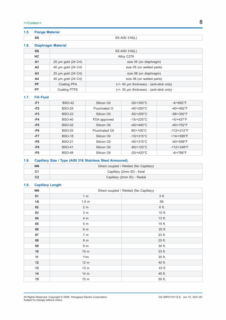
EN 1092-1 B1 typeSize Rating OD B R b f H PCD C/PCS Weight
3/4”
cl. 150 100.0
21.0 42.9
302.0
45.0 69.9 1/2’’-13 UNC / 4x 2.2
cl. 300115.0 29
50.082.6 5/8''-11UNC/4x
3.0
cl. 400-6007.0
55.0 3.1
cl900-1500 130.0 33 63.5 88.9 3/4’-10 UNC/4x 4.6
1"
cl.50 110.0
26.6 50.8
242.0
45.0 79.4 1/2’’ - 13 UNC / 4x 2.5
cl.300125.0 29
50.088.9 5/8’’ - 11 UNC / 4x
3.4
cl.400 - 6007.0
55.0 3.5
cl. 900-1500 150.0 37 69.0 101.6 7/8’’ - 9 UNC / 4x 6.4
1.5"
cl. 150 125.0
40.9 73.0
272.0
98.4 1/2’’ - 13 UNC / 4x 3.4
cl. 300155.0
29114.3 3/4'' - 10 UNC / 4x
5.8
cl. 400 - 60032 7.0
6.0
cl. 900-1500 180.0 123.8 1’’ - 8 UNC / 4x 9.2
ASME 16.5 RF facingSize Rating OD B b R f H PCD C / pcs Weight
DN15PN10-40 95.0
15.32.0
45.0
2.0
48.5 65.0M12 / 4xM12 / 4x
3.5 kg
PN63-100 105.0115.0
29.0 49.5 75.085.0
3.6 kg
DN25PN10-40
25.029.0
68.048.1 4.0 kg
PN63-100 140.0150.0
35.0 55.5100.0
M16 / 4xM16 / 4x
6.8 kg
DN40PN10-40
40.024.0
88.0
3.0
45.5 7.2 kg
PN63-100 170.0 26.0 47.5
125.0
M20 / 4x 6.6 kg
DN50
PN10-16165.0
47.030.0
102.0
48.5 M16 / 4x6.7 kgPN25-40
PN63 180.049.5
135.0 M20 / 4x
PN100 195.0 28.0 145.0 M24 / 4x 9.2 kg
Thickness with flush ports
Flush size (C1) b11/4” NPT B<20 then b1=20
1/2” NPT B<35 then b1=35
All dimensions in mm, weight in kg
Jun.15, 2021-00

34<<Codes>>
All Rights Reserved. Copyright © 2008, Yokogawa Electric Corporation GS 06P01Y01-E-ESubject to change without notice.
34
8. DFS-USL-F Diaphragm Seal - Internal Diaphragm, Flanged type8.1. Model
8.3. Mounting
8.2. Seal Type
TXCM EJA-E / EJX-A 100, 300 & 400 SeriesTXCP EJA-E / EJX-A 130 & 440 Series
TXCD EJA-E / EJX-A 500 & 600 Series - (preferred connection “4” / WN)
DFS-USL-F Diaphragm Seal - Internal Diaphragm, Flanged type
WN5 TXCM with W option =/N5 mandatory option
XN5 TXCD no N5 / W available
8.4. Flange Size & RatingdD (min. span, see page 3)
01A1 1/2” cl. 150 RF cl. 150 RF 81 mm.01A2 1/2” cl. 300 RF cl. 150 RF 81 mm.01A4 1/2” cl. 600 RF cl. 150 RF 81 mm.1AA1 3/4” cl. 150 RF cl. 150 RF 81 mm.1AA2 3/4” cl. 300 RF cl. 150 RF 81 mm.
1AA4 3/4” cl. 600 RF cl. 150 RF 81 mm.02A1 1” cl. 150 RF cl. 150 RF 81 mm.02A1 1” cl. 300 RF cl. 150 RF 81 mm.02A4 1” cl. 600 RF cl. 150 RF 81 mm.04A1 1,5” cl. 150 RF cl. 150 RF 81 mm.04A2 1,5” cl. 300 RF cl. 150 RF 81 mm.
04A4 1,5” cl. 600 RF cl. 150 RF 81 mm.05A1 2” cl. 150 RF cl. 150 RF 81 mm.05A2 2” cl. 300 RF cl. 150 RF 81 mm.05A4 2” cl. 600 RF cl. 150 RF 81 mm.01D4 DN15 PN10-40 form B1 acc. EN 1092-1 81 mm.01D5 DN15 PN63 form B1 acc. EN 1092-1 81 mm.
01D6 DN15 PN100 form B1 acc. EN 1092-1 81 mm.02D4 DN25 PN10-40 form B1 acc. EN 1092-1 81 mm.02D5 DN25 PN63 form B1 acc. EN 1092-1 81 mm.02D6 DN25 PN100 form B1 acc. EN 1092-1 81 mm.04D4 DN40 PN10-40 form B1 acc. EN 1092-1 81 mm.04D5 DN40 PN100 form B1 acc. EN 1092-1 81 mm.04D6 DN40 PN100 form B1 acc. EN 1092-1 81 mm.05D4 DN50 PN10-40 form B1 acc. EN 1092-1 81 mm.05D5 DN50 PN63 form B1 acc. EN 1092-1 81 mm.05D6 DN50 PN100 form B1 acc. EN 1092-1 81 mm.
8.5. Lower part materialSS SS AISI 316(L)
8.6. Diaphragm MaterialSS Stainless Steel AISI 316 LHB Alloy B2
HC Alloy C276
Jun.15, 2021-00

35<<Codes>>
GS 06P01Y01-E-EAll Rights Reserved. Copyright © 2008, Yokogawa Electric CorporationSubject to change without notice.
35
8.6. Diaphragm MaterialDU Duplex 2205I6 Alloy 625M4 Alloy 400
N2 Nickel 201TA TantalumSD Super Duplex 2507S4 AISI304LS2 AISI321A1 25 μm gold (24 Crt)A2 40 μm gold (24 Crt)PT Coating PTFE (+/- 35 μm thickness) (anti-stick only)
8.7. Fill Fluid-F1 BSO-42 Silicon Oil -20/+350°C -4/+662°F
-F2 BSO-25 Fluorinated O -40/+250°C -40/+482°F
-F3 BSO-22 Silicon Oil -50/+200°C -58/+392°F
-F4 BSO-40 FDA approved -15/+225°C +5/+437°F
-F5 BSO-02 Silicon Oil -40/+400°C -40/+752°F
-F6 BSO-03 Fluorinated Oil 80/+100°C -112/+212°F
-F7 BSO-18 Silicon Oil -10/+315°C +14/+599°F
-F8 BSO-21 Silicon Oil -40/+315°C -40/+599°F
-F9 BSO-41 Silicon Oil -80/+120°C -112/+248°F
-F0 BSO-48 Silicon Oil -20/+420°C -4/+788°F
8.8. Capillary Size / Type (AISI 316 Stainless Steel Armoured)NN Direct coupled / Welded (No Capillary)
C1 Capillary (2mm ID) - axial
8.9. Capillary LengthNN Direct coupled / Welded (No Capillary)
01 1 m 3 ft.
1A 1,5 m 5ft.
02 2 m 6 ft.
03 3 m 10 ft
04 4 m 13 ft.
05 5 m 15 ft.
06 6 m 20 ft
07 7 m 23 ft.
08 8 m 25 ft.
09 9 m 30 ft.
10 10 m 33 ft.
11 11m 35 ft.
12 12 m 40 ft.
13 13 m 43 ft
14 14 m 45 ft.
15 15 m 50 ft.
Jun.15, 2021-00

36<<Codes>>
All Rights Reserved. Copyright © 2008, Yokogawa Electric Corporation GS 06P01Y01-E-ESubject to change without notice.
36
8.10. Flush connections lower part/FR01 Flush port Unplugged 1 x ¼” NPT/FR02 Flush port Unplugged 2 x ¼” NPT
/FR03 Flush port Vent plug 1 x ¼” NPT/FR04 Flush port Vent plug 2 x ¼” NPT/FR05 Flush port Blind plugs 1 x ¼” NPT
/FR06 Flush port Blind plugs 2 x ¼” NPT/FR10 Flush port Unplugged 1 x ½” NPT/FR20 Flush port Unplugged 2 x ½” NPT/FR30 Flush port Vent plug 1 x ½” NPT/FR40 Flush port Vent plug 2 x ½” NPT/FR50 Flush port Blind plugs 1 x ½” NPT/FR60 Flush port Blind plugs 2 x ½” NPT/FV91 Pair flush valves BDTV910 for ¼" ports (fitted)/FV92 Pair flush valves BDTV910 for ½” ports (fitted)/FV93 Single flush BDTV910 for 1/4” for ¼” port (fitted)
/FV94 Single flush BDTV910 for 1/2” for ½” port (fitted)
8.11. Options/N5 EJX/EJA100/300/400 + W option Low volume covers by Yokogawa
/FW Full welded construction recomm. for vacuum service (< 500 mbara)
/FWS Full Welded construction for 500/600 series recomm. for vacuum service (< 500 mbara)
/8B8 8 bolts B8 (Max. 248 bar)
/GGA Graphite gasket (up to 343°C)
/CAM Camprofile gasket (up to 500°C) for steam applications
/DM1 Extended Direct mount (80mm) (temp reduction: 100°C)
/DM2 Extended Direct mount (150 mm) temp reduction: 175°C)
/TR Temperature reducer (max. temp. fill fluid allowed)
/IC1 Capillary ID 1 mm. / 0,04”
/BS6 Black sleeve on capillary ≤ 6 m.
/BS15 Black sleeve on capillary > 6 ≤ 15 m.
/K1 Degreasing Treatment I + certificate
/K2 Degreasing Treatment (applicable F2 fill) + certificate
/NACE NACE MR01-75 (ISO15156) or MR0103 (ISO17945) compliance
/BAS Basecal performance calculation report
/DP1 Dye penetrant test pressurized welds + 2.2 EN-10204 test report (Level I)
/DP2 Dye penetrant test pressurized welds + 3.1 EN-10204 test report (Level II)
/LMF Large Male Facing acc. ASME B16.5
Jun.15, 2021-00

37<<Codes>>
GS 06P01Y01-E-EAll Rights Reserved. Copyright © 2008, Yokogawa Electric CorporationSubject to change without notice.
37
8.11. Options/SMF Small Male Facing acc. ASME B16.5
/FF Flat Facing acc. ASME B16.5
/LTF Large Tongue acc. ASME B16.5
/STF Small Tongue Facing acc. ASME B16.5
/LGF Large Groove Facing acc. ASME B16.5
/SGF Small Groove Facing acc. ASME B16.5
/LFF Large Female Facing acc. ASME B16.5
/SFF Small Female Facing acc. ASME B16.5
/RJF Ring Joint Facing acc. ASME B16.5
/A Form A acc. EN1092-1
/B2 Form B2 acc. EN1092-1
/C Form C acc. EN1092-1
/D Form D acc. EN1092-1
/E Form E acc. EN1092-1
/F Form F acc. EN1092-1
/G Form G acc. EN1092-1
/H Form H acc. EN1092-1
/QBDT Quick delivery ex works BADO (< 5 working days)
Dimensions tables
ASME 16.5 RF facingSize Rating OD B b R f H PCD C/PCS Weight
1/2”
cl. 150
140.0 15.840.0 34.9 2.0 67.0
60.3
0.5’’ - 13 UNC / 4x 7.9 kgcl. 30066.7
cl. 400-600 39.0 39 7.0 71.0
3/4”
cl. 150
140.0 21.0
39.0
42.92.0
66.0 69.9 0.5’’ - 13 UNC / 4x
7.9 kgcl. 30044.0
71.082.6 5/8''-11UNC/4x
cl. 400-600 7.0 76.0
Jun.15, 2021-00

38<<Codes>>
All Rights Reserved. Copyright © 2008, Yokogawa Electric Corporation GS 06P01Y01-E-ESubject to change without notice.
38ASME 16.5 RF facing
Size Rating OD B b R f H PCD C/PCS Weight
1"
cl. 150
140.0 26.6
38.0
50.82.0
65.0 79.4 0.5’’ - 13 UNC / 4x
7.9 kgcl. 30041.0
48.0 88.95/8’’ - 11 UNC / 4x
cl. 400 - 600 7.0 50.0 88.9
1.5"
cl. 150 140.0
40.9
38.0
73.02.0
65.0 98.4 1/2’’ - 13 UNC / 4x7.9 kg
cl. 300 44.0 69.0114.3 3/4'' - 10 UNC / 4x
cl. 400 - 600 155.0 45.0 7.0 77.0 8.5 kg
2"
cl. 150 150.0
52.5
29.0
92.12.0
56.0120.7
5/8’’-11 UNC / 4x 7.0 kg
cl. 300 30.0 57.05/8''-11 UNC / 8x 8.0 kg
cl. 400 - 600 160.0 29.0 7.0 61.0 127.0
EN 1092-1 B1 typeSize Rating OD B b R f H PCD C / pcs Weight
DN15PN10-40
140.0
17.340.0
45.0
2.0
67.0 65.0
M12 / 4x
7.9 kg
PN63-100 37.0 64.075.
DN20PN10-40 22.3 38.0
58.065.0
PN63-100 21.7 43.0 70.0 90.0 M16 / 4x
DN25PN10-40
28.535.5
68.062.5 85.0 M12 / 4x
PN63-100 40.0 77.0 100.0M16 / 4x
8.2 kg
DN40PN10-40 150.0 43.1 40.0
88.0
3.0
78.0 110.08.5 kg
PN63-100 170.0 42.5 41.0 79.0125.0
M20 / 4x
DN50
PN10-40 165.054.5
30.0
102.058.0
M16 / 4x7.0 kg
PN63 180.0 30.0 135.0 M20 / 4x
PN10 195.0 53.9 40.0 68.0 145.0 M24 / 4x 7.9 kg
Thickness with flush ports
Flush size (C1) b1
1/4” NPT B<20 then b1=20
1/2” NPT B<35 then b1=35
All dimensions in mm, weight in kg
Jun.15, 2021-00

39<<Codes>>
GS 06P01Y01-E-EAll Rights Reserved. Copyright © 2008, Yokogawa Electric CorporationSubject to change without notice.
39
9. DFS-UST Diaphragm Seal - Internal Diaphragm, Threaded
9.4. Thread & Form - (standard supplied with 4 bolts up to 125 bar and PTFE gasket)dD (min. span, see page 3)
T1NF 1/4” NPT female 50 mm.
T2NF 1/2” NPT female 50 mm.T3NF 3/4” NPT female 50 mm.T4NF 1” NPT female 50 mm.T1NM 1/4” NPT male 50 mm.
T2NM 1/2” NPT male 50 mm.T3NM 3/4” NPT male 50 mm.T4NM 1” NPT male 50 mm.
T1BM 1/4” ISO 228 male 50 mm.
T2BM 1/2” ISO 228 male 50 mm.T3BM 3/4” ISO 228 male 50 mm.
T4BM 1” ISO 228 male 50 mm.
T1BF 1/4” ISO 228 female 50 mm.T2BF 1/2” ISO 228 female 50 mm.T3BF 3/4” ISO 228 female 50 mm.T4BF 1” ISO 228 female 50 mm.T1MM M12*1.5 Metric male 50 mm.
T2MM M20*1.5 Metric male 50 mm.T1MF M12*1.5 Metric female 50 mm.T2MF M20*1.5 Metric female 50 mm.
9.5. Lower part materialSS SS AISI 316(L)
9.6. Diaphragm MaterialSS Stainless Steel AISI 316 LHB Alloy B2
HC Alloy C276DU Duplex 2205I6 Alloy 625M4 Alloy 400
N2 Nickel 201TA TantalumSD Super Duplex 2507
9.1. Model
9.3. Mounting
9.2. Seal Type
TXCM EJA-E100, 300 & 400 Series
TXCP EJA-E130 & 440 Series
TXCD EJA-E500 Series - (preferred connection “4” / WN)
DFS-UST Diaphragm Seal - Internal Diaphragm, Threaded
WN5 TXCM with W option =/N5 mandatory option
XN5 TXCD no N5 / W available
Jun.15, 2021-00

40<<Codes>>
All Rights Reserved. Copyright © 2008, Yokogawa Electric Corporation GS 06P01Y01-E-ESubject to change without notice.
40
Jun.15, 2021-00
9.6. Diaphragm MaterialS4 AISI304LS2 AISI321A1 25 μm gold (24 Crt)A2 40 μm gold (24 Crt)PT Coating PTFE (+/- 35 μm thickness) (anti-stick only)
9.7. Fill Fluid-F1 BSO-42 Silicon Oil -20/+350°C -4/+662°F
-F2 BSO-25 Fluorinated O -40/+250°C -40/+482°F
-F3 BSO-22 Silicon Oil -50/+200°C -58/+392°F
-F4 BSO-40 FDA approved -15/+225°C +5/+437°F
-F5 BSO-02 Silicon Oil -40/+400°C -40/+752°F
-F6 BSO-03 Fluorinated Oil 80/+100°C -112/+212°F
-F7 BSO-18 Silicon Oil -10/+315°C +14/+599°F
-F8 BSO-21 Silicon Oil -40/+315°C -40/+599°F
-F9 BSO-41 Silicon Oil -80/+120°C -112/+248°F
-F0 BSO-48 Silicon Oil -20/+420°C -4/+788°F
9.8. Capillary Size / Type (AISI 316 Stainless Steel Armoured)NN Direct coupled / Welded (No Capillary)
C1 Capillary (2mm ID) - axial
9.9. Capillary LengthNN Direct coupled / Welded (No Capillary)
01 1 m 3 ft.
1A 1,5 m 5ft.
02 2 m 6 ft.
03 3 m 10 ft
04 4 m 13 ft.
05 5 m 15 ft.
06 6 m 20 ft
07 7 m 23 ft.
08 8 m 25 ft.
09 9 m 30 ft.
10 10 m 33 ft.
11 11m 35 ft.
12 12 m 40 ft.
13 13 m 43 ft
14 14 m 45 ft.
15 15 m 50 ft.
9.10. Flush connections lower part/FR01 Flush port Unplugged 1 x ¼” NPT/FR02 Flush port Unplugged 2 x ¼” NPT
/FR03 Flush port Vent plug 1 x ¼” NPT/FR04 Flush port Vent plug 2 x ¼” NPT/FR05 Flush port Blind plugs 1 x ¼” NPT

41<<Codes>>
GS 06P01Y01-E-EAll Rights Reserved. Copyright © 2008, Yokogawa Electric CorporationSubject to change without notice.
41
9.10. Flush connections lower part/FR06 Flush port Blind plugs 2 x ¼” NPT/FR10 Flush port Unplugged 1 x ½” NPT/FR20 Flush port Unplugged 2 x ½” NPT/FR30 Flush port Vent plug 1 x ½” NPT/FR40 Flush port Vent plug 2 x ½” NPT/FR50 Flush port Blind plugs 1 x ½” NPT/FR60 Flush port Blind plugs 2 x ½” NPT/FV91 Pair flush valves BDTV910 for ¼" ports (fitted)/FV92 Pair flush valves BDTV910 for ½” ports (fitted)/FV93 Single flush BDTV910 for 1/4” for ¼” port (fitted)
/FV94 Single flush BDTV910 for 1/2” for ½” port (fitted)
9.11. Options/N5 EJX/EJA100/300/400 + W option Low volume covers by Yokogawa
/FW Full welded construction recomm. for vacuum service (< 500 mbara)
/FWS Full Welded construction for 500/600 series recomm. for vacuum service (< 500 mbara)
/4B8 4 bolts B8 (Max. 150 bar)
/8B2 8 bolts A2-70 (Max. 250 bar)
/8B8 8 bolts B8 (Max. 300 bar)
/GGA Graphite gasket (up to 343°C)
/CAM Camprofile gasket (up to 500°C) for steam applications
/DM1 Extended Direct mount (80mm) (temp reduction: 100°C)
/DM2 Extended Direct mount (150 mm) temp reduction: 175°C)
/TR Temperature reducer (max. temp. fill fluid allowed)
/IC1 Capillary ID 1 mm. / 0,04”
/BS6 Black sleeve on capillary ≤ 6 m.
/BS15 Black sleeve on capillary > 6 ≤ 15 m.
/K1 Degreasing Treatment I + certificate
/K2 Degreasing Treatment (applicable F2 fill) + certificate
/NACE NACE MR01-75 (ISO15156) or MR0103 (ISO17945) compliance
/BAS Basecal performance calculation report
/DP1 Dye penetrant test pressurized welds + 2.2 EN-10204 test report (Level I)
/DP2 Dye penetrant test pressurized welds + 3.1 EN-10204 test report (Level II)
/QBDT Quick delivery ex works BADO (< 5 working days)
Jun.15, 2021-00

42<<Codes>>
All Rights Reserved. Copyright © 2008, Yokogawa Electric Corporation GS 06P01Y01-E-ESubject to change without notice.
42
Dimensions table: Female threaded
Maximum Allowable Operating Pressure: 125 bar
Dimensions table: Male threaded
ASME 1.20.1 – NPT Tapered threadT
Female threadedThread size(C2) dD D H b K C1 weight
1/4” NPT-f
50.0 85.0
37.5 19.0
70.0 3/8"UNC 2.5 kg1/2” NPT-f
3/4” NPT-f43.5 25.0
1” NPT-f
Male threadedThread size(C2) dD D H H1 b K C1 C3 SW weight
1/4” NPT-m
50.0 85.0 37.5
65.5
19.0 70.0 3/8”UNC
6.0 22
< 2.5 kg1/2” NPT-m 68.5 8.0
3/4” NPT-m 71.5 10.0 27
1” NPT-m 87.5 12.0 36
ISO 228 – G (BSP) Parallel thread
Female threadedThread size(C2) dD D H b K C1 weight
G ¼
50.0 85.0
37.5 19.0
70.0 3/8"UNC 2.5 kgG ½
G ¾43.5 25.0
G 1
Male threadedThread size(C2) dD D H H1 b K C1 C3 SW weight
1/4” NPT-m
50.0 85.0 37.5
65.5
19.0 70.0 3/8”UNC
6.022
< 2.5 kg1/2” NPT-m 68.5 8.0
3/4” NPT-m 71.5 10.0 27
1” NPT-m 87.5 12.0 36
Jun.15, 2021-00

43<<Codes>>
GS 06P01Y01-E-EAll Rights Reserved. Copyright © 2008, Yokogawa Electric CorporationSubject to change without notice.
43
DIN 13-1 – Metric ISO thread
Female threaded
Thread size(C2) dD D H b K C1 weight
M12x1.550.0 85.0 37.5 19.0 70.0 3/8"UNC 2.5 kg
M20x1.5
Male threadedThread size(C2) dD D H H1 b K C1 C3 SW weight
M12x1.550.0 85.0 37.5
65.519.0 70.0 3/8"UNC
6.022 2.5 kg
M20x1.5 68.5 8.0
Thickness with flush ports
Flush size (C1) b1
1/4” G/NPT b1=20
1/2” G/NPT b1=35
All dimensions in mm, weight in kg
Jun.15, 2021-00

44<<Codes>>
All Rights Reserved. Copyright © 2008, Yokogawa Electric Corporation GS 06P01Y01-E-ESubject to change without notice.
44
10. DFS-USL-T Diaphragm Seal - Internal Diaphragm, Threaded
10.4. Thread & Form (standard supplied with 8 bolts up to 125 bar and PTFE gasket)dD (min. span, see page 3)
T1NF 1/4” NPT female 81 mm.
T2NF 1/2” NPT female 81 mm.
T3NF 3/4” NPT female 81 mm.
T4NF 1” NPT female 81 mm.T1NM 1/4” NPT male 81 mm.
T2NM 1/2” NPT male 81 mm.
T3NM 3/4” NPT male 81 mm.T4NM 1” NPT male 81 mm.T1BM 1/4” ISO 228 male 81 mm.T2BM 1/2” ISO 228 male 81 mm.T3BM 3/4” ISO 228 male 81 mm.T4BM 1” ISO 228 male 81 mm.T1BF 1/4” ISO 228 female 81 mm.T2BF 1/2” ISO 228 female 81 mm.T3BF 3/4” ISO 228 female 81 mm.T4BF 1” ISO 228 female 81 mm.
T1MM M12*1.5 Metric male 81 mm.T2MM M20*1.5 Metric male 81 mm.T1MF M12*1.5 Metric female 81 mm.T2MF M20*1.5 Metric female 81 mm.
10.5. Lower part materialSS SS AISI 316(L)
10.6. Diaphragm MaterialSS Stainless Steel AISI 316 L
HB Alloy B2
HC Alloy C276
DU Duplex 2205
I6 Alloy 625
M4 Alloy 400
N2 Nickel 201
TA Tantalum
10.1. Model
10.3. Mounting
10.2. Seal Type
TXCM EJA-E100, 300 & 400 Series
TXCP EJA-E130 & 440 Series
TXCD EJA-E500 Series (preferred connection “4” / WN)
DFS-USL-T Diaphragm Seal - Internal Diaphragm, Threaded
WN5 EJAM with N5 / EJXM / TXCM with W option =/N5 mandatory option
XN5 EJAD / EJXD / TXCD no N5 / W available
Jun.15, 2021-00

45<<Codes>>
GS 06P01Y01-E-EAll Rights Reserved. Copyright © 2008, Yokogawa Electric CorporationSubject to change without notice.
45
10.6. Diaphragm MaterialSD Super Duplex 2507
S4 AISI304L
S2 AISI321
A1 25 μm gold (24 Crt)
A2 40 μm gold (24 Crt)PT Coating PTFE (+/- 35 μm thickness) (anti-stick only)
10.7. Fill Fluid -F1 BSO-42 Silicon Oil -20/+350°C -4/+662°F
-F2 BSO-25 Fluorinated Oil -40/+250°C -40/+482°F
-F3 BSO-22 Silicon Oil -50/+200°C -58/+392°F
-F4 BSO-40 FDA approved -15/+225°C +5/+437°F
-F5 BSO-02 Silicon Oil -40/+400°C -40/+752°F
-F6 BSO-03 Fluorinated Oil -80/+100°C -112/+212°F
-F7 BSO-18 Silicon Oil -10/+315°C +14/+599°F
-F8 BSO-21 Silicon Oil -40/+315°C -40/+599°F
-F9 BSO-41 Silicon Oil -80/+120°C -112/+248°F
-F0 BSO-48 Silicon Oil -20/+420°C -4/+788°F
10.8. Capillary Size / Type (AISI 316 Stainless Steel Armoured)NN Direct coupled / Welded (No Capillary)
C1 Capillary (2mm ID) - axial
10.9. Capillary LengthNN Direct coupled / Welded (No Capillary)
01 1 m 3 ft1A 1,5 m 5 ft
02 2 m 6 ft03 3 m 10 ft04 4 m 13 ft05 5 m 15 ft06 6 m 20 ft07 7 m 23 ft08 8 m 25 ft09 9 m 30 ft10 10 m 33 ft11 11 m 35 ft12 12 m 40 ft13 13 m 43 ft
14 14 m 45 ft15 15 m 50 ft
10.10. Flush connections lower part/FR01 Flush port Unplugged 1 x ¼” NPT/FR02 Flush port Unplugged 2 x ¼” NPT
/FR03 Flush port Vent plug 1 x ¼” NPT/FR04 Flush port Vent plug 2 x ¼” NPT/FR05 Flush port Blind plugs 1 x ¼” NPT/FR06 Flush port Blind plugs 2 x ¼” NPT
Jun.15, 2021-00

46<<Codes>>
All Rights Reserved. Copyright © 2008, Yokogawa Electric Corporation GS 06P01Y01-E-ESubject to change without notice.
46
10.11. Options/N5 EJX/EJA100/300/400 + W option Low volume covers by Yokogawa
/FW Full welded construction recomm. for vacuum service (< 500 mbara)
/FWS Full Welded construction for 500/600 series recomm. for vacuum service (< 500 mbara)
/8B8 8 bolts B8 (Max. 248 bar)
/GGA Graphite gasket (up to 343°C)
/CAM Camprofile gasket (up to 500°C) for steam applications
/DM1 Extended Direct mount (80mm) (temp reduction: 100°C)
/DM2 Extended Direct mount (150 mm) (temp reduction: 175°C)
/TR Temperature reducer (max. temp. fill fluid allowed)
/IC1 Capillary ID 1 mm. / 0,04”
/BS6 Black sleeve on capillary ≤ 6 m.
/BS15 Black sleeve on capillary > 6 ≤ 15 m.
/K1 Degreasing Treatment I + certificate
/K2 Degreasing Treatment (applicable F2 fill) + certificate
/NACE NACE MR01-75 (ISO15156) or MR0103 (ISO17945) compliance
/BAS Basecal performance calculation report
/DP1 Dye penetrant test pressurized welds + 2.2 EN-10204 test report (Level I)
/DP2 Dye penetrant test pressurized welds + 3.1 EN-10204 test report (Level II)
/QBDT Quick delivery ex works BADO (< 5 working days)
Jun.15, 2021-00
10.10. Flush connections lower part/FR10 Flush port Unplugged 1 x ½” NPT
/FR20 Flush port Unplugged 2 x ½" NPT
/FR30 Flush port Vent plug 1 x ½” NPT
/FR40 Flush port Vent plug 2 x ½” NPT
/FR50 Flush port Blind plugs 1 x ½” NPT
/FR60 Flush port Blind plugs 2 x ½” NPT
/FV91 Pair flush valves BDTV910 for ¼” ports (fitted)
/FV92 Pair flush valves BDTV910 for ½” ports (fitted)
/FV93 Single flush BDTV910 for 1/4” for ¼” port (fitted)
/FV94 Single flush BDTV910 for 1/2” for ½” port (fitted)

47<<Codes>>
GS 06P01Y01-E-EAll Rights Reserved. Copyright © 2008, Yokogawa Electric CorporationSubject to change without notice.
47
Dimensions tables: Male threadedDimensions tables: Female threaded
Maximum Allowable Operating Pressure: 125 bar
ASME 1.20.1 – NPT Tapered thread
Female threadedThread size (C2) dD D H b K C1 Weight
1/4” NPT-f
81.0 140.0 55.0 20.0 114.0 M10 < 4.5 kg1/2” NPT-f3/4” NPT-f
1” NPT-f
Male threadedThread size (C2) dD D H H1 b K C1 C3 SW Weight
1/4” NPT-m
81.0 140.0 55.0
83.0
20.0 114.0 M10
6.022
< 4.5 kg1/2” NPT-m 86.0 8.0
3/4” NPT-m 89.0 10.0 27
1” NPT-m 105.0 12.0 36
ISO 228 – G (BSP) Parallel thread
Female threaded
Thread size (C2) dD D H b K C1 Weight
G 1/4
81.0 140.0 55.0 20.0 114.0 M10 < 4.5 kgG 1/2G 3/4
G 1
Male threadedThread size (C2) dD D H H1 b K C1 C3 SW Weight
G 1/4 A
81.0 140.0 55.0
83.0
20.0 114.0 M10
6.022
< 4.5 kgG 1/2 A 86.0 8.0
G 3/4 A 89.0 10.0 27
G 1 A 105.0 12.0 36
Jun.15, 2021-00

48<<Codes>>
All Rights Reserved. Copyright © 2008, Yokogawa Electric Corporation GS 06P01Y01-E-ESubject to change without notice.
48
Flush size (C4) b11/4” G/NPT b1=20
1/2” G/NPT b1=35
All dimensions in mm, weight in kg
Thickness with flush ports
DIN 13-1 – Metric ISO thread
Female threadedThread size (C2) dD D H b K C1 Weight
M12x1.581.0 140.0 55.0 20.0 114.0 M10 < 4.5 kg
M20x1.5
Male threadedThread size (C2) dD D H H1 b K C1 C3 SW Weight
M12x1.581.0 140.0 55.0
83.020.0 114.0 M10
6.022 < 4.5 kg
M20x1.5 86.0 8.0
Jun.15, 2021-00

49<<Codes>>
GS 06P01Y01-E-EAll Rights Reserved. Copyright © 2008, Yokogawa Electric CorporationSubject to change without notice.
49
Dimensions table: PSThread size(C2) dD R SW OD H1 H
1”Male 23.5 28.0 SW 41 45 28 58
1,5”Male 35.0 42.0 SW 46 55 34 64
2”Male 44.0 47.0 SW 54 62 47 65
All dimensions in mm, weight in kg
11. DFS-PS Diaphragm Seal - Plug Seal
11.4. Thread & FormdD (min. span, see page 3)
-T4NM 1” NPT male PN600 23,5 mm.
-T5NM 1,5” NPT male PN400 35 mm.-T5NM 2” NPT male PN250 44 mm.-T4BM 1” ISO 228 BSP male PN600 23,5 mm.-T5BM 1,5" ISO 228 BSP male PN400 35 mm.
-T6BM 2” ISO 228 BSP male PN250 44 mm.
11.5. Body materialSS SS AISI 316(L)
11.6. Diaphragm MaterialSS Stainless Steel AISI 316 LHC Alloy C276
11.7. Fill Fluid- F3 SS AISI 316(L) BSO-22 Silicon Oil -50/+200°C -58/+392°F
11.8. Capillary Size / Type (AISI 316 Stainless Steel Armoured)NN Direct coupled / Welded (No Capillary)
11.9. Capillary LengthNN Direct coupled / Welded (No Capillary)
11.1. Model
11.3. Mounting
11.2. Seal Type
TXCD EJA-E / EJX-A 500 & 600 Series - (preferred connection “4” / WN)
DFS-PS Diaphragm Seal - Plug Seal
XN5 TXCD no N5 / W available
Jun.15, 2021-00
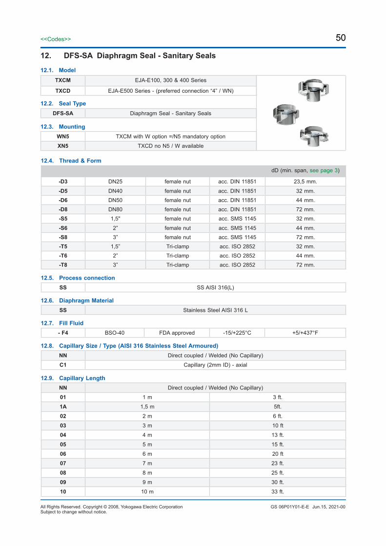
50<<Codes>>
All Rights Reserved. Copyright © 2008, Yokogawa Electric Corporation GS 06P01Y01-E-ESubject to change without notice.
50
12. DFS-SA Diaphragm Seal - Sanitary Seals
12.4. Thread & FormdD (min. span, see page 3)
-D3 DN25 female nut acc. DIN 11851 23,5 mm.
-D5 DN40 female nut acc. DIN 11851 32 mm.-D6 DN50 female nut acc. DIN 11851 44 mm.-D8 DN80 female nut acc. DIN 11851 72 mm.-S5 1,5" female nut acc. SMS 1145 32 mm.
-S6 2” female nut acc. SMS 1145 44 mm.-S8 3” female nut acc. SMS 1145 72 mm.-T5 1,5” Tri-clamp acc. ISO 2852 32 mm.-T6 2” Tri-clamp acc. ISO 2852 44 mm.-T8 3” Tri-clamp acc. ISO 2852 72 mm.
12.5. Process connectionSS SS AISI 316(L)
12.6. Diaphragm MaterialSS Stainless Steel AISI 316 L
12.7. Fill Fluid- F4 BSO-40 FDA approved -15/+225°C +5/+437°F
12.8. Capillary Size / Type (AISI 316 Stainless Steel Armoured)NN Direct coupled / Welded (No Capillary)
C1 Capillary (2mm ID) - axial
12.9. Capillary LengthNN Direct coupled / Welded (No Capillary)
01 1 m 3 ft.
1A 1,5 m 5ft.
02 2 m 6 ft.
03 3 m 10 ft
04 4 m 13 ft.
05 5 m 15 ft.
06 6 m 20 ft
07 7 m 23 ft.
08 8 m 25 ft.
09 9 m 30 ft.
10 10 m 33 ft.
12.1. Model
12.3. Mounting
12.2. Seal Type
TXCM EJA-E100, 300 & 400 Series
TXCD EJA-E500 Series - (preferred connection “4” / WN)
DFS-SA Diaphragm Seal - Sanitary Seals
WN5 TXCM with W option =/N5 mandatory option
XN5 TXCD no N5 / W available
Jun.15, 2021-00

51<<Codes>>
GS 06P01Y01-E-EAll Rights Reserved. Copyright © 2008, Yokogawa Electric CorporationSubject to change without notice.
51
12.9. Capillary Length11 11m 35 ft.
12 12 m 40 ft.
13 13 m 43 ft
14 14 m 45 ft.
15 15 m 50 ft.
12.10. Options/N5 EJX/EJA100/300/400 + W option Low volume covers by Yokogawa
/FW Full welded construction recomm. for vacuum service (< 500 mbara)
/FWS Full Welded construction for 500/600 series recomm. for vacuum service (< 500 mbara)
/DM1 Extended Direct mount (80mm) (temp reduction: 100°C)
/DM2 Extended Direct mount (150 mm) temp reduction: 175°C)
/TR Temperature reducer (max. temp. fill fluid allowed)
/IC1 Capillary ID 1 mm. / 0,04”
/BS6 Black sleeve on capillary ≤ 6 m.
/BS15 Black sleeve on capillary > 6 ≤ 15 m.
/BAS Basecal performance calculation report
/DP1 Dye penetrant test pressurized welds + 2.2 EN-10204 test report (Level I)
/DP2 Dye penetrant test pressurized welds + 3.1 EN-10204 test report (Level II)
/QBDT <5 working days ex works BADO or rush charge compensation
Dimensions table: SAF DIN 11851size rating dD OD H1 H E C1
DN25PN40
3.5 63.021.0
50.0
35.0 Rd52 x 1/6”
DN40 78.0 48.0 Rd65 x 1/6”
DN50PN25
44.0 92.0 22.0 40.0 Rd78 x 1/6”
DN80 72.0 127.0 29.0 38.0 93. Rd110 x 1/6”
Jun.15, 2021-00

52<<Codes>>
All Rights Reserved. Copyright © 2008, Yokogawa Electric Corporation GS 06P01Y01-E-ESubject to change without notice.
52
SAT - Tri-Clamp ISO - 285230.0 DN For pipe rating dD D H E
1.5” 25 25.4 x 22.6PN40
32.0 50.58
30.0
2” 40 40.6 x 37.6 44.0 64.0 50.0
3” 76 76.7 x 72.9 PN25 72.0 91.0 76.0
SAF SMS 1145size rating dD OD H1 H E C1
1.5”PN40
32.0 74.0 21.050.0 40.0
Rd60 x 1/6”
2” 44.0 84.0 Rd70 x 1/6”
Jun.15, 2021-00

53<<Codes>>
GS 06P01Y01-E-EAll Rights Reserved. Copyright © 2008, Yokogawa Electric CorporationSubject to change without notice.
53
13. Open Flanged Process Connection
13.3. Flange Size & Rating
-A11 1” cl. 150 RF acc. ASME B16.5
-A13 1” cl. 300 RF acc. ASME B16.5-A16 1” cl. 600 RF acc. ASME B16.5-A21 2” cl. 150 RF acc. ASME B16.5-A23 2” cl. 300 RF acc. ASME B16.5
-A26 2” cl. 600 RF acc. ASME B16.5
-A31 3” cl. 150 RF acc. ASME B16.5-A33 3” cl. 300 RF acc. ASME B16.5-A36 3” cl. 600 RF acc. ASME B16.5-D25 DN25 PN10-40 form B1 acc. EN 1092-1-D40 DN40 PN10-40 form B1 acc. EN 1092-1-D50 DN50 PN10-40 form B1 acc. EN 1092-1-D80 DN80 PN10-40
13.4. Flange materialSS SS AISI 316(L)
13.5. MountingNN Direct mount/ Welded (Distancer 50 mm for TXCD; 80 mm. For TXCM)
13.6. Options/FL Filter (copper)
/QBDT Quick delivery ex works BADO (< 5 working days)
For dimensions tables, see flange dimensions tables on DFS-BF pages
13.1. Model
TXCM EJA-E / EJX-A 100, 300 & 400 Series
TXCD EJA-E500 Series - (preferred connection “4” / WN)
13.2. Seal Type
DFS-FPC Open Flanged Process Connection
Jun.15, 2021-00

54
All Rights Reserved. Copyright © 2008, Yokogawa Electric Corporation GS 06P01Y01-E-E
<<Codes>>
Jun.15, 2021-00Printed in The NetherlandsSubject to change without notice.
YOKOGAWA ELECTRIC CORPORATIONWorld Headquarters9-32, Nakacho 2-chome, Musashino-shiTokyo 180-8750Japanwww.yokogawa.com
YOKOGAWA CORPORATION OF AMERICA2 Dart RoadNewnan GA 30265USAwww.yokogawa.com/us
YOKOGAWA EUROPE BVEuroweg 23825 HD AMERSFOORTThe Netherlandswww.yokogawa.com/eu
YOKOGAWA ELECTRIC ASIA Pte. LTD.5 Bedok South RoadSingapore 469270Singaporewww.yokogawa.com/sg
YOKOGAWA CHINA CO. LTD.3F Tower D Cartelo Crocodile BuildingNo.568 West Tianshan Road Changing DistrictShanghai, Chinawww.yokogawa.com/cn
YOKOGAWA MIDDLE EAST B.S.C.(c)P.O. Box 10070, ManamaBuilding 577, Road 2516, Busaiteen 225Muharraq, Bahrainwww.yokogawa.com/bh
Yokogawa has an extensive sales and distribution network. Please refer to the European website (www.yokogawa.com/eu) to contact your nearest representative.


![User’s Manual EJX and EJA-E Series Differential Pressure ... · [EJX series Communication Manual] Models Document No. Style DPharp HART 5/HART 7 Communication Type IM 01C25T01-06EN](https://img.pdfslide.us/doc/110x75/5eda7023b3745412b5715724/useras-manual-ejx-and-eja-e-series-differential-pressure-ejx-series-communication.jpg)