Embed Size (px)
Citation preview
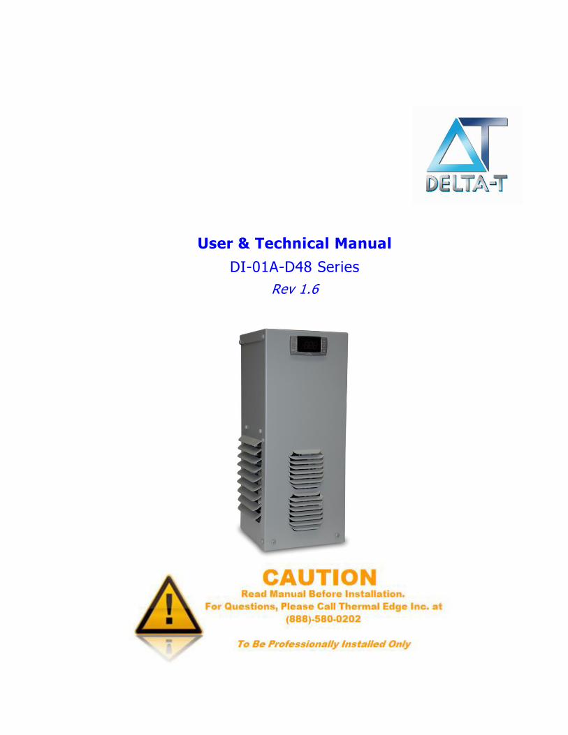
User & Technical Manual
DI-01A-D48 Series
Rev 1.6
4421 Tradition Trail ● Plano, Texas 75093 ● 972-964-2700 ● 800-836-7472
URL: www.iscenclosurecooling.com ● Email: [email protected]
SP-ENG-211-D48-02 Rev 1.6 2 | P a g e
Title: DI-01A-D48 Air Conditioner User & Technical Manual Department: Engineering Objective: To provide important information for maintenance, diagnostics and advance operations of the ISC Inc CS011-D48, 48 VDC Series Air Conditioners. Revision History:
Rev Date Owner Description of Changes
1.0 06-22-2015 B. Slotnick Initial Release
1.1 01-13-2016 B. Slotnick Update system schematic
1.2 07-03-2017 B. Slotnick Change Outdoor Option to Remote Controller
1.3 08-31-2017 B. Slotnick Updated replacement temperature probe information
1.5 10-05-2017 B. Slotnick Added replacement parts to warranty statement & new label template
1.6 02-02-2018 B. Slotnick Updated unit specifications
Statement of Confidentiality
The Manual and other materials contain proprietary information, comprising ISC Inc Inc.'s trade secrets.
Please maintain the confidentiality of all proprietary information during and after the term of the use agreement.
Also, please refrain from using this proprietary information in any other manner, including in any other
business, without ISC Inc Inc.’s written approval.
ISC Inc Inc. reserves the right to revise and otherwise modify the Manual to reflect changes in the
requirements, standards, and operating recommendations. The Manual is the sole property of ISC Inc Inc. It
must be returned upon the expiration or the termination of the term of use agreement.
By accepting the Manual you have read and understand the Statement of Confidentiality and will abide by its
terms and conditions.
4421 Tradition Trail ● Plano, Texas 75093 ● 972-964-2700 ● 800-836-7472
URL: www.iscenclosurecooling.com ● Email: [email protected]
SP-ENG-211-D48-02 Rev 1.6 3 | P a g e
TABLE OF CONTENTS Overview 4
Inspecting the Equipment 4
Unpacking the Air Conditioner 4
Moving the Air Conditioner 5
Unit Label 5
Operation 6
Preliminary Testing 6
Mounting the Air Conditioner 7
Unit Specifications 8
Options 10
System Faults 13
Digital Temperature Controller Programming 13
Preventative Maintenance 16
Field Serviceable Parts 17
Safety Information 17
Troubleshooting Guide 18
Physical Dimensions 21
Electrical Schematic 23
Warranty Information 24
Return Material Authorization (RMA) Procedure 25
Appendix A – Power Connector 26
4421 Tradition Trail ● Plano, Texas 75093 ● 972-964-2700 ● 800-836-7472
URL: www.iscenclosurecooling.com ● Email: [email protected]
SP-ENG-211-D48-02 Rev 1.6 4 | P a g e
Overview Thank you for your purchase of the ISC Inc Special Purpose Air Conditioner. Our air conditioning equipment is carefully designed to cool and dehumidify the air in electronic component enclosures. ISC Inc has designed air conditioners for all types of electronic equipment enclosures providing capacity from 1,000 to 20,000 BTUH. This manual will guide you through the installation, maintenance, diagnostics and advance operations of the DI-01A Series Air Conditioners. This manual contains important information for the end-user who installs, maintains and/or operates the DI-01A Air Conditioner.
Technical Support By Phone: 972-964-2700 / 800-836-7472 (Monday – Friday, 7:30 am – 5:00 pm Central Time)
By Email: [email protected]
Our goal is to have continuous improvement for both our equipment and our documentation. We rely on and appreciate your feedback to help us achieve our goal. Our technical support team is glad to work with you if you require additional technical information not provided in this manual.
Inspecting the Equipment
ISC Inc air conditioning equipment is designed, manufactured and packed to prevent damage from normal handling, shock and vibration during shipment. It is necessary to inspect your equipment upon receipt to ensure that there is no visual or hidden damage. Upon receipt of the equipment, ensure that it is always top side up as indicated by “THIS SIDE UP” labels. This ensures that the compressor oil is not displaced. Note: If the equipment has been on its side it must be put upright for at least 24 hours before installing or running to ensure the compressor oil has returned to the compressor. All physical damage to packing or signs of damage to the equipment must be noted on the freight bill of lading. Packages must be opened after receipt and inspected for any internal or concealed damage to the equipment and to verify proper count and order fulfillment. Delivery without the pallet, not top side up, other freight on top, damaged or wet should be refused.
Unpacking the Air Conditioner
Always keep air conditioner top up as shown by the packaging label and arrows. If the unit is to be transported after initial unpacking, place air conditioner back in original packing to prevent damage. For shipment by freight carrier, repack as received and re-band to the pallet. Note: Shipping without being strapped to the pallet may result in tipping and damage, this will void the warranty.
4421 Tradition Trail ● Plano, Texas 75093 ● 972-964-2700 ● 800-836-7472
URL: www.iscenclosurecooling.com ● Email: [email protected]
SP-ENG-211-D48-02 Rev 1.6 5 | P a g e
Moving the Air Conditioners
Read this section completely before running or installing your ISC Inc air conditioning equipment. Note: You will need to perform a Preliminary Test before mounting the air conditioner. Refer to the Preliminary Test section in this manual for instructions on how to run this test. You will also need to prepare the enclosure that is to be cooled for mounting in accordance with this manual and the template supplied. Note: ISC Inc air conditioning equipment must be mounted vertically with a minimum of 3” air space for condenser air return and supply. If necessary, equipment may be mounted at up to a 5 degree angle (rotary compressors) without damaging the compressor. See Mounting the Air Conditioner for more information. If air conditioner is to be shipped or transported at any time; pack in original packaging and strap to pallet to prevent damage. Air conditioner must be kept upright at all times. Air conditioners are not designed to be shipped attached to an equipment enclosure. Air conditioners shipped which have internal damage due to shipping while attached to enclosures are warranty voided.
Unit Label
Each air conditioner has a unit label, be sure to record the data from the label to the template below and keep this information in a safe place for warranty and ordering parts. To prevent damage to equipment, electrical panel and wiring, and to prevent personal injury, assure that the power source is compatible with the equipment before operating. When recharging, refrigeration type and amount must be the same as shown on the unit label or air conditioner will not operate properly or may be damaged and may result in the warranty voided and UL listing voided.
Voltage:_________________ Frequency:__________Hz Phase:__________
Current Rating (A): Cooling:___________ Heat:___________
Max Fuse:____________ Min. Circuit Ampacity:________
Refrigerant:______________ Ounces:_______________
Design Pressure: High Side PSI:__________ Low Side PSI:__________
NEMA Type:______ IP:______
Model:________________________________________
S/N:__________________________________________
Operation
Delta-T air conditioners will lower (or increase as necessary) the temperature inside an enclosure to ensure its proper operational temperature. Our air conditioners, when sized properly, will provide cooling or heating automatically controlled by the digital controller. Delta-T air conditioners operate as a “closed loop” system with no exposure or introduction of outside air. This ensures that the enclosure is separated from, and is not contaminated with, ambient air, dirt, chemicals, dust, moisture or foreign matter so that sensitive enclosure components are protected and are kept at your required operational temperature.
4421 Tradition Trail ● Plano, Texas 75093 ● 972-964-2700 ● 800-836-7472
URL: www.iscenclosurecooling.com ● Email: [email protected]
SP-ENG-211-D48-02 Rev 1.6 6 | P a g e
An air conditioner is designed to dehumidify and extract heat from an area, or provide heat to an area. The cooling is done using a simple refrigeration cycle. A product of this simple refrigeration cycle is excess humidity that condenses to a liquid. Delta-T air conditioners are designed using an advanced refrigeration cycle and are equipped with a Condensate Removal System that changes the excess humidity liquid into a vapor which is then vented to the atmosphere. In the event of excess water vapor when the enclosure door has been left open there is an overflow hole on the bottom of every unit. Please contact ISC Inc. if you encounter excess water coming from your air conditioner.
Preliminary Testing
Before mounting the air conditioner to the enclosure, test for proper operation. Follow the steps below prior to installation.
WARNINGS The air conditioner must sit upright for 24 hours to assure the compressor oil has drained down to the compressor. Check the unit label to assure the electric power available to the air conditioner is the proper voltage and phase. Check the electric power source for proper ground wire and neutral wire installation per 2008 NEC. Assure that the electric power is protected by a circuit protection device; refer to the Unit Specification section in this manual for proper circuit protection sizing.
Connect a power source to the air conditioner to start the evaporator fan and, if desired, change the set point. Refer to Digital Temperature Controller Programming section on this manual for details on changing the set point. Factory default settings should be satisfactory; however you may want to adjust heat, cooling and alarm set points for your specific application.
The condenser fan is controlled by the refrigerant pressure and will turn on later when the operating pressure builds up. This feature allows low ambient operation and reduces current inrush at initial power on.
Run the air conditioner for 15 minutes; during this time the condenser fan will turn on after the condenser coil warms up. Note: Ambient Temperature must be at least 75°F.
Turn the unit off if the equipment makes any unexpected or hard mechanical noises or vibrations and refer to the troubleshooting guide in this manual.
The supply cold air should be at least 10°F colder than the return air entering the unit. If it is not, refer to the troubleshooting guide in this manual;
When you are satisfied that the unit is operating properly, turn unit off, disconnect the power and mount the unit on the enclosure in accordance with the Mounting the Air Conditioner section in this manual.
4421 Tradition Trail ● Plano, Texas 75093 ● 972-964-2700 ● 800-836-7472
URL: www.iscenclosurecooling.com ● Email: [email protected]
SP-ENG-211-D48-02 Rev 1.6 7 | P a g e
Mounting the Air Conditioner
Using the template supplied, determine where the air conditioner is to be mounted and assure that all required cuts and holes will not interfere with or damage the enclosure or its contents. Assure that there is a 3” clearance between walls / obstructions and the air conditioner for the condenser supply air and return air flow so that it is not restricted. Restricted condenser air flow will affect the air conditioner’s performance. Note: The DI-01A series is constructed with two condenser coils so that it is permissible to provide less than a 3” clearance for the supply air to one of the coils without affecting performance. Mount the air conditioner high on the enclosure in order to cool the hot air at the top of the enclosure. Position the unit where the cold air can circulate across the width of the enclosure to cool it all the way across. Once proper mounting placement is determined, turn the enclosure equipment off, if possible, to prevent damage. Drill and cut the holes as indicated on the mounting template. Install insulation gasket as required to ensure an air tight closed loop seal. Be cautious not to let any cutting debris fall into the enclosure. Hang the air conditioner on the easy hang flange and from inside the enclosure use the fasteners supplied to attach the air conditioner to the enclosure. Ensure that these fasteners are tight in order to prevent the unit from falling off the enclosure. These fasteners should be checked periodically to ensure that they have not become loose due to vibration. The air conditioner is provided with a power terminal block. Ensure that the power supplied is compatible with the air conditioner’s power requirements. Properly connect the unit to a power circuit that meets the equipment requirements and provide a circuit protection device based on the Unit Specifications section of this manual. See Appendix A for Phoenix Contact power connector instructions.
After mounting the air conditioner, replace/close the enclosure door and start air conditioner; test for air leaks to assure a proper closed loop air seal and run test the unit to assure proper operation after mounting. If any cold air leaks are found, check for proper mounting and apply silicone-free Lexel seal if leaks persist. Assure that the air conditioner’s condenser inlet air filter is installed properly and cleaned regularly.
CAUTION If mounting the air conditioner to the enclosure door, confirm with the enclosure manufacturer that the door’s hinges will support the air conditioner’s added weight (see equipment specifications). Ensure that when the door is fully open that the enclosure will not topple over due to the off-center load.
4421 Tradition Trail ● Plano, Texas 75093 ● 972-964-2700 ● 800-836-7472
URL: www.iscenclosurecooling.com ● Email: [email protected]
SP-ENG-211-D48-02 Rev 1.6 8 | P a g e
Unit Specifications
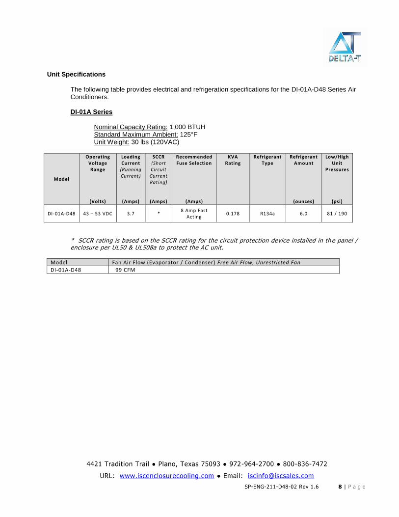
The following table provides electrical and refrigeration specifications for the DI-01A-D48 Series Air Conditioners.
DI-01A Series Nominal Capacity Rating: 1,000 BTUH Standard Maximum Ambient: 125°F Unit Weight: 30 lbs (120VAC)
Model
Operating Voltage Range
(Volts)
Loading Current
(Running Current)
(Amps)
SCCR (Short Circuit Current Rating)
(Amps)
Recommended Fuse Selection
(Amps)
KVA Rating
Refrigerant Type
Refrigerant Amount
(ounces)
Low/High Unit
Pressures
(psi)
DI-01A-D48 43 – 53 VDC 3.7 * 8 Amp Fast
Acting 0.178 R134a 6.0 81 / 190
* SCCR rating is based on the SCCR rating for the circuit protection device installed in th e panel / enclosure per UL50 & UL508a to protect the AC unit.
Model Fan Air Flow (Evaporator / Condenser) Free Air Flow, Unrestricted Fan
DI-01A-D48 99 CFM
4421 Tradition Trail ● Plano, Texas 75093 ● 972-964-2700 ● 800-836-7472
URL: www.iscenclosurecooling.com ● Email: [email protected]
SP-ENG-211-D48-02 Rev 1.6 9 | P a g e
THIS PAGE IS INTENTIONALLY LEFT BLANK
4421 Tradition Trail ● Plano, Texas 75093 ● 972-964-2700 ● 800-836-7472
URL: www.iscenclosurecooling.com ● Email: [email protected]
SP-ENG-211-D48-02 Rev 1.6 10 | P a g e
Options
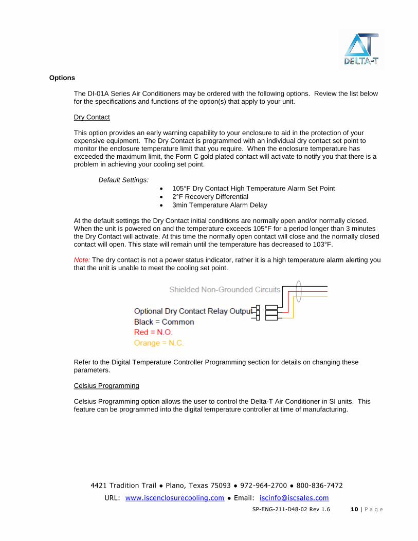
The DI-01A Series Air Conditioners may be ordered with the following options. Review the list below for the specifications and functions of the option(s) that apply to your unit. Dry Contact This option provides an early warning capability to your enclosure to aid in the protection of your expensive equipment. The Dry Contact is programmed with an individual dry contact set point to monitor the enclosure temperature limit that you require. When the enclosure temperature has exceeded the maximum limit, the Form C gold plated contact will activate to notify you that there is a problem in achieving your cooling set point.
Default Settings:
105°F Dry Contact High Temperature Alarm Set Point
2°F Recovery Differential
3min Temperature Alarm Delay
At the default settings the Dry Contact initial conditions are normally open and/or normally closed. When the unit is powered on and the temperature exceeds 105°F for a period longer than 3 minutes the Dry Contact will activate. At this time the normally open contact will close and the normally closed contact will open. This state will remain until the temperature has decreased to 103°F. Note: The dry contact is not a power status indicator, rather it is a high temperature alarm alerting you that the unit is unable to meet the cooling set point.
Refer to the Digital Temperature Controller Programming section for details on changing these parameters.
Celsius Programming Celsius Programming option allows the user to control the Delta-T Air Conditioner in SI units. This feature can be programmed into the digital temperature controller at time of manufacturing.
4421 Tradition Trail ● Plano, Texas 75093 ● 972-964-2700 ● 800-836-7472
URL: www.iscenclosurecooling.com ● Email: [email protected]
SP-ENG-211-D48-02 Rev 1.6 11 | P a g e
External Heat Output This option allows you to add an external heater to be located anywhere in your enclosure. These external heaters are ideal for focusing on individual sections of the enclosure without having a large capacity Built-in Heater. External Heater capacities available are 100 Watt, 150 Watt, 200 Watt, 250 Watt, 300 Watt, 400 Watt, 550 Watt, 650 Watt & 950 Watt
Default Settings:
55°F Heat Set Point
3°F Differential At the default settings the heater output turns on at 52°F and operates until the temperature has reached 55°F. Refer to Advanced Digital Temperature Controller Programming section on this manual for details on changing these parameters. Special Programming All Delta-T Air Conditioners have a Special Programming option for selecting unique pre-programmed settings for special requirements. Although most parameters are accessible in our digital controller, this option allows you to receive a unit preset to your requirements without the need to manually configure the unit. Refer to the Digital Temperature Controller Programming section for details on all default settings.
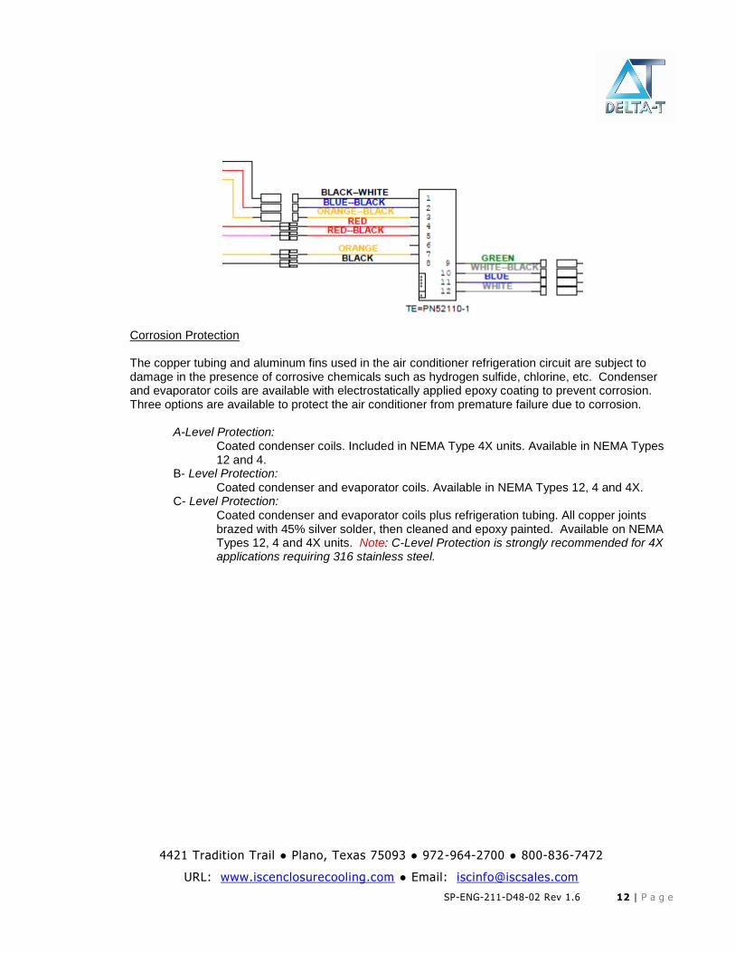
Open Door Kill Switch This option provides you with an adjustable and mountable safety switch for your electronics enclosure. This switch will disable power to the air conditioner when your electronics enclosure door is open allowing you to work on your enclosure without the risk of unintentionally powering the unit. Adjustable Temperature Probe The adjustable temperature probe provides you with a 12’ temperature probe that can be installed anywhere in your enclosure. This allows you to have the flexibility to monitor and maintain the temperature at any specific location of your enclosure. Ethernet/IP Controller Output This option provides the ability to communicate with the Delta-T Air Conditioner controller via the Ethernet/IP protocol. You can monitor and control all settings from a remote location with a PLC. Full specifications will be provided with this option. For full details refer to the Ethernet/IP Option Specifications included with the Air Conditioner. Remote Controller Option When having our Programmable Digital Controller on the face of our Air Conditioner does not fit your application, ISC Inc offers the Remote Controller Package (i.e. OD Option). This option moves the controller into your enclosure using a 10’ cable along with a universal, 16 gauge powder coated steel mounting bracket. The Air Conditioner will have no openings on the face of the unit. Below is a partial schematic showing the OD option wiring connections to the digital controller.
4421 Tradition Trail ● Plano, Texas 75093 ● 972-964-2700 ● 800-836-7472
URL: www.iscenclosurecooling.com ● Email: [email protected]
SP-ENG-211-D48-02 Rev 1.6 12 | P a g e
Corrosion Protection The copper tubing and aluminum fins used in the air conditioner refrigeration circuit are subject to damage in the presence of corrosive chemicals such as hydrogen sulfide, chlorine, etc. Condenser and evaporator coils are available with electrostatically applied epoxy coating to prevent corrosion. Three options are available to protect the air conditioner from premature failure due to corrosion. A-Level Protection: Coated condenser coils. Included in NEMA Type 4X units. Available in NEMA Types
12 and 4. B- Level Protection: Coated condenser and evaporator coils. Available in NEMA Types 12, 4 and 4X. C- Level Protection: Coated condenser and evaporator coils plus refrigeration tubing. All copper joints
brazed with 45% silver solder, then cleaned and epoxy painted. Available on NEMA Types 12, 4 and 4X units. Note: C-Level Protection is strongly recommended for 4X applications requiring 316 stainless steel.
4421 Tradition Trail ● Plano, Texas 75093 ● 972-964-2700 ● 800-836-7472
URL: www.iscenclosurecooling.com ● Email: [email protected]
SP-ENG-211-D48-02 Rev 1.6 13 | P a g e
System Faults
If any of the critical control parameters exceed limits, the compressor is turned off and an alarm condition is indicated on the front panel. There are three main conditions that can shut the AC compressor down:
The condenser high temperature alarm
The evaporator coil alarm
The compressor thermal overload
In the event that the condenser coil overheats, a condenser high temperature alarm, HA2, will flash on the display of the digital temperature controller and the compressor will turn off after a 3 minute time delay. In the case that the evaporator coil ices up or there is a leak, an evaporator coil alarm, CA, will flash on the display of the digital temperature controller and the compressor will turn off after a 2 minute time delay. A thermal overload protects the compressor against faults. In the event that the snowflake status LED is not flashing on the display and the compressor is not running, an internal fault may have occurred on the unit. Refer to the Troubleshooting Guide in this manual.
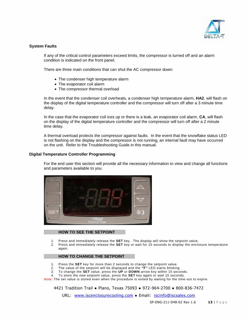
Digital Temperature Controller Programming
For the end user this section will provide all the necessary information to view and change all functions and parameters available to you.
HOW TO SEE THE SETPOINT……..
1. Press and immediately release the SET key. The display will show the setpoint value. 2. Press and immediately release the SET key or wait for 15 seconds to display the enclosure temperature
again.
HOW TO CHANGE THE SETPOINT……..
1. Press the SET key for more than 2 seconds to change the setpoint value. 2. The value of the setpoint will be displayed and the “F” LED starts blinking. 3. To change the SET value, press the UP or DOWN arrow key within 15 seconds. 4. To store the new setpoint value, press the SET key again or wait 15 seconds.
Note: The set value is stored even when the procedure is exited by waiting for the time -out to expire.
4421 Tradition Trail ● Plano, Texas 75093 ● 972-964-2700 ● 800-836-7472
URL: www.iscenclosurecooling.com ● Email: [email protected]
SP-ENG-211-D48-02 Rev 1.6 14 | P a g e
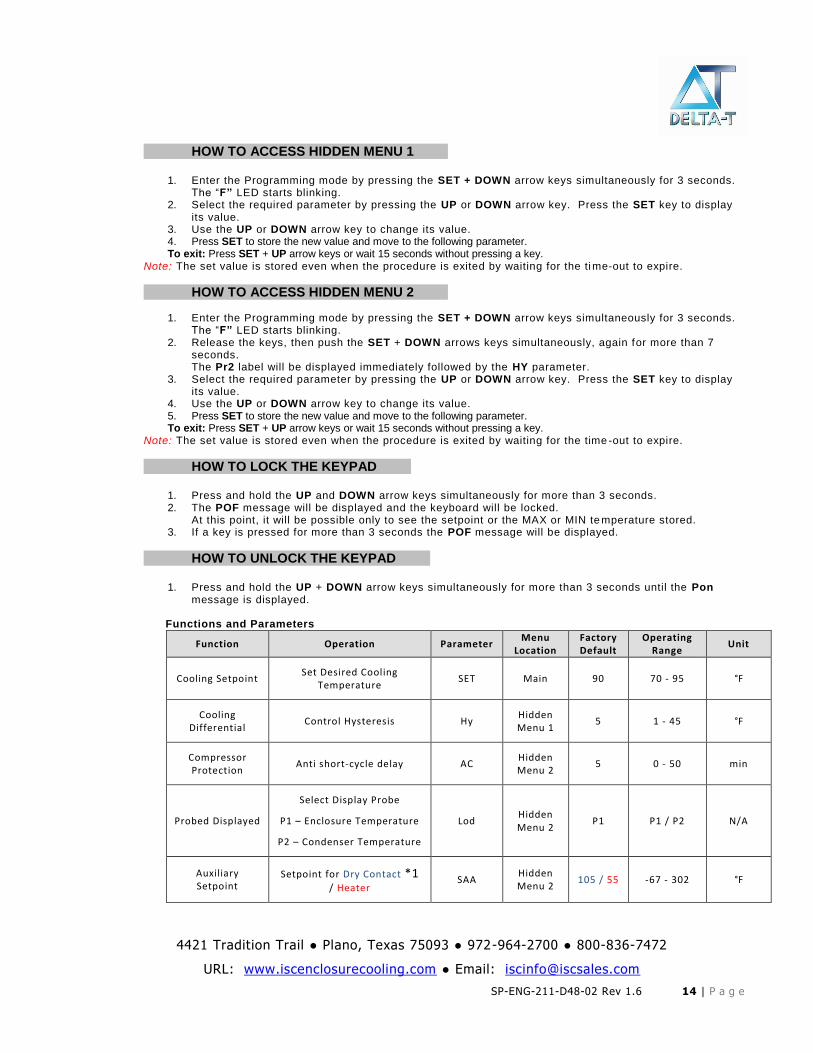
HOW TO ACCESS HIDDEN MENU 1……..
1. Enter the Programming mode by pressing the SET + DOWN arrow keys simultaneously for 3 seconds. The “F” LED starts blinking.
2. Select the required parameter by pressing the UP or DOWN arrow key. Press the SET key to display its value.
3. Use the UP or DOWN arrow key to change its value. 4. Press SET to store the new value and move to the following parameter. To exit: Press SET + UP arrow keys or wait 15 seconds without pressing a key.
Note: The set value is stored even when the procedure is exited by waiting for the time-out to expire.
HOW TO ACCESS HIDDEN MENU 2……..
1. Enter the Programming mode by pressing the SET + DOWN arrow keys simultaneously for 3 seconds. The “F” LED starts blinking.
2. Release the keys, then push the SET + DOWN arrows keys simultaneously, again for more than 7 seconds. The Pr2 label will be displayed immediately followed by the HY parameter.
3. Select the required parameter by pressing the UP or DOWN arrow key. Press the SET key to display its value.
4. Use the UP or DOWN arrow key to change its value. 5. Press SET to store the new value and move to the following parameter. To exit: Press SET + UP arrow keys or wait 15 seconds without pressing a key.
Note: The set value is stored even when the procedure is exited by waiting for the time -out to expire.
HOW TO LOCK THE KEYPAD……..
1. Press and hold the UP and DOWN arrow keys simultaneously for more than 3 seconds. 2. The POF message will be displayed and the keyboard will be locked.
At this point, it will be possible only to see the setpoint or the MAX or MIN te mperature stored. 3. If a key is pressed for more than 3 seconds the POF message will be displayed.
HOW TO UNLOCK THE KEYPAD……..
1. Press and hold the UP + DOWN arrow keys simultaneously for more than 3 seconds until the Pon message is displayed.
Functions and Parameters
Function Operation Parameter Menu
Location Factory Default
Operating Range
Unit
Cooling Setpoint Set Desired Cooling
Temperature SET Main 90 70 - 95 °F
Cooling Differential
Control Hysteresis Hy Hidden Menu 1
5 1 - 45 °F
Compressor Protection
Anti short-cycle delay AC Hidden Menu 2
5 0 - 50 min
Probed Displayed
Select Display Probe
P1 – Enclosure Temperature
P2 – Condenser Temperature
Lod Hidden Menu 2
P1 P1 / P2 N/A
Auxiliary Setpoint
Setpoint for Dry Contact *1 / Heater
SAA Hidden Menu 2
105 / 55 -67 - 302 °F
4421 Tradition Trail ● Plano, Texas 75093 ● 972-964-2700 ● 800-836-7472
URL: www.iscenclosurecooling.com ● Email: [email protected]
SP-ENG-211-D48-02 Rev 1.6 15 | P a g e
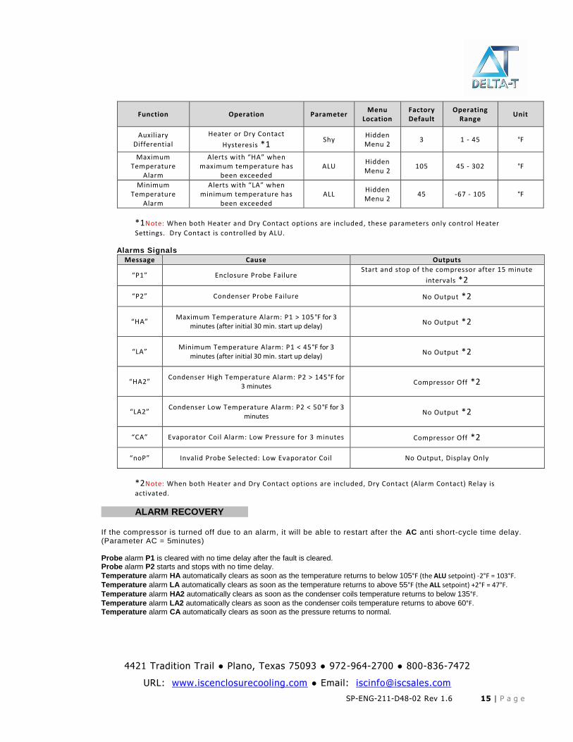
Function Operation Parameter Menu
Location Factory Default
Operating Range
Unit
Auxiliary Differential
Heater or Dry Contact
Hysteresis *1 Shy
Hidden Menu 2
3 1 - 45 °F
Maximum Temperature
Alarm
Alerts with “HA” when maximum temperature has
been exceeded ALU
Hidden Menu 2
105 45 - 302 °F
Minimum Temperature
Alarm
Alerts with “LA” when minimum temperature has
been exceeded ALL
Hidden Menu 2
45 -67 - 105 °F
*1Note: When both Heater and Dry Contact options are included, these parameters only control Heater
Settings. Dry Contact is controlled by ALU. Alarms Signals
Message Cause Outputs
“P1” Enclosure Probe Failure Start and stop of the compressor after 15 minute
intervals *2
“P2” Condenser Probe Failure No Output *2
“HA” Maximum Temperature Alarm: P1 > 105°F for 3
minutes (after initial 30 min. start up delay) No Output *2
“LA” Minimum Temperature Alarm: P1 < 45°F for 3
minutes (after initial 30 min. start up delay) No Output *2
“HA2” Condenser High Temperature Alarm: P2 > 145°F for
3 minutes Compressor Off *2
“LA2” Condenser Low Temperature Alarm: P2 < 50°F for 3
minutes No Output *2
“CA” Evaporator Coil Alarm: Low Pressure for 3 minutes Compressor Off *2
“noP” Invalid Probe Selected: Low Evaporator Coil No Output, Display Only
*2Note: When both Heater and Dry Contact options are included, Dry Contact (Alarm Contact) Relay is
activated.
ALARM RECOVERY…….. If the compressor is turned off due to an alarm, it will be able to restart after the AC anti short-cycle time delay. (Parameter AC = 5minutes)
Probe alarm P1 is cleared with no time delay after the fault is cleared. Probe alarm P2 starts and stops with no time delay.
Temperature alarm HA automatically clears as soon as the temperature returns to below 105°F (the ALU setpoint) -2°F = 103°F. Temperature alarm LA automatically clears as soon as the temperature returns to above 55°F (the ALL setpoint) +2°F = 47°F. Temperature alarm HA2 automatically clears as soon as the condenser coils temperature returns to below 135°F. Temperature alarm LA2 automatically clears as soon as the condenser coils temperature returns to above 60°F. Temperature alarm CA automatically clears as soon as the pressure returns to normal.
4421 Tradition Trail ● Plano, Texas 75093 ● 972-964-2700 ● 800-836-7472
URL: www.iscenclosurecooling.com ● Email: [email protected]
SP-ENG-211-D48-02 Rev 1.6 16 | P a g e
Preventative Maintenance
Air conditioners may require regular cleaning of the condenser air inlet section. Restriction to the flow of air over the condenser coil will degrade the performance of the equipment, cause it to overheat, reduce cooling and can damage the compressor. The overload switch in the compressor may cause the compressor to cycle if the condensing coil pressure becomes too high due to air restriction. A further safety feature is the refrigerant high pressure cut off switch which will stop the compressor if the condensing pressure becomes too high due restricted condenser air flow or some other cause.
Restricted air flow due to neglecting preventative maintenance will cause unit to repeatedly turn off and then turn back on after it cools off. An operation in this safety cycling mode will eventually damage the equipment and void the warranty.
Refer to Field Serviceable Parts section in this manual for details on parts that can be changed to help increase the uninterruptable life of the Air Conditioner.
Condenser and Evaporator Fans ISC Inc air conditioners use high efficiency, long life, sealed ball bearing fans engineered for optimum performance that require no maintenance. Keep fan blades clean for optimal performance. Fans are removable and attached by plug-in connections. Compressor ISC Inc uses hermetically factory sealed compressors that are quiet, low vibration and are maintenance free. Thermal overload devices are installed to protect the compressor from damage due to overheat and short cycle faults. If the compressor thermal overload fails, it is recommended to return the unit to ISC Inc customer service for proper replacement. Note that the rotary compressor runs with compressed refrigerant gas on the outer case and therefore is hot to the touch. Loss of Refrigerant ISC Inc air conditioners are meticulously leak and run tested after assembly. If a leak in the system should develop due to shipping damage or mechanical vibration, the leak must be detected, repaired and the refrigerant charge restored to the system by a qualified refrigeration professional.
Condenser Coils Depending on the environment the condenser coils may become dirty and the air conditioner may lose efficiency, causing overheating and diminished cooling capacity. Dirty condensing coils must be back-flush cleaned using proper commercial coils cleaning compounds and thorough back-flushing rinsing. Refer to directions on the cleaning compounds selected. Acid wash is not recommended as it reduces the life of the coil.
4421 Tradition Trail ● Plano, Texas 75093 ● 972-964-2700 ● 800-836-7472
URL: www.iscenclosurecooling.com ● Email: [email protected]
SP-ENG-211-D48-02 Rev 1.6 17 | P a g e
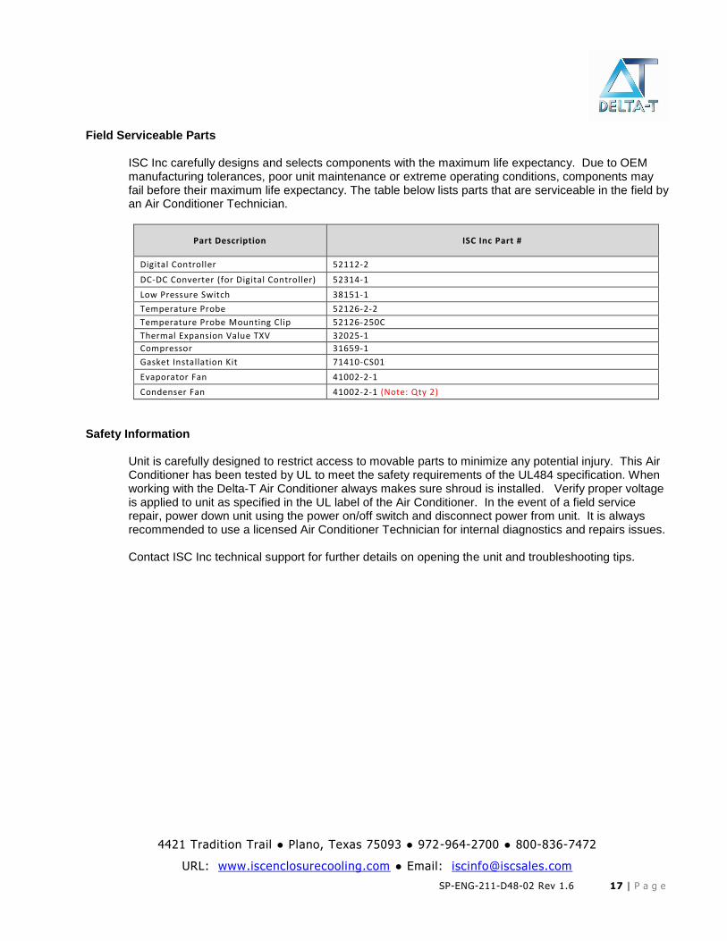
Field Serviceable Parts
ISC Inc carefully designs and selects components with the maximum life expectancy. Due to OEM manufacturing tolerances, poor unit maintenance or extreme operating conditions, components may fail before their maximum life expectancy. The table below lists parts that are serviceable in the field by an Air Conditioner Technician.
Part Description ISC Inc Part #
Digital Controller 52112-2
DC-DC Converter (for Digital Controller) 52314-1
Low Pressure Switch 38151-1
Temperature Probe 52126-2-2
Temperature Probe Mounting Clip 52126-250C
Thermal Expansion Value TXV 32025-1
Compressor 31659-1
Gasket Installation Kit 71410-CS01
Evaporator Fan 41002-2-1
Condenser Fan 41002-2-1 (Note: Qty 2)
Safety Information
Unit is carefully designed to restrict access to movable parts to minimize any potential injury. This Air Conditioner has been tested by UL to meet the safety requirements of the UL484 specification. When working with the Delta-T Air Conditioner always makes sure shroud is installed. Verify proper voltage is applied to unit as specified in the UL label of the Air Conditioner. In the event of a field service repair, power down unit using the power on/off switch and disconnect power from unit. It is always recommended to use a licensed Air Conditioner Technician for internal diagnostics and repairs issues. Contact ISC Inc technical support for further details on opening the unit and troubleshooting tips.
4421 Tradition Trail ● Plano, Texas 75093 ● 972-964-2700 ● 800-836-7472
URL: www.iscenclosurecooling.com ● Email: [email protected]
SP-ENG-211-D48-02 Rev 1.6 18 | P a g e
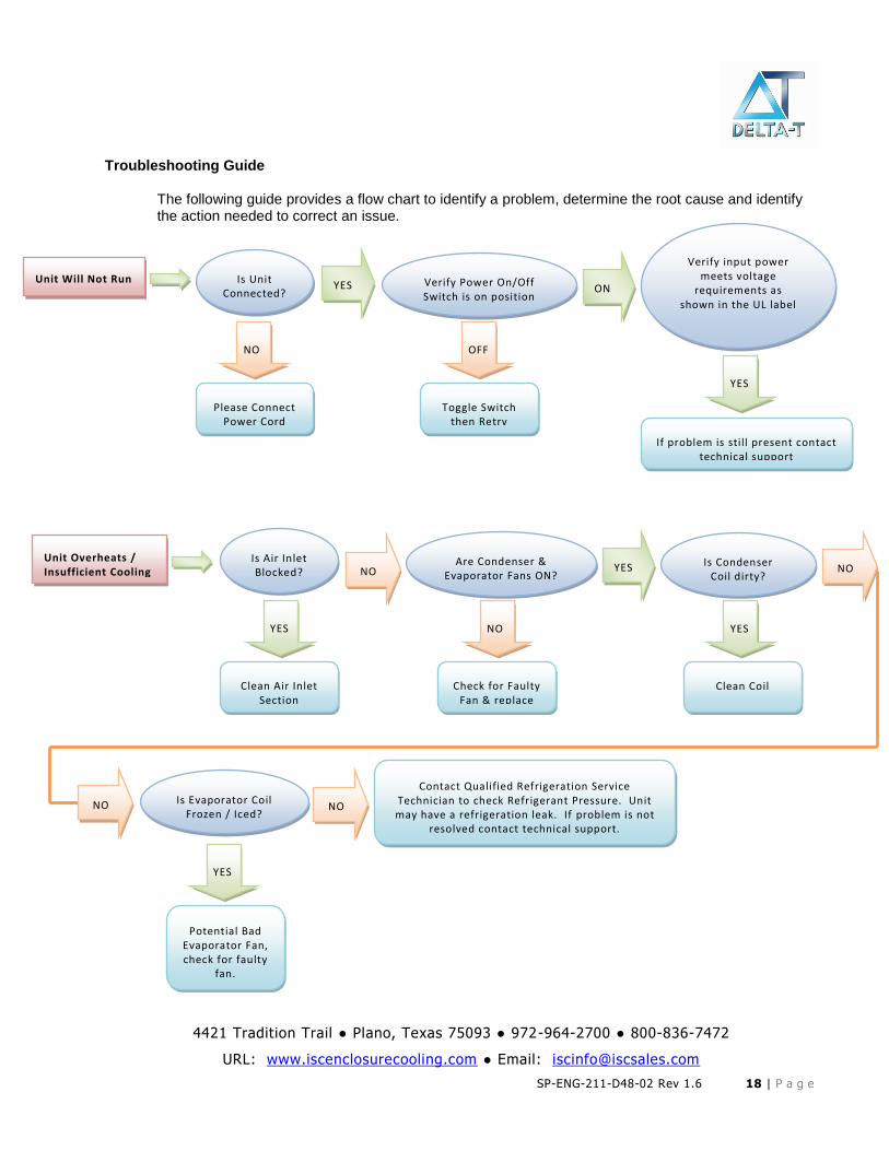
Troubleshooting Guide
The following guide provides a flow chart to identify a problem, determine the root cause and identify the action needed to correct an issue.
Unit Will Not Run Is Unit Connected?
YES
NO
Please Connect Power Cord
Verify Power On/Off Switch is on position
ON
OFF
Toggle Switch then Retry
Verify input power meets voltage
requirements as shown in the UL label
YES
If problem is still present contact technical support
Unit Overheats / Insufficient Cooling
Is Air Inlet Blocked?
Clean Air Inlet Section
Are Condenser & Evaporator Fans ON?
NO
Check for Faulty Fan & replace
YES Is Condenser Coil dirty?
YES
Clean Coil
NO
NO Is Evaporator Coil Frozen / Iced?
YES
Potential Bad Evaporator Fan, check for faulty
fan.
NO
Contact Qualified Refrigeration Service Technician to check Refrigerant Pressure. Unit may have a refrigeration leak. If problem is not
resolved contact technical support.
NO
YES
4421 Tradition Trail ● Plano, Texas 75093 ● 972-964-2700 ● 800-836-7472
URL: www.iscenclosurecooling.com ● Email: [email protected]
SP-ENG-211-D48-02 Rev 1.6 19 | P a g e
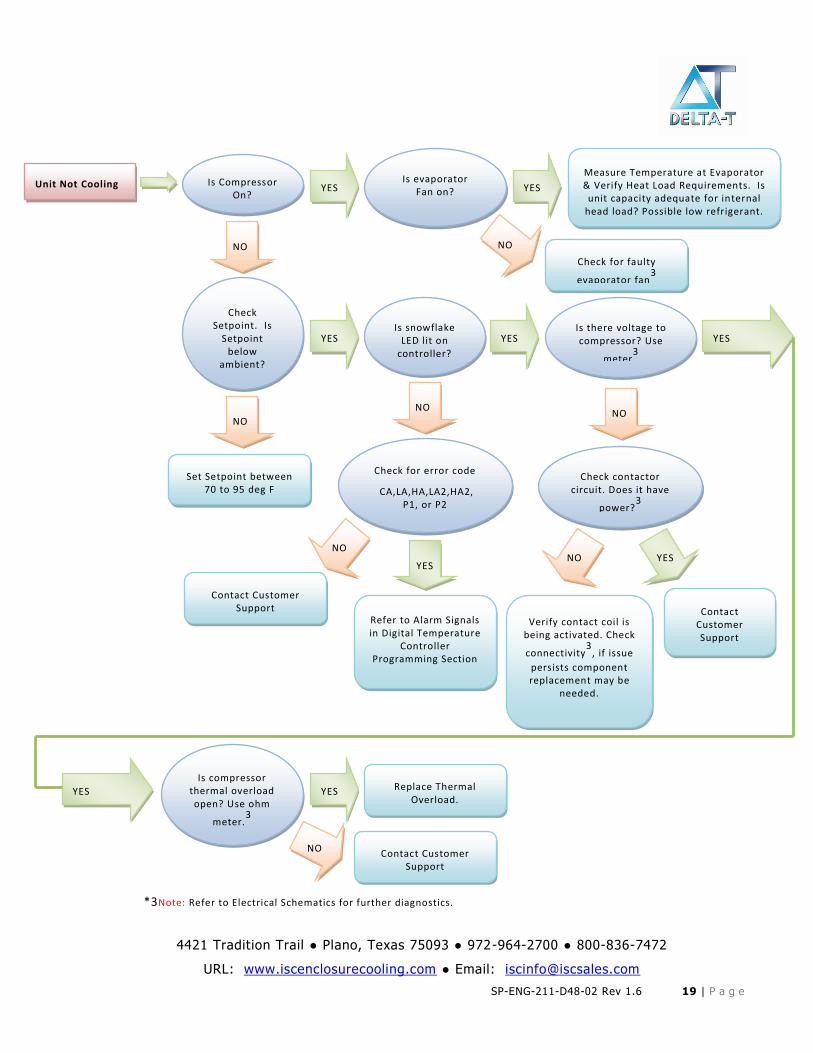
*3Note: Refer to Electrical Schematics for further diagnostics.
Unit Not Cooling Is Compressor On?
YES
NO
Check Setpoint. Is
Setpoint below
ambient?
YES
NO
Is snowflake LED lit on
controller?
Set Setpoint between 70 to 95 deg F
YES
NO
Is evaporator Fan on? YES
NO
Is there voltage to compressor? Use
meter3
Check for faulty
evaporator fan3
Measure Temperature at Evaporator & Verify Heat Load Requirements. Is
unit capacity adequate for internal head load? Possible low refrigerant.
Is compressor thermal overload open? Use ohm
meter.3
Check for error code
CA,LA,HA,LA2,HA2, P1, or P2
YES
NO
Check contactor circuit. Does it have
power?3
NO
YES
Refer to Alarm Signals in Digital Temperature
Controller Programming Section
Contact Customer Support
NO YES
Verify contact coil is being activated. Check
connectivity3
, if issue
persists component replacement may be
needed.
Contact Customer Support
YES
NO
YES
Contact Customer Support
Replace Thermal Overload.
4421 Tradition Trail ● Plano, Texas 75093 ● 972-964-2700 ● 800-836-7472
URL: www.iscenclosurecooling.com ● Email: [email protected]
SP-ENG-211-D48-02 Rev 1.6 20 | P a g e
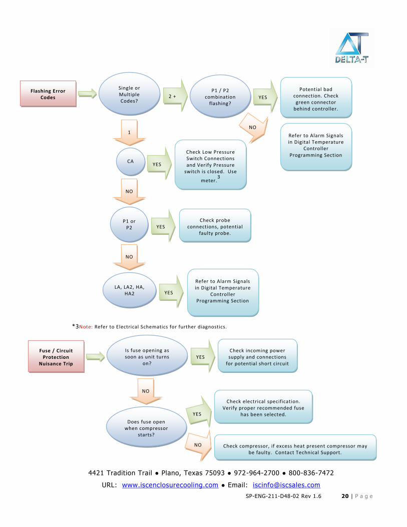
*3Note: Refer to Electrical Schematics for further diagnostics.
Flashing Error Codes
Single or Multiple Codes?
2 +
1 Refer to Alarm Signals in Digital Temperature
Controller Programming Section
P1 / P2 combination
flashing? YES
NO
Potential bad connection. Check green connector
behind controller.
CA YES
NO
Check Low Pressure Switch Connections and Verify Pressure
switch is closed. Use
meter.3
P1 or P2
NO
YES Check probe
connections, potential faulty probe.
LA, LA2, HA, HA2 YES
Refer to Alarm Signals in Digital Temperature
Controller Programming Section
Fuse / Circuit Protection
Nuisance Trip
Is fuse opening as soon as unit turns
on?
NO
YES Check incoming power supply and connections
for potential short circuit
Does fuse open when compressor
starts?
YES
NO
Check electrical specification. Verify proper recommended fuse
has been selected.
Check compressor, if excess heat present compressor may be faulty. Contact Technical Support.
4421 Tradition Trail ● Plano, Texas 75093 ● 972-964-2700 ● 800-836-7472
URL: www.iscenclosurecooling.com ● Email: [email protected]
SP-ENG-211-D48-02 Rev 1.6 21 | P a g e
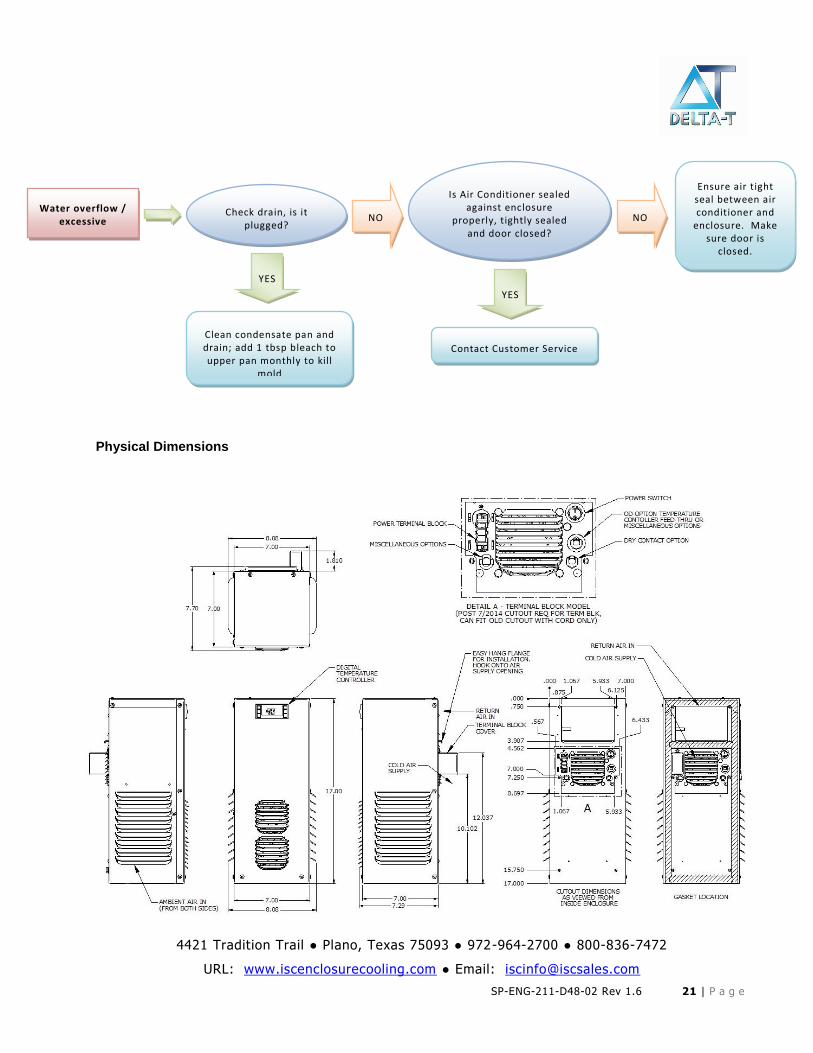
Physical Dimensions
Water overflow / excessive
Check drain, is it plugged?
YES
NO
Clean condensate pan and drain; add 1 tbsp bleach to upper pan monthly to kill
mold
Is Air Conditioner sealed against enclosure
properly, tightly sealed and door closed?
YES
Contact Customer Service
NO
Ensure air tight seal between air conditioner and
enclosure. Make sure door is
closed.
4421 Tradition Trail ● Plano, Texas 75093 ● 972-964-2700 ● 800-836-7472
URL: www.iscenclosurecooling.com ● Email: [email protected]
SP-ENG-211-D48-02 Rev 1.6 22 | P a g e
THIS PAGE IS INTENTIONALLY LEFT BLANK
4421 Tradition Trail ● Plano, Texas 75093 ● 972-964-2700 ● 800-836-7472
URL: www.iscenclosurecooling.com ● Email: [email protected]
SP-ENG-211-D48-02 Rev 1.6 23 | P a g e
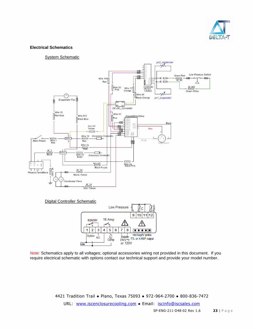
Electrical Schematics System Schematic
Digital Controller Schematic
Note: Schematics apply to all voltages; optional accessories wiring not provided in this document. If you require electrical schematic with options contact our technical support and provide your model number.
4421 Tradition Trail ● Plano, Texas 75093 ● 972-964-2700 ● 800-836-7472
URL: www.iscenclosurecooling.com ● Email: [email protected]
SP-ENG-211-D48-02 Rev 1.6 24 | P a g e
Warranty Information
ISC Inc products are warranted to be free of defects in workmanship, materials and components. The warranty period applies from date of shipment for one year. Replacement components have a one year warranty period, except for hermetic system components, which have a 90 day warranty period.
The above warranty applies when the equipment is operated under the following conditions:
Ambient temperature not in excess of performance rating in normal atmosphere or as sta ted on product nameplate
Voltage variation no greater than ± 10% from nameplate rating
Maximum cooling load no higher than air conditioner nameplate rating
Waiting five minutes before restarting air conditioner after intentional or accidental shutoff
Compliance to all other installation, maintenance and operating instructions, as supplied
ISC Inc cannot assume responsibility for misapplication of its products or the erroneous selection of an inappropriate product by a non-authorized ISC Inc representative. Our applications engineers will gladly assist in the selection of the proper product provided all required details of the application are furnished.
ISC Inc assumes no liability beyond the repair or replacement of its own product. This Warranty does not cover:
Labor or reimbursement of labor for evaluation, removal, installation, repair, or cost of any warranted part, except at the ISC Inc factory in Dallas, Texas
Use of equipment for other than its designed purpose or operating conditions
Operation in harsh, oily, corrosive or other abnormal environmental conditions, without the proper filtration, sealing, protective coatings and/or weather protection
Damage to hermetic system resulting from continuous operation with dirty or clogged air filters or improper or negligent maintenance
Use of refrigerant other than designated
Customer modification or abuse
Shipping damage or other accident
Repair or service by unauthorized personnel.
Cracked or broken hermetic tubing or brazed joints caused by shipping damage or mishandling are not covered under the Warranty. Claims for shipping damage are the responsibility of the Consignee. Timely claims must be filed with the freight carrier.
The purchaser assumes the responsibility of grounding the unit and installing it in accordance with local electrical and safety codes, as well as the 2008 National Electric Code (NEC) and OSHA.
THIS WARRANTY CONSTITUTES THE ENTIRE WARRANTY WITH RESPECT TO THE PRODUCT AND IS IN LIEU OF ALL OTHERS, EXPRESSED OR IMPLIED, INCLUDING ANY WARRANTY OF MERCHANTABILITY AND WARRANTY OF FITNESS FOR A PARTICULAR PURPOSE AND IN NO EVENT IS ISC INC RESPONSIBLE FOR ANY CONSEQUENTIAL DAMAGES OF ANY NATURE WHATSOEVER.
4421 Tradition Trail ● Plano, Texas 75093 ● 972-964-2700 ● 800-836-7472
URL: www.iscenclosurecooling.com ● Email: [email protected]
SP-ENG-211-D48-02 Rev 1.6 25 | P a g e
Return Material Authorization (RMA) Procedure
All returns require a Return Material Authorization (RMA) number for warranty or non-warranty repair, rotation of stock, damage or any other reason.
IMPORTANT Returns without an RMA number will be refused and returned. Improper packaging may void warranty. Air Conditioners shipped laying down will void the warranty. Collect shipments will be refused.
Please be ready to provide:
Purchase Order Number & Date
Product Description & Reason for Request
Model Number & Serial Number
Customer name and contact info (email, phone number and address)
Shipping method
Pack unit in a suitable packing for shipment, preferably the original packaging if available.
If suitable packing is not available, arrange for packaging to be shipped to you.
Air Conditioners must be returned in an upright position properly secured to a pallet.
Tip unit to empty water from the evaporator and boil off pans.
Clearly mark the RMA number on the box.
Customer will pay all freight charges.
Out of Warranty Repair
If your ISC Inc air conditioner is out of warranty and requires repair, simply call ISC Inc Customer Service at (800)-836-7472 for an RMA number. Customer Service will help you determine what repairs or parts are needed and, if possible, an estimate of the cost.
After the unit is received and diagnosed, you will receive an estimate on the work and parts needed. The repairs and test process may uncover other issues of which you will be informed and given quotes for the work needed.
4421 Tradition Trail ● Plano, Texas 75093 ● 972-964-2700 ● 800-836-7472
URL: www.iscenclosurecooling.com ● Email: [email protected]
SP-ENG-211-D48-02 Rev 1.6 26 | P a g e
Appendix A
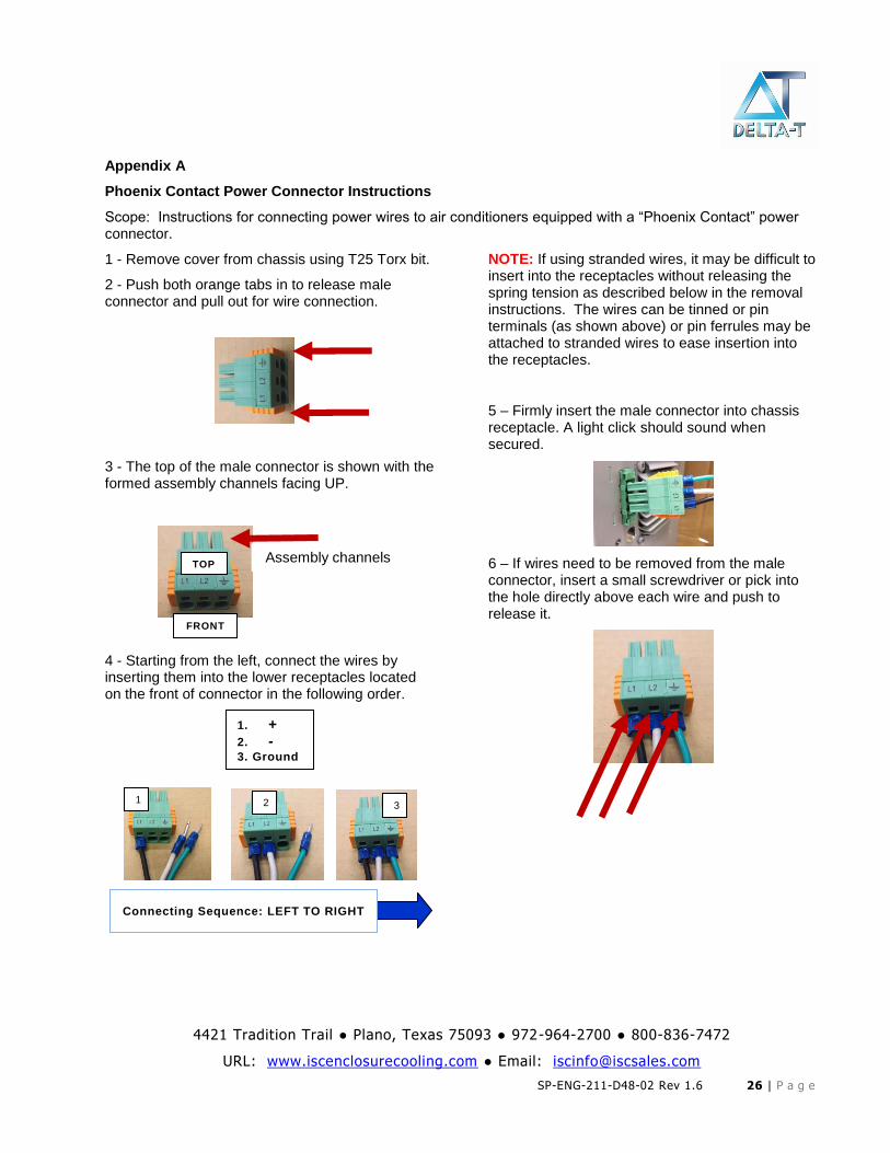
Phoenix Contact Power Connector Instructions
Scope: Instructions for connecting power wires to air conditioners equipped with a “Phoenix Contact” power connector.
1 - Remove cover from chassis using T25 Torx bit.
2 - Push both orange tabs in to release male connector and pull out for wire connection.
3 - The top of the male connector is shown with the formed assembly channels facing UP.
4 - Starting from the left, connect the wires by inserting them into the lower receptacles located on the front of connector in the following order.
NOTE: If using stranded wires, it may be difficult to insert into the receptacles without releasing the spring tension as described below in the removal instructions. The wires can be tinned or pin terminals (as shown above) or pin ferrules may be attached to stranded wires to ease insertion into the receptacles.
5 – Firmly insert the male connector into chassis receptacle. A light click should sound when secured.
6 – If wires need to be removed from the male connector, insert a small screwdriver or pick into the hole directly above each wire and push to release it.
Assembly channels
1. +
2. -
3. Ground
TOP
FRONT
Connecting Sequence: LEFT TO RIGHT
1
2
3