Embed Size (px)
Citation preview
Wireless NVR System User Manual
1
User Manual
xmartO Wireless NVR System Ver. 1.4
Wireless NVR System User Manual
1
Preface
Thank you for purchasing xmartO products! This user manual is to introduce the operations of
xmartO wireless camera systems in more details. If there is any other question which is not covered in
this user manual, please contact xmartO support.
Statement
· Though we apply all efforts to make the manual complete and accurate, there could still be
some discrepancies due to products’ timely update.
· The products and manual are subject to change without previous notification.
· The content in this manual is only for users’ reference. We don’t promise it’s exactly the same
with the products you purchase. Detailed information is in accordance with the final products.
· The accessories and parts mentioned in this manual are only for product using guide purpose
and not necessarily to be included in your purchased item.
Special Statement
Please comply with local laws and regulations when you use the surveillance devices.
About default settings
·The default user account ID is super administrator ID: admin.
·The default password for account ‘admin’ is empty.
·The default IPv4 address of device is: 192.168.1.114
·The default setting of NVR is to overwrite earliest recorded videos when hard drive is
full.
·The device will start Setup Wizard by default when NVR is powered on.
Wireless NVR System User Manual
2
Content
Preface……………………………………………………………………………………………………………………………………………….1
CONTENT……………………………………………………………………………………………………………………………………………2
1. Product features overview……………………………………………………………………………………………………………4
1.1 Product introduction………………………………………………………………………………………………………………4
1.2 Product Specifications…………………………………………………………………………………………………………….4
1.3 Product Key Features……………………………………………………………………………………………………………...5
2. Operating instructions………………………………………………………………………………………………………………….6
2.1 Front panel………………………………………………………………………………………………………………………..…..6
2.2 Rear panel………………………………………………………………………………………………………………………………6
2.3 Mouse operation…………………………………………………………………………………………………………………...7
2.4 Input method…………………………………………………………………………………………………………………………7
2.5 User Interface…………………………………………………………………………………………………………………………8
2.5.1 User Interface element…………………………………………………………………………………………………..8
2.5.2 Frequently-used buttons……………………………………………………………………………………………..…8
2.6 Menu Introduction……………………………………………………………………………………………………………….…8
3. Installation and connection…………………………………………………………………………………………………….…….8
3.1 Installation precautions………………………………………………………………………………………………….….…..8
3.2 Install hard drive……………………………………………………………………………………………………………………..9
3.3 Preparations before installation………………………………………………………………………………………………9
3.4 Camera mounting spots…………………………………………………………………….………………………………….10
3.5 Antenna mounting tips………………..……………………….……………………………………………………..……….10
4. Operation system introduction…………………………………………………………………………………………………..11
4.1 Starting up/ log in/ log out/ restart…………………………………………………………………………………..…..11
4.1.1 Starting up…………………………………………………………………………………………………………………...11
4.1.2 Login………………………………………………………………………………………………………………………….…12
4.1.3 Logout…………………………………………………………………………………………………………………….……12
4.1.4 System restart………………………………………………………………………………………………………….…..13
4.2 Setup Wizard………………………………………………………………………………………..………………….…………..13
4.3 Video management……………………………………………………………………………………………………………...15
4.3.1 Search device……………………………………..…………………………………………………………………….….15
4.3.2 Add device……………………………………………………………………………………………………………..…….16
4.3.3 Delete device……………………………………………………………………………………………………..………..18
4.3.4 Edit channel………………………………………………………………………………………………………………….18
4.3.5 Stream setting……………………………………………………………………………………………………………..19
4.4 Network setting…………………………………………………………………………………………………………….………20
4.4.1 Network settings……………………………………………………………………………………………………..…..20
4.4.2 Dynamic domain name server (DDNS)…………………………………………………………………….……21
4.4.3 FTP……………………………………………………………………………………………………………………….………21
4.4.4 Email………………………………………………………………………………………………………………………..….22
4.4.5 PPPoE…………………………………………………………………………………………………………………………..23
4.4.6 3G…………………………………………………………………………………………………………………………..……24
4.4.7 Wireless (Wi-Fi) settings………………………………………………………………………………………………25
4.5 Pan & Tilt setting………………………………………………………………………………………………………………….26
4.5.1 Pan & Tilt parameter setting………………………………………………………………………………………..26
4.5.2 Pan & Tilt control…………………………………………………………………………………………………..…….26

Wireless NVR System User Manual
3
4.5.3 Pan & Tilt auto cruise setting…………………………………………………………………………………….…27
4.6 Record………………………………………………………………………………………………………………………………….28
4.6.1 Manual record……………………………………………………………………………………………………….….…28
4.6.2 Time-scheduled record…………………………………………………………………………………………….….28
4.6.3 Motion detection record………………………………………………………………………………………………29
4.6.4 Alarm triggered record………………………………………………………………………………………………...30
4.7 Video playback……………………………………………………………………………………………………………………..31
4.7.1 Quick playback…………………………………………………………………………………………………………..…31
4.7.2 Regular playback……………………………………………………………………………………………………..…..31
4.8 Video backup……………………………………………………………………………………………………………..………..32
4.9 Alarm……………………………………………………………………………………………………………………………..…….34
4.9.1 Motion detection alarm………………………………………………………………………………………….……34
4.9.2 Video loss alarm…………………………………………………………………………………………………….…….35
4.10 General settings………………………………………………………………………………………………………………….35
4.10.1 General settings………………………………………………………………………………………………………35
4.10.2 Time settings………………………………………………………………………………………………………….36
4.10.3 Screen settings………………………………………………………………………………………………………..37
4.10.4 Hard drive settings…………………………………………………………………………………………….……38
4.11 Device maintenance and management………………………………………………………………………..……39
4.11.1 System information…………………………………………………………………………………………….…..39
4.11.2 User management…………………………………………………………………………………………………..41
4.11.3 Restore factory settings…………………………………………………………………………………………..44
4.11.4 System maintenance……………………………………………………………………………………………….45
5. Access system from webpage……………………………………………………………………………..……………………..46
5.1 Brief introduction………………………………………………………………………………….………………….…………..46
5.2 Access from LAN (local area network)…………………………………………………………………………….…….46
5.2.1 Login……………………………………………………………………………………………………………….….……….46
5.2.2 Live view……………………………………………………………………………………………………………………...48
5.2.3 Playback……………………………………………………………………………………………………………………….49
5.2.4 Configure…………………………………………………………………………………………………………..…………50
5.3 Access from remote PC……………………………………………………………………………………………….……..…50
5.3.1 Login e-seenet with device ID…………………………………………………………………….……………..…50
5.3.2 Login with user ID………………………………………………………………………………………………………..52
6. Access from smartphone………………………………………………………………………………………………………………52
7. Appendix………………………………………………………………………………………………………………………………….…..55
7.1 Hard drive capacity calculation……………………………………………………………………………………………….55
7.2 Recording capacity calculation………………………………………………………………………………………………..55
Tips: If you don’t find your answer here, please logon http://www.xmarto.com/support/ for FAQ; or
contact [email protected]
Wireless NVR System User Manual
4
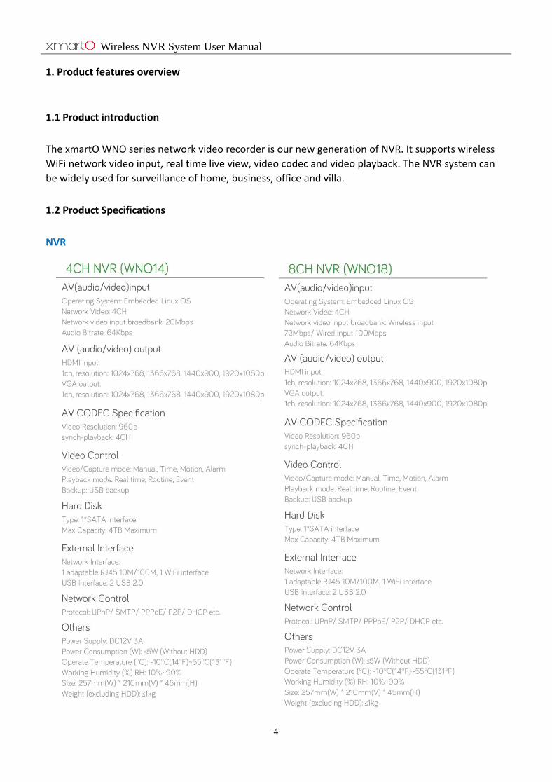
1. Product features overview
1.1 Product introduction
The xmartO WNO series network video recorder is our new generation of NVR. It supports wireless
WiFi network video input, real time live view, video codec and video playback. The NVR system can
be widely used for surveillance of home, business, office and villa.
1.2 Product Specifications
NVR
Wireless NVR System User Manual
5
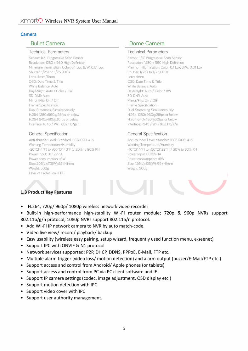
Camera
1.3 Product Key Features
• H.264, 720p/ 960p/ 1080p wireless network video recorder
• Built-in high-performance high-stability Wi-Fi router module; 720p & 960p NVRs support
802.11b/g/n protocol, 1080p NVRs support 802.11a/n protocol.
• Add Wi-Fi IP network camera to NVR by auto match-code.
• Video live view/ record/ playback/ backup
• Easy usability (wireless easy pairing, setup wizard, frequently used function menu, e-seenet)
• Support IPC with ONVIF & N1 protocol
• Network services supported: P2P, DHCP, DDNS, PPPoE, E-Mail, FTP etc.
• Multiple alarm trigger (video loss/ motion detection) and alarm output (buzzer/E-Mail/FTP etc.)
• Support access and control from Android/ Apple phones (or tablets)
• Support access and control from PC via PC client software and IE.
• Support IP camera settings (codec, image adjustment, OSD display etc.)
• Support motion detection with IPC
• Support video cover with IPC
• Support user authority management.

Wireless NVR System User Manual
6
2. Operation Instructions
2.1 Front Panel
Image 1
1. POWER:Power Indicator
2. HDD:Hard Drive Indicator
3. Operation Indicator – When IPC is connected to the NVR, this indicator will blink green
2.2 Rear Panel
Image 2
1. VGA: VGA Video Output
2. HDMI: HDMI Output
3. USB: USB Ports

Wireless NVR System User Manual
7
4. DC12V: Power Input
5. WAN: Connect your NVR to router for Internet connection
6. LAN1 – LAN3: IPC video inputs (only when necessary)
7. Wi-Fi Antenna connectors
2.3 Mouse Operations
Button Operation Effect Example
Left button Single click Choose object 1. Choose button, drop-down box, list box, check box
Double click Zoom window 1. Switch between multiple view mode and single view
mode
2. Add device Drag Set zone 1. Set motion detection zone
2. Choose digital zoom zone
Middle button Scroll Change contents 1. Change drop-down box content
2. Switch channels under single view mode
Right button Single click Exit 1. Exit the interface
2. Enter quick menu
2.4 Input Method
Image 3
Name Buttons Function
Number 0~9 Type in number 0~9
Character - / . _ * # @ Type in symbols
Caps caps Switch capital and small letter
Back space ← Delete the character ahead of cursor

Wireless NVR System User Manual
8
2.5 User Interface Introduction
2.5.1 User Interface Element Description
Name Operation Effect Example
Button Left click mouse Save or cancel Apply, confirm, cancel
Open sub interface Edit, setting
Edit box Left click mouse Edit Edit password
Drop-down box Left click mouse Select Choose language
List box Left click mouse View Channel information
Check box Left click mouse Select or cancel Setup wizard display, display e-seenet at preview
Text None Instructions Title, name
2.5.2 Frequently-used Button Description
Name Icon Explanation
Confirm
Save and apply operation, close window
Cancel
Cancel the operation
Apply
Save and apply operation, stay at the window
Copy to
Copy the settings of this channel to other or all channels
2.6 Menu Introduction
System setup: General setup, Record setup, Network setup, System Admin.
Right-click Menu: Split screen, Video playback, Video backup, PTZ control, Color adjust, Volume,
Manual record, System setup, Setup Wizard, IPC Add, Exit System.
3. Installation and Connection
3.1 Installation Precautions
Please refer to below tips while install and use the device:

Wireless NVR System User Manual
9
1. To extend the life of the device, please keep the device away from water, high temperature, and
dust. Use it in a well-ventilated place.
2. Please use SATA hard drive, USB devices and mouse purchased from authentic channels.
3. Before use, please ensure the NVR has correct ground connection. Power source should not exceed
the indicated normal working voltage range in the specs sheet.
3.2 Install Hard Drive
Image 4
3.3 Preparations before installation
1. Decide the location of NVR. It is suggested to place the NVR at the center of monitoring area. Avoid
any avoidable obstacle between the cameras and the NVR.
1) When there is no obstacle, cameras can be mounted about 60m away from the NVR (approx.
200ft);
2) When there is one wall in between, reduce the distance to 30m (approx. 100ft);
3) When there are 2 walls in between, reduce the distance to 15m (approx. 50ft);
4) When there are more than 2 walls between camera and NVR, we suggest using extendable
antennas to bring camera’s antenna inside walls while leaving camera out; or use network cable to
connect the camera to NVR.
* (The Wi-Fi range mentioned above vary in different environments; data only for reference)
Wireless NVR System User Manual
10
2. Test the system before installation. Connect the NVR to a monitor/ TV via VGA or HDMI, connect it
to power with included power adapter (bigger one is for NVR); mount antennas for cameras, connect
cameras to power. If you see images from all cameras within minutes, you can go ahead to mount the
cameras to where you want. If not, please follow step 4.3.2 to add the camera to system.
3.4 Camera Mounting Spots
1. Mount the cameras anywhere within the Wi-Fi range, connect them to power with included power
adapters (smaller ones are for cameras).
2. The cameras should start to stream videos to NVR within 1 minute.
3. If it does not display video on the NVR’s screen, the distance should be too long or there are too
many obstacles. Please move the cameras closer to the NVR.
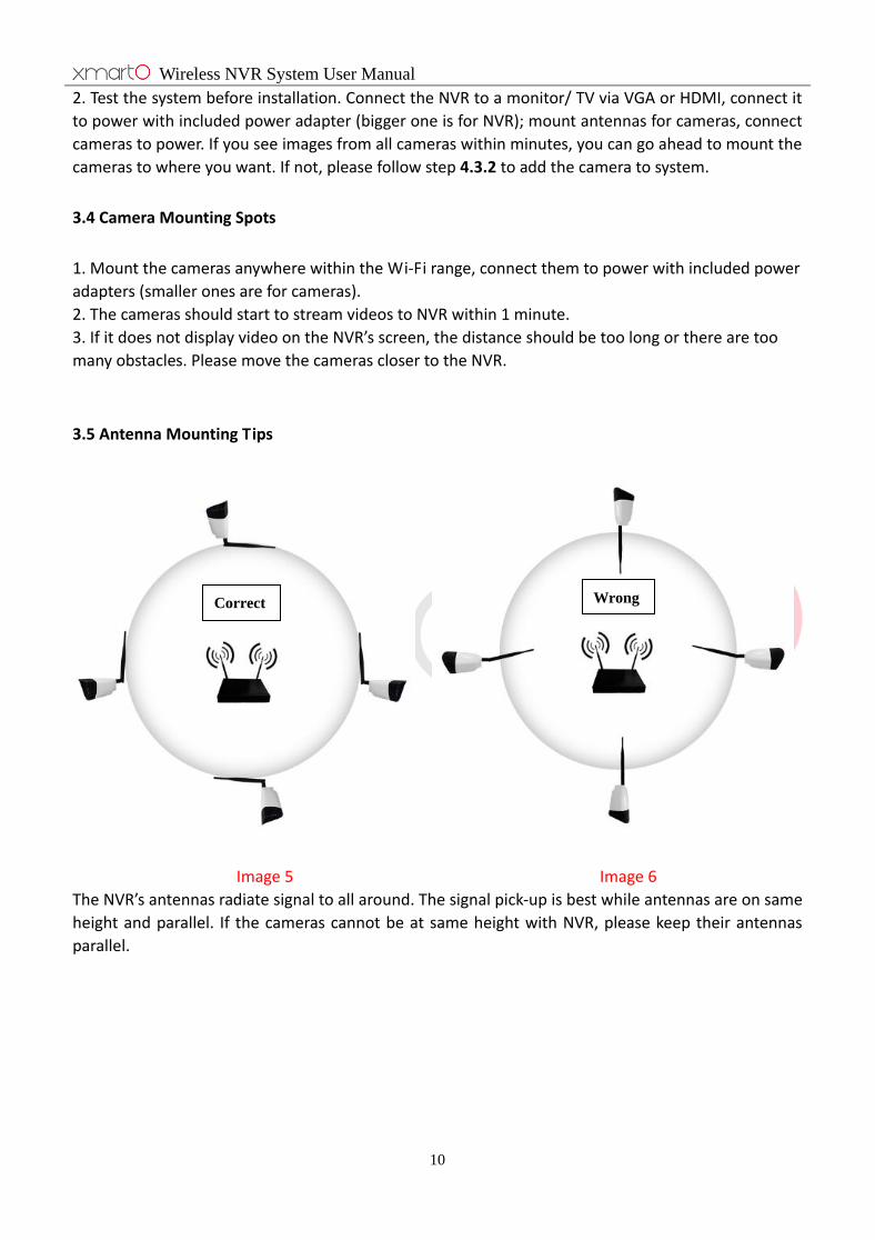
3.5 Antenna Mounting Tips
Image 5 Image 6
The NVR’s antennas radiate signal to all around. The signal pick-up is best while antennas are on same
height and parallel. If the cameras cannot be at same height with NVR, please keep their antennas
parallel.
Wrong Correct
Wireless NVR System User Manual
11
4. Operation system introduction
4.1 Starting up/ log in/ log out/ restart
4.1.1 Starting up
Note:
· Please ensure the input voltage fit the NVR’s requirements and the NVR has correct ground
connection.
· Unstable power source may cause unstable working status or even damage the NVR. If you have
unstable power source in your area, please use voltage-stabilized power source.
Tips:
· Before power on the NVR, please connect the NVR to a monitor or TV.
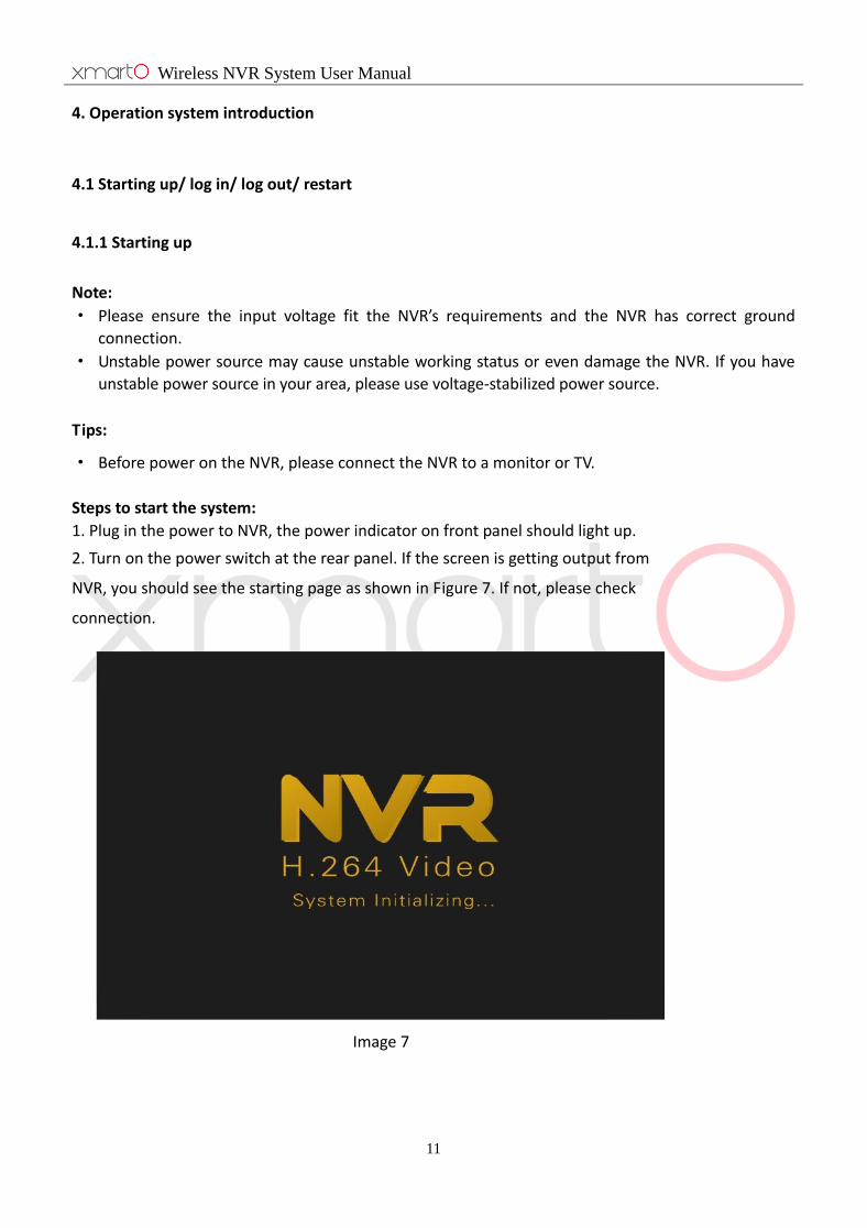
Steps to start the system:
1. Plug in the power to NVR, the power indicator on front panel should light up.
2. Turn on the power switch at the rear panel. If the screen is getting output from
NVR, you should see the starting page as shown in Figure 7. If not, please check
connection.
Image 7
Wireless NVR System User Manual
12
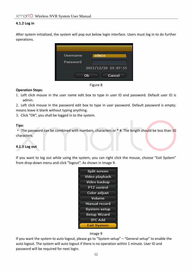
4.1.2 Log in
After system initialized, the system will pop out below login interface. Users must log in to do further
operations.
Figure 8
Operation Steps:
1. Left click mouse in the user name edit box to type in user ID and password. Default user ID is
admin.
2. Left click mouse in the password edit box to type in user password. Default password is empty;
means leave it blank without typing anything.
3. Click “OK”, you shall be logged in to the system.
Tips:
· The password can be combined with numbers, characters or * #. The length should be less than 10
characters.
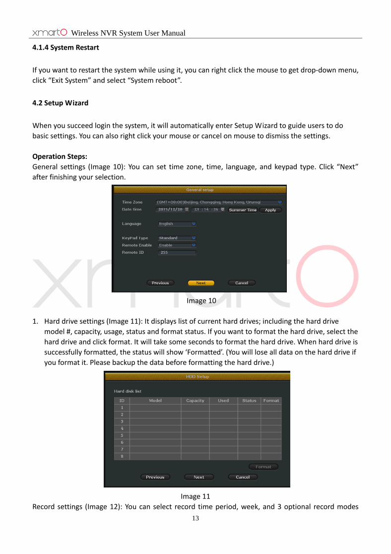
4.1.3 Log out
If you want to log out while using the system, you can right click the mouse, choose “Exit System”
from drop-down menu and click “logout”. As shown in Image 9.
Image 9
If you want the system to auto logout, please go to “System setup” – “General setup” to enable the
auto logout. The system will auto logout if there is no operation within 1 minute. User ID and
password will be required for next login.
Wireless NVR System User Manual
13
4.1.4 System Restart
If you want to restart the system while using it, you can right click the mouse to get drop-down menu,
click “Exit System” and select “System reboot”.
4.2 Setup Wizard
When you succeed login the system, it will automatically enter Setup Wizard to guide users to do
basic settings. You can also right click your mouse or cancel on mouse to dismiss the settings.
Operation Steps:
General settings (Image 10): You can set time zone, time, language, and keypad type. Click “Next”
after finishing your selection.
Image 10
1. Hard drive settings (Image 11): It displays list of current hard drives; including the hard drive
model #, capacity, usage, status and format status. If you want to format the hard drive, select the
hard drive and click format. It will take some seconds to format the hard drive. When hard drive is
successfully formatted, the status will show ‘Formatted’. (You will lose all data on the hard drive if
you format it. Please backup the data before formatting the hard drive.)
Image 11
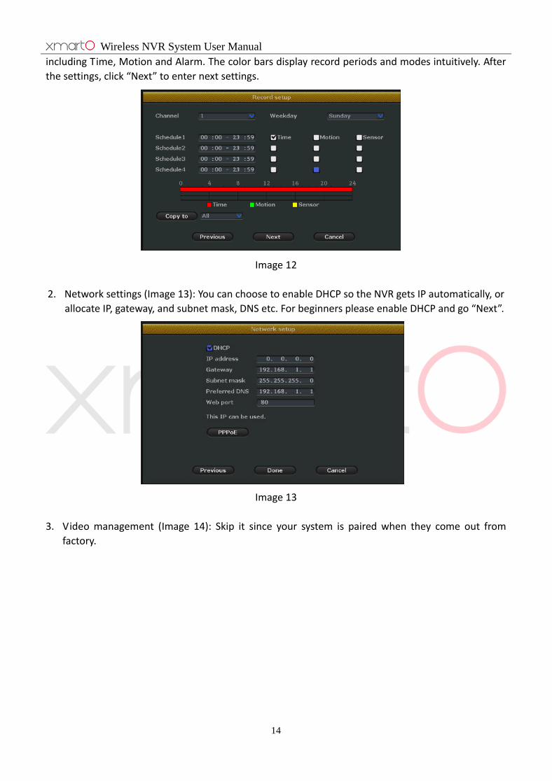
Record settings (Image 12): You can select record time period, week, and 3 optional record modes
Wireless NVR System User Manual
14
including Time, Motion and Alarm. The color bars display record periods and modes intuitively. After
the settings, click “Next” to enter next settings.
Image 12
2. Network settings (Image 13): You can choose to enable DHCP so the NVR gets IP automatically, or
allocate IP, gateway, and subnet mask, DNS etc. For beginners please enable DHCP and go “Next”.
Image 13
3. Video management (Image 14): Skip it since your system is paired when they come out from
factory.

Wireless NVR System User Manual
15
Image 14
4. Setup Wizard (Image 15): If you don’t want to go through these settings when the system
restarted, please unselect the setup wizard and complete the settings.
Image 15
4.3 Video Management
4.3.1 Search Device
Function Description: Find all IP cameras in the same network segment.
Operation Steps: Right click mouse in your system, choose “IPC Add” from the drop-down menu,
select “Video manage” to enter video manage interface (Image 16). Click “Refresh” to find IP
cameras.

Wireless NVR System User Manual
16
Image 16
4.3.2 Add Device
Function Description: Add IP cameras in the search results list to your NVR.
Operation Steps:
1. Match Code Statement:
The main purpose of “Match Code” is to match the IP Cameras to NVR, transmit the NVR’s WiFi
hotpot and password to IP Cameras, so that the IP cameras automatically connect to NVR and
transmit the video signals to NVR wirelessly. Before match code, please delete the bad channels first.
(Note: IP cameras pre-packed in the kits do not need this operation, newly added IP cameras or NVR
need this operation only when their ESSID or password has been changed)
2. Match Code:
1) Take the new camera close to NVR, and connect the camera to power using included power
supply.
2) Use a network cable to connect the IP Camera to any of NVR’s LAN port, right click mouse in
your system, choose “IPC Add” from the drop-down menu (as shown in Image 17); you should
then be able to see interface showing information of your cameras (above) and channel
information of your NVR(below), as shown in Image 18.
3) Find out your new camera on the above box, select it; if you don't see your new camera, click
Refresh. Normally a new camera shows Mode “UNKNOWN”.
4) Select an unoccupied channel of your NVR from below box, and click “Match Code”. It will take
seconds for the camera and NVR to get connected. After it's successfully connected, you
should see Status switch to “Connect Success” on the channel.
5) Then you can unplug and move the camera to anywhere you want. When it gets power, it will
automatically reconnect. (Camera need to be in the Wi-Fi range)
Tips:
1. Make sure your camera is powered and connected to the NVR. You can cover the lens with
your hand to see if LEDs light up. If they do, it means your camera is getting power.
Wireless NVR System User Manual
17
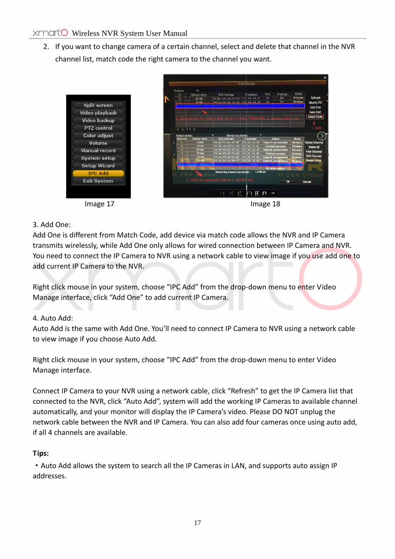
2. If you want to change camera of a certain channel, select and delete that channel in the NVR
channel list, match code the right camera to the channel you want.
Image 17 Image 18
3. Add One:
Add One is different from Match Code, add device via match code allows the NVR and IP Camera
transmits wirelessly, while Add One only allows for wired connection between IP Camera and NVR.
You need to connect the IP Camera to NVR using a network cable to view image if you use add one to
add current IP Camera to the NVR.
Right click mouse in your system, choose “IPC Add” from the drop-down menu to enter Video
Manage interface, click “Add One” to add current IP Camera.
4. Auto Add:
Auto Add is the same with Add One. You’ll need to connect IP Camera to NVR using a network cable
to view image if you choose Auto Add.
Right click mouse in your system, choose “IPC Add” from the drop-down menu to enter Video
Manage interface.
Connect IP Camera to your NVR using a network cable, click “Refresh” to get the IP Camera list that
connected to the NVR, click “Auto Add”, system will add the working IP Cameras to available channel
automatically, and your monitor will display the IP Camera’s video. Please DO NOT unplug the
network cable between the NVR and IP Camera. You can also add four cameras once using auto add,
if all 4 channels are available.
Tips:
·Auto Add allows the system to search all the IP Cameras in LAN, and supports auto assign IP
addresses.
Wireless NVR System User Manual
18
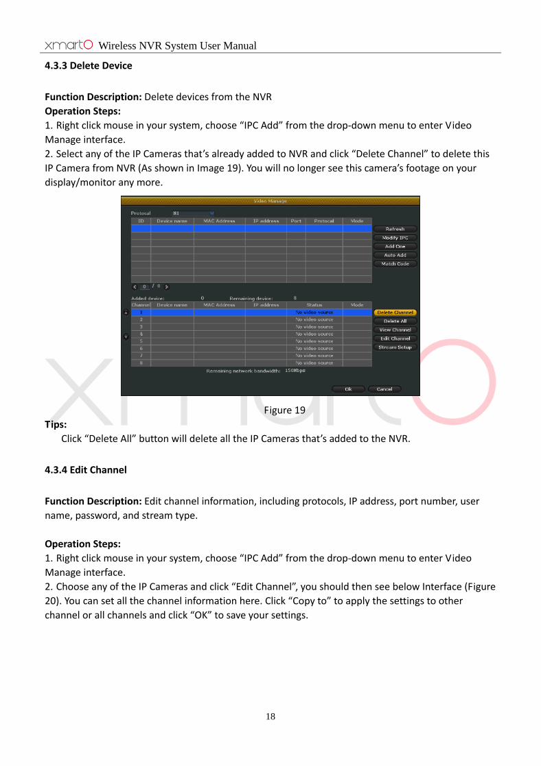
4.3.3 Delete Device
Function Description: Delete devices from the NVR
Operation Steps:
1. Right click mouse in your system, choose “IPC Add” from the drop-down menu to enter Video
Manage interface.
2. Select any of the IP Cameras that’s already added to NVR and click “Delete Channel” to delete this
IP Camera from NVR (As shown in Image 19). You will no longer see this camera’s footage on your
display/monitor any more.
Figure 19
Tips:
Click “Delete All” button will delete all the IP Cameras that’s added to the NVR.
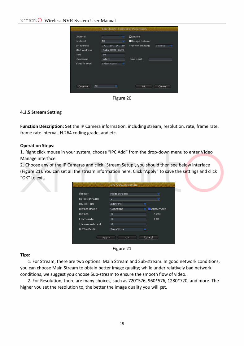
4.3.4 Edit Channel
Function Description: Edit channel information, including protocols, IP address, port number, user
name, password, and stream type.
Operation Steps:
1. Right click mouse in your system, choose “IPC Add” from the drop-down menu to enter Video
Manage interface.
2. Choose any of the IP Cameras and click “Edit Channel”, you should then see below Interface (Figure
20). You can set all the channel information here. Click “Copy to” to apply the settings to other
channel or all channels and click “OK” to save your settings.
Wireless NVR System User Manual
19
Figure 20
4.3.5 Stream Setting
Function Description: Set the IP Camera information, including stream, resolution, rate, frame rate,
frame rate interval, H.264 coding grade, and etc.
Operation Steps:
1. Right click mouse in your system, choose “IPC Add” from the drop-down menu to enter Video
Manage interface.
2. Choose any of the IP Cameras and click “Stream Setup”, you should then see below interface
(Figure 21). You can set all the stream information here. Click “Apply” to save the settings and click
“OK” to exit.
Figure 21
Tips:
1. For Stream, there are two options: Main Stream and Sub-stream. In good network conditions,
you can choose Main Stream to obtain better image quality; while under relatively bad network
conditions, we suggest you choose Sub-stream to ensure the smooth flow of video.
2. For Resolution, there are many choices, such as 720*576, 960*576, 1280*720, and more. The
higher you set the resolution to, the better the image quality you will get.

Wireless NVR System User Manual
20
4.4 Network Setting
4.4.1 Network Setup
Declaration: If the system is used for remote surveillance, you must set up the network to ensure it
work properly.
Default IP address: 192.168.1.114
Operation Steps:
1. Right click mouse in your system, choose “System setup” from the drop-down menu, click
“Network setup”, you’ll see below interface, as shown in Image 22.
Image 22
2. Configure Network Parameter: Go to “Network setup” to modify your device’s IP address, subnet
mask, gateway and etc., you can also check “DHCP” to automatically obtain IP address. Check “Device
ID” to show the device ID, which is used for remote access.
3. Click “Apply” to save the settings, or click “OK” to save and exit.
Detailed Feature List:
Name Function Description Note
IP Address Set the IP address of this device, you can choose to
manually input the IP address
Unselect the DHCP to manually set
your IP address
Subnet Mask Set the Subnet Mask
Gateway Set the Gateway
MAC Address Set the MAC Address Avoid using same MAC Address in
LAN
Web Port Transmit video signal and other control signals,
default is 80
Port 80 is used for web, PC client
and Mobile
DHCP Select DHCP to automatically obtain the IP address When DHCP is selected, you
cannot manually set the IP Address
Wireless NVR System User Manual
21
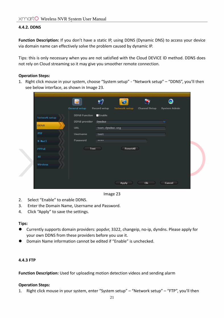
4.4.2. DDNS
Function Description: If you don’t have a static IP, using DDNS (Dynamic DNS) to access your device
via domain name can effectively solve the problem caused by dynamic IP.
Tips: this is only necessary when you are not satisfied with the Cloud DEVICE ID method. DDNS does
not rely on Cloud streaming so it may give you smoother remote connection.
Operation Steps:
1. Right click mouse in your system, choose “System setup” - “Network setup” – “DDNS”, you’ll then
see below interface, as shown in Image 23.
Image 23
2. Select “Enable” to enable DDNS.
3. Enter the Domain Name, Username and Password.
4. Click “Apply” to save the settings.
Tips:
Currently supports domain providers: popdvr, 3322, changeip, no-ip, dyndns. Please apply for
your own DDNS from these providers before you use it.
Domain Name information cannot be edited if “Enable” is unchecked.
4.4.3 FTP
Function Description: Used for uploading motion detection videos and sending alarm
Operation Steps:
1. Right click mouse in your system, enter “System setup” – “Network setup” – “FTP”, you’ll then
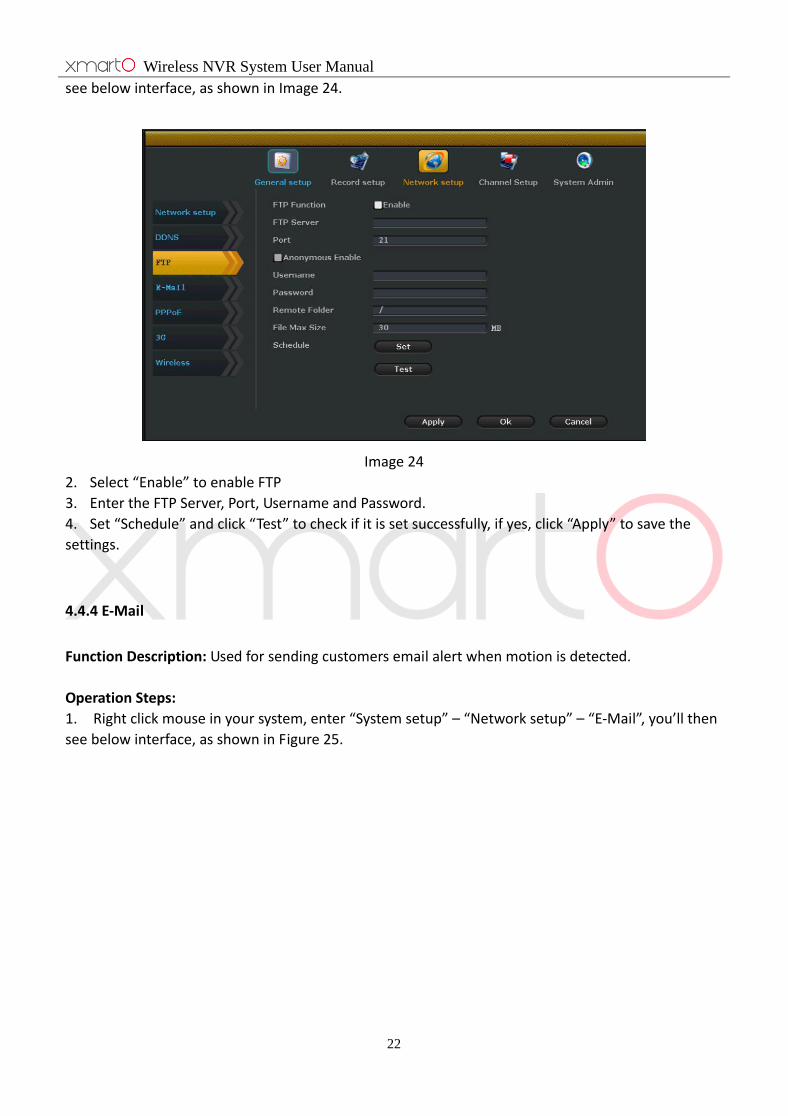
Wireless NVR System User Manual
22
see below interface, as shown in Image 24.
Image 24
2. Select “Enable” to enable FTP
3. Enter the FTP Server, Port, Username and Password.
4. Set “Schedule” and click “Test” to check if it is set successfully, if yes, click “Apply” to save the
settings.
4.4.4 E-Mail
Function Description: Used for sending customers email alert when motion is detected.
Operation Steps:
1. Right click mouse in your system, enter “System setup” – “Network setup” – “E-Mail”, you’ll then
see below interface, as shown in Figure 25.
Wireless NVR System User Manual
23
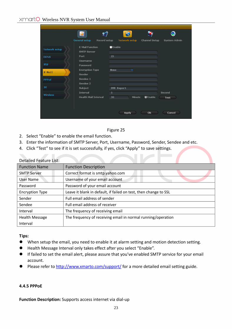
Figure 25
2. Select “Enable” to enable the email function.
3. Enter the information of SMTP Server, Port, Username, Password, Sender, Sendee and etc.
4. Click “Test” to see if it is set successfully, if yes, click “Apply” to save settings.
Detailed Feature List:
Function Name Function Description
SMTP Server Correct format is smtp.yahoo.com
User Name Username of your email account
Password Password of your email account
Encryption Type Leave it blank in default, if failed on test, then change to SSL
Sender Full email address of sender
Sendee Full email address of receiver
Interval The frequency of receiving email
Health Message
Interval
The frequency of receiving email in normal running/operation
Tips:
When setup the email, you need to enable it at alarm setting and motion detection setting.
Health Message Interval only takes effect after you select “Enable”.
If failed to set the email alert, please assure that you’ve enabled SMTP service for your email
account.
Please refer to http://www.xmarto.com/support/ for a more detailed email setting guide.
4.4.5 PPPoE
Function Description: Supports access internet via dial-up

Wireless NVR System User Manual
24
Operation Steps:
1. Right click mouse in your system, enter “System setup” – “Network setup” – “PPPoE”, you’ll then
see below interface, as shown in Image 26.
Figure 26
2. Select “Enable”, enter the Username and Password provided by ISP.
Tips:
PPPoE Function: for enable PPPoE, allowing access internet via dail-up; for disable
PPPoE
4.4.6 3G
Function description: this is to enable users who don’t have Internet service to use USB data stick to
connect the NVR to Internet.
Operation Steps:
1. Right click mouse in your system, enter “System setup” – “Network setup” – “3G”, you’ll then see
below interface, as shown in Image 27.

Wireless NVR System User Manual
25
Image 27
1. Select “Enable” to enable 3G Module.
2. Enter the information of Dial-Number, APN, PIN, Username, Password, and etc.
3. Click “Apply” to save settings.
4.4.7 Wireless
Function description: This enables users to change settings of the NVR’s Wi-Fi hotspot and password;
and some other router related settings.
ESSID: the default Wi-Fi hotspot name of the NVR
Password: the default password of the Wi-Fi hotspot; generated automatically by the system.
Note: changing the hotspot name or the password will cause losing connection with cameras; please
restore to factory settings if you lose camera connections; or follow 4.3.2 to add cameras to the NVR.

Wireless NVR System User Manual
26
4.5 PTZ Control (xmartO WOS series do not support PTZ now)
4.5.1 PTZ Parameter Setting
Prerequisites:
Before trying to control the speed dome or PTZ, you need to make sure that the decoder of this PTZ
has already connected to NVR, and also you need to set the parameters for the PTZ in NVR.
Operation Steps:
1. Right click mouse in your system, enter “System setup” – “Channel Setup” – “PTZ”, you’ll then
see below interface, as shown in Figure 28.
Image 28
Operation Guide as below:
Operation Target Function Description
Channel Choose the channel you want to set PTZ
Protocol Choose the correct protocol of this PTZ
Device Address Enter the specified decoder address
Baud Rate Choose the right baud rate to match with this PTZ’s baud rate
Copy to Choose the channel you want to copy the settings and click “Copy to” to apply
current channel’s settings to other channels
4.5.2 PTZ Control Operations
Operation Steps:
1. Double click the channel you want to set in main preview screen.
2. Right click mouse in that channel’s preview interface and choose the PTZ control, you’ll then see
below image, as shown in Figure 29.

Wireless NVR System User Manual
27
Image 29
Operation Explanation:
: Control the PTZ to rotate upward
: Control the PTZ to rotate downward
: Control the PTZ to rotate leftward
: Control the PTZ to rotate rightward
: Control the PTZ to rotate 360 degrees automatically
+: Adjust Zoom+, Focus+, Iris+.
-: Adjust Zoom-, Focus-, Iris-.
4.5.3 PTZ Auto Cruise Setup
Operation Steps:
1. Right click mouse in your system, choose “System setup” - “Channel Setup” - “PTZ Control”.
2. Click “?” at the right of “Preset” to enter the control interface to set presets.
3. Choose presets and set rotation direction.
4. Right click mouse to back to the setup interface, set the “Keep time”.
5. Click “Add” to finish setting this preset.
6. Repeat above 2-5 steps to add other presets.
7. Setup complete, check “Tour Start” to modify the rotation speed accordingly, as shown in Image
30.
Image 30
Wireless NVR System User Manual
28
8. Right click mouse to back to setup interface, click “Apply” to save settings.
Tips:
Presets are the tour spots, the PTZ tour from small to large spots automatically.
Keep time is the time length that the PTZ will stay at a preset.
Speed is the rotation speed that the PTZ tour from one preset to another preset.
4.6 Recording
4.6.1 Manual Record
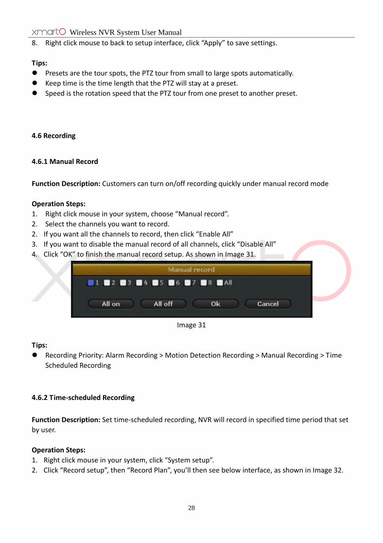
Function Description: Customers can turn on/off recording quickly under manual record mode
Operation Steps:
1. Right click mouse in your system, choose “Manual record”.
2. Select the channels you want to record.
2. If you want all the channels to record, then click “Enable All”
3. If you want to disable the manual record of all channels, click “Disable All”
4. Click “OK” to finish the manual record setup. As shown in Image 31.
Image 31
Tips:
Recording Priority: Alarm Recording > Motion Detection Recording > Manual Recording > Time
Scheduled Recording
4.6.2 Time-scheduled Recording
Function Description: Set time-scheduled recording, NVR will record in specified time period that set
by user.
Operation Steps:
1. Right click mouse in your system, click “System setup”.
2. Click “Record setup”, then “Record Plan”, you’ll then see below interface, as shown in Image 32.
Wireless NVR System User Manual
29
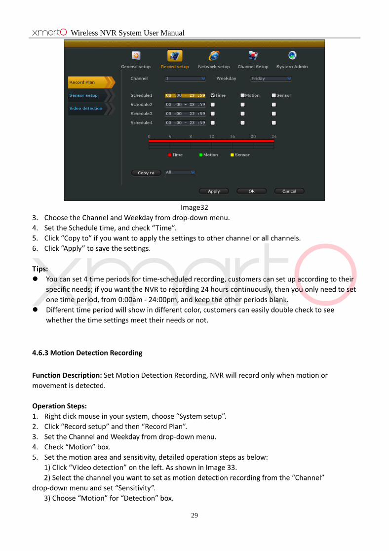
Image32
3. Choose the Channel and Weekday from drop-down menu.
4. Set the Schedule time, and check “Time”.
5. Click “Copy to” if you want to apply the settings to other channel or all channels.
6. Click “Apply” to save the settings.
Tips:
You can set 4 time periods for time-scheduled recording, customers can set up according to their
specific needs; if you want the NVR to recording 24 hours continuously, then you only need to set
one time period, from 0:00am - 24:00pm, and keep the other periods blank.
Different time period will show in different color, customers can easily double check to see
whether the time settings meet their needs or not.
4.6.3 Motion Detection Recording
Function Description: Set Motion Detection Recording, NVR will record only when motion or
movement is detected.
Operation Steps:
1. Right click mouse in your system, choose “System setup”.
2. Click “Record setup” and then “Record Plan”.
3. Set the Channel and Weekday from drop-down menu.
4. Check “Motion” box.
5. Set the motion area and sensitivity, detailed operation steps as below:
1) Click “Video detection” on the left. As shown in Image 33.
2) Select the channel you want to set as motion detection recording from the “Channel”
drop-down menu and set “Sensitivity”.
3) Choose “Motion” for “Detection” box.
Wireless NVR System User Manual
30
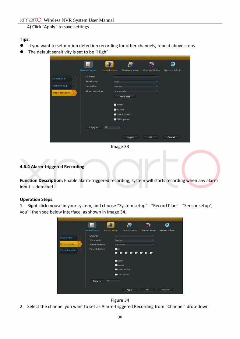
4) Click “Apply” to save settings.
Tips:
If you want to set motion detection recording for other channels, repeat above steps
The default sensitivity is set to be “High”
Image 33
4.6.4 Alarm-triggered Recording
Function Description: Enable alarm-triggered recording, system will starts recording when any alarm
input is detected.
Operation Steps:
1. Right click mouse in your system, and choose “System setup” - “Record Plan” - “Sensor setup”,
you’ll then see below interface, as shown in Image 34.
Figure 34
2. Select the channel you want to set as Alarm-triggered Recording from “Channel” drop-down

Wireless NVR System User Manual
31
menu, set work Mode is “Enable”.
3. Select the “Record channel”.
4. Please refer to “4.6.2 Time-scheduled Recording Setup” to set the Alarm-triggered Recording;
make sure to check the “Alarm” box.
5. Click “OK” to save the settings.
Tips:
Repeat above steps to set other channels to be Alarm-triggered Recording.
If other channels’ Alarm-triggered Recording settings are the same to this channel, click “Copy
to” to apply current channel’s settings to other channel or all channels.
4.7 Video Playback
4.7.1 Quick Playback
Function Description: Enable fast playback, customers can quickly retrieval recent video data.
Operation Steps:
1. Right click mouse in your system and choose “Video playback”
2. Select the playback time from drop-down menu, uses can select 5 minutes, 10 minutes, 30
minutes based on their needs. User can choose any channel to playback. As shown in Image 35.
Image 35
Tips:
Before you playback, please make sure that you’ve installed a hard drive in the NVR, and you’ve
enabled the recording.
4.7.2 Regular Playback
Function Description: Enable normal playback, customers can search for videos based on recording
type and time.
Wireless NVR System User Manual
32
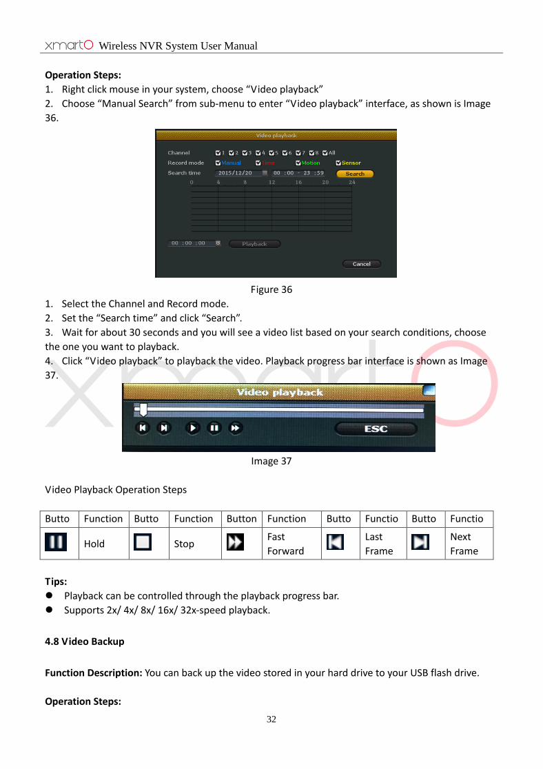
Operation Steps:
1. Right click mouse in your system, choose “Video playback”
2. Choose “Manual Search” from sub-menu to enter “Video playback” interface, as shown is Image
36.
Figure 36
1. Select the Channel and Record mode.
2. Set the “Search time” and click “Search”.
3. Wait for about 30 seconds and you will see a video list based on your search conditions, choose
the one you want to playback.
4. Click “Video playback” to playback the video. Playback progress bar interface is shown as Image
37.
Image 37
Video Playback Operation Steps
Butto
n
Function Butto
n
Function Button Function Butto
n
Functio
n
Butto
n
Functio
n
Hold Stop Fast
Forward Last
Frame Next
Frame
Tips:
Playback can be controlled through the playback progress bar.
Supports 2x/ 4x/ 8x/ 16x/ 32x-speed playback.
4.8 Video Backup
Function Description: You can back up the video stored in your hard drive to your USB flash drive.
Operation Steps:
Wireless NVR System User Manual
33
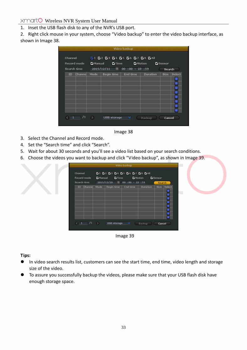
1. Inset the USB flash disk to any of the NVR’s USB port.
2. Right click mouse in your system, choose “Video backup” to enter the video backup interface, as
shown in Image 38.
Image 38
3. Select the Channel and Record mode.
4. Set the “Search time” and click “Search”.
5. Wait for about 30 seconds and you’ll see a video list based on your search conditions.
6. Choose the videos you want to backup and click “Video backup”, as shown in Image 39.
Image 39
Tips:
In video search results list, customers can see the start time, end time, video length and storage
size of the video.
To assure you successfully backup the videos, please make sure that your USB flash disk have
enough storage space.
Wireless NVR System User Manual
34
4.9 Alarm
4.9.1 Motion Detection Alarm
Function Description: When system detects motion detection in the selected area, it will trigger
alarm and output alarm.
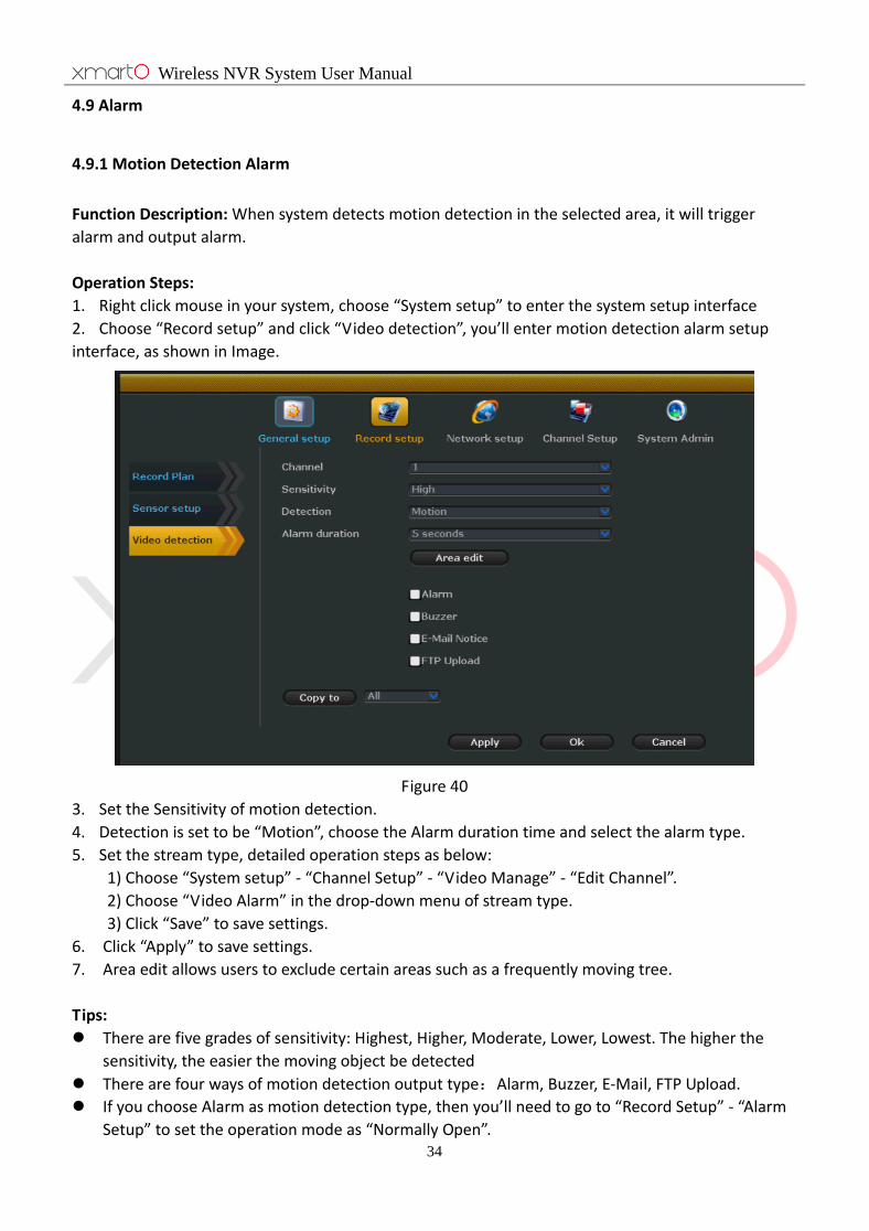
Operation Steps:
1. Right click mouse in your system, choose “System setup” to enter the system setup interface
2. Choose “Record setup” and click “Video detection”, you’ll enter motion detection alarm setup
interface, as shown in Image.
Figure 40
3. Set the Sensitivity of motion detection.
4. Detection is set to be “Motion”, choose the Alarm duration time and select the alarm type.
5. Set the stream type, detailed operation steps as below:
1) Choose “System setup” - “Channel Setup” - “Video Manage” - “Edit Channel”.
2) Choose “Video Alarm” in the drop-down menu of stream type.
3) Click “Save” to save settings.
6. Click “Apply” to save settings.
7. Area edit allows users to exclude certain areas such as a frequently moving tree.
Tips:
There are five grades of sensitivity: Highest, Higher, Moderate, Lower, Lowest. The higher the
sensitivity, the easier the moving object be detected
There are four ways of motion detection output type:Alarm, Buzzer, E-Mail, FTP Upload.
If you choose Alarm as motion detection type, then you’ll need to go to “Record Setup” - “Alarm
Setup” to set the operation mode as “Normally Open”.

Wireless NVR System User Manual
35
If you set certain areas to be excluded from the detect areas and you still get alarm (such as
buzzer), it could be triggered by other channels.(channel 2, channel 3, channel 4…)
4.9.2 Video Loss Alarm
Function Description: If any channel lost video, users get alarms. (ex.buzzer)
Operation Steps:
1. Right click mouse in your system, choose “System setup” to enter system setup interface.
2. Choose “Record setup” - “Video detection”.
3. Choose “Video Loss” from the Detection drop-down box, as shown in Image 41.
Image 41
4. Set the Alarm duration time and select motion detection output type.
5. Click “Apply” to save settings.
Tips:
Click “Copy to” to copy settings for current channel to other channel or all channels.
4.10 General setup
4.10.1 General setup
Function Description: Basic settings and parameters.
Operation Steps:
1. Right click the mouse in your system; choose “System setup” to enter the system setup interface.
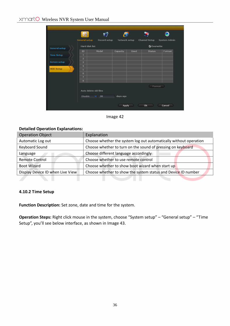
2. Choose “General setup” - “General setup”, as shown in Image 42.
Wireless NVR System User Manual
36
Image 42
Detailed Operation Explanations:
Operation Object Explanation
Automatic Log out Choose whether the system log out automatically without operation
Keyboard Sound Choose whether to turn on the sound of pressing on keyboard
Language Choose different language accordingly
Remote Control Choose whether to use remote control
Boot Wizard Choose whether to show boot wizard when start up
Display Device ID when Live View Choose whether to show the system status and Device ID number
4.10.2 Time Setup
Function Description: Set zone, date and time for the system.
Operation Steps: Right click mouse in the system, choose “System setup” – “General setup” – “Time
Setup”, you’ll see below interface, as shown in Image 43.
Wireless NVR System User Manual
37
Image 43
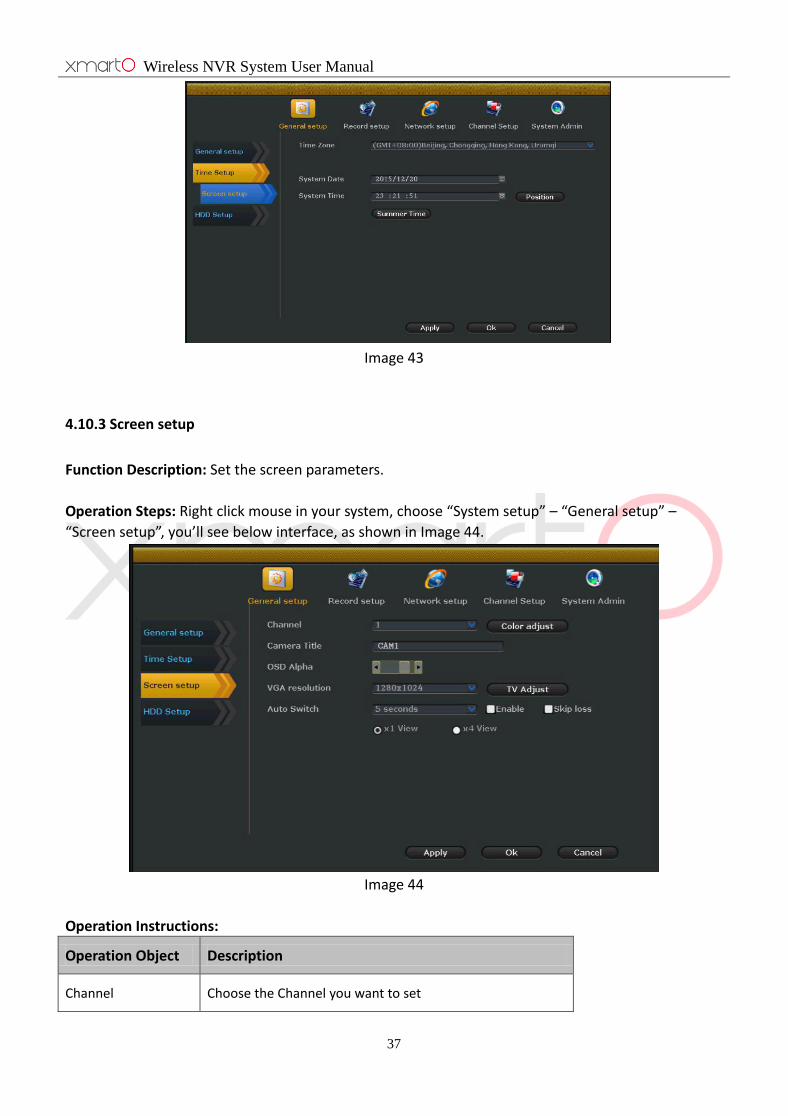
4.10.3 Screen setup
Function Description: Set the screen parameters.
Operation Steps: Right click mouse in your system, choose “System setup” – “General setup” –
“Screen setup”, you’ll see below interface, as shown in Image 44.
Image 44
Operation Instructions:
Operation Object Description
Channel Choose the Channel you want to set

Wireless NVR System User Manual
38
Camera Title Modify the Camera Title
Color adjust Set the color tone, brightness, saturation, and contrast
OSD Alpha Modify the OSD Alpha
VGA resolution Select the correct screen resolution
Auto Switch Whether to enable auto switch and set the switch time
Tips:
Skip video loss means if the screen does not show image of any channel, this channel will not be
displayed at auto switch
Choose 1 or 4 to set how many channels be displayed at a time at auto switch, 1 means display
only one channel at a time, while 4 means display 4 channels at a time
VGA resolution should match your screen resolution. If your NVR outputs different resolution
that your screen takes, you may not get display on the screen. Please connect the NVR to a high
resolution screen and set it to correct resolution and then connect back to your primary screen.
4.10.4 Hard drive Settings
Function Description: Allows you to format your hard drive.
Operation Steps:
1. Right click mouse in your system, choose “System setup” to enter system setup interface.
2. Choose “General setup” – “HDD Setup”, you’ll see below interface, as shown in Image 45.
Image 45
3. Check installed hard drive information here, including Model, Capacity, Used, Status, and Format.
4. Check “Overwrite” to enable auto overwrite.

Wireless NVR System User Manual
39
5. Click the hard drive to format it if needed.
6. Select “Customize” in drop-down menu and set the days (auto delete files of how many days
before) if you want to auto delete old files.
7. Click “Apply” to save the settings.
Tips:
Enable auto overwrite means hard drive will automatically overwrite earliest video files when it is
full.
When click “Formatting”, system will pop up a dialog box, reading “All data files will be deleted
after formatting, click OK to confirm”, click “OK” to start formatting.
Auto delete old files: Select “Customize” and set the days (auto delete files of how many days
before) with a digital keyboard, you can set up to 255 days. Select “OFF” to disable this function.
4.11 Device maintenance and management
4.11.1 System information
System version
Function Description: User can check device’s information, including Device name, Device model,
Device SN, H/W version, S/W version, and Built time.
Operation Steps:
Right click mouse in your system, choose “System setup” – “System Admin” – “System version”, you’ll
the see below interface, as shown in Figure 46.
Figure 46
Tips:
System version is very important for our future maintenance; customers might be required to
provide the device’s version information when maintenance is needed.
Wireless NVR System User Manual
40
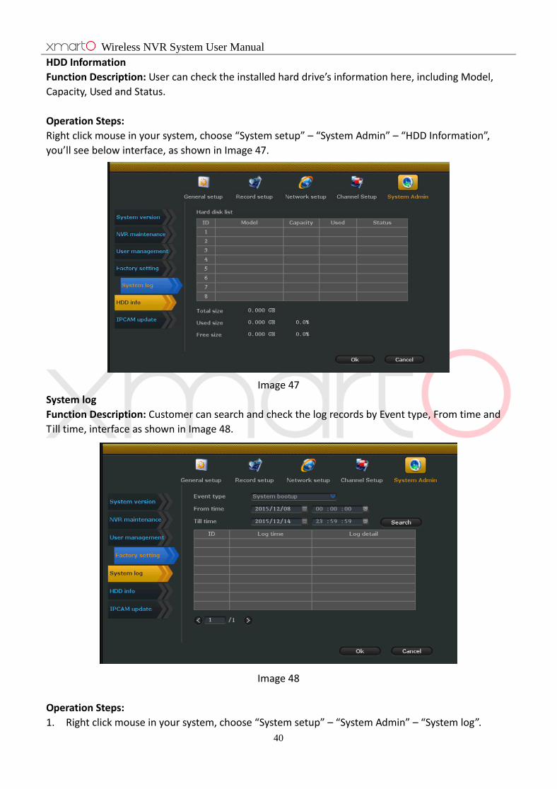
HDD Information
Function Description: User can check the installed hard drive’s information here, including Model,
Capacity, Used and Status.
Operation Steps:
Right click mouse in your system, choose “System setup” – “System Admin” – “HDD Information”,
you’ll see below interface, as shown in Image 47.
Image 47
System log
Function Description: Customer can search and check the log records by Event type, From time and
Till time, interface as shown in Image 48.
Image 48
Operation Steps:
1. Right click mouse in your system, choose “System setup” – “System Admin” – “System log”.
Wireless NVR System User Manual
41
2. Select the Event type from drop-down box.
3. Set the From time and Till time, click “Search”, you’ll see the log information displayed there.
Tips:
Click left and right arrow to read previous and next page’s log information
Log information are saved in the hard drive, formatting hard drive will delete all log information
Time type can be set as: system starting up, system shutdown, system configuration change,
record, alarm and more.
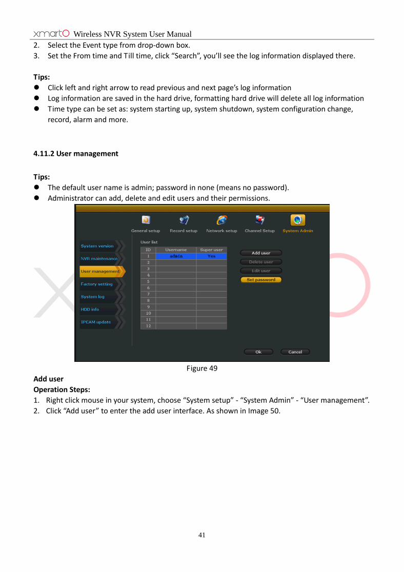
4.11.2 User management
Tips:
The default user name is admin; password in none (means no password).
Administrator can add, delete and edit users and their permissions.
Figure 49
Add user
Operation Steps:
1. Right click mouse in your system, choose “System setup” - “System Admin” - “User management”.
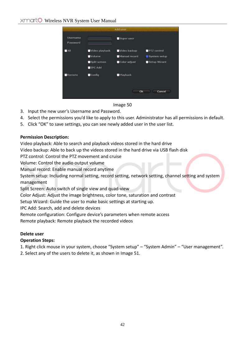
2. Click “Add user” to enter the add user interface. As shown in Image 50.
Wireless NVR System User Manual
42
Image 50
3. Input the new user’s Username and Password.
4. Select the permissions you’d like to apply to this user. Administrator has all permissions in default.
5. Click “OK” to save settings, you can see newly added user in the user list.
Permission Description:
Video playback: Able to search and playback videos stored in the hard drive
Video backup: Able to back up the videos stored in the hard drive via USB flash disk
PTZ control: Control the PTZ movement and cruise
Volume: Control the audio output volume
Manual record: Enable manual record anytime
System setup: Including normal setting, record setting, network setting, channel setting and system
management
Split Screen: Auto switch of single view and quad-view
Color Adjust: Adjust the image brightness, color tone, saturation and contrast
Setup Wizard: Guide the user to make basic settings at starting up.
IPC Add: Search, add and delete devices
Remote configuration: Configure device’s parameters when remote access
Remote playback: Remote playback the recorded videos
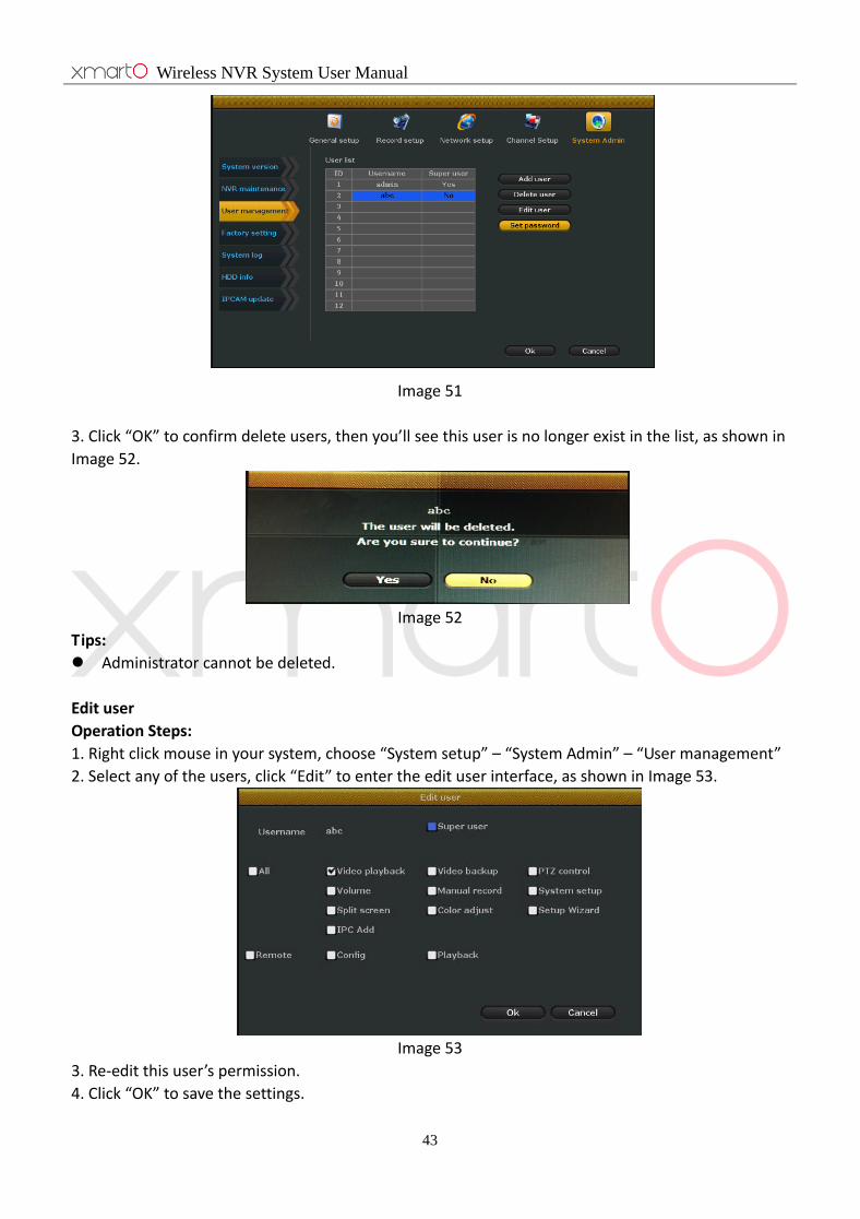
Delete user
Operation Steps:
1. Right click mouse in your system, choose “System setup” – “System Admin” – “User management”.
2. Select any of the users to delete it, as shown in Image 51.
Wireless NVR System User Manual
43
Image 51
3. Click “OK” to confirm delete users, then you’ll see this user is no longer exist in the list, as shown in
Image 52.
Image 52
Tips:
Administrator cannot be deleted.
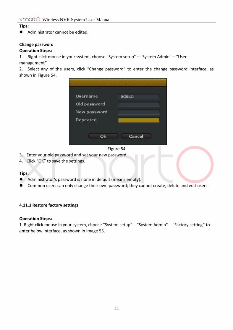
Edit user
Operation Steps:
1. Right click mouse in your system, choose “System setup” – “System Admin” – “User management”
2. Select any of the users, click “Edit” to enter the edit user interface, as shown in Image 53.
Image 53
3. Re-edit this user’s permission.
4. Click “OK” to save the settings.
Wireless NVR System User Manual
44
Tips:
Administrator cannot be edited.
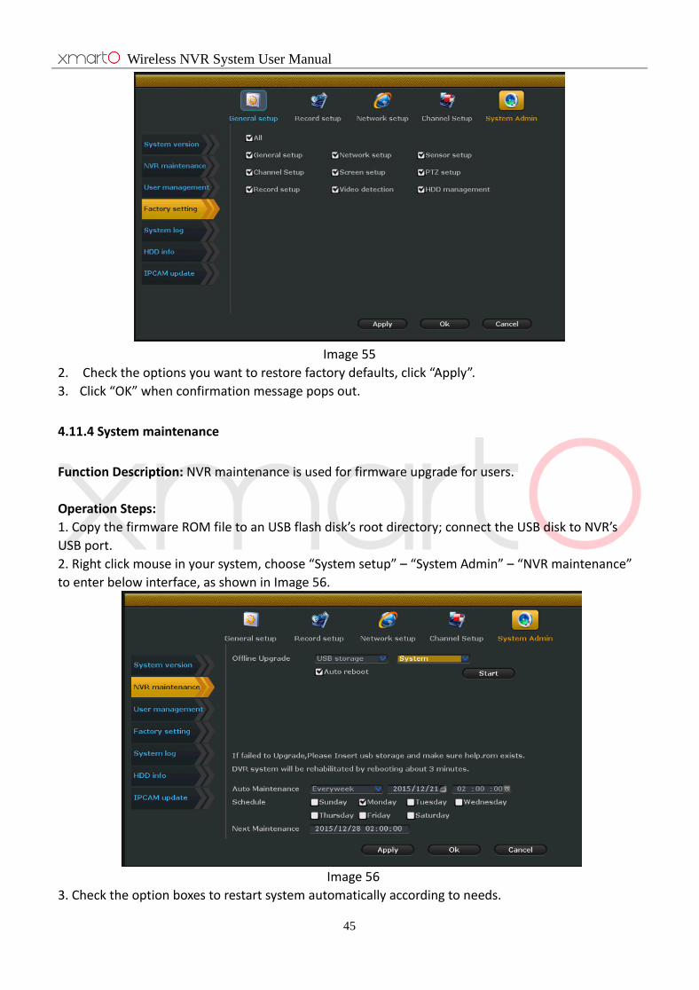
Change password
Operation Steps:
1. Right click mouse in your system, choose “System setup” – “System Admin” – “User
management”.
2. Select any of the users, click “Change password” to enter the change password interface, as
shown in Figure 54.
Figure 54
3. Enter your old password and set your new password.
4. Click “OK” to save the settings.
Tips:
Administrator’s password is none in default (means empty).
Common users can only change their own password; they cannot create, delete and edit users.
4.11.3 Restore factory settings
Operation Steps:
1. Right click mouse in your system, choose “System setup” – “System Admin” – “Factory setting” to
enter below interface, as shown in Image 55.
Wireless NVR System User Manual
45
Image 55
2. Check the options you want to restore factory defaults, click “Apply”.
3. Click “OK” when confirmation message pops out.
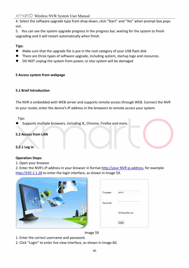
4.11.4 System maintenance
Function Description: NVR maintenance is used for firmware upgrade for users.
Operation Steps:
1. Copy the firmware ROM file to an USB flash disk’s root directory; connect the USB disk to NVR’s
USB port.
2. Right click mouse in your system, choose “System setup” – “System Admin” – “NVR maintenance”
to enter below interface, as shown in Image 56.
Image 56
3. Check the option boxes to restart system automatically according to needs.
Wireless NVR System User Manual
46
4. Select the software upgrade type from drop-down, click “Start” and “Yes” when prompt box pops
out.
5. You can see the system upgrade progress in the progress bar, waiting for the system to finish
upgrading and it will restart automatically when finish.
Tips:
Make sure that the upgrade file is put in the root category of your USB flash disk
There are three types of software upgrade, including system, startup logo and resources.
DO NOT unplug the system from power, or else system will be damaged
5 Access system from webpage
5.1 Brief Introduction
The NVR is embedded with WEB server and supports remote access through WEB. Connect the NVR
to your router, enter the device’s IP address in the browsers to remote access your system.
Tips:
Supports multiple browsers, including IE, Chrome, Firefox and more.
5.2 Access from LAN
5.2.1 Log in
Operation Steps:
1. Open your browser
2. Enter the NVR’s IP address in your browser in format http://your NVR ip address, for example:
http://192.1.1.28 to enter the login interface, as shown in Image 59.
Image 59
1. Enter the correct username and password.
2. Click “Login” to enter live view interface, as shown in Image 60.

Wireless NVR System User Manual
47
Image 60
6. If for first time use, please download and run the WebClient.exe control according to the prompt
message, as shown in Image 61.
Image 61
7. Login again to live view your system, as shown in Image 62.
Image 62
Tips:
Wireless NVR System User Manual
48
IP address can be found in “System Setup” – “Network Setup”
Supports multiple users to view simultaneously from different PC
If the WEB port has been changed (default port is 80), then you’ll need to add port number when
input IP address in the browser, for example: http://192.168.1.28:102 (port is 102)
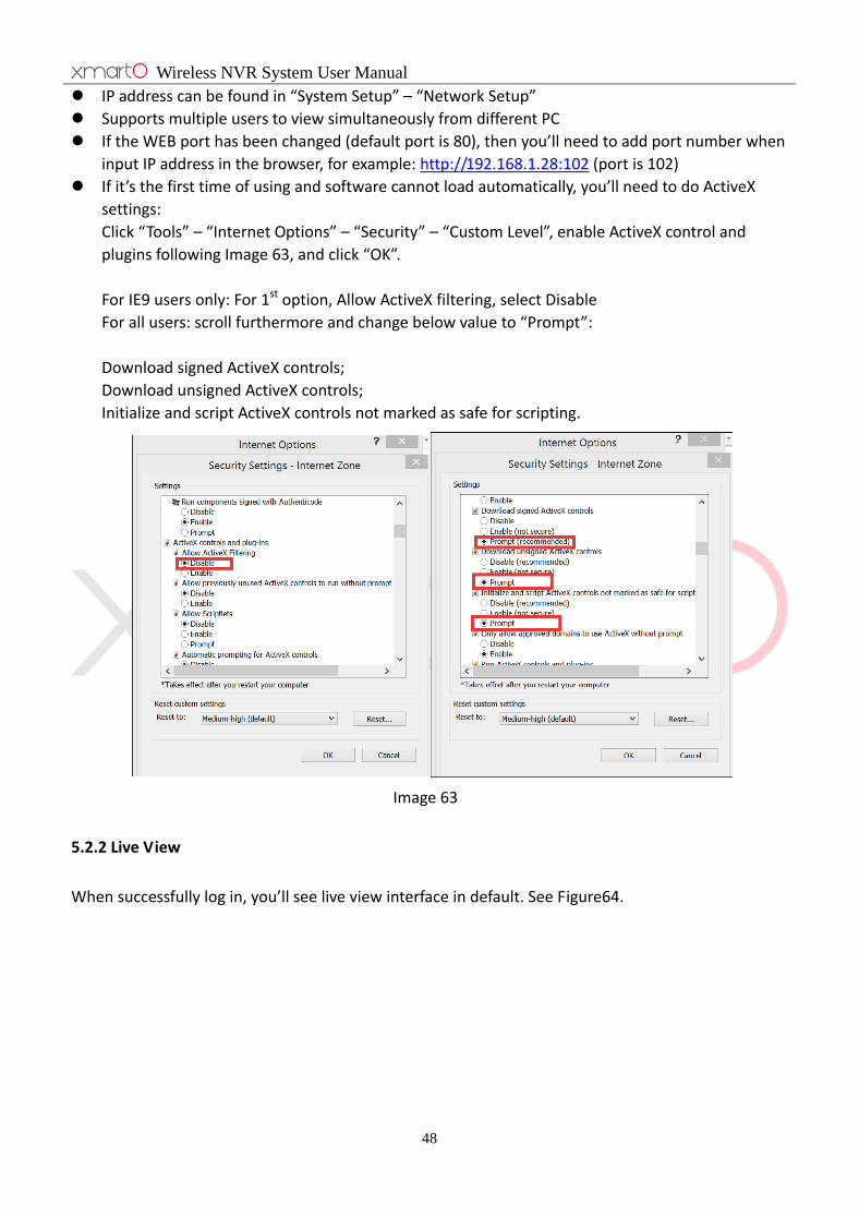
If it’s the first time of using and software cannot load automatically, you’ll need to do ActiveX
settings:
Click “Tools” – “Internet Options” – “Security” – “Custom Level”, enable ActiveX control and
plugins following Image 63, and click “OK”.
For IE9 users only: For 1st option, Allow ActiveX filtering, select Disable
For all users: scroll furthermore and change below value to “Prompt”:
Download signed ActiveX controls;
Download unsigned ActiveX controls;
Initialize and script ActiveX controls not marked as safe for scripting.
Image 63
5.2.2 Live View
When successfully log in, you’ll see live view interface in default. See Figure64.

Wireless NVR System User Manual
49
Image 64
Tips:
Supports 1, 4, 9, 16, 25, 36 split screen, means you can view 1, 4, 9, 16, 25, 36 channels
simultaneously
Supports Main Stream and Sub Stream two options
5.2.3 Playback
Operation Steps:
1. Click “Playback” button in live view interface.
2. Enter playback interface, as shown below:
2. Set the search time, type and channel, click “Search”
3. Choose the playback channel to playback recorded videos.
Tips:
Common user needs permission to remote playback. Go to “System Setup” – “System
Management” – “User Management” – “Edit User” to check and set the remote playback
Channel List
PTZ
Control
Configure Turn ON/OFF Volume
Wireless NVR System User Manual
50
permission for this user.
5.2.4 Configure
Operation Steps:
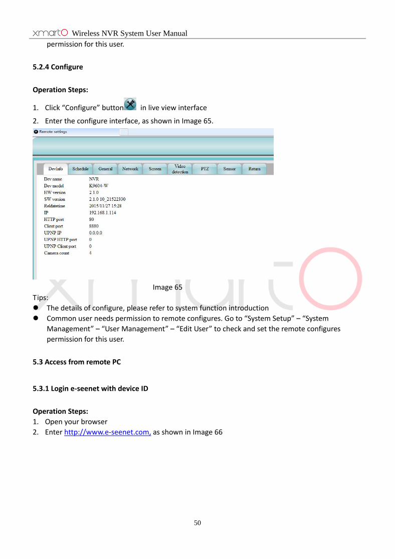
1. Click “Configure” button in live view interface
2. Enter the configure interface, as shown in Image 65.
Image 65
Tips:
The details of configure, please refer to system function introduction
Common user needs permission to remote configures. Go to “System Setup” – “System
Management” – “User Management” – “Edit User” to check and set the remote configures
permission for this user.
5.3 Access from remote PC
5.3.1 Login e-seenet with device ID
Operation Steps:
1. Open your browser
2. Enter http://www.e-seenet.com, as shown in Image 66

Wireless NVR System User Manual
51
Image 66
3. Enter the correct device ID, user name and password.
4. Click login to enter live view interface, as shown in Image 67.
Image 67
Tips:
Get the device ID by go to “System Setup” - “Network Setting” and check Eseenet(P2P), device
will then be displayed
To successfully remote access your system, the device ID should be ONLINE.
If this Cloud P2P connection is not smooth in your network, please refer to 4.4.2 to use DDNS
method to get smoother connection.

Wireless NVR System User Manual
52
5.3.2 Log in with User ID
Function Description: Log in with user name can solve the limitation of managing only one device by
log in with device ID
Operation Steps:
1. Open your browser.
2. Enter http://www.e-seenet.com, choose “Log in with Username”, as shown in Image 68.
Image 68
3. User can follow the prompt message to create an account when first login
Tips:
Supports Chinese and English two languages
6. Access from smartphone
Operation Steps:
1. Software download
Search and download App “ESEENET+” from Apple App Store or Google Play.

Wireless NVR System User Manual
53
2. Add Device
1) Open your mobile app and click “+” to add device
2) Input the system’s connection information, as shown in Image 69
Image 69
3) OK and go back to device list, click the device name to view live video, as shown in Image 70.

Wireless NVR System User Manual
54
Image 70
Stop
Capture snapshot
Record Video to mobile
Settings
3. Remote Playback
Wireless NVR System User Manual
55
Image 71
7. Appendix
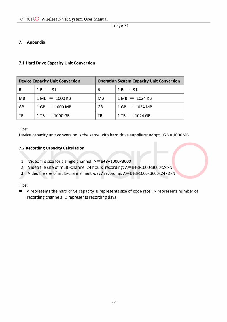
7.1 Hard Drive Capacity Unit Conversion
Device Capacity Unit Conversion Operation System Capacity Unit Conversion
B 1 B = 8 b B 1 B = 8 b
MB 1 MB = 1000 KB MB 1 MB = 1024 KB
GB 1 GB = 1000 MB GB 1 GB = 1024 MB
TB 1 TB = 1000 GB TB 1 TB = 1024 GB
Tips:
Device capacity unit conversion is the same with hard drive suppliers; adopt 1GB = 1000MB
7.2 Recording Capacity Calculation
1. Video file size for a single channel: A=B÷8÷1000×3600
2. Video file size of multi-channel 24 hours’ recording: A=B÷8÷1000×3600×24×N
3. Video file size of multi-channel multi-days’ recording: A=B÷8÷1000×3600×24×D×N
Tips:
A represents the hard drive capacity, B represents size of code rate , N represents number of
recording channels, D represents recording days