Embed Size (px)
Citation preview
- 1 -
CRN/D 10771 CE
01 / 00
User Manual
TWK-ELEKTRONIK GmbH · D-40041 Düsseldorf · PB 10 50 63 · T. 02 11/63 20 67 · F. 02 11/63 77 05 · e-mail: [email protected] · http://www.twk.de
CRN/D encoderas a subscriber in DeviceNet
Accompanying data sheet: CRN/D 10770

- 2 -
COPYRIGHT: The Operating Instructions TZY 10771
is owned by TWK-ELEKTRONIK GmbH and is
protected by copyright laws and international treaty provisions.
© 1999 by TWK-ELEKTRONIK GmbH
POB 10 50 63 n 40041 Düsseldorf n Germany
Tel. +49/211/63 20 67 n Fax +49/211/63 77 05
e-mail: [email protected] n internet: www.twk.de
- 3 -
Table of contents
1. Introduction ................................................................................................................ 5
2. Schematic circuit diagram: TWK encoder for DeviceNet ....................................... 6
3. Installation instructions ............................................................................................. 63.1 Encoder in plug-in version ................................................................................................................ 6
3.2 Encoder with connecting cap ........................................................................................................... 7
3.2.1 Setting the subscriber address (MAC ID) ...................................................................................... 7
3.2.2 Setting the baudrate ...................................................................................................................... 7
3.2.3 Status LED ................................................................................................................................... 8
4. The encoder operating modes .................................................................................. 94.1 Polling mode .................................................................................................................................... 9
4.2 Bit strobed mode .............................................................................................................................. 9
4.3 Change-of-state mode ...................................................................................................................... 9
4.4 Cyclical mode .................................................................................................................................. 9
5. Encoder parameters ................................................................................................ 105.1 Parameter description .................................................................................................................... 10
5.2 Encoder parameter values ............................................................................................................. 11
6. Encoder input data .................................................................................................. 11
7. Encoder status information .................................................................................... 12
8. The DeviceNet layer 7 protocol ............................................................................... 138.1 DeviceNet object structure ............................................................................................................. 13
8.2 The encoder objects ....................................................................................................................... 13
8.2.1 Identity Object ............................................................................................................................ 15
8.2.2 Message Router Object ............................................................................................................... 15
8.2.3 DeviceNet Object ........................................................................................................................ 16
8.2.4 Assembly Object ........................................................................................................................ 16
8.2.5 Connection Object ....................................................................................................................... 17
8.2.6 Position Sensor Objekt ................................................................................................................ 18
8.3 DeviceNet connections .................................................................................................................. 19
8.4 The DeviceNet protocol .................................................................................................................. 20
8.5 Establishment of a connection to the encoder ................................................................................ 20
8.6 Encoder parameterisation ............................................................................................................... 21
8.7 Request encoder input data ............................................................................................................ 22
8.8 Request status information ............................................................................................................ 22
8.9 Back parameter values up in EEPROM ......................................................................................... 23
8.10 Set parameter values to default status ......................................................................................... 23
9. DeviceNet Manager ................................................................................................. 249.1 Installation of EDS file ................................................................................................................... 24
9.2 Integration into the bus................................................................................................................... 25
9.3 Parameterise encoder .................................................................................................................... 26
9.4 Integrate encoder into the scan list ................................................................................................ 28
9.5 Go on-line and transfer data ........................................................................................................... 31
9.6 Set encoder address and baudrate in plug-in version...................................................................... 32
9.7 Store parameters in EEPROM ....................................................................................................... 34
0. Table of contents
- 4 -
9.8 Load parameter default values ....................................................................................................... 34
9.9 Read out arbitrary attribute ............................................................................................................. 35
10. RS-Networx for DeviceNet .................................................................................... 3610.1 Installation of EDS file ................................................................................................................. 36
10.2 Integration into the bus ................................................................................................................. 37
10.3 Parameterise encoder ................................................................................................................... 38
10.4 Integrate encoder into the scan list .............................................................................................. 39
10.5 Set encoder address and baudrate in plug-in version .................................................................... 41
10.6 Store parameters in EEPROM ..................................................................................................... 41
10.7 Load parameter default values ..................................................................................................... 42
10.8 Read out arbitrary attribute ........................................................................................................... 43
Appendix A: Literature ................................................................................................ 43
0. Table of contents
- 5 -
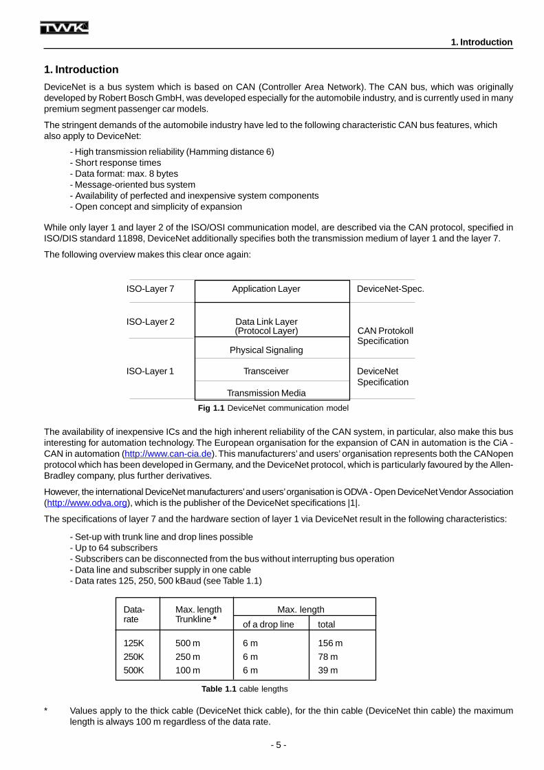
ISO-Layer 7 Application Layer DeviceNet-Spec.
ISO-Layer 2 Data Link Layer(Protocol Layer) CAN Protokoll
SpecificationPhysical Signaling
ISO-Layer 1 Transceiver DeviceNetSpecification
Transmission Media
Table 1.1 cable lengths
Fig 1.1 DeviceNet communication model
Data- Max. length Max. lengthrate Trunkline * of a drop line total
125K 500 m 6 m 156 m
250K 250 m 6 m 78 m
500K 100 m 6 m 39 m
1. Introduction
DeviceNet is a bus system which is based on CAN (Controller Area Network). The CAN bus, which was originallydeveloped by Robert Bosch GmbH, was developed especially for the automobile industry, and is currently used in manypremium segment passenger car models.
The stringent demands of the automobile industry have led to the following characteristic CAN bus features, whichalso apply to DeviceNet:
- High transmission reliability (Hamming distance 6)- Short response times- Data format: max. 8 bytes- Message-oriented bus system- Availability of perfected and inexpensive system components- Open concept and simplicity of expansion
While only layer 1 and layer 2 of the ISO/OSI communication model, are described via the CAN protocol, specified inISO/DIS standard 11898, DeviceNet additionally specifies both the transmission medium of layer 1 and the layer 7.
The following overview makes this clear once again:
The availability of inexpensive ICs and the high inherent reliability of the CAN system, in particular, also make this businteresting for automation technology. The European organisation for the expansion of CAN in automation is the CiA -CAN in automation (http://www.can-cia.de). This manufacturers’ and users’ organisation represents both the CANopenprotocol which has been developed in Germany, and the DeviceNet protocol, which is particularly favoured by the Allen-Bradley company, plus further derivatives.
However, the international DeviceNet manufacturers’ and users’ organisation is ODVA - Open DeviceNet Vendor Association(http://www.odva.org), which is the publisher of the DeviceNet specifications |1|.
The specifications of layer 7 and the hardware section of layer 1 via DeviceNet result in the following characteristics:
- Set-up with trunk line and drop lines possible- Up to 64 subscribers- Subscribers can be disconnected from the bus without interrupting bus operation- Data line and subscriber supply in one cable- Data rates 125, 250, 500 kBaud (see Table 1.1)
* Values apply to the thick cable (DeviceNet thick cable), for the thin cable (DeviceNet thin cable) the maximumlength is always 100 m regardless of the data rate.
1. Introduction
- 6 -
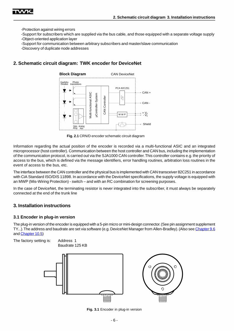
Fig. 2.1 CRN/D encoder schematic circuit diagram
2. Schematic circuit diagram: TWK encoder for DeviceNet
3. Installation instructions
Block Diagram
DiodesGaAlAs
µCon
trol
ler-
Sys
tem
CA
N C
ontr
olle
r
Mul
ti-fu
nctio
nal A
SIC
transistorsPhoto
PCA 82C251
CAN DeviceNet
M W P
CAN +
+ V- VS
S
AnalogArrayOpto
Asic
CAN -
Shield
Fig. 3.1 Encoder in plug-in version
-Protection against wiring errors-Support for subscribers which are supplied via the bus cable, and those equipped with a separate voltage supply-Object-oriented application layer-Support for communication between arbitrary subscribers and master/slave communication-Discovery of duplicate node addresses
Information regarding the actual position of the encoder is recorded via a multi-functional ASIC and an integratedmicroprocessor (host controller). Communication between the host controller and CAN bus, including the implementationof the communication protocol, is carried out via the SJA1000 CAN controller. This controller contains e.g. the priority ofaccess to the bus, which is defined via the message identifiers, error handling routines, arbitration loss routines in theevent of access to the bus, etc.
The interface between the CAN controller and the physical bus is implemented with CAN transceiver 82C251 in accordancewith CiA Standard ISO/DIS 11898. In accordance with the DeviceNet specifications, the supply voltage is equipped withan MWP (Mis-Wiring Protection) - switch – and with an RC combination for screening purposes.
In the case of DeviceNet, the terminating resistor is never integrated into the subscriber, it must always be separatelyconnected at the end of the trunk line
3.1 Encoder in plug-in version
The plug-in version of the encoder is equipped with a 5-pin micro or mini-design connector. (See pin assignment supplementTY...). The address and baudrate are set via software (e.g. DeviceNet Manager from Allen-Bradley). (Also see Chapter 9.6and Chapter 10.5)
The factory setting is: Address 1Baudrate 125 KB
2. Schematic circuit diagram 3. Installation instructions
- 7 -
3.2.2 Setting the baudrate
Table 3.2 Setting the baudrate
Table 3.1 Setting the subscriber address (MAC-ID)
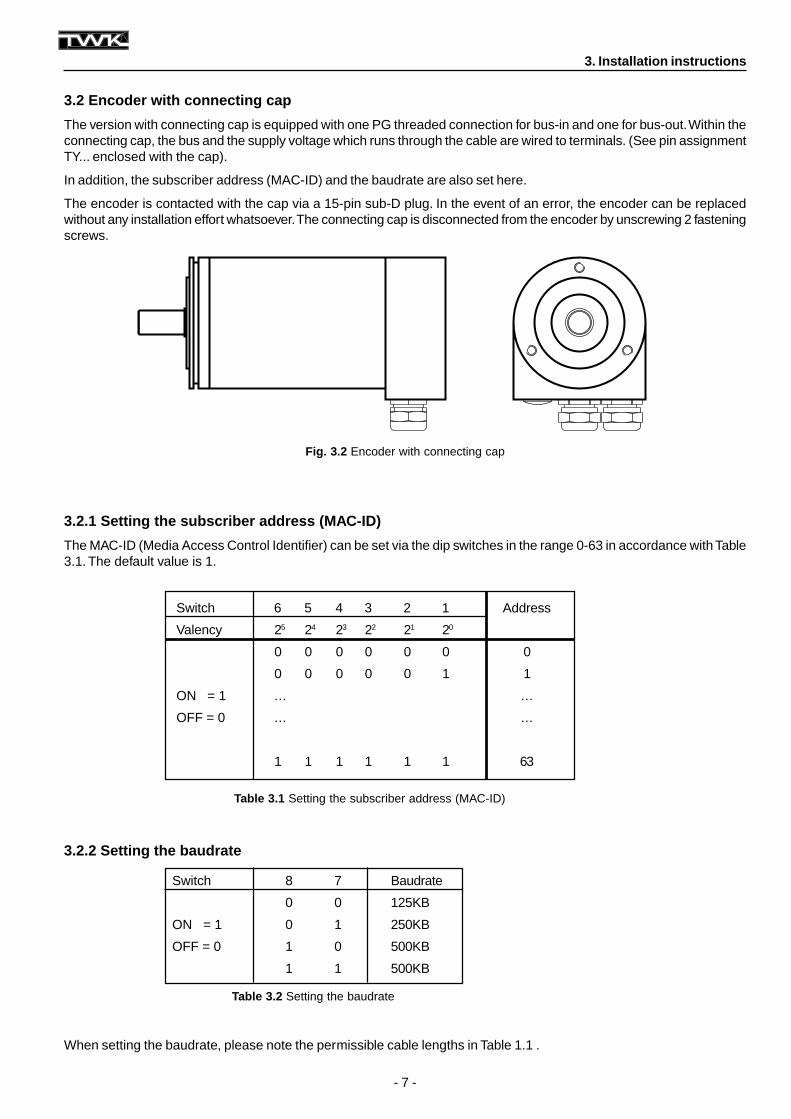
Fig. 3.2 Encoder with connecting cap
3. Installation instructions
3.2 Encoder with connecting cap
The version with connecting cap is equipped with one PG threaded connection for bus-in and one for bus-out. Within theconnecting cap, the bus and the supply voltage which runs through the cable are wired to terminals. (See pin assignmentTY... enclosed with the cap).
In addition, the subscriber address (MAC-ID) and the baudrate are also set here.
The encoder is contacted with the cap via a 15-pin sub-D plug. In the event of an error, the encoder can be replacedwithout any installation effort whatsoever. The connecting cap is disconnected from the encoder by unscrewing 2 fasteningscrews.
3.2.1 Setting the subscriber address (MAC-ID)
The MAC-ID (Media Access Control Identifier) can be set via the dip switches in the range 0-63 in accordance with Table3.1. The default value is 1.
When setting the baudrate, please note the permissible cable lengths in Table 1.1 .
Switch 8 7 Baudrate
0 0 125KB
ON = 1 0 1 250KB
OFF = 0 1 0 500KB
1 1 500KB
Switch 6 5 4 3 2 1 Address
Valency 25 24 23 22 21 20
0 0 0 0 0 0 0
0 0 0 0 0 1 1
ON = 1 ... ...
OFF = 0 ... ...
1 1 1 1 1 1 63
- 8 -
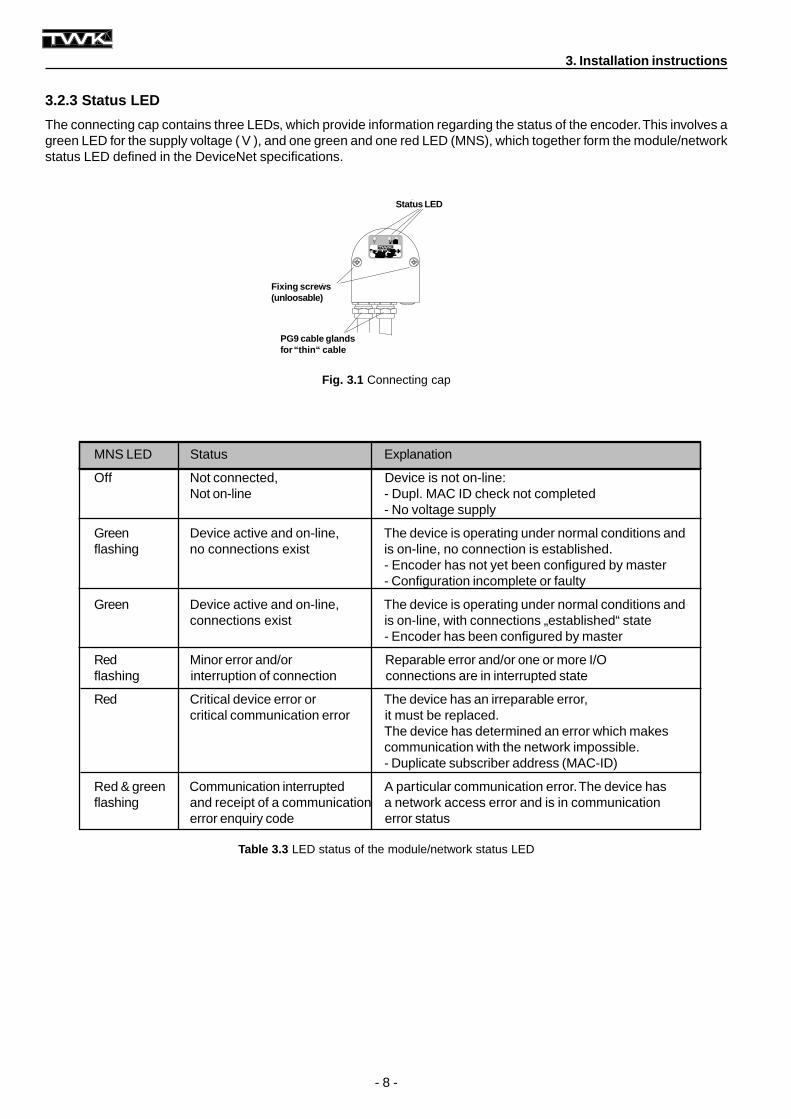
Fig. 3.1 Connecting cap
3.2.3 Status LED
The connecting cap contains three LEDs, which provide information regarding the status of the encoder. This involves agreen LED for the supply voltage ( V ), and one green and one red LED (MNS), which together form the module/networkstatus LED defined in the DeviceNet specifications.
Table 3.3 LED status of the module/network status LED
3. Installation instructions
PG9 cable glandsfor “thin“ cable
Fixing screws(unloosable)
Status LED
MNS LED Status Explanation
Off Not connected, Device is not on-line:Not on-line - Dupl. MAC ID check not completed
- No voltage supply
Green Device active and on-line, The device is operating under normal conditions andflashing no connections exist is on-line, no connection is established.
- Encoder has not yet been configured by master- Configuration incomplete or faulty
Green Device active and on-line, The device is operating under normal conditions andconnections exist is on-line, with connections „established“ state
- Encoder has been configured by master
Red Minor error and/or Reparable error and/or one or more I/Oflashing interruption of connection connections are in interrupted state
Red Critical device error or The device has an irreparable error,critical communication error it must be replaced.
The device has determined an error which makescommunication with the network impossible.- Duplicate subscriber address (MAC-ID)
Red & green Communication interrupted A particular communication error. The device hasflashing and receipt of a communication a network access error and is in communication
error enquiry code error status
- 9 -
4. The encoder operating modes
The encoder operating modes determine the triggering of actual position value recording. The user can choose betweenfour different operating modes:
1. Polling mode2. Bit strobed mode3. Change-of-state mode4. Cyclical mode
In addition, several operating modes can be set at the same time.
4.1 Polling mode
The standard operating mode in the master-slave system is the polling mode. In this case, the master interrogates allsubscribers cyclically. In this manner, all output data are transferred to the slaves, and all input data from the slaves areread in one scan. The time between two scans can generally be set in the master.
The encoder therefore provides its input data when cyclically requested (poll command) by the master.
4.2 Bit strobed mode
If one wishes to address certain (or all) slaves at a certain point in time, the bit strobed mode is used.
If the encoder is operated in this mode, it transmits its input data as a reaction to the bit strobe command.
4.3 Change-of-state mode
If a subscriber is only intended to transfer its input values if these have changed, it is operated in change-of-state mode.In this operating mode, a heartbeat rate can additionally be set. Following the expiry of an internal time, the subscribertransmits new input data, even if these have not changed.
In this operating mode, the encoder provides its position data in the event of a change and following the expiry of theheartbeat rate. The heartbeat rate can be set within the range 2 - 65535 ms in steps of 2 ms. (In this case, the Allen-Bradley DeviceNet Manager merely permits a minimum of 48 ms).
In this operating mode, a time delay can additionally be set within the range 2 - 65535 ms (production inhibit time). Thenew actual position value is then only transferred to the master following the expiry of this time.
4.4 Cyclic mode
In cyclic mode, the subscriber provides its input data in a fixed temporal cycle. This send rate can be set in eachsubscriber.
The cyclic mode is therefore a change-of-state mode which merely transmits the input data cyclically, and not in theevent of a change in values.
Strictly speaking, this is not a separate operating mode, but a variation of the change-of-state mode. For this reason, werefer to change-of-state / cyclic mode.
4. The encoder operating modes
- 10 -
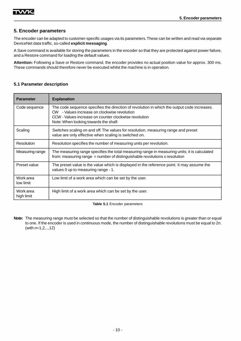
5.1 Parameter description
5. Encoder parameters
The encoder can be adapted to customer-specific usages via its parameters. These can be written and read via separateDeviceNet data traffic, so-called explicit messaging .
A Save command is available for storing the parameters in the encoder so that they are protected against power failure,and a Restore command for loading the default values.
Attention: Following a Save or Restore command, the encoder provides no actual position value for approx. 300 ms.These commands should therefore never be executed whilst the machine is in operation.
Parameter Explanation
Code sequence The code sequence specifies the direction of revolution in which the output code increases.CW - Values increase on clockwise revolutionCCW - Values increase on counter clockwise revolutionNote: When looking towards the shaft
Scaling Switches scaling on and off. The values for resolution, measuring range and presetvalue are only effective when scaling is switched on.
Resolution Resolution specifies the number of measuring units per revolution.
Measuring range The measuring range specifies the total measuring range in measuring units; it is calculatedfrom: measuring range = number of distinguishable revolutions x resolution
Preset value The preset value is the value which is displayed in the reference point. It may assume thevalues 0 up to measuring range - 1.
Work area Low limit of a work area which can be set by the user.low limit
Work area High limit of a work area which can be set by the user.high limit
Table 5.1 Encoder parameters
Note: The measuring range must be selected so that the number of distinguishable revolutions is greater than or equalto one. If the encoder is used in continuous mode, the number of distinguishable revolutions must be equal to 2n.(with n=1,2,..,12)
5. Encoder parameters
- 11 -
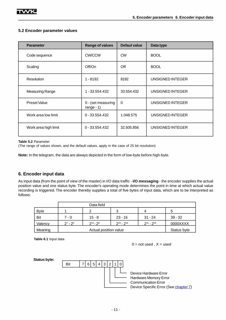
Table 5.2 Parameter(The range of values shown, and the default values, apply in the case of 25 bit resolution)
Table 6.1 Input data
0 = not used , X = used
5.2 Encoder parameter values
Parameter Range of values Defaul value Data type
Code sequence CW/CCW CW BOOL
Scaling Off/On Off BOOL
Resolution 1 - 8192 8192 UNSIGNED INTEGER
Measuring Range 1 - 33.554.432 33.554.432 UNSIGNED INTEGER
Preset Value 0 - (set measuring 0 UNSIGNED INTEGERrange - 1)
Work area low limit 0 - 33.554.432 1.048.575 UNSIGNED INTEGER
Work area high limit 0 - 33.554.432 32.505.856 UNSIGNED INTEGER
Status byte:Bit 7 6 5 4 3 2 1 0
Device Hardware ErrorHardware Memory ErrorCommunication ErrorDevice Specific Error (See chapter 7)
6. Encoder input data
As input data (from the point of view of the master) in I/O data traffic - I/O messaging - the encoder supplies the actualposition value and one status byte. The encoder’s operating mode determines the point in time at which actual valuerecording is triggered. The encoder thereby supplies a total of five bytes of input data, which are to be interpreted asfollows:
5. Encoder parameters 6. Encoder input data
Note: In the telegram, the data are always depicted in the form of low-byte before high-byte.
Data field
Byte 1 2 3 4 5
Bit 7 - 0 15 - 8 23 - 16 31 - 24 39 - 32
Valency 27 - 20 215 - 28 223 - 216 231 - 224 0000XXXX
Meaning Actual position value Status byte
- 12 -
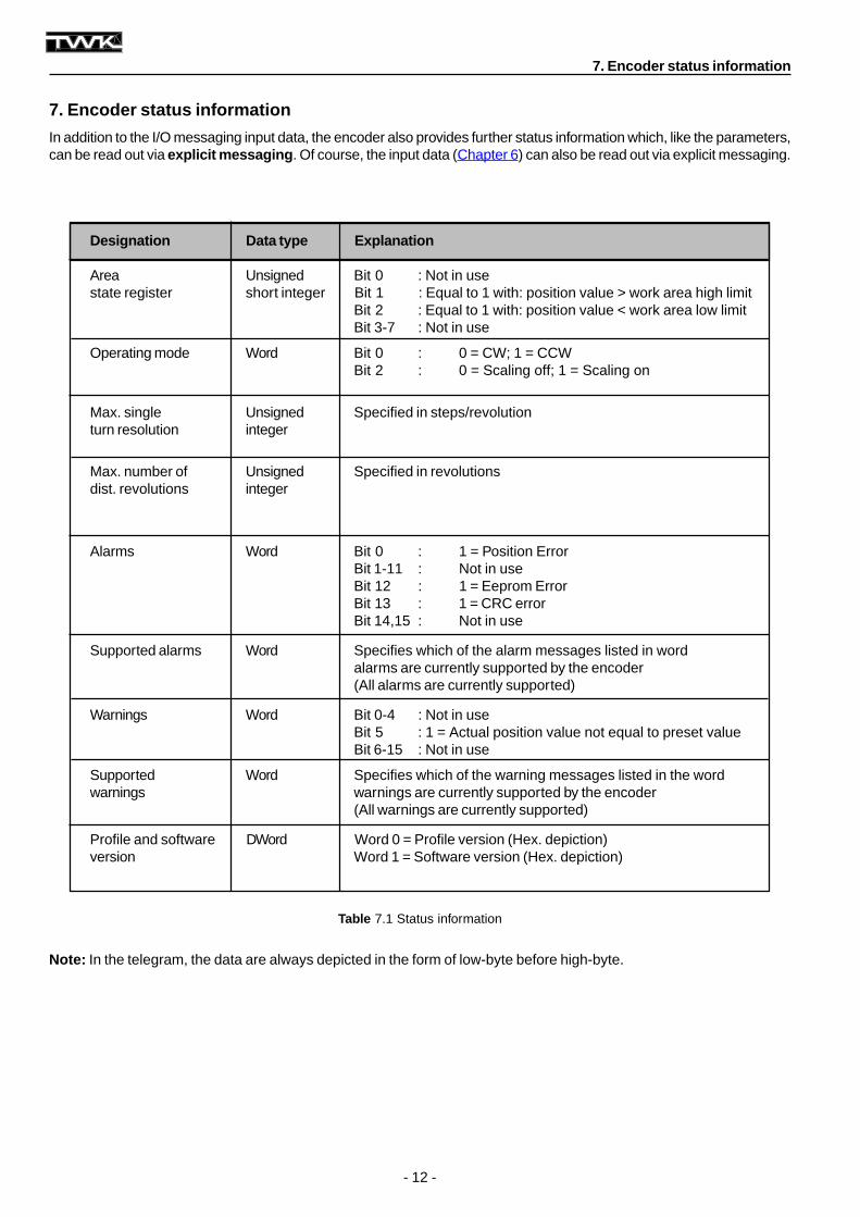
Table 7.1 Status information
7. Encoder status information
In addition to the I/O messaging input data, the encoder also provides further status information which, like the parameters,can be read out via explicit messaging . Of course, the input data (Chapter 6) can also be read out via explicit messaging.
Designation Data type Explanation
Area Unsigned Bit 0 : Not in usestate register short integer Bit 1 : Equal to 1 with: position value > work area high limit
Bit 2 : Equal to 1 with: position value < work area low limitBit 3-7 : Not in use
Operating mode Word Bit 0 : 0 = CW; 1 = CCWBit 2 : 0 = Scaling off; 1 = Scaling on
Max. single Unsigned Specified in steps/revolutionturn resolution integer
Max. number of Unsigned Specified in revolutionsdist. revolutions integer
Alarms Word Bit 0 : 1 = Position ErrorBit 1-11 : Not in useBit 12 : 1 = Eeprom ErrorBit 13 : 1 = CRC errorBit 14,15 : Not in use
Supported alarms Word Specifies which of the alarm messages listed in wordalarms are currently supported by the encoder(All alarms are currently supported)
Warnings Word Bit 0-4 : Not in useBit 5 : 1 = Actual position value not equal to preset valueBit 6-15 : Not in use
Supported Word Specifies which of the warning messages listed in the wordwarnings warnings are currently supported by the encoder
(All warnings are currently supported)
Profile and software DWord Word 0 = Profile version (Hex. depiction)version Word 1 = Software version (Hex. depiction)
Note: In the telegram, the data are always depicted in the form of low-byte before high-byte.
7. Encoder status information
- 13 -
8. The DeviceNet layer 7 protocol
Note: In order to commence the operation of the encoder on an Allen-Bradley SPS with the aid of the DeviceNetManager or RS-Networx, knowledge of this chapter is not absolutely mandatory. In this case, continue with Chapter 9or Chapter 10.
8.1 DeviceNet object structure
In the case of DeviceNet, layer 7 of the ISO/OSI communication model is structured in a very object-oriented manner.Each subscriber is comprised of a certain set of objects. Each object contains attributes (data) and services (functions)of a very specific component of the subscriber. In turn, objects which represent the same system components arecomprised to form classes.
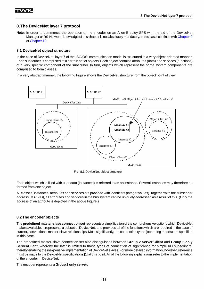
In a very abstract manner, the following Figure shows the DeviceNet structure from the object point of view:
Each object which is filled with user data (instanced) is referred to as an instance. Several instances may therefore beformed from one object.
All classes, instances, attributes and services are provided with identifiers (integer values). Together with the subscriberaddress (MAC-ID), all attributes and services in the bus system can be uniquely addressed as a result of this. (Only theaddress of an attribute is depicted in the above Figure.)
8.2 The encoder objects
The predefined master-slave connection set represents a simplification of the comprehensive options which DeviceNetmakes available. It represents a subset of DeviceNet, and provides all of the functions which are required in the case ofcurrent, conventional master-slave relationships. Most significantly, the connection types (operating modes) are specifiedin this case.
The predefined master-slave connection set also distinguishes between Group 2 Server/Client and Group 2 onlyServer/Client , whereby the later is limited to those types of connection of significance for simple I/O subscribers,thereby enabling the inexpensive implementation of DeviceNet slaves. For more detailed information, however, referencemust be made to the DeviceNet specifications |1| at this point. All of the following explanations refer to the implementationof the encoder in DeviceNet.
The encoder represents a Group 2 only server .
8. The DeviceNet layer 7 protocol
DeviceNet Link
MAC ID #1 MAC ID #2
MAC ID #3
MAC ID #4
MAC ID #4:Object Class #5:Instance #2:Attribute #1
Object Class #5
Object Class #7
Instance #1
Instance #2
Instance #1
Object Class #5
Instance #1
Attribute #1
Attribute #2
Fig. 8.1 DeviceNet object structure
- 14 -
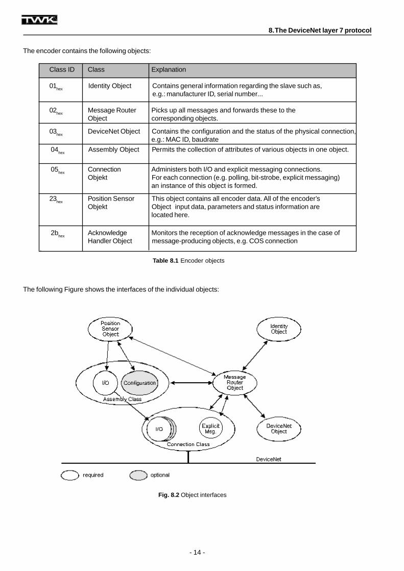
The following Figure shows the interfaces of the individual objects:
8. The DeviceNet layer 7 protocol
The encoder contains the following objects:
Class ID Class Explanation
01hex Identity Object Contains general information regarding the slave such as,e.g.: manufacturer ID, serial number...
02hex Message Router Picks up all messages and forwards these to theObject corresponding objects.
03hex
DeviceNet Object Contains the configuration and the status of the physical connection,e.g.: MAC ID, baudrate
04hex
Assembly Object Permits the collection of attributes of various objects in one object.
05hex
Connection Administers both I/O and explicit messaging connections.Objekt For each connection (e.g. polling, bit-strobe, explicit messaging)
an instance of this object is formed.
23hex
Position Sensor This object contains all encoder data. All of the encoder’sObjekt Object input data, parameters and status information are
located here.
2bhex
Acknowledge Monitors the reception of acknowledge messages in the case ofHandler Object message-producing objects, e.g. COS connection
.
Fig. 8.2 Object interfaces
Table 8.1 Encoder objects
- 15 -
8.2.1 Identity Object
Class Code 01hex
Class AttributesNot supported
Instance Attributes
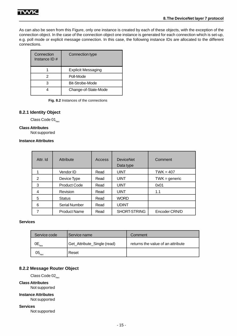
As can also be seen from this Figure, only one instance is created by each of these objects, with the exception of theconnection object. In the case of the connection object one instance is generated for each connection which is set-up,e.g. poll mode or explicit message connection. In this case, the following instance IDs are allocated to the differentconnections.
8.2.2 Message Router Object
Class Code 02hex
Class AttributesNot supported
Instance AttributesNot supported
ServicesNot supported
Services
Service code Service name Comment
0Ehex
Get_Attribute_Single (read) returns the value of an attribute
05hex
Reset
Attr. Id Attribute Access DeviceNet Comment
Data type
1 Vendor ID Read UINT TWK = 407
2 Device Type Read UINT TWK = generic
3 Product Code Read UINT 0x01
4 Revision Read UINT 1.1
5 Status Read WORD
6 Serial Number Read UDINT
7 Product Name Read SHORT-STRING Encoder CRN/D
8. The DeviceNet layer 7 protocol
Fig. 8.2 Instances of the connections
Connection Connection typeInstance ID #
1 Explicit Messaging
2 Poll-Mode
3 Bit-Strobe-Mode
4 Change-of-State-Mode
- 16 -
8.2.3 DeviceNet Object
Class Code 03hex
Class Attributes
8.2.4 Assembly Object
Class Code 04hex
Class AttributesNot supported
Services
* only with plug-in version
Instance Attributes
Attr. Id Attribute Access DeviceNet CommentData type
1 Revision Read UINT Revision = 002
Attr. Id Attribute Access DeviceNet RemarksData type
1 MAC ID Read/Write* USINT Revision = 002
2 Baud Rate Read/Write* USINT Range 0-2
3 BOI Read BOOL Value = 0
4 Bus-Off Counter Read/Write USINT
5 Allocation Information Read STRUCT of: Allocation Choice ByteBYTE Master’s MAC IDUSINT
Service code Service name Comment
0Ehex Get_Attribute_Single (Read) Returns the value of an attribute
10hex
Set_Attribute_Single (Write) Changes the value of an attribute
4B
hexAllocate_Master/Slave_Connection_ Set Predefined Master/Slave Connection Set
is requested
4Chex
Release_Group_2_Connection_Set Connections of the Predefined Master/Slave Connection Set are cancelled
Instance Attributes
Attr. Id Attribute Access DeviceNet RemarksData type
3 Data Read/Write ARRAY
8. The DeviceNet layer 7 protocol
- 17 -
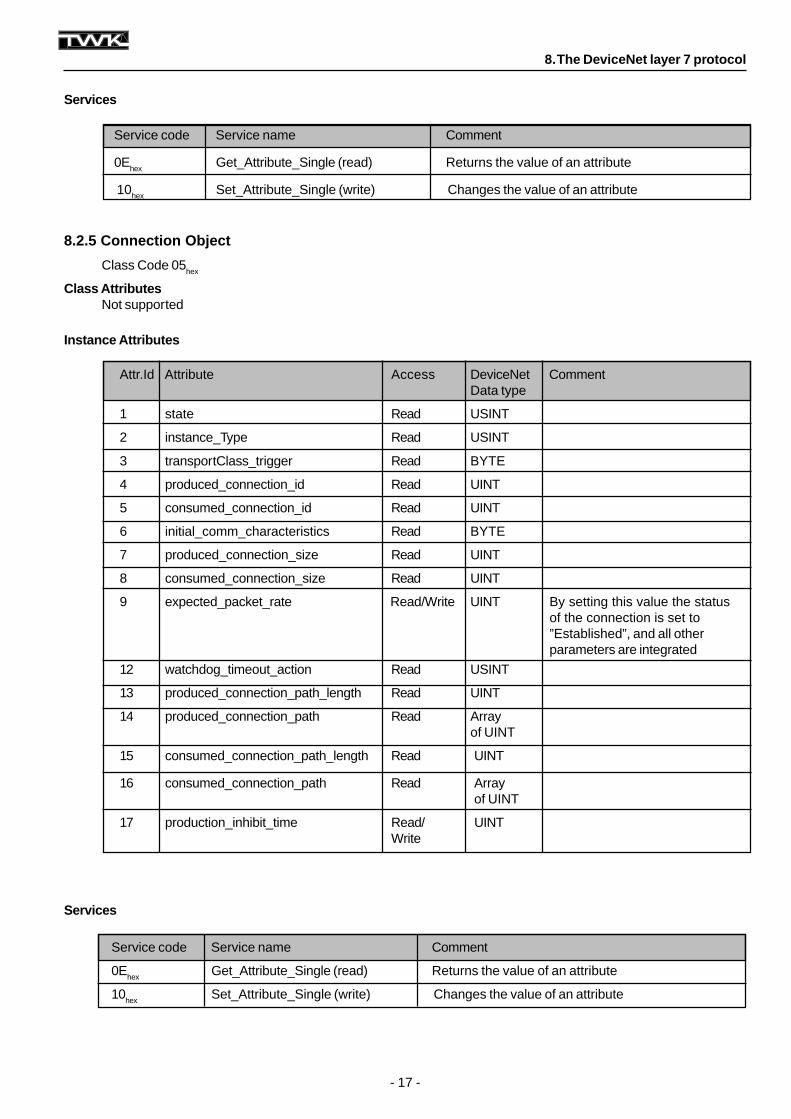
8.2.5 Connection Object
Class Code 05hex
Class AttributesNot supported
Services
Instance Attributes
Services
Service code Service name Comment
0Ehex
Get_Attribute_Single (read) Returns the value of an attribute
10hex Set_Attribute_Single (write) Changes the value of an attribute
Attr.Id Attribute Access DeviceNet CommentData type
1 state Read USINT
2 instance_Type Read USINT
3 transportClass_trigger Read BYTE
4 produced_connection_id Read UINT
5 consumed_connection_id Read UINT
6 initial_comm_characteristics Read BYTE
7 produced_connection_size Read UINT
8 consumed_connection_size Read UINT
9 expected_packet_rate Read/Write UINT By setting this value the statusof the connection is set to”Established”, and all otherparameters are integrated
12 watchdog_timeout_action Read USINT
13 produced_connection_path_length Read UINT
14 produced_connection_path Read Arrayof UINT
15 consumed_connection_path_length Read UINT
16 consumed_connection_path Read Arrayof UINT
17 production_inhibit_time Read/ UINTWrite
Service code Service name Comment
0Ehex
Get_Attribute_Single (read) Returns the value of an attribute
10hex
Set_Attribute_Single (write) Changes the value of an attribute
8. The DeviceNet layer 7 protocol
- 18 -
Instance AttributesODVA specific Part:
Manufacturer specific Part:
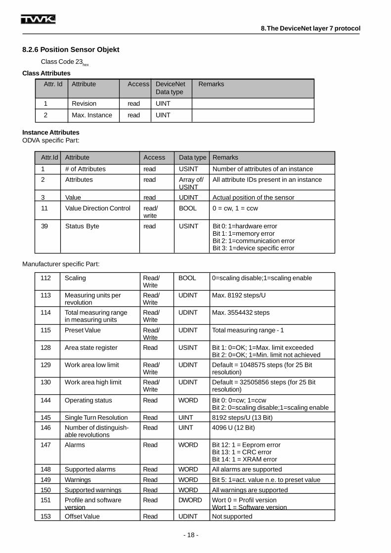
8.2.6 Position Sensor Objekt
Class Code 23hex
Class Attributes
Attr. Id Attribute Access DeviceNet RemarksData type
1 Revision read UINT
2 Max. Instance read UINT
Attr.Id Attribute Access Data type Remarks
1 # of Attributes read USINT Number of attributes of an instance
2 Attributes read Array of/ All attribute IDs present in an instanceUSINT
3 Value read UDINT Actual position of the sensor
11 Value Direction Control read/ BOOL 0 = cw, 1 = ccwwrite
39 Status Byte read USINT Bit 0: 1=hardware errorBit 1: 1=memory errorBit 2: 1=communication errorBit 3: 1=device specific error
112 Scaling Read/ BOOL 0=scaling disable;1=scaling enableWrite
113 Measuring units per Read/ UDINT Max. 8192 steps/Urevolution Write
114 Total measuring range Read/ UDINT Max. 3554432 stepsin measuring units Write
115 Preset Value Read/ UDINT Total measuring range - 1Write
128 Area state register Read USINT Bit 1: 0=OK; 1=Max. limit exceededBit 2: 0=OK; 1=Min. limit not achieved
129 Work area low limit Read/ UDINT Default = 1048575 steps (for 25 BitWrite resolution)
130 Work area high limit Read/ UDINT Default = 32505856 steps (for 25 BitWrite resolution)
144 Operating status Read WORD Bit 0: 0=cw; 1=ccwBit 2: 0=scaling disable;1=scaling enable
145 Single Turn Resolution Read UINT 8192 steps/U (13 Bit)
146 Number of distinguish- Read UINT 4096 U (12 Bit)able revolutions
147 Alarms Read WORD Bit 12: 1 = Eeprom errorBit 13: 1 = CRC errorBit 14: 1 = XRAM error
148 Supported alarms Read WORD All alarms are supported
149 Warnings Read WORD Bit 5: 1=act. value n.e. to preset value
150 Supported warnings Read WORD All warnings are supported
151 Profile and software Read DWORD Wort 0 = Profil versionversion Wort 1 = Software version
153 Offset Value Read UDINT Not supported
8. The DeviceNet layer 7 protocol
- 19 -
Services
Service code Service name Comment
0Ehex
Get_Attribute_Single (read) Returns the value of an attribute
10hex
Set_Attribute_Single (write) Changes the value of an attribute
15hex
Restore Writes default values into EEPROM
16hex
Save Writes non-volatile Attribute into EEPROM
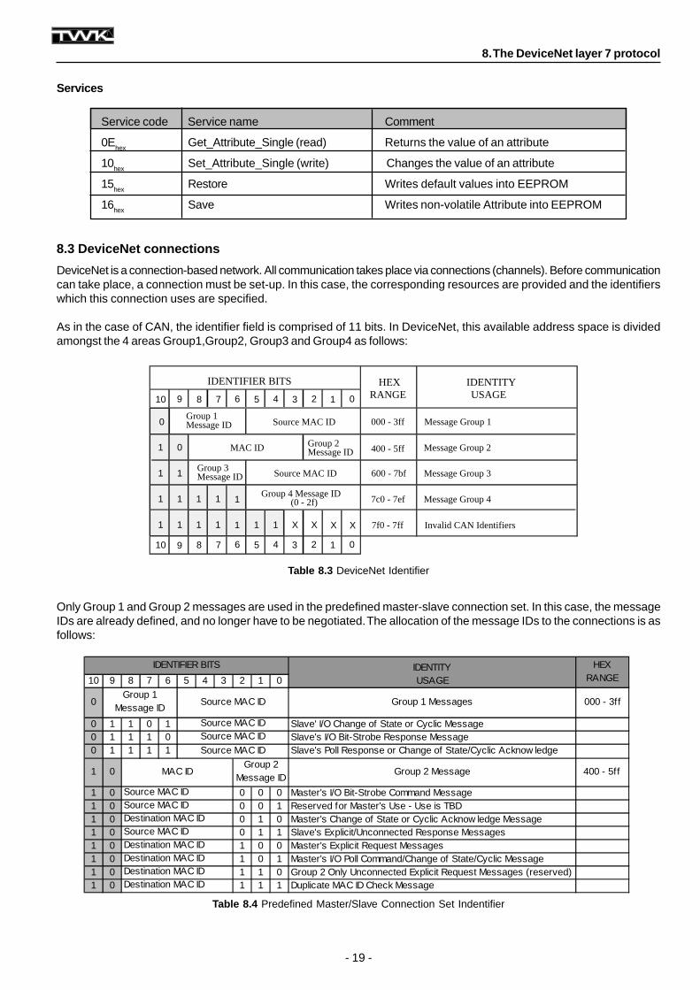
Table 8.4 Predefined Master/Slave Connection Set Indentifier
Table 8.3 DeviceNet Identifier
IDENTITY10 9 8 7 6 5 4 3 2 1 0 USAGE
0 Group 1 Messages 000 - 3ff
0 1 1 0 1 Slave' I/O Change of State or Cyclic Message0 1 1 1 0 Slave's I/O Bit-Strobe Response Message0 1 1 1 1 Slave's Poll Response or Change of State/Cyclic Acknow ledge
1 0 Group 2 Message 400 - 5ff
1 0 0 0 0 Master's I/O Bit-Strobe Command Message1 0 0 0 1 Reserved for Master's Use - Use is TBD1 0 0 1 0 Master's Change of State or Cyclic Acknow ledge Message1 0 0 1 1 Slave's Explicit/Unconnected Response Messages1 0 1 0 0 Master's Explicit Request Messages1 0 1 0 1 Master's I/O Poll Command/Change of State/Cyclic Message1 0 1 1 0 Group 2 Only Unconnected Explicit Request Messages (reserved)1 0 1 1 1 Duplicate MAC ID Check Message
IDENTIFIER BITS HEX RANGE
Group 1 Message ID
Source MAC ID
Source MAC IDSource MAC ID
Source MAC ID
MAC IDGroup 2
Message ID
Source MAC IDSource MAC IDDestination MAC IDSource MAC IDDestination MAC IDDestination MAC IDDestination MAC IDDestination MAC ID
8. The DeviceNet layer 7 protocol
8.3 DeviceNet connections
DeviceNet is a connection-based network. All communication takes place via connections (channels). Before communicationcan take place, a connection must be set-up. In this case, the corresponding resources are provided and the identifierswhich this connection uses are specified.
As in the case of CAN, the identifier field is comprised of 11 bits. In DeviceNet, this available address space is dividedamongst the 4 areas Group1,Group2, Group3 and Group4 as follows:
Only Group 1 and Group 2 messages are used in the predefined master-slave connection set. In this case, the messageIDs are already defined, and no longer have to be negotiated. The allocation of the message IDs to the connections is asfollows:
0 Source MAC ID 000 - 3ff
IDENTIFIER BITSUSAGE
IDENTITY
Group 1Message ID
RANGEHEX
Message Group 1
1 MAC ID Group 2Message ID
012345678910
012345678910
0 400 - 5ff Message Group 2
1 1Group 3Message ID Source MAC ID 600 - 7bf Message Group 3
1 1 1 1 1Group 4 Message ID
(0 - 2f) 7c0 - 7ef Message Group 4
1 1 1 1 1 1 1 X X X X 7f0 - 7ff Invalid CAN Identifiers
- 20 -
Allocation Choice Byte
7 6 5 4 3 2 1 0Reserved Acknowledge Cycle Change Reserved Bit Polled Explicit
Suppression of State Strobed Message
8. The DeviceNet layer 7 protocol
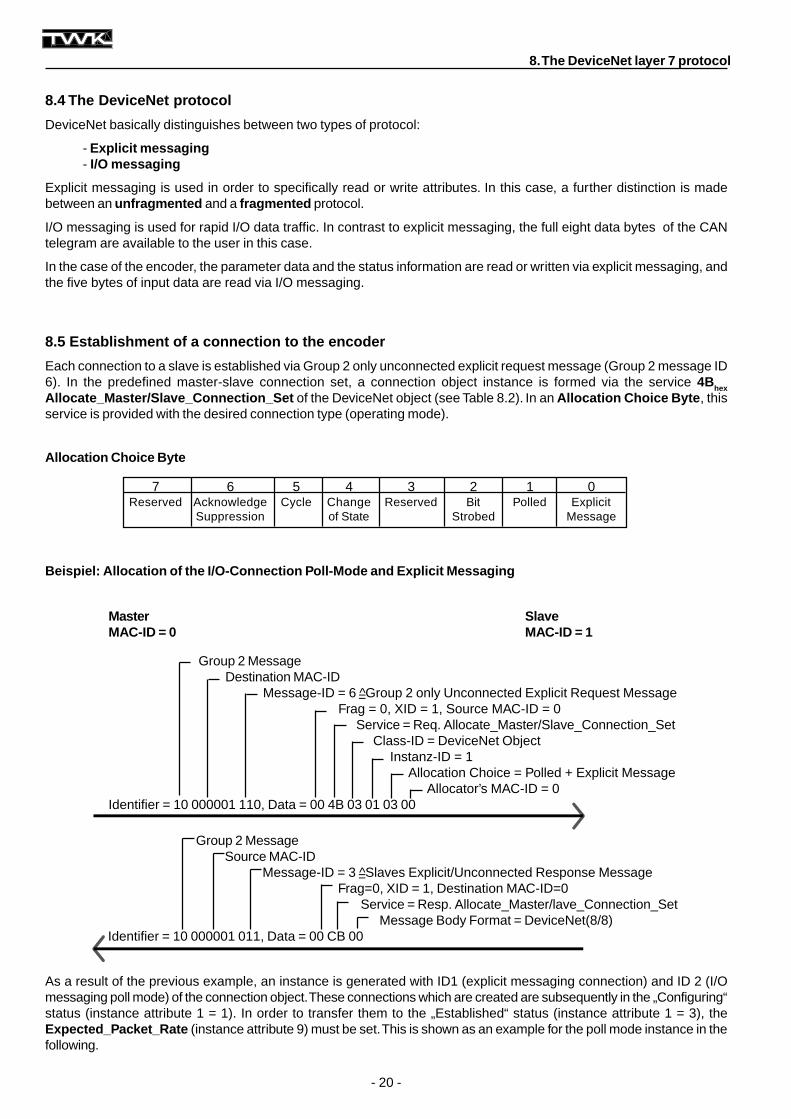
Beispiel: Allocation of the I/O-Connection Poll-Mode and Explicit Messaging
8.4 The DeviceNet protocol
DeviceNet basically distinguishes between two types of protocol:
- Explicit messaging- I/O messaging
Explicit messaging is used in order to specifically read or write attributes. In this case, a further distinction is madebetween an unfragmented and a fragmented protocol.
I/O messaging is used for rapid I/O data traffic. In contrast to explicit messaging, the full eight data bytes of the CANtelegram are available to the user in this case.
In the case of the encoder, the parameter data and the status information are read or written via explicit messaging, andthe five bytes of input data are read via I/O messaging.
8.5 Establishment of a connection to the encoder
Each connection to a slave is established via Group 2 only unconnected explicit request message (Group 2 message ID6). In the predefined master-slave connection set, a connection object instance is formed via the service 4Bhex
Allocate_Master/Slave_Connection_Set of the DeviceNet object (see Table 8.2). In an Allocation Choice Byte , thisservice is provided with the desired connection type (operating mode).
As a result of the previous example, an instance is generated with ID1 (explicit messaging connection) and ID 2 (I/Omessaging poll mode) of the connection object. These connections which are created are subsequently in the „Configuring“status (instance attribute 1 = 1). In order to transfer them to the „Established“ status (instance attribute 1 = 3), theExpected_Packet_Rate (instance attribute 9) must be set. This is shown as an example for the poll mode instance in thefollowing.
Group 2 MessageSource MAC-ID
Message-ID = 3 =̂ Slaves Explicit/Unconnected Response MessageFrag=0, XID = 1, Destination MAC-ID=0
Service = Resp. Allocate_Master/lave_Connection_SetMessage Body Format = DeviceNet(8/8)
Identifier = 10 000001 011, Data = 00 CB 00
Master S laveMAC-ID = 0 MAC-ID = 1
Group 2 MessageDestination MAC-ID
Message-ID = 6 =̂ Group 2 only Unconnected Explicit Request MessageFrag = 0, XID = 1, Source MAC-ID = 0
Service = Req. Allocate_Master/Slave_Connection_SetClass-ID = DeviceNet Object
Instanz-ID = 1Allocation Choice = Polled + Explicit Message
Allocator’s MAC-ID = 0Identifier = 10 000001 110, Data = 00 4B 03 01 03 00
- 21 -
Master S laveMAC-ID = 0 MAC-ID = 1
8. The DeviceNet layer 7 protocol
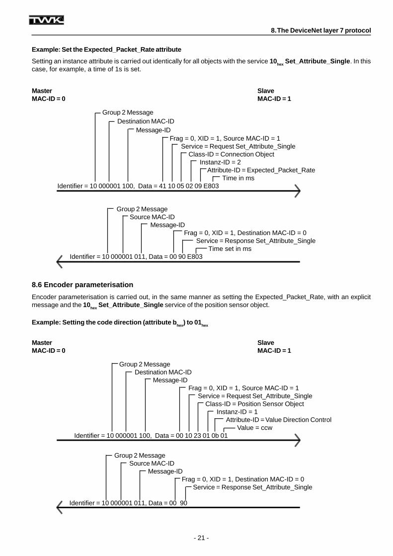
Example: Set the Expected_Packet_Rate attribute
Setting an instance attribute is carried out identically for all objects with the service 10hex Set_Attribute_Single . In thiscase, for example, a time of 1s is set.
8.6 Encoder parameterisation
Encoder parameterisation is carried out, in the same manner as setting the Expected_Packet_Rate, with an explicitmessage and the 10hex Set_Attribute_Single service of the position sensor object.
Example: Setting the code direction (attribute b hex) to 01 hex
Group 2 MessageDestination MAC-ID
Message-IDFrag = 0, XID = 1, Source MAC-ID = 1
Service = Request Set_Attribute_SingleClass-ID = Connection Object
Instanz-ID = 2Attribute-ID = Expected_Packet_Rate
Time in msIdentifier = 10 000001 100, Data = 41 10 05 02 09 E803
Group 2 MessageSource MAC-ID
Message-IDFrag = 0, XID = 1, Destination MAC-ID = 0
Service = Response Set_Attribute_SingleTime set in ms
Identifier = 10 000001 011, Data = 00 90 E803
Master S laveMAC-ID = 0 MAC-ID = 1
Group 2 MessageDestination MAC-ID
Message-IDFrag = 0, XID = 1, Source MAC-ID = 1
Service = Request Set_Attribute_SingleClass-ID = Position Sensor Object
Instanz-ID = 1Attribute-ID = Value Direction Control
Value = ccwIdentifier = 10 000001 100, Data = 00 10 23 01 0b 01
Group 2 MessageSource MAC-ID
Message-IDFrag = 0, XID = 1, Destination MAC-ID = 0
Service = Response Set_Attribute_Single
Identifier = 10 000001 011, Data = 00 90
- 22 -
Example: Reading Attribute 80 hex Area State Register
8. The DeviceNet layer 7 protocol
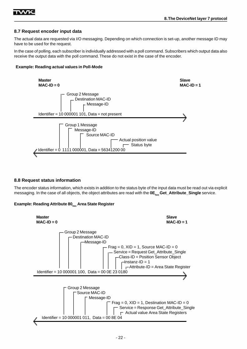
8.7 Request encoder input data
The actual data are requested via I/O messaging. Depending on which connection is set-up, another message ID mayhave to be used for the request.
In the case of polling, each subscriber is individually addressed with a poll command. Subscribers which output data alsoreceive the output data with the poll command. These do not exist in the case of the encoder.
8.8 Request status information
The encoder status information, which exists in addition to the status byte of the input data must be read out via explicitmessaging. In the case of all objects, the object attributes are read with the 0Ehex Get_Attribute_Single service.
Example: Reading actual values in Poll-Mode
Group 1 MessageMessage-ID
Source MAC-IDActual position value
Status byteIdentifier = 0 1111 000001, Data = 56341200 00
Master S laveMAC-ID = 0 MAC-ID = 1
Group 2 MessageDestination MAC-ID
Message-ID
Identifier = 10 000001 101, Data = not present
Master S laveMAC-ID = 0 MAC-ID = 1
Group 2 MessageDestination MAC-ID
Message-IDFrag = 0, XID = 1, Source MAC-ID = 0
Service = Request Get_Attribute_SingleClass-ID = Position Sensor Object
Instanz-ID = 1Attribute-ID = Area State Register
Identifier = 10 000001 100, Data = 00 0E 23 01 80
Group 2 MessageSource MAC-ID
Message-IDFrag = 0, XID = 1, Destination MAC-ID = 0
Service = Response Get_Attribute_SingleActual value Area State Registers
Identifier = 10 000001 011, Data = 00 8E 04
- 23 -
8. The DeviceNet layer 7 protocol
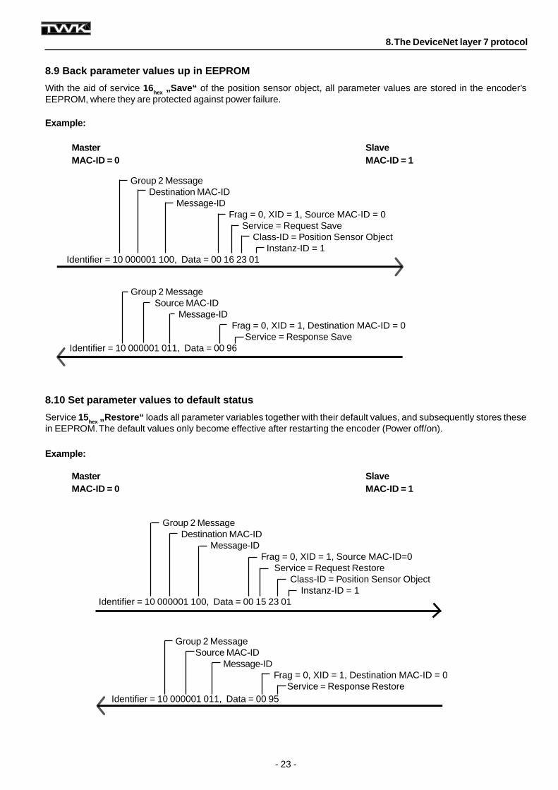
8.9 Back parameter values up in EEPROM
With the aid of service 16hex „Save“ of the position sensor object, all parameter values are stored in the encoder’sEEPROM, where they are protected against power failure.
8.10 Set parameter values to default status
Service 15hex „Restore“ loads all parameter variables together with their default values, and subsequently stores thesein EEPROM. The default values only become effective after restarting the encoder (Power off/on).
Example:
Master S laveMAC-ID = 0 MAC-ID = 1
Example:
Master S laveMAC-ID = 0 MAC-ID = 1
Group 2 MessageDestination MAC-ID
Message-IDFrag = 0, XID = 1, Source MAC-ID=0
Service = Request RestoreClass-ID = Position Sensor Object
Instanz-ID = 1Identifier = 10 000001 100, Data = 00 15 23 01
Group 2 MessageDestination MAC-ID
Message-IDFrag = 0, XID = 1, Source MAC-ID = 0
Service = Request SaveClass-ID = Position Sensor Object
Instanz-ID = 1Identifier = 10 000001 100, Data = 00 16 23 01
Group 2 MessageSource MAC-ID
Message-IDFrag = 0, XID = 1, Destination MAC-ID = 0
Service = Response SaveIdentifier = 10 000001 011, Data = 00 96
Group 2 MessageSource MAC-ID
Message-IDFrag = 0, XID = 1, Destination MAC-ID = 0
Service = Response RestoreIdentifier = 10 000001 011, Data = 00 95
- 24 -
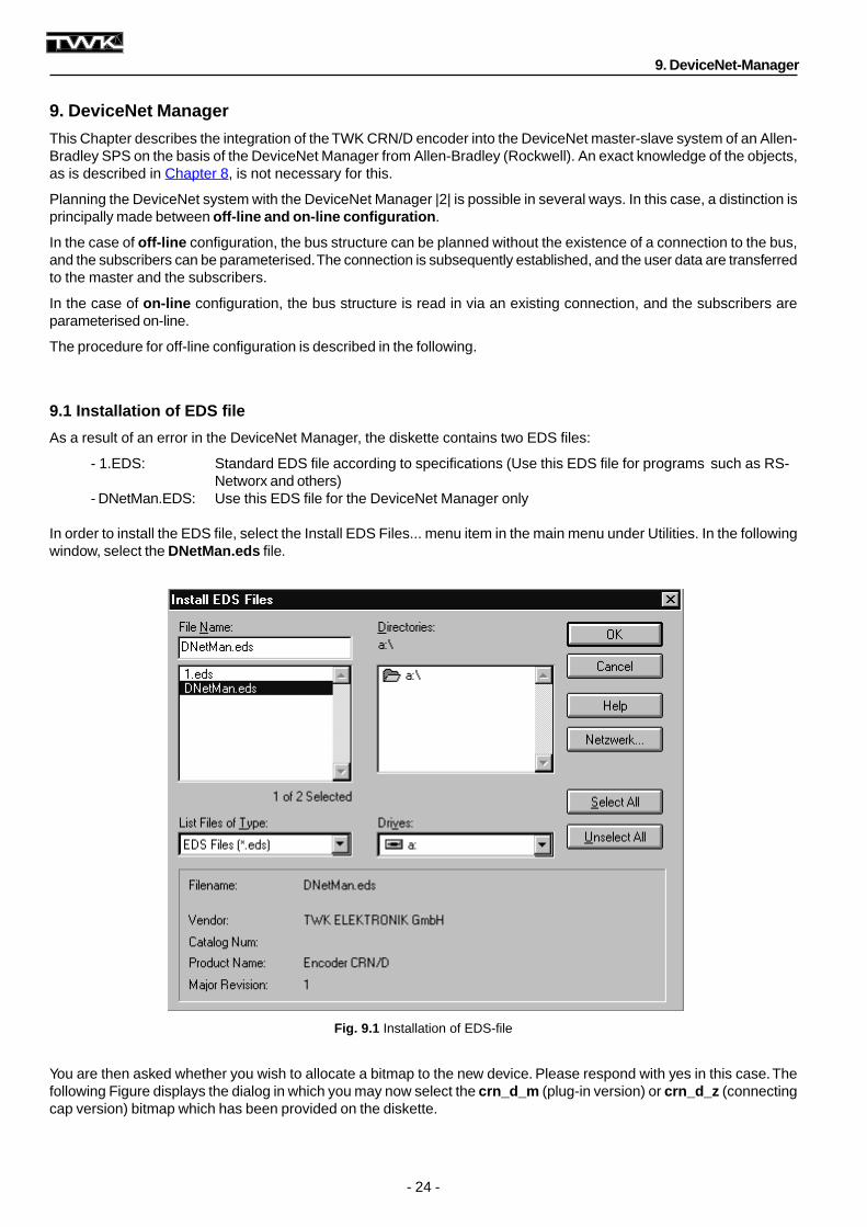
Fig. 9.1 Installation of EDS-file
9. DeviceNet Manager
This Chapter describes the integration of the TWK CRN/D encoder into the DeviceNet master-slave system of an Allen-Bradley SPS on the basis of the DeviceNet Manager from Allen-Bradley (Rockwell). An exact knowledge of the objects,as is described in Chapter 8, is not necessary for this.
Planning the DeviceNet system with the DeviceNet Manager |2| is possible in several ways. In this case, a distinction isprincipally made between off-line and on-line configuration .
In the case of off-line configuration, the bus structure can be planned without the existence of a connection to the bus,and the subscribers can be parameterised. The connection is subsequently established, and the user data are transferredto the master and the subscribers.
In the case of on-line configuration, the bus structure is read in via an existing connection, and the subscribers areparameterised on-line.
The procedure for off-line configuration is described in the following.
9.1 Installation of EDS file
As a result of an error in the DeviceNet Manager, the diskette contains two EDS files:
- 1.EDS: Standard EDS file according to specifications (Use this EDS file for programs such as RS-Networx and others)
- DNetMan.EDS: Use this EDS file for the DeviceNet Manager only
In order to install the EDS file, select the Install EDS Files... menu item in the main menu under Utilities. In the followingwindow, select the DNetMan.eds file.
You are then asked whether you wish to allocate a bitmap to the new device. Please respond with yes in this case. Thefollowing Figure displays the dialog in which you may now select the crn_d_m (plug-in version) or crn_d_z (connectingcap version) bitmap which has been provided on the diskette.
9. DeviceNet-Manager
- 25 -
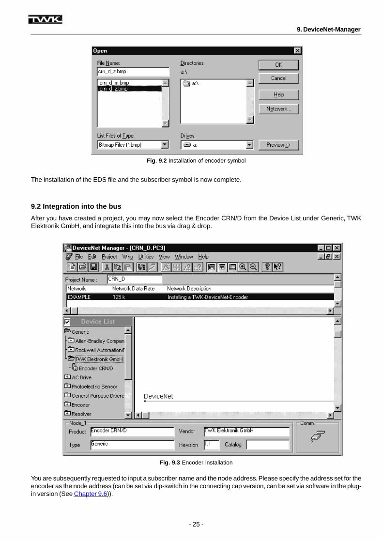
Fig. 9.2 Installation of encoder symbol
Fig. 9.3 Encoder installation
The installation of the EDS file and the subscriber symbol is now complete.
9.2 Integration into the bus
After you have created a project, you may now select the Encoder CRN/D from the Device List under Generic, TWKElektronik GmbH, and integrate this into the bus via drag & drop.
You are subsequently requested to input a subscriber name and the node address. Please specify the address set for theencoder as the node address (can be set via dip-switch in the connecting cap version, can be set via software in the plug-in version (See Chapter 9.6)).
9. DeviceNet-Manager
- 26 -
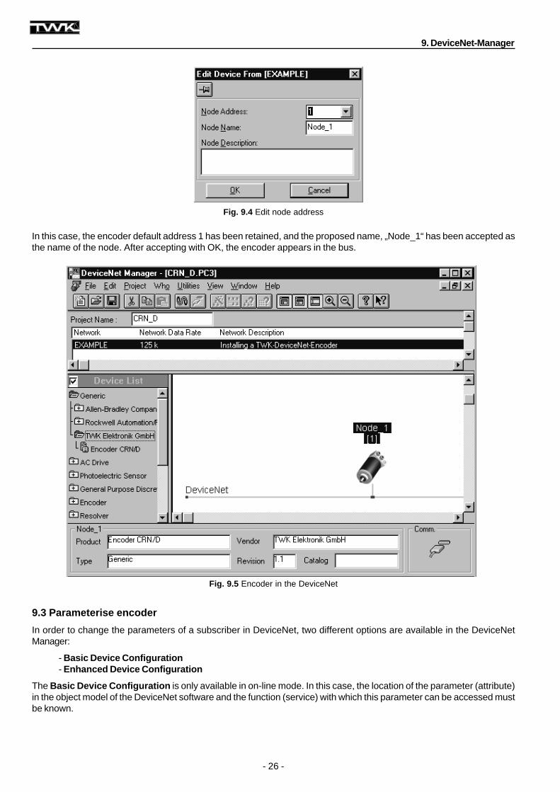
Fig. 9.5 Encoder in the DeviceNet
Fig. 9.4 Edit node address
In this case, the encoder default address 1 has been retained, and the proposed name, „Node_1“ has been accepted asthe name of the node. After accepting with OK, the encoder appears in the bus.
9.3 Parameterise encoder
In order to change the parameters of a subscriber in DeviceNet, two different options are available in the DeviceNetManager:
- Basic Device Configuration- Enhanced Device Configuration
The Basic Device Configuration is only available in on-line mode. In this case, the location of the parameter (attribute)in the object model of the DeviceNet software and the function (service) with which this parameter can be accessed mustbe known.
9. DeviceNet-Manager
- 27 -
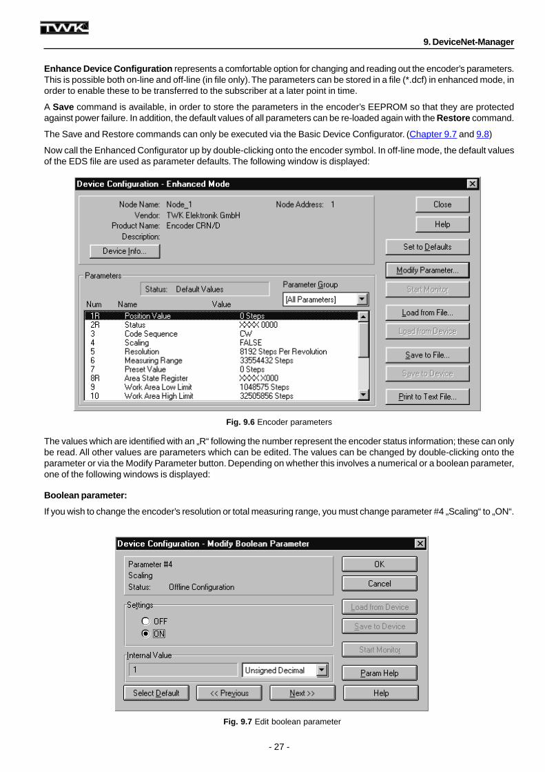
Fig. 9.6 Encoder parameters
Fig. 9.7 Edit boolean parameter
Enhance Device Configuration represents a comfortable option for changing and reading out the encoder’s parameters.This is possible both on-line and off-line (in file only). The parameters can be stored in a file (*.dcf) in enhanced mode, inorder to enable these to be transferred to the subscriber at a later point in time.
A Save command is available, in order to store the parameters in the encoder’s EEPROM so that they are protectedagainst power failure. In addition, the default values of all parameters can be re-loaded again with the Restore command.
The Save and Restore commands can only be executed via the Basic Device Configurator. (Chapter 9.7 and 9.8)
Now call the Enhanced Configurator up by double-clicking onto the encoder symbol. In off-line mode, the default valuesof the EDS file are used as parameter defaults. The following window is displayed:
The values which are identified with an „R“ following the number represent the encoder status information; these can onlybe read. All other values are parameters which can be edited. The values can be changed by double-clicking onto theparameter or via the Modify Parameter button. Depending on whether this involves a numerical or a boolean parameter,one of the following windows is displayed:
Boolean parameter:
If you wish to change the encoder’s resolution or total measuring range, you must change parameter #4 „Scaling“ to „ON“.
9. DeviceNet-Manager
- 28 -
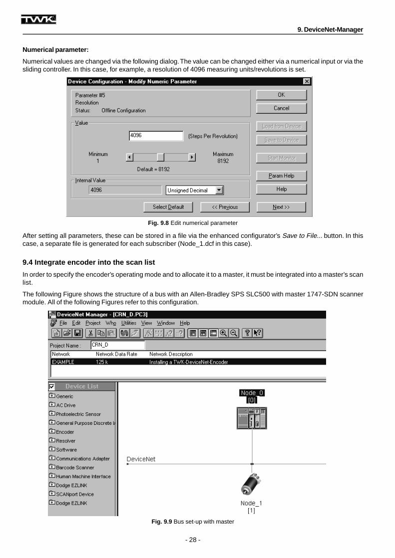
Fig. 9.8 Edit numerical parameter
Fig. 9.9 Bus set-up with master
Numerical parameter:
Numerical values are changed via the following dialog. The value can be changed either via a numerical input or via thesliding controller. In this case, for example, a resolution of 4096 measuring units/revolutions is set.
After setting all parameters, these can be stored in a file via the enhanced configurator’s Save to File... button. In thiscase, a separate file is generated for each subscriber (Node_1.dcf in this case).
9.4 Integrate encoder into the scan list
In order to specify the encoder’s operating mode and to allocate it to a master, it must be integrated into a master’s scanlist.
The following Figure shows the structure of a bus with an Allen-Bradley SPS SLC500 with master 1747-SDN scannermodule. All of the following Figures refer to this configuration.
9. DeviceNet-Manager
- 29 -
Fig. 9.10 Parameterise Master
Fig. 9.11 Scanlist of the master
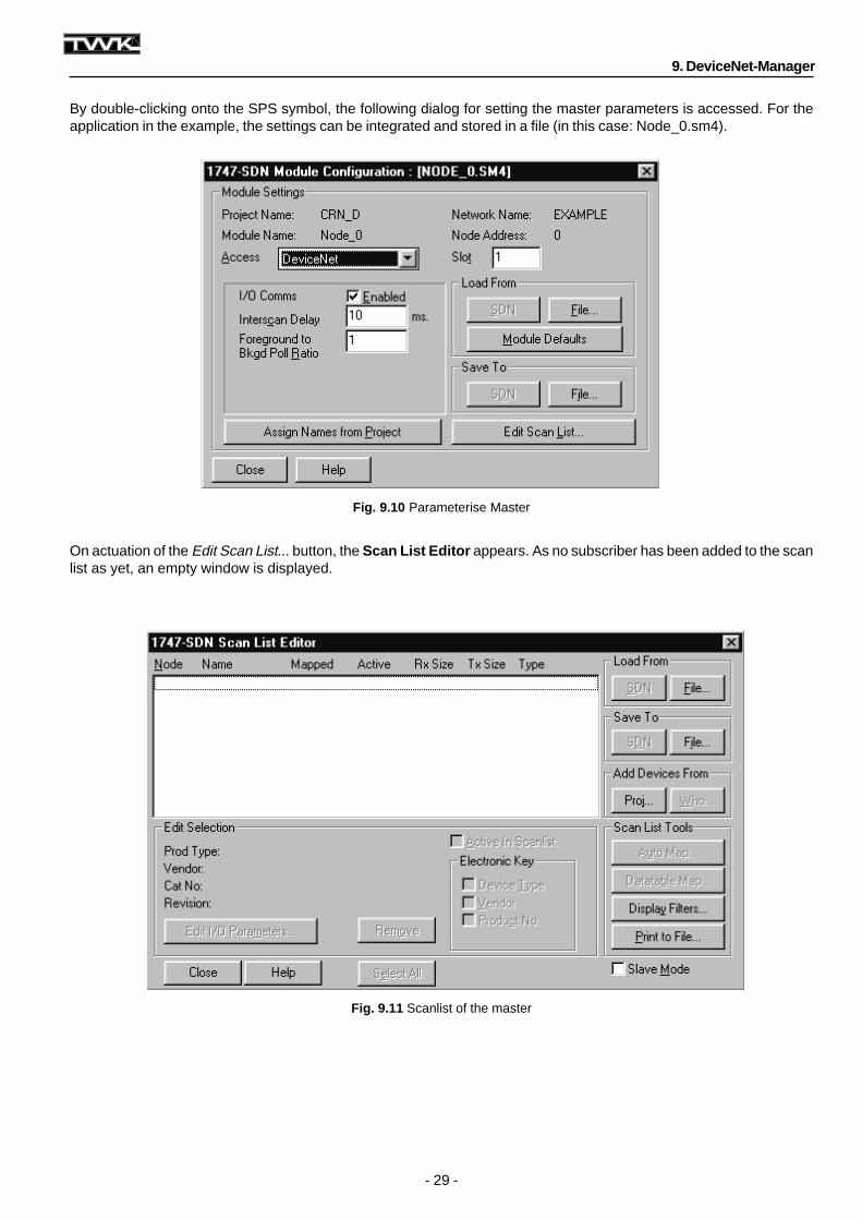
By double-clicking onto the SPS symbol, the following dialog for setting the master parameters is accessed. For theapplication in the example, the settings can be integrated and stored in a file (in this case: Node_0.sm4).
On actuation of the Edit Scan List... button, the Scan List Editor appears. As no subscriber has been added to the scanlist as yet, an empty window is displayed.
9. DeviceNet-Manager
- 30 -
Fig. 9.12 Add encoder to scan list
Fig. 9.13 Scanlist with encoder
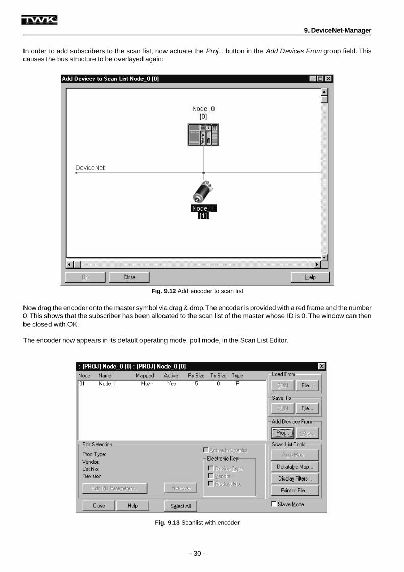
In order to add subscribers to the scan list, now actuate the Proj... button in the Add Devices From group field. Thiscauses the bus structure to be overlayed again:
Now drag the encoder onto the master symbol via drag & drop. The encoder is provided with a red frame and the number0. This shows that the subscriber has been allocated to the scan list of the master whose ID is 0. The window can thenbe closed with OK.
The encoder now appears in its default operating mode, poll mode, in the Scan List Editor.
9. DeviceNet-Manager
- 31 -
Fig. 9.14 Specify encoder operating mode
Fig. 9.15 Transfer scan list to the master
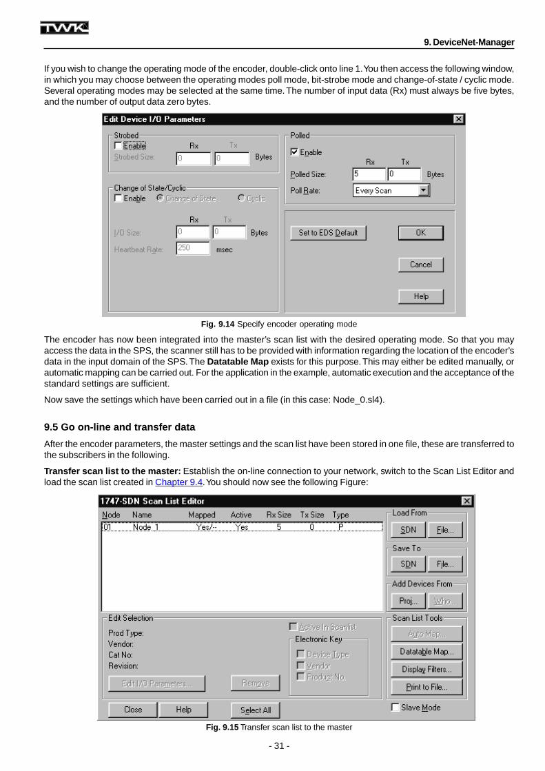
If you wish to change the operating mode of the encoder, double-click onto line 1. You then access the following window,in which you may choose between the operating modes poll mode, bit-strobe mode and change-of-state / cyclic mode.Several operating modes may be selected at the same time. The number of input data (Rx) must always be five bytes,and the number of output data zero bytes.
The encoder has now been integrated into the master’s scan list with the desired operating mode. So that you mayaccess the data in the SPS, the scanner still has to be provided with information regarding the location of the encoder’sdata in the input domain of the SPS. The Datatable Map exists for this purpose. This may either be edited manually, orautomatic mapping can be carried out. For the application in the example, automatic execution and the acceptance of thestandard settings are sufficient.
Now save the settings which have been carried out in a file (in this case: Node_0.sl4).
9.5 Go on-line and transfer data
After the encoder parameters, the master settings and the scan list have been stored in one file, these are transferred tothe subscribers in the following.
Transfer scan list to the master: Establish the on-line connection to your network, switch to the Scan List Editor andload the scan list created in Chapter 9.4. You should now see the following Figure:
9. DeviceNet-Manager
- 32 -
Fig. 9.16 Transmit parameters to the encoder
Now transfer the scan list to the scanner (master) with Save to SDN. In the case of a new project, specify All Records inthe following selection window.
Transfer parameters to the encoder:
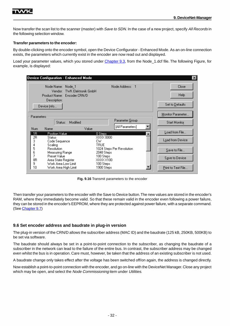
By double-clicking onto the encoder symbol, open the Device Configurator - Enhanced Mode. As an on-line connectionexists, the parameters which currently exist in the encoder are now read out and displayed.
Load your parameter values, which you stored under Chapter 9.3, from the Node_1.dcf file. The following Figure, forexample, is displayed:
Then transfer your parameters to the encoder with the Save to Device button. The new values are stored in the encoder’sRAM, where they immediately become valid. So that these remain valid in the encoder even following a power failure,they can be stored in the encoder’s EEPROM, where they are protected against power failure, with a separate command.(See Chapter 9.7)
9.6 Set encoder address and baudrate in plug-in version
The plug-in version of the CRN/D allows the subscriber address (MAC ID) and the baudrate (125 kB, 250KB, 500KB) tobe set via software.
The baudrate should always be set in a point-to-point connection to the subscriber, as changing the baudrate of asubscriber in the network can lead to the failure of the entire bus. In contrast, the subscriber address may be changedeven whilst the bus is in operation. Care must, however, be taken that the address of an existing subscriber is not used.
A baudrate change only takes effect after the voltage has been switched off/on again, the address is changed directly.
Now establish a point-to-point connection with the encoder, and go on-line with the DeviceNet Manager. Close any projectwhich may be open, and select the Node Commissioning item under Utilities.
9. DeviceNet-Manager
- 33 -
Fig. 9.17 Set node address
Fig. 9.18 Set baudrate
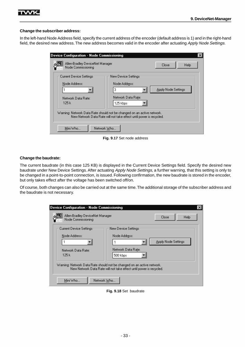
Change the subscriber address:
In the left-hand Node Address field, specify the current address of the encoder (default address is 1) and in the right-handfield, the desired new address. The new address becomes valid in the encoder after actuating Apply Node Settings.
Change the baudrate:
The current baudrate (in this case 125 KB) is displayed in the Current Device Settings field. Specify the desired newbaudrate under New Device Settings. After actuating Apply Node Settings, a further warning, that this setting is only tobe changed in a point-to-point connection, is issued. Following confirmation, the new baudrate is stored in the encoder,but only takes effect after the voltage has been switched off/on.
Of course, both changes can also be carried out at the same time. The additional storage of the subscriber address andthe baudrate is not necessary.
9. DeviceNet-Manager
- 34 -
Fig. 9.19 Store parameters in EEPROM
Fig. 9.20 Load parameter default values
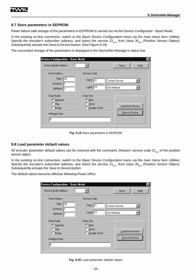
9.7 Store parameters in EEPROM
Power failure-safe storage of the parameters in EEPROM is carried out via the Device Configurator - Basic Mode.
In the existing on-line connection, switch to the Basic Device Configuration menu via the main menu item Utilities.Specify the encoder’s subscriber address, and select the service 22
dec. from class 35
dec (Position Sensor Object).
Subsequently actuate the Save to Device button. (See Figure 9.19)
The successful storage of the parameters is displayed in the DeviceNet Manager’s status line.
9.8 Load parameter default values
All encoder parameter default values can be restored with the command „Restore“ service code 21dec
of the positionsensor object.
In the existing on-line connection, switch to the Basic Device Configuration menu via the main menu item Utilities.Specify the encoder’s subscriber address, and select the service 21
dec. from class 35
dec (Position Sensor Object).
Subsequently actuate the Save to Device button.
The default values become effective following Power off/on.
9. DeviceNet-Manager
- 35 -
Fig. 9.21 Read serial number
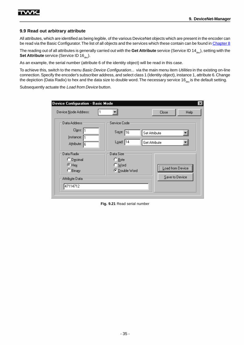
9.9 Read out arbitrary attribute
All attributes, which are identified as being legible, of the various DeviceNet objects which are present in the encoder canbe read via the Basic Configurator. The list of all objects and the services which these contain can be found in Chapter 8
The reading out of all attributes is generally carried out with the Get Attribute service (Service ID 14dec
), setting with theSet Attribute service (Service ID 16
dec).
As an example, the serial number (attribute 6 of the identity object) will be read in this case.
To achieve this, switch to the menu Basic Device Configuration... via the main menu item Utilities in the existing on-lineconnection. Specify the encoder’s subscriber address, and select class 1 (Identity object), instance 1, attribute 6. Changethe depiction (Data Radix) to hex and the data size to double word. The necessary service 16dec is the default setting.
Subsequently actuate the Load from Device button.
9. DeviceNet-Manager
- 36 -
Fig. 10.1 Installation of EDS-file
Fig. 10.2 Installation of encoder symbol
10. RS-Networx for DeviceNet
10. RS-Networx for DeviceNet
This Chapter describes the integration of the TWK CRN/D encoder into the DeviceNet master-slave system of an Allen-Bradley SPS on the basis of the planning tool, RS-Networx for DeviceNet. An exact knowledge of the objects, asdescribed in Chapter 8, is not necessary for this.
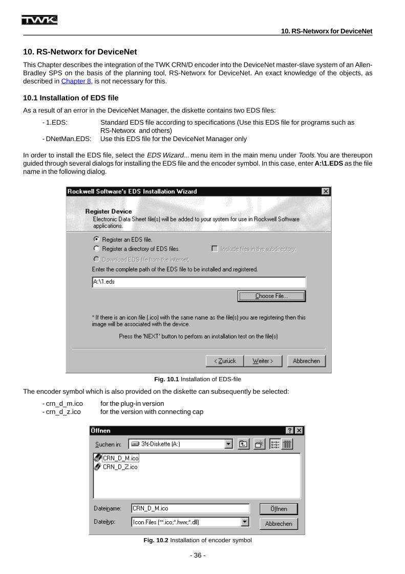
10.1 Installation of EDS file
As a result of an error in the DeviceNet Manager, the diskette contains two EDS files:
- 1.EDS: Standard EDS file according to specifications (Use this EDS file for programs such asRS-Networx and others)
- DNetMan.EDS: Use this EDS file for the DeviceNet Manager only
In order to install the EDS file, select the EDS Wizard... menu item in the main menu under Tools. You are thereuponguided through several dialogs for installing the EDS file and the encoder symbol. In this case, enter A:\1.EDS as the filename in the following dialog.
The encoder symbol which is also provided on the diskette can subsequently be selected:
- crn_d_m.ico for the plug-in version- crn_d_z.ico for the version with connecting cap
- 37 -
Fig. 10.3 Encoder integration
Fig. 10.4 Allocate subscriber address
10. RS-Networx for DeviceNet
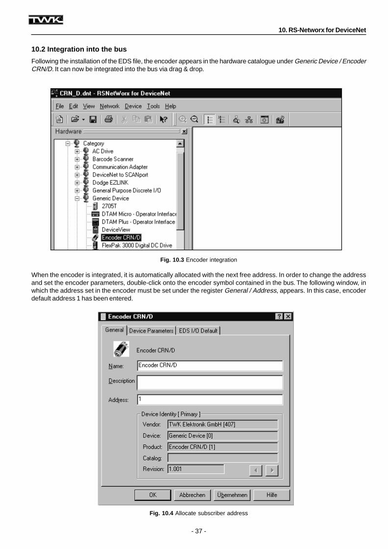
10.2 Integration into the bus
Following the installation of the EDS file, the encoder appears in the hardware catalogue under Generic Device / EncoderCRN/D. It can now be integrated into the bus via drag & drop.
When the encoder is integrated, it is automatically allocated with the next free address. In order to change the addressand set the encoder parameters, double-click onto the encoder symbol contained in the bus. The following window, inwhich the address set in the encoder must be set under the register General / Address, appears. In this case, encoderdefault address 1 has been entered.
- 38 -
Fig. 10.5 Parameterise encoder
10. RS-Networx for DeviceNet
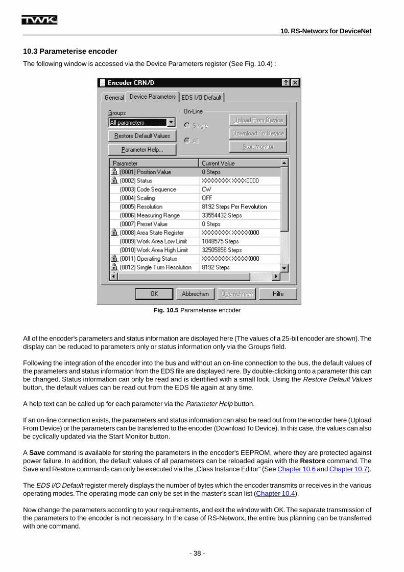
10.3 Parameterise encoder
The following window is accessed via the Device Parameters register (See Fig. 10.4) :
All of the encoder’s parameters and status information are displayed here (The values of a 25-bit encoder are shown). Thedisplay can be reduced to parameters only or status information only via the Groups field.
Following the integration of the encoder into the bus and without an on-line connection to the bus, the default values ofthe parameters and status information from the EDS file are displayed here. By double-clicking onto a parameter this canbe changed. Status information can only be read and is identified with a small lock. Using the Restore Default Valuesbutton, the default values can be read out from the EDS file again at any time.
A help text can be called up for each parameter via the Parameter Help button.
If an on-line connection exists, the parameters and status information can also be read out from the encoder here (UploadFrom Device) or the parameters can be transferred to the encoder (Download To Device). In this case, the values can alsobe cyclically updated via the Start Monitor button.
A Save command is available for storing the parameters in the encoder’s EEPROM, where they are protected againstpower failure. In addition, the default values of all parameters can be reloaded again with the Restore command. TheSave and Restore commands can only be executed via the „Class Instance Editor“ (See Chapter 10.6 and Chapter 10.7).
The EDS I/O Default register merely displays the number of bytes which the encoder transmits or receives in the variousoperating modes. The operating mode can only be set in the master’s scan list (Chapter 10.4).
Now change the parameters according to your requirements, and exit the window with OK. The separate transmission ofthe parameters to the encoder is not necessary. In the case of RS-Networx, the entire bus planning can be transferredwith one command.
- 39 -
Fig. 10.6 Bus set-up with master
Fig. 10.7 Scan list
10. RS-Networx for DeviceNet
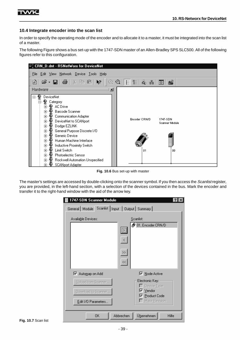
10.4 Integrate encoder into the scan list
In order to specify the operating mode of the encoder and to allocate it to a master, it must be integrated into the scan listof a master.
The following Figure shows a bus set-up with the 1747-SDN master of an Allen-Bradley SPS SLC500. All of the followingfigures refer to this configuration.
The master’s settings are accessed by double-clicking onto the scanner symbol. If you then access the Scanlist register,you are provided, in the left-hand section, with a selection of the devices contained in the bus. Mark the encoder andtransfer it to the right-hand window with the aid of the arrow key.
- 40 -
Fig. 10.8 Specify encoder operating mode
Fig. 10.9 Mapping
10. RS-Networx for DeviceNet
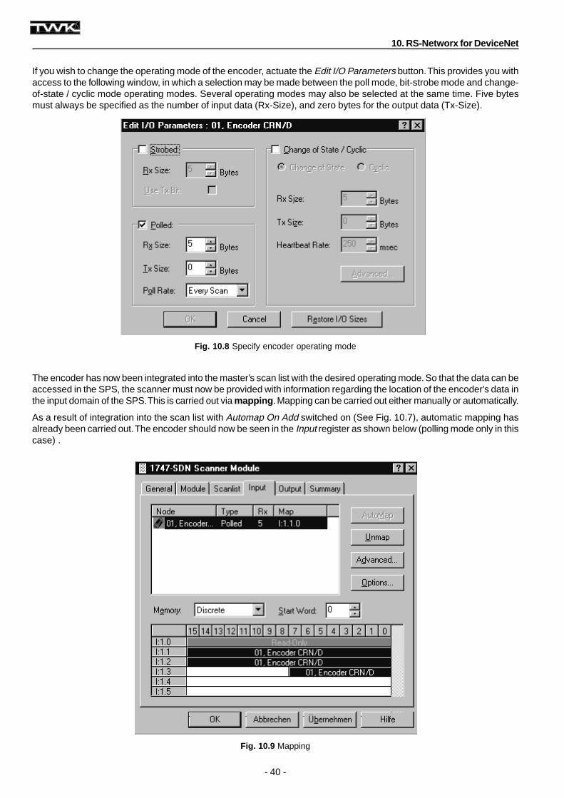
If you wish to change the operating mode of the encoder, actuate the Edit I/O Parameters button. This provides you withaccess to the following window, in which a selection may be made between the poll mode, bit-strobe mode and change-of-state / cyclic mode operating modes. Several operating modes may also be selected at the same time. Five bytesmust always be specified as the number of input data (Rx-Size), and zero bytes for the output data (Tx-Size).
The encoder has now been integrated into the master’s scan list with the desired operating mode. So that the data can beaccessed in the SPS, the scanner must now be provided with information regarding the location of the encoder’s data inthe input domain of the SPS. This is carried out via mapping . Mapping can be carried out either manually or automatically.
As a result of integration into the scan list with Automap On Add switched on (See Fig. 10.7), automatic mapping hasalready been carried out. The encoder should now be seen in the Input register as shown below (polling mode only in thiscase) .
- 41 -
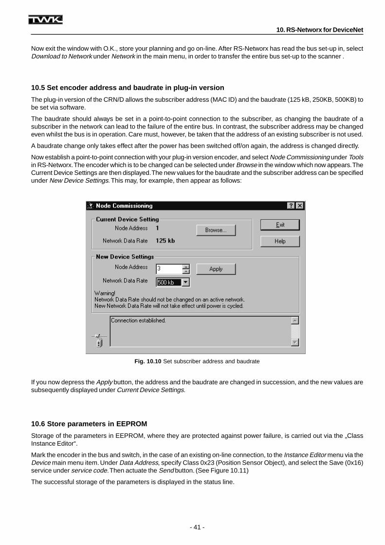
Fig. 10.10 Set subscriber address and baudrate
10. RS-Networx for DeviceNet
Now exit the window with O.K., store your planning and go on-line. After RS-Networx has read the bus set-up in, selectDownload to Network under Network in the main menu, in order to transfer the entire bus set-up to the scanner .
10.5 Set encoder address and baudrate in plug-in version
The plug-in version of the CRN/D allows the subscriber address (MAC ID) and the baudrate (125 kB, 250KB, 500KB) tobe set via software.
The baudrate should always be set in a point-to-point connection to the subscriber, as changing the baudrate of asubscriber in the network can lead to the failure of the entire bus. In contrast, the subscriber address may be changedeven whilst the bus is in operation. Care must, however, be taken that the address of an existing subscriber is not used.
A baudrate change only takes effect after the power has been switched off/on again, the address is changed directly.
Now establish a point-to-point connection with your plug-in version encoder, and select Node Commissioning under Toolsin RS-Networx. The encoder which is to be changed can be selected under Browse in the window which now appears. TheCurrent Device Settings are then displayed. The new values for the baudrate and the subscriber address can be specifiedunder New Device Settings. This may, for example, then appear as follows:
If you now depress the Apply button, the address and the baudrate are changed in succession, and the new values aresubsequently displayed under Current Device Settings.
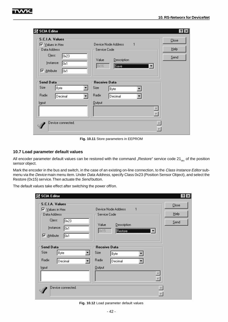
10.6 Store parameters in EEPROM
Storage of the parameters in EEPROM, where they are protected against power failure, is carried out via the „ClassInstance Editor“.
Mark the encoder in the bus and switch, in the case of an existing on-line connection, to the Instance Editor menu via theDevice main menu item. Under Data Address, specify Class 0x23 (Position Sensor Object), and select the Save (0x16)service under service code. Then actuate the Send button. (See Figure 10.11)
The successful storage of the parameters is displayed in the status line.
- 42 -
Fig. 10.11 Store parameters in EEPROM
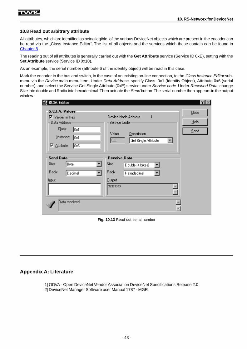
Fig. 10.12 Load parameter default values
10. RS-Networx for DeviceNet
10.7 Load parameter default values
All encoder parameter default values can be restored with the command „Restore“ service code 21dec
of the positionsensor object.
Mark the encoder in the bus and switch, in the case of an existing on-line connection, to the Class Instance Editor sub-menu via the Device main menu item. Under Data Address, specify Class 0x23 (Position Sensor Object), and select theRestore (0x15) service. Then actuate the Send button.
The default values take effect after switching the power off/on.
- 43 -
Fig. 10.13 Read out serial number
Appendix A: Literature
|1| ODVA - Open DeviceNet Vendor Association DeviceNet Specifications Release 2.0|2| DeviceNet Manager Software user Manual 1787 - MGR
10. RS-Networx for DeviceNet
10.8 Read out arbitrary attribute
All attributes, which are identified as being legible, of the various DeviceNet objects which are present in the encoder canbe read via the „Class Instance Editor“. The list of all objects and the services which these contain can be found inChapter 8 .
The reading out of all attributes is generally carried out with the Get Attribute service (Service ID 0xE), setting with theSet Attribute service (Service ID 0x10).
As an example, the serial number (attribute 6 of the identity object) will be read in this case.
Mark the encoder in the bus and switch, in the case of an existing on-line connection, to the Class Instance Editor sub-menu via the Device main menu item. Under Data Address, specify Class 0x1 (Identity Object), Attribute 0x6 (serialnumber), and select the Service Get Single Attribute (0xE) service under Service code. Under Received Data, changeSize into double and Radix into hexadecimal. Then actuate the Send button. The serial number then appears in the outputwindow.


![· 26 fd.n. 63 27 in. 63 29 63 30 ffn. 63 30 in. 63 30 ffn. 63 31 fJ.n. 63 01 111.8. 63 02 63 04 gxJ.tJ. 63 63 08 63 08 63 10 111.8. 63 11 63 08 63 19 f].n. 63 25 fin. 63 25 ffn](https://img.pdfslide.us/doc/110x75/60108244c72a76533f3ba5ab/26-fdn-63-27-in-63-29-63-30-ffn-63-30-in-63-30-ffn-63-31-fjn-63-01-1118.jpg)