Embed Size (px)
Citation preview
Hemostasis System
User manual
115191-US(AE)June 2019
2 Publication Information
Publication Information
Copyright notice
© 2015–2017, 2019 Haemonetics Corporation
The contents of this manual are the property of Haemonetics Corporation.
Any information or descriptions contained in this manual may not be reproduced and released to any of the general public, or used in conjunction with any professional instructions without written consent of Haemonetics Corporation, USA.
Confidential/proprietary notices
Use of any portion(s) of this document to copy, translate, disassemble or decompile, or create or attempt to create by reverse engineering (or otherwise) the source code from the object code of Haemonetics products is expressly prohibited.
This product contains mbedTLS, which is licensed under the Apache License, Version 2.0 (the "License"). You may not use that file except in compliance with the License. You may obtain a copy of the License at:
http://www.apache.org/licenses/LICENSE-2.0
Unless required by applicable law or agreed to in writing, software distributed under the License is distributed on an "AS IS" BASIS, WITHOUT WARRANTIES OR CONDITIONS OF ANY KIND, either express or implied. See the License for the specific language governing permissions and limitations under the License.
Disclaimer This manual is intended as a guide to provide the user with necessary instructions on the proper use and maintenance of certain Haemonetics Corporation products. This manual should be used in conjunction with instruction and training supplied by qualified Haemonetics personnel.
Any failure to follow the instructions as described, including use of materials or products not provided or recommended by Haemonetics, could result in impaired product function, injury to the user or others, or void applicable product warranties. Haemonetics accepts no responsibility for liability resulting from improper use or maintenance of its products.
Utilization of Haemonetics products may require the user to handle and dispose of blood-contaminated material. Users must fully understand and implement all regulations governing the safe handling of blood products and waste, including the policies and procedures of their facility.
Handling and use of any blood products collected or stored using Haemonetics equipment are subject to the decisions of the attending physician or other qualified medical personnel. Haemonetics makes no warranty with respect to such blood products.
P/N 115191-US, Manual revision: AE Haemonetics® TEG® 6s User Manual
Publication Information 3
Patient diagnosis is the sole responsibility of the attending physician or other qualified medical personnel.
The screenshots appearing in this manual are provided for illustrative purposes only, and may differ from the actual software screens. All organization, donor/patient, and user names in this manual are fictitious. Any similarity to the name of an organization or person is unintentional.
The TEG 6s analyzer is licensed for sale or use only in in-patient hospitals and laboratories that are primary providers to such hospitals.
Document updates
The document is furnished for information use only, is subject to change without notice and should not be construed as a commitment by Haemonetics Corporation. Haemonetics Corporation assumes no responsibility or liability for any errors or inaccuracies that may appear in the informational content contained in this material. For the purpose of clarity, Haemonetics Corporation considers only the most recent version of this document to be valid.
Trademarks and patents
Haemonetics, TEG, RapidTEG, Thrombelastograph, TEG Manager and 1-800-GET-A-TEG are trademarks or registered trademarks of Haemonetics
Corporation in the US, other countries, or both. PlateletMapping is a registered trademark of Cora Healthcare, Inc. Vacutainer is a registered trademark of Becton, Dickinson & Company.
US patent numbers 7,261,861, 7,879,615, 8,236,568, 6,787,363, 7,179,652, 7,732,213, and 9,068,966.
Reader comments
Any comments or suggestions regarding this publication are welcomed and should be forwarded to the attention of:
Corporate headquarters International headquartersHaemonetics Corporation Haemonetics S.A.400 Wood Road Signy CentreBraintree, MA 02184 Rue des Fléchères 6U.S.A. P.O. Box 262Tel.: +1 781 848 7100 1274 Signy-Centre, SwitzerlandFax: +1 781 848 5106 Tel.: +41 22 363 9011
Fax: +41 22 363 9054
Rx Only Caution: USA Federal Law restricts the sale, distribution, or use of this device to, by, or on the order of a licensed healthcare practitioner.
Note: Availability of devices may vary from one country or region to another as a result of specific local regulatory approval or clearance requirements. Applicable laws may restrict the sale, distribution, or use of this device to, by, or on the order of a licensed healthcare practitioner.
Haemonetics® TEG® 6s User Manual P/N 115191-US, Manual revision: AE

4 Publication Information
Haemonetics worldwide
Please direct any written inquiries to the appropriate address. For a list of worldwide office locations and contact information, visit www.haemonetics.com/officelocations
P/N 115191-US, Manual revision: AE Haemonetics® TEG® 6s User Manual
Table of Contents
Chapter 1, Introduction
Overview . . . . . . . . . . . . . . . . . . . . . . . . . . . . . . . . . . . . . . . . . . . . . . . . . . . 10Purpose of the manual . . . . . . . . . . . . . . . . . . . . . . . . . . . . . . . . . . . . . . 10What is the TEG 6s System? . . . . . . . . . . . . . . . . . . . . . . . . . . . . . . . . . 10Intended use . . . . . . . . . . . . . . . . . . . . . . . . . . . . . . . . . . . . . . . . . . . . . . 11Essential performance . . . . . . . . . . . . . . . . . . . . . . . . . . . . . . . . . . . . . . 12Precautions . . . . . . . . . . . . . . . . . . . . . . . . . . . . . . . . . . . . . . . . . . . . . . . 12Cybersecurity . . . . . . . . . . . . . . . . . . . . . . . . . . . . . . . . . . . . . . . . . . . . . 13
Customer Service. . . . . . . . . . . . . . . . . . . . . . . . . . . . . . . . . . . . . . . . . . . . . 14Clinical training . . . . . . . . . . . . . . . . . . . . . . . . . . . . . . . . . . . . . . . . . . . . 14Repair service . . . . . . . . . . . . . . . . . . . . . . . . . . . . . . . . . . . . . . . . . . . . . 14Preventive maintenance . . . . . . . . . . . . . . . . . . . . . . . . . . . . . . . . . . . . . 14Product return guidelines . . . . . . . . . . . . . . . . . . . . . . . . . . . . . . . . . . . . 14
Symbols . . . . . . . . . . . . . . . . . . . . . . . . . . . . . . . . . . . . . . . . . . . . . . . . . . . . 15Symbols found in this document . . . . . . . . . . . . . . . . . . . . . . . . . . . . . . . 15Symbols found on the analyzer and packaging . . . . . . . . . . . . . . . . . . . 15
Chapter 2, TEG® Analyzer Description
TEG Analyzer Description Overview . . . . . . . . . . . . . . . . . . . . . . . . . . . . . . 20Exterior Front Components . . . . . . . . . . . . . . . . . . . . . . . . . . . . . . . . . . . . . 21
LCD touch screen . . . . . . . . . . . . . . . . . . . . . . . . . . . . . . . . . . . . . . . . . . 21Cartridge slot. . . . . . . . . . . . . . . . . . . . . . . . . . . . . . . . . . . . . . . . . . . . . . 21
Exterior Back Components . . . . . . . . . . . . . . . . . . . . . . . . . . . . . . . . . . . . . 22Carrying handle. . . . . . . . . . . . . . . . . . . . . . . . . . . . . . . . . . . . . . . . . . . . 22Cooling fan . . . . . . . . . . . . . . . . . . . . . . . . . . . . . . . . . . . . . . . . . . . . . . . 22USB ports . . . . . . . . . . . . . . . . . . . . . . . . . . . . . . . . . . . . . . . . . . . . . . . . 22Ethernet port . . . . . . . . . . . . . . . . . . . . . . . . . . . . . . . . . . . . . . . . . . . . . . 23Fuse holder . . . . . . . . . . . . . . . . . . . . . . . . . . . . . . . . . . . . . . . . . . . . . . . 23Fuse . . . . . . . . . . . . . . . . . . . . . . . . . . . . . . . . . . . . . . . . . . . . . . . . . . . . 23Power jack. . . . . . . . . . . . . . . . . . . . . . . . . . . . . . . . . . . . . . . . . . . . . . . . 23On/Off Switch . . . . . . . . . . . . . . . . . . . . . . . . . . . . . . . . . . . . . . . . . . . . . 23
Disposable Assay Cartridges . . . . . . . . . . . . . . . . . . . . . . . . . . . . . . . . . . . . 24Sample port. . . . . . . . . . . . . . . . . . . . . . . . . . . . . . . . . . . . . . . . . . . . . . . 24Barcode. . . . . . . . . . . . . . . . . . . . . . . . . . . . . . . . . . . . . . . . . . . . . . . . . . 24
Chapter 3, Safety and Precautions
Storage and Handling . . . . . . . . . . . . . . . . . . . . . . . . . . . . . . . . . . . . . . . . . 26Storing and handling the analyzer. . . . . . . . . . . . . . . . . . . . . . . . . . . . . . 26Storing and handling the cartridges . . . . . . . . . . . . . . . . . . . . . . . . . . . . 27Transporting the analyzer . . . . . . . . . . . . . . . . . . . . . . . . . . . . . . . . . . . . 27
Haemonetics® TEG® 6s User Manual P/N 115191-US, Manual revision: AE
6 Table of Contents
Warnings for the Operator . . . . . . . . . . . . . . . . . . . . . . . . . . . . . . . . . . . . . .28Electrical shock hazards . . . . . . . . . . . . . . . . . . . . . . . . . . . . . . . . . . . . .28Power outlet connection . . . . . . . . . . . . . . . . . . . . . . . . . . . . . . . . . . . . .28Bloodborne pathogens . . . . . . . . . . . . . . . . . . . . . . . . . . . . . . . . . . . . . .28Handling of glass objects. . . . . . . . . . . . . . . . . . . . . . . . . . . . . . . . . . . . .29
Chapter 4, Getting Started
Overview. . . . . . . . . . . . . . . . . . . . . . . . . . . . . . . . . . . . . . . . . . . . . . . . . . . .32TEG Analyzer Design . . . . . . . . . . . . . . . . . . . . . . . . . . . . . . . . . . . . . . . . . .33
Principles of design . . . . . . . . . . . . . . . . . . . . . . . . . . . . . . . . . . . . . . . . .33TEG Analyzer Parameters . . . . . . . . . . . . . . . . . . . . . . . . . . . . . . . . . . . . . .34TEG Analyzer Tests . . . . . . . . . . . . . . . . . . . . . . . . . . . . . . . . . . . . . . . . . . .35Setting Up and Logging into the Analyzer . . . . . . . . . . . . . . . . . . . . . . . . . .36
Set up the analyzer . . . . . . . . . . . . . . . . . . . . . . . . . . . . . . . . . . . . . . . . .36Start the analyzer . . . . . . . . . . . . . . . . . . . . . . . . . . . . . . . . . . . . . . . . . .37Log into the analyzer . . . . . . . . . . . . . . . . . . . . . . . . . . . . . . . . . . . . . . . .37Update your password. . . . . . . . . . . . . . . . . . . . . . . . . . . . . . . . . . . . . . .38Log out of the analyzer . . . . . . . . . . . . . . . . . . . . . . . . . . . . . . . . . . . . . .39Turn off the analyzer . . . . . . . . . . . . . . . . . . . . . . . . . . . . . . . . . . . . . . . .39
Exploring the Touchscreen . . . . . . . . . . . . . . . . . . . . . . . . . . . . . . . . . . . . . .40Home screen . . . . . . . . . . . . . . . . . . . . . . . . . . . . . . . . . . . . . . . . . . . . . .40Icons . . . . . . . . . . . . . . . . . . . . . . . . . . . . . . . . . . . . . . . . . . . . . . . . . . . .41
Viewing Test Results. . . . . . . . . . . . . . . . . . . . . . . . . . . . . . . . . . . . . . . . . . .42Test results screen. . . . . . . . . . . . . . . . . . . . . . . . . . . . . . . . . . . . . . . . . .42Tracing screens . . . . . . . . . . . . . . . . . . . . . . . . . . . . . . . . . . . . . . . . . . . .43
Configuring Settings . . . . . . . . . . . . . . . . . . . . . . . . . . . . . . . . . . . . . . . . . . .45Configure date and time settings. . . . . . . . . . . . . . . . . . . . . . . . . . . . . . .45Change the time zone . . . . . . . . . . . . . . . . . . . . . . . . . . . . . . . . . . . . . . .46Configure LAN settings . . . . . . . . . . . . . . . . . . . . . . . . . . . . . . . . . . . . . .48Calibrate the touchscreen . . . . . . . . . . . . . . . . . . . . . . . . . . . . . . . . . . . .50View information about the analyzer . . . . . . . . . . . . . . . . . . . . . . . . . . . .50
Chapter 5, Operating the TEG® Analyzer
Operation Overview . . . . . . . . . . . . . . . . . . . . . . . . . . . . . . . . . . . . . . . . . . .54Disposable assay cartridges . . . . . . . . . . . . . . . . . . . . . . . . . . . . . . . . . .54Blood samples. . . . . . . . . . . . . . . . . . . . . . . . . . . . . . . . . . . . . . . . . . . . .54
Running a Patient Test . . . . . . . . . . . . . . . . . . . . . . . . . . . . . . . . . . . . . . . . .56Quick guide for running a patient test . . . . . . . . . . . . . . . . . . . . . . . . . . .56Detailed guide for running a patient test . . . . . . . . . . . . . . . . . . . . . . . . .56
Stopping a Test . . . . . . . . . . . . . . . . . . . . . . . . . . . . . . . . . . . . . . . . . . . . . . .64Viewing Stored Patient Data. . . . . . . . . . . . . . . . . . . . . . . . . . . . . . . . . . . . .66
Quick guide for viewing stored patient data. . . . . . . . . . . . . . . . . . . . . . .66Detailed guide for viewing stored patient data. . . . . . . . . . . . . . . . . . . . .66
P/N 115191-US, Manual revision: AE Haemonetics® TEG® 6s User Manual
Table of Contents 7
Chapter 6, Quality Control
Overview. . . . . . . . . . . . . . . . . . . . . . . . . . . . . . . . . . . . . . . . . . . . . . . . . . . .70IQCP . . . . . . . . . . . . . . . . . . . . . . . . . . . . . . . . . . . . . . . . . . . . . . . . . . . .70Analyzer Quality Control (internal QC) . . . . . . . . . . . . . . . . . . . . . . . . . .70Reagent Quality Control (external QC) . . . . . . . . . . . . . . . . . . . . . . . . . .71
Performing Citrated Reagent QC . . . . . . . . . . . . . . . . . . . . . . . . . . . . . . . . .72Citrated controls . . . . . . . . . . . . . . . . . . . . . . . . . . . . . . . . . . . . . . . . . . .72General procedure: run QC in a patient assay cartridge . . . . . . . . . . . . .72Run normal blood in a Citrated Multichannel or Citrated: K, RT, FF assay cartridge. . . . . . . . . . . . . . . . . . . . . . . . . . . . . . . . . . . . . . . . . . . . . . . . . .76Run Abnormal QC in a Citrated Multichannel cartridge. . . . . . . . . . . . . .77Run Abnormal QC and Lysis QC in a Citrated: K, RT, FF cartridge . . . .78
Performing PlateletMapping® Reagent QC . . . . . . . . . . . . . . . . . . . . . . . . .80PlateletMapping controls . . . . . . . . . . . . . . . . . . . . . . . . . . . . . . . . . . . . .80Run a QC blood sample in a PlateletMapping cartridge . . . . . . . . . . . . .80
Viewing Stored QC Data . . . . . . . . . . . . . . . . . . . . . . . . . . . . . . . . . . . . . . .82Quick guide for viewing stored QC data . . . . . . . . . . . . . . . . . . . . . . . . .82Detailed guide for viewing stored QC data . . . . . . . . . . . . . . . . . . . . . . .82
Chapter 7, Troubleshooting and Maintenance
Errors and Alerts. . . . . . . . . . . . . . . . . . . . . . . . . . . . . . . . . . . . . . . . . . . . . .86Error messages . . . . . . . . . . . . . . . . . . . . . . . . . . . . . . . . . . . . . . . . . . . .86Warning messages . . . . . . . . . . . . . . . . . . . . . . . . . . . . . . . . . . . . . . . . .87Critical alert messages . . . . . . . . . . . . . . . . . . . . . . . . . . . . . . . . . . . . . .87Error message table . . . . . . . . . . . . . . . . . . . . . . . . . . . . . . . . . . . . . . . .88
Cleaning and Disinfecting the Analyzer . . . . . . . . . . . . . . . . . . . . . . . . . . . .94Materials needed. . . . . . . . . . . . . . . . . . . . . . . . . . . . . . . . . . . . . . . . . . .94Clean the analyzer. . . . . . . . . . . . . . . . . . . . . . . . . . . . . . . . . . . . . . . . . .94Clean the filter . . . . . . . . . . . . . . . . . . . . . . . . . . . . . . . . . . . . . . . . . . . . .95
Chapter 8, Specifications and Performance Characteristics
Specifications . . . . . . . . . . . . . . . . . . . . . . . . . . . . . . . . . . . . . . . . . . . . . . . .98Physical specifications. . . . . . . . . . . . . . . . . . . . . . . . . . . . . . . . . . . . . . .98Environmental specifications . . . . . . . . . . . . . . . . . . . . . . . . . . . . . . . . . .98Electrical specifications . . . . . . . . . . . . . . . . . . . . . . . . . . . . . . . . . . . . . .98Printer specification . . . . . . . . . . . . . . . . . . . . . . . . . . . . . . . . . . . . . . . . .99Analytical Measurement Ranges. . . . . . . . . . . . . . . . . . . . . . . . . . . . . . .99
Performance Characteristics . . . . . . . . . . . . . . . . . . . . . . . . . . . . . . . . . . .101FCC Compliance . . . . . . . . . . . . . . . . . . . . . . . . . . . . . . . . . . . . . . . . . .101Warranty . . . . . . . . . . . . . . . . . . . . . . . . . . . . . . . . . . . . . . . . . . . . . . . .101
Haemonetics® TEG® 6s User Manual P/N 115191-US, Manual revision: AE
8 Table of Contents
Appendix A, IEC/EN 60601-1-2 Standard Requirements
Operation Precautions . . . . . . . . . . . . . . . . . . . . . . . . . . . . . . . . . . . . . . . .104Power supply . . . . . . . . . . . . . . . . . . . . . . . . . . . . . . . . . . . . . . . . . . . . .104Electro-magnetic immunity . . . . . . . . . . . . . . . . . . . . . . . . . . . . . . . . . .104
Electromagnetic Compatibility . . . . . . . . . . . . . . . . . . . . . . . . . . . . . . . . . .105
P/N 115191-US, Manual revision: AE Haemonetics® TEG® 6s User Manual
Chapter 1
Introduction
Overview. . . . . . . . . . . . . . . . . . . . . . . . . . . . . . . . . . . . . . . . . . . . . . . . . . . .10Purpose of the manual . . . . . . . . . . . . . . . . . . . . . . . . . . . . . . . . . . . . . .10What is the TEG 6s System? . . . . . . . . . . . . . . . . . . . . . . . . . . . . . . . . .10Intended use . . . . . . . . . . . . . . . . . . . . . . . . . . . . . . . . . . . . . . . . . . . . . . 11Essential performance. . . . . . . . . . . . . . . . . . . . . . . . . . . . . . . . . . . . . . .12Precautions . . . . . . . . . . . . . . . . . . . . . . . . . . . . . . . . . . . . . . . . . . . . . . .12Cybersecurity. . . . . . . . . . . . . . . . . . . . . . . . . . . . . . . . . . . . . . . . . . . . . .13
Customer Service . . . . . . . . . . . . . . . . . . . . . . . . . . . . . . . . . . . . . . . . . . . . .14Clinical training . . . . . . . . . . . . . . . . . . . . . . . . . . . . . . . . . . . . . . . . . . . .14Repair service . . . . . . . . . . . . . . . . . . . . . . . . . . . . . . . . . . . . . . . . . . . . .14Preventive maintenance . . . . . . . . . . . . . . . . . . . . . . . . . . . . . . . . . . . . .14Product return guidelines. . . . . . . . . . . . . . . . . . . . . . . . . . . . . . . . . . . . .14
Symbols . . . . . . . . . . . . . . . . . . . . . . . . . . . . . . . . . . . . . . . . . . . . . . . . . . . .15Symbols found in this document . . . . . . . . . . . . . . . . . . . . . . . . . . . . . . .15Symbols found on the analyzer and packaging. . . . . . . . . . . . . . . . . . . .15
Haemonetics® TEG® 6s User Manual P/N 115191-US, Manual revision: AE
10 Chapter 1, Introduction
Overview
Purpose of the manual
The TEG® 6s User Manual provides users with the information needed to
effectively operate the TEG® 6s Hemostasis analyzer. This manual includes:
A detailed description of the analyzer.
Instructions for operating the analyzer and troubleshooting any difficulties.
Information on how to properly handle and maintain the analyzer.
Specifications and performance capabilities.
Use this manual in combination with training supplied by qualified Haemonetics personnel.
What is the TEG 6s System?
The TEG® 6s Hemostasis System consists of the following components:
TEG 6s Hemostasis Analyzer
Disposable assay cartridges with preloaded dried reagents
Service-Maintenance-Settings (SMS) software interface
TEG Manager ® software interface
The TEG 6s analyzer monitors the harmonic motion of a pendant drop of blood in response to external vibration. As the sample transitions from a liquid state to a gel-like state during clotting, the modulus of elasticity and resonant frequency increase. The analyzer measures these variations in resonant frequency during clotting and lysis and displays the results on a touchscreen display.
Disposable cartridges are used for processing whole blood samples. Blood is delivered by transfer pipette to a small port in the cartridge. Once a sample has been added to the cartridge and testing has begun, the sample is inaccessible to the user. The cartridges contain all necessary reagents for performing an assay.
The TEG analyzer has two modes of operation: (1) Stand-alone, and (2) computer-controlled through the network interface. Service-Maintenance-Settings (SMS) software provides the interface for an administrator or qualified service technician to change configuration settings, update, backup, and restore firmware and data files, and manage analyzer calibration parameters. For more information about the SMS software, consult the TEG 6s Site Administrator Guide.
TEG Manager is an accessory application that provides remote viewing of TEG analyzer test results and administration of all connected analyzers. TEG Manager interfaces with analyzers to obtain clinical data and retrieves patient information from an external Hospital Information System (HIS). For more
information about TEG Manager, consult the TEG Manager® User and Site Administrator Guide.
P/N 115191-US, Manual revision: AE Haemonetics® TEG® 6s User Manual
Chapter 1, Introduction 11
Intended use The TEG® 6s Hemostasis System consists of the TEG 6s Hemostasis Analyzer, TEG 6s PlateletMapping Assay Cartridge, TEG 6s Citrated Multichannel Cartridge, and TEG 6s Citrated: K, RT, FF Assay Cartridge. The TEG 6s Hemostasis System is intended for in vitro diagnostic use to provide qualitative assessment of platelet function and semi-quantitative indications of the hemostasis state of a venous blood sample. The TEG 6s Hemostasis System records the kinetic changes in a sample of heparinized or 3.2% citrated whole blood as the sample clots.
The PlateletMapping Assay Cartridge provides four channels of dried-in-place reagents, HKH (Kaolin with Heparinase), Activator F, AA, and ADP (one reagent in each channel). In combination, MA parameter results from these four reagents are used to calculate the parameters platelet % Inhibition and % Aggregation for AA and ADP. A PlateletMapping ADP Assay Cartridge is available without the AA reagent.
The Citrated Multichannel Cartridge contains four independent assays (CK, CRT, CKH and CFF) and the system output consists of a table of numerical values for parameters R, K, Angle, MA, and FLEV.
The Citrated: K, RT, FF Assay Cartridge contains three independent assays (CK, CRT and CFF) and the system output consists of a table of numerical values for parameters R, LY30, and MA.
The CK assay monitors the hemostasis process via the intrinsic pathway in 3.2% citrated whole blood specimens on the TEG 6s Hemostasis System. Clotting characteristics are described by the functional parameters R (clotting time) and LY30 (fibrinolysis after 30 minutes of reaching maximum clot strength).
The CRT assay monitors the hemostasis process via both the intrinsic and extrinsic pathways in 3.2% citrated whole blood specimens on the TEG 6s Hemostasis System. Clotting characteristics are described by the functional parameter MA (maximum clot strength).
The CKH assay monitors the effects of heparin in 3.2% citrated whole blood specimens on the TEG 6s System. CKH is used in conjunction with CK, and heparin influence is determined by comparing clotting times (R) between the two tests.
The CFF assay monitors hemostasis of 3.2% citrated whole blood specimens in the TEG 6s Hemostasis System after blocking platelet contributions to clot strength. Clotting characteristics are described by the functional parameter MA (maximum clot strength).
Results from the TEG 6s analysis should not be the sole basis for a patient diagnosis, but should be evaluated together with the patient’s medical history, the clinical picture and, if necessary, further hemostasis tests. The indication for TEG 6s Hemostasis System use is with adult patients (18 years and older) where an evaluation of their blood hemostasis properties is desired. Hemostasis evaluation with the TEG 6s Hemostasis System using the PlateletMapping Assay Cartridge and Citrated Multichannel Cartridge is used
Haemonetics® TEG® 6s User Manual P/N 115191-US, Manual revision: AE
12 Chapter 1, Introduction
to assess clinical conditions in cardiovascular surgery and cardiology procedures to assess hemorrhage or thrombosis conditions. Hemostasis evaluation with the TEG 6s Hemostasis System using the Citrated: K, RT, FF Assay Cartridge is used to assess clinical conditions in a trauma setting to assess hemorrhage or thrombosis conditions.
For professional use only.
Essential performance
The TEG 6s Hemostasis System has the following characteristics identified as essential performance:
1. The device shall accurately measure changes in a blood sample during clotting and lysis.
2. The device shall indicate test results that are out of range.
3. The device shall display an error message and prevent completion of a test if any electromechanical or pneumatic function of the analyzer-cartridge combination is not operating satisfactorily.
Precautions The operator should be aware of the following precautions:
Read and understand the entire contents of this manual before operating the TEG analyzer - especially precautionary information and specifications.
Caution: Federal Law restricts this device to sale by or on the order of a licensed practitioner.
The TEG analyzer is to be operated by qualified personnel only.
If this equipment is used in a manner inconsistent with this manual, protections provided by the device may be impaired.
Use only Haemonetics parts and accessories with the TEG analyzer. Third-party accessories may cause improper performance.
DO NOT use malfunctioning equipment. Have the unit repaired by an authorized Haemonetics service representative.
DO NOT place anything other than human blood, plasma, or quality control materials into a cartridge.
Upon removal from the TEG analyzer, used cartridges must be immediately disposed of according to local standard operating procedures for the removal of biohazardous material and should not be mixed with non-biohazardous waste.
P/N 115191-US, Manual revision: AE Haemonetics® TEG® 6s User Manual
Chapter 1, Introduction 13
Cybersecurity Haemonetics recommends the following cybersecurity controls for the TEG 6s Hemostasis System:
The SMS software and TEG 6s analyzer should be installed behind a firewall and physically secured per your organization’s security guidelines.
User accounts should not be shared, and passwords should be kept confidential.
No Personally Identifiable Information (PII) or Protected Health information (PHI) should be entered in the analyzer’s Test Information field, as this field is not encrypted when stored locally.
TLS (Transport Layer Security) V1.2 should be enabled on the TEG Manager server.
SMS should be connected to the analyzer only on a secure Local Area Network (LAN).
Haemonetics® TEG® 6s User Manual P/N 115191-US, Manual revision: AE
14 Chapter 1, Introduction
Customer Service
Clinical training The local Haemonetics representative will provide staff training upon delivery of the TEG system equipment and should be contacted to organize further instruction, if needed.
Repair service Haemonetics maintains a worldwide network of company-trained service representatives responsible for responding to technical needs concerning equipment. If service beyond the routine maintenance and cleaning described in this manual is required, TEG System Technical Support should be contacted to provide specific instruction.
TEG System Technical Support is available 24 hours per day, 7 days per week
at 1-800-GET-A-TEG® (800-438-2834) or by e-mail at [email protected].
Preventive maintenance
General maintenance procedures should be performed as required. For instructions, refer to “Cleaning and Disinfecting the Analyzer” on page 7-94.
Preventive maintenance procedures should be conducted annually to ensure optimal mechanical functioning of the analyzer and are performed by a trained Haemonetics representative.
Product return guidelines
If, for any reason, merchandise must be returned to the company, the customer should contact TEG System Technical Support to arrange for repairs or returns using procedures to ensure proper handling and subsequent analysis. No returns will be accepted without advanced authorization.
Units returned to Haemonetics for repair are subject to biohazard charges if any component is contaminated with blood or blood products.
Alert: Haemonetics products must be properly cleaned and packaged prior to their return. It remains an important responsibility of the customer to reduce potential health hazards by being aware of the risks involved in the shipping, handling and testing of this material.
P/N 115191-US, Manual revision: AE Haemonetics® TEG® 6s User Manual
Chapter 1, Introduction 15
Symbols
Symbols found in this document
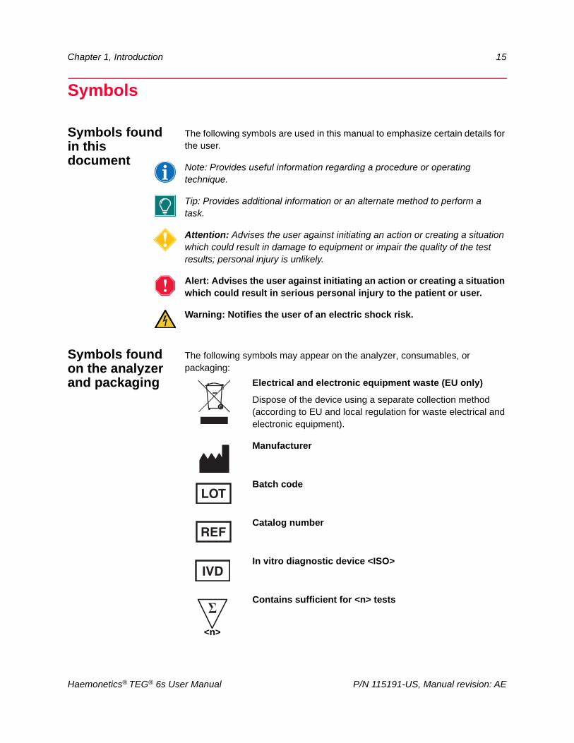
The following symbols are used in this manual to emphasize certain details for the user.
Note: Provides useful information regarding a procedure or operating technique.
Tip: Provides additional information or an alternate method to perform a task.
Attention: Advises the user against initiating an action or creating a situation which could result in damage to equipment or impair the quality of the test results; personal injury is unlikely.
Alert: Advises the user against initiating an action or creating a situation which could result in serious personal injury to the patient or user.
Warning: Notifies the user of an electric shock risk.
Symbols found on the analyzer and packaging
The following symbols may appear on the analyzer, consumables, or packaging:
Electrical and electronic equipment waste (EU only)
Dispose of the device using a separate collection method (according to EU and local regulation for waste electrical and electronic equipment).
Manufacturer
Batch code
Catalog number
In vitro diagnostic device <ISO>
Contains sufficient for <n> tests
<n>
Haemonetics® TEG® 6s User Manual P/N 115191-US, Manual revision: AE
16 Chapter 1, Introduction
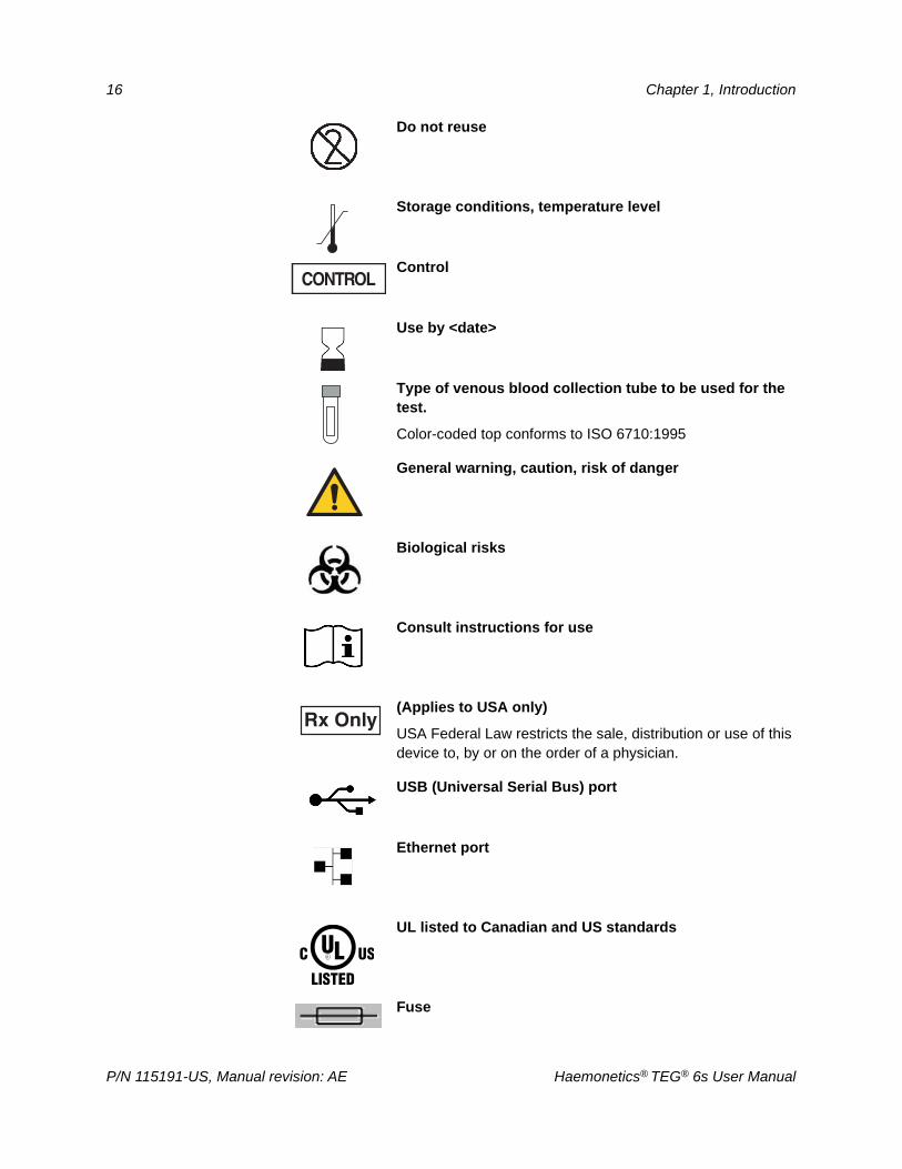
Do not reuse
Storage conditions, temperature level
Control
Use by <date>
Type of venous blood collection tube to be used for the test.
Color-coded top conforms to ISO 6710:1995
General warning, caution, risk of danger
Biological risks
Consult instructions for use
(Applies to USA only)
USA Federal Law restricts the sale, distribution or use of this device to, by or on the order of a physician.
USB (Universal Serial Bus) port
Ethernet port
UL listed to Canadian and US standards
Fuse
P/N 115191-US, Manual revision: AE Haemonetics® TEG® 6s User Manual
Chapter 1, Introduction 17
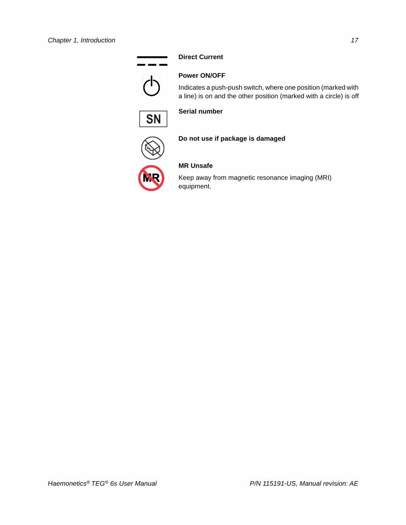
Direct Current
Power ON/OFF
Indicates a push-push switch, where one position (marked with a line) is on and the other position (marked with a circle) is off
Serial number
Do not use if package is damaged
MR Unsafe
Keep away from magnetic resonance imaging (MRI) equipment.
Haemonetics® TEG® 6s User Manual P/N 115191-US, Manual revision: AE


Chapter 2
TEG® Analyzer Description
TEG Analyzer Description Overview. . . . . . . . . . . . . . . . . . . . . . . . . . . . . . .20Exterior Front Components. . . . . . . . . . . . . . . . . . . . . . . . . . . . . . . . . . . . . .21
LCD touch screen . . . . . . . . . . . . . . . . . . . . . . . . . . . . . . . . . . . . . . . . . .21Cartridge slot . . . . . . . . . . . . . . . . . . . . . . . . . . . . . . . . . . . . . . . . . . . . . .21
Exterior Back Components . . . . . . . . . . . . . . . . . . . . . . . . . . . . . . . . . . . . . .22Carrying handle . . . . . . . . . . . . . . . . . . . . . . . . . . . . . . . . . . . . . . . . . . . .22Cooling fan . . . . . . . . . . . . . . . . . . . . . . . . . . . . . . . . . . . . . . . . . . . . . . .22USB ports . . . . . . . . . . . . . . . . . . . . . . . . . . . . . . . . . . . . . . . . . . . . . . . .22Ethernet port . . . . . . . . . . . . . . . . . . . . . . . . . . . . . . . . . . . . . . . . . . . . . .23Fuse holder . . . . . . . . . . . . . . . . . . . . . . . . . . . . . . . . . . . . . . . . . . . . . . .23Fuse. . . . . . . . . . . . . . . . . . . . . . . . . . . . . . . . . . . . . . . . . . . . . . . . . . . . .23Power jack . . . . . . . . . . . . . . . . . . . . . . . . . . . . . . . . . . . . . . . . . . . . . . . .23On/Off Switch . . . . . . . . . . . . . . . . . . . . . . . . . . . . . . . . . . . . . . . . . . . . .23
Disposable Assay Cartridges . . . . . . . . . . . . . . . . . . . . . . . . . . . . . . . . . . . .24Sample port . . . . . . . . . . . . . . . . . . . . . . . . . . . . . . . . . . . . . . . . . . . . . . .24Barcode . . . . . . . . . . . . . . . . . . . . . . . . . . . . . . . . . . . . . . . . . . . . . . . . . .24
Haemonetics® TEG® 6s User Manual P/N 115191-US, Manual revision: AE
20 Chapter 2, TEG® Analyzer Description
TEG Analyzer Description Overview
This chapter identifies the following main components of the TEG® 6s analyzer system and explains their intended functions.
Exterior front components
Exterior back components
Disposable assay cartridges
Note: Any references made to “front” or “back” are from the perspective of an operator facing the TEG analyzer.
The TEG 6s system consists of an analyzer and disposable assay cartridges. The analyzer contains a user-friendly interface in the form of a color touch-enabled display. Through this interface, the operator can control all operations of the analyzer except turning it on and off, which is accomplished by accessing a switch at the rear of the analyzer. The system is designed to accept a disposable plastic cartridge, into which a blood sample can be placed. Once a test is started, the analyzer processes the sample and reports the results on the touchscreen display.
P/N 115191-US, Manual revision: AE Haemonetics® TEG® 6s User Manual
Chapter 2, TEG® Analyzer Description 21
Exterior Front Components
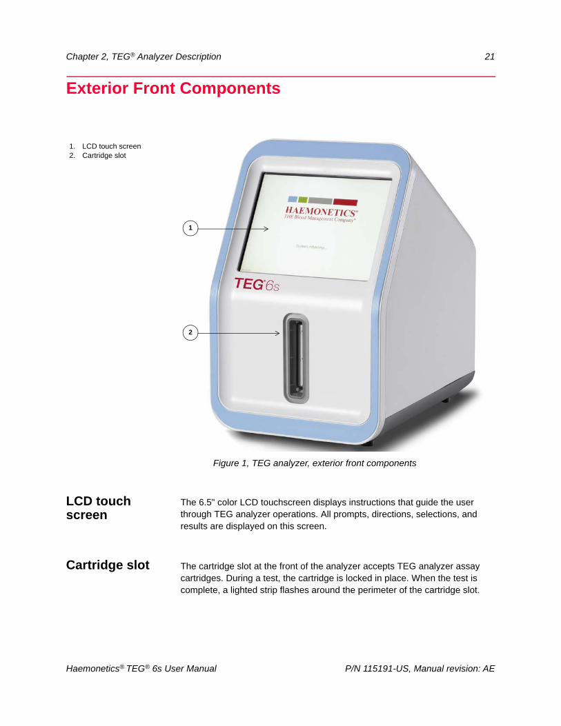
Figure 1, TEG analyzer, exterior front components
LCD touch screen
The 6.5" color LCD touchscreen displays instructions that guide the user through TEG analyzer operations. All prompts, directions, selections, and results are displayed on this screen.
Cartridge slot The cartridge slot at the front of the analyzer accepts TEG analyzer assay cartridges. During a test, the cartridge is locked in place. When the test is complete, a lighted strip flashes around the perimeter of the cartridge slot.
1. LCD touch screen2. Cartridge slot
1
2
Haemonetics® TEG® 6s User Manual P/N 115191-US, Manual revision: AE
22 Chapter 2, TEG® Analyzer Description
Exterior Back Components
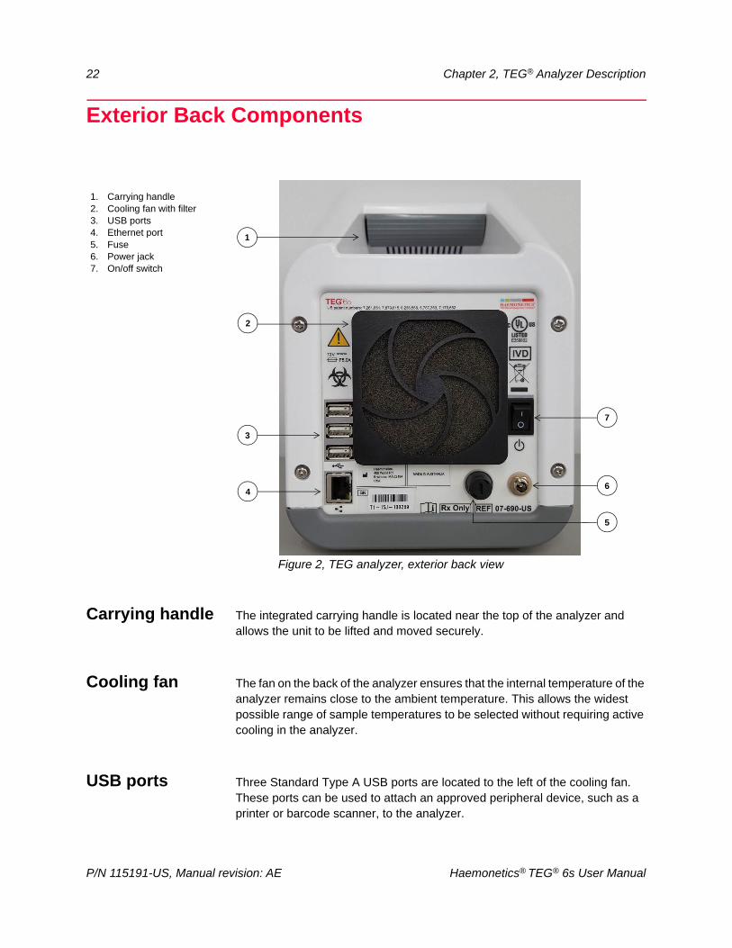
Figure 2, TEG analyzer, exterior back view
Carrying handle The integrated carrying handle is located near the top of the analyzer and allows the unit to be lifted and moved securely.
Cooling fan The fan on the back of the analyzer ensures that the internal temperature of the analyzer remains close to the ambient temperature. This allows the widest possible range of sample temperatures to be selected without requiring active cooling in the analyzer.
USB ports Three Standard Type A USB ports are located to the left of the cooling fan. These ports can be used to attach an approved peripheral device, such as a printer or barcode scanner, to the analyzer.
1. Carrying handle2. Cooling fan with filter3. USB ports4. Ethernet port5. Fuse6. Power jack7. On/off switch
3
1
2
4
5
7
6
P/N 115191-US, Manual revision: AE Haemonetics® TEG® 6s User Manual
Chapter 2, TEG® Analyzer Description 23
Attention: Do not connect non-approved devices (such as cellular phones, wireless dongles, etc.) to the USB ports, or use them to charge other equipment. Approved devices must comply with IEC/EN 60601-1 or IEC/EN 60950-1.
Ethernet port The analyzer may be connected via Ethernet cable to a stand-alone computer or Ethernet switch or router for service, maintenance and setup. LED lights on either side of the port have the following functions:
Fuse holder The fuse holder is a cylindrical housing that protects and holds the fuse.
Fuse The 250 Volt 5 Amp fuse is located inside the fuse holder on the back of the analyzer.
Power jack The power jack is located at the back of the analyzer and is the screw-on connection point for the power cord that is supplied by Haemonetics. Do not replace the cord with a substitute. If necessary, contact the local Haemonetics representative for a replacement. Always ensure that the power cord is connected to an appropriately grounded power source (100 - 240 volt 50/60 Hz) per your institution’s policy. Use an Uninterruptible Power Supply (UPS) unit between the analyzer and the power source.
Warning: Grounding reliability can be achieved only when the analyzer is connected to a properly grounded outlet.
On/Off Switch The power switch is located at the back of the analyzer. "I" indicates "on" and "O" indicates "off".
Left LED - Link Speed Right LED - Link Activity
Amber: operating in 1000 BT mode Blinking green: activity
Green: operating in 100 BT mode Off: no link established
Off: operating in 10 BT mode
Haemonetics® TEG® 6s User Manual P/N 115191-US, Manual revision: AE
24 Chapter 2, TEG® Analyzer Description
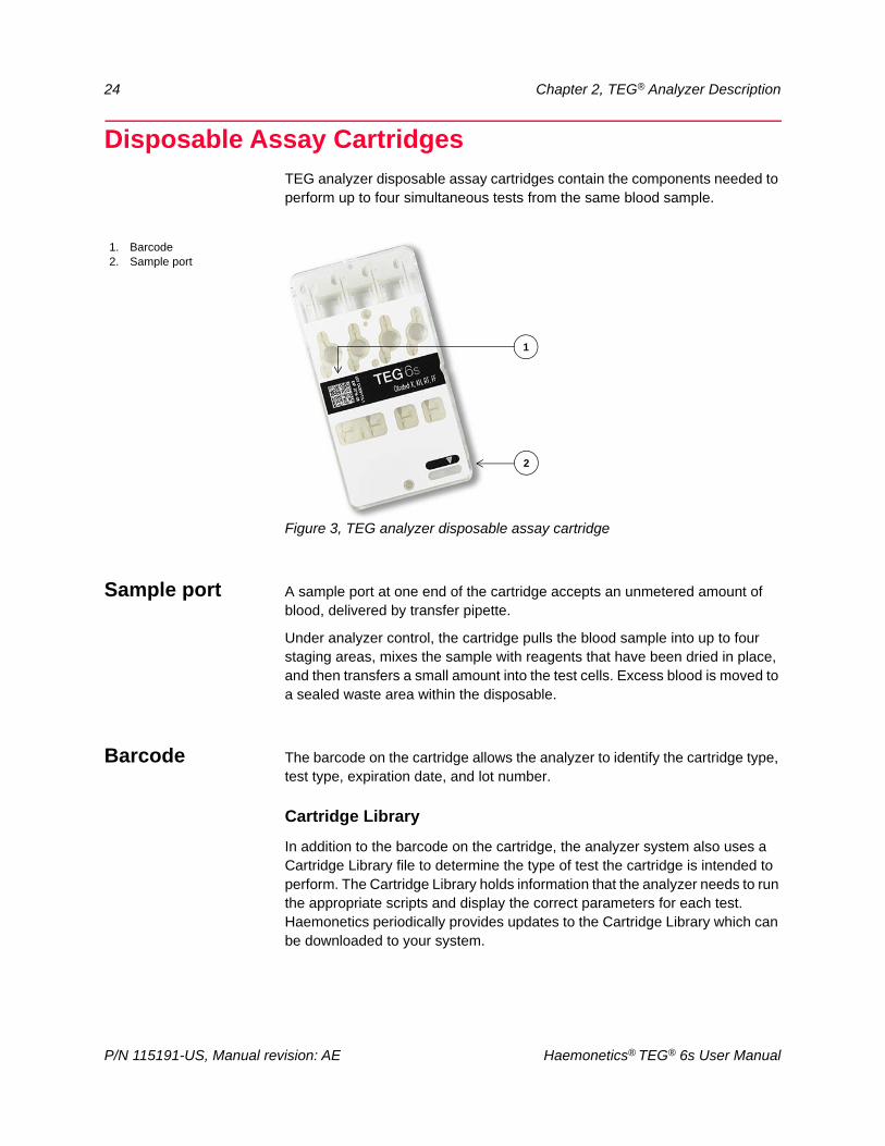
Disposable Assay CartridgesTEG analyzer disposable assay cartridges contain the components needed to perform up to four simultaneous tests from the same blood sample.
Figure 3, TEG analyzer disposable assay cartridge
Sample port A sample port at one end of the cartridge accepts an unmetered amount of blood, delivered by transfer pipette.
Under analyzer control, the cartridge pulls the blood sample into up to four staging areas, mixes the sample with reagents that have been dried in place, and then transfers a small amount into the test cells. Excess blood is moved to a sealed waste area within the disposable.
Barcode The barcode on the cartridge allows the analyzer to identify the cartridge type, test type, expiration date, and lot number.
Cartridge Library
In addition to the barcode on the cartridge, the analyzer system also uses a Cartridge Library file to determine the type of test the cartridge is intended to perform. The Cartridge Library holds information that the analyzer needs to run the appropriate scripts and display the correct parameters for each test. Haemonetics periodically provides updates to the Cartridge Library which can be downloaded to your system.
1. Barcode2. Sample port
1
2
P/N 115191-US, Manual revision: AE Haemonetics® TEG® 6s User Manual
Chapter 3
Safety and Precautions
Storage and Handling . . . . . . . . . . . . . . . . . . . . . . . . . . . . . . . . . . . . . . . . . .26Storing and handling the analyzer . . . . . . . . . . . . . . . . . . . . . . . . . . . . . .26Storing and handling the cartridges. . . . . . . . . . . . . . . . . . . . . . . . . . . . .27Transporting the analyzer . . . . . . . . . . . . . . . . . . . . . . . . . . . . . . . . . . . .27
Warnings for the Operator . . . . . . . . . . . . . . . . . . . . . . . . . . . . . . . . . . . . . .28Electrical shock hazards . . . . . . . . . . . . . . . . . . . . . . . . . . . . . . . . . . . . .28Power outlet connection . . . . . . . . . . . . . . . . . . . . . . . . . . . . . . . . . . . . .28Bloodborne pathogens . . . . . . . . . . . . . . . . . . . . . . . . . . . . . . . . . . . . . .28Handling of glass objects. . . . . . . . . . . . . . . . . . . . . . . . . . . . . . . . . . . . .29
Haemonetics® TEG® 6s User Manual P/N 115191-US, Manual revision: AE
26 Chapter 3, Safety and Precautions
Storage and HandlingSafe and successful operation depends in part on the proper routine handling
of the TEG® 6s analyzer, disposables, and blood samples. The operator should be aware of the problems that could result if these items are stored, installed, or used incorrectly.
Storing and handling the analyzer
Unpacking the TEG analyzer
The TEG analyzer is packaged to reduce the risk of damage during shipment. Remove all polystyrene inserts and carefully remove the TEG analyzer from the box. The power adapter and cables are packaged separately.
Note: Save the shipping box and molded polystyrene inserts. If the TEG analyzer needs to be returned for repair or preventive maintenance, it must be shipped in its original packaging in order to avoid damage. Haemonetics will charge for any repairs necessary due to improper packaging.
Placement of the TEG analyzer
Use the following guidelines to correctly place the TEG analyzer:
Place the TEG analyzer on a flat surface such as a table or lab bench.
Proper operation of the analyzer requires adequate airflow through the cooling fan at the rear of the device. Ensure that the fan is not obstructed by proximity to a wall or other equipment.
Isolate the analyzer from all sources of heat (for example, laptops, heaters, or other heat-emitting equipment).
Make sure that the device is positioned so that it is easy to access the power button and to disconnect the power cord.
Storage and handling of the TEG analyzer
The TEG analyzer must be operated at room temperature (10°- 32°C). Although the device can be stored at a temperature between -20°C and +50°C, it must be brought to operating temperature before use. The TEG analyzer is designed for indoor use only.
The operator should wear protective gloves when handling the TEG analyzer.
Attention: If the TEG analyzer has been stored at a temperature outside the operating temperature range, allow sufficient time for the analyzer to equilibrate to room temperature before use.
Note: See “Specifications” on page 98 for a complete list of environmental conditions in which to store and operate the TEG analyzer.
P/N 115191-US, Manual revision: AE Haemonetics® TEG® 6s User Manual
Chapter 3, Safety and Precautions 27
Storing and handling the cartridges
The storage and handling of the TEG analyzer assay cartridges and quality controls may differ depending on the type of reagent or control contained within them. Refer to each product insert for storage and handling instructions.
Transporting the analyzer
Before transporting the TEG analyzer from one location to another, ensure that all plugs, cords, and cartridges are removed from the device. The analyzer must also be cleaned and disinfected prior to moving the analyzer to a new location, or for return shipment if servicing is necessary.
Haemonetics® TEG® 6s User Manual P/N 115191-US, Manual revision: AE
28 Chapter 3, Safety and Precautions
Warnings for the Operator
Electrical shock hazards
The TEG analyzer operates at a low-rated voltage. The risk of electrical shock is, therefore, minimal. However, the operator should never remove the analyzer’s covers. Maintenance that requires the removal of these covers remains the responsibility of a Haemonetics-trained technician.
Power outlet connection
Do not power the device using a power supply other than the one originally supplied by Haemonetics for the TEG analyzer. Always ensure that the power cord is connected to an appropriately grounded power source per your institution’s policy.
The device meets the requirements of the IEC/EN 60601-1-2 Standard, Electromagnetic compatibility (EMC). Any accessories and cables not approved by Haemonetics used in conjunction with the device may increase hazards and influence compatibility with EMC requirements. Therefore, non-approved accessories and cables must not be used.
Warning: Grounding reliability can only be achieved when the equipment is connected to a properly grounded outlet.
Warning: Do not unplug the male single-pin connector end of the power cord from the analyzer while leaving the power cord connected to a live power source. Electrical shorting and power supply damage may occur.
Bloodborne pathogens
Users should adhere to Standard Precautions when handling or using this device. All parts of the TEG analyzer system should be considered potentially infectious and are capable of transmitting blood-borne pathogens between patients and healthcare professionals. Although the TEG analyzer does not present a significant biohazard risk in itself, the unit is used to analyze human blood, so care must be taken to properly handle, clean, and disinfect the equipment as appropriate.
Alert: Special cleaning needs, such as a blood spill, should be dealt with promptly. Follow local standard operating procedure for blood precautions when cleaning up a blood spill or dealing with blood contaminated components. Dispose of all cleaning materials as biohazardous waste.
At a minimum, use the following precautions when handling blood and disposing of blood-contaminated material:
While operating the TEG analyzer, wear powder-free protective gloves and wash hands immediately after removing the gloves.
Switch gloves between patients and after completion of testing.
Wear fluid-resistant clothing.
P/N 115191-US, Manual revision: AE Haemonetics® TEG® 6s User Manual
Chapter 3, Safety and Precautions 29
Proper handling of blood contaminated material
Even though the only working surfaces that routinely come into contact with blood are the internal surfaces of the disposable assay cartridge, any TEG analyzer surface that could be contaminated by a blood spill should be properly cleaned and decontaminated with an appropriate disinfectant (see “Cleaning and Disinfecting the Analyzer” on page 94). This should only need to be done as required by laboratory protocol and immediately after any blood spill.
Precautions must be taken to eliminate or reduce the hazards involved with removing the TEG analyzer from its point of use, transporting it from one place to another, or disposing of the analyzer. If any blood-contaminated material must be returned to Haemonetics for further inspection, see “Product return guidelines” on page 14 for instructions.
Alert: Haemonetics products must be properly cleaned and packaged prior to their return. It remains an important responsibility of the customer to reduce potential health hazards by being aware of the risks involved in the shipping, handling and testing of this material. Units returned to Haemonetics for repair are subject to biohazard charges if any component is contaminated with blood or blood products.
Proper disposal of biologically contaminated materials
Any disposable material used during a procedure is considered to be biologically contaminated and biohazardous. It must be disposed of according to local standard operating procedures for the removal of such material and should not be mixed with non-biohazardous waste.
Handling of glass objects
Glass objects such as blood collection tubes and Quality Control (QC) vials should be handled with care.
Alert: In case of glass breakage, watch for sharp edges.
Haemonetics® TEG® 6s User Manual P/N 115191-US, Manual revision: AE


Chapter 4
Getting Started
Overview. . . . . . . . . . . . . . . . . . . . . . . . . . . . . . . . . . . . . . . . . . . . . . . . . . . .32TEG Analyzer Design . . . . . . . . . . . . . . . . . . . . . . . . . . . . . . . . . . . . . . . . . .33
Principles of design . . . . . . . . . . . . . . . . . . . . . . . . . . . . . . . . . . . . . . . . .33TEG Analyzer Parameters . . . . . . . . . . . . . . . . . . . . . . . . . . . . . . . . . . . . . .34TEG Analyzer Tests . . . . . . . . . . . . . . . . . . . . . . . . . . . . . . . . . . . . . . . . . . .35Setting Up and Logging into the Analyzer. . . . . . . . . . . . . . . . . . . . . . . . . . .36
Set up the analyzer . . . . . . . . . . . . . . . . . . . . . . . . . . . . . . . . . . . . . . . . .36Start the analyzer . . . . . . . . . . . . . . . . . . . . . . . . . . . . . . . . . . . . . . . . . .37Log into the analyzer . . . . . . . . . . . . . . . . . . . . . . . . . . . . . . . . . . . . . . . .37Update your password. . . . . . . . . . . . . . . . . . . . . . . . . . . . . . . . . . . . . . .38Log out of the analyzer . . . . . . . . . . . . . . . . . . . . . . . . . . . . . . . . . . . . . .39Turn off the analyzer . . . . . . . . . . . . . . . . . . . . . . . . . . . . . . . . . . . . . . . .39
Exploring the Touchscreen . . . . . . . . . . . . . . . . . . . . . . . . . . . . . . . . . . . . . .40Home screen . . . . . . . . . . . . . . . . . . . . . . . . . . . . . . . . . . . . . . . . . . . . . .40Icons . . . . . . . . . . . . . . . . . . . . . . . . . . . . . . . . . . . . . . . . . . . . . . . . . . . .41
Viewing Test Results. . . . . . . . . . . . . . . . . . . . . . . . . . . . . . . . . . . . . . . . . . .42Test results screen. . . . . . . . . . . . . . . . . . . . . . . . . . . . . . . . . . . . . . . . . .42Tracing screens . . . . . . . . . . . . . . . . . . . . . . . . . . . . . . . . . . . . . . . . . . . .43
Configuring Settings . . . . . . . . . . . . . . . . . . . . . . . . . . . . . . . . . . . . . . . . . . .45Configure date and time settings. . . . . . . . . . . . . . . . . . . . . . . . . . . . . . .45Change the time zone . . . . . . . . . . . . . . . . . . . . . . . . . . . . . . . . . . . . . . .46Configure LAN settings . . . . . . . . . . . . . . . . . . . . . . . . . . . . . . . . . . . . . .48Calibrate the touchscreen . . . . . . . . . . . . . . . . . . . . . . . . . . . . . . . . . . . .50View information about the analyzer . . . . . . . . . . . . . . . . . . . . . . . . . . . .50
Haemonetics® TEG® 6s User Manual P/N 115191-US, Manual revision: AE
32 Chapter 4, Getting Started
Overview
This chapter explains how to get started using the TEG® 6s analyzer and includes the following information:
TEG analyzer design principles - how the analyzer works
Understanding TEG parameters
Setting up and logging in to the TEG analyzer
Exploring the touchscreen and viewing icons
Viewing test results in a table or tracing
Changing settings such as the date and time formats
P/N 115191-US, Manual revision: AE Haemonetics® TEG® 6s User Manual
Chapter 4, Getting Started 33
TEG Analyzer Design
Principles of design
The TEG analyzer approach to the monitoring of patient hemostasis is based on the following:
1. The end result of the hemostasis process is the clot.
2. The clot’s physical and developmental properties (rate, strength, and stability) affect whether the patient will have normal hemostasis, will hemorrhage or will develop thrombosis.
How the TEG analyzer works
Disposable assay cartridges contain all of the components necessary to allow the analyzer to prepare samples and perform hemostasis tests.
The analyzer automatically draws the blood into the active area of the cartridge, meters the exact amount required for the test, and mixes it with the reagents spotted in the cartridge. The analyzer then monitors the harmonic motion of a pendant drop of blood in response to external vibration. As the sample transitions from a liquid state to a gel-like state during clotting, the modulus of elasticity and resonant frequency increase. The analyzer measures these variations in resonant frequency during clotting and lysis.The results are displayed in a table and on a graphical tracing that reflects a hemostasis profile of clot formation.
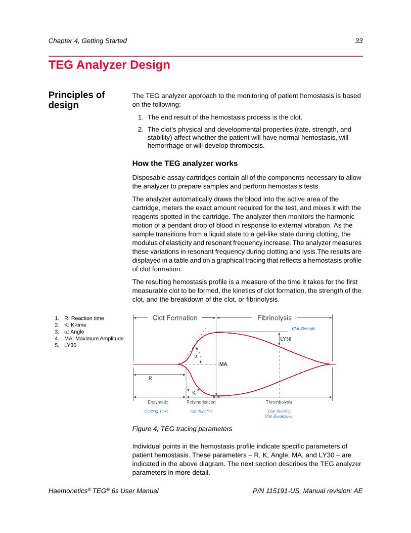
The resulting hemostasis profile is a measure of the time it takes for the first measurable clot to be formed, the kinetics of clot formation, the strength of the clot, and the breakdown of the clot, or fibrinolysis.
Figure 4, TEG tracing parameters
Individual points in the hemostasis profile indicate specific parameters of patient hemostasis. These parameters – R, K, Angle, MA, and LY30 – are indicated in the above diagram. The next section describes the TEG analyzer parameters in more detail.
1. R: Reaction time2. K: K-time3. α: Angle4. MA: Maximum Amplitude5. LY30
Haemonetics® TEG® 6s User Manual P/N 115191-US, Manual revision: AE
34 Chapter 4, Getting Started
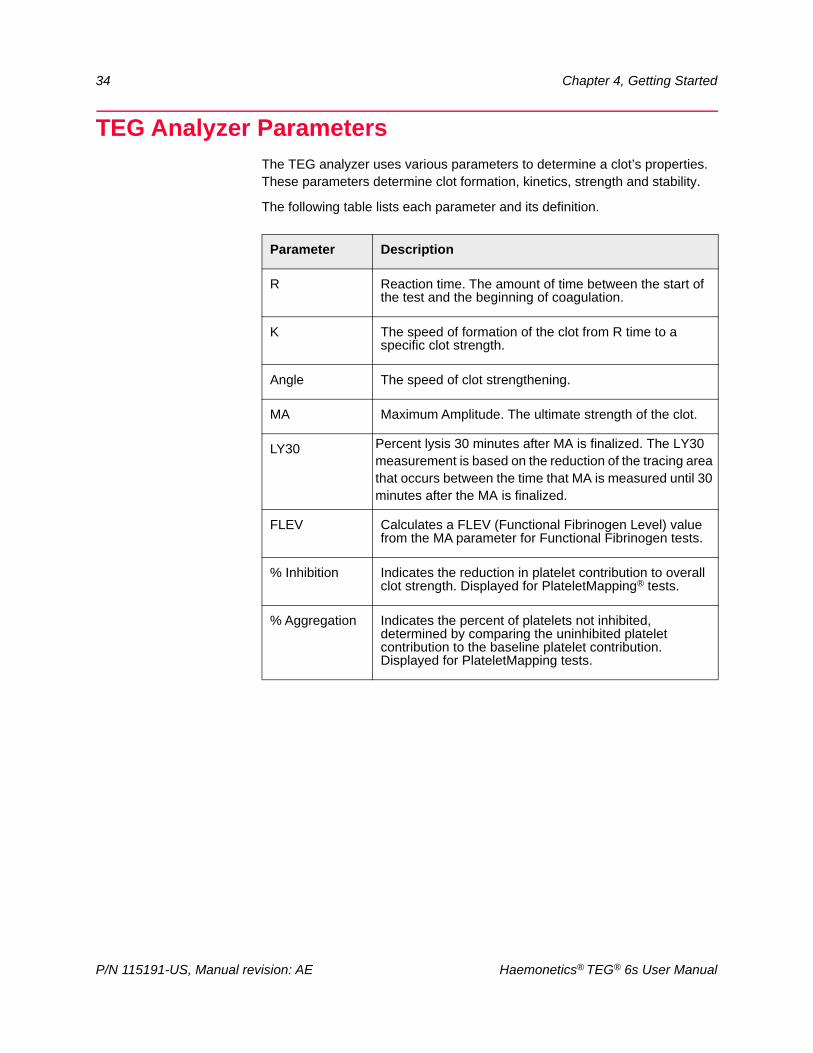
TEG Analyzer ParametersThe TEG analyzer uses various parameters to determine a clot’s properties. These parameters determine clot formation, kinetics, strength and stability.
The following table lists each parameter and its definition.
Parameter Description
R Reaction time. The amount of time between the start of the test and the beginning of coagulation.
K The speed of formation of the clot from R time to a specific clot strength.
Angle The speed of clot strengthening.
MA Maximum Amplitude. The ultimate strength of the clot.
LY30 Percent lysis 30 minutes after MA is finalized. The LY30 measurement is based on the reduction of the tracing area that occurs between the time that MA is measured until 30 minutes after the MA is finalized.
FLEV Calculates a FLEV (Functional Fibrinogen Level) value from the MA parameter for Functional Fibrinogen tests.
% Inhibition Indicates the reduction in platelet contribution to overall clot strength. Displayed for PlateletMapping® tests.
% Aggregation Indicates the percent of platelets not inhibited, determined by comparing the uninhibited platelet contribution to the baseline platelet contribution. Displayed for PlateletMapping tests.
P/N 115191-US, Manual revision: AE Haemonetics® TEG® 6s User Manual
Chapter 4, Getting Started 35
TEG Analyzer TestsHaemonetics provides various assay cartridges for use with the TEG analyzer. Refer to the included package inserts for an explanation of the tests, the reagents used, which parameters are measured, and the expected results.
Haemonetics® TEG® 6s User Manual P/N 115191-US, Manual revision: AE
36 Chapter 4, Getting Started
Setting Up and Logging into the Analyzer
Set up the analyzer
In most cases, a Haemonetics representative is responsible for the initial unpacking and setup of the TEG analyzer. The following setup instructions are provided in the event that a repaired analyzer is shipped back to you or that you need to relocate the analyzer.
Unpack the analyzer
1. From the shipping box, remove the small box containing the power supply and extra ferrite clamp.
Note: The ferrite clamp is for installations where an Ethernet cable will be permanently connected to the analyzer. For more information about installing the clamp on the Ethernet cable and setting up a network connection, refer to the TEG 6s Site Administrator Guide (116420-IE).
2. Remove the top foam supports and open the plastic bag.
3. Grasp the analyzer by the handle and lift it out of the shipping box.
Position the analyzer
Set up the TEG analyzer in location that is reasonably flat and level, and where the analyzer will be protected from accidental damage. See “Storing and handling the analyzer” on page 26 for complete guidelines on how to correctly place the analyzer.
Connect the analyzer to power
Screw the smaller end of the power cord onto the power jack at the back of the analyzer, and then plug the other end into a grounded wall outlet.
Attention: Always plug the power cord into the analyzer first, then into the wall outlet. This prevents the possibility of electrical shorting or power supply damage.
Note: Haemonetics recommends the use of a UPS (Uninterruptible Power Supply) between the analyzer and the wall outlet. This would allow a test to run to completion in the event of a power loss.
P/N 115191-US, Manual revision: AE Haemonetics® TEG® 6s User Manual
Chapter 4, Getting Started 37
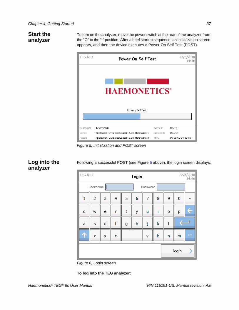
Start the analyzer
To turn on the analyzer, move the power switch at the rear of the analyzer from the "O" to the "I" position. After a brief startup sequence, an initialization screen appears, and then the device executes a Power-On Self Test (POST).
Figure 5, Initialization and POST screen
Log into the analyzer
Following a successful POST (see Figure 5 above), the login screen displays.
Figure 6, Login screen
To log into the TEG analyzer:
Haemonetics® TEG® 6s User Manual P/N 115191-US, Manual revision: AE
38 Chapter 4, Getting Started
1. On the Login screen, enter your user name in the Username box using the touch screen keyboard or hand-held barcode scanner.
2. Move the cursor to the Password box by doing one of the following:
Touch the Password box
Touch the return key
3. Enter your password, and then touch login.
Note: Depending on the user role that has been assigned to you, a password may not be required.
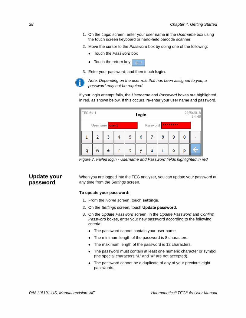
If your login attempt fails, the Username and Password boxes are highlighted in red, as shown below. If this occurs, re-enter your user name and password.
Figure 7, Failed login - Username and Password fields highlighted in red
Update your password
When you are logged into the TEG analyzer, you can update your password at any time from the Settings screen.
To update your password:
1. From the Home screen, touch settings.
2. On the Settings screen, touch Update password.
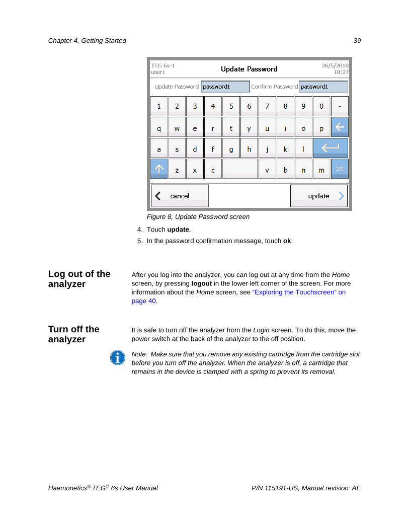
3. On the Update Password screen, in the Update Password and Confirm Password boxes, enter your new password according to the following criteria:
The password cannot contain your user name.
The minimum length of the password is 8 characters.
The maximum length of the password is 12 characters.
The password must contain at least one numeric character or symbol (the special characters “&” and “#” are not accepted).
The password cannot be a duplicate of any of your previous eight passwords.
P/N 115191-US, Manual revision: AE Haemonetics® TEG® 6s User Manual
Chapter 4, Getting Started 39
Figure 8, Update Password screen
4. Touch update.
5. In the password confirmation message, touch ok.
Log out of the analyzer
After you log into the analyzer, you can log out at any time from the Home screen, by pressing logout in the lower left corner of the screen. For more information about the Home screen, see “Exploring the Touchscreen” on page 40.
Turn off the analyzer
It is safe to turn off the analyzer from the Login screen. To do this, move the power switch at the back of the analyzer to the off position.
Note: Make sure that you remove any existing cartridge from the cartridge slot before you turn off the analyzer. When the analyzer is off, a cartridge that remains in the device is clamped with a spring to prevent its removal.
Haemonetics® TEG® 6s User Manual P/N 115191-US, Manual revision: AE
40 Chapter 4, Getting Started
Exploring the TouchscreenThis section provides a brief overview of the screens and icons that are displayed on the TEG analyzer touchscreen.
The touchscreen is designed to be intuitive and easy to use. During all analyzer operations, a button at the lower right of the touch screen takes you forward to the next step of the workflow, while a button at the lower left returns you to the previous step.
On every screen, the device name and username of the person who logged in displays in the upper left corner, and the system date and time displays in the upper right corner.
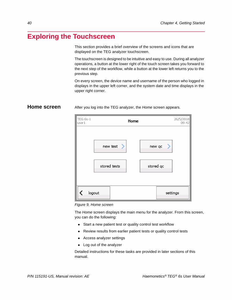
Home screen After you log into the TEG analyzer, the Home screen appears.
Figure 9, Home screen
The Home screen displays the main menu for the analyzer. From this screen, you can do the following:
Start a new patient test or quality control test workflow
Review results from earlier patient tests or quality control tests
Access analyzer settings
Log out of the analyzer
Detailed instructions for these tasks are provided in later sections of this manual.
P/N 115191-US, Manual revision: AE Haemonetics® TEG® 6s User Manual
Chapter 4, Getting Started 41
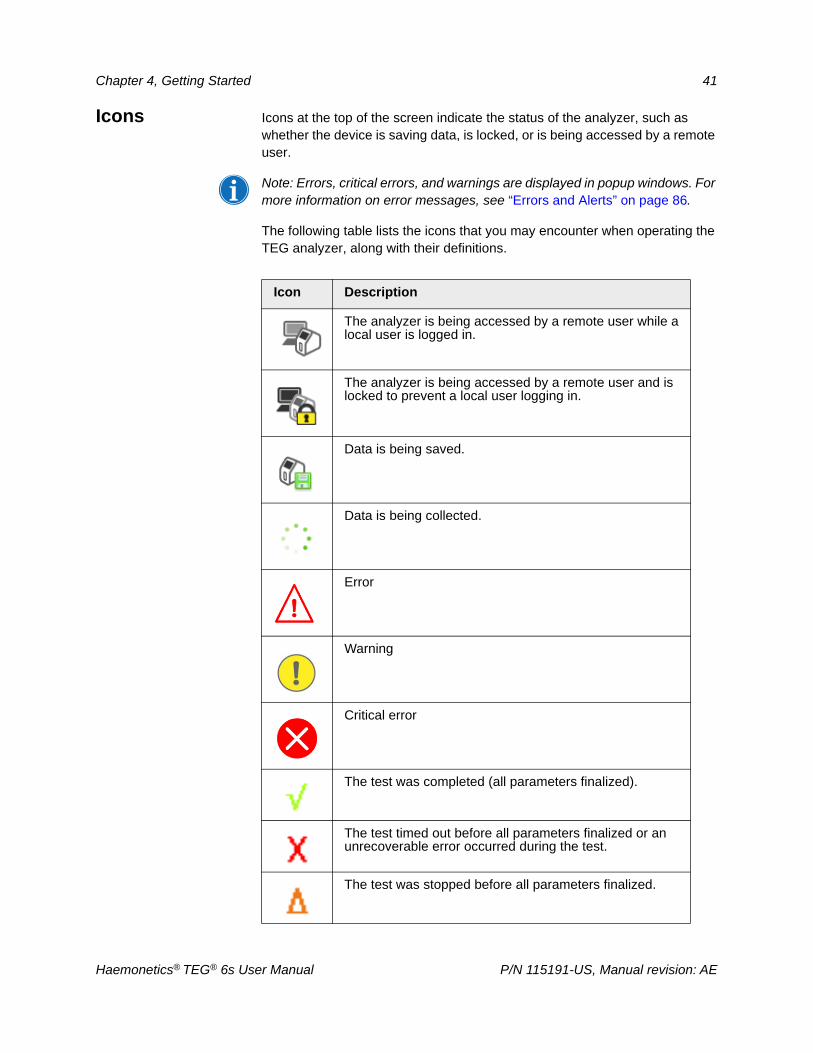
Icons Icons at the top of the screen indicate the status of the analyzer, such as whether the device is saving data, is locked, or is being accessed by a remote user.
Note: Errors, critical errors, and warnings are displayed in popup windows. For more information on error messages, see “Errors and Alerts” on page 86.
The following table lists the icons that you may encounter when operating the TEG analyzer, along with their definitions.
Icon Description
The analyzer is being accessed by a remote user while a local user is logged in.
The analyzer is being accessed by a remote user and is locked to prevent a local user logging in.
Data is being saved.
Data is being collected.
Error
Warning
Critical error
The test was completed (all parameters finalized).
The test timed out before all parameters finalized or an unrecoverable error occurred during the test.
The test was stopped before all parameters finalized.
Haemonetics® TEG® 6s User Manual P/N 115191-US, Manual revision: AE
42 Chapter 4, Getting Started
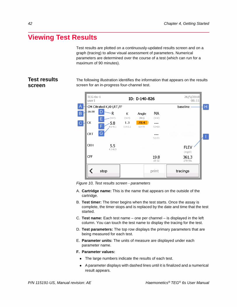
Viewing Test ResultsTest results are plotted on a continuously-updated results screen and on a graph (tracing) to allow visual assessment of parameters. Numerical parameters are determined over the course of a test (which can run for a maximum of 90 minutes).
Test results screen
The following illustration identifies the information that appears on the results screen for an in-progress four-channel test.
Figure 10, Test results screen - parameters
A. Cartridge name: This is the name that appears on the outside of the cartridge.
B. Test timer: The timer begins when the test starts. Once the assay is complete, the timer stops and is replaced by the date and time that the test started.
C. Test name: Each test name – one per channel – is displayed in the left column. You can touch the test name to display the tracing for the test.
D. Test parameters: The top row displays the primary parameters that are being measured for each test.
E. Parameter units: The units of measure are displayed under each parameter name.
F. Parameter values:
The large numbers indicate the results of each test.
A parameter displays with dashed lines until it is finalized and a numerical result appears.
P/N 115191-US, Manual revision: AE Haemonetics® TEG® 6s User Manual
Chapter 4, Getting Started 43
Not all parameters are applicable or calculated for all tests; any parameter that is not calculated for a test remains blank.
A parameter displays with an asterisk if it cannot be defined due to the timing or value of the MA parameter.
If a finalized parameter falls outside of the expected range, it is highlighted in orange and an exclamation mark appears next to the number.
G. Reference ranges: The maximum and minimum limits for normal results for each parameter appear under the parameter values.
H. Test information: The information that is added for the test in the Test information screen displays at the top right of the screen.
I. Additional parameters: If additional parameters are calculated for any test, they display in the right column.
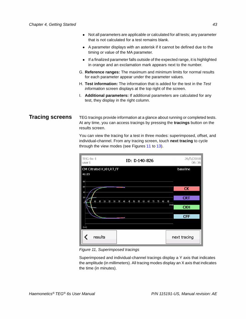
Tracing screens TEG tracings provide information at a glance about running or completed tests. At any time, you can access tracings by pressing the tracings button on the results screen.
You can view the tracing for a test in three modes: superimposed, offset, and individual-channel. From any tracing screen, touch next tracing to cycle through the view modes (see Figures 11 to 13).
Figure 11, Superimposed tracings
Superimposed and individual-channel tracings display a Y axis that indicates the amplitude (in millimeters). All tracing modes display an X axis that indicates the time (in minutes).
Haemonetics® TEG® 6s User Manual P/N 115191-US, Manual revision: AE
44 Chapter 4, Getting Started
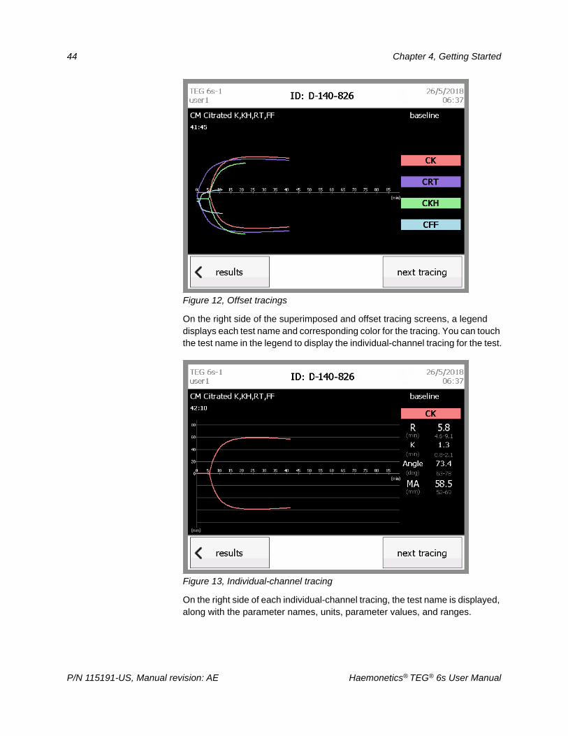
Figure 12, Offset tracings
On the right side of the superimposed and offset tracing screens, a legend displays each test name and corresponding color for the tracing. You can touch the test name in the legend to display the individual-channel tracing for the test.
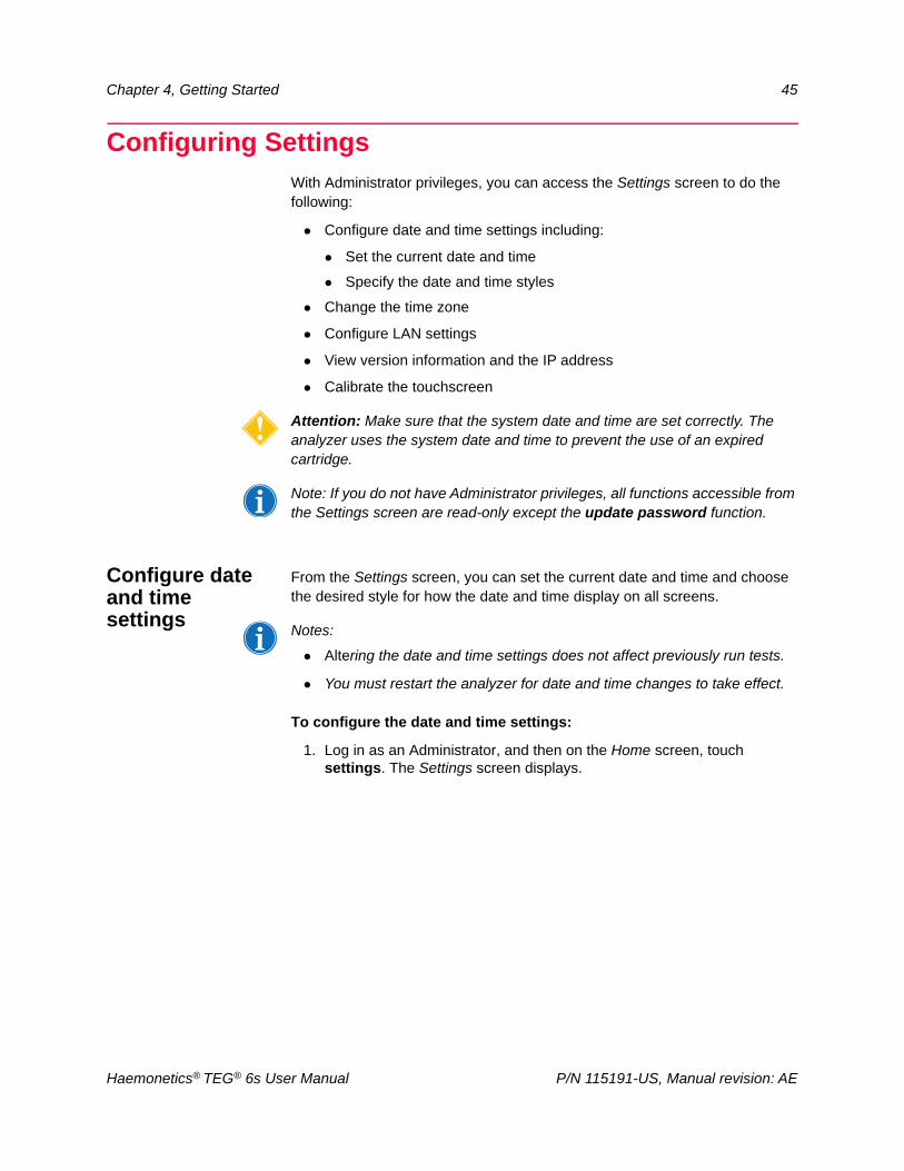
Figure 13, Individual-channel tracing
On the right side of each individual-channel tracing, the test name is displayed, along with the parameter names, units, parameter values, and ranges.
P/N 115191-US, Manual revision: AE Haemonetics® TEG® 6s User Manual
Chapter 4, Getting Started 45
Configuring SettingsWith Administrator privileges, you can access the Settings screen to do the following:
Configure date and time settings including:
Set the current date and time
Specify the date and time styles
Change the time zone
Configure LAN settings
View version information and the IP address
Calibrate the touchscreen
Attention: Make sure that the system date and time are set correctly. The analyzer uses the system date and time to prevent the use of an expired cartridge.
Note: If you do not have Administrator privileges, all functions accessible from the Settings screen are read-only except the update password function.
Configure date and time settings
From the Settings screen, you can set the current date and time and choose the desired style for how the date and time display on all screens.
Notes:
Altering the date and time settings does not affect previously run tests.
You must restart the analyzer for date and time changes to take effect.
To configure the date and time settings:
1. Log in as an Administrator, and then on the Home screen, touch settings. The Settings screen displays.
Haemonetics® TEG® 6s User Manual P/N 115191-US, Manual revision: AE
46 Chapter 4, Getting Started
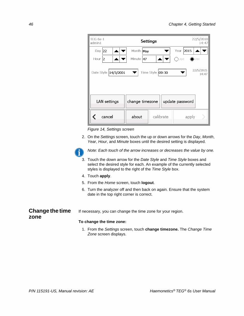
Figure 14, Settings screen
2. On the Settings screen, touch the up or down arrows for the Day, Month, Year, Hour, and Minute boxes until the desired setting is displayed.
Note: Each touch of the arrow increases or decreases the value by one.
3. Touch the down arrow for the Date Style and Time Style boxes and select the desired style for each. An example of the currently selected styles is displayed to the right of the Time Style box.
4. Touch apply.
5. From the Home screen, touch logout.
6. Turn the analyzer off and then back on again. Ensure that the system date in the top right corner is correct.
Change the time zone
If necessary, you can change the time zone for your region.
To change the time zone:
1. From the Settings screen, touch change timezone. The Change Time Zone screen displays.
P/N 115191-US, Manual revision: AE Haemonetics® TEG® 6s User Manual
Chapter 4, Getting Started 47
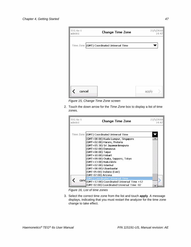
Figure 15, Change Time Zone screen
2. Touch the down arrow for the Time Zone box to display a list of time zones.
Figure 16, List of time zones
3. Select the correct time zone from the list and touch apply. A message displays, indicating that you must restart the analyzer for the time zone change to take effect.
Haemonetics® TEG® 6s User Manual P/N 115191-US, Manual revision: AE
48 Chapter 4, Getting Started
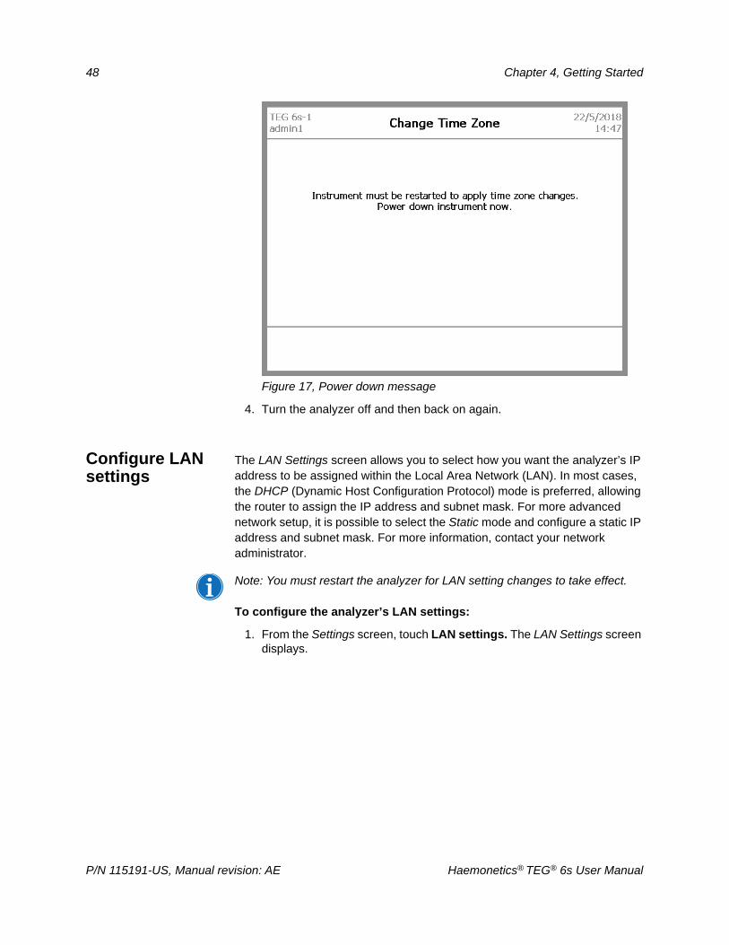
Figure 17, Power down message
4. Turn the analyzer off and then back on again.
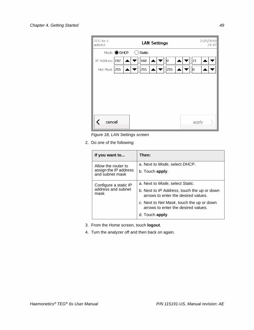
Configure LAN settings
The LAN Settings screen allows you to select how you want the analyzer’s IP address to be assigned within the Local Area Network (LAN). In most cases, the DHCP (Dynamic Host Configuration Protocol) mode is preferred, allowing the router to assign the IP address and subnet mask. For more advanced network setup, it is possible to select the Static mode and configure a static IP address and subnet mask. For more information, contact your network administrator.
Note: You must restart the analyzer for LAN setting changes to take effect.
To configure the analyzer’s LAN settings:
1. From the Settings screen, touch LAN settings. The LAN Settings screen displays.
P/N 115191-US, Manual revision: AE Haemonetics® TEG® 6s User Manual
Chapter 4, Getting Started 49
Figure 18, LAN Settings screen
2. Do one of the following:
3. From the Home screen, touch logout.
4. Turn the analyzer off and then back on again.
If you want to... Then:
Allow the router to assign the IP address and subnet mask
a. Next to Mode, select DHCP.
b. Touch apply.
Configure a static IP address and subnet mask
a. Next to Mode, select Static.
b. Next to IP Address, touch the up or down arrows to enter the desired values.
c. Next to Net Mask, touch the up or down arrows to enter the desired values.
d. Touch apply.
Haemonetics® TEG® 6s User Manual P/N 115191-US, Manual revision: AE
50 Chapter 4, Getting Started
Calibrate the touchscreen
Haemonetics recommends that the touchscreen be calibrated upon first use or installation. This ensures that the touch screen responds in the correct place. It should not be necessary to calibrate the touchscreen more than once in the lifetime of the analyzer.
To calibrate the touchscreen:
1. From the Settings screen, touch calibrate.
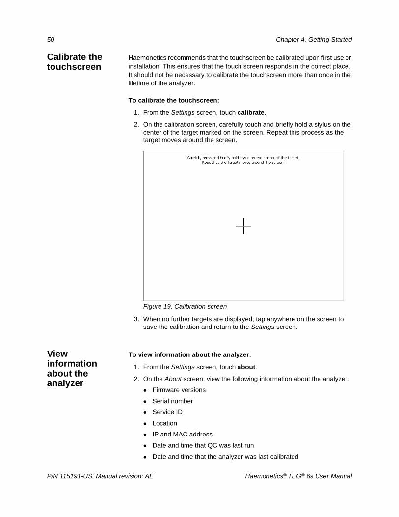
2. On the calibration screen, carefully touch and briefly hold a stylus on the center of the target marked on the screen. Repeat this process as the target moves around the screen.
Figure 19, Calibration screen
3. When no further targets are displayed, tap anywhere on the screen to save the calibration and return to the Settings screen.
View information about the analyzer
To view information about the analyzer:
1. From the Settings screen, touch about.
2. On the About screen, view the following information about the analyzer:
Firmware versions
Serial number
Service ID
Location
IP and MAC address
Date and time that QC was last run
Date and time that the analyzer was last calibrated
P/N 115191-US, Manual revision: AE Haemonetics® TEG® 6s User Manual
Chapter 4, Getting Started 51
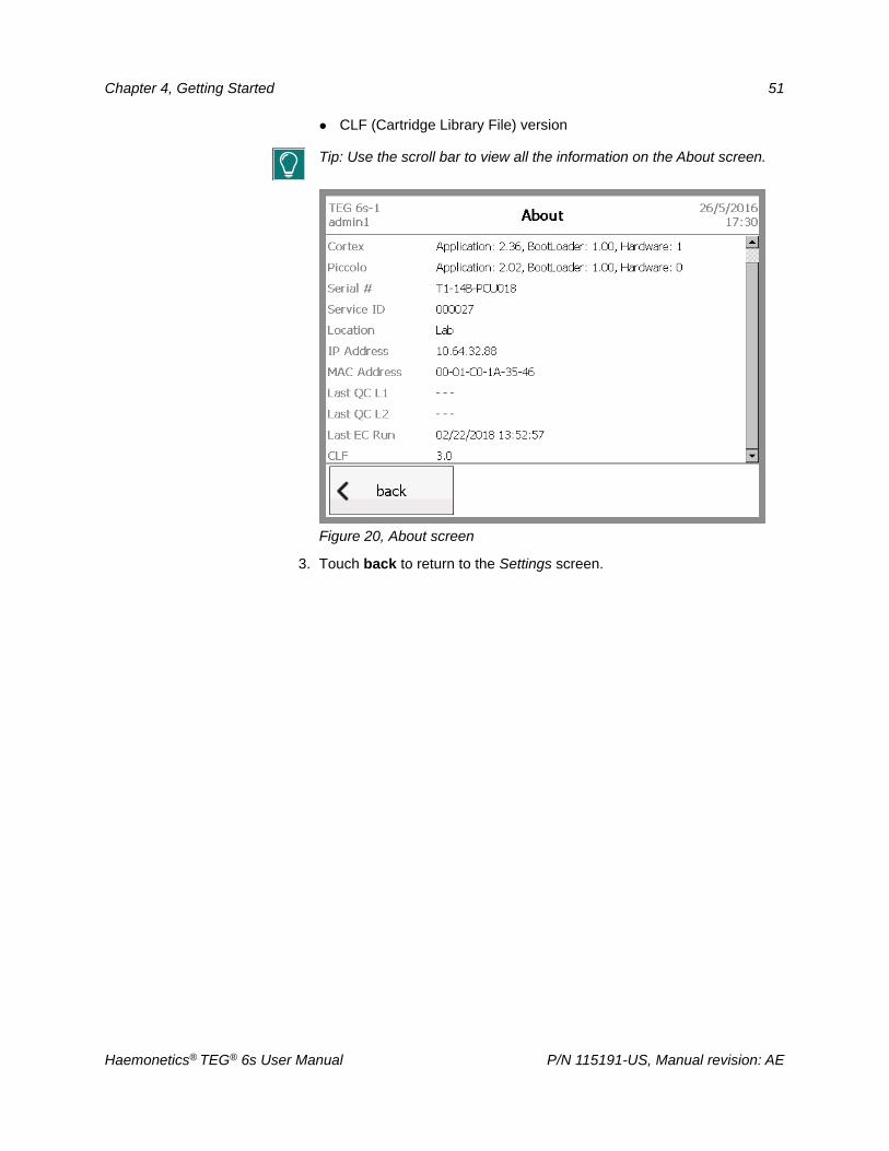
CLF (Cartridge Library File) version
Tip: Use the scroll bar to view all the information on the About screen.
Figure 20, About screen
3. Touch back to return to the Settings screen.
Haemonetics® TEG® 6s User Manual P/N 115191-US, Manual revision: AE

Chapter 5
Operating the TEG® Analyzer
Operation Overview . . . . . . . . . . . . . . . . . . . . . . . . . . . . . . . . . . . . . . . . . . .54Disposable assay cartridges . . . . . . . . . . . . . . . . . . . . . . . . . . . . . . . . . .54Blood samples . . . . . . . . . . . . . . . . . . . . . . . . . . . . . . . . . . . . . . . . . . . . .54
Running a Patient Test . . . . . . . . . . . . . . . . . . . . . . . . . . . . . . . . . . . . . . . . .56Quick guide for running a patient test . . . . . . . . . . . . . . . . . . . . . . . . . . .56Detailed guide for running a patient test . . . . . . . . . . . . . . . . . . . . . . . . .56
Stopping a Test . . . . . . . . . . . . . . . . . . . . . . . . . . . . . . . . . . . . . . . . . . . . . . .64Viewing Stored Patient Data. . . . . . . . . . . . . . . . . . . . . . . . . . . . . . . . . . . . .66
Quick guide for viewing stored patient data. . . . . . . . . . . . . . . . . . . . . . .66Detailed guide for viewing stored patient data. . . . . . . . . . . . . . . . . . . . .66
Haemonetics® TEG® 6s User Manual P/N 115191-US, Manual revision: AE
54 Chapter 5, Operating the TEG® Analyzer
Operation OverviewThis chapter explains how to operate the TEG® 6s analyzer and includes instructions for the following:
Running a patient test
Stopping a test
Viewing stored patient data
Attention: Before running tests on the TEG analyzer, you should be familiar with all necessary safety precautions outlined in Chapter 3, "Safety and Precautions".
Note: Before running tests, ensure that the system date and time displayed in the top right corner of the display screen is correct. See “Configure date and time settings” on page 45 for more information.
Disposable assay cartridges
Haemonetics disposable assay cartridges should be kept in their sealed pouches and in the specified storage conditions before use. Refer to each package insert for storage and handling instructions.
Before opening the cartridge pouch, verify that you have the proper cartridge for the assay you wish to run. Tear the pouch at the provided notch to remove the cartridge and then place the cartridge in the analyzer when prompted.
Inserting the cartridge triggers a barcode scan and pretest of the cartridge. At the successful completion of the pretest, the analyzer prompts you to verify that the assay being run is what is intended.
In the event that the cartridge pretest fails, the analyzer prompts you to insert a new cartridge or contact service personnel if the problem persists.
Attention: DO NOT remove a cartridge until prompted to do so, either after normal completion of the test or as a result of choosing to stop the test.
Blood samples Blood should be drawn by a trained phlebotomist following proper techniques and standards. Depending on the test, either citrated or heparinized blood
should be drawn into a matching Vacutainer® tube.
Notes:
To ensure accurate results, draw a discard tube first. Use a no-additive tube or a citrate tube marked “discard.” Using a plain serum tube for the discard draw is not recommended as these can contain clot activators.
All blood tubes must be filled completely (until vacuum is exhausted). A short draw is not an acceptable sample.
Never check for clots in a TEG blood sample by using a wooden stick. Always check for clots visually.
P/N 115191-US, Manual revision: AE Haemonetics® TEG® 6s User Manual

Chapter 5, Operating the TEG® Analyzer 55
Refer to the cartridge assay package inserts for recommendations regarding the timing window for sample testing (how soon the sample can be run and how long the sample is viable after being drawn).
Haemonetics® TEG® 6s User Manual P/N 115191-US, Manual revision: AE
56 Chapter 5, Operating the TEG® Analyzer
Running a Patient Test
Quick guide for running a patient test
1. From the Home screen, touch new test.
2. On the Select Patient screen, select the patient ID you wish to use. If the patient is not listed, add a new patient by pressing + and entering a patient ID on the Add Patient screen. Then touch next.
3. Insert the cartridge into the slot, as indicated on the screen, with the bar code on the left side.
4. Verify that the cartridge type is correct, and then touch next.
5. On the Test Information screen, enter information for the test, and then touch next.
6. Add blood to the cartridge sample port, filling up to or above the line marked on the cartridge, and then touch next.
7. View the test results on the results and/or tracing screens.
8. When prompted to remove the cartridge, dispose of it properly.
9. Touch done to return to the main menu.
Detailed guide for running a patient test
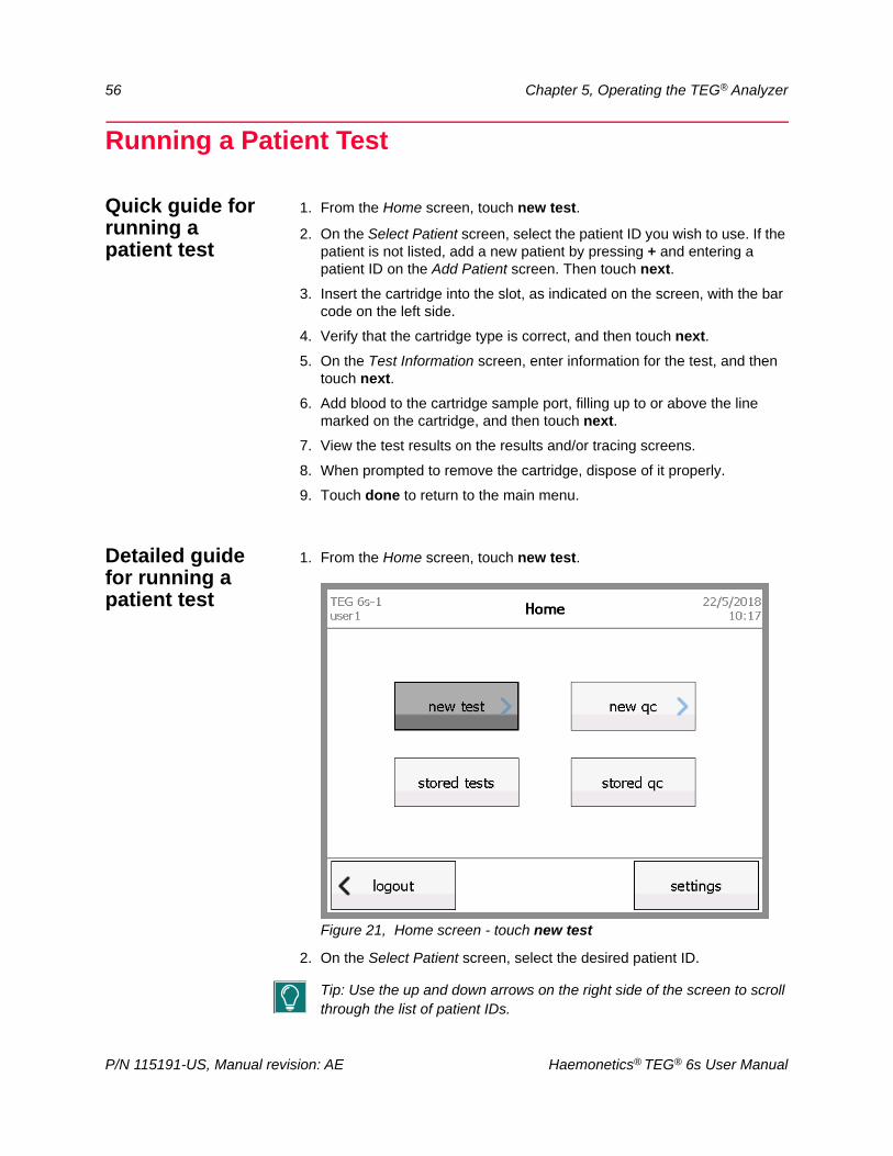
1. From the Home screen, touch new test.
Figure 21, Home screen - touch new test
2. On the Select Patient screen, select the desired patient ID.
Tip: Use the up and down arrows on the right side of the screen to scroll through the list of patient IDs.
P/N 115191-US, Manual revision: AE Haemonetics® TEG® 6s User Manual
Chapter 5, Operating the TEG® Analyzer 57
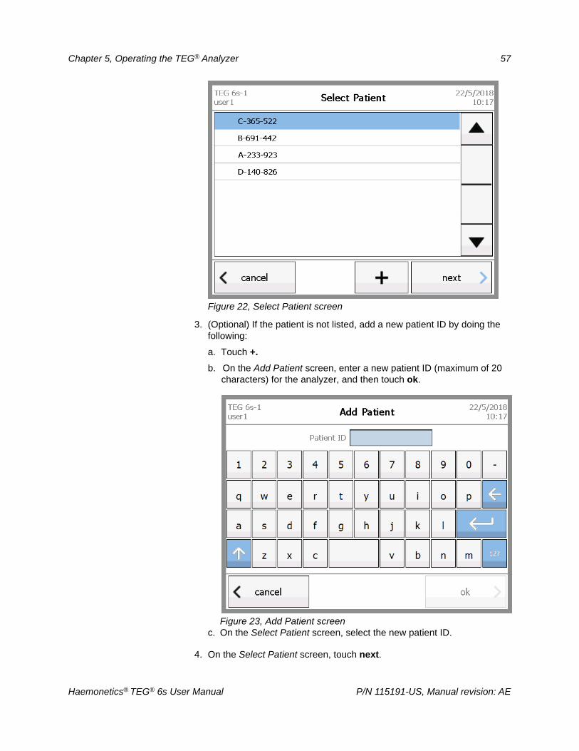
Figure 22, Select Patient screen
3. (Optional) If the patient is not listed, add a new patient ID by doing the following:
a. Touch +.
b. On the Add Patient screen, enter a new patient ID (maximum of 20 characters) for the analyzer, and then touch ok.
Figure 23, Add Patient screenc. On the Select Patient screen, select the new patient ID.
4. On the Select Patient screen, touch next.
Haemonetics® TEG® 6s User Manual P/N 115191-US, Manual revision: AE

58 Chapter 5, Operating the TEG® Analyzer
5. If the analyzer is linked to TEG Manager software and a laboratory information system (LIS), the Confirm Patient Data screen displays the ID, name, date of birth, and gender of the patient.
Figure 24, Confirm Patient Data screen
Do one of the following:
Touch confirm if the patient information is correct.
Touch reject if the patient information is incorrect.
In the confirmation message that appears, touch yes if you wish to continue the test with rejected patient data, or touch no to return to the Select Patient screen.
6. Remove the desired patient test cartridge from its sealed pouch.
7. Insert the cartridge into the slot, as indicated on the Preparing Test – Insert cartridge screen, with the bar code on the left side.
Note: Only a Haemonetics assay cartridge can be inserted into the cartridge slot. Check the label to be sure you are using the intended assay.
P/N 115191-US, Manual revision: AE Haemonetics® TEG® 6s User Manual
Chapter 5, Operating the TEG® Analyzer 59
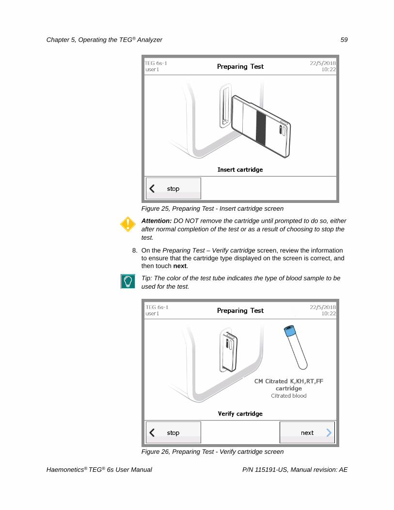
Figure 25, Preparing Test - Insert cartridge screen
Attention: DO NOT remove the cartridge until prompted to do so, either after normal completion of the test or as a result of choosing to stop the test.
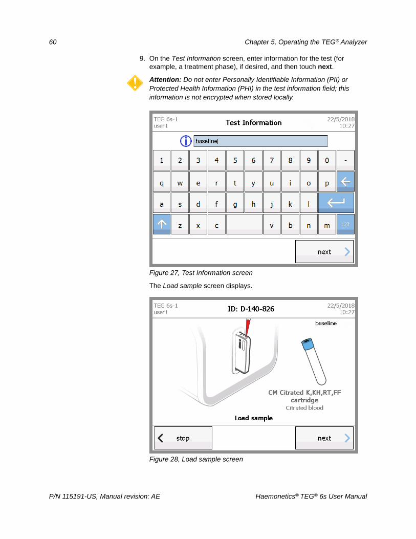
8. On the Preparing Test – Verify cartridge screen, review the information to ensure that the cartridge type displayed on the screen is correct, and then touch next.
Tip: The color of the test tube indicates the type of blood sample to be used for the test.
Figure 26, Preparing Test - Verify cartridge screen
Haemonetics® TEG® 6s User Manual P/N 115191-US, Manual revision: AE
60 Chapter 5, Operating the TEG® Analyzer
9. On the Test Information screen, enter information for the test (for example, a treatment phase), if desired, and then touch next.
Attention: Do not enter Personally Identifiable Information (PII) or Protected Health Information (PHI) in the test information field; this information is not encrypted when stored locally.
Figure 27, Test Information screen
The Load sample screen displays.
Figure 28, Load sample screen
P/N 115191-US, Manual revision: AE Haemonetics® TEG® 6s User Manual
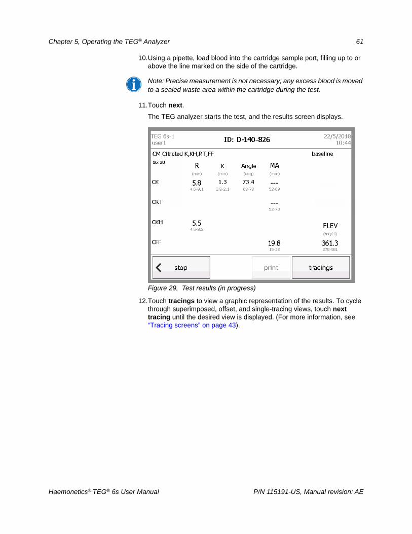
Chapter 5, Operating the TEG® Analyzer 61
10.Using a pipette, load blood into the cartridge sample port, filling up to or above the line marked on the side of the cartridge.
Note: Precise measurement is not necessary; any excess blood is moved to a sealed waste area within the cartridge during the test.
11.Touch next.
The TEG analyzer starts the test, and the results screen displays.
Figure 29, Test results (in progress)
12.Touch tracings to view a graphic representation of the results. To cycle through superimposed, offset, and single-tracing views, touch next tracing until the desired view is displayed. (For more information, see “Tracing screens” on page 43).
Haemonetics® TEG® 6s User Manual P/N 115191-US, Manual revision: AE
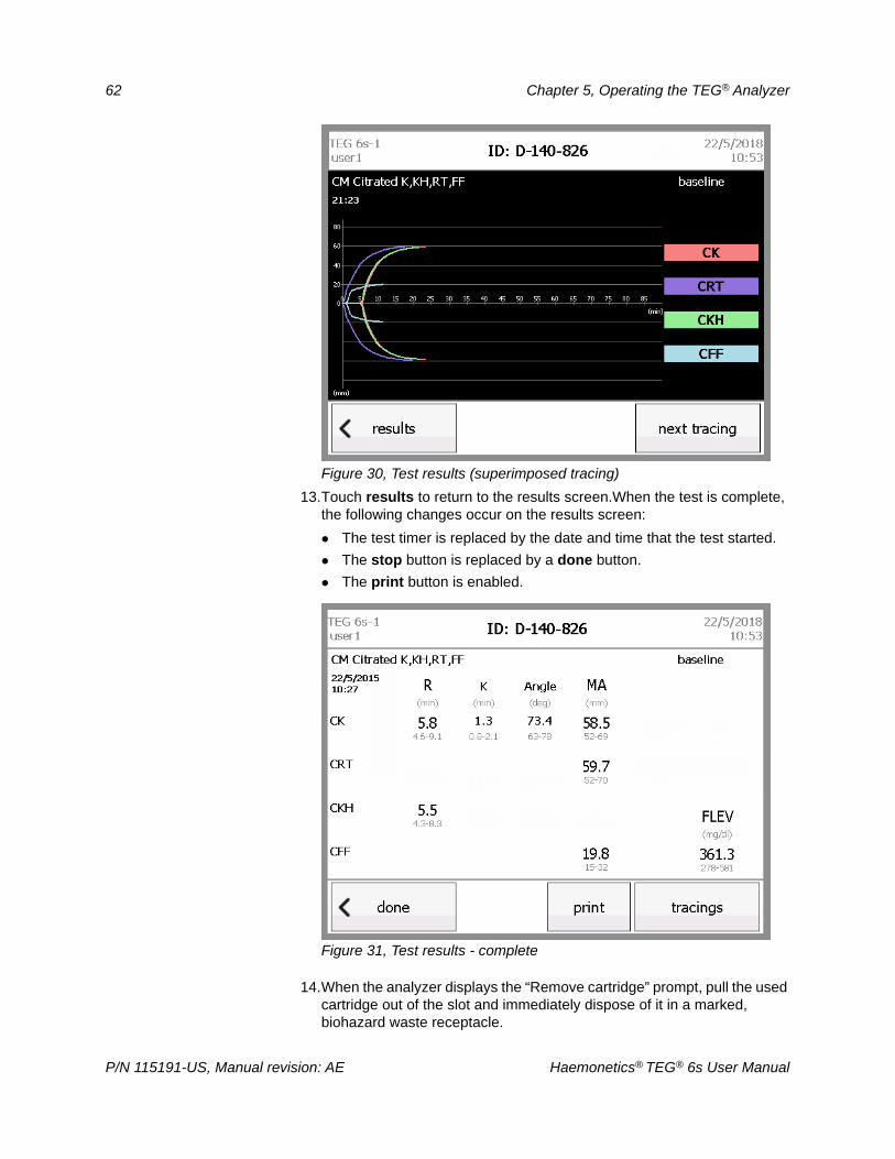
62 Chapter 5, Operating the TEG® Analyzer
Figure 30, Test results (superimposed tracing)
13.Touch results to return to the results screen.When the test is complete, the following changes occur on the results screen:
The test timer is replaced by the date and time that the test started.
The stop button is replaced by a done button.
The print button is enabled.
Figure 31, Test results - complete
14.When the analyzer displays the “Remove cartridge” prompt, pull the used cartridge out of the slot and immediately dispose of it in a marked, biohazard waste receptacle.
P/N 115191-US, Manual revision: AE Haemonetics® TEG® 6s User Manual
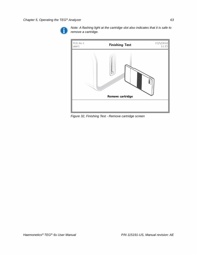
Chapter 5, Operating the TEG® Analyzer 63
Note: A flashing light at the cartridge slot also indicates that it is safe to remove a cartridge.
Figure 32, Finishing Test - Remove cartridge screen
Haemonetics® TEG® 6s User Manual P/N 115191-US, Manual revision: AE
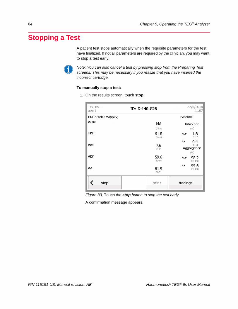
64 Chapter 5, Operating the TEG® Analyzer
Stopping a TestA patient test stops automatically when the requisite parameters for the test have finalized. If not all parameters are required by the clinician, you may want to stop a test early.
Note: You can also cancel a test by pressing stop from the Preparing Test screens. This may be necessary if you realize that you have inserted the incorrect cartridge.
To manually stop a test:
1. On the results screen, touch stop.
Figure 33, Touch the stop button to stop the test early
A confirmation message appears.
P/N 115191-US, Manual revision: AE Haemonetics® TEG® 6s User Manual
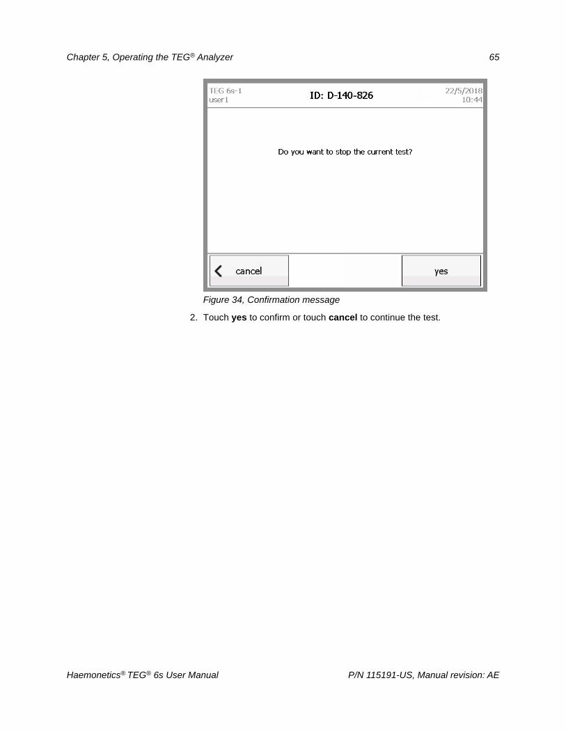
Chapter 5, Operating the TEG® Analyzer 65
Figure 34, Confirmation message
2. Touch yes to confirm or touch cancel to continue the test.
Haemonetics® TEG® 6s User Manual P/N 115191-US, Manual revision: AE
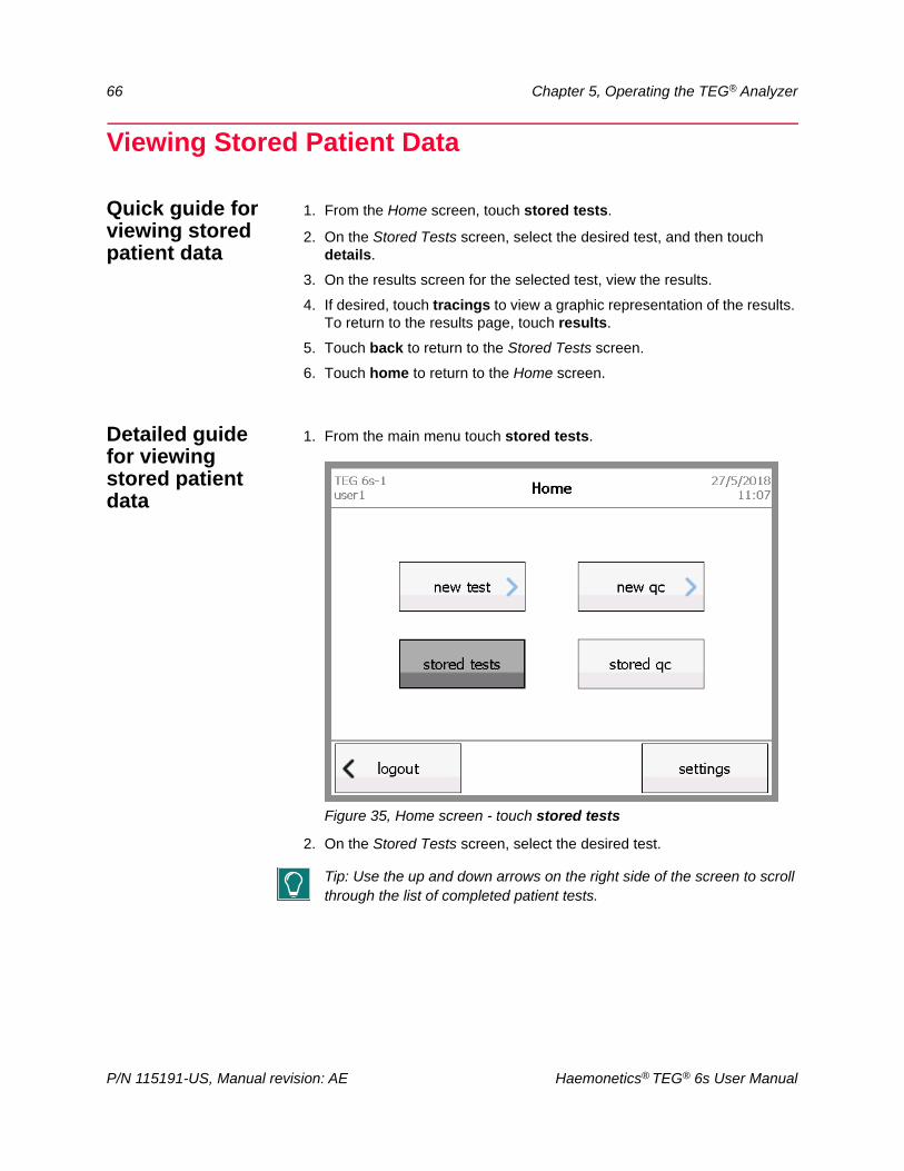
66 Chapter 5, Operating the TEG® Analyzer
Viewing Stored Patient Data
Quick guide for viewing stored patient data
1. From the Home screen, touch stored tests.
2. On the Stored Tests screen, select the desired test, and then touch details.
3. On the results screen for the selected test, view the results.
4. If desired, touch tracings to view a graphic representation of the results. To return to the results page, touch results.
5. Touch back to return to the Stored Tests screen.
6. Touch home to return to the Home screen.
Detailed guide for viewing stored patient data
1. From the main menu touch stored tests.
Figure 35, Home screen - touch stored tests
2. On the Stored Tests screen, select the desired test.
Tip: Use the up and down arrows on the right side of the screen to scroll through the list of completed patient tests.
P/N 115191-US, Manual revision: AE Haemonetics® TEG® 6s User Manual
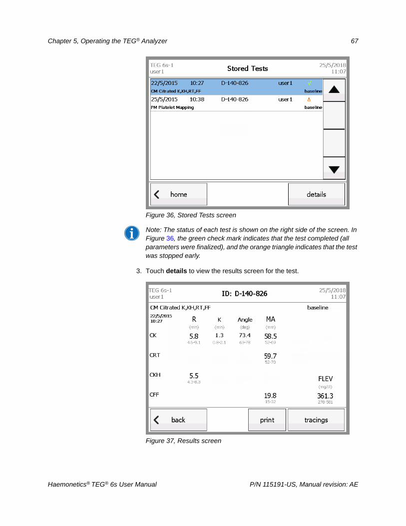
Chapter 5, Operating the TEG® Analyzer 67
Figure 36, Stored Tests screen
Note: The status of each test is shown on the right side of the screen. In Figure 36, the green check mark indicates that the test completed (all parameters were finalized), and the orange triangle indicates that the test was stopped early.
3. Touch details to view the results screen for the test.
Figure 37, Results screen
Haemonetics® TEG® 6s User Manual P/N 115191-US, Manual revision: AE
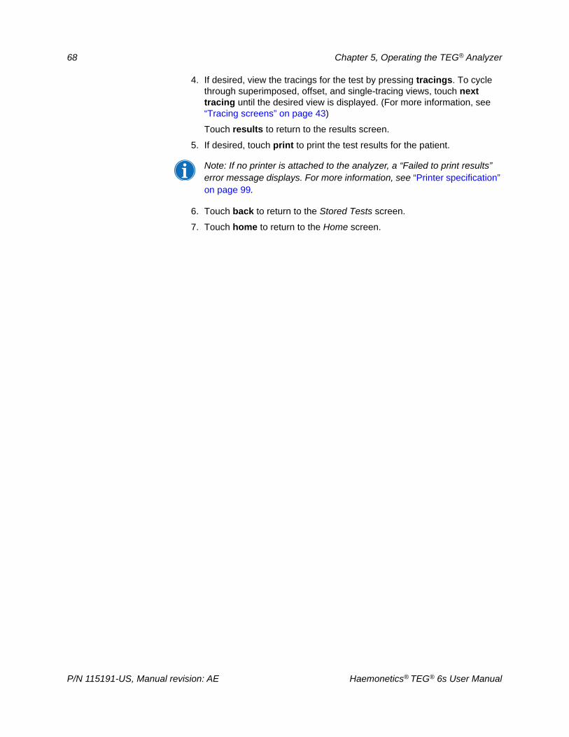
68 Chapter 5, Operating the TEG® Analyzer
4. If desired, view the tracings for the test by pressing tracings. To cycle through superimposed, offset, and single-tracing views, touch next tracing until the desired view is displayed. (For more information, see “Tracing screens” on page 43)
Touch results to return to the results screen.
5. If desired, touch print to print the test results for the patient.
Note: If no printer is attached to the analyzer, a “Failed to print results” error message displays. For more information, see “Printer specification” on page 99.
6. Touch back to return to the Stored Tests screen.
7. Touch home to return to the Home screen.
P/N 115191-US, Manual revision: AE Haemonetics® TEG® 6s User Manual
Chapter 6
Quality Control
Overview. . . . . . . . . . . . . . . . . . . . . . . . . . . . . . . . . . . . . . . . . . . . . . . . . . . .70IQCP . . . . . . . . . . . . . . . . . . . . . . . . . . . . . . . . . . . . . . . . . . . . . . . . . . . .70Analyzer Quality Control (internal QC) . . . . . . . . . . . . . . . . . . . . . . . . . .70Reagent Quality Control (external QC) . . . . . . . . . . . . . . . . . . . . . . . . . .71
Performing Citrated Reagent QC . . . . . . . . . . . . . . . . . . . . . . . . . . . . . . . . .72Citrated controls . . . . . . . . . . . . . . . . . . . . . . . . . . . . . . . . . . . . . . . . . . .72General procedure: run QC in a patient assay cartridge . . . . . . . . . . . . .72Run normal blood in a Citrated Multichannel or Citrated: K, RT, FF assay cartridge. . . . . . . . . . . . . . . . . . . . . . . . . . . . . . . . . . . . . . . . . . . . . . . . . .76Run Abnormal QC and Lysis QC in a Citrated: K, RT, FF cartridge . . . .84
Performing PlateletMapping® Reagent QC . . . . . . . . . . . . . . . . . . . . . . . . .86PlateletMapping controls . . . . . . . . . . . . . . . . . . . . . . . . . . . . . . . . . . . . .86
Viewing Stored QC Data. . . . . . . . . . . . . . . . . . . . . . . . . . . . . . . . . . . . . . . .88Quick guide for viewing stored QC data . . . . . . . . . . . . . . . . . . . . . . . . .88Detailed guide for viewing stored QC data . . . . . . . . . . . . . . . . . . . . . . .88
Haemonetics® TEG® 6s User Manual P/N 115191-US, Manual revision: AE
70 Chapter 6, Quality Control
Overview
This chapter provides an overview of TEG® 6s System quality control (QC) and explains how to do the following:
Establish normal and abnormal controls
Run QC checks on patient assay cartridge reagents
View stored QC data
IQCP Haemonetics recommends an Individualized Quality Control Plan (IQCP), based on ISO 14971, for QC of the TEG 6s System. For more information, refer
to Comprehensive TEG® 6s IQCP Aid with Risk Controls (CL102098).
Analyzer Quality Control (internal QC)
The TEG 6s analyzer and reagents have been designed and manufactured following ISO 14971 guidelines. Haemonetics has completed a thorough hazard identification, determined the severity and probability of harm, has estimated and evaluated risks, and has implemented design features to control and monitor risk, a crucial component in ISO 14971 risk control. The integrated analyzer quality control features are significant in this regard, providing mitigating factors for many system risks.
The TEG 6s analyzer is designed with the following internal, built-in Quality Control (QC) features that verify that all electromechanical and pneumatic functions of the analyzer-cartridge combination are operating satisfactorily:
Power-On Self Test (POST): When the power switch is moved to the “ON” position, the analyzer initiates the POST sequence. This performs QC tests on all analyzer functions prior to cartridge insertion. A failure of any component will report an error on the display screen and prevent further operation.
Pre-Test: When a cartridge is inserted into the slot, the analyzer performs a Pre-Test QC to verify the bar code reader’s ability to identify the cartridge and the integrity of the cartridge-analyzer interface. A failure of any component will report an error on the display screen and prevent further operation.
In-Use: When the operator adds the sample and starts the test, the analyzer’s internal QC functions monitor critical operational parameters throughout the duration of the test. At every step, if any critical operational parameter is found to be out of range it will be reported and the test will be invalidated.
Through the incorporation of these three levels of internal QC, all essential functions of the analyzer are checked and verified without the need for external QC materials.
P/N 115191-US, Manual revision: AE Haemonetics® TEG® 6s User Manual
Chapter 6, Quality Control 71
Reagent Quality Control (external QC)
Reagent cartridges are manufactured under current Good Manufacturing Practices (GMP) with a validated manufacturing process with in-process controls to ensure lot to lot reproducibility and product performance. A sampling of finished cartridges is subject to Quality Control testing to confirm product performance prior to lot release. An extensive stability program, including both accelerated and real-time aging, provides assurance that the cartridges will perform within specification when stored unopened in their original packaging at the recommended storage conditions until their expiration date.
Whereas the internal QC of the analyzer effectively tests all analyzer functions, a QC methodology may be required to verify that reagents in cartridges are still viable at time of use. This ensures that cartridges have not been mishandled between production and arrival at the lab, or have not been subject to adverse environmental conditions or otherwise mishandled while in lab storage. This can supplement the laboratory’s development of its own Individualized Quality Control Plan (IQCP) based on the lab’s risk analysis, in accordance with CLSI EP23. This risk analysis would take into account the lab’s specific situations that could affect reagent quality, such as environmental storage controls.
Haemonetics recommends that QC checks be performed for each new shipment of assay cartridges. Additional QC checks may be performed at predetermined intervals based on the laboratory’s quality control policies. The end user should follow the recommendations of local and state regulatory agencies as well as facility policies.
Haemonetics recommends that the lab perform two levels of QC testing, whenever indicated by the IQCP, using the procedures outlined in the following sections for each assay cartridge.
Haemonetics® TEG® 6s User Manual P/N 115191-US, Manual revision: AE
72 Chapter 6, Quality Control
Performing Citrated Reagent QC
Citrated controls
Haemonetics recommends using the following normal and abnormal controls when performing QC checks of a Citrated Multichannel (07-601-US) or Citrated: K, RT, FF (07-605-US) assay cartridge:
1. Establish a known normal quality control using blood drawn from a healthy adult.
The normal donor control should not have taken any medication known to affect coagulation levels (for example, blood thinners, hormone-based medications) and should have prior Citrated Multichannel or Citrated: K, RT, FF cartridge tests that have fallen within the established normal reference ranges.
The normal donor test results should fall within established reference ranges for all applicable parameters.
Note: For a complete list of medications that may affect coagulation levels, refer to the TEG 6s Validation Guide (118597-US).
2. Citrated Multichannel cartridge: Prepare an abnormal quality control using Abnormal QC (AQC) material, representing an abnormal sample, following instructions in the package insert for Abnormal QC (07-662-US).
3. Citrated: K, RT, FF cartridge: Prepare abnormal and lysis quality controls, using Abnormal QC and Lysis QC materials, representing abnormal samples, following instructions in the package insert for Abnormal & Lysis QC (07-663-US).
General procedure: run QC in a patient assaycartridge
This section outlines the general procedure for running QC material in a patient assay cartridge on the TEG 6s analyzer. The following steps are the same for all QC types: normal blood, Abnormal QC materials, and Lysis QC materials.
Note: Individual procedures and examples of results screens are presented later in this chapter. The illustrations in the following procedure show Lysis QC being run in a Citrated: K, RT, FF assay cartridge.
To perform a QC check on a patient assay cartridge:
1. Remove the patient assay cartridge pouch from refrigerated storage.
2. Tear open the pouch, remove the cartridge and discard the pouch and desiccant pack.
3. Prepare the QC sample (normal blood or QC materials) following the instructions in the applicable package insert.
4. From the Home screen on the TEG analyzer, select new qc.
P/N 115191-US, Manual revision: AE Haemonetics® TEG® 6s User Manual
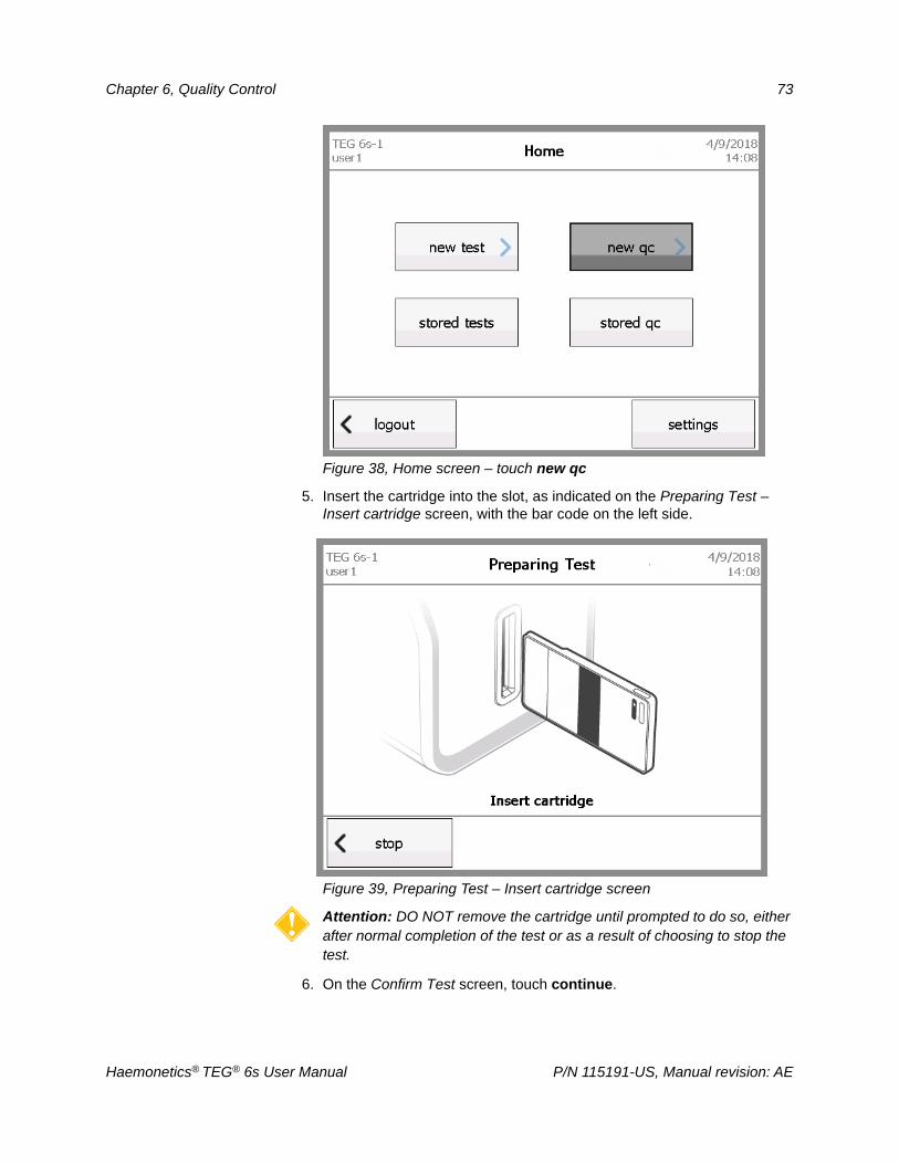
Chapter 6, Quality Control 73
Figure 38, Home screen – touch new qc
5. Insert the cartridge into the slot, as indicated on the Preparing Test –Insert cartridge screen, with the bar code on the left side.
Figure 39, Preparing Test – Insert cartridge screen
Attention: DO NOT remove the cartridge until prompted to do so, either after normal completion of the test or as a result of choosing to stop the test.
6. On the Confirm Test screen, touch continue.
Haemonetics® TEG® 6s User Manual P/N 115191-US, Manual revision: AE
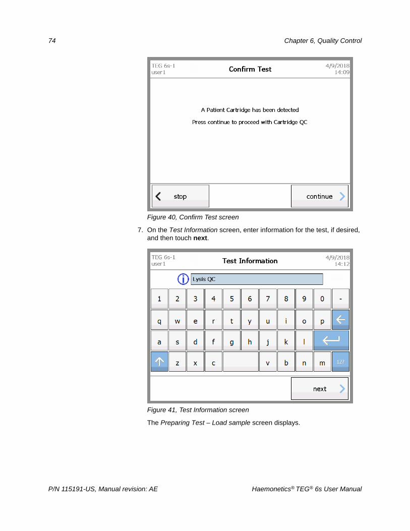
74 Chapter 6, Quality Control
Figure 40, Confirm Test screen
7. On the Test Information screen, enter information for the test, if desired, and then touch next.
Figure 41, Test Information screen
The Preparing Test – Load sample screen displays.
P/N 115191-US, Manual revision: AE Haemonetics® TEG® 6s User Manual
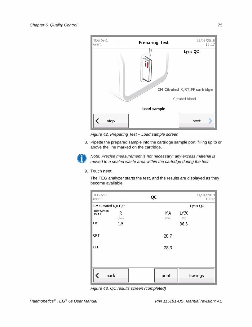
Chapter 6, Quality Control 75
Figure 42, Preparing Test – Load sample screen
8. Pipette the prepared sample into the cartridge sample port, filling up to or above the line marked on the cartridge.
Note: Precise measurement is not necessary; any excess material is moved to a sealed waste area within the cartridge during the test.
9. Touch next.
The TEG analyzer starts the test, and the results are displayed as they become available.
Figure 43, QC results screen (completed)
Haemonetics® TEG® 6s User Manual P/N 115191-US, Manual revision: AE
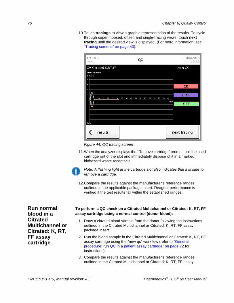
76 Chapter 6, Quality Control
10.Touch tracings to view a graphic representation of the results. To cycle through superimposed, offset, and single-tracing views, touch next tracing until the desired view is displayed. (For more information, see “Tracing screens” on page 43).
Figure 44, QC tracing screen
11.When the analyzer displays the “Remove cartridge” prompt, pull the used cartridge out of the slot and immediately dispose of it in a marked, biohazard waste receptacle.
Note: A flashing light at the cartridge slot also indicates that it is safe to remove a cartridge.
12.Compare the results against the manufacturer’s reference ranges outlined in the applicable package insert. Reagent performance is verified if the test results fall within the established ranges.
Run normal blood in a Citrated Multichannel or Citrated: K, RT, FF assay cartridge
To perform a QC check on a Citrated Multichannel or Citrated: K, RT, FF assay cartridge using a normal control (donor blood):
1. Draw a citrated blood sample from the donor following the instructions outlined in the Citrated Multichannel or Citrated: K, RT, FF assay package insert.
2. Run the blood sample in the Citrated Multichannel or Citrated: K, RT, FF assay cartridge using the “new qc” workflow (refer to “General procedure: run QC in a patient assay cartridge” on page 72 for instructions).
3. Compare the results against the manufacturer’s reference ranges outlined in the Citrated Multichannel or Citrated: K, RT, FF assay
P/N 115191-US, Manual revision: AE Haemonetics® TEG® 6s User Manual
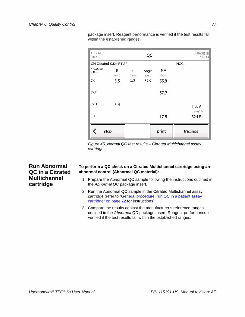
Chapter 6, Quality Control 77
package insert. Reagent performance is verified if the test results fall within the established ranges.
Figure 45, Normal QC test results – Citrated Multichannel assay cartridge
Run Abnormal QC in a Citrated Multichannel cartridge
To perform a QC check on a Citrated Multichannel cartridge using an abnormal control (Abnormal QC material):
1. Prepare the Abnormal QC sample following the instructions outlined in the Abnormal QC package insert.
2. Run the Abnormal QC sample in the Citrated Multichannel assay cartridge (refer to “General procedure: run QC in a patient assay cartridge” on page 72 for instructions).
3. Compare the results against the manufacturer’s reference ranges outlined in the Abnormal QC package insert. Reagent performance is verified if the test results fall within the established ranges.
Haemonetics® TEG® 6s User Manual P/N 115191-US, Manual revision: AE
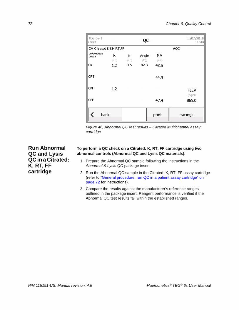
78 Chapter 6, Quality Control
Figure 46, Abnormal QC test results – Citrated Multichannel assay cartridge
Run Abnormal QC and Lysis QC in a Citrated: K, RT, FF cartridge
To perform a QC check on a Citrated: K, RT, FF cartridge using two abnormal controls (Abnormal QC and Lysis QC materials):
1. Prepare the Abnormal QC sample following the instructions in the Abnormal & Lysis QC package insert.
2. Run the Abnormal QC sample in the Citrated: K, RT, FF assay cartridge (refer to “General procedure: run QC in a patient assay cartridge” on page 72 for instructions).
3. Compare the results against the manufacturer’s reference ranges outlined in the package insert. Reagent performance is verified if the Abnormal QC test results fall within the established ranges.
P/N 115191-US, Manual revision: AE Haemonetics® TEG® 6s User Manual
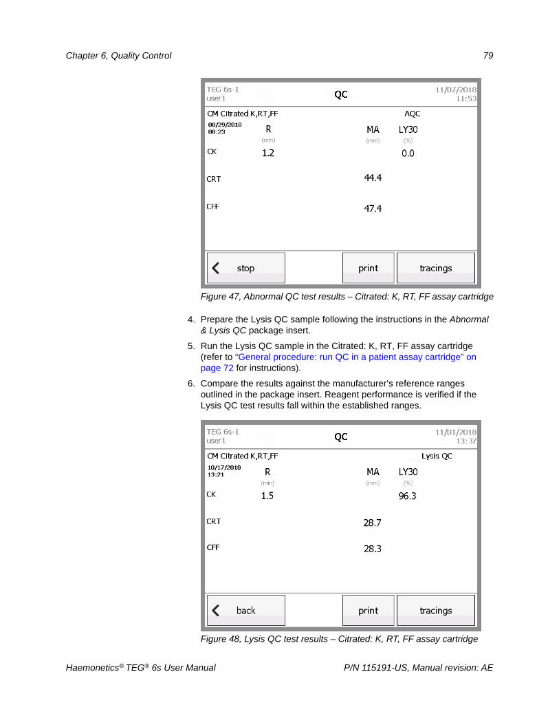
Chapter 6, Quality Control 79
Figure 47, Abnormal QC test results – Citrated: K, RT, FF assay cartridge
4. Prepare the Lysis QC sample following the instructions in the Abnormal & Lysis QC package insert.
5. Run the Lysis QC sample in the Citrated: K, RT, FF assay cartridge (refer to “General procedure: run QC in a patient assay cartridge” on page 72 for instructions).
6. Compare the results against the manufacturer’s reference ranges outlined in the package insert. Reagent performance is verified if the Lysis QC test results fall within the established ranges.
Figure 48, Lysis QC test results – Citrated: K, RT, FF assay cartridge
Haemonetics® TEG® 6s User Manual P/N 115191-US, Manual revision: AE
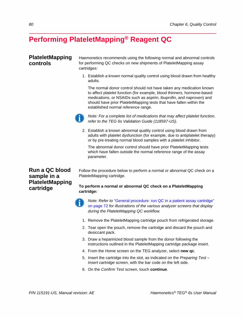
80 Chapter 6, Quality Control
Performing PlateletMapping® Reagent QC
PlateletMapping controls
Haemonetics recommends using the following normal and abnormal controls for performing QC checks on new shipments of PlateletMapping assay cartridges:
1. Establish a known normal quality control using blood drawn from healthy adults.
The normal donor control should not have taken any medication known to affect platelet function (for example, blood thinners, hormone-based medications, or NSAIDs such as aspirin, ibuprofin, and naproxen) and should have prior PlateletMapping tests that have fallen within the established normal reference range.
Note: For a complete list of medications that may affect platelet function, refer to the TEG 6s Validation Guide (118597-US).
2. Establish a known abnormal quality control using blood drawn from adults with platelet dysfunction (for example, due to antiplatelet therapy) or by pre-treating normal blood samples with a platelet inhibitor.
The abnormal donor control should have prior PlateletMapping tests which have fallen outside the normal reference range of the assay parameter.
Run a QC blood sample in a PlateletMapping cartridge
Follow the procedure below to perform a normal or abnormal QC check on a PlateletMapping cartridge.
To perform a normal or abnormal QC check on a PlateletMapping cartridge:
Note: Refer to “General procedure: run QC in a patient assay cartridge” on page 72 for illustrations of the various analyzer screens that display during the PlateletMapping QC workflow.
1. Remove the PlateletMapping cartridge pouch from refrigerated storage.
2. Tear open the pouch, remove the cartridge and discard the pouch and desiccant pack.
3. Draw a heparinized blood sample from the donor following the instructions outlined in the PlateletMapping cartridge package insert.
4. From the Home screen on the TEG analyzer, select new qc.
5. Insert the cartridge into the slot, as indicated on the Preparing Test –Insert cartridge screen, with the bar code on the left side.
6. On the Confirm Test screen, touch continue.
P/N 115191-US, Manual revision: AE Haemonetics® TEG® 6s User Manual
Chapter 6, Quality Control 81
7. After the cartridge pretest has completed and you have verified that the assay is what you intended to run, touch next. If the cartridge is not the desired assay, touch stop and start over.
8. On the Test Information screen, enter information for the test (if desired), and then touch next.
9. Pipette one of the following into the cartridge sample port, filling up to or above the line marked on the cartridge:
Normal donor blood sample (normal control)
Abnormal donor blood sample (abnormal control)
10.Touch next.
The TEG analyzer starts the test, and the results are displayed as they become available.
11.When the analyzer displays the “Remove cartridge” prompt, remove the used cartridge from the slot and immediately dispose of it.
12.Compare the test results against the manufacturer’s reference ranges outlined in the PlateletMapping assay package insert. Reagent performance is verified if:
The normal control results fall within the established normal ranges.
The abnormal control results fall outside the established normal reference ranges.
Haemonetics® TEG® 6s User Manual P/N 115191-US, Manual revision: AE
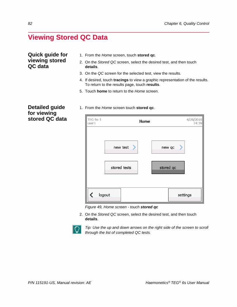
82 Chapter 6, Quality Control
Viewing Stored QC Data
Quick guide for viewing stored QC data
1. From the Home screen, touch stored qc.
2. On the Stored QC screen, select the desired test, and then touch details.
3. On the QC screen for the selected test, view the results.
4. If desired, touch tracings to view a graphic representation of the results. To return to the results page, touch results.
5. Touch home to return to the Home screen.
Detailed guide for viewing stored QC data
1. From the Home screen touch stored qc.
Figure 49, Home screen - touch stored qc
2. On the Stored QC screen, select the desired test, and then touch details.
Tip: Use the up and down arrows on the right side of the screen to scroll through the list of completed QC tests.
P/N 115191-US, Manual revision: AE Haemonetics® TEG® 6s User Manual
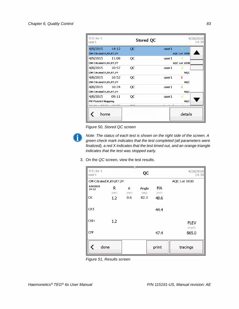
Chapter 6, Quality Control 83
Figure 50, Stored QC screen
Note: The status of each test is shown on the right side of the screen. A green check mark indicates that the test completed (all parameters were finalized), a red X indicates that the test timed out, and an orange triangle indicates that the test was stopped early.
3. On the QC screen, view the test results.
Figure 51, Results screen
Haemonetics® TEG® 6s User Manual P/N 115191-US, Manual revision: AE
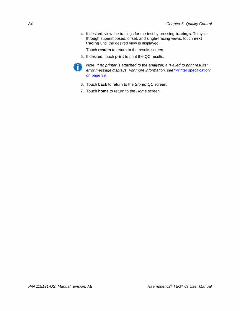
84 Chapter 6, Quality Control
4. If desired, view the tracings for the test by pressing tracings. To cycle through superimposed, offset, and single-tracing views, touch next tracing until the desired view is displayed.
Touch results to return to the results screen.
5. If desired, touch print to print the QC results.
Note: If no printer is attached to the analyzer, a “Failed to print results” error message displays. For more information, see “Printer specification” on page 99.
6. Touch back to return to the Stored QC screen.
7. Touch home to return to the Home screen.
P/N 115191-US, Manual revision: AE Haemonetics® TEG® 6s User Manual
Chapter 7
Troubleshooting and Maintenance
Errors and Alerts . . . . . . . . . . . . . . . . . . . . . . . . . . . . . . . . . . . . . . . . . . . . . .86Error messages . . . . . . . . . . . . . . . . . . . . . . . . . . . . . . . . . . . . . . . . . . . .86Warning messages . . . . . . . . . . . . . . . . . . . . . . . . . . . . . . . . . . . . . . . . .87Critical alert messages . . . . . . . . . . . . . . . . . . . . . . . . . . . . . . . . . . . . . .87Error message table . . . . . . . . . . . . . . . . . . . . . . . . . . . . . . . . . . . . . . . .88
Cleaning and Disinfecting the Analyzer . . . . . . . . . . . . . . . . . . . . . . . . . . . .94Clean the filter . . . . . . . . . . . . . . . . . . . . . . . . . . . . . . . . . . . . . . . . . . . . .95
Haemonetics® TEG® 6s User Manual P/N 115191-US, Manual revision: AE
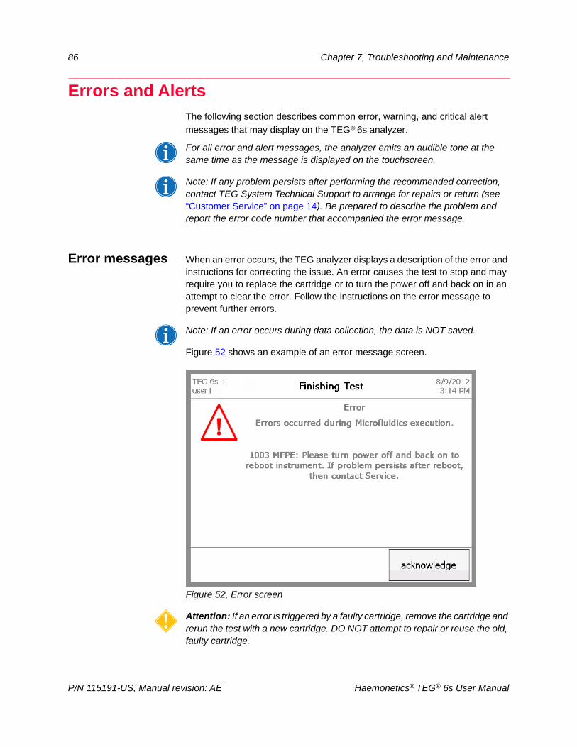
86 Chapter 7, Troubleshooting and Maintenance
Errors and AlertsThe following section describes common error, warning, and critical alert
messages that may display on the TEG® 6s analyzer.
For all error and alert messages, the analyzer emits an audible tone at the same time as the message is displayed on the touchscreen.
Note: If any problem persists after performing the recommended correction, contact TEG System Technical Support to arrange for repairs or return (see “Customer Service” on page 14). Be prepared to describe the problem and report the error code number that accompanied the error message.
Error messages When an error occurs, the TEG analyzer displays a description of the error and instructions for correcting the issue. An error causes the test to stop and may require you to replace the cartridge or to turn the power off and back on in an attempt to clear the error. Follow the instructions on the error message to prevent further errors.
Note: If an error occurs during data collection, the data is NOT saved.
Figure 52 shows an example of an error message screen.
Figure 52, Error screen
Attention: If an error is triggered by a faulty cartridge, remove the cartridge and rerun the test with a new cartridge. DO NOT attempt to repair or reuse the old, faulty cartridge.
P/N 115191-US, Manual revision: AE Haemonetics® TEG® 6s User Manual
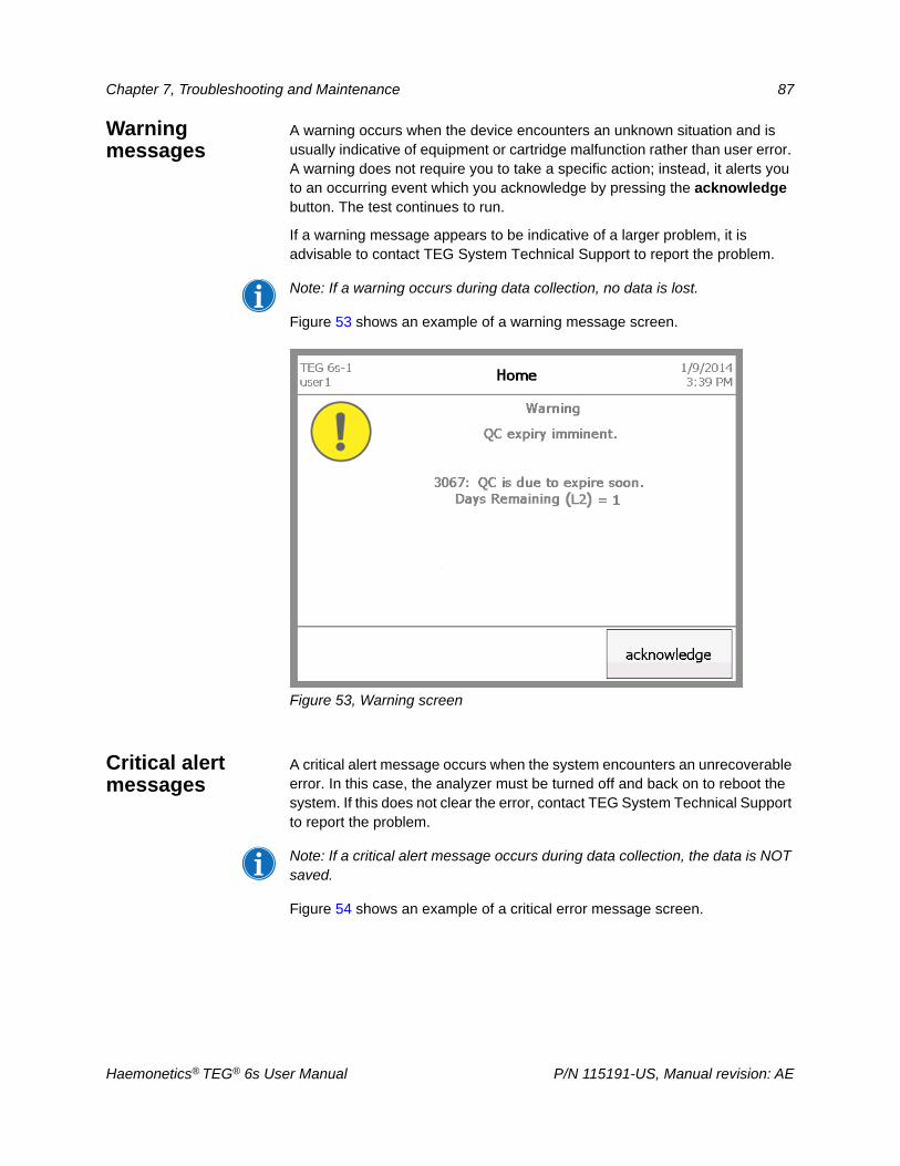
Chapter 7, Troubleshooting and Maintenance 87
Warning messages
A warning occurs when the device encounters an unknown situation and is usually indicative of equipment or cartridge malfunction rather than user error. A warning does not require you to take a specific action; instead, it alerts you to an occurring event which you acknowledge by pressing the acknowledge button. The test continues to run.
If a warning message appears to be indicative of a larger problem, it is advisable to contact TEG System Technical Support to report the problem.
Note: If a warning occurs during data collection, no data is lost.
Figure 53 shows an example of a warning message screen.
Figure 53, Warning screen
Critical alert messages
A critical alert message occurs when the system encounters an unrecoverable error. In this case, the analyzer must be turned off and back on to reboot the system. If this does not clear the error, contact TEG System Technical Support to report the problem.
Note: If a critical alert message occurs during data collection, the data is NOT saved.
Figure 54 shows an example of a critical error message screen.
Haemonetics® TEG® 6s User Manual P/N 115191-US, Manual revision: AE
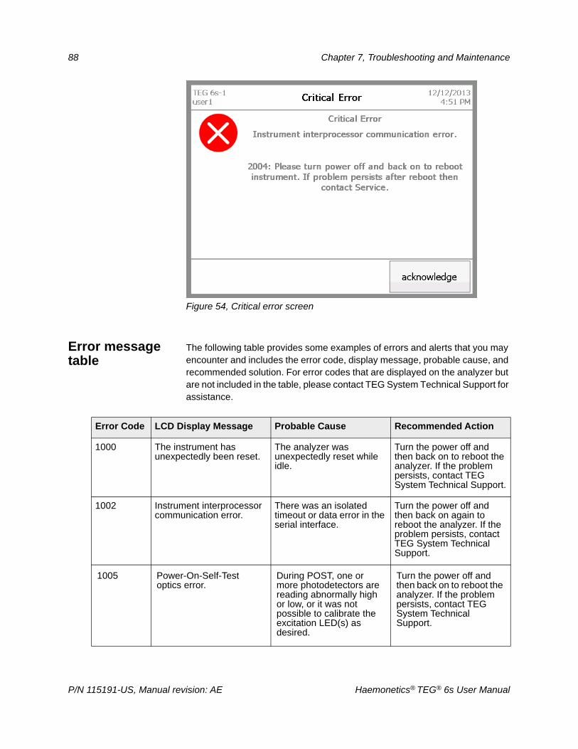
88 Chapter 7, Troubleshooting and Maintenance
Figure 54, Critical error screen
Error message table
The following table provides some examples of errors and alerts that you may encounter and includes the error code, display message, probable cause, and recommended solution. For error codes that are displayed on the analyzer but are not included in the table, please contact TEG System Technical Support for assistance.
Error Code LCD Display Message Probable Cause Recommended Action
1000 The instrument has unexpectedly been reset.
The analyzer was unexpectedly reset while idle.
Turn the power off and then back on to reboot the analyzer. If the problem persists, contact TEG System Technical Support.
1002 Instrument interprocessor communication error.
There was an isolated timeout or data error in the serial interface.
Turn the power off and then back on again to reboot the analyzer. If the problem persists, contact TEG System Technical Support.
1005 Power-On-Self-Test optics error.
During POST, one or more photodetectors are reading abnormally high or low, or it was not possible to calibrate the excitation LED(s) as desired.
Turn the power off and then back on to reboot the analyzer. If the problem persists, contact TEG System Technical Support.
P/N 115191-US, Manual revision: AE Haemonetics® TEG® 6s User Manual
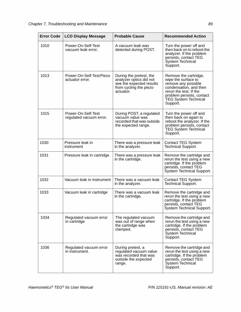
Chapter 7, Troubleshooting and Maintenance 89
1010 Power-On-Self-Test vacuum leak error.
A vacuum leak was detected during POST.
Turn the power off and then back on to reboot the analyzer. If the problem persists, contact TEG System Technical Support.
1013 Power-On-Self-Test Piezo actuator error.
During the pretest, the analyzer optics did not see the expected results from cycling the piezo actuator.
Remove the cartridge, wipe the surface to remove any possible condensation, and then rerun the test. If the problem persists, contact TEG System Technical Support.
1015 Power-On-Self-Test regulated vacuum error.
During POST, a regulated vacuum value was recorded that was outside the expected range.
Turn the power off and then back on again to reboot the analyzer. If the problem persists, contact TEG System Technical Support.
1030 Pressure leak in instrument
There was a pressure leak in the analyzer.
Contact TEG System Technical Support.
1031 Pressure leak in cartridge There was a pressure leak in the cartridge.
Remove the cartridge and rerun the test using a new cartridge. If the problem persists, contact TEG System Technical Support.
1032 Vacuum leak in instrument There was a vacuum leak in the analyzer.
Contact TEG System Technical Support.
1033 Vacuum leak in cartridge There was a vacuum leak in the cartridge.
Remove the cartridge and rerun the test using a new cartridge. If the problem persists, contact TEG System Technical Support.
1034 Regulated vacuum error in cartridge
The regulated vacuum was out of range when the cartridge was clamped.
Remove the cartridge and rerun the test using a new cartridge. If the problem persists, contact TEG System Technical Support.
1036 Regulated vacuum error in instrument.
During pretest, a regulated vacuum value was recorded that was outside the expected range.
Remove the cartridge and rerun the test using a new cartridge. If the problem persists, contact TEG System Technical Support.
Error Code LCD Display Message Probable Cause Recommended Action
Haemonetics® TEG® 6s User Manual P/N 115191-US, Manual revision: AE
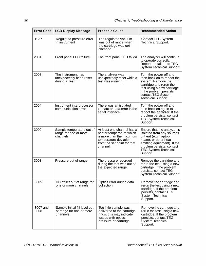
90 Chapter 7, Troubleshooting and Maintenance
1037 Regulated pressure error in instrument
The regulated vacuum was out of range when the cartridge was not clamped.
Contact TEG System Technical Support.
2001 Front panel LED failure The front panel LED failed. The analyzer will continue to operate correctly. Report the failure to TEG System Technical Support.
2003 The instrument has unexpectedly been reset during a Test
The analyzer was unexpectedly reset while a test was running.
Turn the power off and then back on to reboot the system. Remove the cartridge and rerun the test using a new cartridge. If the problem persists, contact TEG System Technical Support.
2004 Instrument interprocessor communication error.
There was an isolated timeout or data error in the serial interface.
Turn the power off and then back on again to reboot the analyzer. If the problem persists, contact TEG System Technical Support.
3000 Sample temperature out of range for one or more channels
At least one channel has a heater temperature which is more than the maximum temperature deviation from the set point for that channel.
Ensure that the analyzer is isolated from any sources of heat (e.g., laptop, heater, or other heat-emitting equipment). If the problem persists, contact TEG System Technical Support.
3003 Pressure out of range. The pressure recorded during the test was out of the expected range.
Remove the cartridge and rerun the test using a new cartridge. If the problem persists, contact TEG System Technical Support.
3005 DC offset out of range for one or more channels.
Optics error during data collection
Remove the cartridge and rerun the test using a new cartridge. If the problem persists, contact TEG System Technical Support.
3007 and 3008
Sample initial fill level out of range for one or more channels.
Too little sample was delivered to the cartridge rings; this may indicate issues with optics, pressure or cartridge
Remove the cartridge and rerun the test using a new cartridge. If the problem persists, contact TEG System Technical Support.
Error Code LCD Display Message Probable Cause Recommended Action
P/N 115191-US, Manual revision: AE Haemonetics® TEG® 6s User Manual
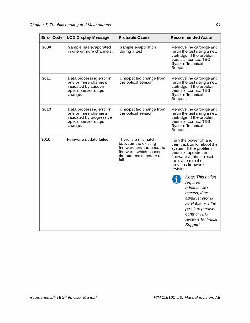
Chapter 7, Troubleshooting and Maintenance 91
3009 Sample has evaporated in one or more channels.
Sample evaporation during a test
Remove the cartridge and rerun the test using a new cartridge. If the problem persists, contact TEG System Technical Support.
3011 Data processing error in one or more channels, indicated by sudden optical sensor output change.
Unexpected change from the optical sensor.
Remove the cartridge and rerun the test using a new cartridge. If the problem persists, contact TEG System Technical Support.
3013 Data processing error in one or more channels, indicated by progressive optical sensor output change.
Unexpected change from the optical sensor.
Remove the cartridge and rerun the test using a new cartridge. If the problem persists, contact TEG System Technical Support.
3019 Firmware update failed There is a mismatch between the existing firmware and the updated firmware, which causes the automatic update to fail.
Turn the power off and then back on to reboot the system. If the problem persists, update the firmware again or reset the system to the previous firmware revision.
Note: This action requires administrator access; if no administrator is available or if the problem persists, contact TEG System Technical Support.
Error Code LCD Display Message Probable Cause Recommended Action
Haemonetics® TEG® 6s User Manual P/N 115191-US, Manual revision: AE
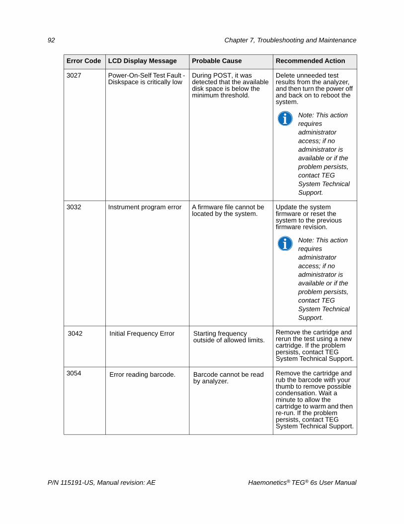
92 Chapter 7, Troubleshooting and Maintenance
3027 Power-On-Self Test Fault - Diskspace is critically low
During POST, it was detected that the available disk space is below the minimum threshold.
Delete unneeded test results from the analyzer, and then turn the power off and back on to reboot the system.
Note: This action requires administrator access; if no administrator is available or if the problem persists, contact TEG System Technical Support.
3032 Instrument program error A firmware file cannot be located by the system.
Update the system firmware or reset the system to the previous firmware revision.
Note: This action requires administrator access; if no administrator is available or if the problem persists, contact TEG System Technical Support.
3042 Initial Frequency Error Starting frequency outside of allowed limits.
Remove the cartridge and rerun the test using a new cartridge. If the problem persists, contact TEG System Technical Support.
3054 Error reading barcode. Barcode cannot be read by analyzer.
Remove the cartridge and rub the barcode with your thumb to remove possible condensation. Wait a minute to allow the cartridge to warm and then re-run. If the problem persists, contact TEG System Technical Support.
Error Code LCD Display Message Probable Cause Recommended Action
P/N 115191-US, Manual revision: AE Haemonetics® TEG® 6s User Manual
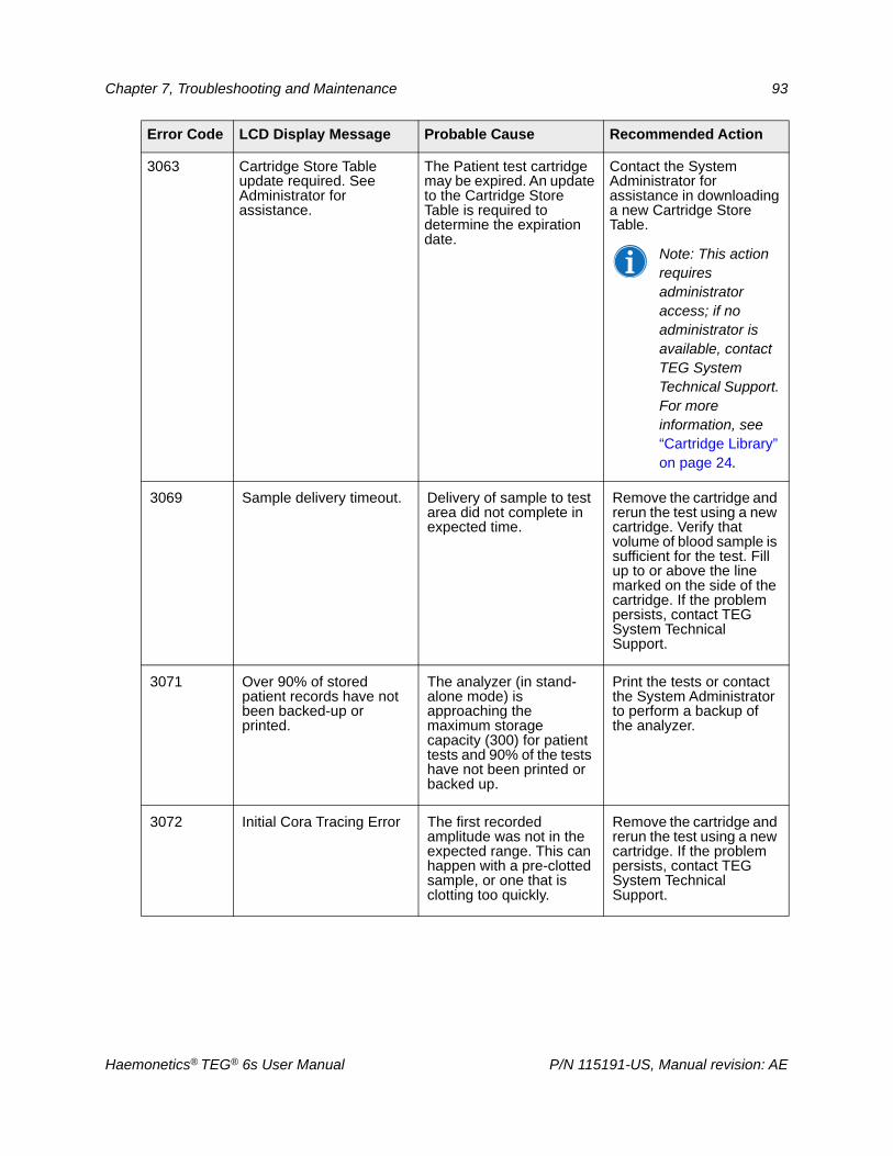
Chapter 7, Troubleshooting and Maintenance 93
3063 Cartridge Store Table update required. See Administrator for assistance.
The Patient test cartridge may be expired. An update to the Cartridge Store Table is required to determine the expiration date.
Contact the System Administrator for assistance in downloading a new Cartridge Store Table.
Note: This action requires administrator access; if no administrator is available, contact TEG System Technical Support. For more information, see “Cartridge Library” on page 24.
3069 Sample delivery timeout. Delivery of sample to test area did not complete in expected time.
Remove the cartridge and rerun the test using a new cartridge. Verify that volume of blood sample is sufficient for the test. Fill up to or above the line marked on the side of the cartridge. If the problem persists, contact TEG System Technical Support.
3071 Over 90% of stored patient records have not been backed-up or printed.
The analyzer (in stand-alone mode) is approaching the maximum storage capacity (300) for patient tests and 90% of the tests have not been printed or backed up.
Print the tests or contact the System Administrator to perform a backup of the analyzer.
3072 Initial Cora Tracing Error The first recorded amplitude was not in the expected range. This can happen with a pre-clotted sample, or one that is clotting too quickly.
Remove the cartridge and rerun the test using a new cartridge. If the problem persists, contact TEG System Technical Support.
Error Code LCD Display Message Probable Cause Recommended Action
Haemonetics® TEG® 6s User Manual P/N 115191-US, Manual revision: AE
94 Chapter 7, Troubleshooting and Maintenance
Cleaning and Disinfecting the AnalyzerThe surfaces of the TEG analyzer must be wiped down and disinfected weekly, or more frequently, as needed. Use laboratory medical disinfecting procedures to prevent contamination of the analyzer and limit potential exposure of bloodborne pathogens to operating personnel.
Products containing a 70-95% isopropyl alcohol solution are recommended,
and commonly-used germicidal disposable wipes (PDI Super Sani-Cloth® or equivalent) are effective and will not cause damage to the TEG analyzer when used according to manufacturer’s instructions.
The TEG analyzer must also be cleaned and disinfected prior to return shipment if servicing is necessary. For further information, see “Product return guidelines” on page 14.
All materials used for disinfecting should be disposed of in the proper biohazard waste receptacles.
Attention:
Turn off the analyzer and unplug it from the wall before cleaning.
Do not steam-sterilize or autoclave the analyzer or any cartridge.
Do not immerse the analyzer or cartridge in any solution.
Do not clean the analyzer or cartridge with acetone or any other plastic solvent or abrasive cleaner.
Note: If there is any doubt about the compatibility of decontamination or cleaning agents with parts of the device or with material contained within it, the Administrator or Laboratory Supervisor may consult with Haemonetics or an authorized distributor regarding such use.
Materials needed
Disposable gloves
70-95% isopropyl alcohol plus 2” x 2” gauze pads OR germicidal disposable wipes
Warm running water
Clean the analyzer
To clean and disinfect the surfaces of the analyzer:
1. Turn off the analyzer and unplug it from the wall.
2. Put on disposable gloves.
3. Using gauze pads soaked in isopropyl alcohol or germicidal disposable wipes, thoroughly clean all external surfaces of the TEG analyzer, including the touch screen.
Attention: Avoid getting liquid into the cartridge slot at the front of the analyzer or into connectors on the rear panel.
P/N 115191-US, Manual revision: AE Haemonetics® TEG® 6s User Manual
Chapter 7, Troubleshooting and Maintenance 95
Clean the filter The TEG analyzer has a filter assembly mounted at the rear of the unit to filter air as it is drawn into the unit by the fan. This filter should be cleaned or replaced during each scheduled preventive maintenance (PM) procedure. If a temperature error occurs before a scheduled PM, clean the filter using the following instructions.
To clean the filter:
1. Grasp the edges of the filter cover and pull to remove it.
2. Remove the filter from the cover.
3. Rinse the filter under warm running water until it is clean. Do not use soap or any cleaning solution.
4. Squeeze out any excess water, place on a clean cloth, and allow to dry completely.
5. Ensure the filter is 100% dry, and then reinsert the filter into the filter cover.
6. Press the filter cover back onto the analyzer.
7. Record the date of maintenance.
Haemonetics® TEG® 6s User Manual P/N 115191-US, Manual revision: AE

Chapter 8
Specifications and Performance Characteristics
Specifications . . . . . . . . . . . . . . . . . . . . . . . . . . . . . . . . . . . . . . . . . . . . . . . .98Physical specifications. . . . . . . . . . . . . . . . . . . . . . . . . . . . . . . . . . . . . . .98Environmental specifications . . . . . . . . . . . . . . . . . . . . . . . . . . . . . . . . . .98Electrical specifications . . . . . . . . . . . . . . . . . . . . . . . . . . . . . . . . . . . . . .98Printer specification . . . . . . . . . . . . . . . . . . . . . . . . . . . . . . . . . . . . . . . . .99Analytical Measurement Ranges. . . . . . . . . . . . . . . . . . . . . . . . . . . . . . .99
Performance Characteristics . . . . . . . . . . . . . . . . . . . . . . . . . . . . . . . . . . .101FCC Compliance . . . . . . . . . . . . . . . . . . . . . . . . . . . . . . . . . . . . . . . . . .101Warranty . . . . . . . . . . . . . . . . . . . . . . . . . . . . . . . . . . . . . . . . . . . . . . . .101
Haemonetics® TEG® 6s User Manual P/N 115191-US, Manual revision: AE
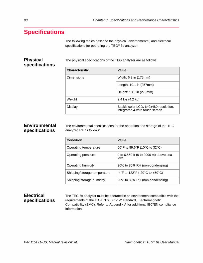
98 Chapter 8, Specifications and Performance Characteristics
SpecificationsThe following tables describe the physical, environmental, and electrical
specifications for operating the TEG® 6s analyzer.
Physical specifications
The physical specifications of the TEG analyzer are as follows:
Environmental specifications
The environmental specifications for the operation and storage of the TEG analyzer are as follows:
Electrical specifications
The TEG 6s analyzer must be operated in an environment compatible with the requirements of the IEC/EN 60601-1-2 standard, Electromagnetic Compatibility (EMC). Refer to Appendix A for additional IEC/EN compliance information.
Characteristic Value
Dimensions Width: 6.9 in (175mm)
Length: 10.1 in (257mm)
Height: 10.6 in (270mm)
Weight 9.4 lbs (4.2 kg)
Display Backlit color LCD, 640x480 resolution, integrated 4-wire touch screen
Condition Value
Operating temperature 50°F to 89.6°F (10°C to 32°C)
Operating pressure 0 to 6,560 ft (0 to 2000 m) above sea level
Operating humidity 20% to 80% RH (non-condensing)
Shipping/storage temperature -4°F to 122°F (-20°C to +50°C)
Shipping/storage humidity 20% to 80% RH (non-condensing)
P/N 115191-US, Manual revision: AE Haemonetics® TEG® 6s User Manual
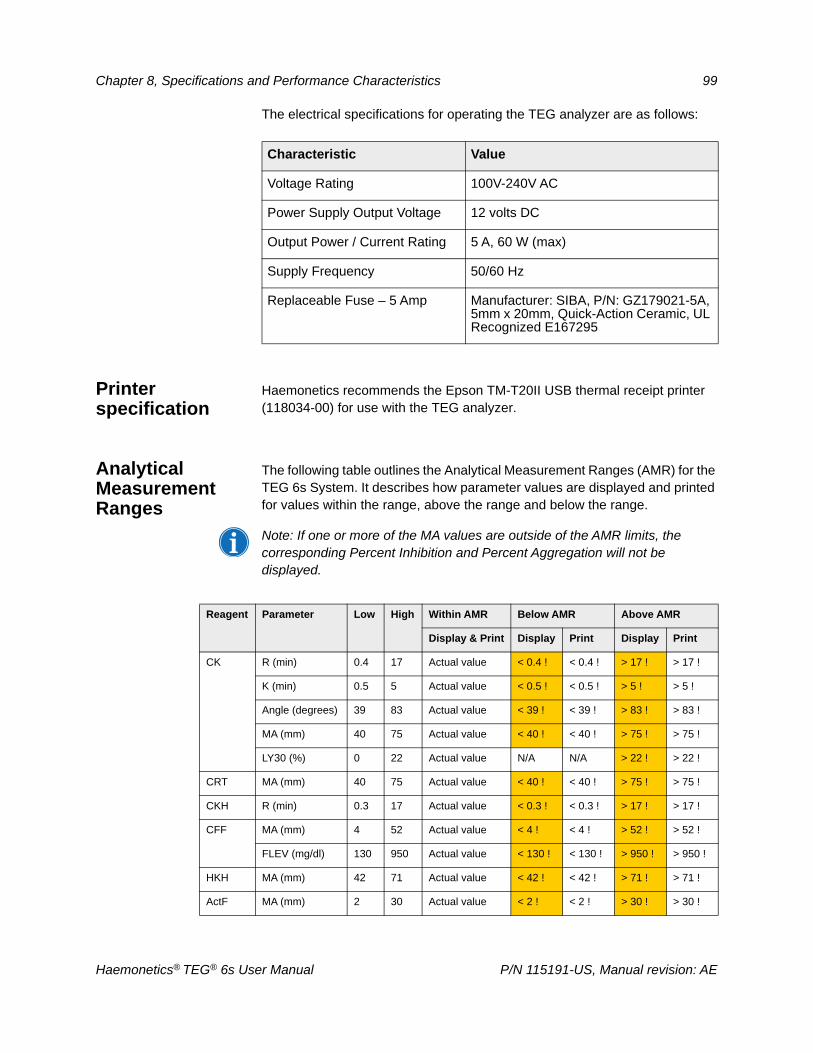
Chapter 8, Specifications and Performance Characteristics 99
The electrical specifications for operating the TEG analyzer are as follows:
Printer specification
Haemonetics recommends the Epson TM-T20II USB thermal receipt printer (118034-00) for use with the TEG analyzer.
Analytical Measurement Ranges
The following table outlines the Analytical Measurement Ranges (AMR) for the TEG 6s System. It describes how parameter values are displayed and printed for values within the range, above the range and below the range.
Note: If one or more of the MA values are outside of the AMR limits, the corresponding Percent Inhibition and Percent Aggregation will not be displayed.
Characteristic Value
Voltage Rating 100V-240V AC
Power Supply Output Voltage 12 volts DC
Output Power / Current Rating 5 A, 60 W (max)
Supply Frequency 50/60 Hz
Replaceable Fuse – 5 Amp Manufacturer: SIBA, P/N: GZ179021-5A, 5mm x 20mm, Quick-Action Ceramic, UL Recognized E167295
Reagent Parameter Low High Within AMR Below AMR Above AMR
Display & Print Display Print Display Print
CK R (min) 0.4 17 Actual value < 0.4 ! < 0.4 ! > 17 ! > 17 !
K (min) 0.5 5 Actual value < 0.5 ! < 0.5 ! > 5 ! > 5 !
Angle (degrees) 39 83 Actual value < 39 ! < 39 ! > 83 ! > 83 !
MA (mm) 40 75 Actual value < 40 ! < 40 ! > 75 ! > 75 !
LY30 (%) 0 22 Actual value N/A N/A > 22 ! > 22 !
CRT MA (mm) 40 75 Actual value < 40 ! < 40 ! > 75 ! > 75 !
CKH R (min) 0.3 17 Actual value < 0.3 ! < 0.3 ! > 17 ! > 17 !
CFF MA (mm) 4 52 Actual value < 4 ! < 4 ! > 52 ! > 52 !
FLEV (mg/dl) 130 950 Actual value < 130 ! < 130 ! > 950 ! > 950 !
HKH MA (mm) 42 71 Actual value < 42 ! < 42 ! > 71 ! > 71 !
ActF MA (mm) 2 30 Actual value < 2 ! < 2 ! > 30 ! > 30 !
Haemonetics® TEG® 6s User Manual P/N 115191-US, Manual revision: AE
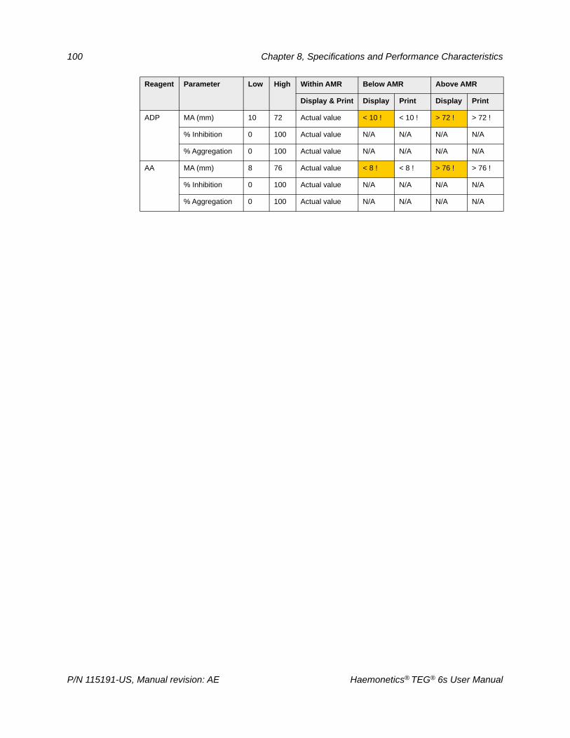
100 Chapter 8, Specifications and Performance Characteristics
ADP MA (mm) 10 72 Actual value < 10 ! < 10 ! > 72 ! > 72 !
% Inhibition 0 100 Actual value N/A N/A N/A N/A
% Aggregation 0 100 Actual value N/A N/A N/A N/A
AA MA (mm) 8 76 Actual value < 8 ! < 8 ! > 76 ! > 76 !
% Inhibition 0 100 Actual value N/A N/A N/A N/A
% Aggregation 0 100 Actual value N/A N/A N/A N/A
Reagent Parameter Low High Within AMR Below AMR Above AMR
Display & Print Display Print Display Print
P/N 115191-US, Manual revision: AE Haemonetics® TEG® 6s User Manual
Chapter 8, Specifications and Performance Characteristics 101
Performance Characteristics
FCC Compliance
This equipment has been tested and found to comply with the limits for a Class A digital device, pursuant to part 15 of the FCC rules. These limits are designed to provide reasonable protection against harmful interference when the equipment is operated in a commercial environment. This equipment generates, uses and can radiate radio frequency energy and, if not installed and used in accordance with the instruction manual, may cause harmful interference to radio communications. Operation of this equipment in a residential area is likely to cause harmful interference in which case users will be required to correct the interference at their own expense.
Attention: Any changes or modifications not expressly approved by Haemonetics could void the user’s authority to operate this equipment.
Note: “Harmful interference” is defined by the FCC as follows: Any emission, radiation or induction that endangers the functioning of a radio navigation service or of other safety services or seriously degrades, obstructs or repeatedly interrupts a radiocommunications service operating in accordance with FCC rules.
Warranty Haemonetics warrants its manufactured products (excluding disposable or consumable supplies) to be free from defects in materials or workmanship for one year from the original date of purchase subject to these terms and conditions. Returns will not be accepted without authorization from a Haemonetics Representative. Products must show no evidence of improper handling or operation, including unauthorized repairs.
At its discretion, Haemonetics may repair or replace defective products covered by this warranty. Even if Haemonetics cannot repair or replace, its entire liability shall in no event exceed the purchase price. Haemonetics expressly disclaims all other warranties, whether express, implied, or statutory, including the warranty of merchantability and fitness of use. In no event will Haemonetics be liable for consequential, incidental, or special damages arising out of the use of its products.
Haemonetics® TEG® 6s User Manual P/N 115191-US, Manual revision: AE

Appendix A A
IEC/EN 60601-1-2 Standard Requirements
Operation Precautions . . . . . . . . . . . . . . . . . . . . . . . . . . . . . . . . . . . . . . . .104Power supply . . . . . . . . . . . . . . . . . . . . . . . . . . . . . . . . . . . . . . . . . . . . .104Electro-magnetic immunity . . . . . . . . . . . . . . . . . . . . . . . . . . . . . . . . . .104
Electromagnetic Compatibility . . . . . . . . . . . . . . . . . . . . . . . . . . . . . . . . . .105
Haemonetics® TEG® 6s User Manual P/N 115191-US, Manual Revision: AE
104 Appendix A, IEC/EN 60601-1-2 Standard Requirements
Operation Precautions
Power supply Note: The device meets the requirements of the IEC/EN 60601-1-2 Standard, Electromagnetic Compatibility (EMC).
A power cord is supplied with the device. Do not replace the power cord with a substitute. If necessary, contact TEG System Technical Support for a replacement. Always ensure the power cord is connected to an appropriately grounded power source.
Warning: Ground continuity can only be achieved when the equipment is connected to a properly grounded outlet.
Attention: Do not use non-approved accessories and cables. Any accessories and cables not approved by Haemonetics, used in conjunction with the device, may increase hazards and influence compatibility with EMC requirements.
Electro-magnetic immunity
Mobile radio frequency (RF) communication equipment not approved by Haemonetics and portable communication equipment can affect the system.
Attention: MR Unsafe. The device should not be used near active high-frequency surgical equipment or in the RF shielded room of magnetic resonance imaging (MRI) equipment, where the intensity of electromagnetic disturbances is high.
Attention: Do not use radio-frequency identification (RFID) readers near the device.
Attention: Do not place the device and accessories directly adjacent to, or on top of other equipment, unless specifically approved by Haemonetics.
To avoid electrostatic discharge, floors should be wood, concrete or ceramic tile. If floors are covered with synthetic material, the relative humidity is recommended to be at least 30%.
Attention: If the relative humidity in the operating environment is below 30%, precautions should be taken to prevent electrostatic discharge such as touching a large metal object before handling the analyzer or a disposable cartridge.
P/N 115191-US, Manual Revision: AE Haemonetics® TEG® 6s User Manual
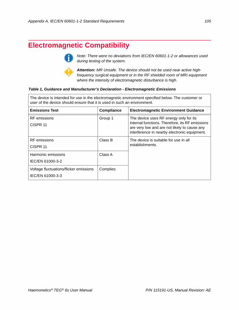
Appendix A, IEC/EN 60601-1-2 Standard Requirements 105
Electromagnetic CompatibilityNote: There were no deviations from IEC/EN 60601-1-2 or allowances used during testing of the system.
Attention: MR Unsafe. The device should not be used near active high-frequency surgical equipment or in the RF shielded room of MRI equipment where the intensity of electromagnetic disturbance is high.
Table 1, Guidance and Manufacturer’s Declaration - Electromagnetic Emissions
The device is intended for use in the electromagnetic environment specified below. The customer or user of the device should ensure that it is used in such an environment.
Emissions Test Compliance Electromagnetic Environment Guidance
RF emissions
CISPR 11
Group 1 The device uses RF energy only for its internal functions. Therefore, its RF emissions are very low and are not likely to cause any interference in nearby electronic equipment.
RF emissions
CISPR 11
Class B The device is suitable for use in all establishments.
Harmonic emissions
IEC/EN 61000-3-2
Class A
Voltage fluctuations/flicker emissions
IEC/EN 61000-3-3
Complies
Haemonetics® TEG® 6s User Manual P/N 115191-US, Manual Revision: AE
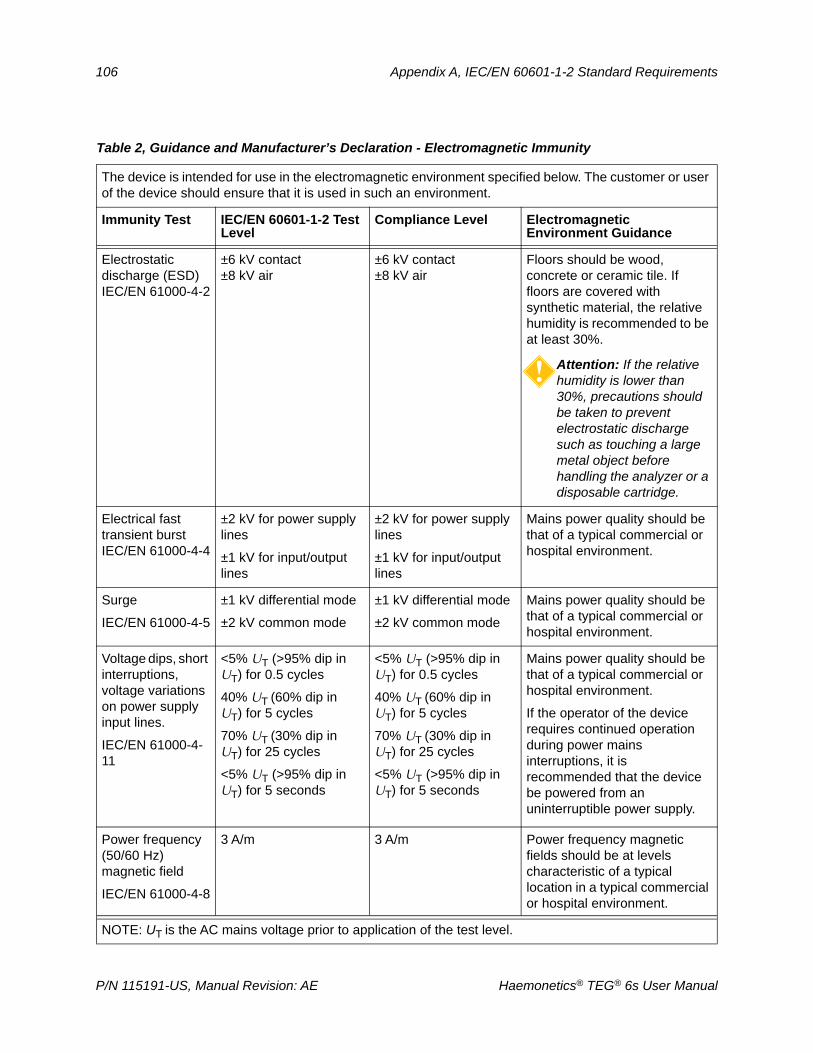
106 Appendix A, IEC/EN 60601-1-2 Standard Requirements
Table 2, Guidance and Manufacturer’s Declaration - Electromagnetic Immunity
The device is intended for use in the electromagnetic environment specified below. The customer or user of the device should ensure that it is used in such an environment.
Immunity Test IEC/EN 60601-1-2 Test Level
Compliance Level Electromagnetic Environment Guidance
Electrostatic discharge (ESD) IEC/EN 61000-4-2
±6 kV contact ±8 kV air
±6 kV contact±8 kV air
Floors should be wood, concrete or ceramic tile. If floors are covered with synthetic material, the relative humidity is recommended to be at least 30%.
Attention: If the relative humidity is lower than 30%, precautions should be taken to prevent electrostatic discharge such as touching a large metal object before handling the analyzer or a disposable cartridge.
Electrical fast transient burst IEC/EN 61000-4-4
±2 kV for power supply lines
±1 kV for input/output lines
±2 kV for power supply lines
±1 kV for input/output lines
Mains power quality should be that of a typical commercial or hospital environment.
Surge
IEC/EN 61000-4-5
±1 kV differential mode
±2 kV common mode
±1 kV differential mode
±2 kV common mode
Mains power quality should be that of a typical commercial or hospital environment.
Voltage dips, short interruptions, voltage variations on power supply input lines.
IEC/EN 61000-4-11
<5% UT (>95% dip in UT) for 0.5 cycles
40% UT (60% dip inUT) for 5 cycles
70% UT (30% dip inUT) for 25 cycles
<5% UT (>95% dip in UT) for 5 seconds
<5% UT (>95% dip in UT) for 0.5 cycles
40% UT (60% dip inUT) for 5 cycles
70% UT (30% dip inUT) for 25 cycles
<5% UT (>95% dip in UT) for 5 seconds
Mains power quality should be that of a typical commercial or hospital environment.
If the operator of the device requires continued operation during power mains interruptions, it is recommended that the device be powered from an uninterruptible power supply.
Power frequency (50/60 Hz) magnetic field
IEC/EN 61000-4-8
3 A/m 3 A/m Power frequency magnetic fields should be at levels characteristic of a typical location in a typical commercial or hospital environment.
NOTE: UT is the AC mains voltage prior to application of the test level.
P/N 115191-US, Manual Revision: AE Haemonetics® TEG® 6s User Manual
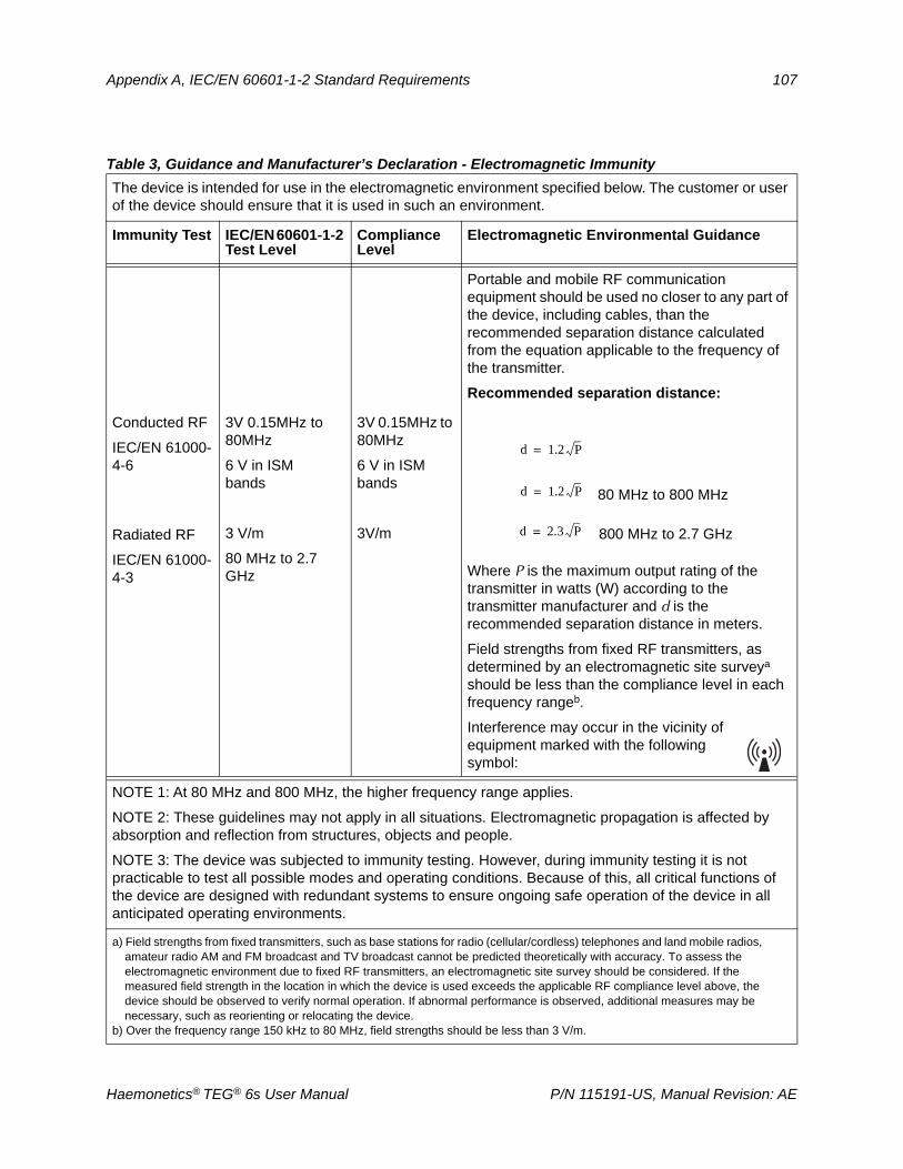
Appendix A, IEC/EN 60601-1-2 Standard Requirements 107
Table 3, Guidance and Manufacturer’s Declaration - Electromagnetic Immunity
The device is intended for use in the electromagnetic environment specified below. The customer or user of the device should ensure that it is used in such an environment.
Immunity Test IEC/EN 60601-1-2 Test Level
Compliance Level
Electromagnetic Environmental Guidance
Portable and mobile RF communication equipment should be used no closer to any part of the device, including cables, than the recommended separation distance calculated from the equation applicable to the frequency of the transmitter.
Recommended separation distance:
Conducted RF
IEC/EN 61000-4-6
Radiated RF
IEC/EN 61000-4-3
3V 0.15MHz to 80MHz
6 V in ISM bands
3 V/m
80 MHz to 2.7 GHz
3V 0.15MHz to 80MHz
6 V in ISM bands
3V/m
Where P is the maximum output rating of the transmitter in watts (W) according to the transmitter manufacturer and d is the recommended separation distance in meters.
Field strengths from fixed RF transmitters, as determined by an electromagnetic site surveya should be less than the compliance level in each frequency rangeb.
Interference may occur in the vicinity of equipment marked with the following symbol:
NOTE 1: At 80 MHz and 800 MHz, the higher frequency range applies.
NOTE 2: These guidelines may not apply in all situations. Electromagnetic propagation is affected by absorption and reflection from structures, objects and people.
NOTE 3: The device was subjected to immunity testing. However, during immunity testing it is not practicable to test all possible modes and operating conditions. Because of this, all critical functions of the device are designed with redundant systems to ensure ongoing safe operation of the device in all anticipated operating environments.
a) Field strengths from fixed transmitters, such as base stations for radio (cellular/cordless) telephones and land mobile radios, amateur radio AM and FM broadcast and TV broadcast cannot be predicted theoretically with accuracy. To assess the electromagnetic environment due to fixed RF transmitters, an electromagnetic site survey should be considered. If the measured field strength in the location in which the device is used exceeds the applicable RF compliance level above, the device should be observed to verify normal operation. If abnormal performance is observed, additional measures may be necessary, such as reorienting or relocating the device.
b) Over the frequency range 150 kHz to 80 MHz, field strengths should be less than 3 V/m.
d 1.2 P=
d 1.2 P= 80 MHz to 800 MHz
d 2.3 P= 800 MHz to 2.7 GHz
Haemonetics® TEG® 6s User Manual P/N 115191-US, Manual Revision: AE
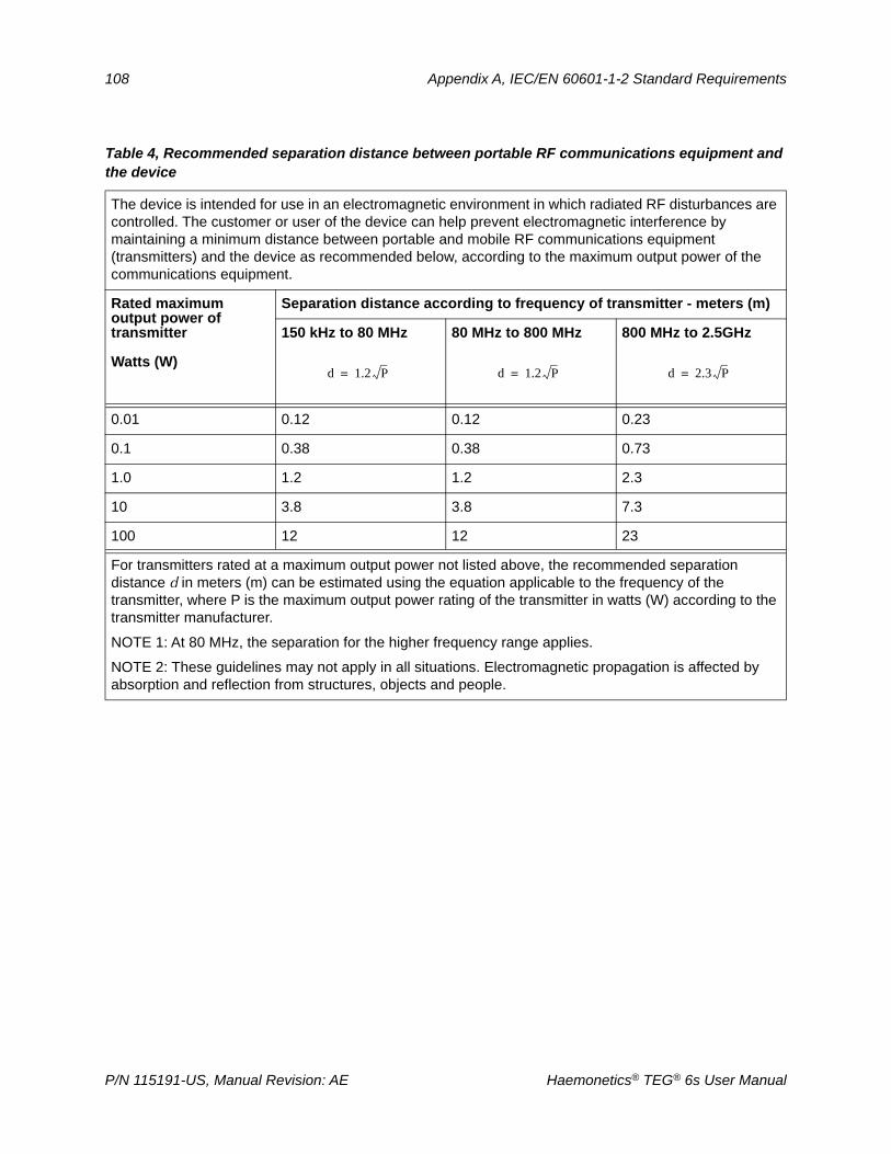
108 Appendix A, IEC/EN 60601-1-2 Standard Requirements
Table 4, Recommended separation distance between portable RF communications equipment and the device
The device is intended for use in an electromagnetic environment in which radiated RF disturbances are controlled. The customer or user of the device can help prevent electromagnetic interference by maintaining a minimum distance between portable and mobile RF communications equipment (transmitters) and the device as recommended below, according to the maximum output power of the communications equipment.
Rated maximum output power of transmitter
Watts (W)
Separation distance according to frequency of transmitter - meters (m)
150 kHz to 80 MHz 80 MHz to 800 MHz 800 MHz to 2.5GHz
0.01 0.12 0.12 0.23
0.1 0.38 0.38 0.73
1.0 1.2 1.2 2.3
10 3.8 3.8 7.3
100 12 12 23
For transmitters rated at a maximum output power not listed above, the recommended separation distance d in meters (m) can be estimated using the equation applicable to the frequency of the transmitter, where P is the maximum output power rating of the transmitter in watts (W) according to the transmitter manufacturer.
NOTE 1: At 80 MHz, the separation for the higher frequency range applies.
NOTE 2: These guidelines may not apply in all situations. Electromagnetic propagation is affected by absorption and reflection from structures, objects and people.
d 1.2 P= d 1.2 P= d 2.3 P=
P/N 115191-US, Manual Revision: AE Haemonetics® TEG® 6s User Manual