Embed Size (px)
Citation preview
User Manual – High Speed Counter
Copyright © Hitachi Europe GmbH 2015. All rights reserved.
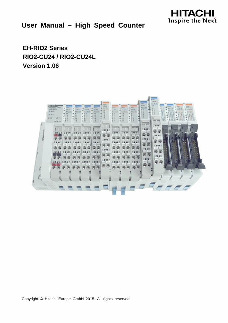
EH-RIO2 Series RIO2-CU24 / RIO2-CU24L Version 1.06

User Manual – High Speed Counter
DOCUMENT CHANGE SUMMARY
REV PAGE REMARKS DATE EDITOR
1.06 New Created 19.06.2015 Winter
User Manual – High Speed Counter
Table of Contents
1. Important Notes .......................................................................................................................... 1
1.1 Safety Instruction ................................................................................................................... 2
1.1.1 Symbols .......................................................................................................................... 2
1.1.2 Safety Notes ................................................................................................................... 2
1.1.3 Certification ..................................................................................................................... 2
2. HSC Input Module List ................................................................................................................ 3
3. Specification ............................................................................................................................... 4
3.1 The Interface ......................................................................................................................... 4
3.1.1 RIO2-CU24 ..................................................................................................................... 4
3.1.2 RIO2-CU24L ................................................................................................................... 5
3.2 General Specification ............................................................................................................ 6
4. Dimension ................................................................................................................................... 8
4.1 RIO2-CU24 / RIO2-CU24L .................................................................................................... 8
5. Configuration and Operational Function ...................................................................................... 9
5.1 RIO2-CU24............................................................................................................................ 9
5.1.1 I/O Process Image Table ................................................................................................ 9
5.1.1.1 Input Image Data – 6byte ............................................................................................ 9
5.1.1.2 Output Image Data – 2byte ....................................................................................... 10
5.1.1.3 Configuration Parameter Table – 2byte ..................................................................... 14
5.1.1.4 Memory Register Map ............................................................................................... 19
5.2 RIO2-CU24L ........................................................................................................................ 22
5.2.1 I/O Process Image Table .............................................................................................. 22
5.2.1.1 Input Image Data – 8byte .......................................................................................... 22
5.2.1.2 Output Image Data – 2byte ....................................................................................... 22
5.2.1.3 Configuration Parameter Data – 4byte ...................................................................... 23
5.2.2 COUNT MODE ............................................................................................................. 24
6. Trouble Shooting ....................................................................................................................... 26
User Manual – High Speed Counter
1
1. Important Notes
Solid state equipment has operational characteristics differing from those of electromechanical equipment. Safety Guidelines for the Application, Installation and Maintenance of Solid State Controls describes some important differences between solid state equipment and hard-wired electromechanical devices. Because of this difference, and also because of the wide variety of uses for solid state equipment, all persons responsible for applying this equipment must satisfy themselves that each intended application of this equipment is acceptable. In no event will Hitachi be responsible or liable for indirect or consequential damages resulting from the use or application of this equipment. The examples and diagrams in this manual are included solely for illustrative purposes. Because of the many variables and requirements associated with any particular installation, Hitachi cannot assume responsibility or liability for actual use based on the examples and diagrams.
If you don’t follow the directions, it could cause a personal injury, damage to the equipment or
explosion
Do not assemble the products and wire with power applied to the system. Else it may cause an electric arc, which can result into unexpected and potentially dangerous action by field devices. Arching is explosion risk in hazardous locations. Be sure that the area is non-hazardous or remove system power appropriately before assembling or wiring the modules.
Do not touch any terminal blocks or IO modules when system is running. Else it may cause the unit to an electric shock or malfunction.
Keep away from the strange metallic materials not related to the unit and wiring works should be controlled by the electric expert engineer. Else it may cause the unit to a fire, electric shock or malfunction.
If you disobey the instructions, there may be possibility of personal injury, damage to equipment
or explosion. Please follow below Instructions.
• Check the rated voltage and terminal array before wiring. Avoid the circumstances over 55℃ of temperature. Avoid placing it directly in the sunlight.
• Avoid the place under circumstances over 85% of humidity.
• Do not place Modules near by the inflammable material. Else it may cause a fire.
• Do not permit any vibration approaching it directly.
• Go through module specification carefully, ensure inputs, output connections are made with the specifications. Use standard cables for wiring.
• Use Product under pollution degree 2 environment.
Caution!
Warning!
User Manual – High Speed Counter
2
1.1 Safety Instruction
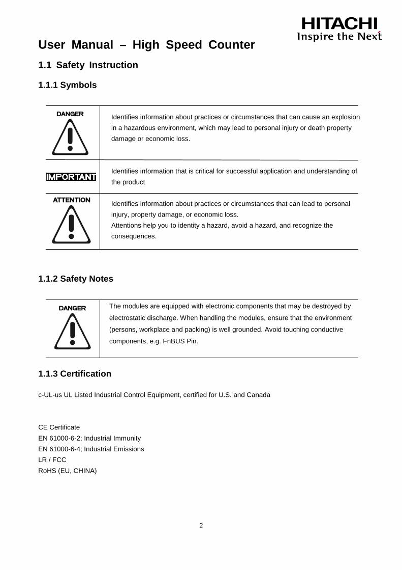
1.1.1 Symbols
Identifies information about practices or circumstances that can cause an explosion in a hazardous environment, which may lead to personal injury or death property damage or economic loss.
Identifies information that is critical for successful application and understanding of the product
Identifies information about practices or circumstances that can lead to personal injury, property damage, or economic loss.
Attentions help you to identity a hazard, avoid a hazard, and recognize the consequences.
1.1.2 Safety Notes
The modules are equipped with electronic components that may be destroyed by
electrostatic discharge. When handling the modules, ensure that the environment
(persons, workplace and packing) is well grounded. Avoid touching conductive
components, e.g. FnBUS Pin.
1.1.3 Certification
c-UL-us UL Listed Industrial Control Equipment, certified for U.S. and Canada CE Certificate EN 61000-6-2; Industrial Immunity EN 61000-6-4; Industrial Emissions LR / FCC RoHS (EU, CHINA)
User Manual – High Speed Counter
3
2. HSC Input Module List
Number Description Remark
RIO2-CU24 1 Channel, High Speed Counter, 24V Input RIO2-CU24L 2 Channel, High Speed Counter, 24V Sink Input
User Manual – High Speed Counter
4
3. Specification
3.1 The Interface
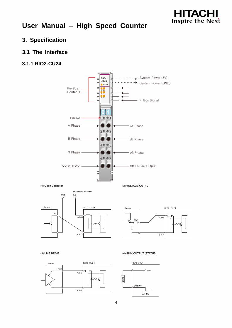
3.1.1 RIO2-CU24
User Manual – High Speed Counter
5
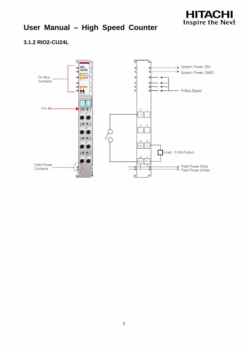
3.1.2 RIO2-CU24L

User Manual – High Speed Counter
6
3.2 General Specification
General Specification
RIO2-CU24 RIO2-CU24L Input Specification
Number of Channel
1 Channel 0-1 Group of A and /A(or GND) 2-3 Group of B and /B(or GND) 4-5 Group of G and /G(or GND)
Max 2 Channel
Indicators
1 Green/Red FnBus Status 2 Green Up/Down Status 3 Green Terminal Input LEDs 1 Green Terminal Output LED
1 Green/Red FnBus Status 2 Green Terminal Input LEDs
Input Voltage(Rated) 24Vdc Input Current 6.1mA@24Vdc Min. On-Status Volt/Current 12Vdc/2.9mA
Max. Off-Status Volt/Current 1.8Vdc/0.15mA 7Vdc/1.0mA
Maximum Input Frequency Max. 1.5MHz Max.100KHz except Encoder x4
Max.50KHz Encoder x4 Input Duty Range 10%~90% 20%~80%
Input Filter Selections
Bypass 1usec 5usec 10usec 50usec 100usec 500usec 1msec 5msec 10msec
None
Counting Mode
1 Pulse Mode 2Pulse Mode Encoder x1 Encoder x2 Encoder x4 Period/Rate Mode PWM Output Mode
1-Input Mode – Up, Down 2-Input Mode – Up/Inhibit, Up/Reset, Down/Inhibit, Down/Reset, Up/Down, Clock/Direction, Encoder x1, Encoder x2, Encoder x4
Gate Function Mode
Store/Continue Store/Wait/Resume Store-Reset/Wait/Start Store-Reset/Start
None
Counter Size 24bit-wide 32bit-wide/Channel Common Type 1 Common 2 Common Output Specification Channel Type 1 Channel Sink Type 2 Channel Source Type Output Voltage 5~28.8Vdc 24Vdc Output Current 0.5A 0.5A/Channel, Short Protection
User Manual – High Speed Counter
7
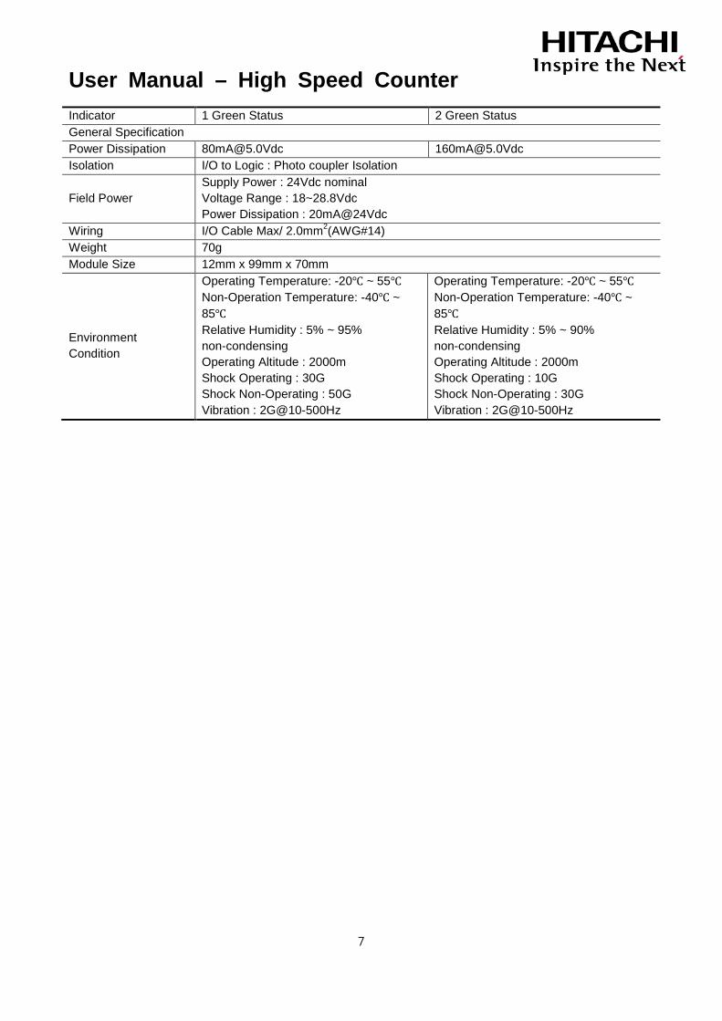
Indicator 1 Green Status 2 Green Status General Specification Power Dissipation [email protected] [email protected] Isolation I/O to Logic : Photo coupler Isolation
Field Power Supply Power : 24Vdc nominal Voltage Range : 18~28.8Vdc Power Dissipation : 20mA@24Vdc
Wiring I/O Cable Max/ 2.0mm2(AWG#14) Weight 70g Module Size 12mm x 99mm x 70mm
Environment Condition
Operating Temperature: -20℃ ~ 55℃ Non-Operation Temperature: -40℃ ~ 85℃ Relative Humidity : 5% ~ 95% non-condensing Operating Altitude : 2000m Shock Operating : 30G Shock Non-Operating : 50G Vibration : 2G@10-500Hz
Operating Temperature: -20℃ ~ 55℃ Non-Operation Temperature: -40℃ ~ 85℃ Relative Humidity : 5% ~ 90% non-condensing Operating Altitude : 2000m Shock Operating : 10G Shock Non-Operating : 30G Vibration : 2G@10-500Hz
User Manual – High Speed Counter
8
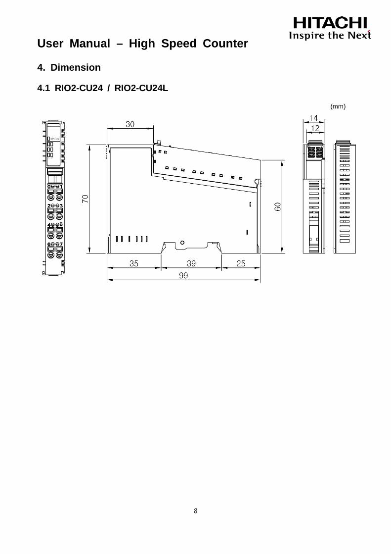
4. Dimension
4.1 RIO2-CU24 / RIO2-CU24L
(mm)

User Manual – High Speed Counter
9
5. Configuration and Operational Function
5.1 RIO2-CU24
5.1.1 I/O Process Image Table
5.1.1.1 Input Image Data – 6byte
Byte Bit 7 Bit 6 Bit 5 Bit 4 Bit 3 Bit 2 Bit 1 Bit 0
0 Current Counter Value(Low) when IDS = 0 Current Counter Value(Low) when IDS = 1
1 Current Counter Value(Middle) when IDS = 0 Current Counter Value(Middle) when IDS = 1
2 Current Counter Value(High) when IDS = 0 Current Counter Value(High) when IDS = 1
3 Always 0
4 Status Low(compared flags) 0 0 SUF SOF SEQL(=) SEQ(=) SLT(<) SGT(>)
5 Status High(same as LED flags) 0 0 SOT SGIN SBIN SAIN SDN SUP
• Current Counter Value
The Current Counter Value is really counting value of incoming pulse. The Current Counter Value can only read to binary number (0 to 16,777,215)
• Status Low (compared flags)
The Status Low can only read. SUF: Status Underflow (Latched) SOF: Status Overflow (Latched) SEQL (=): Status Current count value = Compare count value (Latched) SEQ (=): Status Current count value = Compare count value (Unlatched) SLT (<): Status Current count value < Compare count value (Unlatched) SGT (>): Status Current count value > Compare count value (Unlatched)
• Status High (same as LED display)
The Status High can only read. SUP: Status Counter Up SDN: Status Counter Down SAIN: Status A Terminal Input SBIN: Status B Terminal Input SGIN: Status G Terminal Input SOT: Status Output Terminal (same as OT)

User Manual – High Speed Counter
10
5.1.1.2 Output Image Data – 2byte
Byte Bit 7 Bit 6 Bit 5 Bit 4 Bit 3 Bit 2 Bit 1 Bit 0
0
Status Output Terminal (OT) Control Status Output Terminal Selection “0000” : Force Off “0001” : GT “0010” : LT “0011” : EQ “0101” : Overflow “0110” : Underflow “1001” : Count Up “1010” : Count Down “1011” : A Terminal Input “1100” : B Terminal Input “1101” : G Terminal Input “1110” : PWM Output “1111” : Force On Others : Force Off
Status Output Terminal Pulse Width “0000” : Bypass “0001” : 1msec “0010” : 5msec “0011” : 10msec “0100” : 20msec “0101” : 50msec “0110” : 100msec “0111” : 200msec “1000” : 500msec “1111” : Latched Others : Bypass
1
Command or PWM Duty value (PWM Output Mode)
Command 7 6 5 4 3 2 1 0 HRST CR CP CST PU PO PE IDS
PWM duty value 0~100dec (= 0~100%)
• Status Output Terminal (OT) Control This Status Output Terminal Control can read and write to binary. Below example is output overflow flag in Status Register. When Status flag is the rising, Status Output Terminal Pulse Width is waiting by user setting value until.
User Manual – High Speed Counter
11
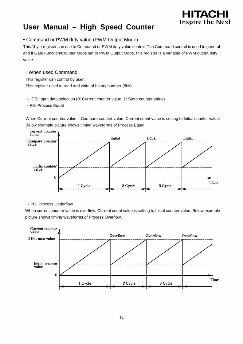
• Command or PWM duty value (PWM Output Mode) This 1byte register can use to Command or PWM duty value control. The Command control is used to general and if Gate Function/Counter Mode set to PWM Output Mode, this register is a variable of PWM output duty value. ◦ When used Command This register can control by user. This register used to read and write of binary number (8bit).
- IDS: Input data selection (0: Current counter value, 1: Store counter value) - PE: Process Equal
When Current counter value = Compare counter value, Current count value is setting to Initial counter value. Below example picture shows timing waveforms of Process Equal.
- PO: Process Underflow When current counter value is overflow. Current count value is setting to Initial counter value. Below example picture shows timing waveforms of Process Overflow.
User Manual – High Speed Counter
12
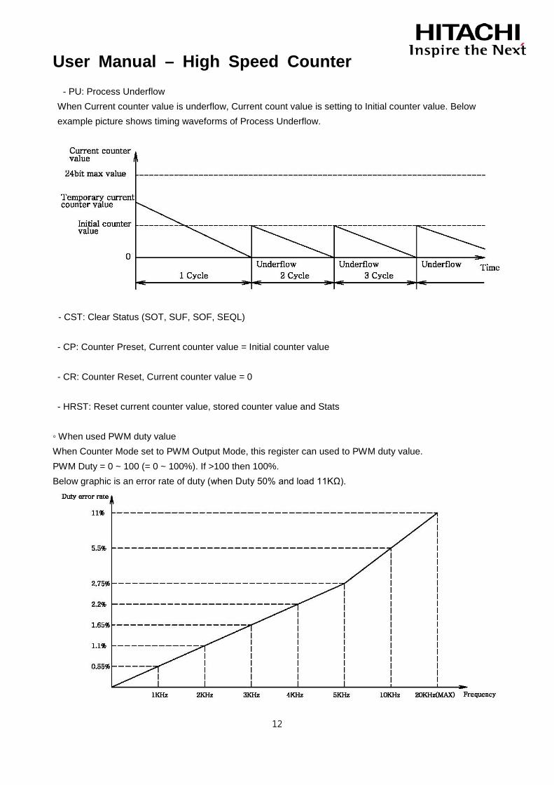
- PU: Process Underflow When Current counter value is underflow, Current count value is setting to Initial counter value. Below example picture shows timing waveforms of Process Underflow.
- CST: Clear Status (SOT, SUF, SOF, SEQL)
- CP: Counter Preset, Current counter value = Initial counter value - CR: Counter Reset, Current counter value = 0 - HRST: Reset current counter value, stored counter value and Stats
◦ When used PWM duty value When Counter Mode set to PWM Output Mode, this register can used to PWM duty value. PWM Duty = 0 ~ 100 (= 0 ~ 100%). If >100 then 100%. Below graphic is an error rate of duty (when Duty 50% and load 11KΩ).
User Manual – High Speed Counter
13
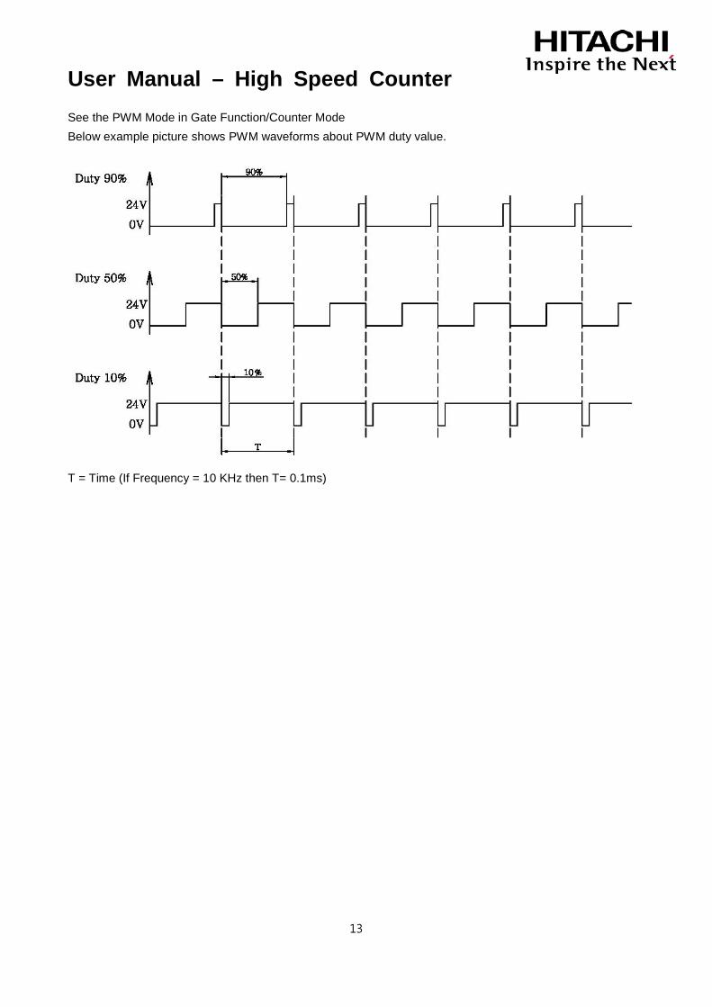
See the PWM Mode in Gate Function/Counter Mode Below example picture shows PWM waveforms about PWM duty value.
T = Time (If Frequency = 10 KHz then T= 0.1ms)

User Manual – High Speed Counter
14
5.1.1.3 Configuration Parameter Table – 2byte
Byte Bit 7 Bit 6 Bit 5 Bit 4 Bit 3 Bit 2 Bit 1 Bit 0
0
Counter Mode / Gate Function Gate Function “0000” : Gate Function Disabled “0001” : Store/Continue “0010” : Store/Wait/Resume “0011” : Store-Reset/Wait/Start “0100” : Store-Reset/Start Others : Gate Function Disabled
Count Mode “0000” : Counter Disabled “0001” : 1Pulse Mode “0010” : 2Pulse Mode “0011” : Encoder x1 “0100” : Encoder x2 “0101” : Encoder x4 “0110” : Period/Rate Mode “0111” : reserved “1000” : PWM Output Mode “1001” : reserved Others : Counter Disable
1
Input Filter / Gate Sampling Time Gate Sampling Time “0000” : (10/1)MHz (0.1usec) “0001” : (10/2)MHz (0.2usec) “0010” : (10/4)MHz (0.4usec) “0011” : (10/8)MHz (0.8usec) “0100” : (10/16)MHz (1.6usec) “0101” : (10/32)MHz (3.2usec) “0110” : (10/64)MHz (6.4usec) “0111” : (10/128)MHz (12.8usec) Others : (10/1)MHz (0.1usec)
Input Filter “0000” : Bypass(about 1.5MHz) “0001”: 1usec (500KHz±30%) “0010”: 5usec (100KHz±30%) “0011”: 10usec (50KHz±30%) “0100”: 50usec (10KHz±30%) “0101”: 100usec (5KHz±30%) “0110”: 500usec (1KHz±30%) “0111”: 1msec (500Hz±30%) “1000”: 5msec (100Hz±30%) “1001”: 10msec (50Hz±30%) Others : Bypass(about 1.5MHz)
Configuration Parameter can only be used to explicit message. Refer Explicit Message table in Network Adapter manual. • Gate Function/Counter Mode (Parameter Byte #0) ◦ Counter Mode - 1 Pulse Mode (A: Pulse, B: Direction) The 1 Pulse Mode reads incoming pulses and returns a binary number (0 to 16,777,215) to FnBus. The 1 Pulse Modes accepts only one-phase inputs. The module determines the Phase B input status to up or down count. (B Phase = High: Down Counter, B Phase = Low: Up Counter) Below example picture shows timing waveforms of 1 Pulse Method Pulse Mode.
User Manual – High Speed Counter
15
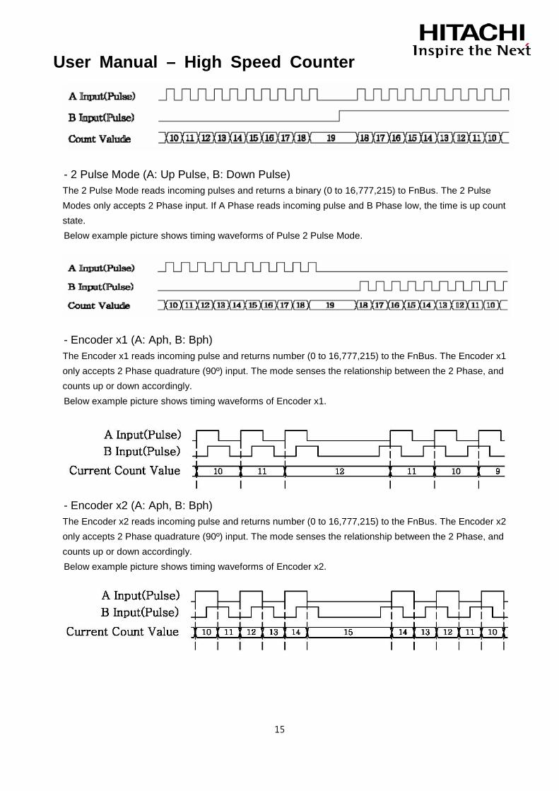
- 2 Pulse Mode (A: Up Pulse, B: Down Pulse) The 2 Pulse Mode reads incoming pulses and returns a binary (0 to 16,777,215) to FnBus. The 2 Pulse Modes only accepts 2 Phase input. If A Phase reads incoming pulse and B Phase low, the time is up count state. Below example picture shows timing waveforms of Pulse 2 Pulse Mode.
- Encoder x1 (A: Aph, B: Bph) The Encoder x1 reads incoming pulse and returns number (0 to 16,777,215) to the FnBus. The Encoder x1 only accepts 2 Phase quadrature (90º) input. The mode senses the relationship between the 2 Phase, and counts up or down accordingly. Below example picture shows timing waveforms of Encoder x1.
- Encoder x2 (A: Aph, B: Bph) The Encoder x2 reads incoming pulse and returns number (0 to 16,777,215) to the FnBus. The Encoder x2 only accepts 2 Phase quadrature (90º) input. The mode senses the relationship between the 2 Phase, and counts up or down accordingly. Below example picture shows timing waveforms of Encoder x2.
User Manual – High Speed Counter
16
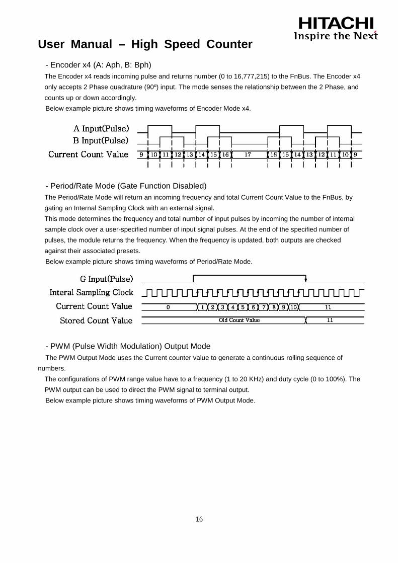
- Encoder x4 (A: Aph, B: Bph) The Encoder x4 reads incoming pulse and returns number (0 to 16,777,215) to the FnBus. The Encoder x4 only accepts 2 Phase quadrature (90º) input. The mode senses the relationship between the 2 Phase, and counts up or down accordingly. Below example picture shows timing waveforms of Encoder Mode x4.
- Period/Rate Mode (Gate Function Disabled) The Period/Rate Mode will return an incoming frequency and total Current Count Value to the FnBus, by gating an Internal Sampling Clock with an external signal. This mode determines the frequency and total number of input pulses by incoming the number of internal sample clock over a user-specified number of input signal pulses. At the end of the specified number of pulses, the module returns the frequency. When the frequency is updated, both outputs are checked against their associated presets. Below example picture shows timing waveforms of Period/Rate Mode.
- PWM (Pulse Width Modulation) Output Mode The PWM Output Mode uses the Current counter value to generate a continuous rolling sequence of
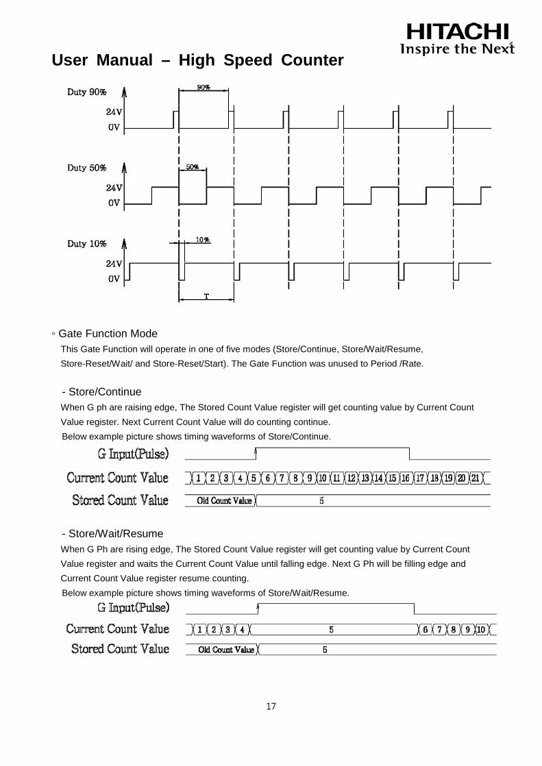
numbers. The configurations of PWM range value have to a frequency (1 to 20 KHz) and duty cycle (0 to 100%). The PWM output can be used to direct the PWM signal to terminal output. Below example picture shows timing waveforms of PWM Output Mode.
User Manual – High Speed Counter
17
◦ Gate Function Mode This Gate Function will operate in one of five modes (Store/Continue, Store/Wait/Resume, Store-Reset/Wait/ and Store-Reset/Start). The Gate Function was unused to Period /Rate. - Store/Continue When G ph are raising edge, The Stored Count Value register will get counting value by Current Count Value register. Next Current Count Value will do counting continue. Below example picture shows timing waveforms of Store/Continue.
- Store/Wait/Resume When G Ph are rising edge, The Stored Count Value register will get counting value by Current Count Value register and waits the Current Count Value until falling edge. Next G Ph will be filling edge and Current Count Value register resume counting. Below example picture shows timing waveforms of Store/Wait/Resume.
User Manual – High Speed Counter
18
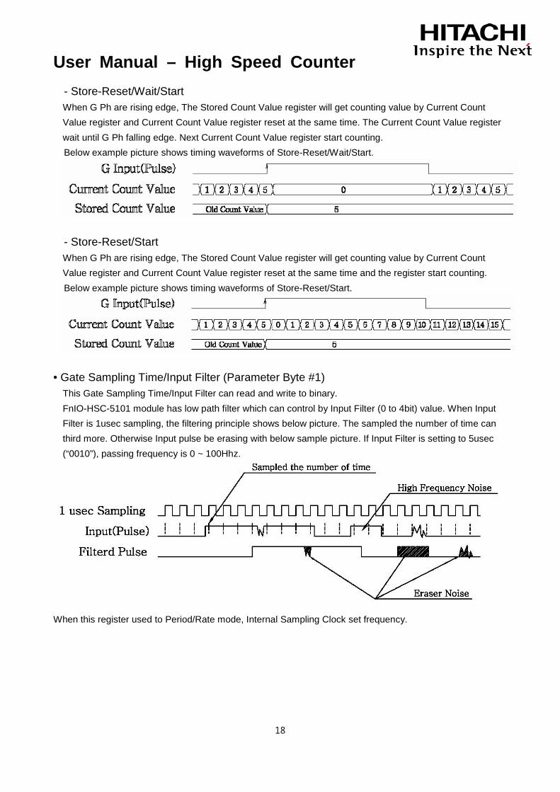
- Store-Reset/Wait/Start When G Ph are rising edge, The Stored Count Value register will get counting value by Current Count Value register and Current Count Value register reset at the same time. The Current Count Value register wait until G Ph falling edge. Next Current Count Value register start counting. Below example picture shows timing waveforms of Store-Reset/Wait/Start.
- Store-Reset/Start When G Ph are rising edge, The Stored Count Value register will get counting value by Current Count Value register and Current Count Value register reset at the same time and the register start counting. Below example picture shows timing waveforms of Store-Reset/Start.
• Gate Sampling Time/Input Filter (Parameter Byte #1) This Gate Sampling Time/Input Filter can read and write to binary. FnIO-HSC-5101 module has low path filter which can control by Input Filter (0 to 4bit) value. When Input Filter is 1usec sampling, the filtering principle shows below picture. The sampled the number of time can third more. Otherwise Input pulse be erasing with below sample picture. If Input Filter is setting to 5usec (“0010”), passing frequency is 0 ~ 100Hhz.
When this register used to Period/Rate mode, Internal Sampling Clock set frequency.

User Manual – High Speed Counter
19
5.1.1.4 Memory Register Map
Byte Offset Access Description Default
Value 0 R Current count value(Low byte) (Input Data Byte#0) 0x00 1 R Current count value(Middle byte) (Input Data Byte#1) 0x00
2 R Current count value(High byte) (Input Data Byte#2) 0x00
3 R Always 0 (Input Data Byte#3) 0x00
4 R Status Low(compared flags) (Input Data Byte#4) 0x00
5 R Status High(same as LED display) (Input Data Byte#5) 0x00
6 R Output Terminal(OT) Control (Output Data Byte#0) 0x00
7 R SSR(Special Selection Register) (Output Data Byte#1) 0x00
8 R/W Gate Function/Counter Mode (Parameter Byte#0) 0x00
9 R/W Gate Sampling Time/Input Filter (Parameter Byte#1) 0x00
10 R/W Don’t care 0x00
11 R/W Don’t care 0x00
12 R Stored count value(Low Byte) (Input Data Byte#0) 0x00
13 R Stored count value(Middle Byte) (Input Data Byte#1) 0x00
14 R Stored count value(High Byte) (Input Data Byte#2) 0x00
15 R Always 0 (Input Data Byte#3) 0x00
16 R/W Initial Counter Value(Low Byte) (Initial counter or PWM Frequency value)
0x00
17 R/W Initial Counter Value(Middle Byte) (Initial counter or PWM Frequency value)
0x00
18 R/W Initial Counter Value(High Byte) (Initial counter or PWM Frequency value)
0x00
19 R/W Always 0 0x00
20 R/W Compare count value(Low Byte) 0x00
21 R/W Compare count value(Middle Byte) 0x00
22 R/W Compare count value(High Byte) 0x00
23 R/W Always 0 0x00
Some Memory Registers can only be used to explicit message. Refer Explicit Message table in Network Adapter manual.

User Manual – High Speed Counter
20
• Stored counter value Register This register can only return to 24bit binary number (0 to 16,777,215). This register used to Period/Rate and Gate Counter mode.
• Initial Counter Value
This 4byte register can do use to Initial counter or PWM Frequency value control. The Initial counter value is used to general configuration the Current counter value and if Gate Function/Counter Mode set to PWM Output Mode, this register is a variable of PWM output frequency value.
◦ General configuration for initial current counter
RIO2-CU24 Module exist Initial counter value for starting of Current count value. Current count value begins starting from Initial counter value. User can configuration of Initial counter value. If user can’t configuration of Initial counter value, that is fixed to value (0x000000). This Initial counter value used to PO, PU and PE. This Initial counter value can reading and writing to binary number (0 to 16,777,215).
◦ Setting PWM Frequency value
If Gate Function/Counter Mode set to PWM Output Mode, this register is frequency value of PWM output PWM Frequency = 1 ~ 20000 (=1Hz~20 KHz). If PWM Frequency value < 1 then off, if PWM Frequency value > 20000 then 20 KHz Below example picture shows timing waveforms of PWM Output Mode.

User Manual – High Speed Counter
21
• Compare counter value Model RIO2-CU24 is equipped with Module Compare counter value to compare with Current Count Value Status does transformation by compare value of Current Count Value and Compare Value Set Register. Compare counter value used to comparison Current Counter value for Status. If user can’t configuration of Compare counter value, that is fixed to value (0x000000). This register use to PO, PU, PE and Status output. This register can reading and writing to binary number (0 to 16,777,215).
User Manual – High Speed Counter
22
5.2 RIO2-CU24L
5.2.1 I/O Process Image Table
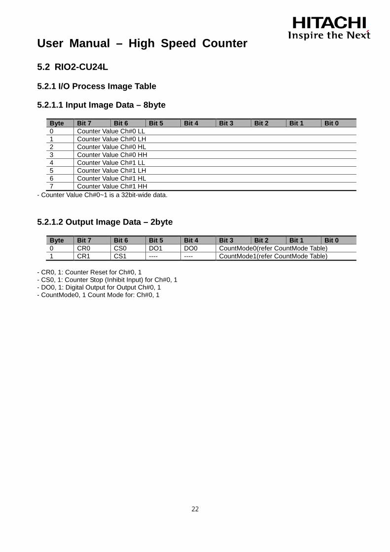
5.2.1.1 Input Image Data – 8byte
Byte Bit 7 Bit 6 Bit 5 Bit 4 Bit 3 Bit 2 Bit 1 Bit 0 0 Counter Value Ch#0 LL 1 Counter Value Ch#0 LH 2 Counter Value Ch#0 HL 3 Counter Value Ch#0 HH 4 Counter Value Ch#1 LL 5 Counter Value Ch#1 LH 6 Counter Value Ch#1 HL 7 Counter Value Ch#1 HH
- Counter Value Ch#0~1 is a 32bit-wide data.
5.2.1.2 Output Image Data – 2byte
Byte Bit 7 Bit 6 Bit 5 Bit 4 Bit 3 Bit 2 Bit 1 Bit 0 0 CR0 CS0 DO1 DO0 CountMode0(refer CountMode Table) 1 CR1 CS1 ---- ---- CountMode1(refer CountMode Table)
- CR0, 1: Counter Reset for Ch#0, 1 - CS0, 1: Counter Stop (Inhibit Input) for Ch#0, 1 - DO0, 1: Digital Output for Output Ch#0, 1 - CountMode0, 1 Count Mode for: Ch#0, 1
User Manual – High Speed Counter
23
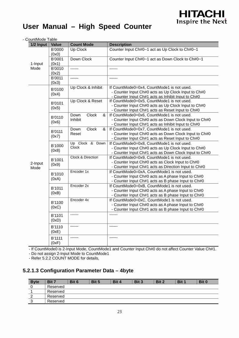
- CountMode Table 1/2 Input Value Count Mode Description
1-Input Mode
B’0000 (0x0)
Up Clock Counter Input Ch#0~1 act as Up Clock to Ch#0~1
B’0001 (0x1)
Down Clock Counter Input Ch#0~1 act as Down Clock to Ch#0~1
B’0010 (0x2)
------ ------
B’0011 (0x3)
------ ------
2-Input Mode
B’0100 (0x4)
Up Clock & Inhibit If CountMode0=0x4, CountMode1 is not used. - Counter Input Ch#0 acts as Up Clock Input to Ch#0 - Counter Input Ch#1 acts as Inhibit Input to Ch#0
B’0101 (0x5)
Up Clock & Reset If CountMode0=0x5, CountMode1 is not used. - Counter Input Ch#0 acts as Up Clock Input to Ch#0 - Counter Input Ch#1 acts as Reset Input to Ch#0
B’0110 (0x6)
Down Clock & Inhibit
If CountMode0=0x6, CountMode1 is not used. - Counter Input Ch#0 acts as Down Clock Input to Ch#0 - Counter Input Ch#1 acts as Inhibit Input to Ch#0
B’0111 (0x7)
Down Clock & Reset
If CountMode0=0x7, CountMode1 is not used. - Counter Input Ch#0 acts as Down Clock Input to Ch#0 - Counter Input Ch#1 acts as Reset Input to Ch#0
B’1000 (0x8)
Up Clock & Down Clock
If CountMode0=0x8, CountMode1 is not used. - Counter Input Ch#0 acts as Up Clock Input to Ch#0 - Counter Input Ch#1 acts as Down Clock Input to Ch#0
B’1001 (0x9)
Clock & Direction If CountMode0=0x9, CountMode1 is not used. - Counter Input Ch#0 acts as Clock Input to Ch#0 - Counter Input Ch#1 acts as Direction Input to Ch#0
B’1010 (0xA)
Encoder 1x If CountMode0=0xA, CountMode1 is not used. - Counter Input Ch#0 acts as A phase Input to Ch#0 - Counter Input Ch#1 acts as B phase Input to Ch#0
B’1011 (0xB)
Encoder 2x If CountMode0=0xB, CountMode1 is not used. - Counter Input Ch#0 acts as A phase Input to Ch#0 - Counter Input Ch#1 acts as B phase Input to Ch#0
B’1100 (0xC)
Encoder 4x If CountMode0=0xC, CountMode1 is not used. - Counter Input Ch#0 acts as A phase Input to Ch#0 - Counter Input Ch#1 acts as B phase Input to Ch#0
B’1101 (0xD)
------ ------
B’1110 (0xE)
------ ------
B’1111 (0xF)
------ ------
- If CountMode0 is 2-Input Mode, CountMode1 and Counter Input Ch#0 do not affect Counter Value Ch#1. - Do not assign 2-Input Mode to CountMode1 - Refer 5.2.2 COUNT MODE for details,
5.2.1.3 Configuration Parameter Data – 4byte
Byte Bit 7 Bit 6 Bit 5 Bit 4 Bit 3 Bit 2 Bit 1 Bit 0 0 Reserved 1 Reserved 2 Reserved 3 Reserved

User Manual – High Speed Counter
24
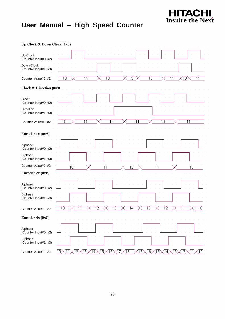
5.2.2 COUNT MODE
Up Clock (0x0) Down Clock (0x1)
Up Clock & Inhibit (0x4)
Up Clock & Reset (0x5)
Down Clock & Inhibit (0x6)
Down Clock & Reset (0x7)
Up Clock (Counter Input#0~3)
Counter Value#0~3
Down Clock (Counter Input#0~3)
Counter Value#0~3
Up Clock (Counter Input#0, #2)
Counter Value#0, #2
Inhibit (Counter Input#1, #3)
Up Clock (Counter Input#0, #2)
Counter Value#0, #2
Reset (Counter Input#1, #3)
Down Clock (Counter Input#0, #2)
Counter Value#0, #2
Inhibit (Counter Input#1, #3)
Down Clock (Counter Input#0, #2)
Counter Value#0, #2
Reset (Counter Input#1, #3)
User Manual – High Speed Counter
25
Up Clock & Down Clock (0x8)
Clock & Direction (0x9)
Encoder 1x (0xA)
Encoder 2x (0xB)
Encoder 4x (0xC)
Up Clock (Counter Input#0, #2)
Counter Value#0, #2
Down Clock (Counter Input#1, #3)
Clock (Counter Input#0, #2)
Counter Value#0, #2
Direction (Counter Input#1, #3)
A phase (Counter Input#0, #2)
Counter Value#0, #2
B phase (Counter Input#1, #3)
A phase (Counter Input#0, #2)
Counter Value#0, #2
B phase (Counter Input#1, #3)
A phase (Counter Input#0, #2)
Counter Value#0, #2
B phase (Counter Input#1, #3)
User Manual – High Speed Counter
26
6. Trouble Shooting
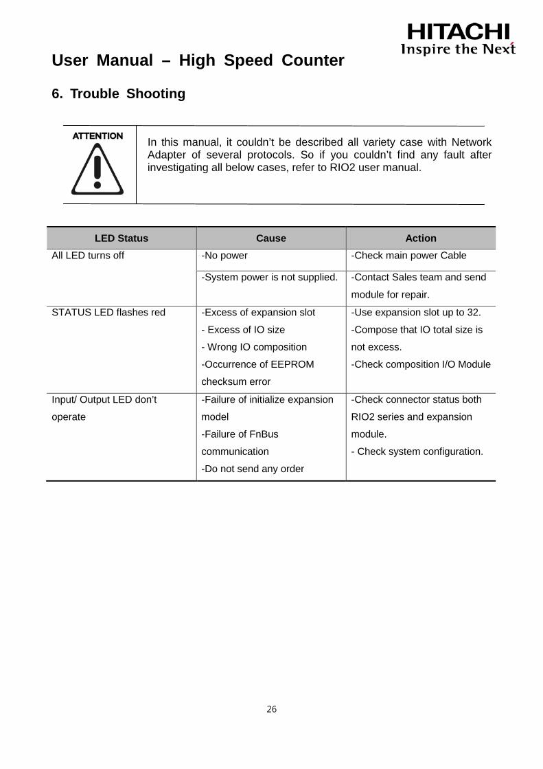
In this manual, it couldn’t be described all variety case with Network Adapter of several protocols. So if you couldn’t find any fault after investigating all below cases, refer to RIO2 user manual.
LED Status Cause Action All LED turns off
-No power -Check main power Cable
-System power is not supplied. -Contact Sales team and send
module for repair.
STATUS LED flashes red -Excess of expansion slot
- Excess of IO size
- Wrong IO composition
-Occurrence of EEPROM
checksum error
-Use expansion slot up to 32.
-Compose that IO total size is
not excess.
-Check composition I/O Module
Input/ Output LED don’t
operate
-Failure of initialize expansion
model
-Failure of FnBus
communication
-Do not send any order
-Check connector status both
RIO2 series and expansion
module.
- Check system configuration.

Hitachi Europe GmbH Am Seestern 18 Tel: +49 (0) 211 52 83-0 D-40547 Düsseldorf, Germany Fax: +49 (0) 211 52 83-649